

DS19330
Model:
COLOR TELEVISION
AS
FILE NO.
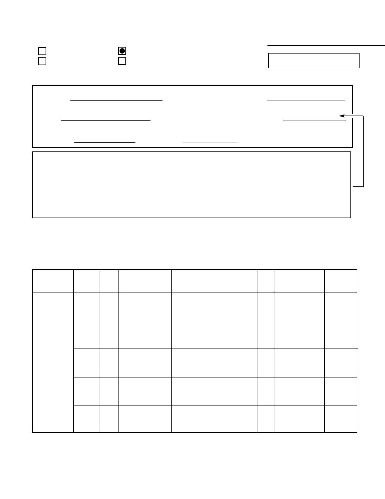
DS19330, G8MCM, PRODUCT CODE 111363880
REFERENCE No. SS780042-04
Notice
CORRECTION
SERVICE FLASH
PRODUCTION CHANGE
ADD INFORMATION
Please add this notice to the Service Manual listed below.
REVISION 4
Category :
U.S.A.
Destination:
June / 15 / 2003
Date:
19330-04
Effective from : Chassis No.
SS780042-02
REF : No.
NOTE: Match the Chassis No. on the unit’s back cover with the Chassis No. in the Service
Manual. If the Service Manual Chassis No. does not match the unit’s, additional Service
Literature is required. This chassis is similar to Chassis No. 19330-02. Only the
difference Service Information is given in this manual. For detailed Service Information,
refer to the Original Service Manual and Notices for Chassis No. 19330-02 used in Model
DS19330 (SS780042-02).
1. IN THE CHASSIS ELECTRICAL PARTS LIST
The reason for change.
A : Misprint B : Quality Reliability C : Standardization
D : Design E : Add as a possible sub F : Schematic location change
G : Purchasing Request
Page &
Section
Schematic
Location
Part No.
Description
Q’ty
Interchange-
ability
Reason
403 346 7126 MT-POLYPRO 0.27U M 250V
Old 403 372 6807 MT-POLYPRO 0.27U J 250V 1 NO
404 081 2609 MT-POLYPRO 0.27U J 200V
★
C417 - - - - - - - - - - - - - - - - - - - - - - - - - - - - - - - - - - - - - - - - - - - - - - - - - - - - - - - - - - - - - - D
403 349 3204 MT-POLYPRO 0.3U M 250V
New 403 372 6906 MT-POLYPRO 0.3U J 250V 1 NO
404 081 2708 MT-POLYPRO 0.3U J 200V
Old 401 286 5305 MT-FILM 2.4K FA 1/6W 1 NO
★
R421 - - - - - - - - - - - - - - - - - - - - - - - - - - - - - - - - - - - - - - - - - - - - - - - - - - - - - - - - - - - - - - D
New 401 148 7201 MT-FILM 1.8K FA 1/6W 1 NO
Old 401 066 3002 OXIDE-MT 2.2 JA 2W 1 NO
★
R497 - - - - - - - - - - - - - - - - - - - - - - - - - - - - - - - - - - - - - - - - - - - - - - - - - - - - - - - - - - - - - - D
New 401 057 9907 OXIDE-MT 1.5 JA 1W 1 NO
Old NOT USED 0 NO
R498 - - - - - - - - - - - - - - - - - - - - - - - - - - - - - - - - - - - - - - - - - - - - - - - - - - - - - - - - - - - - - - D
New 401 014 1609 CARBON 15 JA 1/4W 1 NO
Page 14,
Chassis
Electrical
Parts List
Page 16,
Chassis
Electrical
Parts List
Parts list continued on back.
For parts or service contact
21605 Plummer Street
Chatsworth, CA 91311 (U.S.A.)
300 Applewood Crescent,
Concord, Ontario L4K 5C7 (CANADA)
SANYO Fisher Service Corporation
June / 2003 / 2000 SMC
Printed in U.S.A.
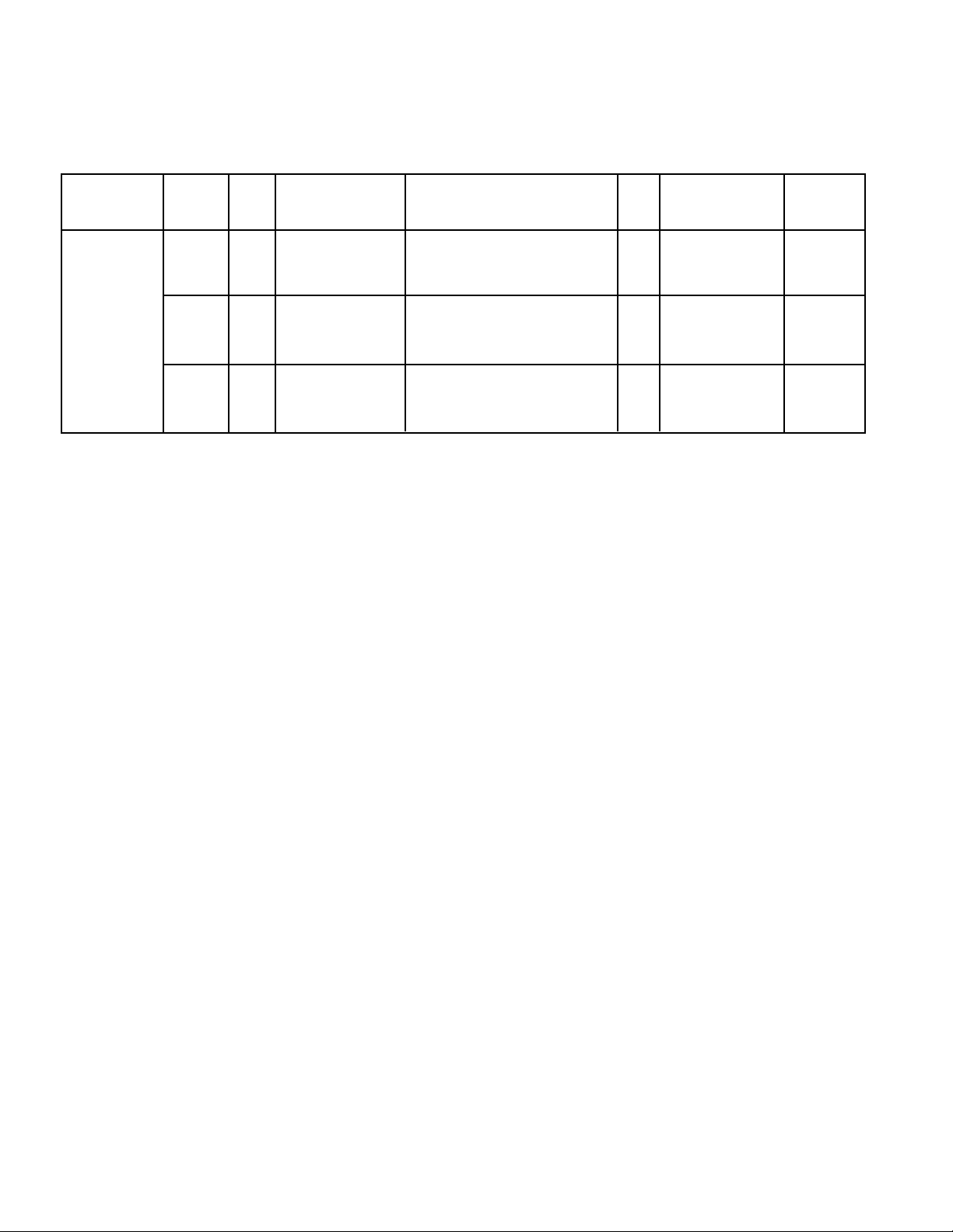
1. IN THE CHASSIS ELECTRICAL PARTS LIST (Continued)
The reason for change.
A : Misprint B : Quality Reliability C : Standardization
D : Design E : Add as a possible sub F : Schematic location change
G : Purchasing Request
Page &
Section
Schematic
Location
Part No.
Description
Q’ty
Interchange-
ability
Reason
Old 645 057 4832 TRANS, FLYBACK 1 NO
★
T402 - - - - - - - - - - - - - - - - - - - - - - - - - - - - - - - - - - - - - - - - - - - - - - - - - - - - - - - - - - - - - - D
New 652 001 0383 TRANS, FLYBACK 1 NO
Old 610 302 5476 ASSY, PWB, MAIN 1 NO
A100 - - - - - - - - - - - - - - - - - - - - - - - - - - - - - - - - - - - - - - - - - - - - - - - - - - - - - - - - - - - - - - D
New 610 305 7842 ASSY, PWB, MAIN 1 NO
Old 610 302 5483 ASSY, PWB, SOCKET 1 YES
A700 - - - - - - - - - - - - - - - - - - - - - - - - - - - - - - - - - - - - - - - - - - - - - - - - - - - - - - - - - - - - - - D
New 610 305 7859 ASSY, PWB, SOCKET 1 YES
Page 18,
Chassis
Electrical
Parts List
DS19330
Model:
COLOR TELEVISION
AS
FILE NO.
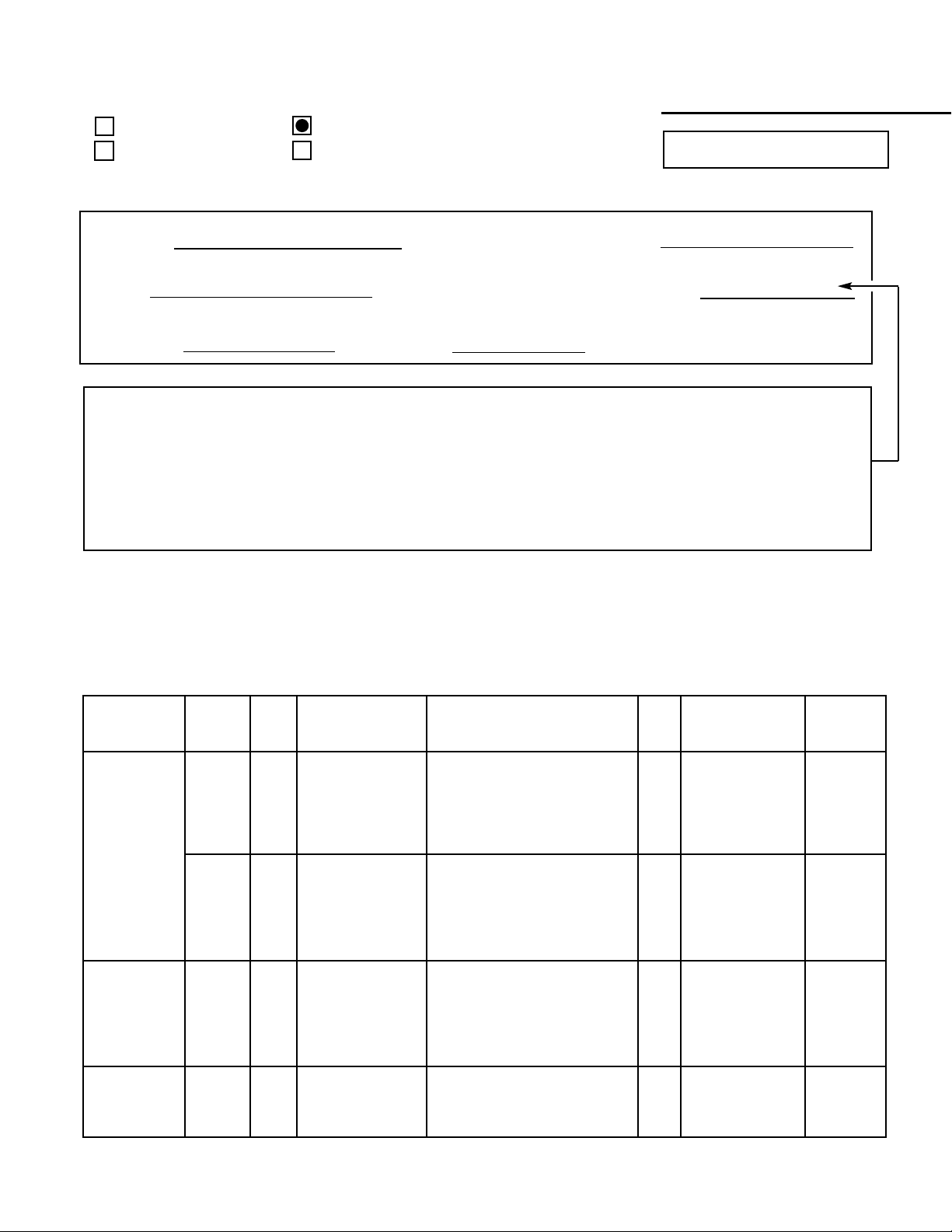
DS19330, G8MBM, PRODUCT CODE 111363880
REFERENCE No. SS780042-03
Notice
CORRECTION
SERVICE FLASH
PRODUCTION CHANGE
ADD INFORMATION
Please add this notice to the Service Manual listed below.
REVISION 3
Category :
U.S.A.
Destination:
June / 15 / 2003
Date:
19330-03
Effective from : Chassis No.
SS780042-02
REF : No.
NOTE: Match the Chassis No. on the unit’s back cover with the Chassis No. in the Service
Manual. If the Service Manual Chassis No. does not match the unit’s, additional Service
Literature is required. This chassis is similar to Chassis No. 19330-02. Only the
difference Service Information is given in this manual. For detailed Service Information,
refer to the Original Service Manual and Notices for Chassis No. 19330-02 used in Model
DS19330 (SS780042-02).
1. IN THE CHASSIS ELECTRICAL PARTS LIST
The reason for change.
A : Misprint B : Quality Reliability C : Standardization
D : Design E : Add as a possible sub F : Schematic location change
G : Purchasing Request
Page &
Section
Schematic
Location
Part No.
Description
Q’ty
Interchange-
ability
Reason
Old
404 077 4709 MT-POLYPRO 8000P H 1.5K
1NO
403 343 8304 MT-POLYPRO 8000P H 1.5K
★
C411 - - - - - - - - - - - - - - - - - - - - - - - - - - - - - - - - - - - - - - - - - - - - - - - - - - - - - - - - - - - - - - D
New
404 077 3108 MT-POLYPRO 7500P H 1.5K
1NO
403 343 8007 MT-POLYPRO 7200P H 1.5K
Old NOT USED 0 NO
★
C416 - - - - - - - - - - - - - - - - - - - - - - - - - - - - - - - - - - - - - - - - - - - - - - - - - - - - - - - - - - - - - - D
404 088 2503 MT-POLYPRO 0.47U M 200V
New 403 364 9304 MT-POLYPRO 0.47U J 250V 1 NO
403 382 7108 MT-POLYPRO 0.47U J 250V
403 346 7126 MT-POLYPRO 0.27U M 250V
Old 403 372 6807 MT-POLYPRO 0.27U J 250V 1 NO
404 081 2609 MT-POLYPRO 0.27U J 200V
★
C417 - - - - - - - - - - - - - - - - - - - - - - - - - - - - - - - - - - - - - - - - - - - - - - - - - - - - - - - - - - - - - - D
New N/A NOT USED 0 NO
Old 645 026 3927 DEFLECTION YOKE 1 NO
★
L902 - - - - - - - - - - - - - - - - - - - - - - - - - - - - - - - - - - - - - - - - - - - - - - - - - - - - - - - - - - - - - - D
New 645 042 7718 DEFLECTION YOKE 1 NO
Page 13,
Chassis
Electrical
Parts List
Page 14,
Chassis
Electrical
Parts List
Page 15,
Chassis
Electrical
Parts List

For parts or service contact
21605 Plummer Street
Chatsworth, CA 91311 (U.S.A.)
300 Applewood Crescent,
Concord, Ontario L4K 5C7 (CANADA)
SANYO Fisher Service Corporation
June / 2003 / 2000 SMC
Printed in U.S.A.
1. IN THE CHASSIS ELECTRICAL PARTS LIST (Continued)
The reason for change.
A : Misprint B : Quality Reliability C : Standardization
D : Design E : Add as a possible sub F : Schematic location change
G : Purchasing Request
Page &
Section
Schematic
Location
Part No.
Description
Q’ty
Interchangeability
Reason
Old 401 066 3002 OXIDE-MT 2.2 JA 2W 1 NO
★
R497 - - - - - - - - - - - - - - - - - - - - - - - - - - - - - - - - - - - - - - - - - - - - - - - - - - - - - - - - - - - - - - D
New 401 068 1600 OXIDE-MT 4.7 JA 2W 1 NO
Old 401 255 9006 MT-GLAZE 82 JA 1/10W 1 NO
R714 - - - - - - - - - - - - - - - - - - - - - - - - - - - - - - - - - - - - - - - - - - - - - - - - - - - - - - - - - - - - - - D
New N/A NOT USED 0 N0
Old N/A NOT USED 0 N0
R718 - - - - - - - - - - - - - - - - - - - - - - - - - - - - - - - - - - - - - - - - - - - - - - - - - - - - - - - - - - - - - - D
New 401 255 9006 MT-GLAZE 82 JA 1/10W 1 NO
Old 401 255 9006 MT-GLAZE 82 JA 1/10W 1 NO
R724 - - - - - - - - - - - - - - - - - - - - - - - - - - - - - - - - - - - - - - - - - - - - - - - - - - - - - - - - - - - - - - D
New N/A NOT USED 0 N0
Old N/A NOT USED 0 N0
R728 - - - - - - - - - - - - - - - - - - - - - - - - - - - - - - - - - - - - - - - - - - - - - - - - - - - - - - - - - - - - - - D
New 401 255 9006 MT-GLAZE 82 JA 1/10W 1 NO
Old 610 302 5476 ASSY, PWB, MAIN 1 NO
A100 - - - - - - - - - - - - - - - - - - - - - - - - - - - - - - - - - - - - - - - - - - - - - - - - - - - - - - - - - - - - - - D
New 610 305 7811 ASSY, PWB, MAIN 1 NO
Old 610 302 5483 ASSY, PWB, SOCKET 1 N0
A700 - - - - - - - - - - - - - - - - - - - - - - - - - - - - - - - - - - - - - - - - - - - - - - - - - - - - - - - - - - - - - - D
New 610 305 7828 ASSY, PWB, SOCKET 1 NO
Old 645 028 0306 SOCKET, CRT 8P 1 NO
★
K701 - - - - - - - - - - - - - - - - - - - - - - - - - - - - - - - - - - - - - - - - - - - - - - - - - - - - - - - - - - - - - - D
New N/A NOT USED 0 NO
Old N/A NOT USED 0 NO
★
K701A - - - - - - - - - - - - - - - - - - - - - - - - - - - - - - - - - - - - - - - - - - - - - - - - - - - - - - - - - - - - - - D
New 652 001 1106 SOCKET, CRT 8P 1 NO
Old 414 009 3205 CRT A48KRD82X(DT) 1 NO
★
Q901 - - - - - - - - - - - - - - - - - - - - - - - - - - - - - - - - - - - - - - - - - - - - - - - - - - - - - - - - - - - - - - D
New 414 009 8101 CRT A48JLL40X 1 NO
Old 610 217 7794 CG PURITY MAGNET 1 NO
Q901C - - - - - - - - - - - - - - - - - - - - - - - - - - - - - - - - - - - - - - - - - - - - - - - - - - - - - - - - - - - - - - D
New 610 217 7787 CG PURITY MAGNET 1 NO
Page 16,
Chassis
Electrical
Parts List
Page 18,
Chassis
Electrical
Parts List
Page 17,
Chassis
Electrical
Parts List
Specifications
Power Rating . . . . . . . . . . . . . . . . . . . . . 120V, 60Hz
58W (Avg), 1.4A (Max)
Antenna Input Impedance. . . . . . . . . . . . . . . . . 75Ω
UHF/VHF/CATV
Receiving Channel . . . . . . . . . . . . . . . . 2 - 13 (VHF),
14 - 69 (UHF),
01, 14-94, 95-125 (CATV)
Remote Ready . . . . . . . . . . 24 Key Remote Control
Sound Output . . . . . . . . . . . . . . . . . . . . . . 1.0 W/CH
Intermediate Frequency
Picture IF Carrier. . . . . . . . . . . . . . . . . . 45.75MHz
Sound IF Carrier . . . . . . . . . . . . . . . . . . 41.25MHz
Color Sub Carrier . . . . . . . . . . . . . . . . . 42.17MHz
Picture Tube. . . . . . . . . . . . . . . . . . A48KRD82X(DT)
Semiconductors
Integrated Circuits. . . . . . . . . . . . . . . . . . . . . . . . 7
Transistors. . . . . . . . . . . . . . . . . . . . . . . . . . . . . 14
Except within Tuner and RC Pre-Amp.
Cabinet Dimensions
Width. . . . . . . . . . . . . . . . . . . . . . . . . . . . . 488mm
Height . . . . . . . . . . . . . . . . . . . . . . . . . . . . 438mm
Depth. . . . . . . . . . . . . . . . . . . . . . . . . . . . . 470mm
REFERENCE No. SS780042-02
DS19330, G8MAM, PRODUCT CODE 111363880
Contents
Safety Instructions . . . . . . . . . . . . . . . . . . 2
Service Adjustments. . . . . . . . . . . . . . 3 - 8
Service Hints. . . . . . . . . . . . . . . . . . . . . . . 9
Purity and Convergence . . . . . . . . . 10 - 11
Mechanical Disassemblies. . . . . . . . . . . 12
Chassis Electrical Parts List . . . . . . 13 - 18
Cabinet Parts List . . . . . . . . . . . . . . . . . . 19
Component and Test Point
Locations . . . . . . . . . . . . . . . . . . . 20 - 23
Schematic Insert . . . . . . . . . . . . . . . 25 - 32
Schematic Notes . . . . . . . . . . . . . . . . . 25
Pin Layouts . . . . . . . . . . . . . . . . . . . . . 25
Capacitor and Resistor Codes . . . . . . 25
Block Diagram . . . . . . . . . . . . . . . 26 - 27
Voltage Charts . . . . . . . . . . . . . . . 26 - 27
Waveforms. . . . . . . . . . . . . . . . . . . . . . 28
Schematic Diagrams . . . . . . . . . . 29 - 32
AS
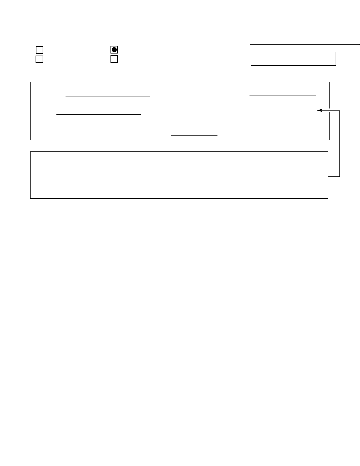
DS19330
Model:
COLOR TELEVISION
FILE NO.
Notice
CORRECTION
SERVICE FLASH
PRODUCTION CHANGE
ADD INFORMATION
Please add this notice to the Service Manual listed below.
REVISION 02
Category :
U.S.A. / CANADA
Destination:
June / 15 / 2003
Date:
19330-02
Effective from : Chassis No.
SS780042
REF : No.
NOTE: Match the Chassis No. on the unit’s back cover with the Chassis No. in the Service Manual.
If the Service Manual Chassis No. does not match the unit’s, additional Service Literature
is required. This chassis is similar to Chassis No. 19330-00, however, all Service Information
is given in this Notice for Chassis No. 19330-02 used in Model DS19330.
— 2 —
SAFETY PRECAUTIONS
WARNING: The chassis of this receiver has a floating
ground with the potential of one half the AC line voltage in
respect to earth ground. Service should not be attempted by
anyone not familiar with the precautions necessary when
working on this type of equipment.
The following precautions must be observed:
1. An isolation transformer must be connected in the power
line between the receiver and the AC line before any service is performed on the receiver.
2. Comply with all caution and safety-related notes provided on the side of the cabinet, inside the cabinet, on the
chassis, and the picture tube.
3. When replacing a chassis in the cabinet, always be certain
that all the protective devices are installed properly, such
as control knobs, adjustment covers, shields and barriers.
DO NOT OPERATE THIS TELEVISION RECEIVER
WITHOUT THE PROTECTIVE SHIELD IN POSITION AND
PROPERLY SECURED.
4. Before replacing the back cover of the set, thoroughly
inspect the inside of the cabinet to see that no stray parts
or tools have been left inside.
Before returning any television to the customer, the
service technician must perform the following safety
checks to be sure that the unit is completely safe to
operate without danger of electrical shock.
ANTENNA COLD CHECK
Remove AC plug from the 120 VAC outlet and place a
jumper across the two blades. Connect one lead of an ohmmeter to the jumpered AC plug, and touch the other lead to
each exposed antenna terminal (UHF and VHF antenna terminals). The resistance must measure between 1M ohm and
5.2M ohm. Any resistance value below or above this range
indicates an abnormality which requires corrective action.
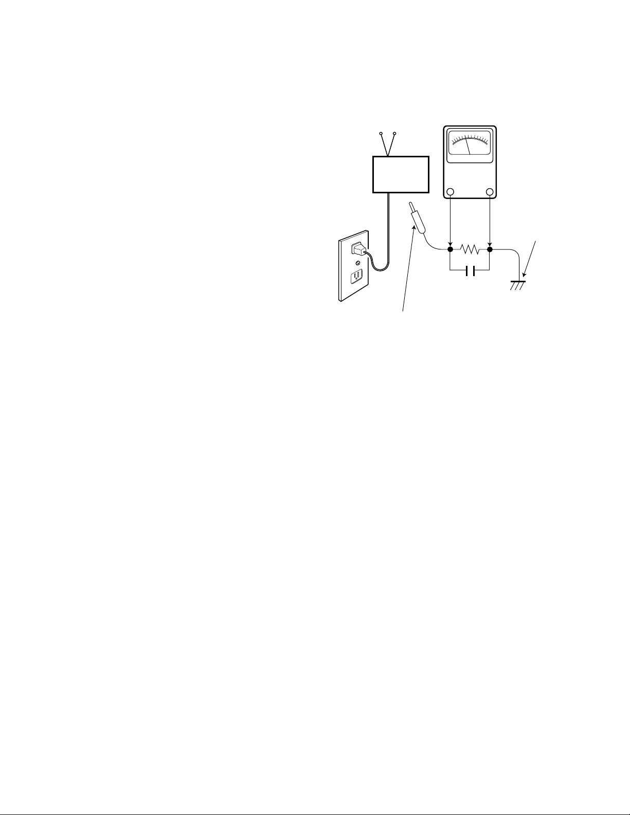
LEAKAGE CURRENT CHECK
Plug the AC line cord directly into a 120 VAC outlet. (Do not
use an isolation transformer for this check.) Use an AC voltmeter, that has 5000 ohms per volt or more sensitivity.
Connect a 1500 ohm 10 watt resistor, paralleled by a 0.15 µF
150 VAC capacitor, between a known good earth ground
(water pipe, conduit, etc.) and all exposed metal parts of the
cabinet (antennas, handle bracket, metal cabinet, screw
heads, metal overlays, control shafts, etc.). Measure the AC
voltage across the 1500 ohm resistor. The AC voltage
should not exceed 750 mV. A reading exceeding 750 mV
indicates that a dangerous potential exists. The fault must
be located and corrected. Repeat the above test with the
receiver power plug reversed.
NEVER RETURN A RECEIVER TO THE CUSTOMER
WITHOUT TAKING THE NECESSARY CORRECTIVE ACTION.
X-RADIATION PRECAUTION
The primary source of X-RADIATION in solid-state receivers is
the picture tube. The picture tube is specially constructed to
limit X-Ray emission. For continued X-RADIATION protection,
the replacement tube must be the same type as the original
(including the suffix letter in the part numbers). Excessive high
voltage may produce potentially hazardous X-RADIATION. To
avoid such hazards, the high voltage must be maintained within
specific limits. Refer to the X-RADIATION WARNING NOTE on
the CHASSIS SCHEMATIC in this service manual for specific
high voltage limits. If the high voltage exceeds specified limits,
check the components specified on the chassis schematic
diagram and take the necessary corrective action. Carefully
follow the instructions for the +B Voltage Check and the High
Voltage Check to maintain the high voltage within the specified
limits.
HIGH VOL T AGE HOLD-DOWN TEST
To prevent X-RADIATION from the picture tube due to
excessive high voltage, a HOLD-DOWN circuit is provided in
the high voltage circuit. Every time the receiver is serviced,
the high voltage HOLD-DOWN circuit must be tested for
proper operation. Refer to the HIGH VOLTAGE HOLDDOWN TEST in service adjustments.
PRODUCT SAFETY NOTICE
When replacing components in a receiver, always keep in
mind the necessary product safety precautions. Pay special
attention to the replacement of components marked with a
star (★) in the parts list and in the schematic diagrams. To
ensure safe product operation, it is necessary to replace
those components with the exact same PARTS.
SAFETY INSTRUCTIONS
READING SHOULD NOT EXCEED 750 mV.
AC VOLTMETER
(5000 ohms per volt or more sensitivity)
TELEVISION
RECEIVER
Good earth ground
such as a water pipe,
conduit, etc.
AC OUTLET
1500 ohm
10 watt
0.15 µF 150V AC
To be touched to all of exposed metal parts.
Voltmeter Hook-up for Leakage Current Check.
GENERAL
This set has an On-screen Service Menu system included in the CPU that allows remote operation for most of the service adjustments.
To enter the Service Menu, first disconnect the AC power cord. Then while pressing the MENU key on the front control panel, reconnect the AC power cord. The adjustments can now be made with the remote control or front control panel keys.
ON-SCREEN SERVICE MENU SYSTEM
1. Enter the Service Menu:
• While pressing the MENU key on the front control panel, reconnect the AC
power cord. The Service Menu Display will now appear. (See Figure 1.)
2. Service Adjustments:
• Press the ▲or ▼ key to select the desired service menu item you want to
adjust. (See page 4 for On-screen Service Menu.)
• Use the + or – key or number keys to adjust the data.
The + or – keys will increase or decrease the data sequentially.
The number keys (0 ~ 7) toggle only their respective bits between 1and 0.
3. Exit from the Service Menu:
• Press the MENU key to turn off the Service Menu display.
SERVICE AD JUSTMENTS
— 3 —
IC802 (EEPROM) REPLACEMENT
When IC802 (EEPROM) is replaced, IC801 (CPU) will automatically write the initial reference data into IC802 for basic TV operation.
However, the bus data should be checked and some bus data should be set up before attempting the service adjustments.
(See pages 4 – 5 for detailed information.)
INITIAL BUS DATA SETUP
Note:When IC802 (EEPROM) is replaced, change the following initial reference data for proper TV operation before
attempting the service adjustments.
1. Disconnect the AC power cord (AC 120V line).
2. While pressing the MENU key on the front control panel, reconnect the AC power cord.
The Service Menu display will now appear.
3. Select No. 3C SCO (Sub Color) with ▲ or ▼ key. Adjust the data with + or – key for 1D (hex).
4. Select No. 3D STI (Sub Tint) with ▲ or ▼ key. Adjust the data with + or – key for 08 (hex).
5. Select No. 3F SSH (Sub Sharpness) with ▲ or ▼ key. Adjust the data with + or – key for 05 (hex).
6. Select No. 42 VS (V Size) with ▲ or ▼ key. Adjust the data with + or – key for 45 (hex).
7. Select No. 43 VSP7VPO (V Sync Sep / V Position) with ▲ or ▼ key. Adjust the data with + or – key for 0F (hex).
8. Select No. 44 GRY7CRS5VLN (Gray / Cross B/W / V Lin) with ▲ or ▼ key. Adjust the data with + or – key for 92 (hex).
9. Select No. 45 HBL5VSC with ▲ or ▼ key. Adjust the data with + or – key for EA (hex).
10. Select No. 46 VC3CDM (V Size Comp / V Count Down), with ▲ or ▼ key. Adjust the data with + or – key for 38 (hex).
11. Select No. 4B BGS5RGD4GD (Bγ / RGγ / G Drive) with ▲ or ▼ key. Adjust the data with + or – key for 0B (hex).
12. Select No. 4D SBI (Sub Bias) with ▲ or ▼ key. Adjust the data with + or – key for 40 (hex).
13. Select No. 56 FBP6WP4PRE2CRG (FBP Blanking / White Peak / Pre shoot / Coring Gain) with ▲ or ▼ key. Adjust the data
with + or – key for 42 (hex).
14. Select No. 57 DCR4BSS2BSG (DC Reset / Black Stretch Start / Black Stretch Gain) with ▲ or ▼ key. Adjust the data with
+ or – key for 02 (hex).
15. Select No. 58 AFC7CBP5 (Auto Flesh / Color BPF Bypass) with ▲ or ▼ key. Adjust the data with + or – key for 80 (hex).
16. Select No. 60 HBL5 (H Blanking Left) with ▲ or ▼ key. Adjust the data with + or – key for 00 (hex).
17. Select No. 83 OPT (AV Option) with ▲ or ▼ key. Adjust the data with + or – key for 84 (hex).
18. Select No. 8D HR (H Display Position) with ▲ or ▼ key. Adjust the data with + or – key for 10 (hex).
19. Select No. 8E SBO (Sub Bright Offset) with ▲ or ▼ key. Adjust the data with + or – key for 00 (hex).
20. Press the MENU key to turn off the Service Menu display.
3C SCO
0A 00001010
Figure 1. Service Menu Display
ITEM NO.
TITLE
BINARY DATA
(8 bit)
HEX DATA
— 4 —
Table 1. ON-SCREEN SERVICE MENU
When IC802 (EEPROM) is replaced, check the bus data to confirm they are the same as below. The shaded menu should be
checked and be set up or readjusted according to the procedures described in the following pages. Initial Setup Data marked
with an * should be changed from Initial Reference Data. (See page 3 for Initial Bus Data Setup.)
No. TITLE
INITIAL REFERENCE INITIAL SETUP INITIAL SETUP
FUNCTION
DATA HEX DATA HEX DATA BINARY
3C SCO 0A 1D* 00011101 Sub Color
3D STI 05 08* 00001000 Sub Tint
3E SB 20 20 00010000 Sub Bright
3F SSH 12 05* 00000101 Sub Sharpness
40 AFC6HFR 9E 9E 10011110 AFC / Horizontal Frequency
41 HBS7HP 0F 0F 00010000 Horizontal Blanking / Horizontal Phase
42 VS 32 45* 01000101 Vertical Size
43 VSP7VPO 05 0F* 00001111 Vertical Sync Separator / Vertical Position
44 GRY7CRS5VLN 8E 92* 10010010 Gray Mode / Cross Black/White / Vertical Linearity
45 HBL5VSC EC EA* 11101010 Horizontal Blanking Right / Vertical S Correction
46 VC3CDM 28 38* 00111000 Vertical Compression / Vertical Count Down
47 RB 00 00 00000000 Red Bias
48 GB 00 00 00000000 Green Bias
49 BB 00 00 00000000 Blue Bias
4A RD 40 40 01000000 Red Drive
4B BGS5RGD4GD 08 0B* 00001011 Blue Gamma / Red-Green Gamma / Green Drive Reduction
4C BD 40 40 01000000 Blue Drive
4D SBI 20 40* 01000000 Sub Bias
4E ↓↓↓↓Not Used
4F ↓↓↓↓Not Used
50 OSD 01 01 00000001 On Screen Display Contrast
51 BSD7CR6 40 40 01000000 Black Stretch / Coring
52 ↓↓↓↓Not Used
53 ↓↓↓↓Not Used
54 FLS 01 01 00000001 Y/C Filter Mode
55 GYA3CKO 02 02 00000010 G-Y Angle / Color Killer Operation
56 FBP6WP4PRE2CRG 4A 42* 01000010 FBP Blanking / W Peak Limit / Preshoot Adj / Corring Gain
57 DCR4BSS2BSG 08 02* 00000010 DC Reset / Black Stretch Start / Black Stretch Gain
58 AFC7CBP5 00 80* 10000000 Auto Flesh / Color Band Pass Filter
59 DIG6ABL5MSD4BAT 04 04 00000100 OSD D/A / ABL Defeat / Mid Stop / ABL Threshold
5A RYA 02 02 00000010 R-Y/B-Y Angle
5B ↓↓↓↓Not Used
5C ↓↓↓↓Not Used
5D RAD 0F 0F 00001111 RF AGC Delay
5E FMM7IAS 00 00 00000000 FM Mute / IF AGC
5F VL5FL 67 67 01100111 Video Level / FM Level
60 HBL5 E0 00* 00000000 Horizontal Blanking Left
83 OPT 04 84* 10000100 AV Option (See Note 3)
84 OP2 00 00 00000000 Game / V-Guide Option (See Note 4)
8D HR 13 10* 00010000 Horizontal Display Position
8E SBO 03 00* 00000000 Sub Bright Offset
8F DRV
R40 R40 01000000 Red Drive Adjustment (See Note 1.)
B40 B40 01000000 Blue Drive Adjustment (See Note 1.)
– - - - Red Bias Adjustment (See Note 2.)
90 – - - - Green Bias Adjustment (See Note 2.)
– - - Blue Bias Adjustment (See Note 2.)
B0 ↓↓↓↓Not Used
↓↓ ↓ ↓ ↓↓
F8 ↓↓↓↓Not Used
— 5 —
PROGRAM CODE
The microprossesor used in this model is a multi-purpose
type and is used in several different models. To ensure
proper operation and the correct features for your
particular model, the Program Code must be correct.
Note 3.
Option Data (NO. 83 OPT) should be set to hexadecimal 84.
See page 3 INITIAL DATA SETUP step 17 for set up
procedure. If this program code is wrong the TV will not
operate properly.
Note 4.
Option Data (NO. 84 OP2) should be set to hexadecimal 00.
If this program code is wrong the TV will not operate
properly.
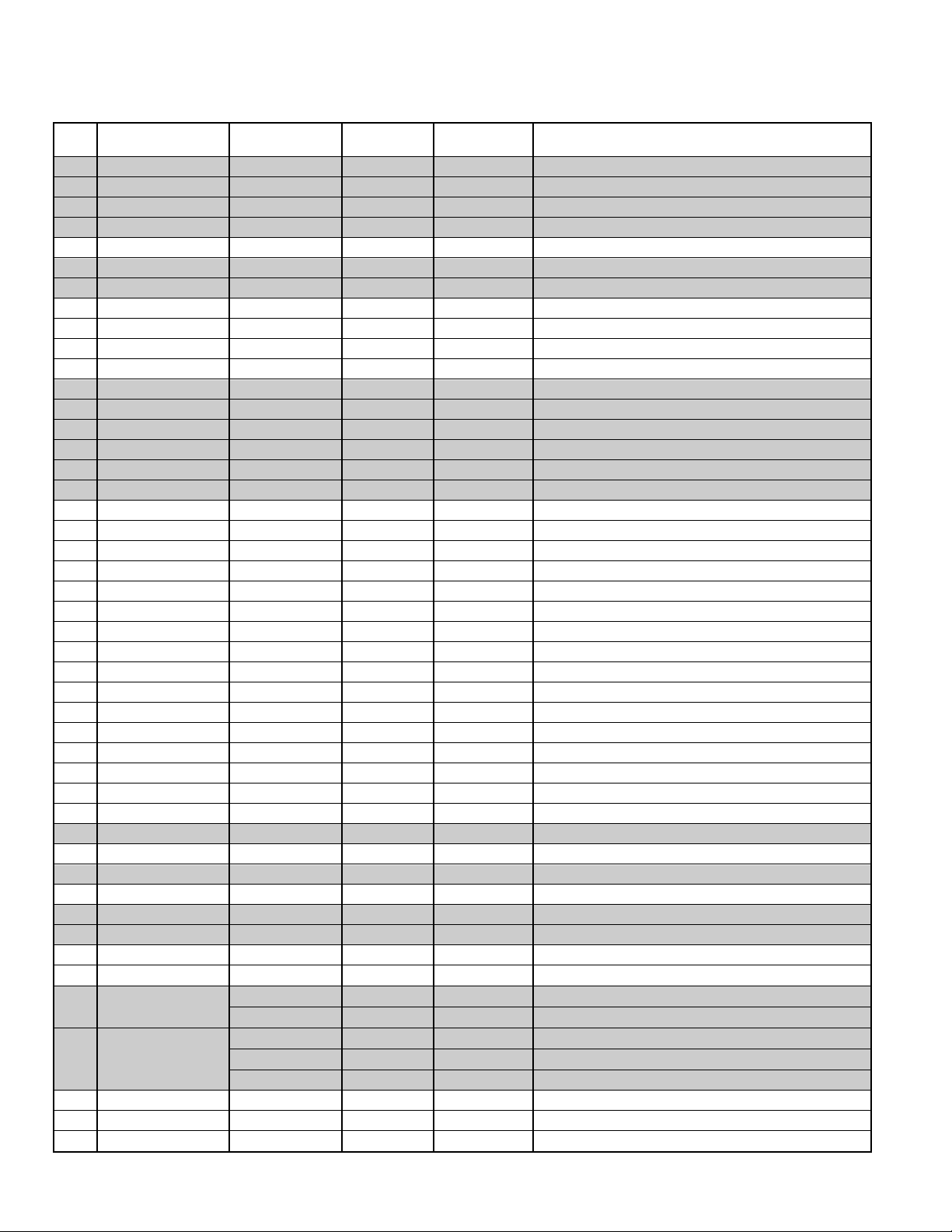
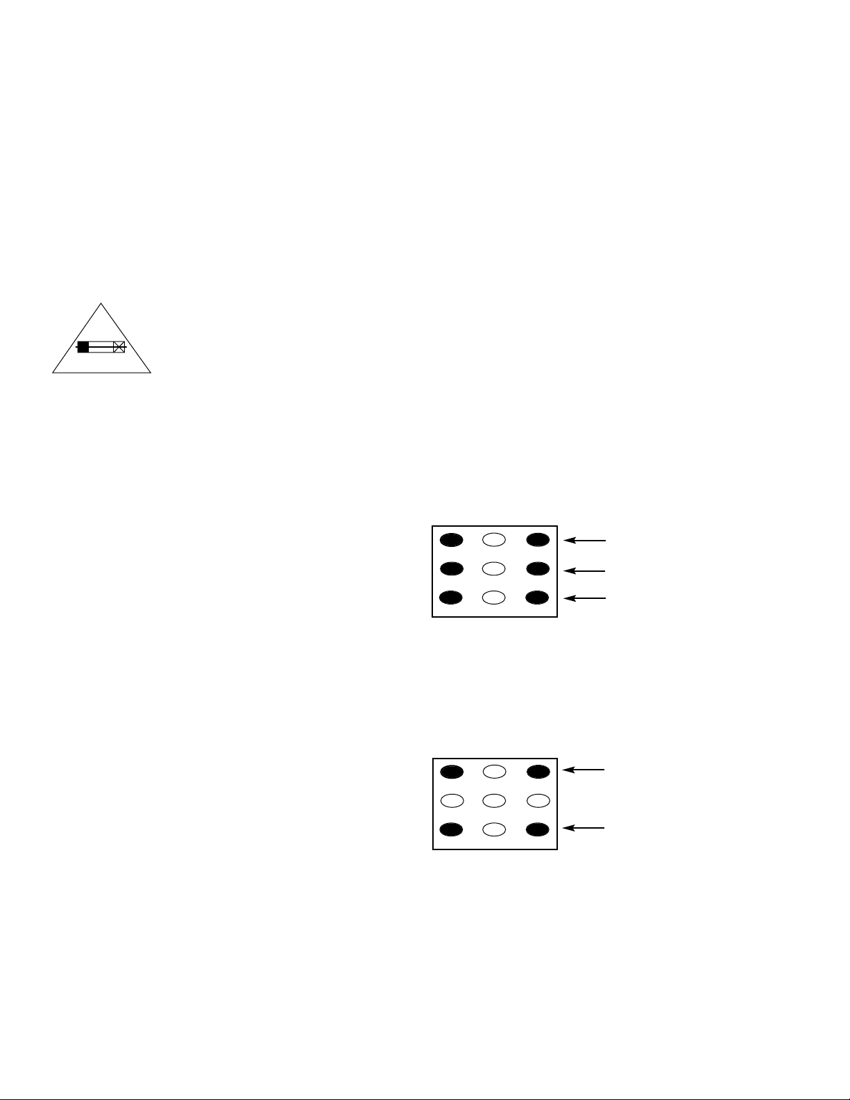
Note 1.
Red/Blue Drive Adjustments in Service Menu NO. 8F DRV:
Adjust Red and Blue Drive Levels alternately with 1, 3, 7,
and 9 keys on the remote control. (See Figure 1.) The Drive
Level adjustment data will be written in the Service Menu
No. 4A RD and 4C BD automatically.
1
2
3
4 5 6
7 98
RB(–)
RB(+)
BB(–)
BB(+)
(N/A)
GB(–)
(N/A)
GB(+)
(N/A)
FOR RED BIAS ADJUSTMENT
FOR BLUE BIAS ADJUSTMENT
FOR GREEN BIAS ADJUSTMENT
Figure 1.
Figure 2.
1
2
3
4 5 6
7 98
RD(–)
RD(+)
BD(–)
BD(+)
(N/A)
(N/A)
(N/A)
(N/A)
(N/A)
FOR RED DRIVE ADJUSTMENT
FOR BLUE DRIVE ADJUSTMENT
Note 2.
Red/Green/Blue Bias Adjustments in Service Menu
NO. 90:
Adjust each Bias Level with 1, 3, 4, 6, 7, or 9 key on the
remote control. (See Figure 2.) The Bias Level adjustment
data will be written in the Service Menu No. 47 RB,
No. 48 GB, and No. 49 BB automatically.
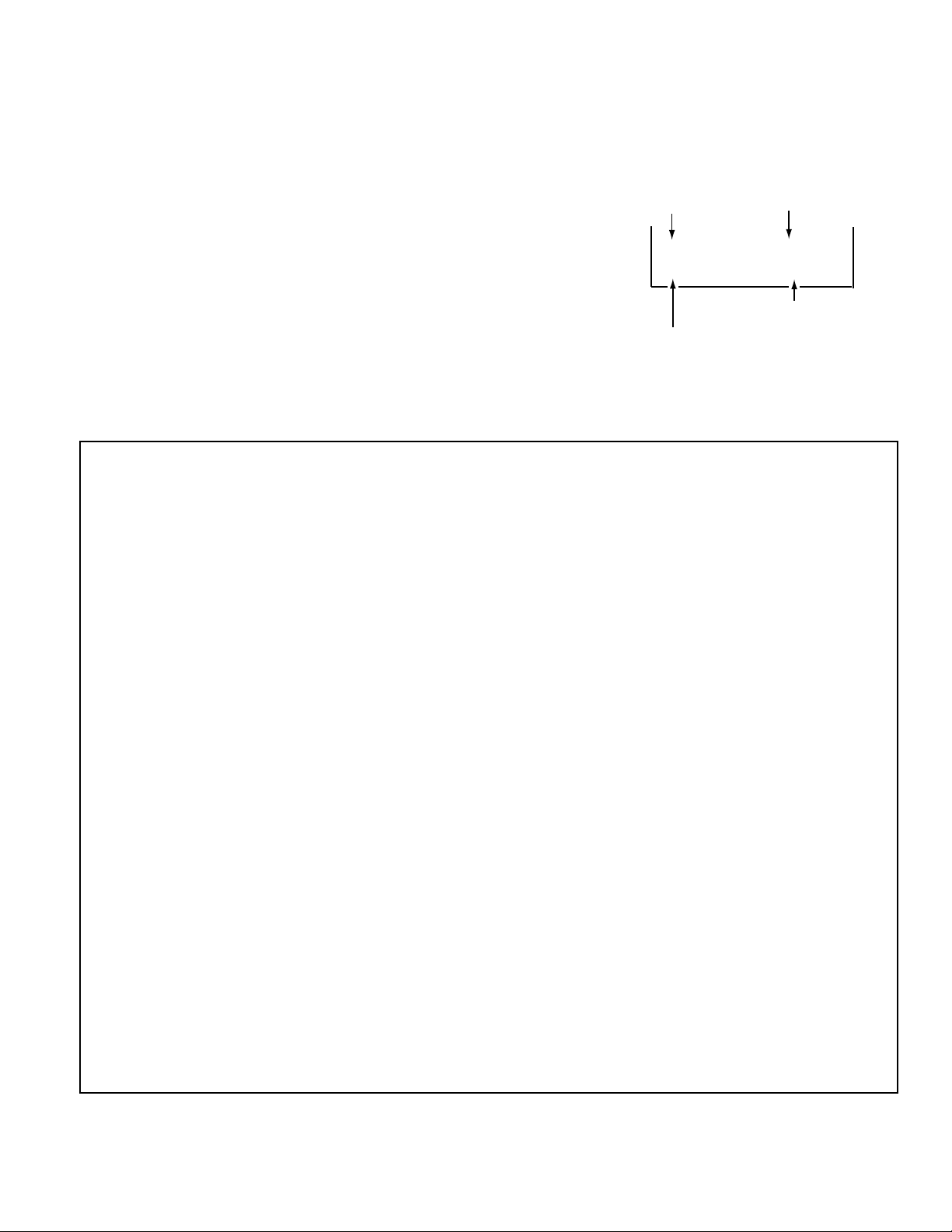
BIT FUNCTION
DATA
01
0, 1 NOT USED – –
2 AV FUNCTION NO AV AV
3 ~ 7 NOT USED
DRIVE AND BIAS ADJUSTMENTS
BIT FUNCTION
DATA
01
0 V–GUIDE YES NO
1 ~ 7 NOT USED – –
8 GAME MODE NO YES
SERVICE AD JUSTMENTS (Continued)
— 6 —
ANTENNA CONNECTIONS
This receiver is designed for UHF/VHF reception. A 75 ohm
terminal is provided for UHF and VHF receptions. When
connecting a CATV antenna system, connect the 75 ohm
coaxial cable directly to the 75 ohm terminal. For 300 ohm
VHF antenna, use an adapter (not included with the TV set).
CIRCUIT PROTECTION
Fuse F601 (4A) is included in the AC line. This fuse must be
replaced with the proper fuse (see Parts List).
+B VOL T AGE CHECK
Connect Voltmeter + lead to TJ1 135V and – lead to ground
(TE7). Connect receiver to AC 120V line. Tune receiver to an
active channel. Reset the picture controls to the AUTO
level. Voltage must measure between +133.0V and +137.0V.
If the voltage is out of this range, the power circuit must be
checked. No +B adjustment is provided on this chassis.
HORIZONTAL CENTERING ADJUSTMENT
1. Tune receiver to an active channel.
2. Check that picture is in the horizontal center of TV screen. If
picture is not centered horizontally, perform steps 3 ~ 6.
3. Turn off the receiver and disconnect the AC power cord
(120V AC line).
4. While pressing the MENU key, reconnect the AC power
cord. The Service Menu display will now appear.
5. Select NO. 41 HPS7HP (Horiz. Phase) with ▲ or ▼ key.
6. Adjust the data with + or – key for horizontal center. To
turn off the Service Menu display, press the MENU key.
VERTICAL SIZE ADJUSTMENT
1. Tune receiver to an active channel.
2. Check the vertical size of the picture. If the vertical size is
too large or small, perform steps 3 ~ 6.
3. Turn off the receiver and disconnect the AC power cord
(120V AC line).
4. While pressing the MENU key, reconnect the AC power
cord. The Service Menu display will now appear.
5. Select NO. 42 VS (Vertical Size) with ▲ or ▼ key.
6. Adjust the data with + or – key for full scan. To turn off
the Service Menu display, press the MENU key.
VERTICAL CENTERING ADJUSTMENT
1. Tune receiver to an active channel.
2. C heck that picture is in the center of TV screen. If picture
center is too low, add resistor R513 (470 ohm, 1W). If picture
center is too high, add resistor R512 (470 ohm, 1W).
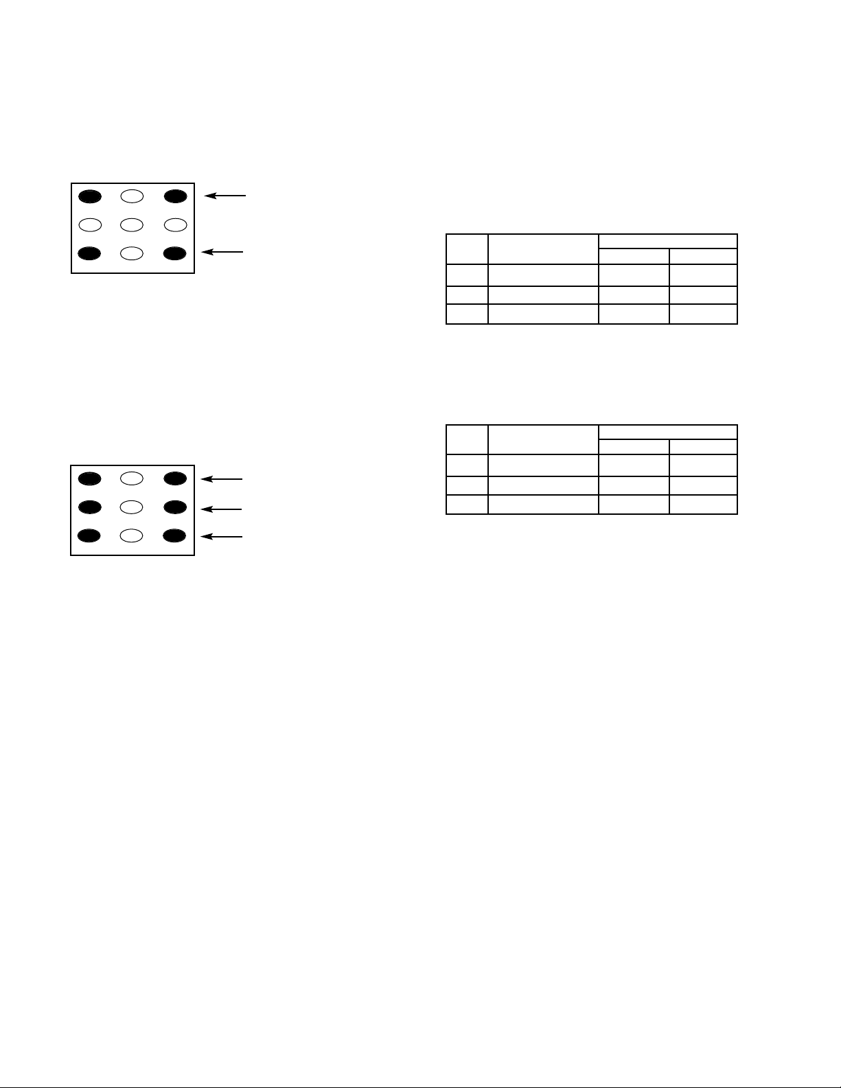
GRA Y SCALE ADJUS TMENT
1. Set the picture controls to the Auto levels (use MENU
key and ▲ or ▼ key or RESET key).
2. Turn off the receiver and disconnect the AC power cord
(120V AC line).
3. While pressing the MENU key, reconnect the AC power
cord. The Service Menu display will now appear.
4. Select NO. 47 RB (Red Bias), NO. 48 GB (Green Bias),
and NO. 49 BB (Blue Bias) with ▲ or ▼ key and set each
data to 00 with + or – key.
5. Select NO. 4A RD (Red Drive) and NO. 4C BD (Blue Drive)
with ▲ or ▼ key and set each data to 40 with + or – key.
6. Set NO. 3C SCO (Sub Color) data to 1D, NO. 3D STI (Sub
Tint) to 08, NO. 3E SB (Sub Brightness) data to 20, NO. 3F
SSH (Sub Sharpness) data to 05, and NO. 4B GD (Green
Drive Reduction) data to 0B with ▲ or ▼, and + or – keys.
7. Turn Screen Control (T402) to minimum (fully counterclockwise).
8. Select the Service Menu NO. 90 (Bias Adjustments – No
Vertical Sweep) with ▲ or ▼ key.
9. Advance Screen Control (T402) clockwise to obtain just
visible one color line. If line does not appear, place this
control to maximum (fully clockwise).
10. Raise each Bias Level with 3, 6, and 9 keys to obtain just
visible white line. (See Figure 4.)
11. Select the Service Menu NO. 8F DRV (Drive Adjustments)
with ▲ or ▼ key.
12. Adjust Red and Blue Drive Levels alternately with 1, 3,
7, or 9 key to produce normal black and white picture in
highlight areas. (See Figure 5.)
13. Check for proper grayscale at all brightness levels.
To turn off the Service Menu display, press the MENU key.
Note: If G rayscale Adjustment is made after picture tube
replacement, check Brightness Level Adjustment.
FOCUS ADJUSTMENT
Adjust focus control (T402) for well defined scanning lines.
CAUTION
FOR CONTINUED PROTECTION AGAINST
A RISK OF FIRE, REPLACE ONLY WITH
THE SAME TYPE 4A, 125V FUSE.
ATTENTION : POUR MAINTENIR LA PROTECTION CONTRE LES RISQUES
D’ INCENDIE UTILISER UN FUSIBLE DE
RECHANGE DE MEME TYPE 4A, 125V.
1
2
3
4 5 6
7 98
RB(–)
RB(+)
BB(–)
BB(+)
(N/A)
GB(–)
(N/A)
GB(+)
(N/A)
FOR RED BIAS ADJUSTMENT
FOR BLUE BIAS ADJUSTMENT
FOR GREEN BIAS ADJUSTMENT
Figure 4. Remote Control Number keys’ functions in
Service Menu NO. 90
1
2
3
4 5 6
7 98
RD(–)
RD(+)
BD(–)
BD(+)
(N/A)
(N/A)
(N/A)
(N/A)
(N/A)
Figure 5. Remote Control Number keys’ functions in
Service Menu NO. 8F DRV
FOR RED DRIVE ADJUSTMENT
FOR BLUE DRIVE ADJUSTMENT
4A 125V
 Loading...