

Page 1
_-i_ ¸_Si_ _ >_ _
_:_!!_ !ii_i_ O/i_ + W_/]_i_e _ %_i_¢%A_)I_O_,_A]_Oi!_ _,
Page 2
Important information
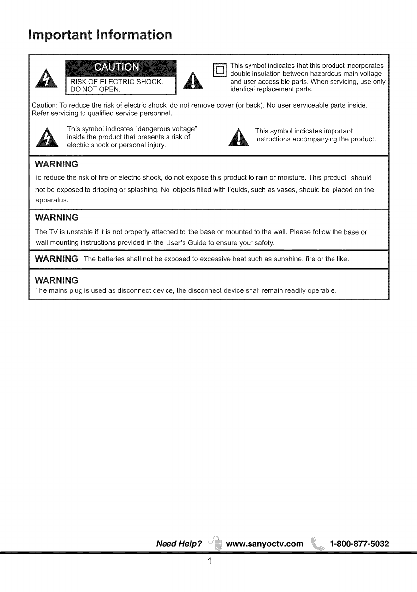
_ This symbol indicates that this product incorporates
,_ i _] _ _ double insulation between hazardous main voltage
Caution: To reduce the risk of electric shock, do not remove cover (or back). No user serviceable parts inside.
Refer servicing to qualified service personnel.
RISK OF ELECTRIC SHOCK. and user accessible parts. When servicing, use only
DO NOT OPEN. identical replacement parts.
,_ This symbol indicates "dangerous voltage"
inside the product that presents a risk of
electric shock or personal injury.
instructions accompanying the product.
This symbol indicates important
WARNING
To reduce the risk of fire or electric shock, do not expose this product to rain or moisture. This product should
not be exposed to dripping or splashing. No objects filled with liquids, such as vases, should be placed on the
apparatus.
WARNING
The TV is unstable if it is not properly attached to the base or mounted to the wall. Please follow the base or
wall mounting instructions provided in the User's Guide to ensure your safety.
WARNING The batteries shall not be exposed to excessive heat such as sunshine, fire or the like.
WARNING
The mains plug is used as disconnect device, the disconnect device shall remain readily operable.
NeedHelp? www.sanyoctv.com ;,,, 1-800-877-5032
1
Page 3
important Safety instructions
1. Read these instructions.
2. Keep these instructions.
3. Heed all warnings.
4. Follow all instructions.
5. Do not use this apparatus near water.
6. Clean onlywith dry cloth.
7. Do not block any ventilation openings. Install in accordance with the manufacture's
instructions.
8,
Do not install near any heat sources such as radiators, heat registers, stoves, or other
apparatus (including amplifiers) that produce heat.
g,
Do not defeat the safety purpose of the polarized or grounding plug. A polarized plug has
two blades with one wider than the other. Agrounding plug has two blades and a third
grounding prong. The wide blade or the third prong is provided for your safety. If the
provided plug does not fit into your outlet, consult an electrician for replacement of the
obsolete outlet.
10. Protect the power cord from being walked on or pinched particularly at the plugs,
convenience receptacles, and at the point where they exit from the apparatus.
11. Only use attachments/accessories specified by the manufacturer.
12. Use only with the cart, stand, tripod, bracket, or table specified by the manufacturer, or
sold with the apparatus. When a cart or rack is used, use caution when moving the
cart/apparatus combination to avoid injury from tip-over.
13. Unplug the apparatus during lightning storms or when unused for long periods of time.
14. Refer all servicing to qualified personnel. Servicing is required when the apparatus has
been damaged in any way, such as power supply cord or plug is damaged, liquid has been
spilled or objects have fallen into the apparatus has been exposed to rain or moisture,
does not operate normally, or has been dropped.
15. WARNING: To prevent injury, this apparatus must be securely attached to the floor/wall in
accordance with the installation instruction.
16. If an outside antenna or cable system is connected to the product, be sure the antenna or
cable system is grounded so as to provide some protection against voltage surges and built-up
static charges. Section 810 of the National Electrical Code, ANSI/NFPA No. 70-1984 (Section
54 of Canadian Electrical Code, Part 1) provides information with respect to proper grounding of
the mast and supporting structure, grounding of the lead-in wire to an antenna-discharge unit, size
of grounding conductors, location of antenna-discharge unit, connection to grounding electrodes,
and requirements for the grounding electrode. See following example:
NeedHelp? www.sanyoctv.com +++ 1-800-877-5032
2
Page 4
Important Safety Instructions
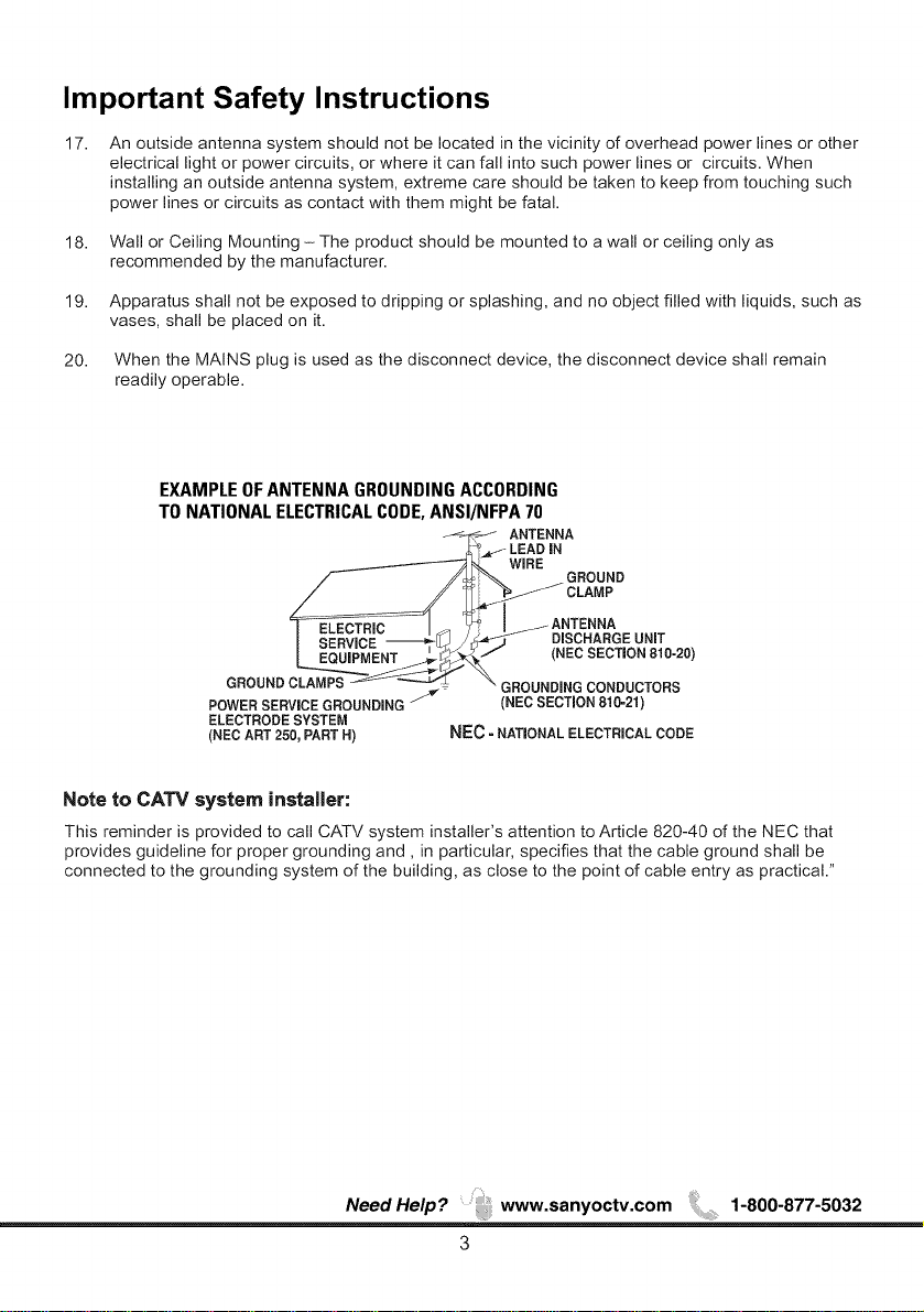
17.
An outside antenna system should not be located in the vicinity of overhead power lines or other
electrical light or power circuits, or where it can fall into such power lines or circuits. When
installing an outside antenna system, extreme care should be taken to keep from touching such
power lines or circuits as contact with them might be fatal.
18. Wall or Ceiling Mounting - The product should be mounted to a wall or ceiling only as
recommended by the manufacturer.
19. Apparatus shall not be exposed to dripping or splashing, and no object filled with liquids, such as
vases, shall be placed on it.
20. When the MAINS plug is used as the disconnect device, the disconnect device shall remain
readily operable.
EXAMPLE OF ANTENNA GROUNDING ACCORDING
TO NATIONAL ELECTRICAL CODE, ANSI/NFPA 70
ANTENNA
LEADiN
WiRE
GROUND
CLAMP
jANTENNA
I _i&R-_[_J /J_ DISCHARGEUNiT
I E_ENT _/_k-_/ (NECSECTION810-20)
GROUND ROUNDINGCONDUCTORS
POWERSERVICEGROUNDING (NEC SECTION 810=21)
ELECTRODESYSTEM
(NEC ART 250, PART H) NEC =NATIONALELECTRICALCODE
Note to CATV system installer:
This reminder is provided to call CATV system installer's attention to Article 820-40 of the NEC that
provides guideline for proper grounding and, in particular, specifies that the cable ground shall be
connected to the grounding system of the building, as close to the point of cable entry as practical."
Need Help? www.sanyoctv.com 1-800-877-5032
3
Page 5
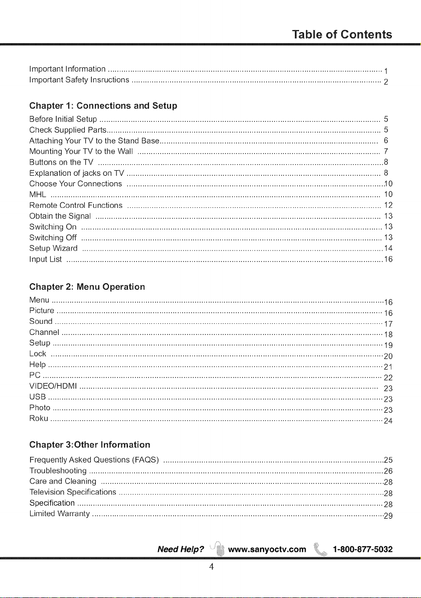
Table of Contents
Important Information ........................................................................................................................... 1
Important Safety Insructions ................................................................................................................ 2
Chapter 1: Connections and Setup
Before initial Setup .............................................................................................................................. 5
Check Supplied Parts ........................................................................................................................... 5
Attaching Your TV to the Stand Base .................................................................................................. 6
Mounting Your TV to the Wall ............................................................................................................. 7
Buttons on the TV ................................................................................................................................ 8
Explanation of jacks on TV .................................................................................................................. 8
Choose Your Connections ................................................................................................................... .10
MHL .................................................................................................................................................... 10
Remote Control Functions .................................................................................................................. 12
Obtain the Signal ................................................................................................................................ 13
Switching On ....................................................................................................................................... 13
Switching Off ....................................................................................................................................... 13
Setup Wizard ....................................................................................................................................... 14
input List .............................................................................................................................................. 16
Chapter 2: Menu Operation
Menu ..................................................................................................................................................... 16
Picture .................................................................................................................................................. 16
Sound ................................................................................................................................................... 17
Channel ................................................................................................................................................ 18
Setup .................................................................................................................................................... 19
Lock ..................................................................................................................................................... 20
Help ...................................................................................................................................................... 21
PC ........................................................................................................................................................ 22
ViDEO/HDMI ...................................................................................................................................... 23
USB ...................................................................................................................................................... 23
Photo .................................................................................................................................................... 23
Roku ..................................................................................................................................................... 24
Chapter 3:Other Information
Frequently Asked Questions (FAQS) ................................................................................................... 25
Troubleshooting .................................................................................................................................... 26
Care and Cleaning ............................................................................................................................... 28
Television Specifications ....................................................................................................................... 28
Specification ......................................................................................................................................... 28
Limited Warranty ................................................................................................................................... 29
NeedHelp? www.sanyoctv.com ,,, 1-800-877-5032
4
Page 6
Chapter 1 Connections and Setup
Before Initial Setup
Protect Aaainst Power Suraes
• Connect all components before you plug any power cords into the wall outlet or power strip.
• NEVER plug your TV into an outlet that is controlled by a wall switch.
• Turn off the TV before you connect or disconnect any cables.
• Make sure all antennas and cables are properly grounded. Refer to the Important Safety
Instructions.
Safety Information
• Protect components from overheating.
• Don't block ventilation holes on any of the components. Arrange the components so that air can
circulate freely.
• Don't stack components.
• If you place the component in a stand, make sure you allow adequate ventilation.
• If you connect an audio receiver or amplifier, place it on the top shelf so the heated air from it won't
harm other components.
Avoid Audio Interference
• Position cables properly; insert each cable firmly into the designated jack.
• If you place components above the TV, route all cables down one side of the back of the TV instead
of straight down the middle.
• If your antenna uses 300-ohm twin lead cables, do not coil the cables.
• Keep twin lead cables away from audio/video cables.
Avoid Direct Liqht
Don't place the TV where sunlight or room lighting is directed toward the screen. Use soft or indirect
lighting.
Check Supplied Parts
Check that the following parts were packed with your product.
• Remote Control
• User's Guide
• QUIK'N EASY Setup Guide
• Parts for Stand Base
Graphics contained within this publicationare presentation only.
NeedHelp? www.sanyoctv.com 1-800-877-5032
5
Page 7
Connections and Setup
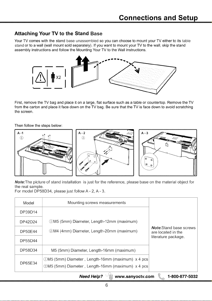
Attaching Your TV to the Stand Base
Your TV comes with the stand base unassembled so you can choose to mount your TV either to its table
stand or to a wall (wall mount sold separately). If you want to mount your TV to the wall, skip the stand
assembly instructions and follow the Mounting Your TV to the Wall instructions.
First, remove the TV bag and place it on a large, flat surface such as a table or countertop. Remove the TV
from the carton and place it face down on the TV bag. Be sure that the TV is face down to avoid scratching
the screen.
Then follow the steps below:
Note:The picture of stand installation is just for the reference, please base on the material object for
the real sample.
For model DP58D34, please just follow A - 2, A - 3.
Model
DP39D14
DP42D24
DP50E44
DP55D44
DP58D34
DP65E34
(J)M5 (5mm) Diameter, Length-12mm (maximum)
(z_'M4(4mm) Diameter, Length-20mm (maximum)
M5 (5mm) Diameter, Length-16mm (maximum)
(J)M5 (5mm) Diameter, Length-16mm (maximum) x 4 pcs
_z_'M5(5mm) Diameter, Length-16mm (maximum) x 4 pcs
Mounting screws measurements
Note:Stand base screws
are located in the
literature package.
NeedHelp? www.sanyoctv.com 1-800-877-5032
6
Page 8
Connections and Setup
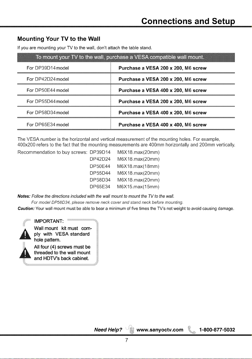
Mounting Your TV to the Wall
If you are mounting your TV to the wail, don't attach the table stand.
For DP39D14model Purchase a VESA 200 x 200, M6 screw
For DP42D24model Purchase a VESA 200 x 200, M6 screw
For DP50E44 model
For DP55D44model Purchase a VESA 200 x 200, M6 screw
For DP58D34model Purchase a VESA 400 x 200, IVl6 screw
For DP65E34 model Purchase a VESA 400 x 400, IVl6 screw
The VESA number is the horizontal and vertical measurement of the mounting holes. For example,
400x200 refers to the fact that the mounting measurements are 400mm horizontally and 200ram vertically.
Recommendation to buy screws: DP39D14
DP42D24
DP50E44
DP55D44
DP58D34
DP65E34
Notes: Follow the directions included with the wall mount to mount the TV to the wall.
For model DP58D34, please remove neck cover and stand neck before mounting.
Caution: Your wall mount must be able to bear a minimum of five times the TV's net weight to avoid causing damage.
Purchase a VESA 400 x 200, M6 screw
M6X 18.max(20mm)
M6X 18.max(20mm)
M6X18.max(18mm)
M6X 18.max(20mm)
M6X 18.max(20mm)
M6Xl 5.max(15mm)
IMPORTANT:
_ ply with standard
hole pattern.
All four (4) screws must be
Wall moUntVEsAkitmust com- ....
_ hreaded to the wall mount
and HDTV's back cabinet.
NeedHelp? www.sanyoctv.com ,,, 1-800-877-5032
7
Page 9
Connections and Setup
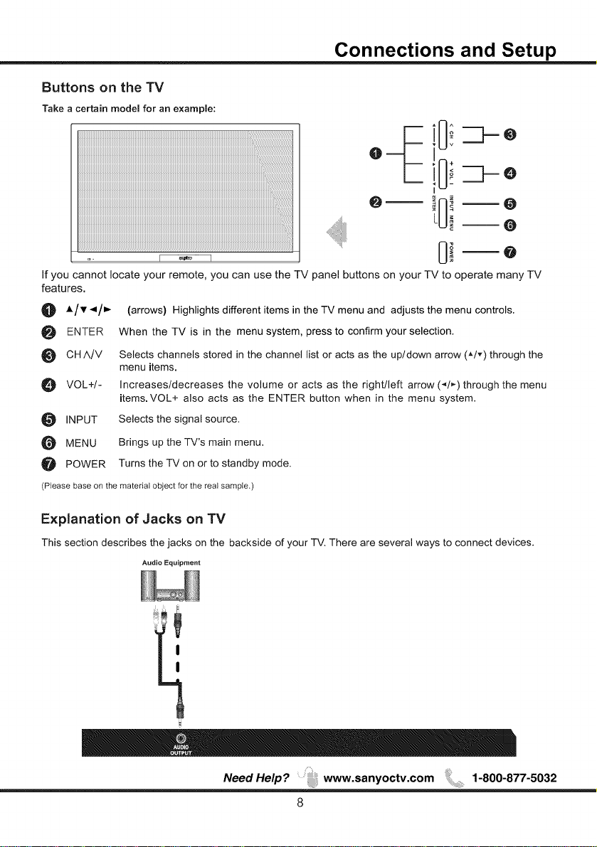
Buttons on the TV
Take a certain model for an example:
If you cannot locate your remote, you can use the TV panel buttons on your TV to operate many TV
features.
O A/v </_ (arrows) Highlights different items in the TV menu and adjusts the menu controls.
ENTER When the TV is in the menu system, press to confirm your selection.
O CH/k/V Selects channels stored in the channel list or acts as the up/down arrow (A/v) through the
O VOL+/- Increases/decreases the volume or acts as the right/left arrow (_,/,_) through the menu
O INPUT Selects the signal source.
MENU Brings up the TV's main menu.
POWER Turns the TV on or to standby mode.
(Please base onthe material objectfor the real sample,)
menu items.
items.VOL+ also acts as the ENTER button when in the menu system.
Explanation of Jacks on TV
This section describes the jacks on the backside of your TV. There are several ways to connect devices.
Audio Equipment
I
I
NeedHelp? www.sanyoctv.com ,,, 1-800-877-5032
8
Page 10
Connections and Setup
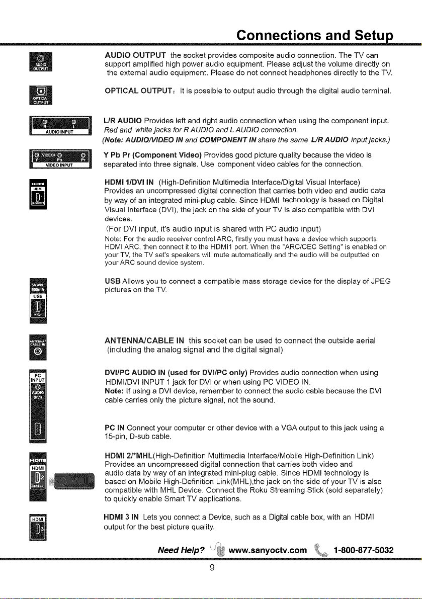
AUDIO OUTPUT the socket provides composite audio connection. The TV can
support amplified high power audio equipment. Please adjust the volume directly on
the external audio equipment. Please do not connect headphones directly to the TV.
OPTICAL OUTPUT: It is possible to output audio through the digital audio terminal.
L/R AUDIO Provides left and right audio connection when using the component input.
Red and white jacks for R AUDIO and L AUDIO connection.
(Note: AUDIO/VIDEO IN and COMPONENT IN share the same L/R AUDIO input jacks.)
Y Pb Pr (Component Video) Provides good picture quality because the video is
separated into three signals. Use component video cables for the connection.
HDMI I/DVI IN (High-Definition Multimedia Interface/Digital Visual interface)
Provides an uncompressed digital connection that carries both video and audio data
by way of an integrated mini-plug cable. Since HDMI technology is based on Digital
Visual Interface (DVl), the jack on the side of your TV is also compatible with DVl
devices.
(For DVl input, it's audio input is shared with PC audio input)
Note: For the audio receiver control ARC, firstly you must have a device which supports
HDMI ARC, then connect it to the HDMI1 port. When the "ARC/CEC Setting" is enabled on
your TV, the TV set's speakers will mute automatically and the audio will be outputted on
your ARC sound device system.
USB Allows you to connect a compatible mass storage device for the display of JPEG
pictures on the TV.
ANTENNA/CABLE IN this socket can be used to connect the outside aerial
(including the analog signal and the digital signal)
DVI/PC AUDIO IN (used for DVI/PC only) Provides audio connection when using
HDMI/DVI INPUT 1 jack for DVI or when using PC VIDEO IN.
Note: if using a DVI device, remember to connect the audio cable because the DVt
cable carries only the picture signal, not the sound.
PC IN Connect your computer or other device with a VGA output to this jack using a
15-pin, D-sub cable.
HDMI 2PMHL(High-Definition Multimedia Interface/Mobile High-Definition Link)
Provides an uncompressed digital connection that carries both video and
audio data by way of an integrated mini-plug cable. Since HDMI technology is
based on Mobile High-Definition Link(MHL),the jack on the side of your TV is also
compatible with MHL Device. Connect the Roku Streaming Stick (sold separately)
to quickly enable Smart TV applications.
HDM| 3 iN Lets you connect a Device, such as a Digital cable box, with an HDMI
output for the best picture quality.
Need Help? .... _ www.sanyoctv.com 1-800-877-5032
Page 11

Connections and Setup
Choose Your Connections
There are several ways to connect devices, such as DVD players and set-top boxes, to your TV.
Note: No cables are supplied with this unit. Please purchase the necessary cables. A high-speed HDMI cable
is recommended for better compatibility.
AntennalCable 480i, 480p, 720p, 1080i (NTSC, ATSC, and QAM formats)
Composite Video 480i
Component Video 480i, 480p, 720p/60Hz, 1OS0il60Hz, 1080p/60Hz
HDMI 480i, 480p, 720p/60Hz, 1080i/60Hz, 1080p/60Hz
PC VGA SVGA XGA WXGA
MHL2. 1 480i, 480p, 720p/60Hz, lO80it60Hz, lO8Opl3OHz, lO8Opl6OHz
MHL
HDMI 2 (*MHL)
O
The MHL (Mobile High-Definition Link) enables the TV to communicate with connected MHL-compatible
device. When connecting MHL-compatible device, TV simultaneously charges the connected device
while playing photo/music/video from it. You can use the TV remote control to control the connected MHL
-compatible device.
• If"MHL Equipment Contror'(P20) is set to "On", the TV automatically switches to MHL mode
when MHL-compatible device is connected to HDM112 (MHL)jack.
• You can continue normal usage of the connected MHL-compatible device (such as receiving calls)
depending on its capability.
• Some remote functions may not be available depending on features of the connected MHL-compatible
device.
Please refer to the device manual for details.
• You can continue charging the MHL-compatible device even when the TV is in standby mode.
_This product is officially MHL_certified for guaranteed operation with other MHL-certified devices. If you
encounter any problems when using the MHL function, please consult the device manufacturer for support.
NeedHelp? www.sanyoctv.com 1-800-877-5032
10
Page 12

Connections and Setup
VIDEO
/ \
Component Video Connection (Better) Composite Video Connection (Good)
|
VIDEO
I ............................ J
, AUDIO/VIDEO iNPUT
__,/
................................... w
PC Connection
VGA
PC VIDEO iN
cable
Audio l
AUDIO IN
DVI/PC
HDMI-DVm
Conversion
cable
DVI Connection
HDMI 1/DVIIN
DVI/PC
AUDIO iN
REMARK: Due to slim back cover, we recommend connecting the PC with a standard VGA
cable, avoiding cables with thicker connectors/plugs,
(For Model: DPSOE44, DP55D44, DP58D34, DP65E34)
NeedHelp? www.sanyoctv.com 1-800-877-5032
11
Page 13

Remote Control Functions
Connections and Setup
POWER
iNPUT
SUB CN=
RECALL
MENU
SMART
ENTER/OK
PICTURE
EXiT
VOL+/-
MUTE
CH^/V
USB
RESET
AUDIO
FAVORITE
SHAPE
SLEEP
INFO
Turns the TV on or standby.
Press to open the input list, then press •/_r to
select the desired option.
0-9
(Alphanumeric buttons) Enter a channel number, then
press ENTER (or let the entry timeout).
(dash) To enter a digital channel with a sub-channel,
enter the main channel, then press the dash button
(-) followed by the sub-channel, and then press the
ENTER button.
press the RECALL button return to the previously
viewed channel and replay for Roku.
Brings up the main menu or press to return to the
previous menu.
Return to the Home screen for Roku.
(arrows) Highlights different items in the TV menu and
adjusts the menu and Roku control.
When the TV is in the menu system, press to
confirm your selection.
Selects picture mode.
Removes any menu or display from the screen and
return to normal viewing.
Special function for Roku.
When using Roku, goes back to the previous screen.
Increases or decreases the TV volume.
Turns the volume on and off.
Selects channels and external input mode.
Goes to the USB menu.
Press to set factory setting.
Press to select your desired sound mode.
TV
Press to access to the TV mode.
Controls playback on Roku or playing photos in the USB
menu.
Press the FAVORITE button to browse the channels
in your favorite list. Use _,/v to highlight options, then
press ENTER to select.
PIX
Selects the desired screen format.
Sets the TV to turn off after a given amount of time.
If no menus are currently active, press INFO to display
the Channel information.
Noo,,o,p: ....,a.yoo,v.oom1-800-8,,-5032
12
Page 14

Connections and Setup
Obtain the Signal
The first step in connecting your TV is obtaining the signal. The back panel of your TV allows you to receive
analog and/or digital channels by using the ANT.75£_,
Connect the outside aerial or cable network to the
ANT.75D on the back of the TV set to ANT,75_
receive off-air channels or cable channnels.
• If you have a set-top box, you may need to call your
cable company or satellite service provider. They may
recommend special cables to allow you to view digital m
channels.
• The aerial socket (75 OHM - VHF / UHF / cable) can be
used for connecting an external aerial or other equipment
fitted with a modulator (video recorder, satellite receiver, etc.). RFCoaxial
We recommend that you do not connect other equipment Wire
(video recorder, satellite receiver, etc.) to your TV set to (75ohm)
begin with, so as not to complicate the set-up procedure
with the additional steps involved. Connect them when
you have finished setting up the channels.
• Visit www.antennaweb.orq for help in deciding what type of antenna to use in order to receive the local
digital channels available to you. Enter your location, and the program will list local analog and digital
stations available using your antenna.
Switching On
Follow the instructions on this page on how to switch on your TV set and use the remote control before going
on to following pages describing how to use the channel scan procedure.
1. Insert two AAA batteries in the remote control.
Precautions on using batteries:
- Only use the battery types specified.
- Make sure you use the correct polarity.
- Do not mix new and used batteries.
- Do not use rechargeable batteries.
- Do not expose batteries to excessive heat such as sunshine, fire or the like, throw them in a fire, recharge
them or try to open them, as this could cause them to leak or explode.
- Remove the batteries from the remote control if you are not using it for a long period of time.
2. Connect the power cable to a mains socket. (If the power cable is not connected to the television, please
first connect the power cable to the television.) Your TV set should only be connected to an AC supply.
tt must not be connected to a DC supply. If the plug is detached from the cable, do not, under any
circumstances, connect it to a mains socket, as there is a risk of electric shock.
3. When powered on, if the TV set is in standby mode, press POWER on the remote control or on the TV set
to turn on the TV.
I Outdoor or indoor Antenna
Or
Switching Off
To put the TV set into standby mode, press POWER on the remote control or on the TV, the TV set remains
powered up, but with low energy consumption.
To switch off the TV set, unplug the mains socket from the mains outlet.
NeedHelp? www.sanyoctv.com ;,,, 1-800-877-5032
13
Page 15

Connections and Setup
ENERGY STAR qualification. Use _1/_- to
select the desired location setting("Home
Mode or "Store Mode"); then press ENTER
/OK to continue to the next screen.
ENERGY STAR is a set of power saving
guidelines issued by the U. S.
Environmental Protection AgencyIEPA/.
ENERGY STAR is a joint program of the U.S.
Environmental Protection Agency and the
U.S.Department of Energy hemping us all
save money and protect the environment
through energy efficient products and
practices.
A menu screen asks you to select language among
English, French and Spanish.
Setup Wizard
Connect an RF cable to the TV's ANTENNA/CABLE
IN terminal.
Select TV Location
1.Press 4 /_. button on the remote control to select
Home Mode or Store Mode.
2. Press ENTER button to go.
Choose initial Setup method
1. Choose "Quick setup" or "Step by step" to setup
your new television.
2. Press ENTER button to go.
A menu screen asks you to set the location for TV.
Choosing"Home Mode" for the TV assigns the
optimal picture settings for most home
environments.
Choosing"Store Mode",which is not
ENERGY STAR compliant, sets the unit up
with predefined settings for retail displays.
In this setting, the power consumption may
exceed the requirements of the
Nee,,,e,,,; ....san,oc,v.com,-800-8,7-S032
If you choose "Quick setup", Please connect all
equipment to the TV's inputs and switch them on.
Then press 4/_- button to choose between an Air or
Cable search.
(Quick setup chosen)
14
Page 16

Connections and Setup
[Air]
Search channels form an indoor or outdoor antenna.
[Cable]
Search channels from the cable provider.
Press the Finish button to finalize the Initial Setup and
enjoy watching TV.
NOTE: If you need to do the process again, please
choose Repeat.
If "Step by step" is chosen, options will be more detailed.
Press Continue button to advance.
Press Next button to check connection in detail.
Press Repeat button to do the process again.
Press Continue button to go next.
(Setp by setp chosen)
Choose Antenna Information to get a high definition
picture, then press _/1_ button to choose between
an Air or Cable search.
Need Help ? www.sanyoctv.com 1-800-877-5032
If any connection is found, then you can see "Connection
was successful." with blue color.
15
Page 17

Chapter 2 Menu Operation
Picture
1. Press MENU to enter the main menu, Press_/
button to select.
2. Press T to enter. (Press MENU again to exit or
back to parent menu.)
3.While Picture Mode is "manual",Press_ IT button
to select among Picture ModelBrightnesslContrastl
Color / Tint I Sharpness I Color Temperature 1
Backlight/Detailed Settings.
Connections that are found will be highlighted in blue
color.
Press the Finish button to finalize the Initial Setup and
enjoy watching TV.
NOTE: If you need to do the process again, please
choose Repeat.
4.Press ENTERII_ to enter.
5.Press _/_ button to adjust.
6.Press MENU to exit it.
[Picture Mode]
Adjust picture mode to change picture appearance.
Press _ 1!_ button to select(Power SavinglStandard 1
Vivid 1Mild 1Manual).
input List
Press iNPUT button to select among TV/VlDEO
IHDMI IIHDMI 21HDMI 31PClUSB
Menu
1. Press MENU to display the main menu or return to
the previous menu or close the main menu.
2. Press _1/_-to highlight the desired menu icon, and
press T to enter.
NeedHelp? www.sanyoctv.com , 1-800-877-5032
Power Saving
Standard
Vivid Produces a highly defined image in a
Mild Produces a highly defined image in a
Manual Select to customize picture settings.
Note: "Power Saving"make this product qualify for
ENERGY STAR, if you select some other options,the
power consumption may change.
Items below are active while Picture mode
set to Manual. otherwise, they are gray.
[ Brightness]
Adjust darkness of black sections in the picture.
Press _l 1 I_ button to adjust.
Select to power saving mode settings.
Produces a highly defined image in a
normally lit room.
brightly lit room
soft lit room.
16
Page 18

Menu Operation
[ Contrast ]
Adjust the white level of the picture,
Press 4 / _ button to adjust,
[Color]
Adjust the color intensity of the picture.
Press4 / _ button to adjust.
[Tint]
Adjust the hue (Red,Green,Blue)of the picture.
Press 4 / _ button to adjusL
[Sharpness]
Obiect edges are enhanced for picture detail.
Press 4 / _. button to adjusL
[ Color Temperature ]
Change the overall color cast of the picture.
C> P'ed :ass ne te i a eo _a:;_:
[ Backlight]
Adiust the bacMight brightness
Press4 / _button to adjusL
[ Detailed Setting ]
Press _ button to enter.
® Aspect Ratio
Adjust how the picture MIs the screen.
W:,: .so tow_t d_, s_ _x It;:9
>tt} s_y_e s_t off
N _ ,;* A_tc*:_4ca y acj_ t Asp_ :tR_4c
ba edo_ [Vsze IV >o_ _
® Noise Reduction
Set options to reduce video noise.
Hig/ !i:e:ecta d (c (a e_ a ((c vitae
O;/ Select :s t_ o/video sos( dates( o
Law !/)erect as< ac ce ew vdeo ssose
/ca _
seaa
Enhanced Motion
Press 4 / !_ button to select (On / Off).
(Only available for model: DP50E44, DP55D44)
Motion Sync
Press 4 / I_ button to select (On / Off).
(Only available for model: DP58D34, DP65E34 )
Sound
1.Press MENU to enter the main menu, Press4 / !_
buttonto select.
2.Press T to enter. (Press MENU again to exit or back to
parent menu.)
3.Whib Sound mode is "manual", Press _, / _' button to
select among Sound Mode / Bass / Treble / Balance /
MTS /Audio Language / Digital Audio Output/Surround
Sound /ARC/CEC Setting /Auto Volume Control.
4.Press 41 / _ button to adjust.
5.Press MENU again or back to parent menu.
[MTS]
Configures the multi-track sound. It is only available inATV.
Press _ / _- button to select (Stereo/SAP/Mono),
_o :,vqu>< I<,:o_a
SAP S< u dses}( sate asesax: a(da
i_o a Setst a se sadema o
pogas
[Audio Language]
Select the language supported by the chosen digital
channel. It is available Only in DTV.
Press 4 1 _ button to select (English 1 French 1Spanish).
[Digital Audio Output ]
Send digital audio to external audio system,
Press _ / _ button to select.
W sss i f / o (
>( c e ; t cC i C
[Surround sound]
Press 4 / I_ button to select (On / Off).
saeo
[ ARC/CEC Setting ]
Press 4 / _ button to select (On / Off).
[Auto Volume Control ]
Set the auto volume control.
Press _1/ _ button to select (On / Off).
Sw sd re
Need Help? www.sanyoctv.com L}:L 1-800-877-5032
17
Page 19

Channel
1.Press MENU to enterthe main menu, Press 4 /
button to select.
2.Press _'to enter. (Press MENU again to exit or
back to parent menu.)
3.If current source is TV, Press ,L / T button to select
among Air/Cable/Auto Scan/Favorite / Channel List/
Show/Hide / Channel Number / Channel Label.
4.Press 4/!_ button to adjust.
5.Press MENU again or back to parent menu.
lAir/Cable]
Select signal type.
Press _ 1!_ button to select (AirlCable).
[Auto Scan]
Automatically search for channels.
Press ENTER/_ button to enter.
Menu Operation
[Show/Hide]
Show or hide the channels in your program list.
Press ENTER/_- button to enter.
[Channel Number]
Show the channel number.
Press 4 / I_ button to adjust.
[Channel Label]
Create labels for channels, up to 7 characters.
Press ENTER/ !_ button to enter.
[ Favorites ]
Add channels to create a favorite list.
Press ENTER/ _ button to enter.
[Channel List]
Create list for channels.
Press ENTER/ _ button to enter.
NeedHelp? www.sanyoctv.com 1-800-877-5032
18
Page 20

Setup
1.Press MENU to enterthe main menu, Press _1/1_
Button to select.
2.Press T to enter. (Press MENU again to exit or
back to parent menu.)
3.Press A / T button to select among Menu Language/
Closed Caption lOver Scanllnput Label 1
Other settings/Restore Default lSetup Wizard 1
Sleep Timer.
4.Press 4 1_ button to adjust.
5.Press MENU again or back to parent menu.
[Menu language]
Press _11 I_ button to select language (English 1
Frangais 1 Espadol.)
[Closed Caption]
Adjust Closed Captioning settings. Only available
under TV and AV source.
Press ENTER l !_button to enter.
Menu Operation
Mode
Set the look of digital Closed Captioning.
Press "_1 _ button to select (Default I Custom).
Font Style
Select from 8 font styles.
Press_/_ button to select (Default/Font0/Fontl/
Font 21Font 31Font 41Font 51Font 61Font 7).
Font Size
Adjust the size of the digital Closed Captioning font.
Press button to select (Default/Normal t Small/Large).
FG Color
Adjust the color of the digital Closed Captioning font.
Press 4 11_ button to select (Default/White IRed 1
Green 1Blue 1 Yellow I Magenta I Cyan).
BG Color
Adjust the digital Closed Captioning background color.
Press 4 11_button to select (Default/Black 1Red 1
Green IBluel Yellow I Magenta I Cyan).
FG Opacity
Adjust the transparency of the digital Closed Captioning
font.
Press 41 P, button to select (Default I Solid I Flashing 1
Translucent 1Transparent).
o CC Mode
Turn Closed Captioning onloff.
Press4/_buttontoselect(CCOff/CCOn/CC
On Mute).
• Analog CC
Set Closed Captioning for standard(analog) program.
Press _ 1 _ button to select (CCl 1CC21 CC31
CC41 Text11 Text21 Text31 Text4).
o Digital CC
Set Closed Captioning for digital program.
Press 4 1 _* button to select (Service11 Service21
Service31 Service41 Service51 Service61 Off).
® Option
Adjust the digital Closed Captioning setting.
Press ENTER/_button to enter.
NeedHelp? www.sanyoctv.com ,,, 1-800-877-5032
BG Opacity
Adjust the digital Closed Captioning background
transparency.
Press 4 /_, button to select (Default/Solid/
Flashing / Translucent / Transparent).
*Note: All the options can be adjusted while the
mode is Custom.
[Over Scan]
The setting of Over Scan onloff
Press 4 1_ button to select (Offl On).
[input Label]
Press ENTER 1_ button to enter.
19
Page 21

[Other Settings]
Press ENTER I_ button to enter.
o Blue Screen
The setting of Blue Screen onloff
Press 41!_ buttontoselect(OnlOff).
® AudioOnly
Play the audio with the picture turned off. When you
turn theAudio Only on and exit the OSD menu, the
panel will be dark; and then press any key(except
Mute key and VOL 4+ key) to exit the Audio Only
status.
Press 41_ button to select(Offl On).
® Video Setting
To relevant settings for video.
Press "_ / I_ button to select.
• Store Demo
About this TV set presentation.
Press _1_ button to select(Offl On).
• MHL Equipment Control
Press 41_ button to select(Offl On).
When "On" is selected, the HDMI2 source will auto-
matically be chosen when MHL equipment is
connected.
When "Off" is selected, the HDMI2 source will need
to be selected manually.
[Sleep Timer]
Set a timer for the TV to turn off automatically.
Press _ 1_ button to select(Offl5minll0min
115min 130min 160min 190min 1120min 1180min
1240rain).
Menu Operation
3.Enter your 4-dig ital password. Default password is
0000.
4.Press _ / _ button to select among Change Password /
System Lock I Input Block I US Rating 1Canada Rating 1
RRT Setting I Reset RRT.
5.Press _ /_ button to adjust.
6.Press MENU again or back to parent menu.
[Change Password]
Press the code the enter a new 4-digital password
then re-enter itto confirm.
[System Lock]
Lock or unlock the buttons on the TV.
Press _ / _ button to select(Off/On).
[ input Block]
Block or unbiock the input sources.
Press ENTER/_button to enter.
Press 4 / _ button to select(UnBIock / Block).
Lock
1.Press MENU to enterthe main menu, Press_ /_"
button to select.
2.Press _' to enter.(Press MENU again to exit or
back to parent menu.)
Need Help? www.sanyoctv.com 1-800-877-5032
[US Rating]
Restrict movie and TV programs by US Ratings.
Only available when "System Lock" is "on".
Press ENTER/_ button to enter.
2O
Page 22

Menu Operation
• TV
and content-based.
Age Define
TV-Y General audience
TV-Y7 Parental guidance suggested
TV-G Parents strongly cautioned
TV-PG Retricted
The TV rating compose of two aspects: age-based
TV-14 No one 17 and under admitted
TV-MA Adult audience only
Note: The content ratings will increase depending on
the level of the age-based rating.
For example, a program with a TV-PG V(violence)
rating may contain moderate violence, while a TV-14 V
(violence) rating may contain intense violence.
So locking a higher level option will automatically
cause locking the options that has more sensitive level.
• M PAA
This system defines the rating control which come
from MPAA rules.
Rating
G
PG
PG-13
R
NC-17
X
Define as
General audience. All ages admitted.
Parental guidance suggested. Some
material may not be suitable for children.
Parents strongly cautioned. Some
material may be inappropriate for children
under 13.
Restricted. Children under 17 require
accompanying parent or adult guardian.
No one 17 and under admitted.
Adult audience only.
Canada Engmish
These ratings are for programs which are using
English rating system.
Rating Defined as
C Children
C8+ Children 8 years and older
G General programming
PG Parental guidance
14+ Viewers 14 and older
18+ Adult programming
• Canada French
The ratings are for programs which are using
French rating system.
Rating Defined as
G General
8 ans+ Not recommended for children under
13 ans+ Not recommended for children under
16 ans+
18 ans+
[RRT Setting]
Display an advance V-Chip rating table for digital
channels.
The item is available only When current stream has
downloadable rating data.
[ Reset RRT]
Reset the RRT to default.
The item is available only When current stream has
downloadable rating data.
age 8
age 13
Not recommended for children
underage 16
This program is restricted to adults
Help
1.Press MENU to enterthe main menu, Press 4 / !_
button to select.
2rPress T to enter. (Press MENU again to exit or
back to parent menu r)
[Canada Rating]
Only available when "System Lock" is "on".
Press ENTER/I_ button to enter.
Restrict movie and TV programs by Canadian Ratings.
For Canada, the rating setting include the following options:
Canada English, Canada French.
Need Help? www.sanyoctv.com 1-800-877-5032
21
Page 23

Menu Operation
3.Press ENTER/_ to enter.
4.Press MENU to exit it
[Help]
Get help from the following choices.
Press _/_ button to select(Auto Recovery/
Self Test/Connection Guide/Antenna Guide /
Contact Us).
[Auto Recovery]
Quickly find which source has signal by auto
recovery page.
[Serf Test]
To test if the TV set is OK or not.
[Connection Guide]
To enter into a page for quick connection test.
[Antenna Guide]
To enter into antenna guide page,with the guide
page,you can conntect your antenna cable step by
step.
[Contact Us]
Some ways to contact us.
4.Press A / T button to select among H-Pos / V-Pos /
Clock I Phase 1Auto.
5.Press _ to enter.
6.Press _ / _, button to adjust.
7.Press MENU again or back to parent menu.
[H-Pos]
Adjust the horizontal position of the picture.
Press _ / _"button to adjust.
[V-Pos]
Adjust the vertical position of the picture.
Press_ / _ button to adjust.
[Clock]
Minimize vertical stripes in the screen image.
Press _ / _ button to adjust.
[Phase]
Minimize horizontal distortion.
Press _ / _ button to adjust.
[Auto]
Adjust to the PC signal timing automatically.
Press _, button to enter.
PC
1.Press mNPUT to select PC source.
2.Press MENU to enter the main menu, Press 4 /
button to select Setup menu.
3.Press _' to select PC Settings.
Need Help? www.sanyoctv.com 1-800-877-5032
*Note:
1. PICTURE menu and description are the same as that
for TV mode.
2. Audio Language in SOUND menu is invalid.
3. TIME menu and description are the same as that for
TV mode.
4.Close Caption in SETUP menu is invalid.
5.US, Canada, RRT Setting and Reset RRT in LOCK
menu is invalid.
6.PC mode has no CHANNEL menu.
22
Page 24

Menu Operation
VIDEO / HDMI
1. PICTURE menu and description are the same as that
for TV mode.
2. Audio Language in SOUND menu is invalid.
3. TIME menu and description are the same as that for
TV mode.
4.The function of Close Caption is available only in AVlTV
mode.
5.US, Canada, RRT Setting and Reset RRT in LOCK
menu is invalid.
6.Compositel COMPONENT 1HDMI mode has no
CHANNEL menu.
USB
*Note: Before operating Media menu, Plug inUSB
device, then press INPUT button to set the Input
Source to USB.
Press A / T button to select USB in the Source menu,
then press ENTER button to access.
Photo
I .Press INPUT button to display the input source list.
2.Press AI T button to select USB.
3.Press ENTER button to enter.
4.Press _ 1 I_ button to select drive disk you want to
watch, then press ENTER button to enter.
5.Press _ / _- button to select the file you want to watch
in the file selecting menu, then pressENTER button to
displaypicture.
Press ENTER button to enter.
*Note: Only support JPG format
Need Help? www.sanyoctv.com,,, 1-800-877-5032
23
Page 25

Roku
Menu Operation
1.Access the Roku. The Roku logo should appear after
a few seconds.
2.After Roku logo appears on screen, please wait
patiently for about a minute.
3. If Roku does not activate, please follow the
Roku network connection wizard.
Dual purpose HDIVll 2 input: Connect
the Roku Streaming Stick {sold
separately) to quickly enable Smart
TV applications like video streaming
and gaming or connect any standard
HDMI device. Find out more about
Roku Streaming Stick at
www, roku,com/sanyo
4. If Roku is successfully activated, the following
screen will appear.
Nee,,*,e,p:....,anyoctv.co.,1-800-877-S032
24
Page 26

Chapter 3 Other information
Frequently Asked Questions (FAQs)
What's the quickest way to view High Definition (HD) video?
Connect an off-air antenna to the ANT.75O to view free local digital channels. You may need to purchase an
antenna.
Visit www.antennaweb.orq for assistance in deciding what type of antenna to use to receive the local digital
channels available to you. By entering your location, this mapping program tells you which local analog and
digital stations are available using a certain antenna.
Are there other ways to view High Definition (HD) video?
Besides using an off-air antenna as mentioned above, you can also use a set-top box to receive
digital video. Contact your cable company or satellite provider to purchase digital programming
and have them connect the box to ensure you are viewing channels the best way.
Why are there bars on my screen and can t get rid of them?
Most digital video is sent in a 16/9 format which fills your screen, but is sometimes sent in 4/3 which does not
fill your screen. It depends on how the station or device connected to your TV is formatting the video. If there
are bars on the screen, press the PIX SHAPE button to try a different format that may eliminate the bars.
Some bars can't be removed because of the way the format is sent by the broadcaster. The format changes
as you press the PIX SHAPE button and the format type is displayed at the bottom of the screen.
Why does channel search find a lot of channels, but when I try to tune to them, there' s nothing
there?
Some channels enabled by the cable company don't carry programming, such as video ondemand. When
channels are unavailable, your TV screen is blank or appears like snow. You probably want to remove these
channels from your Channel List. Remove these in the Channel Skip Menu.
Why does the first channel search take a long time?
If you have both analog and digital channels, the TV is looking for all available channels in the Channel List. If
you do have digital channels, the TV is also searching for scrambled channels, non-scrambled channels, and
each sub-channel of that digital channel.
Need Help? www.sanyoctv.com 1-800-877-5032
25
Page 27

Other information
Troubleshooting
Most problems you encounter with your TV can be corrected by consulting the following troubleshooting list.
"IV Problems
The TV won't turn on,
• Make sure the TV is plugged in.
• Check the wall receptacle (or extension cord) to make sure it is "live" by plugging in another device.
There is no picture and no sound but the TV is on.
• You may be tuned to an input with no component connected to it. If you're trying to view a connected
component, press INPUT until the picture from that component appears.
• The Signal Type option may be set incorrectly.
• The channel may be blank. Try changing channels.
• If you're watching your VCR and it's connected with coaxial cable to the ANT.75£_ jack, tune the TV to
channel 3 or 4 (whichever channel is selected on the 3/4 switch on the back of your VCR). Also make
sure the TVNCR button on the VCR is in the correct mode (press the TVNCR button on your VCR).
The sound is fine, but the picture is poor quality.
• If you're getting a black and white picture from a component you've connected to your TV, you might have
your video cables connected to the wrong jacks. A yellow video cable connects to the yellow VIDEO
INPUT jack on the side or back of your TV; three video cables or bundled component video cables (red,
blue, and green) connect to the corresponding VIDEO iNPUT on the back of your TV.
• Check the antenna connections. Make sure all of the cables are firmly connected to the jacks.
There is no sound, but the picture is fine.
• The sound might be muted. Try pressing the volume up button to restore sound.
• If using DVI or Y, PB, PR, remember to also connect the device's left and right audio output jacks to the
TV's L and R AUDIO INPUT jacks.
• The sound settings may not be set correctly.
• If your audio source has only one jack or is a (mono) audio source, make sure you have plugged the
connection into the LAUDIO tNPUT jack on the -IV.
The screen is blank.
Check your connections. If you used Composite yellow, red, and white cables to connect, make
sure they're connected to the green VIDEO INPUT, and the red and white
• If you're trying to watch something that's playing on a component connected to the TV (like a DVD), press
INPUT until you get to the correct video input channel.
• Make sure the component connected to the TV is turned on.
• Try another channel.
The TV turns off unexpectedly.
• The electronic protection circuit may have been activated because of a power surge. Wait 30 seconds,
and then turn the TV on again. If this happens frequently, the voltage in your house may be abnormally
high or low.
• Unplug. Wait 10 minutes. Plug in again.
Need Help ? www.sanyoctv.com 1-800-877-5032
26
Page 28

Other information
You can't select a certain channel.
• The channel may be blocked or not approved in the Parental Control Menu_
• If using a VCR, check to make sure the TVNCR button on the VCR is in the correct mode (press the TV/
VCR button on your VCR).
• Press the TV button and then try to change channels.
The stereo reception is noisy.
• It may be a weak station. Use the Sound Menu andAnalog TV Sound to choose mono.
A black box appears on the screen.
• Closed captioning might be on. Check Closed Caption in the Setup menu.
You are having problems with the HDMI Connection.
• Make sure the HDMI or DVI component is turned on and the cables are firmly connected. If problems still
occur, turn off your component and reconnect it. Reset the power by unplugging the power cord and
plugging it back in.
• If you tune to the HDMI 1, or other HDMI INPUT and you see snow, the video goes in and out, or the
video takes a long time to appear, your HDMI or DVI component is having trouble sending video
information to the TV. Reconnect your device. Reset the power by unplugging the power cord and plugging
it back in. tf problems persist, try connecting the Y Pb Pr jacks if they are available or contact the
manufacturer of the HDMI or DVt component for further assistance.
• If you have black bars on each side of your picture, the component you connected might have a switch or
a menu option allowing you to change the picture quality output that will fix this. Choose either 720p or 1080i.
The remote control doesn't work.
• Something might be between the remote and the remote light sensor on the front of the TV. Make sure
there is a clear path.
• The remote may not be aimed directly at the TV.
• The batteries in the remote may be weak, dead, or installed incorrectly. Put new batteries in the remote.
The Universal Remote control doesn't work.
This TV utilizes new remote control signals and may not be compatible with your existing universal remote (e.g.
satellite box remotes, cable box remotes, and generic universal remotes, etc.). Over time, newer universal
remotes will become available that should pick up the new TV codes.
You are experiencing problems with V-Chip/Parental Controls.
If the rating limits don't work, you must lock the settings. Go to the Main Menu (press MENU on your remote),
select Lock > Enter Password >System lock, System lock Rating Enable is highlighted. Press 4/,- to select
On to have the rating limits take effect.
What else can I do?
If you've been through the Troubleshooting section and nothing has fixed your problem, try rebooting your
TV. Note that after a reboot, you may need to run your TV through the setup process again. To do a reboot,
unplug the power cord from the wall outlet or power strip. Keep your TV unplugged for about 5 minutes.
Then plug in the TV and turn it on. See if the problem is fixed. If the problem remains, then please visit www.
sanyoctv.com for updated FAQs or contact SANYO Customer Support at the support number provided in your
QNE guide or the number shown at the bottom of the page.
Nee ,,e,p?www.sanyootv.com1-800-877-S032
27
Page 29

Other information
Care and Cleaning
Caution: Turn OFF your TV before cleaning.
You can clean the TV as required, using a soft lint-free cloth. Be sure to occasionally dust the ventilation slots
in the cabinet to help assure adequate ventilation.
IMPORTANT: Never use strong cleaning agents, such as ammonia-based cleaners, or abrasive powder.
These types of cleaners will damage the TV. The TV's screen may be cleaned with a soft, lint-flee cloth as
well Take care not to scratch or mar the screen. If necessary, you may use a cloth dampened with warm
water. While cleaning, do not spray liquid directly on the screen, or allow liquid to run down the screen and
inside the TV. Also, never place drinks or vases with water on top of the TV. This could increase the risk of
fire, shock hazard or damage to the TV.
Television Specifications
Broadcasting system US System NTSC-M
ATSC standard (8VSB), QAM
Receiving Channels VHF2-13
UHF14-69
CATV 14-36 (A)-(W)
37-59 (AA)-(WW)
60-85 (AAA)-(ZZZ)
86-94 (86)-(94)95-99 (A-5)-(A-1)
100-135 (100)-(135)
01 (4A)
Tuner type Frequency synthesized
Screen refresh rate 60Hz (For Model: DP39D14, DP42D24, DP50E44, DP55D44)
120Hz (For Model: DP58D34, DP65E34)
Specification
Model Requirement Consumption
DP39D14 70 watts 20.51bs (w/stand) 35.0 (w/stand) 22.6 (w/stand) 7.3 (w/stand)
DP42D24 70 watts 23.81bs (w/stand) 38.1 (w/stand) 24.3 (w/stand) 7.3 (w/stand)
DP50E44 Source: 90 watts 41.41bs (w/stand)
DP55D44 110 watts 45.61bs (w/stand) 49.1 (w/stand) 30.7 (w/stand) 9.8 (w/stand)
DP58D34 160 watts 61.31bs (w/stand) 51.5 (w/stand) 33.0 (w/stand) 10.4 (w/stand)
DP65E34 140 watts 81.61bs (w/stand) 57.9 (w/stand) 36.3 (w/stand) 19.7 (w/stand)
NOTE: Dimensions are in inches
Power AC Power Weight Width Height Depth
35.0 (w/out stand) 20.8 (w/out stand) 3.6 (w/out stand)
38.1 (w/out stand) 22.6 (w/out stand) 3.6 (w/out stand)
44.5 (w/stand) 27.9 (w/stand) 9.1 (w/stand)
AC 120V, 60Hz 44.5 (w/out stand) 26.1 (w/out stand) 2.1 (w/out stand)
49.1 (w/out stand) 28.8 (w/out stand) 3.9 (w/out stand)
51.5 (w/out stand) 30.8 (w/out stand) 4.0 (w/out stand)
57.9 (w/out stand) 33.9 (w/out stand) 2.3 (w/out stand)
Need Help ? www.sanyoctv.com 1-800-877-5032
28
Page 30

ONE-YEAR LIMITED PARTS AND LABOR WARRANTY
THIS LIMITED PARTS AND LABOR WARRANTY IS VALID ONLY ON SANYO TELEVISIONS
PURCHASED AND USED IN THE UNITED STATES OF AMERICA, CANADA, AND PUERTO RICO, EXCLUDING ALL
OTHER U.S. TERRITORIES AND PROTECTORATES. THIS LIMITED WARRANTY APPLIES ONLY TO THE ORIGINAL
RETAIL PURCHASER, AND DOES NOT APPLY TO PRODUCTS USED FOR INDUSTRIAL OR COMMERCIAL
PURPOSES.
WARRANTY APPLICATION
FOR ONE YEAR from the date of original retail purchase Sanyo Manufacturing Corporation (SMC)
warrants this TV to be free from manufacturing defects in materials and workmanship under normal use
and conditions for parts and labor.
For the FIRST 90 DAYS from the date of original retail purchase, Sanyo Manufacturing Corporation
will replace any defective TV via exchange at the retailer. To ensure proper warranty application, keep
the original-dated-sales receipt for evidence of purchase. Return the defective TV to the retailer
along with the receipt and the included accessories, such as the remote control. The defective
TV will be exchanged for the same model, or a replacement model of equal value, if necessary.
Replacement model will be contingent on availability and at the sole discretion of Sanyo
Manufacturing Corporation.
THE FOREGOING WARRANTY IS EXCLUSIVE AND IN LIEU OF ALL OTHER WARRANTIES OF MERCHANTABILITY
OR FITNESS FOR A PARTICULAR PURPOSE.
OBLIGATIONS
For one year from the date of purchase, Sanyo Manufacturing Corporation warrants
this product to be free from defects in material and workmanship under normal use and
conditions. During the first 90 days under this warranty for any manufacturing defect or
malfunction Sanyo Manufacturing Corporation will provide a new TV via exchange at
the retailer.
HOW TO MAKE A CLAIM UNDER THIS WARRANTY
Please call 1-800-877-5032. Please be prepared to give us the television's model number
and serial number when you call. The model number and serial number are printed on a
label attached to the back of the unit.
For customer assistance, call toll free 1-800-877-5032.
This warranty expresses specific contractual rights; retail purchasers may have additional statutory rights
which vary from state to state.
(EFFECTIVE: March 1, 2007)
Your Sanyo HDTV is registered at the time of purchase,
please keep sales receipt for future reference.
For your protection in the event of theft or loss of this product, please fill in the information requested
below and KEEP IN A SAFE PLACE FOR YOUR OWN PERSONAL RECORDS.
Model No. Serial No.
(Located on back of unit) (Located on back of unit)
Purchase date Purchase Price
Where Purchased
Need Help? www.sanyoctv.com 1-800-877-5032
29
Page 31

H roll °
HEGH-DEF_NmO_MUL'nMEDIA_NTERFACE
_'_ DOLBY
DIGITAL
Manufactured under license from Dolby Laboratories, Doiby and the double-D symbol are trademarks of
Dolby Laboratories.
This product incorporates HDMI technology.
HDMI, the HDMI logo, and High-Definition Multimedia Interface are trademarks or
registered trademarks of HDMI Licensing LLC.
=',< I=tl Lo .MHL, Mobile High-Definition Link and the MHL Logo are trademarks or
registered trademarks of MHL Licensing, LLC.
FCC Information
This equipment has been tested and found to comply with the limits for a Class B digital device, pursuant to Part
15 of the FCC Rules. These limits are designed to provide reasonable protection against harmful interference in a
residential installation. This equipment generates, uses, and can radiate radio frequency energy and, if not installed
and used in accordance with the instructions, may cause harmful interference to radio communications. However,
there is no guarantee that interference will not occur in a particular installation. If this equipment does cause harmful
interference to radio or television reception, which can be determined by turning the equipment off and on, the user is
encouraged to try to correct the interference by one or more of the following measures:
• Reorient or relocate the receiving antenna.
• Increase the separation between the equipment and receiver.
• Connect the equipment into an outlet on a circuit different from that to which the receiver is connected.
• Consult the dealer or an experienced radio/TV technician for help.
This Class B digital apparatus complies with Canadian ICES-003.
This device complies with Part 15 of the FCC Rules. Operation is subject to the following two conditions: (1) this de-
vice may not cause harmful interference, and (2) this device must accept any interference received, including interfer-
ence that may cause undesired operation.
Warning: Changes or modifications to this unit not expressly approved by the party responsible for compliance could
void the user's authority to operate the equipment.
Please do not send any products to the California address listed in this manual or on the carton. This will only add
delays in service for your product.
SANYO Manufacturing Corp,
2001 Sanyo Avenue
San Diego, CA. 92154-6229 U.S.A.
Part No.: 72-39D14M-X93Z6
Need Help ? www.sanyoctv.com 1-800-877-5032
 Loading...