

Page 1
INSTRUCTION MANUAL
Micro Component System
CD
DC-DA1100
-12-
Page 2
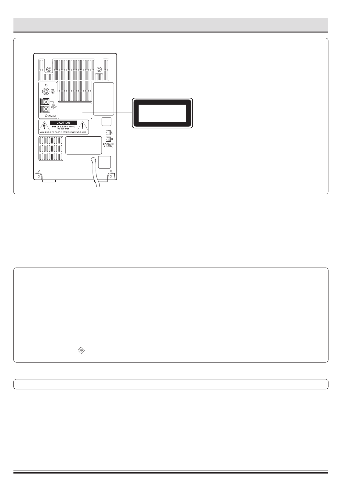
PRECAUTIONS
CAUTION
THIS PRODUCT CONTAINS A LOW POWER LASER DEVICE, TO
ENSURE CONTINUED SAFETY DO NOT REMOVE ANY COVERS
OR A TTEMPT TO GAIN ACCESS TO THE INSIDE OF THE PRODUCT.
REFER ALL SERVICING TO QUALIFIED PERSONNEL.
CLASS 1 LASER PRODUCT
LUOKAN 1 LASERLAITE
KLASS 1 LASERAPPARAT
- The apparatus shall not be exposed to dripping or splashing.
- Do not use where there are extremes of temperature (below 5°C or
exceeding 35°C) or where direct sunlight may strike it.
- Because of the CD player’s extremely low noise and wide dynamic
range, there might be a tendency to set the volume on the amplifier
unnecessarily high. Doing so may produce an excessively large
output from the amplifier which could damage your speakers.
IMPORTANT
If the plug supplied with this equipment is not suitable for the socket
outlets in your home it should be cut off and replaced with the correct
type.
Disposal of Plug
If the non rewireable plug is to be cut off, the removed plug should be
disposed of carefully as there is a shock hazard should the plug be
inserted into a live socket.
Replacing Fuse
The detachable fuse cover must be replaced after changing the fuse.
Only a 3A fuse should be used and should comply with BS1362 and
should carry the ASTA mark .
- Sudden changes in the ambient temperature may cause condensation to form on the optical lens inside the unit. If this happens, take out
the disc, leave the unit for about 1 hour, and then proceed to operate.
- The system’s speakers use powerful magnets. Do not place timepieces,
credit cards, cassette tapes or video tapes, etc. near the speakers.
- Do not install this equipment in a confined space, such as a book case
or built in cabinet.
- No object filled with liquids, such as vase, shall be placed on the
apparatus.
The wires in the mains lead are coloured in accordance with the following code;
Blue Neutral
Brown Live
The wires in the mains lead must be connected to the terminals in the
plug as follows;
Wire colour Plug terminal marking
Blue N or Black or Blue
Brown L or Red or Brown
Do not connect either wire to the earth terminal.
If the mains plug contains a fuse this should be 3A, if a plug without a
fuse is used the distribution board fuse should not be greater than 5A.
The unit is not disconnected from the mains unless it is unplugged from the AC outlet
-1-
Page 3
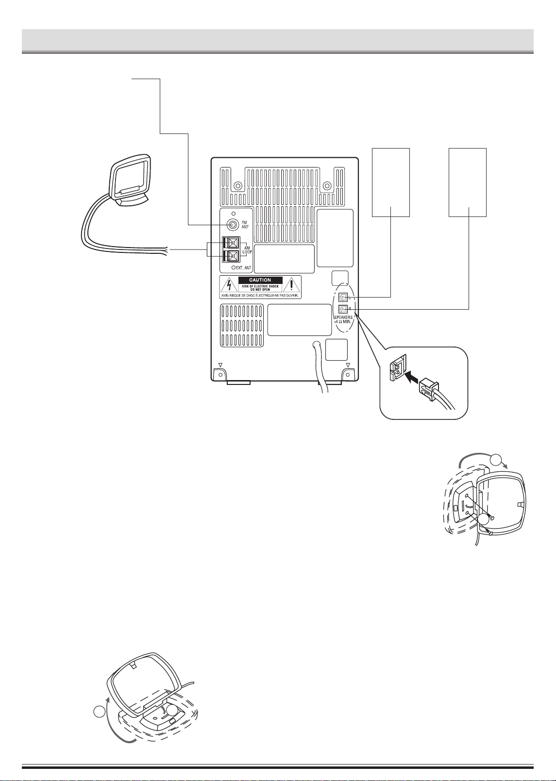
FM aerial
1
2
AM loop aerial
CONNECTIONS
R ch speakerL ch speaker
Note:
- Do not connect the mains lead to an AC outlet until all connections
have been made.
- The system is not completely disconnected from the mains when the
z/ON button is set to the z position.
Speakers
Connect the connector of the left speaker lead to the “L” SPEAKERS
socket and the connector of the right speaker lead to the “R” socket.
If you have difficulty inserting the speaker lead connector, turn it over
and reinsert it.
FM Aerial
FM indoor aerial is sufficient to receive broadcasts. Extend the aerial
wire as straight as possible and, while listening to the sound from the
system, secure it in a position which yields minimal distortion and noise.
AM Loop aerial
Assemble the loop aerial as shown in figure.
To an AC outlet
Unwind the aerial wires, then connect them
to the AM LOOP terminals. Place the loop
aerial in a position which yields the best
AM reception, or attach it to a wall or other
surface as shown in figure.
Note:
T o minimize noise, the speaker , mains and
any other leads should not come close to
the indoor or external aerial lead and AM
loop aerial. Do not place the aerial leads
close to the system.
Screws (not supplied)
Headphones
Connect stereo headphones (not supplied) to the PHONES socket for
monitoring or for private listening. The speakers are automatically disconnected when headphones are connected.
1
2
-2-
Page 4
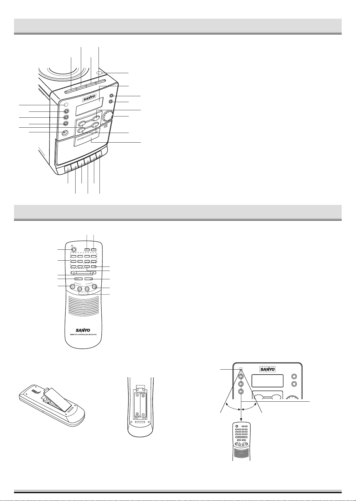
15˚ 15˚
CD
CONTROLS
11
9
161514
17
13
2
1
12
4
6
10
8
18
192021
22
23
7
CD player/Tuner/Generals
1. Remote sensor (IR)
2. Display
3. Tuner function/Band select button
(TUN/BAND)
4. Preset button (PRESET)
5. CD play/pause button (PLAY/PAUSE,
i)
6. Volume control (VOLUME)
3
7. Skip/Search/Tuning buttons
(f /TUN –, e /TUN +, SKIP/
5
24
SEARCH)
8. Headphones socket (PHONES)
9. CD stop button (STOP/n)
10. Memory button (MEMORY)
11. Function button (FUNCTION)
12. Power button (z/ON)
13. CD compartment open/close button
(CD OPEN/CLOSE)
14. Sound preset button (SOUND)
15. Bass expander button (BASS)
16. Surround button (SURROUND)
17. Clock/Timer button
(CLOCK/TIMER)
Cassette deck
18. Record button (REC)
19. Play button (PLAY)
20. Rewind button (REW)
21. Fast forward button (FFWD)
22. Stop/Eject button (STOP/EJECT)
23. Pause button (PAUSE)
24. Cassette holder
REMOTE CONTROL
Controls
1
12
11
10
Inserting batteries
/ON
1
234
5
678
9
0
VOLUME
MEMORY
- TUNE +
293
SLEEP FUNCTION
PRESET
FMMODE
/REPEAT
CD
TUNER
/BAND
4
5
6
7
8
1. Power buttons (z/ON)
2. Sleep button (SLEEP)
3. Function button (FUNCTION)
4. Tuner function/Band select button
(TUNER/BAND)
5. Preset tuning button (PRESET)
6. FM mode/Repeat button
(FM MODE/REPEAT)
7. Play/Pause button ( I )
8. Skip/Search/Tuning buttons
(F, E, – TUNE +)
9. Stop button ( N )
10. Memory button (MEMORY)
11. Volume buttons (– VOLUME +)
12. Number buttons (1-9, 0)
Remote control range
Remote sensor
12
Number buttons (1-9, 0)
These buttons are used to select the track
numbers on a disc or preset radio
stations.
If the function is “CD”, the buttons select
the track numbers on a disc.
If the function is “TUNER”, the buttons
select preset radio stations.
With any other function, the buttons will
not function.
- Two buttons must always be pressed.
Example:
To select No. 3, press 0, then 3.
To select No. 10, press 1, then 0.
To select No. 25, press 2, then 5.
Within approx.
7 meters
Note:
Always remove batteries if the remote control is not to be used for a
month or more. Batteries left in the unit may leak and cause damage.
Two R03/AAA batteries
(not supplied)
The buttons on the remote control perform similar functions to similarly
marked buttons on the front panel.
-3-
Page 5

ADJUSTING THE CLOCK (Main unit only)
Example: To set “6:30”,
First, press the z/ON button to turn the power off. Only the clock display
appears.
1. Press the CLOCK/TIMER button for
at least 2 seconds, “ 0 ” blinks on the
display.
2. Press the MEMORY button.
The hours display blinks.
3. Turn the VOLUME control to set the
“hours”.
4. Press the MEMORY button.
The minutes display blinks.
5. Turn the VOLUME control to set the
“minutes”.
6. Press the MEMORY button. The
clock starts.
- The time can be set accurately by pressing the MEMORY button
when a time signal is heard.
- To display the clock during operation, press the CLOCK/TIMER
button briefly. After a few seconds, the original display returns.
- If a power failure occurs or the mains lead is disconnected, the clock
display blinks. Reset the time again.
Changing the clock to the 12-hour display
1. Press the z/ON button to turn the power off and preset time display.
2. While clock is displaying, press the CD stop button on the main unit
and hold it, then press the BASS button on the top panel.
Example: 13:00 v PM 1:00
To return the original setting, repeat steps above.
BEFORE OPERATION
Turning the power on and off
Press the z/ON button. The display lights.
To turn the power off, press the z/ON button again, the clock display
remains lit.
- When the mains lead is connected to the AC outlet, the unit will
respond to commands from the remote control.
Direct start function
If the following buttons are pressed when the unit is in standby, the
unit turns on automatically and the function is set.
CD section i
Tuner TUN/BAND
Remote control I, TUNER/BAND
Selecting the function
Press the FUNCTION button to select the desired function. Each time
the button is pressed, the display changes as follows:
CD v TUNER v TAPE v CD v . . .
The function is automatically selected when CD play is started or when
the TUNER/BAND button has been pressed. (except during recording)
- When the function selection is changed, CD play is automatically
stopped.
Adjusting the volume
Turn the VOLUME control, or press the + or – VOLUME button on the
remote control. The volume level appears on the numbers. (VOL 0 ~
VOL 30).
Bass expander system
Press the BASS button to enhance the bass sound. “BASS” appears on
the display.
Selecting the sound mode
Press the SOUND button to select the sound mode matching the music
to be listened to.
POP: Pops, etc.
CLAS: Classical music, etc.
ROCK: Rock music, etc.
JAZZ: Jazz, etc.
WHAT TO DO IF ...
If the operation of the unit or display is not normal,
1. Press the z/ON button to set the main unit to standby mode.
2. Press the CD stop button and SOUND button on the unit at the same
time.
3. Press the z/ON button again to turn the power on.
4. Operate the unit.
Surround sound system
Press the SURROUND button. “SURR” appears on the display and a
“Wide” effect is created.
-4-
Page 6

CD PLAY
Use compact discs bearing the symbol shown. In addition to conventional 12 cm CDs, this system can be
used to play 8 cm CDs without an adapter.
- This unit can play back the CD-R/RW that have
recorded music data as well. However, some CD-R/RWs can not be
played back depending on the recording conditions.
- The CD-R/RW can’t be recorded in this unit.
1. Press the FUNCTION button to select “CD” function.
2. Press the CD compartment lid (Q CD OPEN/CLOSE portion). The CD
compartment opens.
3. Place the disc with the label facing up on the disc tray. (Place
only one disc at a time.)
4. Press the CD compartment lid
(Q CD OPEN/CLOSE portion) to
close it.
The total number of tracks and
total playing time on the disc appear.
Note:
If the disc is loaded with the label facing downward, or if a badly
scratched disc is loaded, “Cd” appears. If this occurs, load the disc
correctly or replace the damaged disc.
5. Press the i button. Play starts
from the first track.
The current track number and
elapsed playing time are
displayed.
6. Press the n button to end disc play.
When the last track has been played, the player stops automatically.
Note:
Always press the n button and wait for the disc to stop rotating before
opening the CD compartment.
Notes on handling compact discs
- Do not expose the disc to direct sunlight, high humidity or high
temperatures for extended periods of time.
- Discs should be returned to their cases after use.
- Do not apply paper or write anything on the disc surface.
- Handle the disc by its edge. Do not touch the playing surface (glossy
side).
- Fingerprints and dust should be carefully wiped off the playing surface
of the disc with a soft cloth.
Wipe in a straight motion from the centre to the outside of the disc.
- Never use chemicals such as record cleaning sprays, antistatic
sprays or fluids, benzene or thinner to clean compact discs.
To start play from the desired track
Select the track by using the e or f button, then press the i
button.
Using the remote control
Press two number buttons within 4 seconds. (Example: press 0, then 3.)
Temporarily stopping play
Press the i button. “ a ” blinks on the display. To resume play, press
the button again.
Search (forward/reverse)
If the E or F button is pressed during play, the player will search at
high speed in the forward or reverse direction while the button is being
pressed. When the button is released, normal play will continue.
Repeat play (Remote control only)
Press the FM MODE/REPEAT button before or during play. The player
will play all the tracks or all the programmed tracks repeatedly. “ ”
appears. To cancel repeat play, press the FM MODE/REPEAT button
again. “ ”disappears.
PROGRAMMED PLAY
Up to 20 tracks on a disc can be programmed for play in any order.
- First, select “CD” function and load a disc that you want to programme.
- The tracks must be programmed in the stop mode.
- The same track can be programmed more than once.
1. Press the MEMORY button.
2. Select a track by using the E or
F button.
- The number buttons on the remote control can also be used.
3. Press the MEMORY button.
4. Repeat steps 2 - 3 to programme additional tracks.
5. Press the i button to start programmed play.
When all programmed tracks have been played, the player stops
automatically.
- The programme contents are retained in memory.
- Any attempt to programme more than 20 tracks will result in “FULL”
being displayed and discontinuation of the programming.
- The programme contents are retained even if the function selection is
changed. After selecting “CD” function, press the MEMORY button.
The programmed contents appear.
- To cancel programmed play, press the n button twice.
Checking the programme
Each time the MEMORY button is pressed in the stop mode, the programmed details sequentially appear on the display.
Changing a programme
To add a new track to a programme:
1. In the stop mode, press the MEMORY button repeatedly until
“- -.- - - -” appears.
2. Select a track as explained above.
3. Press the MEMORY button.
To change a track:
1. In the stop mode, press the MEMORY button repeatedly until the track
number to be replaced is displayed.
2. Select a track as explained above.
3. Press the MEMORY button.
Note:
Programmed details cannot be partially deleted or inserted.
Skip play
T o skip to track 6 while track 3 is playing, press the e button repeatedly
until “6” appears (in the track section) on the display. To skip back to
track 3 while track 6 is playing, press the f button repeatedly until “3”
appears.
- The number buttons on the remote control can also be used for skip
play. To skip to track 6 while one track is playing, press 0, then 6.
-5-
Page 7

LISTENING TO TAPES
1. Press the FUNCTION button to select
“TAPE”.
2. Press the STOP/EJECT button to open
the cassette holder.
3. Load the cassette.
After loading the cassette, push the cassette holder back into position.
4. Press the PLAY button to begin playback.
5. Press the STOP/EJECT button to stop
playback at any time. Press it again to
remove the cassette.
When the end of the tape has been
reached, automatic stop will be activated.
LISTENING TO THE RADIO
Automatic/Manual tuning
1. Press the FUNCTION button to select “TUNER”. The radio frequency
appears.
2. Select the desired radio band with the TUNER/BAND button.
3. Automatic tuning
Press the TU UP or TU DOWN button for at least 1 second to tune in
a station. The unit will scan up or down the band and receive the next
receivable station. Press the button again to continue.
- The E or F button on the remote control can also be used.
Manual tuning
Press the TU UP or TU DOWN button briefly until the desired
frequency is displayed.
Note:
- Use the normal tape (TYPE 1).
- Endless tapes cannot be used.
- Do not use C-100 (or longer) tapes. They may jam in the mechanism.
Pause
Press the PAUSE button to temporarily stop playback or recording. Press
it again to resume operation.
Fast forward and rewind
Press the FFWD or REW button. When the desired location has been
reached, press the STOP/EJECT button.
Listening to preset stations
1. Press the TUNER/BAND button to select FM, MW or LW.
2. Press the PRESET button to select the desired channel number.
- The number buttons on the remote control can also be used.
Press two number buttons within 2 seconds.
Preset scan tuning
1. Press the TUNER/BAND button to select FM, MW or LW.
2. Press and hold down the PRESET button for at least 1 second.
- The preset stations are selected in sequence for approximately
five seconds each.
3. Press the PRESET button when the desired station has been selected.
Preset scanning will stop.
To preset stations
Up to 20 stations for FM band, 6 stations for MW band, and up to 6
stations for LW band can be preset.
1. Tune in the station to be preset as described above.
2. Press the MEMORY button.
3. While “PROG.” is blinking, press the PRESET button to select the
channel to be preset.
4. While “PROG.” is blinking, press the MEMORY button. “PROG.”
disappears.
- In this example, “103.25 MHz” FM station is preset on FM chan-
nel 9.
- The number buttons on the remote control can also be used. In
this example, press 0, then 9 after the step 2 above.
5. Repeat steps above to add more preset stations.
- When presetting a new station, the previous preset station is
cleared.
To receive FM stereo broadcasts
(Remote control only)
Make sure that “MONO” is not displayed. If “MONO” appears, press the
FM MODE/REPEAT button to turn the “MONO” indication off.
“ ST ” appears when an FM stereo broadcast is received.
- If the signal from an FM stereo station is weak and reception is poor,
press the FM MODE/REPEAT button to change to the MONO mode.
The reception may be improved, but the sound will be monaural.
-6-
Page 8

RECORDING
Recording copyright material without permission of the copyright owners is usually an infringement. If you wish to re-record copyright material,
permission from the copyright owner is necessary. SANYO does not
approve of, and cannot be held responsible for, any unlawful use of
this machine.
Recording compact discs (Synchronous recording)
1. Load a blank cassette.
2. Select “CD” function.
3. Load the disc to be recorded.
- Select the track number if required.
- For programmed recording, programme the material in advance
(as described under “PROGRAMMED PLAY”).
4. Press the REC button. The PLAY button is engaged simultaneously
and CD recording starts.
- When you want to record music as you listen, press the REC
button. Recording starts automatically from the beginning of the
track.
5. Press the STOP/EJECT button to stop recording.
When the end of the tape is reached, the CD player and deck stop
automatically.
Recording from the tuner
1. Load a blank cassette.
2. Tune in the radio station to be recorded.
3. Press the REC button to start recording.
4. Press the STOP/EJECT button to stop recording.
When beat is heard (Main unit only)
Beat (a high-pitched noise) may sometimes be heard during the recording of radio broadcasts. If this occurs, while the CD stop button is pressed,
press the BASS button at the same time to select bc-1 or bc-2. Select the
setting that gives the best result.
Safeguards against accidental erasure
Accidental erasure can be prevented by breaking out the tabs on the end
of the cassette tape (where the tape is not exposed) using a screwdriver
or similar implement.
If a tab is broken out in error and you wish to re-record the tape, simply
block the tab hole using adhesive tape and the tape can be used for
recording again.
Side A
Side B
Break out tab A for side A.
Break out tab B for side B.
-7-
Page 9

TIMER OPERATION
Using the timer (Main unit only)
Set the on and off times, and function to be used. Operation will start with
the selected function at the on time. The sound will be gradually increased
from a no-sound level to the current volume setting (fade-in). The power
will be switched off at the off time.
The timer will function every day unless it is released.
Note:
Make absolutely sure that the clock is set to the correct time before setting the timer.
Operation
1. Press the FUNCTION button to select the function and set the desired
volume level for timer operation.
2. Press the CLOCK/TIMER button for at least 2 seconds.
0
The previous timer on time setting appears.
3. Press the MEMORY button within 10 seconds.
0
4. Set the timer on time by turning the VOLUME control, then press the
MEMORY button (as described under “ADJUSTING THE CLOCK”).
00
To release the timer
After turning the power on, press the CLOCK/TIMER button twice, “ 0 ”
disappears.
To set the timer again with the same settings
1. Press the CLOCK/TIMER button repeatedly to display “ 0 ”.
2. Press the z/ON button to switch off the power.
Note:
The timer operation is released if a power failure occurs.
Using the sleep timer (Remote control only)
The sleep timer automatically switches off the power after a preset time
has elapsed. The volume will gradually be reduced (fade-out) during the
1-minute period before the unit turns off. There are 12 time periods
available: 120, 110, 100, 90, 80, 70, 60, 50, 40, 30, 20, and 10 minutes.
Press the SLEEP button repeatedly to select the desired sleep time.
“SLEEP” blinks and the selected time appears on the display. After a few
seconds, the original display returns. “SLEEP” remains blinking.
To check the remaining sleep time
Press the SLEEP button once. After a few seconds, the original display
return.
To release the sleep timer while in operation
Press the SLEEP button repeatedly until “SLEEP” disappears. The timer
is also released if the power is switched off.
The timer off time setting appears.
5. Set the timer off time as described in step 4.
0
The previous function setting appears.
-“ 0 ” remains lit.
6. Press the z/ON button to switch off the power.
- To switch off the power during a timer controlled operation, press
the z/ON button. The timer will be set in the standby mode.
0
-8-
Page 10

MAINTENANCE
Cleaning the tape heads
To ensure continued high performance, use cotton swab to clean the
heads, pinch roller and capstan of the deck after about every 10 hours of
use. If the dirt persists, soak the swab in a little methylated spirit or head
cleaning fluid and then clean.
1
2
543
1. Cotton swab
2. Capstan
3. Pinch roller
4, 5. Head
Cleaning the CD player lens
The lens should never be touched. If dust is on the lens, blow it off using
a camera lens blower. (Consult your dealer.)
Cleaning the unit
Clean the outside of the unit with a clean soft cloth, moistened with lukewarm water. Do not use benzene, thinner of alcohol since they will mar
the finish of the surfaces.
-9-
Page 11

SPECIFICATIONS
Tuner
Reception frequency:
FM: 87.5 - 108 MHz
MW: 522 - 1611 kHz
LW: 144 - 288 kHz
CD player
Channels:
2-channel stereo
Sampling frequency:
44.1 kHz
Pick-up:
Optical 3-beam semiconductor laser
Laser output:
0.6 mW (Continuous wave max.)
Wave length:
790 nm
Wow/flutter:
Below measurable limits
Cassette deck
Track system:
4-track, 2-channel stereo
Frequency response:
80 Hz to 15 kHz
Signal-to-noise ratio:
40 dB
Wow/flutter:
0.15% (WRMS)
Fast forward/rewind time:
Approx. 110 sec. (C-60)
General
Output power:
4 W x 2 (at 4 ohms, 10% distortion)
Outputs:
SPEAKERS: 4 ohms
PHONES: 8 - 32 ohms
Power requirements:
AC 230 V, 50 Hz
Power consumption:
21 W
Dimensions:
141(W) x 212(H) x 210(D) mm
Weight:
2.2 kg
Speaker systems
Type:
Full range bass reflex
Maximum power-handling capacity:
6 W (peak)
Nominal impedance:
4 ohms
Dimensions:
140(W) x 210(H) x 173(D) mm
Weight:
1.1 kg (per speaker)
Specifications subject to change without notice.
-10-
Page 12

GUARANTEE TO CUSTOMER
Sanyo Europe Ltd. (the Company) guarantees to the initial retail purchaser that if this equipment is or becomes defective and that, in the
opinion of the Company, the defect is due to faulty material or workmanship the Company will, for a period of 12 calendar months from the
date of sale to the original purchaser repair or replace, at its sole option,
free of charge, any such defective component part of the equipment,
always provided that:-
1. The equipment has at all times been used in accordance with the
operating instructions issued by the Company, and has not been connected to an electrical mains supply for which it has not been adjusted.
2. Accidental damage, or damage caused by negligence or misuse by
the user, including leakage from exhausted batteries, is specifically
excluded.
3. Unauthorized repairs, or any modification to the equipment which
has not been expressly approved by the Company, shall render this
guarantee null and void.
4. Failure due to fair wear and tear of any item, such as batteries,
record playing styli, and tape recording, playback and erase heads is
specifically excluded.
This guarantee is not transferable and is only applicable within the
United Kingdom (and the Republic of Ireland). Nothing in this express
guarantee affects the statutory rights available to the purchaser of this
equipment.
Note: This guarantee supersedes any other form of guarantee that
may inadvertently have been enclosed with or attached to the product.
(August 1978).
Thank you for buying Sanyo. This equipment should give you many
years of pleasure and faithful service but in the event that a fault occurs,
the following notes for your guidance may be helpful:-
1. PLEASE RETAIN YOUR PURCHASE RECEIPT WHICH WILL BE
REQUIRED FOR SERVICE DURING GUARANTEE.
2. If your Sanyo equipment proves faulty during the period of guarantee, take it or send it back to the dealer who originally supplied it together with this guarantee and the proof of purchase. We have made
arrangements with our approved dealers under which they will carry
out in-guarantee service repairs on our behalf. In this way, we hope to
reduce to a minimum the amount of time you will be without your
equipment.
3. If for some reason it is impossible to return the equipment to the
original supplier , please contact our Consumer Relations Department
at the address below for further advice.
4. Should the equipment require servicing after the expiry of the guarantee period, take or send it to the original supplier or any other Sanyo
dealer. He will be pleased to give you a quotation for the repair. If you
are in any doubt about what to do, write to us at the address below or
telephone:
Consumer Relations Department,
Sanyo Europe Ltd.,
Sanyo House
Otterspool Way, Watford,
Hertfordshire WD2 8JX
Tel: Watford 246363
R5
(UK) 1AD6P1P1988-- SANYO Electric Co., Ltd.
-11-
 Loading...