

Page 1
SERVICE MANUAL
2-WAY ECO-i
CHDX07263
CHDXR07263
CHDX09663
CHDXR09663**
Outdoor Units
C
ECO-i W-2WAY
Refrigerant R410A is used in the outdoor units.
* Salt-Air Damage Resistant Specifications.
Indoor Units
4-Way Air Discharge
X
Semi-Concealed
4-Way Air Discharge
XM
Mini Semi-Concealed
1-Way Air Discharge
A
Semi-Concealed
Concealed Duct Type
U
Slim Concealed
UM
Duct Type
Concealed-Duct High
D
Static Pressure
Ceiling-Mounted
T
CHDX07263
CHDXR07263
7
AHX0752
UHX0762
UMHX0762
**
9Class
AHX0952
UHX0962
UMHX0962
9672Class
CHDX09663
CHDXR09663
12 15 18 2419 36 48 54
XHX1252
XMHX1252
AHX1252
UHX1262
UMHX1262
THX1252
UHX1562
UMHX1562
XHX1852
XMHX1852
UHX1862
UMHX1862
THX1852
MULTI SYSTE
XHX2452
UHX2462 UHX3662 UHX4862 UHX5462
THX2452
XHX3652
DHX4852DHX3652
M
Wall-Mounted Type
K
Floor-Standing Type
F
Concealed-Floor
FM
Standing Type
**
Necessary to install the External Electronic Expansion Valve Kit (Optional:ATK-SVRK56BA).
85464849280000
KHX0752 KHX0952
FHX0762 FHX0962
FMHX0762
FMHX0962
KHX1252
FHX1262
FMHX1262
FHX1562
FMHX1562
KHX1962KHX1862
FHX1862
FMHX1862
KHX2452
**
FHX2462
FMHX2462
REFERENCE NO.
SM830180-00
Page 2
Please Read Before Starting
This air conditioning system meets strict safety and operating standards. As the installer or service person, it is an
important part of your job to install or service the system so
it operates safely and efficiently.
Carefully read this instruction booklet before beginning.
Follow each installation or repair step exactly as shown.
Observe all local, state, and national electrical codes.
This symbol refers to a hazard or
unsafe practice which can result
in personal injury or product or
property damage.
In Case of Improper Installation
When Wiring
ELECTRICAL SHOCK CAN CAUS
SEVERE PERSONAL INJURY OR DEATH.
ONLY A QUALIFIED, EXPERIENCED
ELECTRICIAN SHOULD ATTEMPT TO
WIRE THIS SYSTEM.
E
• Do not supply power to the unit until all wiring and tubing
are completed or reconnected and checked.
• Highly dangerous electrical voltages are used in this system. Carefully refer to the wiring diagram and these
instructions when wiring. Improper connections and inadequate grounding can cause accidental injury or death.
•
When Installing…
…In a Room
Properly insulate any tubing run inside a room to preven
“sweating” that can cause dripping and water damage to
walls and floors.
t
…In Moist or Uneven Locations
…
…In a Snowy Area (for Heat Pump-type Systems)
Install the outdoor unit on a raised platform that is higher
than drifting snow. Provide snow vents.
•
• Keep all tubing runs as short as possible.
• Use the flare method for connecting tubing.
• Apply refrigerant lubricant to the matching surfaces of
the flare and union tubes before connecting them, then
tighten the nut with a torque wrench for a leak-free connection.
• Check carefully for leaks before starting the test run.
When Servicing
•
• Keep your fingers and clothing away from any moving
parts.
•
•
• Confirm after installation that no refrigerant gas is leaking. If the gas comes in contact with a burning stove,
gas water heater, electric room heater or other heat
source, it can cause the generation of poisonous gas.
IMPORTANT!
For safe installation and trouble-free operation, you must:
Pay close attention to all warning and caution notices
given in this manual.
This symbol refers to a hazard or
unsafe practice which can result
in severe personal injury or death.
WARNING
CAUTION
If Necessary, Get Help
These instructions are all you need for most installation
sites and maintenance conditions. If you require help for a
special problem, contact our sales/service outlet or your
certified dealer for additional instructions.
The manufacturer shall in no way be responsible for
improper installation or maintenance service, including failure to follow the instructions in this document.
SPECIAL PRECAUTIONS
WARNING
Ground the unit following local electrical codes.
Connect all wiring tightly. Loose wiring may cause overheating at connection points and a possible fire hazard.
When Transporting
Be careful when picking up and moving the indoor and outdoor
units. Get a partner to help, and bend your knees when lifting
to reduce strain on your back. Sharp edges or thin aluminum
fins on the air conditioner can cut your fingers.
Use a raised concrete pad or concrete blocks to provide a
solid, level foundation for the outdoor unit. This prevents
water damage and abnormal vibration.
In an Area with High Winds
Securely anchor the outdoor unit down with bolts and a
metal frame. Provide a suitable air baffle.
When Connecting Refrigerant Tubing
Ventilate the room well, in the event that is refrigerant
gas leaks during the installation. Be careful not to allow
contact of the refrigerant gas with a flame as this will
cause the generation of poisonous gas.
Turn the power OFF at the main power box (mains)
before opening the unit to check or repair electrical parts
and wiring.
Clean up the site after you finish, remembering to check
that no metal scraps or bits of wiring have been left
inside the unit being serviced.
CAUTION
Ventilate any enclosed areas when installing or testing
the refrigeration system. Escaped refrigerant gas, on
contact with fire or heat, can produce dangerously toxic
gas.
•
•
•
•
•
i
Page 3

Check of Density Limit
The room in which the air conditioner is to be
installed requires a design that in the event of refrigerant gas leaking out, its density will not exceed a set
limit.
The refrigerant (R410A), which is used in the airconditioner, is safe, without the toxicity or combustibility of ammonia,
and is not restricted by laws imposed to protect the ozone
layer. However, since it contains more than air, it poses the
risk of suffocation if its density should rise excessively. Suffocation from leakage of refrigerant is almost non-existent.
With the recent increase in the number of high density
buildings, however, the installation of multi air conditioner
systems is on the increase because of the need for effective use off loor space, individual control, energy conservation by curtailing heat and carrying power, etc.
Most importantly, the multi air conditioner system is able
to replenish a large amount of refrigerant compared to
conventional individual air conditioners. If a single unit of
the multi air conditioner system is to be installed in a
small room, select a suitable model and installation procedure so that if the refrigerant accidentally leaks out, its
density does not reach the limit (and in the event of an
emergency, measures can be made before injury can
occur).
ASHRAE and the International Mechanical Code of the
ICC as well as CSA provide guidance and define safeguards related to the use of refrigerants, all of which define
a Refrigerant Concentration Level (RCL) of 25 pounds
per 1,000 cubic feet for R410A refrigerant.
For additional guidance and precautions related to
refrigerant safety, please refer to the following documents:
International Mechanical Code 2009 (IMC-2009)
(or more recently revised)
ASHRAE 15
ASHRAE 34
ii
Page 4

—
CONTENTS
—
Section 1: CONTROL FUNCTIONS .......................................... 1-1
1. Introduction ............................................................. 1-2
2. Selecting Outdoor Unit for Operation ......................................... 1-3
3. Compressor Control ...................................................... 1-4
4. Special Controls ......................................................... 1-9
5. Other Controls .......................................................... 1-14
6. Operation of Solenoid Valves .............................................. 1-15
7. Outdoor Unit Electronic Thermostatic Expansion Valves [MOV1, MOV2 & MOV4] ..... 1-17
8. Outdoor Fan Control ..................................................... 1-19
9. Demand Control ........................................................ 1-20
10. Indoor Unit Control of the Electronic Control Valve .............................. 1-21
11. Rap Valve Kit Control .................................................... 1-23
12. Indoor Unit Refrigerant Oil Self Recovery Control .............................. 1-24
13. Discharge Temperature ................................................... 1-25
14. Current Protection ....................................................... 1-26
15. Pressure Sensor Failure .................................................. 1-27
16. Backup Operation ....................................................... 1-28
17. Service Maintenance Functions ............................................ 1-30
18. Other Functions ........................................................ 1-32
Section 2: OUTDOOR UNIT REPAIR PROCEDURES ........................... 2-1
1. Removing Panels ........................................................ 2-2
2. Removing Electrical Component Box and Duct ................................. 2-3
3. Discharging Compressor Oil ................................................ 2-5
4. Backup Operation ........................................................ 2-6
5. Recovering Refrigerant .................................................... 2-9
6. Checking for Leakage After Repair .......................................... 2-14
7. Evacuating System ...................................................... 2-15
8. Charging Compressor Oil ................................................. 2-16
9. Pumping Out Refrigerant from Outdoor Unit ................................... 2-20
10. Compressor ........................................................... 2-23
11. High and Low Pressure Sensors ........................................... 2-35
12. Replacing 4-way Valve ................................................... 2-36
Section 3: OUTDOOR UNIT MAINTENANCE REMOTE CONTROLLER ............ 3-1
1. Overview ............................................................... 3-2
2. Functions ............................................................... 3-3
3. Ordinary Display Controls and Functions ...................................... 3-4
4. Monitoring Operations ..................................................... 3-9
5. Outdoor Unit Alarm History Monitor ......................................... 3-11
6. Mode Settings .......................................................... 3-12
Section 4: REMOTE CONTROLLER FUNCTIONS ............................. 4-1
1. Simple Settings Function ................................................... 4-2
2. Detailed Settings Function .................................................. 4-4
3. Remote Controller Servicing Functions ....................................... 4-15
iii
Page 5

Section 5: TROUBLE DIAGNOSIS .......................................... 5-1
1. Contents of Remote Controller Switch Alarm Display .............................5-2
2. Outdoor Unit Control Panel LED Display ...................................... 5-4
3. Remote Controller Servicing Functions ....................................... 5-5
4. W-2WAY ECO-i Alarm Codes ............................................... 5-7
5. Blinking Inspection Display on the Remote Controller ........................... 5-27
6. Inspection of Parts ...................................................... 5-28
7. Test Pin ............................................................... 5-29
8. Thermister Characteristics Curve ........................................... 5-30
iv
Page 6

W-2WAY ECO-i SYSTEM
Contents
Control Functions
1. CONTROL FUNCTIONS
1. Introduction ........................................................... 1-2
2. Selecting Outdoor Unit for Operation ......................................
3. Compressor Control ....................................................
4. Special Controls .......................................................
5. Other Controls .......................................................
6. Operation of Solenoid Valves ...........................................
7.
Outdoor Unit Electronic Thermostatic Expansion Valves [MOV1, MOV2 & MOV4] ... 1-17
8. Outdoor Fan Control ..................................................
9. Demand Control ......................................................
10. Indoor Unit Control of the Electronic Control Valve .........................
11. Rap Valve Kit Control ..................................................
12. Indoor Unit Refrigerant Oil Self Recovery Control ..........................
13. Discharge Temperature ................................................
14. Current Protection ....................................................
15. Pressure Sensor Failure ...............................................
16. Backup Operation .....................................................
1-14
1-15
1-19
1-20
1-21
1-23
1-24
1-25
1-26
1-27
1-28
1-3
1-4
1-9
1
17. Service Maintenance Functions .........................................
18. Other Functions ......................................................
1-30
1-32
1 - 1
Page 7

W-2WAY ECO-i SYSTEM
1. Introduction
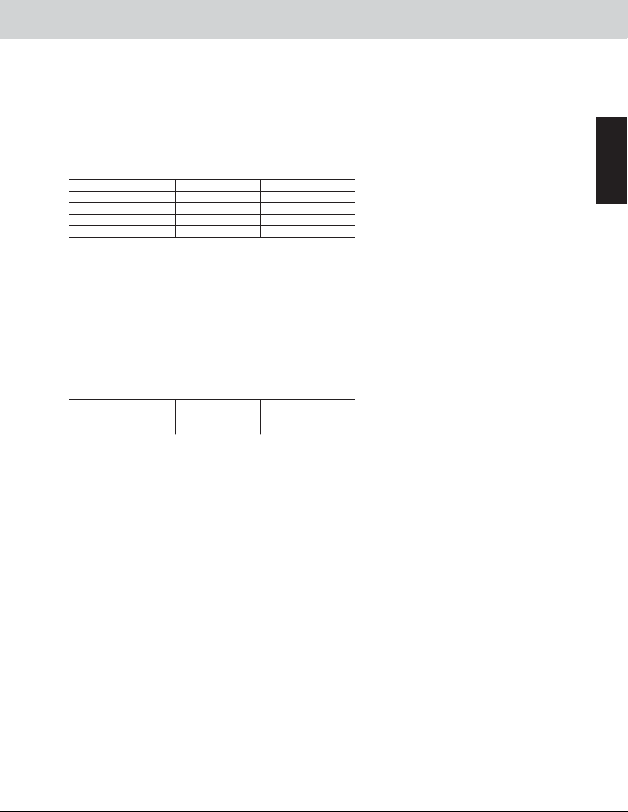
The W-2WAY ECO-i is a system that allows multiple outdoor units to be connected. The outdoor units all contain
inverter compressors, and the system does not utilize the sub units that were used in earlier systems.
The outdoor unit where the unit No. is set to “1” includes the CCU (command controller unit) functions that are
used to control the entire system. As a result, the system will not operate if no outdoor unit has been set as unit
No. “1.”
Required settings for Test Run
Control Functions
1
System address
No. of indoor units
No. of outdoor units
Unit No.
Outdoor unit No.1
At time of shipment At time of shipment
1
1
1
1
On-site setting On-site setting
System 1 ~ 30
1 ~ 40 units
1 ~ 3 units
Unit No. 1
Outdoor unit No. 2
1
1
1
1
Not necessary
Not necessary
Not necessary
Unit No. 2
This system can be expanded to connect a maximum of 3 outdoor units. (The max. system capacity shall be within
24 Ton.)
The CCU functions are disabled at all units except the unit that is set as unit No. 1. Therefore no problems will
result even if the system address, No. of indoor units, and No. of outdoor units settings are made at the other units.
However, making these settings may be convenient for manual backup operation, as it eliminates the necessity of
making the settings again if unit No. 1 fails.
1 - 2
Page 8
W-2WAY ECO-i SYSTEM
2. Selecting an Outdoor Unit for Operation
Control Functions
2-1. Outdoor Unit Operating Rules
Because in this system all outdoor units contain an inverter compressor, ordinarily there is no absolute order of
priority for compressor operation. Therefore there is no order of priority for the outdoor units.
However, it is possible to operate the outdoor units in sequence, beginning with unit No. 1, by using the outdoor
unit maintenance remote controller to change the outdoor unit EEPROM settings.
* For information concerning EEPROM settings, refer to the field application functions.
2-2. Delayed Start of Outdoor Units
(1) Delayed start of outdoor units in the same system
If it is necessary to operate the compressors simultaneously at multiple outdoor units, each outdoor unit will
start, beginning with unit No. 1, after a delay of a number of seconds equivalent to the outdoor unit address.
The units do not start simultaneously.
This is in order to reduce the load on the power receiving equipment.
Outdoor unit Outdoor unit
address 1 address 2
Starts after 1 second Starts after 2 seconds
(2) Delayed start for each system
At the time of factory shipment, delayed start for each system is not set to occur. Therefore when systems are
linked and multiple systems are selected for start simultaneously by the central control device, all systems will
begin operating simultaneously. For this reason, a function is included to delay the start time for each system
address when systems are linked and multiple systems are selected for start by the central control device.
In order to enable this delay time, it must be set in the EEPROM for each system. Those systems where this
setting has been made will start after a delay according to their system addresses.
* For information concerning EEPROM settings, refer to the field application functions.
1
2-3. Outdoor Unit Stop Rules
(1)
Simultaneous stop of multiple outdoor units
When all outdoor units, or multiple outdoor units, must stop, the units stop at the same time. However, depending on the communications timing, a difference of approximately 10 seconds may occur.
(2) Stopping individual outdoor units
The last unit to stop operating is the outdoor unit that contains the inverter compressor with the shortest
amount of operating time.
In cooling mode, all inverter compressors in the outdoor units are designed to operate simultaneously
Therefore, all the outdoor units will stop at a time when any one unit is stopped. In heating mode, the out
door unit which has the inverter compressor with the shortest amount of operating time continues to run and
rest of the other outdoor units may be stopped.
1 - 3
.
-
Page 9
3. Compressor Control
3-1. Compressors Mounted in the Outdoor Units
[CHDX07263, CHDX09663]
Capacity
72 96
W-2WAY ECO-i SYSTEM
Control Functions
1
Installed
compressor
Compressor 1
Compressor 2
INV
Compressor 1
Type 72
Rotary
Scroll
DC Inverter DC Inverter
–––
Constant
speed
Compressor 2
5 hp
hp = horsepower
INV
Compressor 1
Type 96
3-2. Compressor Selection Rules
In cooling mode, all inverter compressors in the outdoor units are designed to operate simultaneously. All the
inverter compressors will stop at a time when the outdoor is stopped accordingly. Constant-speed compressors
run in order of the shortest amount of operating time. In heating mode, the inverter compressor with the shortest
amount of operating time runs at first followed by the compressors in order of the shortest amount of operating
time including inverter units.
* Immediately after installation, all compressors have an operating time of zero. In this case, the compressors
start in the following sequence: Inverter compressor > Constant-speed compressor 1 > Constant-speed compressor 2.
Examples of accumulated operating time: ODU=Outdoor Unit
Suppose the following tentative system.
Comp 1
Comp 2
ODU 1
100 hrs.
150 hrs.
ODU 2
70 hrs.
160 hrs.
Compressor Selection Sequence in Cooling Mode:
All the inverter compressors are firstly selected simultaneously.
Comp 1
Comp 2
ODU 1
1st
3rd
ODU 2
1st
4th
Compressor Selection Sequence in Heating Mode:
First, the inverter compressor with the shortest amount of operating time is selected. And then, the remained
other compressors are selected and start in the order of shortest amount of operating time
Comp 1
Comp 2
ODU 1
3rd
4th 2nd
ODU 2
1st
.
1 - 4
Page 10

W-2WAY ECO-i SYSTEM
3. Compressor Control
Control Functions
3-3. Compressor Capacity Control
The compressor operating conditions vary depending on the indoor unit operating conditions and the effects of
indoor heat load, outdoor temperature and other factors. Unit No. 1 (CCU) calculates the required capacity according to these operating conditions, and allocates the capacity requirement among the outdoor units, according to the
compressor start/stop rules. Fine adjustments to system capacity control are made by the inverter compressors.
(Depending on the conditions, all inverter compressors may be operating for fine adjustment.)
3-4. Inverter Compressor Capacity Control
(1)
The inverter compressor has a center limit value and upper limit value for the operating frequency. These limits
are set for each outdoor unit capacity.
(2) The inverter frequency during operation may be lower than the frequency listed above due to overload current
protection control.
* If Quiet mode is selected, the inverter may stabilize at a frequency lower than those stated above.
For information about Quiet mode, refer to the field application functions.
* If the Power Demand Mode is selected, the inverter may stabilize at a frequency lower than those stated
above. Refer to the Field Application Function for the detail.
3-5. Forced Compressor Stop
Once a compressor stops, it will not start for a period of 3 minutes (3-minute forced OFF). However, this does not
apply when the compressor was forced to stop as the result of a control operation during the special controls (start
control, defrost control, refrigerant oil recovery control, etc.) which are described later.
3-6. Roadmap Control
(1) The below mentioned Roadmap Control are performed according to the pressure sensor on the outdoor unit
and the 2 temperature sensors attached to the indoor unit heat exchanger coil.
* With the roadmap control in heating mode, the pressure detected by the pressure sensor at high pressure
side is converted to the saturation temperature. This converted saturation temperature is called the “High
Pressure Saturated Temperature”.
,
1
(2)
This control is performed every 15 seconds.
(3) The evaporation temperature control and the temperature used to determine the area (A, AB, B, C) for the con-
densation control shown in the figure on the next page, may vary depending on the relationships among factors
including the difference between the room temperature setting and the air intake temperature (=air intake temperature difference) and the difference between the air discharge temperature setting and the air discharge
temperature (=air discharge temperature difference).
(4) Definitions of evaporation temperature and condensation temperature
Evaporation temperature (Te):
Condensation temperature (Tc): Highest temperature among the outdoor unit pressure sensor temperature and
* E3 temperature in heating mode is not used for the condensation temperature detection, because it may indi-
cate the temperature of superheated gas.
Lowest heat exchanger temperature (E1, E3) at any indoor unit
the heat exchanger temperatures (E1) at all indoor units where the heating
thermostat is ON.
Ordinarily, this is the outdoor unit pressure sensor temperature. (If multiple
outdoor units are connected, this is the highest outdoor unit pressure sensor
temperature. )
1 - 5
Page 11
1
W-2WAY ECO-i SYSTEM
3. Compressor Control
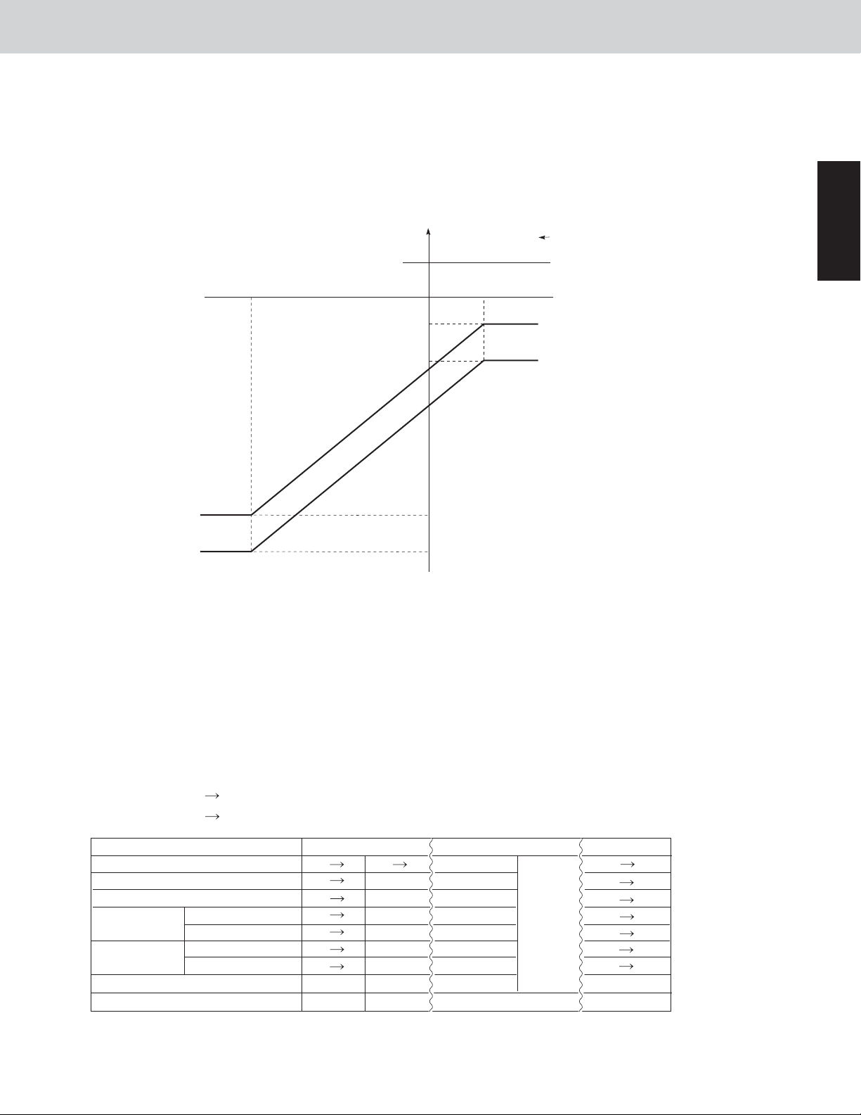
3-6-1. Evaporation Temperature (Te) Control: Control of Indoor Units Operating in Cooling Mode
60.8
°F
Horsepower increase
permitted
51.9
51.8
Horsepower increase
permitted
41.1
41.0
Horsepower increase
prohibited
35.6
Horsepower decrease
35.4
Area A
Area AB
Area B
Area C
53.6
51.8
45.5
0
Maximum requirement level [L]
15
41.0
35.6
30
Control Functions
* Depending on the maximum requirement level of the indoor unit, the judgement
temperatures for each area may vary as shown in the figure.
(1)
For indoor units that are operating in Cooling Mode, if one unit is selected for a test run mode, the room temperature control by the set temperature cannot be performed. Areas B and C are assumed to be area A for control
purposes, instead. By this reason, the compressor continues its operation regardless of the low evaporation
temperature (This is used for additional charging of refrigerant, test run checking etc.) Vapor may be discharged
if the test run continues for a long time. However, this does not indicate problems.
(2) Even within the same area, the compressor capacity varies depending on the refrigerant temperature.
(3)
For 6 minutes after the compressors start, area C is considered to be area B for control purposes.
(4)
During special control, control of the compressor capacity according to Te is not performed.
(5)
If the thermostat turns OFF while Te is within area C, the next time the compressor starts it may restart from a
lower capacity.
(6) When the area changes to area C, area C is considered to be area B for control purposes for the first 6 min-
utes, even if the horsepower is the minimum value within the range where capacity control is possible (operation with inverter frequency of 25 Hz only). Subsequently if C area continues, the thermostat turns OFF.
1 - 6
Page 12
3. Compressor Control
W-2WAY ECO-i SYSTEM
Control Functions
3-6-2.
Condensation Temperature (Tc) Control:
Control of Indoor Units Operating either in Cooling Mode or Heating Mode
PX=125.6
* Depending on the maximum requirement level
of the indoor unit, the judgment temperatures
for each area may vary as shown in the figure
(example).
°F
PX –0.1
118.5
118.4
116.6
116.4
113.0
112.8
Thermostat OFF
Horsepower decrease
Horsepower increase
prohibited
Horsepower increase
permitted
Horsepower increase
permitted
Area D
Area C
Area B
Area AB
Area A
118.4
116.6
109.4
100.4
98.6
0
Maximum requirement level [L]
107.6
3015
(1) For indoor units which are operating in Heating mode, if one unit is selected for a test run, the air intake tem-
perature difference is ignored, however Tc control is performed according to the figure above in order to prevent excessive load. (This is used for test run checks, etc.)
(2) Even within the same area, the compressor capacity varies depending on the refrigerant temperature.
1
(3)
Temperature PX is the coefficient value used to correct for any deviation with the high pressure or condensation temperature. It may vary. (At the time of shipment it is 127°F.)
(4)
If the condensation temperature (Tc) enters area D and the thermostat turns OFF, the next time the compressor
starts it may restart from a lower capacity.
3-6-3. Protection control
Protection control consists of 2 types of protection: discharge temperature protection and current protection. The limit
values from this protection control are incorporated into the output compressor capacity increase/decrease values that
were calculated from control based on the temperature at the indoor unit heat exchanger coil (roadmap control).
In some cases, the control shown below may stop the compressor, issue a warning, or reduce the compressor
*
capacity.
(1)
Discharge Temperature Protection
During operation when only a single outdoor unit is installed, the air discharge temperature level is determined
(the highest value is used), and the compressor capacity is limited, by using the air discharge temperature of
the operating compressor (as shown in the tables below).
Air discharge temperature level: Highest level among the air discharge temperature levels of all compressors
Air discharge temp. level
5
4
3
2
1
0
Discharge temp. °F
221
219
217
212 ~ Less than 217
208 ~ Less than 212
Less than 208
Decrease by 2 horsepower
Decrease by 1 horsepower
Decrease by 0.5 horsepower
Permit horsepower increase (slowly)
No control
Horsepower limit
Prohibit horsepower increase
The values shown in the table above are reduced to the values calculated by roadmap control.
1 - 7
Page 13
W-2WAY ECO-i SYSTEM
3. Compressor Control
(2) Current Protection
Inverter compressor current control is composed of primary current control and secondary current control.
Current protection control for the inverter compressor is performed by self-protection in the inverter circuit, and
does not increase or decrease the compressor capacity.
Control Functions
1
Primary current
-
16.0A~
14.5A~
13.5A~
Secondary current
75.0A or (302°F)
16.5A
13.5A
13.0A
80H
z
90H
z
12.5A
12.0A
Inverter compressors stop (HIC auto. protection)
Inverter compressors stop (When 100ms is detected,
current protection works.)
Hz decrease in the inverter compressor
Prohibit Hz increase in the inverter compressor
Permit Hz increase in the inverter compressor
Control
3-6-4. Roadmap Control after Trip
When restarting after the trip stop occurs, the horsepower may increase slowly depending on the trip counter value.
(1) If trip counter =1, the horsepower increases at a speed that is 1/2 of ordinary roadmap control.
(2) If trip counter =2, the horsepower increases at a speed that is 1/3 of ordinary roadmap control.
The trip counter will be cleared if no trip occurs within 10 minutes after operation starts.
1 - 8
Page 14

W-2WAY ECO-i SYSTEM
4. Special Controls
In addition to ordinary heating and cooling operation, this system also includes the following 3 types of special controls for control of the system as a whole.
1.
4-way Valve Adjustment Control
2.
System refrigerant oil recovery control
3.
Defrost control
Control Functions
4-1. 4-way Valve Adjustment Control
When the microcomputer is initialized immediately after power-ON, after warning output, and all outdoor units are
kept stopped for a preset period (standard = 60 minutes) , the 4-way Valve Adjustment Control will be performed.
This control is intended to changeover the 4-way valve of outdoor unit. When the unit has been stopped for long
period, and if refrigerant has accumulated somewhere in the tubing, recovery of the refrigerant is performed. This
control can also compensate for tubing thermal loss by radiation during heating start as well as for oil recovery.
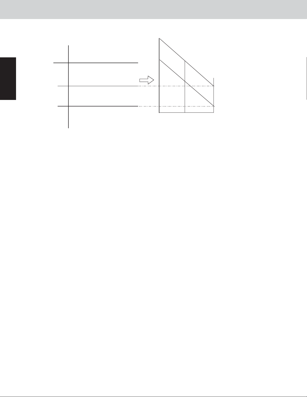
(1) Cooling control when the outdoor unit heat exchanger is acting as a condenser
Control time
Outdoor units
Electronic Thermostat
Indoor
units
*
Expansion Valve
RAP valve kit
Fan
When the above operation is finished, normal operation starts at the horsepower determined by the indoor units where
thermostats are ON.
60 seconds
All outdoor units operate at the maximum horsepower.
Valves at all indoor units operate at a fixed pulse according to the indoor unit capacity.
Valve kits at all indoor units operate in Cooling mode (OFF status).
Fan operates at the set fan speed or stops, depending on the indoor unit operation
mode.
1
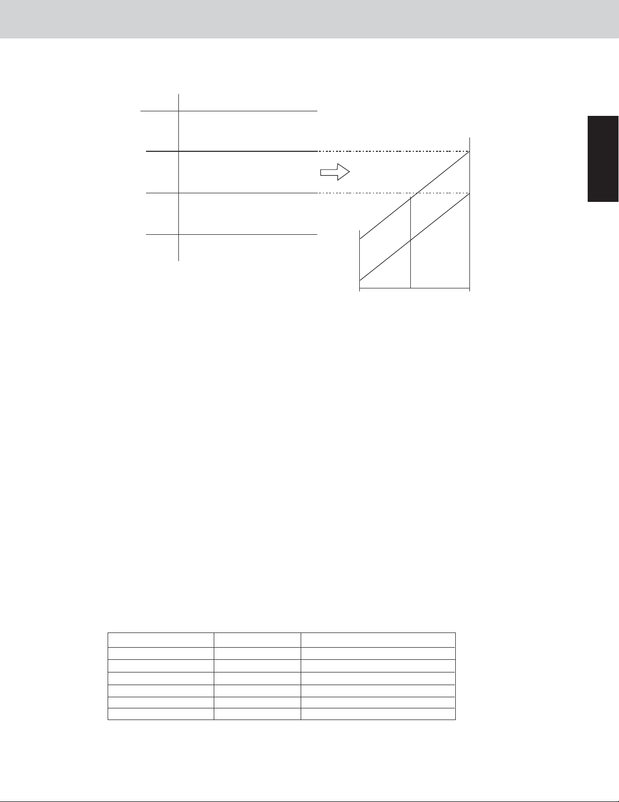
(2) Heating control when outdoor unit heat exchanger is acting as an evaporator
Control time
Outdoor units
Electronic Thermostat
Expansion Valve
Indoor
units
*
When the above operation is finished, normal operation starts at the horsepower determined by the indoor units
where thermostats are ON
RAP valve kit
Fan
Minimum 1 min - Maximum 10 min [until max (pressure sensor temp., E1) 95°F ]
All outdoor units operate at the maximum horsepower.
Valves at all indoor units operate at 250 pulses as a default.
Valve kits at all indoor units operate in heating mode (ON status).
Fan operates at the set fan speed, stops or operates at a very low speed,
depending on the indoor unit operation mode.
.
4-2. System Refrigerant Oil Recovery Control
4-2-1. System refrigerant oil recovery cycle
This control is performed using the cooling cycle during cooling operation and using the heating cycle during heat-
ing operation.
4-2-2. Start of System Refrigerant Oil Recovery Control
When the oil level in an operating compressor is detected as 0 (zero), the compressor stops in 120 seconds. If this
compressor repeats this operation 3 times and the oil level does not reach 2, system refrigerant oil recovery control is started.
When the compressor has stopped because the oil level is 0, a count is added to the alarm counter. The counter
*
for this compressor is not cleared unless the oil level for that compressor reaches 2, or else alarm output occurs.
1 - 9
Page 15
1
W-2WAY ECO-i SYSTEM
4. Special Controls
4-2-3. Refrigerant Oil Recovery Control between Systems
(1)
Simplified flow of system refrigerant oil recovery control
Refrigerant oil recovery control between systems shall be performed as the flow mentioned below.
Normal operation 3-minute stop Refrigerant oil recovery control between systems (Max. 3 minutes) 3-
minute stop Normal operation
(2)
Cooling cycle
Indoor
units
(3)
Heating cycle
Indoor
units
Control time
Outdoor units
Electronic Thermostat
Expansion Valve
RAP valve kit
Fan
Control time
Outdoor units
Electronic Thermostat
Expansion Valve
RAP valve kit
Fan
Maximum 3 minutes (Stops once before and once after control.)
All outdoor units operate at maximum horsepower.
Valves at all indoor units operate at a fixed pulse according to the indoor unit capacity.
Valve kits at all indoor units operate in Cooling mode (OFF status.)
Fan operates at the set fan speed, or stops depending on the operation mode of the
indoor unit.
Maximum 3 minutes (Stops once before and once after control.)
All outdoor units operate at maximum horsepower.
Valves at all indoor units operate at 480 pulse.
Valve kits at all indoor units operate in Heating mode (ON status.)
Fan operates at the set fan speed, stops or operates at a very low speed.
Control Functions
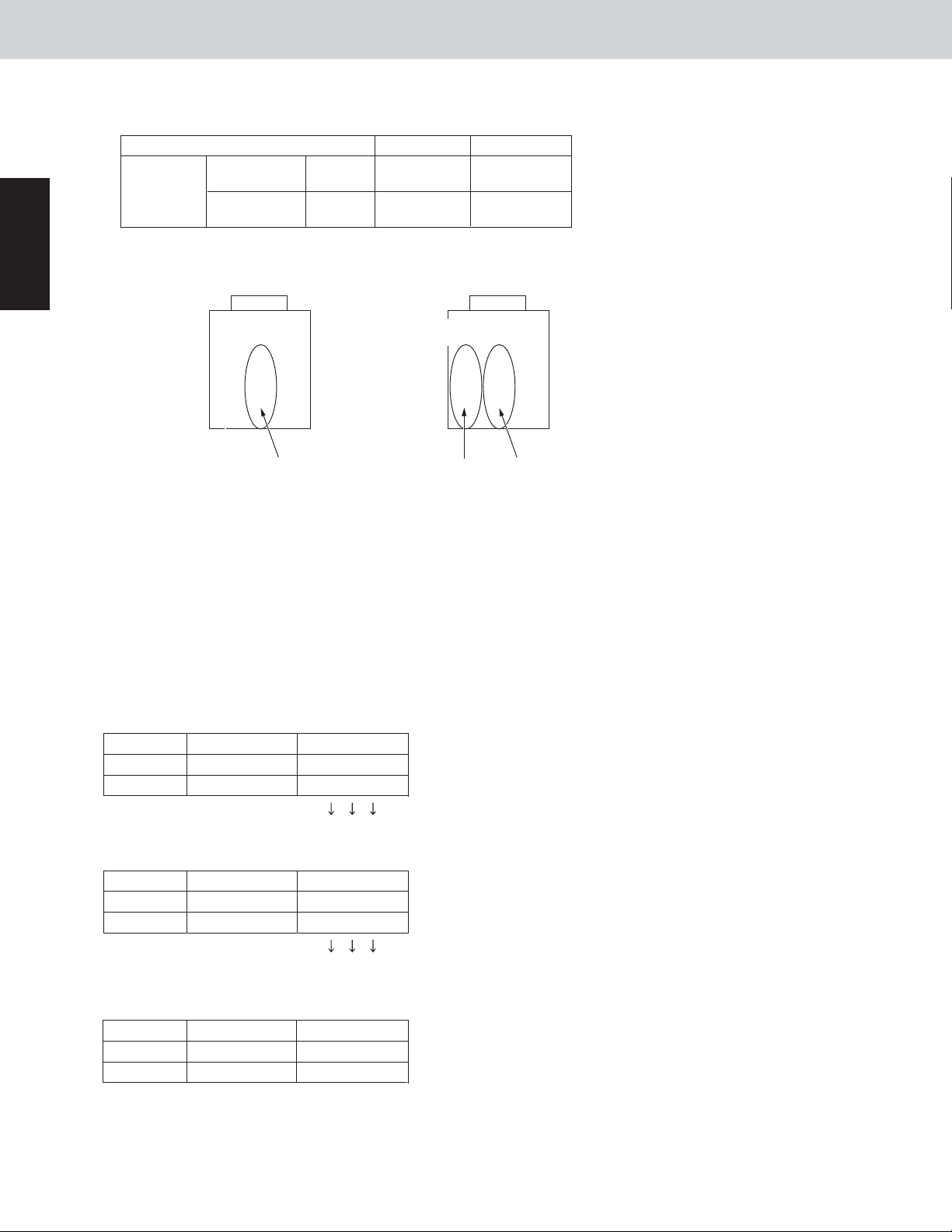
4-3. Defrost Control
4-3-1. Defrost Methods
This system uses the following 2 defrosting systems.
System employs Defrost control method
1 outdoor unit in the refrigerant system
2 outdoor units in the refrigerant system
4-3-2. Constraint conditions
(1)
Frost detection does not occur for 5 minutes after operation starts.
(2)
Defrost does not begin again for 35 minutes of A/C operation after defrost was once completed.
(3)
If all indoor units are stopped while defrost control is in effect, or if the outdoor unit is stopped due to protection
control or another reason, then defrost control will not start for a minimum of 10 minutes after restart occurs.
Reverse cycle defrost
Outdoor unit cycle defrost
1 - 10
Page 16
W-2WAY ECO-i SYSTEM
4. Special Controls
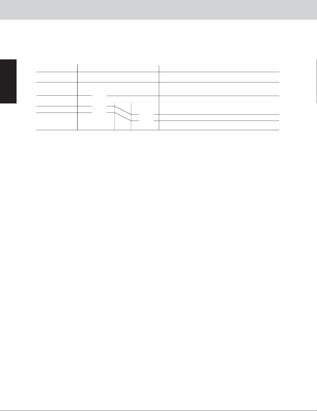
4-3-3. Frost detection
(A) Frost detection does not occur for 5 minutes after operation starts.
(B) Frost is detected when either condition 1 or 2 below is met.
Condition 1: L2 line or below is detected twice, each time continuously for 4 minutes, when the compressor is
operating.
Condition 2: L1 line or below is detected for a total of 60 minutes when the compressor is operating.
Control Functions
Heat exchange liquid temperature °F
–6.5
Defrosting operation
end temperatur
50
30
26
17
14
–9
–13
e
50
The frost detection area is
located under the thick lines
(The end temperature
is different from the
above detection
temperature.)
External temperature °F
L1
L2
4-3-4. Outdoor units where defrost occurs
Even if the total time has not reached 35 minutes, if there is 1 or more outdoor units that fulfills the defrost detection conditions, all operating outdoor units perform defrost control at the same time.
* Defrost control is also performed at outdoor units where the outdoor unit heat exchanger is not functioning as an
evaporator (such as stopped outdoor units).
1
4-3-5. Reverse Cycle Defrost
If there is 1 outdoor unit and no thermal storage tank in a refrigerant system, a reverse cycle defrost will be carried out.
• Defrost flow E: Evaporator operation
C: Condenser operation
E C: Switching from evaporator operation to condenser operation
C E: Switching from condenser operation to evaporator operation
Outdoor unit status
Stopped indoor units
Indoor units where fan is operating
Cooling mode
indoor units
Heating mode
indoor units
Thermostat ON
Thermostat OFF
Thermostat ON
Thermostat OFF
Compressor
Time
Defrost preparation
E C
C E
C E
C E
C E
C E
C E
Stopped Stopped
1 min
E C
E
E
E
E
E
E
Operating
1 min
Defrost in progress
C
E
E
E
E
E
E
Operating
1 - 11
Defrost
end
judgment
Max. 10 min
Defrost end
C E
E C
E C
E C
E C
E C
E C
1 min
Page 17
1
W-2WAY ECO-i SYSTEM
4. Special Controls
4-3-6. Outdoor unit cycle defrost
Outdoor unit cycle defrost is performed in systems where 2 outdoor units are connected to the refrigerant system.
(1)
Description of outdoor unit cycle defrost
With this defrost method, when 1 outdoor unit operates in defrost mode (heat exchanger operating as a con-
denser), another outdoor unit operates as an evaporator in the same way as in ordinary heating mode.
In this way, the other outdoor unit is heating the unit where defrost is occurring. When 1 outdoor unit completes
defrost, the other outdoor unit performs defrost in the same way.
Because the amount of time that the unit operates as an evaporator is very short, there is little danger of frost
forming again quickly. Rather, because the heat source is very powerful, it is possible to shorten the defrost
operating time.
Defrost sequence
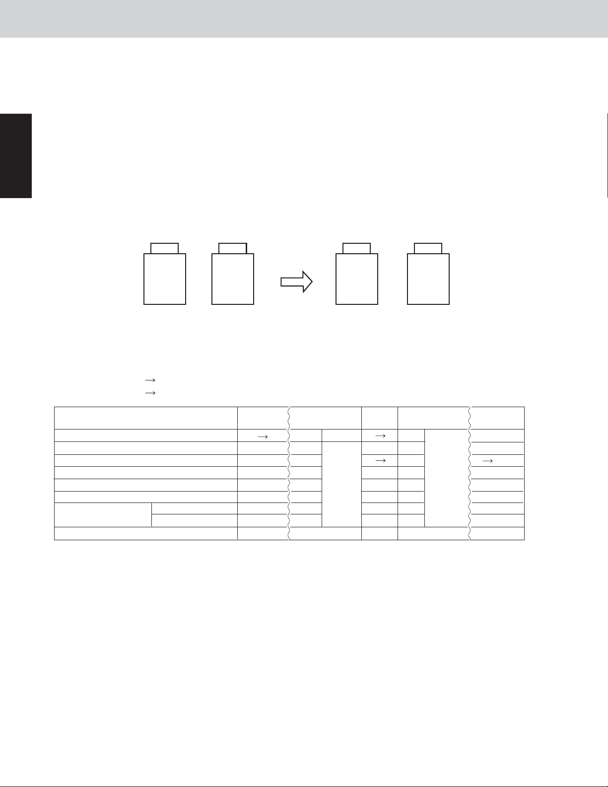
(2)
Outdoor unit cycle defrost is always completed in 2 defrost operations.
(A) When there are 2 outdoor units
Switch
Defrost
outdoor unit outdoor unit
Evaporator
Evaporator
outdoor unit outdoor unit
Defrost
Control Functions
First operation Second operation
• Defrost flow E: Evaporator operation
C: Condenser operation
S: Shut off
E C: Switching from evaporator operation to condenser operation
C E: Switching from condenser operation to evaporator operation
Outdoor unit(s) where defrost occurs first
Outdoor compressor(s) where defrost occurs first
Outdoor unit(s) where defrost follows later
Outdoor compressor(s) where defrost follows later
Stopped indoor unit(s)
Indoor units where fan is operating
Heating mode indoor
units
Thermostat ON
Thermostat OFF
Time
Defrost
preparation
E C
OFF
E
ON
S
S
C
C
1 min
Defrost in
progress
C
ON
E
Defrost
ON ON
end
S
judgment
S
C
C
Switch
C E
OFF
E C
OFF
S
S
C
C
1 min
E
ON
C
SS
S
C
C
Defrost in
progress
Defrost
end
judgment
Defrost
preparation
E or S
OFF
C E or S
OFF
S
C
C
1 minMax. 6 minMax. 6 min
1 - 12
Page 18

W-2WAY ECO-i SYSTEM
4. Special Controls
4-3-7. Defrost end judgment conditions
Defrost ends when either of the below defrost end judgment conditions is met.
Condition 1: The temperatures are 50°F or higher at all temperatures sensors installed on the outdoor unit heat
exchanger coils.
However, if there is any other outdoor unit where the defrost end condition has not been met, defrost
control continues for all outdoor units, and system defrost control is not ended.
Condition 2: The maximum defrost time listed in the table above has elapsed.
4-3-8. System defrost end
When all outdoor units where defrost control is in effect have met the defrost end conditions, defrost control is
ended for the system.
Control Functions
1
1 - 13
Page 19

5. Other Controls
5-1. Oil Control
5-1-1. Oil level
W-2WAY ECO-i SYSTEM
Control Functions
1
Oil level
2
1
0
Meaning Conditions of oil Judgement
Sufficient
Slightly low
Extremely low
The compressor contains oil more than
the oil level which is necessary and
sufficient for normal operation.
The compressor contains sufficient oil
but there is a possibility of shortage
against the required oil level.
The compressor oil is short against
the required oil level sufficient for normal
operation.
There is no problem.
Confirm that oil is returned after
performing the oil control operation.
Confirm that oil level is recovered to the
required level after performing the oil
recovery control between systems.
At the time immediately after the oil level changes from 2 to 1, there is a specified amount of oil in the compressor.
Namely, soon after the oil level is changed to 1, the oil in the compressor is not empty. If the oil level “0” indication
continues for more than 5 to 10 minutes, it seems short of oil in the system. Check for any oil leakage as well as the
refrigerant tubing.
5-1-2. Oil level detection
Excess oil in the compressor is sent by bypass via a capillary tube to the low-pressure circuit. The temperature
detected by a temperature sensor is used to determine whether it is oil (warm) or refrigerant (cold).
5-1-3. Self-separator oil recovery control
* When a low oil level is detected, this control recovers the oil which has accumulated in that oil separator and
sends it to the compressor.
Operation when oil level is not 2.
(1)
30 seconds after the oil level changes from 2 to 1, the recovery valves turn ON.
However, if the oil level becomes 2, this control is stopped.
5-1-4. Unit refrigerant oil recovery control – utilizing balance tubes
* If the low oil level continues, that outdoor unit (oil-receiving outdoor unit) receives a supply of oil from operating
outdoor units where the oil level is not low (oil-supply outdoor units).
(1) Control at the oil-supply outdoor unit begins 3 minutes after the oil level at the outdoor unit dose not become 2.
Oil supply is performed for a maximum of 5 minutes from each unit.
(2) When oil supply is ended, oil supply from that outdoor unit will not occur again for a period of [(No. of outdoor
units minus1) x 5 minutes]. In addition, oil supply is ended if the oil-receiving outdoor unit oil level changes to 2,
or if the oil-supply outdoor unit oil level becomes low.
(3) The supply of oil is received from 1 unit at a time, in sequence, according to the order of priority of their inverter
compressors.
(4) Operation during unit refrigerant oil recovery
(A) Oil-receiving outdoor unit
The recovery valve turns ON and remains ON.
(B) Oil-supply outdoor unit
The balance valve turns ON and remains ON.
The bypass valve repeatedly turns ON and OFF according to a constant cycle.
5-1-5. Indoor unit refrigerant oil self-recovery control
Refer to the items concerned with indoor unit special control.
1 - 14
Page 20
W-2WAY ECO-i SYSTEM
6. Operation of Solenoid Valves
Control Functions
6-1. Refrigerant Control Valve [RCV]
The main purpose of this valve is to detect the flow of refrigerant (refrigerant volume) on the indoor-unit side when
the outdoor unit heat exchanger is functioning as a condenser. When the valve determines that there are signs of
a low refrigerant level, refrigerant is supplied from the receiver tank to the system.
The OFF conditions take priority over the ON conditions for this valve.
(1)
This valve is OFF when the outdoor unit is stopped.
(2)
This valve is ON when special control is in progress.
(3)
(4) Control during normal operation
(A) Cooling operation
This valve turns ON when symptoms of insufficient refrigerant gas occur at an
indoor unit.
This valve turns ON when the outdoor air temperature is 59°F or below. (Under
these conditions the high pressure is low and refrigerant flow becomes poor.)
This valve turns OFF when symptoms of refrigerant overcharge are detected at
the outdoor unit.
(B) Mixed cooling/heating operation
The RCV turns ON at stopped outdoor units when the heat exchanger at another outdoor unit is functioning as a condenser.
Hp
1
6-2. Refrigerant Balance Valve [RBV] – Gas Purge Valve
The main purpose of this valve is to detect the flow of refrigerant (refrigerant volume) on the indoor-unit side when
the outdoor unit heat exchanger is functioning as an evaporator. When the valve determines that there are signs of
excess refrigerant, refrigerant is recovered at the receiver tank.
This valve is ON during heating operation and when the outdoor unit heat exchanger is functioning as an evaporator during mixed heating/cooling operation. It also turns ON in order to recover refrigerant at the outdoor unit after
heating operation is stopped.
* This valve is never turned ON at the same time with the RCV.
(1)
The OFF conditions take priority over the ON conditions for this valve.
(2)
This valve turns ON for 30 – 50 seconds after the outdoor unit stops, and then turns OFF.
(3)
This valve turns ON once after the outdoor unit starts.
(A) Heating operation
This valve is ON during heating operation and when it turns ON for the purpose
of recovering refrigerant in the outdoor unit at the end of the heating operation.
After the valve turns from ON to OFF, it will not turn ON again for 15 minutes.
This valve turns ON when poor refrigerant flow at an indoor unit is detected,
and when symptoms of overcharge are detected, if the heat exchanger at the
outdoor unit is functioning as an evaporator.
(4) This valve turns OFF when an abnormal drop in discharge gas temperature is detected.
(5) This valve turns OFF when a drop in the detected receiver tank temperature contin-
ues for a set length of time, and when liquid back-flow is judged to be occurring.
Lp
1 - 15
Page 21

1
W-2WAY ECO-i SYSTEM
6. Operation of Solenoid Valves
Control Functions
6-3. Recovery Valve (ORVR)
This valve recovers refrigerant oil from the balance tube to the compressor.
(1) When unit is stopped
This valve is always OFF.
(2) When unit is operating
This valve turns ON when separator oil self-recovery control is in progress.
(A)
This valve is ON when unit refrigerant oil recovery control is in progress (oil-receiving unit).
(B)
This valve is ON when control the system in case of insufficient refrigerant gas.
(C)
This valve turns ON for 60 seconds after a constant-speed compressor starts.
(D)
This valve turns ON for 120 seconds after defrost control ends.
(E)
This valve turns ON for 10 seconds after the outdoor unit stops.
(F)
This valve remains OFF at all times other than (A) through (F) above.
(G)
6-4. Bypass Valve (BPV)
This valve flushes the oil from the balance tubes. In addition, it is used for recovering refrigerant from stopped outdoor units during cooling operation.
(1) When unit is stopped
This valve is always OFF.
(2) When unit is operating
This valve is ON at the oil-supply outdoor unit when unit refrigerant oil recovery control is in progress.
* This valve repeatedly turns ON/OFF at regular intervals during unit refrigerant oil recovery control. (It is not
constantly ON.)
1 - 16
Page 22
7. Outdoor Unit Electronic Thermostatic Expansion Valves
[MOV1, MOV2 & MOV4]
W-2WAY ECO-i SYSTEM
Control Functions
7-1. Types of Electronic Thermostatic Expansion Valves
[CHDX07263, CHDX09663]
Electronic
control valve
Capacity
Electronic
control valve 1
Electronic
control valve 2
Electronic
control valve 4
72 96
Heat exchanger
1 valve
Heat exchanger
2 valve
For SC circuit
Heat exchanger
1 valve
Heat exchanger
2 valve
For SC circuit
7-2. Power Initialization
If no indoor units have started (even once) after the power was turned ON, the outdoor unit electronic control valve
operates at 480 pulses.
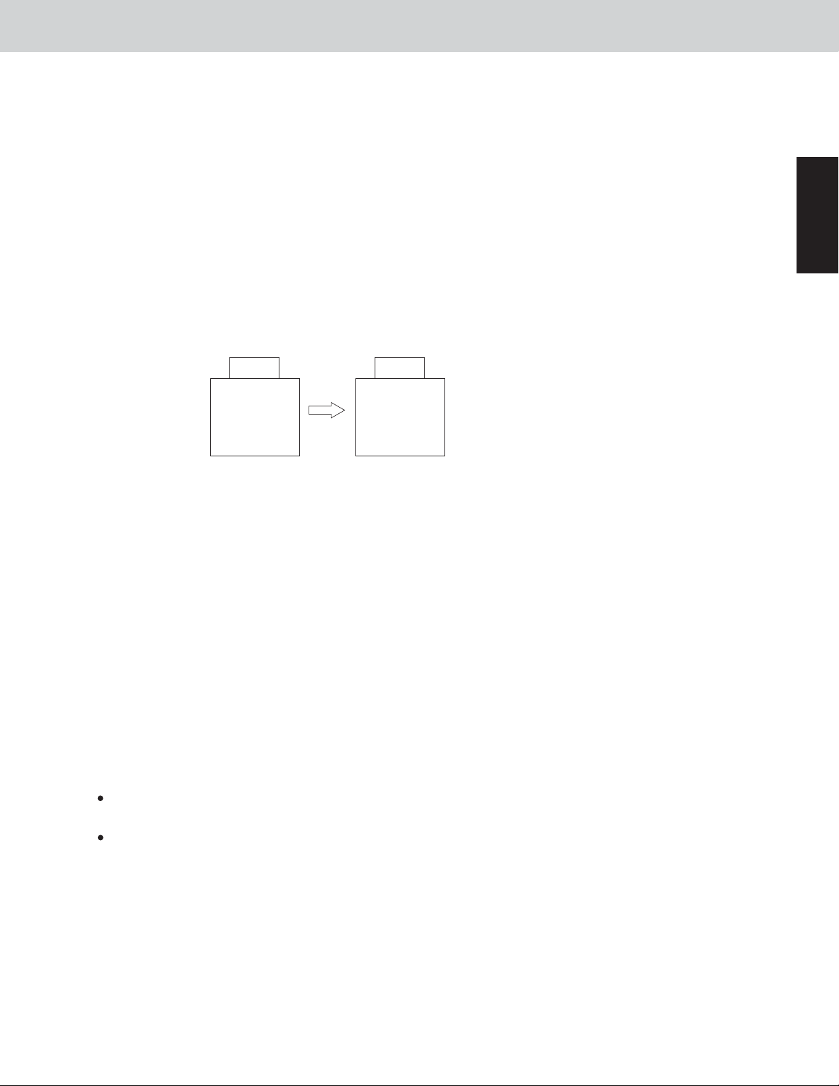
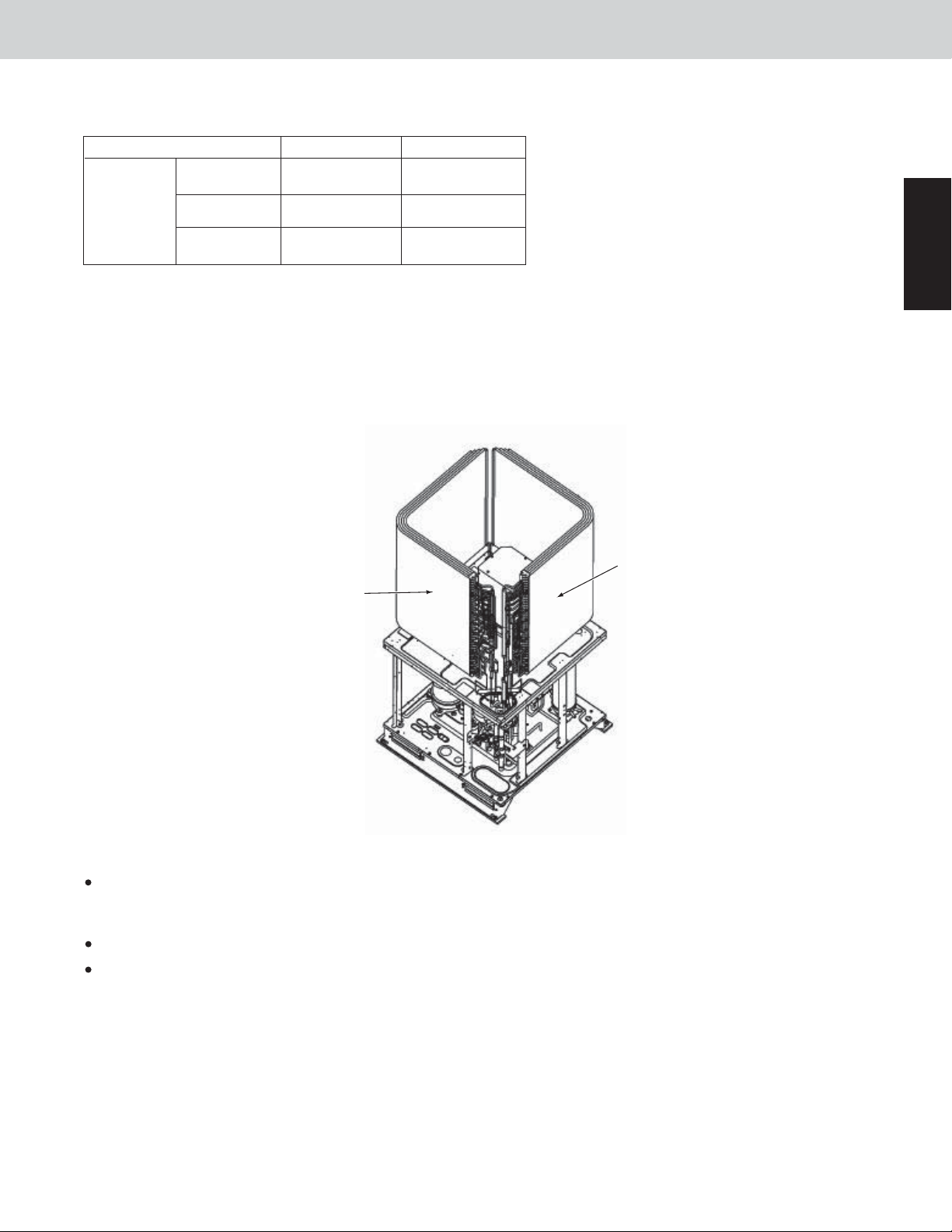
7-3. Heat Exchangers which are controlled by each Electronic Thermostatic Expansion Valve
The configuration of heat exchangers is as shown in the figure below. MOV3 is excluded.
1
Heat
Heat exchanger 2
Front
exchanger 1
Operation of Electronic Thermostatic Expansion Valve during normal unit operation
If any one compressor in the outdoor unit is operating, the outdoor heat exchanger coil is used.
In cooling operation, all the inverter compressors are designed to operate, therefore, all the outdoor heat
exchangers in the outdoor units will be used.
SH control controls the difference between the liquid temperature and gas temperature to 2°F ~ 10°F.
During heating mode SH operation in the heat exchanger 2 side, in order to prevent a liquid-back or high load
operation from occurring a control may be implemented so that refrigerant may not flow intentionally to the heat
exchanger.
1 - 17
Page 23
1
7. Outdoor Unit Electronic Thermostatic Expansion Valves
[MOV1, MOV2 & MOV4]
W-2WAY ECO-i SYSTEM
Control Functions
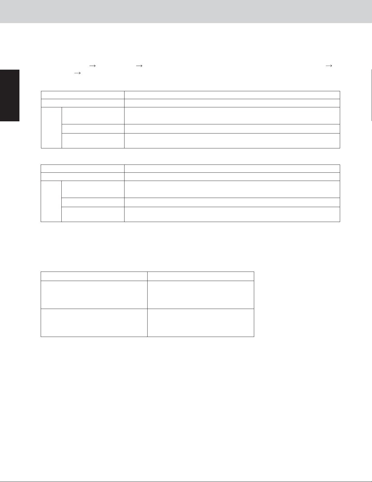
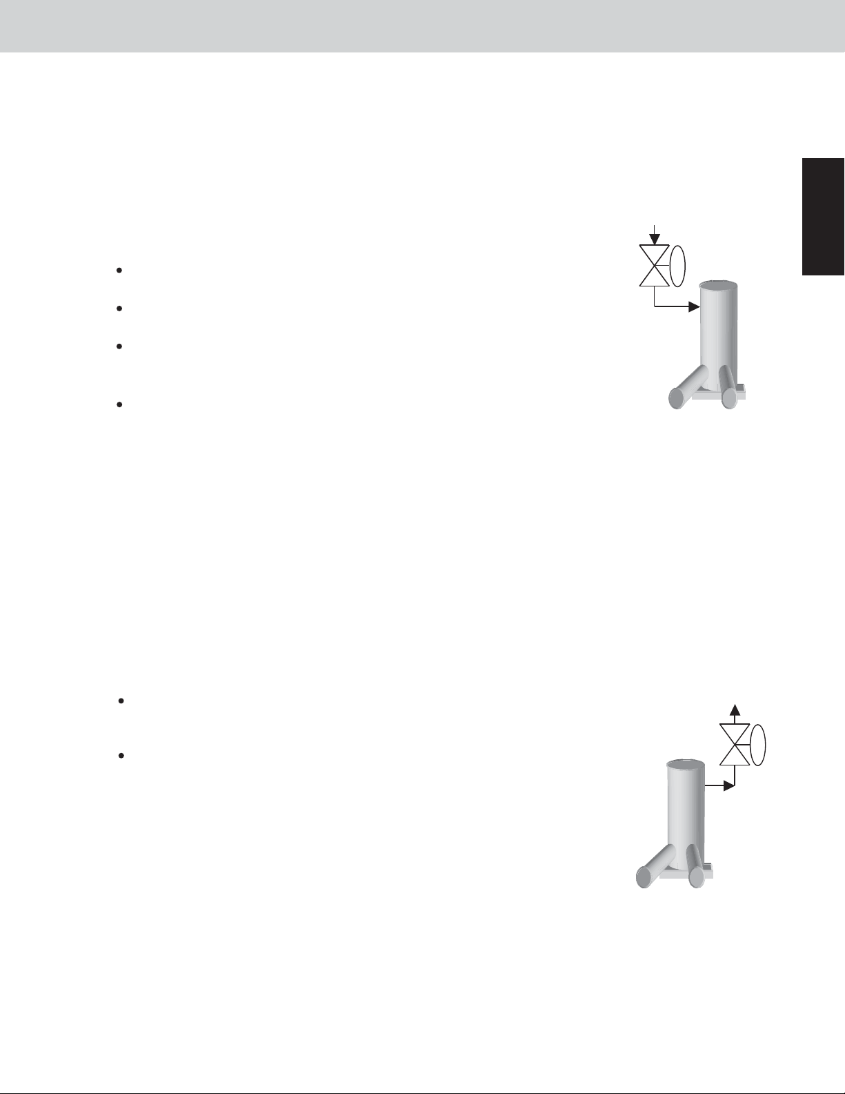
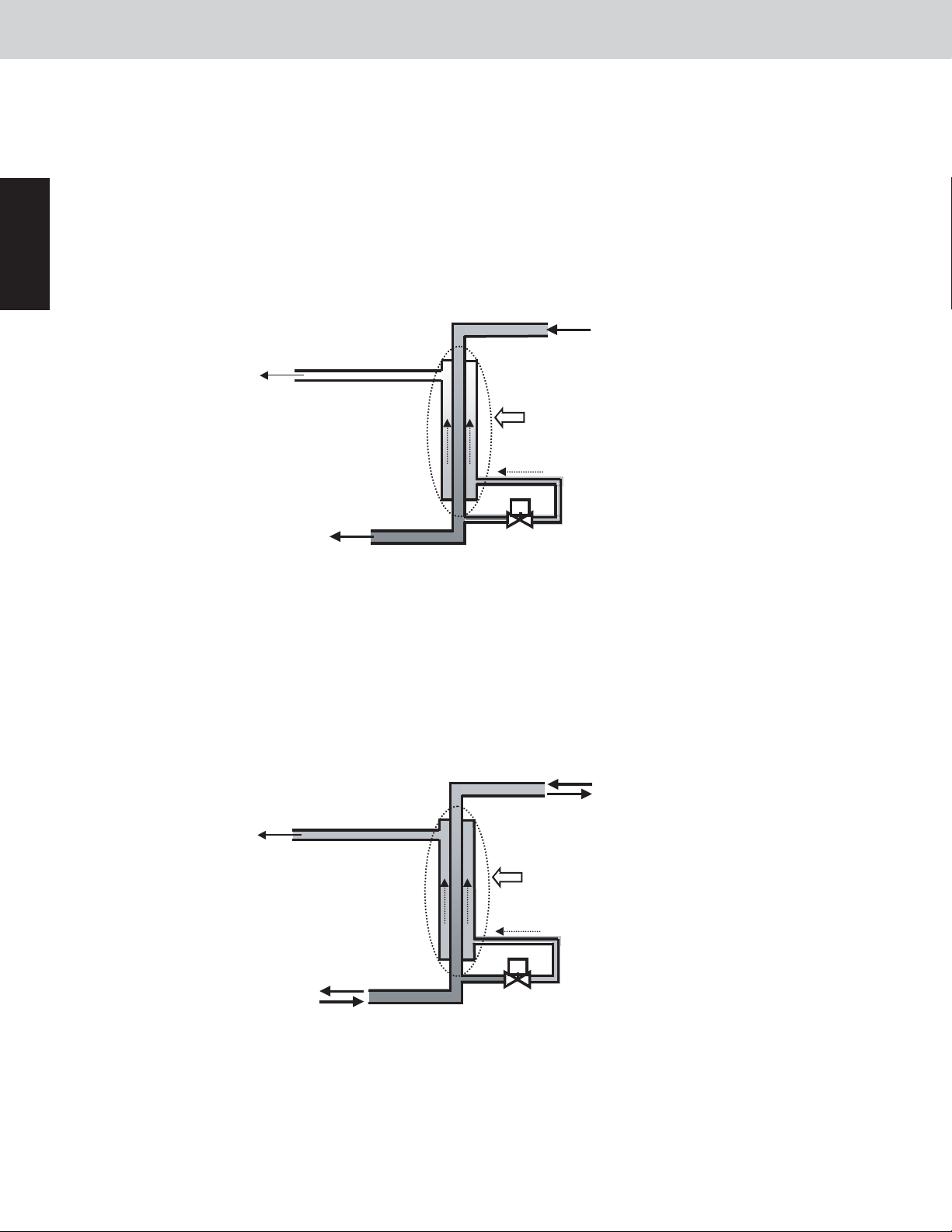
7-4. SC Circuit Electronic Control Valve [MOV4]
(1) SC Control (Cooling Mode only
During cooling operation, the liquid refrigerant which condenses at the outdoor unit heat exchanger flows into
the receiver tank, and SC (sub-cool = supercooling) approaches 0°F. When SC is small and the length of the
tubing connecting the indoor and outdoor units is long, the refrigerant flow in the indoor unit will be reduced significantly. To prevent this trouble from occurring, MOV4 operates so as to increase supercooling in the double
tube coil near the outlet of the outdoor unit.
MOV4 controls refrigerant so that it will not flow back to the compressor in the liquid state with a suction temperature sensor near the accumulator and a low pressure sensor.
Gas refrigerant returns
to the accumulator.
)
Liquid refrigerant (SC = 0°F)
Refrigerant on the outer side evaporates,
cooling the liquid refrigerant on the inner side.
Liquid refrigerant
(large SC)
Electronic control valve 4
(expansion valve) controls the flow.
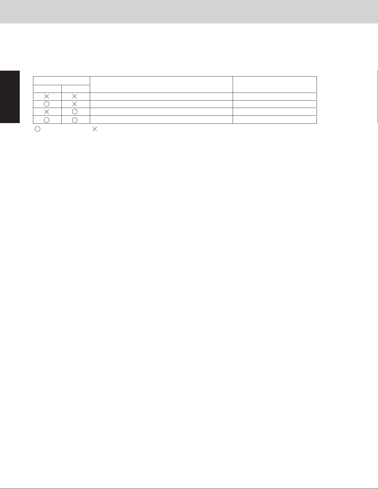
(2) Operation when discharge temperature is high
When the discharge temperature increases, the SC circuit electronic thermostatic expansion valve opens to
480 pulses to cool down the compressor. This operation takes priority over operation intended to increase SC.
It is performed at top priority in all operating modes. In addition, the valve opening adjustment will be made
when the discharge temperature falls.
Liquid refrigerant returns
to the accumulator.
Does not fully evaporate,
resulting in liquid back-up.
Liquid refrigerant
Liquid refrigerant
Electronic control valve
4 opens to 480 pulses.
1 - 18
Page 24

W-2WAY ECO-i SYSTEM
8. Outdoor Fan Control
Control Functions
8-1. Fan mode
These outdoor units utilize a DC fan motor that can be controlled in a maximum of 16 steps (16 modes).
However, fan modes 15 and 16 can only be used if high static-pressure mode has been set.
* For information concerning EEPROM settings, refer to the field application functions.
8-2. Outdoor Fan Min. Fan Mode and Max. Fan Mode
Min. fan mode
Cooling operation
Heating operation
*
Even if the fan mode is 0 during cooling operation, the fan mode may change to 1 at regular intervals for temperature protection of the inverter hybrid IC.
Outdoor air temp. > 59
Outdoor air temp.
1
<
59°F: 0
°F
: 1
Max. fan mode
14
14
8-3. Fixed Initial Fan Mode
For the first 30 seconds after operation starts, the mode is fixed at the initial mode which was calculated from the
relationship between the outdoor air temperature and the outdoor unit horsepower.
If the outdoor unit horsepower changes dramatically, say for about 2 hp, the initial mode may be recalculated and
may be again fixed for 30 seconds.
1
8-4. Operation after Fixed Initial Fan Mode
After the fixed initial fan mode, the fan mode is increased or decreased according to the operating conditions.
(1) When all indoor units are operating in cooling mode
(A) Fan mode is increased when the high pressure satulation temperature sensed by the pressure sensor is
high, and is decreased when the pressure sensor temperature is low.
* The fan mode is always increased when the high pressure satulation temperature sensed by the pressure
sensor is 113°F or higher.
The fan mode may be decreased when symptoms of insufficient refrigerant gas are detected at an indoor unit.
(B)
(2) When all indoor units are operating in heating mode
If the condensation temperature is low, the fan mode is increased at regular intervals.
(A)
If the condensation temperature is high, the fan mode is decreased in order to prevent excessive loads.
(B)
The fan mode may be increased when the outdoor liquid temperature drops to 44°F or below.
(C)
8-5. Snow Removal Control
(1)
When the outdoor air temperature is 50°F or below, the fan operates for 30 seconds every 2 hours in fan mode
8, even when the outdoor unit is stopped or the heat exchanger is not in use. This control is intended to prevent
snow from accumulating on stopped fans. (Because the outdoor air temperature cannot be accurately detected
when the unit is stopped, a higher outdoor air temperature is used for the control condition, in order to ensure
correct operation.)
(2)
If the fan mode becomes 0 during cooling operation, the fan mode is changed to 1.
*
This control is predictive control. Use a snowfall sensor as necessary according to the installation conditions.
8-6. When the Compressor Magnet Switch Seizing Alarm Occurs
Because there is the possibility that the high pressure has increased, the fan operates in Max. fan mode.
8-7. Other
This unit includes settings for high static-pressure and for Quiet mode.
For information about these settings, refer to the field application functions.
1 - 19
Page 25
W-2WAY ECO-i SYSTEM
9. Demand Control
Serial-parallel I/O must be connected in order to perform demand control. The below input is received by serialparallel I/O, and demand control is performed.
The demand values can be set as needed with this device. For more information, refer to the field application functions.
Control Functions
1
Demand setting
Contact 1
Input present
:
Contact 2
Control
No control
Operates to the upper limit for the rated current.
Operates to 70% of the upper limit for the rated current.
Always in stop condition.
Input not present
:
Demand meaning
Operates to maximum capacity.
-
-
-
* The rated current indicates the current value that is listed in the catalog or similar material.
1 - 20
Page 26
W-2WAY ECO-i SYSTEM
10. Indoor Unit Control of the Electronic Control Valve
Control Functions
10-1. Normal Control
(1) Cooling operation
Position of electronic control valve
Outdoor unit operating
Cooling
Stopped
Fan
Thermostat
Thermostat
OFF
ON
Performs SH control in the range of 55 – 480
pulses.
20 20
20 20
20 20
* The SH target value is controlled so that the E3 - E1 becomes between 2°F to 6°F, depending on the operating
conditions.
However, a decline in the required level may cause the SH target value to increase. Be aware that in this case, the
electronic control valve closes slightly. This can be easily identified incorrectly as insufficient gas.
(2) Heating operation
(A) Except Type D
Position of electronic control valve
Outdoor unit operating
Liquid refrigerant is gradually returned to the outdoor unit
at pulses ranging from 55 to 80.
Liquid refrigerant is gradually returned to the outdoor unit
at pulses ranging from 55 to 80.
Liquid refrigerant is gradually returned to the outdoor unit
at pulses ranging from 55 to 80.
Performs SC distribution control within the range of 55–
480 pulses.
Heating
Stopped
Fan
Thermostat
OFF
Thermostat
ON
Outdoor unit
stopped
–
Outdoor unit
stopped
85
85
85
–
1
* The SC target value is controlled so that the high pressure saturated temp. - E1 becomes between 10°F to
40°F , depending on the operating conditions.
(B) Type D
Position of electronic control valve
Outdoor unit
stopped
–
Heating
Outdoor unit operating
Stopped
Fan
Thermostat
OFF
ThermostatONPerforms SC distribution control within the range of 55 –
480 pulses.
20 20
20 20
20 20
* The SC target value is controlled so that the high pressure saturated temp. - E1 becomes between 10°F to
40°F, depending on the operating conditions.
However, if installation is combined with except Type D, the high pressure saturated temp. - E1 may be
controlled between 10°F to 80°F.
1 - 21
Page 27
10. Indoor Unit Control of the Electronic Control Valve
10-2. Special Control
W-2WAY ECO-i SYSTEM
Control Functions
1
Control
4-way valve
adjustment control
Reverse cycle
defrost control
Outdoor cycle
defrost control
System refrigerant
oil recovery control
Operating
mode
Cooling
Heating
Heating
Cooling/
heating
Cooling
Heating
Subject indoor units Position of electronic control valve
All indoor units
All indoor units
Stopped
Fan
Thermostat
ON
Thermostat
Heating
Heating
OFF
Stopped
Fan
Thermostat
ON
Thermostat
OFF
All indoor units
All indoor units
Fixed pulse for cooling, according to indoor unit
capacity
250
Cooling control, according to indoor unit capacity
Cooling control, according to indoor unit capacity
Fixed pulse for heating, according to indoor unit
capacity
Heating control, according to indoor unit capacity
However, position is 20 pulses for Type D.
60 pulses
60 pulses
60 pulses
60 pulses
Fixed pulse for cooling, according to indoor unit
capacity
250
1 - 22
Page 28

W-2WAY ECO-i SYSTEM
11. Rap Valve Kit Control
A gas tube valve kit may be connected to the Type D indoor unit. When the gas tube valve kit is connected,
operations of gas tube valve kit and indoor unit electronic thermostatic expansion valve are as shown in the
table.
Control Functions
Stopped
Thermostat
Thermostat
CoolingHeating
Thermostat
Thermostat
Fan
ON
OFF
ON
OFF
Gas tube valve
OFF
OFF
ON
ON
OFF
OFF
Electronic thermostatic
expansion valve
20 pulses
20 pulses
20 pulses
Superheat control (65 – 480)
20 pulses
Superheat control (50 – 480)
1
1 - 23
Page 29

1
W-2WAY ECO-i SYSTEM
12. Indoor Unit Refrigerant Oil Self Recovery Control
This control is carried out regularly in cooling mode only.
(1)
During stopped, fan or thermostat OFF condition, indoor unit expansion valve is opened regularly for 1 to 2 minutes regularly (at an interval of once every 2 hours.)
(2)
During the thermostat ON, the indoor unit electronic thermostatic expansion valve is opened about 10 pulses
from the current status.
Control Functions
1 - 24
Page 30
W-2WAY ECO-i SYSTEM
13. Discharge Temperature
Control Functions
<Alarm Information>
(1) Discharge temperature protection alarm
This device sets an upper limit discharge temperature of 222°F for all compressors. When the discharge temperature reaches 222°F, that compressor is stopped and restarted. If the same high discharge condition occurs
4 times, then an alarm occurs.
After a compressor has stopped, that compressor will not operate until the temperature has dropped to or
below the start-prohibit temperature.
Discharge temperature protection list
Compressor No. Compressor 1 Compressor 2
Type Inverter Constant-speed
Stop temp.
Start-prohibit temp.
Alarm display
(2) Discharge sensor trouble detection control
An alarm occurs if the discharge temperature remains abnormally high (above 158°F), when the system has
been stopped for 60 minutes.
* In this case, possible causes include sensor failure and compressor overheating caused by an insufficient
level of refrigerant.
The alarm also occurs if the sensor temperature is at or above the abnormal temperature (176°F) when 20 min utes have passed after the compressor stopped.
* In this case, it is possible that the discharge temperature from a different outdoor unit is being detected, due
to an error in the installation of the discharge thermistor.
222°F 222°F
158°F 158°F
P03 P17
1
Discharge sensor failure list
Compressor No. Compressor 1 Compressor 2
Type
Alarm display
Inverter Constant-speed
F04 F05
1 - 25
Page 31

1
W-2WAY ECO-i SYSTEM
14. Current Protection
(1) Fan motor
Alarm Description
P22 Occurs when the fan motor detects over current, or when the motor is locked and
does not turn.
(2) Inverter compressor
Alarm Description
P16
P26
P29
H31
The inverter current includes a primary current and secondary current. The alarm judgment utilizes both currents. Generally, the secondary current is larger that the primary current.
(3) Constant-speed compressor
An alarm occurs when overcurrent or lock current is detected.
List of overcurrent and lock currents
Outdoor unit
Occurs during ordinary operation when overcurrent (27 A) is detected.
Occurs under the same conditions as P16 when the inverter compressor is operating
at or above 80 Hz.
Occurs when missing phase or overcurrent (48 A) is detected at inverter compressor
start. (the alarm at frequencies below 25 Hz)
Occurs when HIC detects overcurrent (75 A), or when an abnormal high temperature
(302°F) is reached.
type
96
Constant-speed
compressor
Compressor 2
Overload
current [A]
23.1
Lock current
[A]
27.3
Control Functions
List of Alarms
Compressor
No.
Detected
current
Alarm display
Compressor 2
Overcurrent
H11 H12
Lock
current
(4) CT circuit detection trouble
Compressor 1 (inverter
compressor)
Compressor 2 (constantspeed compressor)
Alarm
H03
H13
Occurs when an open CT circuit is detected in the inverter
compressor.
Occurs when a current value of 1.5 A or less is detected
when the constant-speed compressor is operating.
Description
If the inverter compressor operating frequency is low, the current value is also low. Therefore this alarm is
detected only when the compressor is stopped.
The operating current of the constant-speed compressors is always higher than 1.5 A. Therefore, this alarm
occurs as the result of an open circuit or failure.
1 - 26
Page 32

W-2WAY ECO-i SYSTEM
15. Pressure Sensor Failure
This system contains 2 types of pressure sensors: a high-pressure sensor and a low-pressure sensor.
(1)
High-pressure sensor failure
Alarms are emitted when the high-pressure sensor becomes an electrical open-circuit or a short-circuit condi-
tions, and a broken wiring, short-circuit or poor connection to the PCB in the high-pressure sensor circuit.
(2)
Low-pressure sensor failure
Alarms are emitted when the low-pressure sensor becomes an electrical open-circuit or a short-circuit condi-
tions, and a broken wiring, short-circuit or poor connection to the PCB in the low-pressure sensor circuit.
High-pressure sensor failure Low-pressure sensor failure
Alarm display
F16 F17
Control Functions
1
1 - 27
Page 33

1
W-2WAY ECO-i SYSTEM
16. Backup Operation
Control Functions
<Field Application Functions>
Backup Operation
16-1. Automatic Backup Operation
This system includes a function for automatic backup operation. An alarm is also displayed to inform the operator
that a failure has occurred.
(1) Alarms that result in automatic backup operation
When compressor trouble or fan motor trouble makes emergency continued operation impossible, automatic
backup operation mode is engaged. Automatic backup mode is not engaged in cases of communications
alarms, automatic reset alarms, and other instances when emergency operation is possible by pressing the
remote controller buttons or changing other conditions.
The alarms that result in automatic backup mode are P16, P22, P26, P29, H11, H12, and H31.
(2) Start of automatic backup operation
If the above alarms occur, the alarm is displayed on the control device. Pressing the control device button again
starts automatic backup mode.
(3) Operation
[1] When 1 outdoor unit is installed
When 1 compressor has failed, backup operation is possible using the other compressors (only in the 09663
model (8 Ton)). However, operation does not occur when the outdoor fan is unable to operate as a result of
alarm P22.
[2] When multiple outdoor units are installed
When automatic backup mode is engaged, the outdoor unit where the above alarm occurred stops operating.
However, if one or more of the compressors is able to operate, then this outdoor unit operates only when the
operation of all outdoor units is required for special control (such as 4-way valve adjustment) or other system
purposes.
(4) Alarm display
If a wired remote controller is present, display blinks during operation.
(5) Canceling automatic backup operation
Repair the outdoor unit where the failure occurred. When repairs are completed, reset the power on outdoor
unit No.1.
<Caution>
After automatic backup mode has been engaged, it will not be canceled automatically when the repair of the
failed outdoor unit is completed. Automatic backup mode will be canceled only when the power on outdoor unit
No.1 is reset. Therefore, after repair work is completed, be sure to check whether or not automatic backup
mode has been canceled.
How to check: [1] Use test run or other means to verify that all outdoor units operate continuously.
[2] If a wired remote controller is present, check that display has disappeared.
16-2. Manual Backup
If an alarm that does not result in automatic backup occurs frequently, possible causes include failure (such as
refrigerant leakage) of a functional part at an outdoor unit other than the unit where the alarm occurs.
In this case, because the outdoor unit service valve must be closed, backup operation must be performed manually.
(1) Backup operation procedure
[1] Disconnecting the failed outdoor unit
(A) Reduce the number of outdoor units set at outdoor unit No.1 by the number of failed outdoor units.
(B) At the S010 switch on the PCB of the failed outdoor unit, turn ON the switch for the compressor to dis
able, and turn ON the “backup” switch.
1 - 28
Page 34

W-2WAY ECO-i SYSTEM
16. Backup Operation
Outdoor unit tonnage 8 Ton
Switches to turn ON
(C) Close all service valves at the failed outdoor units.
(D) Reset the power at outdoor unit No.1.
* When the PCB of the main unit is normal, by implementing the above settings while leaving the communica tion lines between indoor and outdoor units as they are, backup operation of units are possible. In this case,
the outdoor unit that backed up all compressors is not identified as an outdoor unit, however, it can work as
the command controller.
[2] Disabling operation of 1 compressor
At the S010 switch on the PCB of the failed outdoor unit, turn ON the switch for the compressor to disable, and
turn ON the “backup” switch.
<S010 switch>
INV+AC1+BU
INV AC1
( * )
AC2
Backup
ON
Control Functions
1
(A) Compressor 1 backup
(B) Compressor 2 backup
S010
OFF
ON
OFF
ON
OFF
* AC2 switch is not available.
1 - 29
Page 35

W-2WAY ECO-i SYSTEM
17. Service Maintenance Functions
The outdoor unit EEPROM settings can be used for the following functions.
Control Functions
17-1. Outdoor Unit Noise Countermeasure: EEPROM 05 (set at each outdoor unit)
This unit includes 3 types of Quiet modes. (However, when they are engaged, operation is in Quiet mode 24 hours
a day.) Selecting a Quiet mode results in operation that gives priority to reducing noise. Because these modes
involve restrictions on outdoor unit fan modes and the operation frequency, the capacity will be somewhat reduced.
1
Setting
0
112
211
310
Max. fan mode
14
Effect
Normal operation (setting at time of
factory shipment)
Noise reduced by approx. 1 – 2 dB from
the catalog value.
Noise reduced by approx. 2 – 3 dB from
the catalog value.
Noise reduced by approx. 5 dB from the
catalog value.
Amount of capacity reduction
0
Approx. 0.5 hp
Approx. 1.2 hp
Approx. 1.8 hp
* If Quiet mode is set, the capacity will begin to decrease during heating operation at low outdoor temperatures,
when the outdoor air temperature is below standard conditions.
17-2. Anti-slime countermeasures ... EEPROM setting 0C (set only on the main unit)
This setting controls the operation of the drain pump.
Setting
0
1
2
Normal control (setting at time of factory ship ment)
The drain pump operates for 20 minutes at 2-hour intervals.
The drain pump operates for 20 minutes at 20-minute intervals.
Description
3
The drain pump operates constantly.
17-3. Delayed Start for Each System: Outdoor EEPROM 3E (set only on outdoor unit No. 1)
The operation start time can be delayed according to the set system addresses.
This setting reduces the voltage drop by preventing multiple systems from starting at the same time when opera-
tion is restarted after multiple operating systems were stopped due to a power outage or other cause.
Setting
0
1
2
3
No delayed start (setting at time of factory shipment)
Start begins after [1 second x System address]
Start begins after [2 seconds x System address]
Start begins after [3 seconds x System address]
Effect
17-4. Automatic Backup: Outdoor EEPROM 48 (set only on outdoor unit No. 1)
Automatic backup is set to occur at the time the unit is shipped from the factory. However, the automatic backup
function can be disabled by changing this setting to 1.
1 - 30
Page 36

17. Service Maintenance Functions
17-5. Optional Solenoid Valve Control Operation Setting:
Outdoor EEPROM C0 (set at each outdoor unit)
W-2WAY ECO-i SYSTEM
Control Functions
Setting
0
1
2
No output (setting at time of factory shipment)
Refrigerant shut-off valve control
(for cooling when the outdoor air temperature is below standard conditions)
External liquid valve control
(used in special cases when the discharge gas temperature is especially likely to rise)
Operation
17-6. High Static Pressure Mode: Outdoor EEPROM 8F (set at each outdoor unit)
This product can be made compatible with high static pressure by changing the settings.
By changing the setting item 8F to “6,” this product can be made compatible with outdoor unit static pressure of
approximately 0.0085 psi (10 hp type only).
Setting No.
Compatible static
pressure (psi)
Speed
036
0.0014 0.0026 0.0050 0.0074
600 630 670 710 740 770 800
1
2
0.0037 0.0061 0.0085
4
5
17-7. Compressor Operating Sequence: Outdoor EEPROM 46
(set at outdoor units which include CCU functions)
When this setting is set to “1,” the compressors start in sequence beginning from the No. 1 outdoor unit.
(The setting is “0” at the time of shipment. With this setting, compressors with lower operating time are started
first in order to balance the compressor operating times.)
1
17-8. Demand Value Setting: Outdoor EEPROM 1A, 1B
(set at outdoor units that include CCU functions)
Demand setting
Control
Contact 1 Contact 2
No limit
Demand can be set from 40 – 200% at
EEPROM 1A.
Demand can be set from 40 – 200 % at
EEPROM 1B.
Remains stopped.
Demand meaning
Operates to the maximum
capacity.
Current is limited to the set
values.
Current is limited to the set
values.
–
1 - 31
Page 37

W-2WAY ECO-i SYSTEM
18. Other Functions
Control Functions
18-1. Snowfall Sensor Functions: Outdoor EEPROM 04
A unit identified as having a snowfall sensor attached will periodically send a signal indicating the snowfall sensor
input status to all outdoor units in the same system (or all wired outdoor units in the case of linked systems). It is
therefore unnecessary to install and wire multiple snowfall sensors.
(1) Snow fall sensor settings
1
Setting
0
1
2
3
* If the snowfall sensor is used, then depending on the circumstances it is necessary to make the correct setting at
all outdoor units in the system.
* If “control is not performed” is set, control by the above signal is ignored. This setting is used in order to conserve
energy at outdoor units that include a snowfall-protection hood.
Recommended: If a low-speed fan mode is required (for all-year cooling or other reasons), install a snowfall-pro-
(2) Control operation
[1] Outdoor units where “sensor input present” is set send the snowfall sensor input information every 10 min-
utes to all linked systems if the system wiring is linked.
[2] At systems where “control is performed” is set, the above information is used to control operation of the out
door fan.
[3] At systems where “control is not performed” is set, the snowfall sensor input and above information ignored,
and the outdoor fan does not operate.
In case of W-2WAY ECO-i system, control can be performed when snowfall sensor input is connected to
[4]
any outdoor unit.
Sensor input not present. Control is performed. (Setting at time of factory shipment)
Sensor input present. Control is performed.
Sensor input not present. Control is not performed.
Sensor input present. Control is not performed.
tection hood and set this setting to ON
Operation
.
-
<Caution>
Snowfall sensor input information is detected once every 10 minutes. Therefore, the outdoor fan may continue
operating for up to 10 minutes even when there is no snowfall sensor input.
In addition, the outdoor fan may remain stopped for up to 10 minutes when snowfall sensor input is present.
18-2. Function for Automatic Judgment of Insufficient Refrigerant Gas and Overcharg e
This system includes a simple function for judging the level of refrigerant. However, be aware that false judgments
may occur if the control elements of the outdoor unit or indoor unit fail.
(1) Starting refrigerant level judgment mode
Short-circuit the CHECK pin on the No. 1 outdoor for 4 seconds or longer to engage this mode. (The LED on
the outdoor unit PCB begins blinking.)
(2) Conditions for refrigerant level judgment
After judgment mode starts, judgment occurs when all outdoor units in the system have been operating continuously for 30 minutes or longer.
* Refrigerant level judgment requires that all outdoor units operate continuously for 30 minutes or longer. This is
in order to prevent incorrect adjustment of the refrigerant level based on false detection caused by refrigerant
accumulation or recovery at stopped outdoor units, which is due to failures of functional elements.
After the judgment is displayed, repeated judgment will occur under new operating conditions if all outdoor
units continue operating. Therefore, the judgment display may change when later judgments occur.
* Judgment mode is automatically canceled after 4 hours.
1 - 32
Page 38

18. Other Functions
(3) Outdoor unit PCB LED indications in judgment mode
W-2WAY ECO-i SYSTEM
Control Functions
Judgment items
Judgment mode
Normal
Insufficient gas
Overcharge
Judgment not
possible
LED1
Blinking
ON
Blinking
OFF
Blinking alternately
LED2
Blinking
ON
OFF
Blinking
Charge with refrigerant a little at a time.
Recover refrigerant a little at a time.
Recommended response
-
-
-
When judgment mode is not engaged, the LED indicates the normal display (OFF), or else indicates alarms or
other information.
If the insufficient gas or overcharge judgment is not stable, then recover refrigerant a little at a time when the
overcharge display appears. End refrigerant adjustment when the normal or insufficient gas display appears.
(4) Canceling judgment mode
When judgment mode is cancelled, the LED returns to the standard status display (OFF unless an alarm or
other event has occurred).
[1]
Automatic cancel
Judgment mode is canceled automatically when 4 hours have passed after it was started.
[2] Forced cancel
Short-circuit the CHECK pin while the judgment mode display is active in order to cancel judgment mode.
1
<Reference>
General Guidelines for Insufficient Gas and Overcharge
Judgment in automatic judgment mode can be problematic in some cases. Therefore, the following guidelines
are provided for general judgment of the refrigerant amount.
• Symptoms of insufficient gas
Cooling
operation
Heating
operation
There is an indoor unit where the position of the electronic control valve is much higher (open by
300 pulses or more) than it was at start, and the difference [E3 – E1] at that indoor unit is large
(30°F or more).
There is an outdoor unit where the position of the electronic control valve is much higher (open by
300 pulses or more) than it was at start, and the difference [Liquid temp. – Gas temp.] at that
outdoor unit is large (30°F or more).
• Symptoms of overcharge
Cooling
operation
Heating
operation
The high-pressure sensor temperature is 134°F or higher, and the difference [Pressure sensor
temp. – Liquid temp.] at that outdoor unit is large (30°F or more).
There is an indoor unit where the position of the electronic control valve is much higher (open by
300 pulses or more) than it was at start, and the difference [Pressure sensor temp. – E3] at that
indoor unit is large (50°F or more).
These are only guidelines, therefore the judgment may vary depending on the installation conditions, load characteristics, and other elements.
1 - 33
Page 39

– MEMO –
1 - 34
Page 40

W-2WAY ECO-i SYSTEM
Contents
Outdoor Unit Repair Procedures
2. OUTDOOR UNIT REPAIR PROCEDURES
1. Removing Panels ....................................................... 2-2
2. Removing Electrical Component Box and Duct ..............................
3. Discharging Compressor Oil .............................................
4. Backup Operation ......................................................
5. Recovering Refrigerant .................................................
6. Checking for Leakage After Repair .......................................
7. Evacuating System
8. Charging Compressor Oil ..............................................
9. Pumping Out Refrigerant from Outdoor Unit ...............................
10. Compressor .........................................................
11. High and Low Pressure Sensors . . . . . . . . . . . . . . . . . . . . . . . . . . . . . . . . . . . . . . . . .
12. Replacing 4-way Valve .................................................
.................................................... 2-15
2-14
2-16
2-20
2-23
2-35
2-36
2-3
2-5
2-6
2-9
2
2 - 1
Page 41

2
1. Removing Panels
Outdoor Unit Repair Procedures
Procedures:
1. Removing Panels
2. Removing Electrical Component Box and Duct
3. Discharging Compressor Oil
4. Backup Operation
5. Recovering Refrigerant
6. Checking for Leakage After Repair
7. Evacuating System
8. Charging Compressor Oil
9. Pumping Out Refrigerant from Outdoor Unit (when repairing parts other than compressor)
10. Compressor
11. High and Low Pressure Sensors
12. Replacing the 4-way Valve
(1) Front panel removal (Fig. 1)
• Remove the front panel (remove 11 screws).
W-2WAY ECO-i SYSTEM
Front panel
(2) Power outlet panel & valve cover removal (Fig. 2)
• Remove the power outlet panel (remove 2 screws).
• Remove the tubing cover (remove 2 screws).
Fig. 1
Power outlet panel
2 - 2
Tubing cover
Fig. 2
Page 42

W-2WAY ECO-i SYSTEM
2. Removing Electrical Component Box and Duct
Be sure to turn off the power before removing the electrical component box. Then check that the power LED (D53)
on the control PCB of the outdoor unit is not lit.
(1) Remove the electrical component box cover
(remove 6 screws). (Fig. 3)
• When closing the cover after the repair work,
set the upper fringe of the cover should come
to align inside the electrical component box.
(Fig. 3A)
Outdoor Unit Repair Procedures
A
Fig. 3A
(2) Remove power and control wires from terminals.
(3) Remove internal wires with extended connectors
on the outdoor control PCB.
(Solenoid valves, thermistors, crankcase heaters
and others)
(4) Disconnect power lines connected to the sec-
ondary terminals of the magnetic contactor for
the compressor.
(5) Remove the electrical component box (remove 2
screws). (Fig. 4)
CAUTION
Electrical component
box cover
Electrical
component box
2
Fig. 3
Fig. 4
Be sure to release the locking mechanism
before disconnecting each connector.
(6) Remove the center duct. (Fig. 5)
• The center duct is fitted into the upper and lower
ducts, and held in place by the electrical component
box, an arrangement that makes possible independent removal of the center duct.
Upper duct
Center duct
Lower duct
Fig. 5
2 - 3
Page 43

2. Removing Electrical Component Box and Duct
(7) Remove the lower duct: (remove 2 screws, and
a hook)
Lower duct
W-2WAY ECO-i SYSTEM
Outdoor Unit Repair Procedures
2
Fig. 6
(8) Remove the upper duct: (remove 3 screws)
(Fig. 7)
Upper duct
Fig. 7
2 - 4
Page 44

W-2WAY ECO-i SYSTEM
3. Discharging Compressor Oil
Discharged oil can be used for checking the condition of the system. Based on the appearance and color of the
discharged oil, a judgment can be made on whether the system is operating normally or not.
Outdoor Unit Repair Procedures
3-1. Discharging Oil from Oil Separator
Recover the refrigerant from the outdoor unit following the procedure given in “5. Recovering Refrigerant.” Install
hoses as indicated on the equipment and feed nitrogen gas gradually to provide pressure to the system from the
low-pressure outlet and collect oil in a pan or container. (Fig. 8)
The low-pressure outlet port is at the Lo side of the right side.
•
CAUTION
Packless valve or the like
A faulty outdoor unit may remain pressurized. The oil outlet port employs a
•
Schrader-type push-to-release valve. Be careful to avoid accidental oil release
when using the port.
Container
2
Oil outlet port
(For 1/4" (6.35mm)
-dia. connector)
Manifold gauge
Lo Hi
Nitrogen gas
Low-pressure outlet port
Fig. 8
(For 5/16" (7.94mm)-dia. connector)
3-2. Discharging Oil in Compressor
Recover the refrigerant in the outdoor unit following the procedures in “5. Recovering Refrigerant.” Remove the
compressor and discharge the oil in it. Refer to “10. Compressor” for detailed procedures.
3-3. Checking the Oil
Acceptance/rejection criteria for the oil
Condition of
refrigeration cycle
Normal Yellowish None 0.02 or less 3.5 or less
Abnormal overheat-
operation
Motor burnout
Color Odor Total acid value Hue
Brownish
Brownish /
blackish
Condition of oil
Smells somewhat
(not as strong as below)
Pungent / burnt odor
Judgment criteria for changing oil*
0.06 or over 4.0 or over
Changing the oil and system cleaning
with dry-cores are necessary.
Changing the oil and system cleaning
with dry-cores are necessary.
*
It is difficult to measure the total acid value in the field, therefore oil hue and odor are the rule of thumb. Checking
for carbon deposits and abrasive metal powder can additionally be used to assess the system condition.
2 - 5
Page 45

W-2WAY ECO-i SYSTEM
4. Backup Operation
This system includes an emergency automatic backup function that allows the A/C to operate during the period
after trouble occurs until repairs are made. However, during repair and at other times, use manual backup operation.
Outdoor Unit Repair Procedures
4-1. Automatic Backup
For details, refer to the control functions section.
After the alarm details are sent to the control device, control for automatic backup operation begins when the
ON/OFF button of the wired remote controller is pressed again (operation is started after the alarm is cleared).
During this operating mode, “CHECK” flashes on the wired remote controller only to inform the user that operation
is in backup mode. However this is not displayed on any other control devices.
• In order to cancel automatic backup mode, it is necessary to reset the power on the control PCB of the outdoor
unit where the outdoor unit No. setting (S007) on the control PCB is set to No. 1 (main unit).
(It is also available by resetting power of all the outdoor units.)
2
CAUTION
Backup operation is intended as emergency operation until repairs are made. Have repairs made as soon as possible.
If the power is not reset on the control PCB of the No. 1 outdoor unit (main unit),
backup mode operation will continue after the repairs are completed.
4-2. Manual Backup
This backup operation is the conventional method of backup operation. It involves disconnecting the failed outdoor
unit from the system, and operating only the normal outdoor units.
4-2-1. Backup operation by disconnecting the outdoor unit
(1) Changing the outdoor unit control PCB settings
<If the failed outdoor unit is not the No. 1 unit>
• Settings at No. 1 unit (main unit)
Switch on outdoor unit control PCB Action
System address (S003, S002) No change
No. of indoor units (S005, S004) No change
No. of outdoor units (S006) Subtract the number of failed units from the current setting.
Outdoor unit No. (S007) No change
• Settings at normal outdoor units other than the No. 1 unit
No particular changes
• Settings at the failed outdoor unit
No particular changes
However, close all service valves (gas tubes, liquid tube, and balance tube) at the failed outdoor unit, and dis-
connect the wiring between the outdoor units.
2 - 6
Page 46

W-2WAY ECO-i SYSTEM
4. Backup Operation
<If the failed unit is the No. 1 outdoor unit (main unit)>
If the No. 1 unit (main unit) has failed, a different outdoor unit must be set as the No. 1 unit (main unit).
• Settings at the failed No. 1 outdoor unit
– No particular changes
– However, close all service valves (gas tube, liquid tube, balance tube) at the failed outdoor unit, and dis connect the wiring between the outdoor units.
• Settings at No. 1 unit (main unit)
Switch on outdoor unit control PCB Action
System address (S003, S002) Make the same settings as on the failed No. 1 unit.
No. of indoor units (S005, S004) Make the same settings as on the failed No. 1 unit.
Outdoor Unit Repair Procedures
No. of outdoor units (S006) Subtract the number of failed units from the current setting.
Setting outdoor unit No. (S007) Change to “1.”
To this outdoor unit, connect the inter-unit communication line which was previously connected to the
No. 1 unit (main unit).
After recovery work is completed, wire the communication lines between
CAUTION
• Settings at other outdoor units
No particular changes.
(2) Adjusting the refrigerant for backup operation
During backup operation, all of the service valves on the failed unit are closed. However, if a check of the
backup operating conditions shows that the level of gas is low, recover the refrigerant from the failed outdoor
unit. If the level of gas is too high, collect refrigerant at the failed outdoor unit.
Recovering refrigerant
With the normal outdoor units operating, monitor the operating condition and open/close the gas tube service valve on the failed outdoor unit where all the service valves were closed. In this way, recover refrigerant from the failed outdoor unit in order to adjust the amount of refrigerant in the system.
After adjusting the amount of refrigerant, close the gas tube valve at the failed outdoor unit.
indoor and outdoor units again. If it not finished yet, an alarm is emitted
immediately.
2
Collecting refrigerant in the failed outdoor unit
• Short-circuit the vacuum application pin (CN102) on the control PCB of the failed outdoor unit where the
service valves are closed, then turn the power ON. Also disconnect the wiring between the outdoor units.
• With the normal outdoor units operating, monitor the operating condition and open/close the liquid tube service valve on the failed outdoor unit where all the service valves were closed. In this way, collect refrigerant
in the failed outdoor unit in order to adjust the amount of refrigerant in the system.
• After adjusting the amount of refrigerant, turn OFF the power at the failed outdoor unit, release the shortcircuit at the vacuum application pin, and close the liquid tube valve at the failed outdoor unit.
* Refrigerant recovery is not affected by the power status of the failed outdoor unit. However, collecting
refrigerant in the failed outdoor unit is affected by whether the power at that outdoor unit can be turned ON.
If the power cannot be turned ON, use a refrigerant recovery device and recover the refrigerant into a
recovery cylinder in order to adjust the amount of refrigerant in the system.
2 - 7
Page 47

4. Backup Operation
4-2-2. Backup operation by setting the failed compressor not to operate
Backup operation settings for each compressor
INV compressor AC1 compressor Setting for backup operation
OK Failed
DIP switch S010:
Turn BACK UP and AC1 ON.
W-2WAY ECO-i SYSTEM
Outdoor Unit Repair Procedures
2
Failed OK
Failed Failed
DIP switch S010:
Turn BACK UP and INV ON.
DIP switch S010:
Turn BACK UP, INV, and AC1 ON.
2 - 8
Page 48

W-2WAY ECO-i SYSTEM
5. Recovering Refrigerant
Outdoor Unit Repair Procedures
The following equipment and tools are required:
Jumper wire with clips, adjustable wrench, set of manifold gauge valves specially designed for refrigerant R410A
only, vacuum pump, refrigerant recovery unit, pre-purged refrigerant cylinder for recovery, flathead screwdriver, and
outdoor unit maintenance remote controller.
5-1. Refrigerant Recovery Procedures (from outdoor unit)
(1) Turn off the power of the outdoor unit beforehand (at power mains).
(2) Fully close each service valve on the liquid tube, gas tubes, and the balance tube of the outdoor unit.
(3) Connect the outdoor unit’s high-pressure and low-pressure outlet ports with the Hi and Lo sides of the manifold
gauge valves using hoses. (Fig. 9)
The remaining refrigerant in the faulty outdoor unit may create internal pressure.
CAUTION
(4) Connect the manifold gauge valves, refrigerant recovery unit, and recovery cylinder using hoses. To avoid the
entry of air into the refrigerant tubing, carry out this connection work carefully. (Fig. 9)
CAUTION
Before connecting hoses, be sure to confirm that each of the manifold gauge
valves is tightly closed. Note that the connection ports employ Schrader-type
push-to-release valves.
For detailed procedures such as connecting the refrigerant recovery unit with the
recovery cylinder and methods used for recovery, follow the specific instructions
that came with the refrigerant recovery unit.
2
(5) Locate the AP (Air Purge) pins on the control PCB in the faulty outdoor unit and short them using the clips of
the jumper wire. Then restore electrical power to the outdoor unit.
By short-circuiting the AP pins, each solenoid valve in the outdoor unit is forcibly
CAUTION
opened as soon as power comes on, which releases all remaining refrigerant into
the recovery cylinder. Since neglecting this procedure may leave some refrigerant
in the system, it is important that you carry out this step.
(6) Carry out refrigerant recovery.
CAUTION
To determine the completion of refrigerant recovery, follow the instructions that
came with the refrigerant recovery unit.
Refrigerant
recovery unit
Manifold
gauge
Lo Hi
High-pressure outlet
port (For 5/16" (7.94mm)
-dia. connector)
Refrigerant recovery cylinder
Low-pressure outlet port
(For 5/16" (7.94mm)-dia. connector)
Fig. 9
2 - 9
Page 49

W-2WAY ECO-i SYSTEM
5. Recovering Refrigerant
Outdoor Unit Repair Procedures
5-2. Refrigerant Recovery Procedures (Indoor Unit)
The flowchart below shows the refrigerant recovery procedures you must follow when replacing or repairing the
indoor unit due to trouble in the refrigerant circuit.
START
5-2-1. Cooling operation (for all units)
2
Ball valve is provided in the indoor unit
YES
5-2-2. Refrigerant recovery
procedures (1)
Turn off all equipment in system
When replacing or repairing a faulty
unit, let other normal indoor units run
(excluding indoor unit where refrigerant
is recovered)
YES
Power can independently be turned off
for indoor unit where refrigerant is
recovered
YES
Change controllable number of indoor
units (including changes in group
control and integrated-control settings)
Other indoor units can operate normally
Replace or repair faulty unit
Check for leakage in repaired unit H
Evacuate air from repaired unit H
Charge refrigerant in repaired unit H
(Amount of charge should equal that
recovered by refrigerant recovery unit)
Change controllable number of indoor
units (including changes in group
control and integrated-control settings)
NO
NO
NO
5-2-3. Refrigerant recovery
procedures (2)
Fig.8
Modify power to permit turning off
power to refrigerant-recovered
indoor units independently
Turn off all equipment in system
Replace or repair faulty unit
Check for leakage in repaired unit
Evacuate air from repaired unit
Charge refrigerant in repaired unit
(Amount of charge should equal that
recovered by refrigerant recovery unit)
Ready for operation
END
Replace or repair faulty unit
Check for leakage in repaired unit H
Evacuate air in repaired unit H
Charge refrigerant in repaired unit H
(Amount of charge should equal that
recovered by refrigerant recovery unit)
Open ball valve
Ready for normal operation
END
Service work performed on indoor units is done simultaneously using the service ports at the liquid (narrow tube) side
and the gas (wide tube) side ball valves. Refer to each section in the “Installation Instructions” on refrigerant charging,
leak checking, and evacuation procedures.
Open the ball valve
Ready for normal operation
5-2-1. Cooling operation (for all units)
(1) If the remote controller (RCS-TM80BG) is used for maintenance of the outdoor unit
1
Connect the outdoor unit maintenance remote controller to the RC connector (CN006) (3P) (BLU) on any
one of the outdoor unit control PCBs. Then start a test run of all units. (Press and hold the (CHECK)
button for 4 seconds or longer.)
2
Press the (MODE) button and change to cooling operation and ensure that the cooling is performed.
Refer to the test run service manual for the detail of the outdoor maintenance remote controller operation.
It may be possible to determine whether operation is cooling or heating by touching the gas tubing.
Cooling : low temperature (68 °F or lower)
Heating : high temperature (140 °F or higher)
CAUTION
The gas tubing becomes hot (140 °F or higher) in heating mode. Be careful so as
not to be burnt when touching the tubing.
2 - 10
END
Page 50

W-2WAY ECO-i SYSTEM
5. Recovering Refrigerant
(2) If the remote controller (RCS-TM80BG) is not available for maintenance of the outdoor unit
1
Determine the outdoor unit where the unit No. setting (S007) (3P DIP switch) (Blue) on the outdoor unit
control PCB is set to No. 1.
2
Short-circuit the test-run pin (CN023) on the PCB to start test run operation.
3
Leave the unit running for a while, and touch the gas tubing with fingers to determine whether the unit is
running in cooling or heating mode.
If it is in heating, follow the step and later procedures.
Cooling : low temperature (68 °F or lower)
Heating : high temperature (140 °F or higher)
4
Outdoor Unit Repair Procedures
CAUTION
The gas tubing becomes hot (140 °F or higher) in heating mode. Be careful so as
not to be burnt when touching the tubing.
4
Release the short-circuit at the test-run pin (CN023) on the outdoor unit control PCB of the No. 1 unit. Then
short-circuit the stop pin (CN104) to stop operation.
5
Short-circuit the mode-change pin (CN101) on the outdoor unit control PCB of the No. 1 unit.
*
Switching of the 4-way valve occurs immediately before operation starts. Therefore it does not change at
this time. (Mode change cannot be judged from the sound.)
6
Short-circuit the test-run pin (CN023) on the PCB to start test run operation. Leave the unit running for a
while, and touch the gas tubing with fingers to determine that the unit is running in cooling mode.
5-2-2. Refrigerant recovery procedures (1) (using indoor unit ball valve)
(1) If a ball valve with a service port has been provided in the indoor unit as shown in Fig. 10, follow the instructions
given in (2) through (6) below. If the service port is instead located in the outdoor side, follow the instructions in
“5-2-3. Refrigerant recovery procedures (2).”
(2) After running the unit in Cooling mode for about 5 minutes as described in “5-2-1. Cooling operation (for all
units),” fully close the liquid tube ball valve.
(3) Run the unit in Cooling mode for 10 to 20 minutes more.
(4) Fully close the gas tube ball valve, and stop the operation of all units.
(5) Use hoses to connect the manifold gauge valves, refrigerant recovery unit, and refrigerant recovery cylinder
with each other. (Fig. 10)Do each connection quickly to prevent air from entering the tubing.
CAUTION
Remaining refrigerant may create internal pressure, therefore care should be
taken when connecting the hoses.
2
(6) Recover the remaining refrigerant from the indoor unit using the refrigerant recovery unit.
NOTE
To determine completion of refrigerant
Manifold
gauge
Lo
Hi
recovery, follow the instructions that
came with the refrigerant recovery unit.
Refrigerant
recovery
Refrigerant recovery cylinder
Ball valve (separately purchased)
Gas tube
Outdoor
unit
side
Liquid tube
Service port
unit
Fig. 10
2 - 11
Indoor unit
Page 51

2
W-2WAY ECO-i SYSTEM
5. Recovering Refrigerant
Outdoor Unit Repair Procedures
5-2-3. Refrigerant recovery procedures (2): Indoor unit with no ball valve equipped
Refrigerant in all indoor units and the refrigerant tubing circuit must be pumped into the outdoor unit. The maximum
refrigerant storage capacity per a single outdoor unit is approx. 529 oz. Thus, in order to collect all refrigerant from
the system, a separate refrigerant recovery unit is necessary. Follow these procedures to correctly perform pump
down.
Perform work correctly, according to the work procedures given below.
1
Connect the manifold gauge to the high- and low-pressure outlet ports on the outdoor unit where pump down
will be performed. Be sure that no air enters the tubing at this time.
2
Follow the instructions in “5-2-1. Cooling operation (for all units)” and operate all units in Cooling mode for
approximately 5 minutes. Then fully close the liquid tube valve on the outdoor unit where pump down will be
performed.
3
When the high-pressure gauge reaches 406.1 psi or higher, or the low-pressure gauge reaches 72.5 psi or
below, at the outdoor unit where pump down is being performed, press the ON/OFF button on the outdoor unit
maintenance remote controller to stop operation at all units. Then immediately fully close the suction tube valve
on the outdoor unit where pump down is being performed.
* If the outdoor unit maintenance remote controller is unavailable, follow the procedure below to stop all of the
units.
Pull out the SCT connector (2P) (YEL) (CN231) on the outdoor unit control PCB of the unit where pump down
is being performed. When the SCT connector is pulled out, immediately alarm F12 (sensor trouble) occurs
and all outdoor units stop operating. Be sure that you do NOT grasp the lead wire when pulling out the connector. Removing any other connector may not cause the units to stop. Therefore be sure to pull out the SCT
connector only.
CAUTION
It is not necessary to recover the refrigerant from the balance tube. Therefore do
not operate the balance tube valve.
4
Turn off power to all equipment in the system. Then pull out the RC1 connector (4P) (BLU) (CN106) on the outdoor control PCB in the outdoor unit for which pump down has been completed.
* By pulling out the RC1 connector, communication between the main and the sub outdoor units will be isolated.
5
Change the setting of controllable outdoor unit numbers (reduce by 1 unit).
* If the setting is incorrect, the E30 alarm (outdoor unit serial communication signal error) occurs and the unit
will not operate.
6
Turn on power for all equipment in the system and let the remaining outdoor units run in Cooling mode.
7
Repeat steps and and complete pump down for all outdoor units.
8
Using hoses with Schrader-type push-to-release valves, connect the manifold gauge valves to the suction line
1
2
service port, the discharge line service port and the liquid line service port in the next outdoor unit to undergo
pump down. (Fig. 11)
Remaining refrigerant in the system may cause internal pressure. Check that each
CAUTION
valve on the manifold gauge is tightly closed. A Schrader-type push-to-release
valve is provided for each connection port.
9
Use hoses to connect the manifold gauge valves, refrigerant recovery unit, and refrigerant recovery cylinder.
Quickly connect each part to prevent air from entering the tubing.
10
Recover remaining refrigerant from the inter-unit tubing and indoor units using the refrigerant recovery unit.
NOTE
To determine the completion of refrigerant recovery, follow the instructions that came with the refrigerant recovery
unit.
2 - 12
Page 52

5. Recovering Refrigerant
W-2WAY ECO-i SYSTEM
Outdoor Unit Repair Procedures
Refrigerant
recover unit
Refrigerant
recovery cylinder
Manifold
gauge
Lo
Hi
Liquid tube service port
(For 5/16" (7.94mm)-dia.
connector)
Gas tube service port
(For 5/16" (7.94mm)-dia. connector)
Fig. 11
5-3. Recovery of Refrigerant from Entire System
(1) Turn off power to the entire outdoor system.
(2) Short-circuit the AP (Air Purge) pins (CN102) on the outdoor control PCB of all outdoor units, then supply power
to the outdoor units.
* By short-circuiting the AP pins and supplying power to the outdoor units, the solenoid valve in each unit is
forcibly opened and all remaining refrigerant can be recovered.
(3) If any unit has encountered a power failure, follow the instructions in “5-1. Refrigerant Recovery Procedures
(from Outdoor Units)” and perform refrigerant recovery for the faulty outdoor unit.
2
(4) Connect the manifold gauge to the high- and low-pressure outlet ports (Schrader-type valves) on any outdoor
unit. (Fig. 11)
Remaining refrigerant may cause internal pressure. Check that each valve on the
CAUTION
manifold gauge valves is tightly closed. The connection port uses a Schrader-type
push-to-release valve.
(5) Connect the manifold gauge valves, refrigerant recovery unit, and refrigerant recovery cylinder. Quickly connect
each part to prevent air from entering the tubing.
(6) Check that each service valve of the gas tubes, liquid tube, and the balance tube for the outdoor unit has opened,
then perform refrigerant recovery.
* If only a single outdoor unit is installed, the balance tube is not used. Therefore, leave this valve closed.
NOTE
To determine the completion of refrigerant recovery, follow the instructions that came with the refrigerant recovery
unit.
2 - 13
Page 53

2
W-2WAY ECO-i SYSTEM
6. Checking for Leakage After Repair
Outdoor Unit Repair Procedures
6-1. Pressure Check for Leakage of Outdoor Unit
After completing repair of the outdoor unit, carry out the following leakage check.
(1) Check that all service valves for gas tubes, liquid tube, and balance tube in the repaired outdoor unit (units
necessary to carry out the pressurized leak check) are fully closed.
(2) Connect the manifold gauge valves to the high- and low-pressure outlet ports of the outdoor unit.
(3) Feed nitrogen gas into the circuit until 72.5 psi pressure is reached. If it is apparent that the nitrogen gas is not
entering the repaired section, interrupt the feeding. Short-circuit the AP pins (CN102) on the outdoor unit control
PCB, turn on power to run the outdoor unit, then resume feeding nitrogen.
(4) Apply soapy water to the repaired part (such as a newly brazed part), and briefly inspect for any leakage. If there
are any leaks, bubbles will show on the tubing surface.
* To continue the air-tight check after the brief leak inspection, turn on power while short-circuiting the AP pins.
Again feed nitrogen gas to obtain a system pressure of 72.5 psi. Then measure both the outdoor ambient
temperature and the pressure in the system. Leave the system in this state for 1 full day and night, and again
measure the outdoor ambient temperature and pressure (to determine any reduced values). During the
inspection, it is recommended that an awning or cover be used to shield the unit in case of rain. If no problem
is found, purge all nitrogen from the system.
Manifold
gauge
Lo Hi
Nitrogen gas
High-pressure outlet port
(For 5/16" (7.94mm)-dia.
connector)
Low-pressure outlet port
(For 5/16" (7.94mm)-dia. connector)
Fig. 12
6-2. Checking for Leakage in Refrigerant Tubing Between Indoor and Outdoor Units
Refer to the “Installation Instructions” that came with the outdoor unit.
2 - 14
Page 54

W-2WAY ECO-i SYSTEM
7. Evacuating System
This procedure is carried out to ensure there is no remaining refrigerant or other gases (nitrogen, etc.) in the
repaired outdoor unit and tubing.
Outdoor Unit Repair Procedures
7-1. Evacuating Repaired Outdoor Unit
(1) Check that each service valve of the gas tubes, liquid tube, and balance tube in the outdoor unit are fully closed.
(2) Connect the manifold gauge valves to the high-pressure and low-pressure sensor outlets of the outdoor unit.
(Fig. 13)
(3) Connect the manifold gauge valves to the vacuum pump.
* If the AP pins (CN102) on the outdoor control PCB have already been short-circuited, step (4) is not neces-
sary.
(4) Turn off power to the repaired outdoor unit and short-circuit the AP (Air Purge) pins on the outdoor control PCB.
By short-circuiting the AP pins and turning on power to the outdoor unit, all elec-
CAUTION
(5) Turn the power ON at the outdoor unit where vacuum will be applied. Then run the vacuum pump and continue
evacuation until the vacuum condition falls to less than –14.7 psig (5 Torr).
tronic valves in the outdoor unit are forcibly opened and any remaining nitrogen
gas can be recovered. Failure to perform this procedure may result in nitrogen gas
remaining in the refrigerant circuit and causing operating problems. Therefore,
never skip this step.
2
CAUTION
Vacuum pump
To ensure proper evacuation, refer to the operating instructions that came with the
vacuum pump.
Manifold
gauge
Lo Hi
High-pressure outlet port
(For 5/16" (7.94mm)-dia.
connector)
Low-pressure outlet port
(For 5/16" (7.94mm)-dia. connector)
Fig. 13
7-2. Evacuating Refrigerant Tubing Between Indoor and Outdoor Units
Refer to the “Installation Instructions” that came with the outdoor unit.
2 - 15
Page 55

W-2WAY ECO-i SYSTEM
8. Charging Compressor Oil
Outdoor Unit Repair Procedures
8-1. If Refrigerant Has Already Been Charged to Outdoor Unit
Be sure to use an exclusive oil-charging tank for charging compressor oil. Prior to charging, carry out vacuum drying
inside the tank and take care that no air (in the form of bubbles) is permitted to enter the tank.
The oil charging procedures are given below.
* The receiver tank used for maintenance may be used as an exclusive oil-charging tank.
2
When installing the oil-charging
(DPR : 623-081-7937)
tank to the refrigerant system to
serve as a safety bypass circuit for
refrigerant, connect it to the gas
tube service port carefully to
Nipple
avoid releasing refrigerant into the
atmosphere.
CAUTION
Perform oil charging
work carefully so that no
liquid refrigerant enters
Packless valve
(Receiver-tank:
638-015-2988)
the charging tank.
Fig. 14
(1) Evacuation drying in oil-charging tank
With the lower side valve fully closed, open the upper side valve and connect it to the vacuum pump via the
manifold gauge valves as shown below. Run the vacuum pump and evacuate the tank until the pressure falls to
below –14.7 psig (5 Torr) for the evacuation drying. After the evacuation drying is finished, fully close the upper
valve. Next, fully close the manifold gauge valves and stop the vacuum pump.
CAUTION
Vacuum pump
To ensure proper evacuation, refer to the operating instructions that came with the
vacuum pump.
Open Close
Manifold
Lo
gauge
Hi
Upper side
valve
Close
Lower side
valve
Fig. 15
2 - 16
Page 56

W-2WAY ECO-i SYSTEM
8. Charging Compressor Oil
(2) Charging compressor oil into oil-charging tank
Connect a piece of pipe to the lower valve and then insert the other end deeply into the bottom of the oil container. Make sure you avoid letting any air be sucked into the tube. Next, run the vacuum pump and open the
manifold gauge valves, then open the upper and lower valves to begin charging oil into the charging tank.
Manifold
gauge
Upper valve
Outdoor Unit Repair Procedures
Close Open
Close Open
Vacuum pump
Lower valve
Oil
Fig. 16
When the predetermined amount of oil has been charged into the oil-charging tank, immediately close the lower
valve. Next, run the vacuum pump until the system pressure reaches lower than -14.7 psig (5 Torr).
Close the upper valve and then, stop the vacuum pump.
CAUTION
Do this operation quickly because compressor oil easily absorbs moisture from
the air.
(3) Charging compressor oil into outdoor unit
Connect the lower valve to the low-pressure outlet (with Schrader-type push-to-release valve) in the outdoor
unit to be oil-charged, and then connect the high-pressure outlet (with push-to-release valve) to the upper valve
via the manifold gauge valves (at Hi-pressure gauge side). In addition, connect the gas tube service port (with
push-to-release valve) to the DPR (Discharge Pressure Regulator). Carry out the connection work quickly to
avoid letting air enter.
• The hoses may be subject to internal pressure from the refrigerant inside the out
CAUTION
door unit. A Schrader-type push-to-release valve is provided at each connection
port.
• Since the DPR valve opens at pressures of 362.6 psi and above, be sure to connect the DPR to the gas tube service port (low-pressure side).
2
High-pressure
outlet port
(For 5/16"
(7.94mm)dia. connector)
Low-pressure
outlet port
(For 5/16"
(7.94mm)dia. connector)
Gas tube
service port
(For 5/16"
(7.94mm)dia. connector)
Manifold
gauge
Lo Hi
Fig. 17
2 - 17
Lower valve
DPR
Upper valve
Close
Close
Page 57

2
W-2WAY ECO-i SYSTEM
8. Charging Compressor Oil
Next follow the instructions in “5-2-1. Cooling operation (for all units)” at the outdoor unit where oil will be charged,
and start cooling operation at all units. When the operating conditions have stabilized, perform steps 1, 2, and 3 in
sequence and open the valves. When this is done, the refrigerant pressure from operation forces the oil out of the
oil charge tank, and oil is charged into the outdoor unit from the low-pressure outlet port. From time to time close
the upper valve on the top of the oil charge tank (only this valve) and shake the tank to check the amount of
remaining oil.
Low-pressure
High-pressure
outlet port
(For 5/16"
(7.94mm)dia. connector)
outlet port
(For 5/16"
(7.94mm)dia. connector)
Gas tube
service port
(For 5/16"
(7.94mm)dia. connector)
Manifold
gauge
Lo Hi
Procedure 1: Open
Outdoor Unit Repair Procedures
DPR
Upper valve
Procedure 2: Open
Lower valve
Connect from here to
refrigerant recovery unit
Procedure 3: Open
Fig. 18
To terminate the oil charging work, do as follows:
To end the charge process, first close the valve on the high-pressure side of the manifold gauge. Then wait several
tens of seconds after the pressure display on the manifold gauge low-pressure gauge stabilizes (in order to equalize
the pressure with the low-pressure outlet port and to vaporize the refrigerant in the charge tank). Then perform steps
1 and 3 in sequence and fully close the valves. Finally, connect the refrigerant recovery unit to the Lo-gauge side,
shut down all indoor and outdoor units, and then recover the remaining refrigerant in the oil-charging tank, manifold
gauge valves, and connecting hoses. Perform these procedures quickly and securely so that no air can enter.
After, charge the necessary amount of new refrigerant by referring to the “Installation Instructions” that came with the
outdoor unit.
NOTE
To determine the completion of refrigerant recovery, follow the instructions that came with the refrigerant recovery
unit.
8-2. If Outdoor Unit Has Not Been Charged with Refrigerant
When a compressor has been replaced or in any other case where the outdoor unit has not been charged with
refrigerant, first charge with refrigerant then follow the instructions in “8-1. If Refrigerant Has Already Been
Charged to Outdoor Unit” and charge with oil.
Or, alternatively, follow the procedure below.
(1) Connect a tube to the oil outlet port on the outdoor unit to be charged with oil. Insert the other end of the tube
into the oil container.
(2) Follow the instructions in “7. Evacuating System,” and apply vacuum to the outdoor unit to be charged with oil.
When this is done, oil is charged into the outdoor unit through the oil outlet port.
(3) When the unit has been charged with the designated amount of oil, stop the vacuum pump.
CAUTION
The oil absorbs moisture readily. This work must be completed quickly.
2 - 18
Page 58

8. Charging Compressor Oil
W-2WAY ECO-i SYSTEM
Outdoor Unit Repair Procedures
Oil tube outlet port
Low-pressure outlet port
(For 5/16" (7.94mm)-dia. connector)
Oil
Vacuum pump
Manifold
gauge
(For 1/4" (6.35mm)-dia. connector)
High-pressure
outlet port (For 5/16"
(7.94mm)-dia.
connector)
HiLo
Fig. 19
8-3. Charging Additional Compressor Oil (after replacing compressor)
The rated amount of oil is pre-charged in the compressors as given below:
Model name Compressor model Q'ty Pre-charged amount of oil (liters)
CHDX07263 C-9RVN273H0S
(Inverter-controlled rotary compressor)
1 1.9
2
CHDX09663 C-9RVN273H0S
(Inverter-controlled rotary compressor)
JT160G-KTTJ
(Constant-speed scroll compressor)
1 1.9
1 2.1
When replacing a faulty compressor, be sure to first measure the amount of remaining oil in the compressor.
Charge additional new oil equal to the difference in the remaining oil and the rated amount as listed above.
For example: Type of replaced compressor: JT160G-KTTJ
Remaining oil in the removed compressor: 0.58 gal
Additional oil to be charged:
0.58 gal (remaining oil in the removed compressor) – 0.55 gal (rated oil amount) = 0.026 gal
* If the result is a negative amount (remaining oil in the removed compressor is less than the rated amount), it is
not necessary to discharge the extra oil from the system.
For the method used for additional oil charging after compressor replacement, refer to “8-1. If Refrigerant Has
Already Been Charged to Outdoor Unit.”
2 - 19
Page 59

9. Pumping Out Refrigerant from Outdoor Unit
W-2WAY ECO-i SYSTEM
Outdoor Unit Repair Procedures
2
Required equipment and tools:
This work is performed in order to collect the refrigerant from an outdoor unit where repairs (other than compressor
replacement) will be performed into other outdoor units and indoor units, and the refrigerant tubing.
Jumper wire with clips, adjustable wrench, set of manifold gauge valves for the
refrigerant R410A, refrigerant recovery unit, pre-purged refrigerant cylinder for
recovery, flat-head screwdriver, and outdoor unit maintenance remote controller.
9-1. If Remote Controller (RCS-TM80BG) is Used for Maintenance of Outdoor Unit
(1) Refer to “4. Backup Operation” and perform backup operation.
(2) Connect the manifold gauge valves at the Lo side to the low-pressure outlet port of the outdoor unit to be
repaired. Also connect the refrigerant recovery cylinder to any one of the normal outdoor units at the liquid line
service port (Schrader-type push-to-release valve). Perform the connection work quickly so that no air is
allowed to enter. (Fig. 20)
* Connecting the refrigerant recovery cylinder is done to prevent pressure from rising excessively during backup
operation by recovering the refrigerant from the outdoor unit to be repaired.
(Measure the weight of the refrigerant and cylinder itself beforehand and provide sufficient safety measures,
such as installing a high-pressure cutout in the circuit.)
CAUTION
(3) Connect the outdoor unit maintenance remote controller to the RC connector (CN006) (3P) (BLU) on the out-
door unit control PCB of the outdoor unit to be repaired. Then start a test run of all units. (Press and hold the
(CHECK) button for 4 seconds or longer.)
The hoses may be subject to internal pressure from the refrigerant inside the outdoor unit. Check that the manifold gauge valves are fully closed beforehand.
A Schrader-type push-to-release valve is provided at each connection port.
(4) Use the outdoor unit maintenance remote controller to check the operating status of the indoor units. Check
that all units are operating in Heating mode. For details concerning operation of the outdoor unit maintenance
remote controller, refer to the “Outdoor unit maintenance remote controller” item. It is also possible to check the
operating conditions either in cooling or heating mode by touching the gas tube.
Cooling mode : low temperature (68 F or lower)
Heating mode : high temperature (140 F or higher)
CAUTION
(5) Close the suction tube and balance tube on the outdoor unit to be repaired. Then slowly close the liquid tube
service valve.
(6) When the low pressure at the outdoor unit to be repaired reaches 72.5 psi or below, press the ON/OFF button
on the outdoor unit maintenance remote controller to stop all the units. Then immediately fully close the gas
tube valve on that outdoor unit.
CAUTION
(7) Connect the high-pressure gauge side of the manifold gauge to the high-pressure outlet port on the outdoor unit
to be repaired, and connect the manifold gauge to the refrigerant recovery device. Be sure that no air enters the
tubing at this time.
The gas tubing becomes hot (140 F or higher) in heating. Be careful so as not to be
burnt when touching the tubing.
While closing the valves, the rise in discharge temperature or another factor may
cause a protective device to activate, stopping the operation of the outdoor unit.
If this occurs, immediately fully close the gas tube valve on the outdoor unit to be
repaired.
2 - 20
Page 60

W-2WAY ECO-i SYSTEM
9. Pumping Out Refrigerant from Outdoor Unit
(8) Short-circuit the vacuum application pin on the outdoor unit control PCB of the unit to be repaired. Then turn ON
the outdoor unit power.
When the vacuum application pin is short-circuited and the power is turned ON, all
CAUTION
Open both Hi- and Lo-side valves on the manifold gauge valves, and recover the refrigerant remaining in
the outdoor unit. After that, measure the amount of recovered refrigerant.
NOTE
To determine the completion of refrigerant recovery, follow the instructions that came with the refrigerant recovery
unit.
solenoid valves in the outdoor unit are forced open, allowing the refrigerant to be
recovered from all tubes which are separated by solenoid valves. If this work is not
performed, it will not be possible to recover all of the refrigerant at the refrigerant
recovery device. Be sure to perform this step.
Outdoor Unit Repair Procedures
9-2. If Remote Controller is Not Available for maintenance of Outdoor Unit
(1) Refer to “4. Backup Operation” and perform backup operation.
(2)
Connect the manifold gauge valves at the Lo side to the low-pressure outlet port of the outdoor unit to be
repaired. Also connect the refrigerant recovery cylinder to any one of the normal outdoor units at the liquid line
service port (Schrader-type push-to-release valve). Perform the connection work quickly so that no air is
allowed to enter. (Fig. 20)
* Connecting the refrigerant recovery cylinder is done to prevent pressure from rising excessively during the
backup operation by recovering the refrigerant from the outdoor unit to be repaired.
(Measure the weight of the refrigerant and cylinder itself beforehand and provide sufficient safety measures,
such as installing a high-pressure cutout in the circuit.)
2
CAUTION
(3) Determine the outdoor unit where the unit No. setting (S007)(3P DIP switch)(BLU) on the outdoor unit control
PCB is set to No.1.
(4) Short-circuit the test-run pin (CN023) to start operation.
(5) Leave the unit running for a while, and then touch the gas tubing with fingers to determine whether the unit is
running in cooling or heating mode. If it is in heating, follow the step (6) and later procedures.
Cooling : low temperature (68 F or lower)
Heating : high temperature (140 F or higher)
CAUTION
(6) When the unit is operating in heating mode, release the short-circuit at the test-run pin on the outdoor unit con-
trol PCB of the No. 1 unit. Then short-circuit the stop pin (CN104) to stop operation.
(7)
Short-circuit the mode-change pin (CN101) on the outdoor unit control PCB of the No. 1 unit.
Switching of the 4-way valve occurs immediately before operation starts. Therefore it does not change at this
*
time. (Mode change cannot be judged from the sound.)
(8) Short-circuit the test-run pin (CN023) to start operation, leave the unit running for a while. Touch the gas tubing
with fingers to determine whether the unit is running in cooling.
The hoses may be subject to internal pressure from the refrigerant inside the outdoor unit. Check that the manifold gauge valves are fully closed beforehand.
A Schrader-type push-to-release valve is provided at each connection port.
The gas tubing becomes hot (140 F or higher) in heating mode. Be careful so as
not to be burnt when touching the tubing.
2 - 21
Page 61

W-2WAY ECO-i SYSTEM
9. Pumping Out Refrigerant from Outdoor Unit
(9) Close the gas tube and balance tube on the outdoor unit to be repaired. Then slowly close the liquid tube ser-
vice valve.
* When the low pressure at the outdoor unit to be repaired reaches 72.5 psi or below, pull out the SCT connec-
tor (2P) (YEL) (CN231) from the outdoor unit control PCB of that outdoor unit. Then immediately fully close
the gas tube valve on that outdoor unit.
* Pulling out the SCT connector immediately stops all of the outdoor units.
While closing the valves, the rise in discharge temperature or another factor may
CAUTION
(10) Connect the high-pressure gauge side of the manifold gauge to the high-pressure outlet port on the outdoor
unit to be repaired, and connect the manifold gauge to the refrigerant recovery device. Be sure that no air
enters the tubing at this time.
cause a protective device to activate, stopping the operation of the outdoor unit.
If this occurs, immediately fully close the gas tube valve on the outdoor unit to be
repaired.
Outdoor Unit Repair Procedures
2
(11) Open both Hi- and Lo-side valves on the manifold gauge valves, and recover the refrigerant remaining in the
outdoor unit. After that, measure the amount of recovered refrigerant.
NOTE
To determine the completion of refrigerant recovery, follow the instructions that came with the
refrigerant recovery unit.
Faulty outdoor unit
High-pressure outlet port
(For 5/16" (7.94mm)-dia.
connector)
Manifold
gauge
Low-pressure outlet port
(For 5/16" (7.94mm)-dia.
connector)
Other outdoor unit
Liquid tube service port
(For 5/16" (7.94mm)-dia.
connector)
Refrigerant
recovery
cylinder
Connect from here to
refrigerant recovery unit
Measuring scale
Fig. 20
2 - 22
Page 62

W-2WAY ECO-i SYSTEM
10. Compressor
Outdoor Unit Repair Procedures
10-1. Compressor Trouble Diagnosis and Check Methods
Generally, compressor failures can be classified into the following categories.
(1) Mechanical trouble (A) Locking (intrusion of foreign objects, galling, etc.)
(B) Pressure rise failure (damaged valve, seal, bearing, or other component)
(C) Noise (damaged stator rotor, valve, or other component)
(2) Electrical trouble (A) Coil burning
(B) Open circuit
(C) Insulation failure
(D) Short circuit
Trouble diagnosis is based on the following remote controller displays: [H03] (Compressor 1: INV compressor,
center), [H11] [H12] [H13] (Compressor 2: constant-speed compressor 1, left side when viewed from front), [H21]
[H22] [H23] (Compressor 3: constant-speed compressor 2, right side when viewed from front (not present in type
90). A judgment is made based on factors that include the following: coil resistance (varies depending on the
compressor), insulation resistance, current, leakage breaker operation, oil and refrigerant fouling, odor, pressure,
and noise.
Reference: Insulation resistance (Use a DC 500 V insulation resistance meter and measure the insulation resis-
tance between the electrified and non-electrified parts.)
2
(a) Motor Min. 300 M
(b) Compressor Min. 100 M (servicing part)
(c) Unit Min. 10 M (This is due to the presence of refrigerant, which decreases the
* Minimum insulation resistance as required by generally accepted requirements is 1 M .
JUDGMENT START
Is there burning of the failed
compressor motor?
YES
Follow the instructions in
“3. Discharging Compressor Oil” and
drain the oil from all compressors in the
same system. Then inspect.
Are there 2 or more outdoor units where
the compressor oil color phase is 4.0 or
higher or where a sharp odor is
present?
YES
Go to “10-2-3. Replacing all
compressors in a system.”
insulation resistance.)
Follow the instructions in
NO
NO
“3. Discharging Compressor Oil”
and drain the oil from the failed
compressor. Then inspect.
Go to “10-2-2. Replacing all
compressors in a failed unit.”
Is the color phase 4.0 or above, or is a
YES
sharp odor present?
Go to “10-2-1. Replacing only the
failed compressor.”
NO
Follow the instructions in “10-2-4. Dry
core cleaning” and perform dry core
cleaning of all outdoor units.
Follow the instructions in
“10-2-4. Dry core cleaning” and
perform dry core cleaning of the
failed outdoor unit.
Reference: Symptoms of motor burning
1. Ground fault results in breaker operation.
2. Short circuit results in different coil resistance at different phases.
3. Open circuit
2 - 23
Page 63

2
W-2WAY ECO-i SYSTEM
10. Compressor
Outdoor Unit Repair Procedures
10-2. Replacing the Compressor(s)
10-2-1. Replacing only the failed compressor
(1) If backup operation is required, follow the instructions in “4. Backup Operation” and engage backup operation.
(2) Follow the instructions in “10-3. Removing and Installing Compressors” and replace the failed compressor.
(3) Fully close the high- and low-pressure gauge valves on the manifold gauge, then stop the vacuum pump.
(4) Disconnect the manifold gauge from vacuum pump. Connect the manifold gauge to the cylinder where the
refrigerant was recovered. At this time, be careful that air does not enter the tubing.
(5) Open the valve on the refrigerant recovery cylinder and the high-pressure gauge valve on the manifold gauge
to charge with refrigerant. At this time, the low-pressure gauge valve on the manifold gauge remains fully
closed.
If the recovered refrigerant becomes mixed with another refrigerant or another gas
CAUTION
(6) When charging has been completed with an amount of new refrigerant equal to the amount of recovered
refrigerant, or when charging with the same amount of new refrigerant has not been completed but no more
refrigerant will enter the unit, fully close the high-pressure gauge valve on the manifold gauge. Next, turn the
power OFF at the repaired outdoor unit, then remove the short circuit at the AP pin (CN102). Finally, fully
open all valves on the gas tube, liquid tube, and balance tube.
However, leave the balance tube fully closed if only a single outdoor unit is installed.
(such as nitrogen or air), do not use the recovered refrigerant for charging. Charge
with the designated amount of new refrigerant.
(7) If backup operation was engaged, follow the instructions in “4. Backup Operation” and perform backup opera-
tion recovery.
(8) If charging with an amount of new refrigerant equal to the amount of recovered refrigerant was not possible,
fully close the high-pressure gauge valve on the manifold gauge. Then, while the unit is operating in “5-2-1.
Cooling operation (for all units)”, open the low-pressure gauge valve on the manifold gauge and charge with
the designated amount of refrigerant.
CAUTION
(9) Fully close the low-pressure gauge valves on the manifold gauge, follow the instructions in “8. Charging Com-
pressor Oil,” and charge with oil if necessary.
(10) Remove the manifold gauge.
CAUTION
When charging with liquid refrigerant, add refrigerant a little at a time in order to
prevent liquid back-flow.
The connecting port employs a Schrader-type push-to-release valve. When disconnecting the hose, pressure will be applied from the refrigerant in the outdoor unit.
2 - 24
Page 64

W-2WAY ECO-i SYSTEM
10. Compressor
Outdoor Unit Repair Procedures
10-2-2. Replacing all compressors in a failed unit
(1) Follow the instructions in “3. Discharging Compressor Oil” and drain the oil from the oil separator in the failed
unit. Measure the amount of drained oil.
(2) If backup operation is required, follow the instructions in “4. Backup Operation” and engage backup operation.
(3) Follow the instructions in “10-3. Removing and Installing Compressors” and replace all compressors in the
failed unit.
(4) Fully close the high- and low-pressure gauge valves on the manifold gauge, then stop the vacuum pump.
(5) Disconnect the manifold gauge from the vacuum pump. Connect the manifold gauge to the refrigerant cylinder.
At this time, be careful that air does not enter the tubing.
CAUTION
(6) Open the valve on the refrigerant cylinder, and open the high-pressure gauge valve on the manifold gauge (with
the low-pressure gauge valve closed). When charging has been completed with an amount of new refrigerant
equal to the amount of recovered refrigerant, or when charging with the same amount of new refrigerant has
not been completed but no more refrigerant will enter the unit, fully close the high-pressure gauge valve on the
manifold gauge. Next, turn the power OFF at the repaired outdoor unit, then remove the short circuit at the AP
pin (CN102). Finally, fully open all valves on the gas tube, liquid tube, and balance tube.
However, leave the balance tube fully closed if only a single outdoor unit is installed.
(7) If backup operation was engaged, follow the instructions in “4. Backup Operation” and perform backup opera-
tion recovery.
(8) If charging with an amount of new refrigerant equal to the amount of recovered refrigerant was not possible,
fully close the high-pressure gauge valve on the manifold gauge. Then, while the unit is operating according
to “5-2-1. Cooling operation (for all units),” open the low-pressure gauge valve on the manifold gauge and
charge with the designated amount of refrigerant.
CAUTION
(9) Fully close the low-pressure gauge valves on the manifold gauge, follow the instructions in “8. Charging Com-
pressor Oil,” and charge with the necessary amount of oil. Also add an amount of oil that is equivalent to the
amount that was drained from the oil separator.
Do not reuse the recovered refrigerant. Use a refrigerant cylinder that contains new
refrigerant.
When charging with liquid refrigerant, add refrigerant a little at a time in order to
prevent liquid back-flow.
2
(10) Remove the manifold gauge.
CAUTION
(11) Follow the instructions in “10-2-4. Dry core cleaning” and perform dry core cleaning of the outdoor unit that
failed.
The connecting port employs a Schrader-type push-to-release valve. When disconnecting the hose, pressure will be applied from the refrigerant in the outdoor unit.
2 - 25
Page 65

W-2WAY ECO-i SYSTEM
10. Compressor
Outdoor Unit Repair Procedures
10-2-3. Replacing all compressors in a system
(1) Follow the instructions in “3. Discharging Compressor Oil” and drain the oil from the oil separators in all out-
door units. Measure the amount of drained oil.
(2) Follow the instructions in “10-3. Removing and Installing Compressors” and replace all compressors in the
system.
(3) Follow the instructions in “6. Checking for Leakage After Repair” and check for leaks at all outdoor units and
in the tubing.
(4) Follow the instructions in “7. Evacuating System” and apply vacuum to all outdoor units and tubing.
(5) Fully close the high- and low-pressure gauge valves on the manifold gauge, then stop the vacuum pump.
(6) Disconnect the manifold gauge from vacuum pump. Connect the manifold gauge to the refrigerant cylinder.
Be especially careful that air does not enter the tubing.
2
CAUTION
(7) Open the valve on the refrigerant cylinder, and open the high-pressure gauge valve on the manifold gauge.
When charging has been completed with an amount of new refrigerant equal to the amount of recovered refrigerant, or when charging with the same amount of new refrigerant has not been completed but no more refrigerant will enter the unit, first turn the power OFF at the repaired outdoor unit, then remove the short circuit at the
AP pin (CN102). Then fully open all valves on the gas tube, liquid tube, and balance tube.
However, leave the balance tube fully closed if only a single outdoor unit is installed.
(8) If backup operation was engaged, follow the instructions in “4. Backup Operation” and perform backup opera-
tion recovery.
(9) If charging with an amount of new refrigerant equal to the amount of recovered refrigerant was not possible,
fully close the high-pressure gauge valve on the manifold gauge. Then, while the unit is operating in Cooling
mode, open the low-pressure gauge valve on the manifold gauge and charge with the designated amount of
refrigerant.
CAUTION
(10) Fully close the low-pressure gauge valves on the manifold gauge, follow the instructions in “8. Charging Com-
pressor Oil,” and charge with the necessary amount of oil. Also add an amount of oil that is equivalent to the
amount that was drained from the oil separators.
Do not reuse the recovered refrigerant. Use a refrigerant cylinder that contains unused refrigerant.
When charging with liquid refrigerant, add refrigerant a little at a time in order to
prevent liquid back-flow.
(11)
Remove the manifold gauge.
CAUTION
(12) Follow the instructions in “10-2-4. Dry core cleaning” and perform dry core cleaning of all outdoor units.
The connecting port employs a Schrader-type valve. When disconnecting the hose,
pressure will be applied from the refrigerant in the outdoor unit.
2 - 26
Page 66

W-2WAY ECO-i SYSTEM
10. Compressor
Outdoor Unit Repair Procedures
10-2-4. Dry core cleaning
If burning or other failures occur repeatedly at compressors within the same system, in many cases the cause is
acid, sludge, carbon, or other substances that remain in the refrigeration cycle as the result of insufficient cleaning.
If, when the oil is inspected, there is an outdoor unit where the oil color phase is 4.0 or higher, or where a sharp
odor is present, carry out all steps below to perform dry core cleaning.
And use the bidirectional dry core for refrigerant R410A.
(A) If a ball valve is installed on the outdoor unit
(1) Refer to “5-2-1. Cooling operation (for all units)” and operate all outdoor units in either Heating or Cooling mode.
(2) If all units are operated in Cooling mode, close first the liquid tube service valve then the ball valve on all out-
door units where dry cores will be attached.
If all units are operated in Heating mode, close first the ball valve then the liquid tube service valve on all outdoor units where dry cores will be attached.
This step is performed in order to expel refrigerant from the tubing between the liquid tube service valve and
*
the ball valve. Approximately 4 – 5 seconds is a sufficient interval between closing each of the 2 valves.
(3)
Press the button on the outdoor unit maintenance remote controller to stop the operation of all units.
If the outdoor unit maintenance remote controller is not available, use the following method to stop the oper-
*
ation of all units:
Pull out the SCT connector (2P) (YEL) (CN231) from the outdoor unit control PCB of the unit where pump-down
is being performed. When the SCT connector is pulled out, alarm F12 (sensor trouble) immediately occurs and
all outdoor units stop operating. Be sure that you do NOT grasp the lead wire when pulling out the connector.
Removing any other connector may not cause the units to stop. Therefore be sure to pull out only the SCT
connector.
(4) Connect a refrigerant recovery device to the liquid tube service port (Schrader-type valve) of all outdoor units
where dry cores will be attached, then recover the refrigerant from the tubing. Be sure that no air enters the
tubing at this time.
ON/OFF
CAUTION
When the hose is connected, internal pressure is applied by the remaining refrigerant in the inter-unit tubing. The connection port employs a Schrader-type valve. To
determine when refrigerant recovery is compete, follow the instructions in the
instruction manual of the refrigerant recovery device.
2
(5) As shown in Fig. 21, disconnect the tube that runs from the liquid tube valve to the ball valve on all outdoor
units where dry cores will be attached. Then attach the dry cores.
(6) At all outdoor units where dry cores are attached, pressurize with 478.6 psi of nitrogen from the liquid tube
service port and check for leaks.
(7) After evacuating all nitrogen gas from the tubing, apply vacuum from the liquid tube service port to all outdoor
units where dry cores are attached until the pressure is –14.7 psig (5 Torr) or less.
(8) Fully open the liquid tube valve and ball valve on all outdoor units where dry cores are attached.
(9) Operate all outdoor units for approximately 3 hours (in either Heating or Cooling mode or mixed Cooling and
Heating mode).
(10) Follow the above procedure, and replace all dry cores with new dry cores.
(11) Operate all outdoor units for approximately 20 minutes (in either Heating or Cooling mode or mixed Cooling
and Heating mode).
(12) Follow the instructions in “3. Discharging Compressor Oil” and drain a small amount of the oil from the oil
separators of all outdoor units where dry cores are attached. Check the color phase, odor, and other
characteristics.
(13) If the results show that dry core cleaning is still necessary (for example, a color phase of 4.0 or higher)*,
return to Step 11 and repeat until the results are normal (including a color phase of 3.5 or less)*.
* Color sample sheet for degree of stain
CAUTION
Perform another dry core replacement after approximately 30 hours of system
operation.
2 - 27
Page 67

2
W-2WAY ECO-i SYSTEM
10. Compressor
(14) Perform steps (1) – (4), and remove all dry cores. Then connect the tubing between the liquid (narrow) tube
valves and the ball valves.
(15) At all outdoor units where dry cores were removed, pressurize with 478.6 psi of nitrogen from the liquid tube
service port and check for leaks.
(16) After evacuating all nitrogen gas from the tubing, apply vacuum to all outdoor units where dry cores were
removed until the pressure is –14.7 psig (5 Torr) or less.
(17) INSTALLATION: Refer to the “Information for the Person in Charge of Installation” items. Charge with an
amount of refrigerant equal to the amount that was recovered.
Outdoor Unit Repair Procedures
(B) If a ball valve is not installed on the outdoor unit
(1) Refer to “5-2-3. Refrigerant recovery procedures (2) : Indoor unit with no ball valve equipped.” Perform
pump down of the refrigerant from all indoor units and inter-unit tubing to the outdoor unit side.
(2) Cut the liquid (narrow) tube at all outdoor units where dry cores will be attached, then attach the dry cores
and ball valves as shown in Fig. 21.
(3)
For the next steps, refer to (6) – (17) in (A) on the previous page.
Cleaning dry core
Dry core (bidirectional:
for R410A refrigerant
)
Outdoor unit
Liquid tube service valve
Gas tube
Balance tube
Normal unit
Ball valve
Liquid tube
Fig. 21
2 - 28
Page 68

W-2WAY ECO-i SYSTEM
10. Compressor
Outdoor Unit Repair Procedures
10-3. Removing and Installing Compressors
When removing and installing compressors, use sufficient caution to ensure that moisture or other substances do
not enter the refrigerant tubing system.
10-3-1. Replacing compressors
* For all types 90 and 140, follow the replacement procedure below.
(A) Replacing the inverter compressor (Compressor 1 on remote controller alarm display)
Removal
(1) Connect a manifold gauge to the high- and low-pressure outlet ports at the outdoor unit where the compressor
will be replaced. Connect the manifold gauge to a nitrogen cylinder and perform nitrogen gas replacement in
the outdoor unit tubings.
(2) Follow the instructions in “1. Removing Panels” and “2. Removing Electrical Component Box and Duct” and
remove the corresponding parts from the outdoor unit where the compressor will be replaced.
(3) Remove the cap at the compressor terminal plate. Disconnect the power terminal.
(4)
Remove the crankcase heater.
(5)
Remove the 3 bolts, and remove the washers and rubber washers (quantities indicated in the figure below).
(6)
Disconnect the tube-with-flare-nut using two adjustable wrenches. At this time, cover the tube in place with
waste cloth while watching out for oil leaks. Then cap the disconnected tube and mount the flare nut on the
compressor. Tighten the flare nut with a seal bonnet (1/4") in it.
NOTE
If oil remaining in the compressor reaches the equalized oil level, oil will come pouring out when the
tube-with-flare-nut is removed.
2
(7)
Prepare to disconnect the 2 brazed locations shown in the figure.
CAUTION
(8)
Disconnect the 2 brazed locations shown in the figure below.
Protect the sensors and the surrounding plates, rubber, lead wires, clamps, and
other items. Remove the discharge sensor shown in the figure 22.
(9) Pull the compressor toward you.
CAUTION
When pulling the compressor toward you, be careful not to cause any abnormal
deformation of the tube-with-flare-nut.
Brazed locations (2)
Tube-with-flare-nut
Bolt
Washer (1)
Rubber washer (1)
Remove the
discharge sensor
Inverter compressor
Bolt
Washer (1)
Rubber washer (1)
Crankcase heater
Bolt
Washer (1)
Rubber washer (1)
Front view
Fig. 22
2 - 29
Page 69

10. Compressor
Installation
(1)
Remove the rubber stopper and tube cap (brazed) from the new compressor.
(2)
Install the crankcase heater onto the new compressor.
(3)
Place the 2 pieces of cushioning rubber in the designated positions on the compressor.
(4)
Place the 2 pieces of cushioning rubber onto the legs of the new compressor.
W-2WAY ECO-i SYSTEM
Outdoor Unit Repair Procedures
2
CAUTION
When setting the compressor into the unit, be careful not to cause any abnormal
deformation of the tube-with-flare-nut.
(5)
Place the remaining cushioning rubber onto the new compressor, at the position shown in the figure below.
(6)
Remove the bolts that are temporarily fastening the pieces of cushioning rubber (inner 2 legs), and anchor
the 3 compressor legs using the bolts, washers, and rubber washers.
(7)
Remove the flare nut from the new compressor, and connect the tube-with-flare-nut.
(8)
Shape the tubes and insert them at the 2 brazing locations.
(9)
Connect a manifold gauge to the high- and low-pressure outlet ports at the outdoor unit where the compressor was replaced. Connect the manifold gauge to a nitrogen cylinder and perform nitrogen gas replacement.
(10)
Perform copper brazing at the 2 brazing locations.
(11)
Follow the instructions in “6. Checking for Leakage After Repair” and check for leaks at the outdoor unit
where the compressor was replaced.
CAUTION
(12)
Re-install all components that were removed. Re-install the electrical component box in the same position as
At this time, also check for leaks at the flare nut connection on the tube-with-flare-nut.
it was before.
Be sure to check for looseness of the power terminal connection at the compressor
CAUTION
terminal plate, and to check by pulling vertically on the connections. If the terminals become disconnected easily, replace the wiring Assy.
(13)
Follow the instructions in “7. Evacuating System” and apply vacuum to the outdoor unit where the compressor was replaced.
Brazed
locations (2)
Tube-with-flare-nut
Cushioning rubber
(Temporary fastening
bolts - 2 inner legs)
Front view
Crankcase
heater
Fig. 23
Cushioning rubber
(Inner 1 leg)
Fig. 24
Bolt
Washer (1)
Rubber washer (1)
2 - 30
Page 70

W-2WAY ECO-i SYSTEM
10. Compressor
Outdoor Unit Repair Procedures
(B) Replacing the constant-speed compressor 1
(Compressor 2 on remote controller alarm display)
Removal
(1)
Connect the manifold gauge to the high- and low-pressure outlet ports at the outdoor unit where the compressor will be replaced. Connect the manifold gauge to a nitrogen cylinder and perform nitrogen gas replacement.
(2) Follow the instructions in “1. Removing Panels” and “2. Removing Electrical Component Box and Duct” and
remove the corresponding parts from the outdoor unit where the compressor will be replaced.
(3)
Remove the cap at the compressor terminal plate. Disconnect the power terminal.
Remove the crankcase heater.
(4)
Remove the bolts(3 locations), washers, and spacers (1 each at the 3 locations shown in the figure).
(5)
* The compressor rear leg is not anchored.
Prepare to disconnect the 3 brazed locations shown in the figure.
(6)
2
Constant-speed
compressor
(left side)
Remove
discharge sensor
Bolt
Washer: 1
Rubber washer: 1
(1 each at the 3 locations)
Crankcase heater
CAUTION
Brazed locations (3)
Protect the oil
equalizer tube
connector
Front view (Type 96)
s
Fig. 25
• Protect the sensors and surrounding plates, rubber, lead wires, clamps, and
other items.
Pay particular attention to protection of the oil equalizer tube connector parts,
and removal of the discharge sensor.
An O-ring is mounted inside the oil equalizer tube connector parts. It must be
protected and do not lose it.
(7) Disconnect the 3 brazed locations shown in the figure 25.
* First disconnect the ø1/4" (ø6.35 mm) tube, then disconnect the ø1/2" (ø12.7 mm) and ø7/8" (ø22.22 mm)
tubes.
(8)
Pull the compressor toward you.
2 - 31
Page 71

2
W-2WAY ECO-i SYSTEM
10. Compressor
Outdoor Unit Repair Procedures
Installation
(1)
Remove the 2 brazed tube caps (2 pieces) from the compressor.
(2)
Remove hexagonal caps from the compressor.
*
When removing the hexagonal caps, hold the fixing nut at the main unit side so as not to loose it with a
wrench or spanner. And then, loosen and remove the hexagonal cap.
Hexagonal cap
Oil equalizer tube
connector parts
Fixing nut
at the main unit side
O-ring
Fig. 26
(3)
Remove the oil equalizer tube connector parts along with the O-ring from the removed compressor and
mount them on the replaced new compressor.
(4)
Install the crankcase heater onto the new compressor.
(5) Temporary mount 2 cushion rubbers with bolts at the position as shown in the figure 27.
Set up the leg of the new compressor onto the 2 cushion rubbers.
Cushion rubbers
Bolts
(Temporary mounting: 2 locations
at back side, each 1 piece)
Front view
Fig. 27
2 - 32
Page 72

10. Compressor
W-2WAY ECO-i SYSTEM
Outdoor Unit Repair Procedures
Brazing
locations (3)
Bolt
Washer:
Rubber washer: 1
(1 each at the 3 locations)
Protect the oil
equalizer tube
connectors
Cushioning
rubber guide
Front view
1
Fig. 28
(6)
Set the remaining cushioning rubber beneath the new compressor leg at the locations shown in the figure 28.
(7)
Remove the bolts which are temporarily fastening the 2 pieces of cushioning rubber, and anchor the 3 compressor legs using the bolts, washers, and rubber washers.
(8)
Insert the pre-shaped tube assembly at the 3 brazing locations indicated.
(9)
Connect the manifold gauge to the high- and low-pressure outlet ports at the outdoor unit where the compressor was replaced. Connect the manifold gauge to a nitrogen cylinder and perform nitrogen gas replacement.
(10)
Perform copper brazing at the 3 brazing locations.
In the same way as during removal, pay particular attention to protection of the oil
CAUTION
equalizing tube connector parts shown in the figure 28.
An O-ring is mounted inside the oil equalizer tube connector parts. It must be protected and do not lose it.
2
Follow the instructions in “6. Checking for Leakage After Repair” and check for leaks at the outdoor unit
(11)
where the compressor was replaced.
(12)
Re-install all components that were removed. Re-install the electrical component box in the same position as
it was before.
Be sure to check for looseness of the power terminal connection at the compress or
CAUTION
terminal plate, and to check by pulling vertically on the connections. If the terminals become disconnected easily, replace the wiring Assy.
(13) Follow the instructions in “7. Evacuating System” and apply vacuum to the outdoor unit where the compres-
sor was replaced.
2 - 33
Page 73

2
W-2WAY ECO-i SYSTEM
10. Compressor
(C) Replacing multiple compressors
Removal
(1)
Follow the instructions in “(A) Replacing the inverter compressor,” “(B) Replacing constant-speed compressor,”
and remove the compressors.
* There is no predetermined sequence for removal; any compressor may be removed first.
Installation
(1)
Follow the instructions in “(A) Replacing the inverter compressor,” “(B) Replacing constant-speed compressor,”
and install the compressors.
* There is no predetermined sequence for installation; any compressor may be installed first.
Outdoor Unit Repair Procedures
2 - 34
Page 74

W-2WAY ECO-i SYSTEM
11. High and Low Pressure Sensors
The outdoor unit connection ports for the high and low pressure sensors employ Schrader-type push-to-release
valves. Therefore it is not necessary to recover refrigerant when removing and installing them.
Outdoor Unit Repair Procedures
11-1. Removing the High and Low Pressure Sensor
(1)
Follow the instructions in “1. Removing Panels” and “2. Removing Electrical Component Box and Duct” and
remove the corresponding components from the outdoor unit where the high pressure sensor will be
removed.
(2)
Disconnect the high & low pressure sensor connector socket (3P) (BLK) & (WHT) from terminals CN009 and
CN024 on the outdoor unit control PCB of the outdoor unit where the high & low pressure sensor will be
removed.
(3)
Use 2 adjustable wrenches in combination to remove the high & low pressure sensors.
When removing the high & low pressure sensors, internal pressure will be applied by
CAUTION
the refrigerant in the outdoor unit. The high & low pressure sensor connection ports on
the outdoor unit employs a Schrader-type valve.
11-2. Installing the High and Low Pressure Sensors
(1)
Use 2 adjustable wrenches in combination to install the high and low pressure sensors.
2
Fig. 29
High pressure
sensor
Low pressure
sensor
2 - 35
Page 75

W-2WAY ECO-i SYSTEM
e
12. Replacing 4-way Valve
When replacing 4-way valve of type 96 (for type with 1 or 2 compressor), be sure to protect check valves, which ar
located adjacent to the 4-way valve, while performing replacement work. Type 72 (for type with 1 compressor) is
not located near to the check valves, therefore no protection is necessary.
Outdoor Unit Repair Procedures
12-1. When the replacement is available from the right side of the unit
(1)
Remove the front panel of the outdoor unit, then remove the right side panel of the unit.
(2)
Follow the instructions in “9. Pumping Out Refrigerant from Outdoor Unit”, recover the refrigerant of the outdoor unit where the 4-way valve is located.
(3) Connect the manifold gauge to the high and low-pressure outlet ports at the outdoor unit where the 4-way
valve will be replaced. Connect the manifold gauge to a nitrogen cylinder and perform nitrogen gas replacement.
(4) Prepare the brazing kit to disconnect the brazed parts (4 locations).
2
CAUTION
Protect the check valves as shown in the figure 30.
Check valve
4-way valve
Brazed parts
(4 locations)
Fig. 30
(5)
After replacing the 4-way valve, follow the instructions in “6. Checking for Leakage After Repair”, and “7.
Evacuating System”. The outdoor unit after replaced 4-way valve shall be checked for gas leakage and perform system evacuation.
(6)
Fully open service valves on the outdoor unit.
However, if only one outdoor unit is installed, leave the balance tube kept closed.
(7)
Charge the recovered refrigerant with the Refrigerant Recovery Unit by referring to the Installation Instruc-
tions that came with the outdoor unit and the refrigerant recovery unit.
2 - 36
Page 76

W-2WAY ECO-i SYSTEM
12. Replacing 4-way Valve
Outdoor Unit Repair Procedures
12-2. When the replacement is not available from the right side of the unit
(1)
Follow the instructions of “10. Compressor” and remove the constant-speed compressor 2.
(2)
Connect the manifold gauge to the high and low-pressure outlet ports at the outdoor unit where the 4-way valve
will be replaced. Connect the manifold gauge to a nitrogen cylinder and perform nitrogen gas replacement.
(3)
Prepare the brazing kit to disconnect the brazed parts (4 locations).
CAUTION
Protect the check valves as shown in the figure 31.
Check valve
2
4-way valve
Brazed parts
(4 locations)
Fig. 31
(4)
After replacing the 4-way valve, follow the instructionsin “10. Compressor”, and reinstall the removed constantspeed compressor 2 in the outdoor unit.
2 - 37
Page 77

– MEMO –
2 - 38
Page 78

W-2WAY ECO-i SYSTEM
Contents
Outdoor Unit Maintenance Remote Controller
3. OUTDOOR UNIT MAINTENANCE REMOTE CONTROLLER
1. Overview .............................................................. 3-2
2. Functions .............................................................
3. Ordinary Display Controls and Functions ..................................
4. Monitoring Operations ..................................................
5. Outdoor Unit Alarm History Monitor ......................................
6. Mode Settings ........................................................
3-11
3-12
3-3
3-4
3-9
3
3 - 1
Page 79

1. Overview
W-2WAY ECO-i SYSTEM
Outdoor Unit Maintenance Remote Controller
3
OUTDOOR UNIT MAINTENANCE REMOTE
[Service Checker Section]
CONTROLLER (RCS-TM80BG) for W-2WAY
ECO-i
About the outdoor unit maintenance remote controller
N
The outdoor unit utilizes nonvolatile memory (EEPROM) on
its PCB. This allows EEPROM data to replace the setting
switches that were present on previous PCBs. The outdoor
unit maintenance remote controller is used to set and change
these EEPROM data.
In addition to setting and checking the outdoor unit EEPROM
data, this remote controller can also be used to monitor the
outdoor unit alarm history, monitor the various indoor and
outdoor temperatures, and check the indoor unit connection
status (number of units, operating mode, etc.).
NOTE
Outdoor unit maintenance remote controller does not function as an
ordinary remote controller. It is therefore only used for test runs and during servicing.
System diagram
Outdoor unit maintenance
remote controller
Special service checker wiring
(Servicing No.: 6231785082)
Outdoor unit
RCS-TM80BG
Inter-unit control wiring
Outdoor unit
control PCB
Remote controller Ass’y
Operation manual included in package.
L
The special service checker wiring is required in order to connect the outdoor unit maintenance remote controller
Indoor
unit
Remote
controller
Indoor
unit
Remote
controller
to the outdoor unit PCB.
L
Ordinary remote controllers or other controller are still required for the indoor units, even when the outdoor unit
maintenance remote controller is connected.
3 - 2
Page 80

W-2WAY ECO-i SYSTEM
2. Functions
Functions on the ordinary display
N
(1) Functions: Button operations can be used to perform the following functions.
• Start/stop of all indoor units
• Switching between cooling and heating
• Test run of all indoor units
• Double-speed operation of indoor units (Do not use for actual operation. Doing so may damage the devices.)
(2) Display: The following can be displayed.
• Alarm details display
• No. of indoor/outdoor units
• Unit Nos. of connected indoor/outdoor units
• Indoor/outdoor unit operating status (blinks when an alarm occurs)
• Indoor unit thermostat ON
• Display of individual outdoor unit alarms
• Total operating time of outdoor unit compressors
• Oil level of the outdoor unit oil sensor
• Total outdoor unit power ON time
• Outdoor unit microcomputer version, other information
Outdoor Unit Maintenance Remote Controller
Temperature monitor
N
• Displays the indoor/outdoor unit sensor temperatures.
Outdoor unit alarm history monitor
N
• Displays the outdoor unit alarm history.
Mode settings
N
• Setting mode 1 and setting mode 2 are used to make the outdoor EEPROM setting.
3
3 - 3
Page 81

3. Ordinary Display Controls and Functions
Functions on the ordinary display
N
•
Connect the special service checker wiring to the outdoor unit PCB.
The connection is shown in the figure below.
PCB connector (3P, BLU)
Special service checker wiring
Relay connector (2P, WHT)
Remote controller Ass’y
W-2WAY ECO-i SYSTEM
Outdoor Unit Maintenance Remote Controller
Outdoor unit PCB
RC (3P, BLU)
3
L
If the communications line in the inter-unit control wiring is connected, it can be left as-is.
L
In case of an independent outdoor unit (1 maintenance remote controller connected to 1 outdoor unit, automatic
address setting for indoor units not completed), both setting mode 1 and setting mode 2 can be used.
L
The overall system status for that refrigerant system is displayed.
3 - 4
Page 82

3. Ordinary Display Controls and Functions
LED
L
All units start/stop (Fig. 1)
<Operation>
The
start and stop all the indoor units.
• The LED illuminates if any indoor units is operating.
• The LED blinks if an alarm at any of the operating indoor
units occurs.
L
Cooling/heating change (Fig. 1)
<Operation>
The
between heating and cooling operation.
• The display indicates the operating mode of the indoor
unit with the lowest unit No.
L
All units test run (Fig. 2)
<Operation>
The
test run for all indoor units.
• Press and hold for 4 seconds to turn ON.
During the test run “TEST” is displayed.
(ON/OFF operation) button can be used to
(MODE) button can be used to change
(CHECK) button can be used to start and stop a
W-2WAY ECO-i SYSTEM
Outdoor Unit Maintenance Remote Controller
Fig. 1
3
• The status of test runs performed from the indoor unit
remote controller is not displayed on the outdoor unit
maintenance remote controller.
L
Double-speed
• Do not use for actual operation.
(Doing so may damage the devices.)
<Operation>
The timer button
double-speed and normal operation.
• During double-speed operation, the SLEEPING MODE
mark is displayed.
can be used to change between
Fig. 2
3 - 5
Page 83

W-2WAY ECO-i SYSTEM
3. Ordinary Display Controls and Functions
Display (functions)
N
•
Use the temperature setting and buttons to change the item code.
Item code Item Remarks
Outdoor unit alarm
No. of connected indoor units Quantity
Unit Nos. of connected indoor unit 7-segment display
Operating status of indoor unit 7-segment display
Thermostat ON status of indoor unit 7-segment display
No. of connected outdoor units 1 – 2
Unit Nos. of connected outdoor units 7-segment display
Operating status of outdoor unit compressor 7-segment display
Outdoor Unit Maintenance Remote Controller
Alarm code display
3
Compressor 1 operating time 0 – 99999999 hrs
Compressor 2 operating time 0 – 99999999 hrs
Compressor 3 operating time
Compressor 1 oil level 0 = Empty 1 = Insufficient 2 = Sufficient
Compressor 2 oil level 0 = Empty 1 = Insufficient 2 = Sufficient
Compressor 3 oil level
Outdoor unit power ON time 0 – 99999999 hrs
Compressor 1 operation count 0 – 65535 times
Compressor 2 operation count 0 – 65535 times
Compressor 3 operation count
Alarm history 1 (most recent)
Alarm history 2
Alarm history 3
Alarm history 4
Alarm history 5
Alarm history 6
Alarm history 7
Alarm history 8 (oldest)
Display only. Alarm code and unit No. of unit
where alarm occurred are displayed alternately.
0 = CCU
1 – 2 = Outdoor unit
Firmware version Display the version No. × 100.
Program version Display the version No. × 100.
3 - 6
Page 84

3. Ordinary Display Controls and Functions
W-2WAY ECO-i SYSTEM
Outdoor Unit Maintenance Remote Controller
(3) XX-YY R.C.
Displays the outdoor unit sub-bus address which is
currently selected.
XX = Outdoor system address on main bus line (1 – 30)
YY = Outdoor unit sub-bus address (1 – 8).
“1” appears when there is only 1 outdoor unit.
Locations where , , and are displayed
as shown in Fig. 3.
2
3
Fig. 3
1
LED
3
<Sample displays>
01: <No. of connected indoor units>
4 units connected
Fig. 4 Fig. 5
02: <Unit Nos. 1, 2, 3, and 4 are
connected>
3 - 7
Page 85

3. Ordinary Display Controls and Functions
Concerning the 7-segment, 4-digit display remote controller timer display
N
Outdoor Unit Maintenance Remote Controller
The unit Nos. of connected units are indicated by four 7-segment digits (
L
Display of unit Nos. 1 − 20
W-2WAY ECO-i SYSTEM
) and a colon.
3
OFF OFF OFF OFF
1
313188
2 7 12 17
510 1520
61116
414199
Meaning of display colon
1 ~ 20 21 ~ 40 41 ~ 60 61 ~ 80
ON ON ON ON
is not displayed.
L
Display of unit Nos. 21 − 40
OFF OFF OFF OFF
21
23 33 3828
22 27 32 37
26 31 36
24 34 3929
25 30 35 40
Meaning of display colon
1 ~ 20
21 ~ 40
ON ON ON ON
L
The meaning of the colon changes in the same way to indicate unit Nos. up to 80.
L
Sample displays of the connected indoor unit Nos.:
•
Display of unit No. 1
•
Display of unit Nos. 1 and 2
41 ~ 60 61 ~ 80
•
Display of unit Nos. 1, 2, and 3
•
Display of unit Nos. 1, 2, 3, and 4
NOTE
The change of the colon display (between unit Nos. 1-20 to unit Nos. 21-40) occurs automatically
every 10 seconds. (However the display does not change if there are no higher-number units connected.)
To change the display to the higher-number units before 10 seconds have passed, press the
button.
The total compressor operating time is displayed
N
(B)(A)
(in 1-hour units) using 8 digits.
• When the first 4 digits are displayed, the top
dot of the colon is illuminated. (Figure (A))
• When the last 4 digits are displayed, the colon
dot is OFF. (Figure (B))
• The display of the first 4 digits and last 4 digits
changes automatically after 10 seconds. The display
can also be changed by pressing the
button.
NOTE
(FLAP)
10: <Compressor’s total operating time>
(A) and (B) are displayed alternately.
(The example here (0000, 0062) indicates 62 hours.)
(FLAP)
With the outdoor unit maintenance remote controller (when connected to the outdoor unit), the unit remote
controller check functions will not operate.
3 - 8
Page 86

4. Monitoring Operations
Display the indoor unit and outdoor unit sensor
temperatures.
<Operating procedure>
Press and hold the (CHECK) button and
buttons simultaneously for 4 seconds or longer to
engage temperature monitor mode.
During temperature monitoring,
(The display and operations are the same as
for monitor mode using the indoor unit remote
controller.)
is illuminates.
W-2WAY ECO-i SYSTEM
Outdoor Unit Maintenance Remote Controller
4
Press the button and select the indoor unit
to monitor.
Press the temperature setting and
buttons and select the item code of the temperature
to monitor.
The unit No. of the selected indoor unit, and the
temperature data, are displayed.
To end monitoring, press the (CHECK) button.
The display returns to the normal display.
NOTE
The display does not blink.
3
1
2
3
3 - 9
Page 87

3
4. Monitoring Operations
Display of unit No. 1 (main unit)
N
DN Description Remarks
Intake temp. °F
E1 °F
E2 °F
E3 °F Indoor unit
Discharge temp. °F
Discharge temp. setting °F
Indoor unit electronic control valve position STEP
Discharge temp. 1 °F
Discharge temp. 2 °F
High-pressure sensor temp. °F
Heat exchanger gas 1 °F
Heat exchanger liquid 1 °F
Heat exchanger gas 2 °F
Heat exchanger liquid 2 °F
Outdoor air temp. °F
Not used
Inverter primary current A
CT2 A Outdoor unit
MOV1 pulse STEP
MOV2 pulse STEP
Discharge temp. 3 °F
CT3 A
MOV3 pulse STEP
MOV4 pulse STEP
Heat exchanger gas 3 °F
Heat exchanger liquid 3 °F
Low-pressure sensor temp. °F
Suction temp. °F
Oil 1 °F
Oil 2 °F
Oil 3 °F
Actual operating frequency Hz
Outdoor Unit Maintenance Remote Controller
W-2WAY ECO-i SYSTEM
NOTE
0A and subsequent items are outdoor unit data. 0A – 22 are for unit No. 1.
2A – 42 are for unit No. 2.
3 - 10
Page 88

5. Outdoor Unit Alarm History Monitor
•
Displays outdoor unit alarms only.
•
Check the indoor unit alarm histories separately using the
indoor unit remote controllers or other control device.
<Operating procedure>
Press and hold the (CHECK) button and
button simultaneously for 4 seconds or longer to engage
outdoor unit alarm history mode.
W-2WAY ECO-i SYSTEM
Outdoor Unit Maintenance Remote Controller
During temperature monitoring,
The display and operations are the same as for the
alarm history monitor performed from the indoor unit
remote controller. However the “unit No.” display shows
the outdoor unit address.
Press the button and select the outdoor unit for
which to monitor the alarm history.
Press the temperature setting and
buttons and select the item code for the alarm history.
The select outdoor unit address, the item code, and the
alarm history (alarm data) are displayed.
The outdoor unit address is displayed as R.C. XX-YY.
System XX = Outdoor unit system address
R.C. XX = Outdoor unit system address
YY = Outdoor unit sub-bus address
Item codes 01-08 are displayed. 01 indicates the most
recent alarm.
The alarm history displays the alarm code. (If no alarm
are present, then -- -- is displayed.)
To clear the alarm history, press the button. (The
outdoor unit alarm history will be cleared.)
illuminates.
3
1
5
24
3
To exit, press the (CHECK) button. The display
returns to the normal display.
3 - 11
Page 89

6. Mode Settings
Setting mode 1
N
<Operating procedure>
Press and hold the (CHECK) button and
(VENTILATION) button simultaneously for 4
seconds or longer.
Press the temperature setting and
buttons to change the item code. The item codes
and setting data are shown in the table of “List of
Item Codes” on the next page.
Press the timer time and buttons to
change the setting data.
W-2WAY ECO-i SYSTEM
Outdoor Unit Maintenance Remote Controller
A
Display of first 4 digits
5
3
To confirm the changed setting data, press the
button.
(At this time, all displays stop blinking and remain
lit.)
During this mode, “ ” is displayed, blinking.
The outdoor unit address display section displays
“ALL,” the item code and number (DN value in the
table), and the setting data (8 digits).
(The setting data is displayed in 8 digits. The
A
display changes between the first 4 digits (Fig.
and the last 4 digits (Fig.
B
).
)
When the first 4 digits are displayed, the top dot of
the colon is illuminated.)
To exit the setting mode, press the (CHECK)
button.
1
B
Display of last 4 digits
3
5
1
A
and B are displayed alternately.
(Example shows display of 0000 0001.)
3
2
2
DN Parameter Description
0 = Sensor input not present. Control is performed.
Snowfall sensor usage
Outdoor unit fan Quiet
mode
Energy saving mode
Energy saving operation
plug
Demand 1 current
Demand 2 current
1 = Sensor input present. Control is performed.
2 = Sensor input not present. Control is not performed.
3 = Sensor input present. Control is not performed.
0 = Disabled 1 = Quiet mode 1
2 = Quiet mode 2 3 = Quiet mode 3
4 = Quiet mode 4
0 = None
1 = Discharge temp. control only (Mode 3)
2 = Demand only (Mode 2)
3 = Discharge temp. control + Demand (Mode 1)
0 = Independent
1 = All indoor units linked
0 = 0% 1 = 40 … 4 = 70 7 = 100 8 = 120
9 = 140 10 = 160 11 = 200 12 = –1 (no limit)
0 = 0% 1 = 40 … 4 = 70 7 = 100 8 = 120
9 = 140 10 = 160 11 = 200 12 = –1 (no limit)
3 - 12
Page 90

W-2WAY ECO-i SYSTEM
6. Mode Settings
Setting mode 2
N
<Operating procedure>
Press and hold the (CHECK) button, button, and button
simultaneously for 4 seconds or longer.
Press the temperature setting and buttons to change the item
code. The item codes and setting data are shown in the table below.
Press the timer time and buttons to change the setting data.
To confirm the changed setting data, press the
(At this time, all displays stop blinking and remain lit.)
During this mode, “ ” is displayed, blinking. The display shows the set
outdoor unit address “System XX-YY” (System XX = System address, YY =
Address at outdoor unit sub-bus), item code number (DN value in the table
below), and the setting data (8 digits).
(The setting data is displayed in 8 digits. The display changes between the first 4 digits (Fig.
B
digits (Fig.
To exit setting mode, press the (CHECK) button. Returns to the normal display mode.
). When the first 4 digits are displayed, the top point of the colon is lit.)
button.
Outdoor Unit Maintenance Remote Controller
5
1
3
Fig. 7
A
) and the last 4
2
A
Display of first 4 digits
5
1
<Refrigerant type>
shows 0000 0410 (R410A).)
2
3
A
B
and
Display of last 4 digits
B
are displayed alternately. (Example
List of Item Codes
DN Parameter Description
81 Outdoor unit capacity 0 = Disabled 224 = 72 Type 280 = 96 Type
3
3 - 13
Page 91

– MEMO –
3 - 14
Page 92

W-2WAY ECO-i SYSTEM
Contents
Remote Controller Functions
4. REMOTE CONTROLLER FUNCTIONS
1. Simple Settings Function ................................................ 4-2
2. Detailed Settings Function ...............................................
3. Remote Controller Servicing Functions ...................................
4-4
4-15
4
4 - 1
Page 93

1. Simple Settings Function
•
This allows the filter lifetime, operating mode
priority change, central control address, and other
settings to be made for an individual or groupcontrol indoor unit to which the remote controller
used for simple settings is connected.
When simple settings mode is engaged, operation
stops at the individual or group-control indoor unit
to which the remote controller for simple settings is
connected.
<Procedure>
Press and hold the
simultaneously for 4 seconds or longer.
and
buttons
W-2WAY ECO-i SYSTEM
Remote Controller Functions
[Remote Controller Functions Section]
2
3
4
“
group control), item code “
“
controller LCD display (Fig. 1). At this time, the
indoor unit fan (or all indoor unit fans in the case of
group control) begins operating.
If group control is in effect, press the
button and select the address (unit No.) of the
indoor unit to set. At this time, the fan at the indoor
unit begins operating.
* If unit No. “
will be made for all indoor units.
Press the temperature setting /
buttons to select the item code to change.
Press the timer time / buttons to select the
desired setting data.
* For item codes and setting data, refer to the
following page.
,” unit No. “
” are displayed blinking on the remote
” (or “ ” in the case of
,” and settings data
” is displayed, the same setting
7
4
1
6
5
Fig. 1
RCS-TM80BG
Press the button. (The display stops blinking
and remains lit, and setting is completed.)
Press the button to return to normal remote
controller display.
4 - 2
Page 94

1. Simple Settings Function
List of Simple Setting Items
Item code Item
Filter sign ON time
(fitlter life time)
Degree of filter fouling
Central control
address
Operating mode
priority change
Fan speed when
heating thermostat is
OFF
Heating intake
temperature shift
Electric heater
installation
Humidifying when
heater thermostat is
OFF
Permit/prohibit
automatic
heating/cooling
Cool-only
No. Description
0000 Not displayed
0001 150 hours
0002 2,500 hours
0003 5,000 hours
0004 10,000 hours
0005 Use the filter clogging sensor.
0000 Standard (setting at time of shipping)
0001
0001 Central control address 1
0002 Central control address 2
0003 Central control address 3
0064 Central control address 64
0099 No central control address set (setting at time of shipping)
0000 Normal (setting at time of shipping)
0001 Priority
0000 MED 1 min., LO 3 min. LO
0001 MED LO
0002 LO LO
0004 MED 1 min., LO 3 min. MED
0005 MED MED
0006 LO MED
0000 No shift
0001 Shifts intake temperature 2°F down.
0002 Shifts intake temperature 4°F down.
0003 Shifts intake temperature 6°F down.
0004 Shifts intake temperature 8°F down.
0005 Shifts intake temperature 10°F down.
0006 Shifts intake temperature 12°F down.
0000 No heater
0001 Heater installed
0000 No (setting at time of shipping)
0001 Yes
0000 Permit
0001 Prohibit
0000 Normal
0001 Cool only (Set “1” for item code OD.)
W-2WAY ECO-i SYSTEM
Remote Controller Functions
Setting data
Highly fouled
(Filter sign ON time is reduced to one-half the set time.)
Compressor ON Compressor OFF
4
NOTE
In order to avoid water leakage and damage to the fan, do not set for humidifying when the thermostat is OFF unless a
•
vaporizing humidifier is used.
Consider the device purpose and type when changing the settings. Incorrect settings may result in malfunction.
•
Do not change any setting data that does not appear in this list.
•
The 10-hp 4-way ceiling cassette has 2 indoor unit addresses. Set both of them.
•
4 - 3
Page 95

2. Detailed Settings Function
•
This allows the system address, indoor unit
address, and other settings to be made for the
individual or group-control indoor unit to which
the remote controller used for detailed settings is
connected.
When detailed settings mode is engaged,
operation stops at the individual or group-control
indoor unit where the remote controller used for
detailed settings is connected. Simple settings
items can also be set at this time.
<Procedure>
Press and hold the
simultaneously for 4 seconds or longer.
and buttons
,
W-2WAY ECO-i SYSTEM
Remote Controller Functions
2
3
4
“ ,” unit No. “ ” (or “ ” in the case
of group control), item code “
data “
remote controller LCD display (Fig. 2).
At this time, the indoor unit fan (or all indoor unit
fans in the case of group control) begins operating.
If group control is in effect, press the
button and select the address (unit No.) of the
indoor unit to set. At this time, the fan at the indoor
unit begins operating.
Press the temperature setting /
buttons to select the item code to change.
Press the timer time / buttons to select the
desired setting data.
* For item codes and setting data, refer to the
following page.
Press the button. (The display stops blinking
and remains lit, and setting is completed.)
” are displayed blinking on the
,” and settings
7
4
1
6
1
5
Fig. 2
RCS-TM80BG
Press the button to return to normal remote
controller display.
4 - 4
Page 96

2. Detailed Settings Function
List of Detailed Setting Items
Item code Item
Type
Indoor unit
capacity
System
address
No. Description No. Description No. Description
0000
0006
0010
0001 0003 0005
0007
0012
0018 160 (Type 54)
0001
0002
0003
1-Way Air Discharge
Semi-Concealed (A)
Concealed-Duct High
Static Pressure (D)
Wall-mounted (F)
45 (Type 15)
80 (Type 24)
(Except FHX2462,
FMHX2462)
Unit No. 1
Unit No. 2
Unit No. 3
Remote Controller Functions
Setting data
4-Way Air Discharge (Mini)
0001
Semi-Concealed (X, XM)
0007 Ceiling-Mounted (T) 0008
0011
0009
0015
Concealed Floor
Standing (FM)
28 (Type 9)22 (Type 7)
56 (Type 18, 19)
112 (Type 36)
0005
0011
0017 140 (T
W-2WAY ECO-i SYSTEM
Slim Concealed-Duct
(U, UM)
Wall-mounted (K)
36 (Type 12)
71 (Type 24) For
FHX2462 and FMHX2462
ype 48)
Indoor unit
address
Group control
address
Cooling
intake
temperature
shift
Automatic
stop time
after
operation
start
*Can be set
in 5-minute
units.
Unit No. 30
0030
Not set
0099
Unit No. 1
0001
Unit No. 2
0002
Unit No. 3
0003
Unit No. 64
0064
Not set
0099
Individual (1:1 = Indoor unit with no group wiring)
0000
Main unit (One of the group-control indoor units)
0001
Sub unit (All group-control indoor units except for main unit)
0002
Not set
0099
Shifts intake temperature by –20°F.
–010
Shifts intake temperature by –18°F.
–009
Shifts intake temperature by –2°F.
–001
No intake temperature shift
0000
Shifts intake temperature by +2°F.
0001
Shifts intake temperature by +18°F.
0009
Shifts intake temperature by +20°F.
0010
0000
Function disabled
0001
Stops automatically 5 minutes after operation starts.
0002
Stops automatically 10 minutes after operation starts.
0123
Stops automatically 615 minutes after operation starts.
0124
Stops automatically 620 minutes after operation starts.
0125
Stops automatically 625 minutes after operation starts.
4
4 - 5
Page 97

2. Detailed Settings Function
W-2WAY ECO-i SYSTEM
Remote Controller Functions
4
Item code Item
(1B) Forced thermostat ON time
Cooling discharge
temperature shift
Heating discharge
temperature shift
Temperature shift for
cooling/heating change in
auto heat/cool mode
(Upper limit)
(Lower limit)
(Upper limit)
(Lower limit)
(Upper limit)
Change to remote
control temperature
setting range
Setting data
No. Description
0000 5 minutes
0001 4 minutes
–010 –20°F
–009 –18°F
–008 –16°F
0010 20°F
–010 –20°F
–009 –18°F
–008 –16°F
0010 20°F
0001 ±2°F
0002 ±4°F
0003 ±6°F
0007 ±14°F
0018 64°F (Lower limit at shipment)
0019 66°F
Cooling
0029 84°F
0030 86°F (Upper limit at shipment)
0016 60°F (Lower limit at shipment)
0017 62°F
Heating
0029 84°F
0030 86°F (Upper limit at shipment)
0018 64°F (Lower limit at shipment)
0019 66°F
(Lower limit)
(Upper limit)
(Lower limit)
Humidifier operation
Filter (CN70) input
switching
Indoor unit electronic
control valve
T10 terminal switching
Drying
0029 84°F
0030 86°F (Upper limit at shipment)
0017 62°F (Lower limit at shipment)
0018 64°F
0026 78°F
Auto heat/cool
0027 80°F (Upper limit at shipment)
0000 Normal
0001 Ignore heat exchanger temperature conditions.
0000 Filter input (differential pressure switch input)
0001 Alarm input (for trouble input about air cleaner or similar device)
0002
0000 Present (Setting at shipment)
0002 None
0000 Normal (Used as optional relay PCB or JEMA standard HA terminal.)
0001 Used for OFF reminder
0002 Fire prevention input
Humidifier input (Operates linked with drain pump when humidifier is
ON.)
4 - 6
Page 98

2. Detailed Settings Function
W-2WAY ECO-i SYSTEM
Remote Controller Functions
Item code Item
Automatic drain pump
operation
Ventilation fan operation
Wired remote controller
sensor
“Operation change
control in progress”
display
OFF reminder function
for when weekly timer is
used
Discharge temperature
control
Heat exchanger
temperature for cold air
discharge
(Heat exchanger control
point for control to
prevent cold air)
Fan output switching
Drain pump delayed
start time
Humidifier setting
Flap operation mode
Flap swing mode
Setting data
No. Description
0000 No forced operation
0001 Forced operation for 1 minute
0060 Continuous operation
0000 None
0001 Ventilation fan operated by remote controller.
0000 Not used. (Body sensor is used.)
0001 Remote control sensor is used.
0000 Normal (displayed)
0001 Not displayed
0000 None
0001 Only stop time setting is enabled.
0000 Discharge temperature control OFF
0001 Discharge temperature control ON
0013 Control temperature 55°F
0014 Control temperature 57°F
0025 Control temperature 77°F
0026 Control temperature 78°F
0000 Output linked with fan. (ON when indoor unit fan is operating.)
0001 Fan mode operation output
0000 No delayed start
0001 1 sec. delayed start
0002 2 sec. delayed start
0058 58 sec. delayed start
0059 59 sec. delayed start
0060 60 sec. delayed start
0000 Humidifier output OFF. Drain pump stopped.
0001 Humidifier output ON. Drain pump operates.
0002
0003 Humidifier output ON. Drain pump stopped.
0000 Standard setting
0001 Draft reduction mode (Flap lower-limit position is shifted upwards.)
0000 Smudging reduction mode (Flap swing upper-limit position is shifted downwards.)
0001 Normal mode
0002 Draft reduction mode (Flap swing lower-limit position is upwards.)
Humidifier output ON. Drain pump operates for 1 minute when total humidifier
operating time reaches 60 minutes.
4
4 - 7
Page 99

2. Detailed Settings Function
W-2WAY ECO-i SYSTEM
Remote Controller Functions
4
Item code Item
Fan tap setting
(Fan tap change in order
to prevent drop in air
discharge caused by
filter installation)
Humidifier ON time
(ON time per 60
seconds)
Repeat timer switching
Timer function change
prohibit
Smudging control 0000 No smudging control
Setting data
No.
DC fan tap operating
mode
0000 Standard Standard (setting at shipment)
High ceiling use High ceiling setting 1 (with standard panel)
0001
0003
0006
0000 No humidifier output
0001 1 sec.
0002 2 sec.
0058 58 sec.
0059 59 sec.
0060 Continuously ON
0000 Function disabled
0001 Function enabled
0000 Function disabled
0001 Function enabled
For low
static-pressure filter
High ceiling use High ceiling setting 2 (with standard panel)
For low
static-pressure filter
For air-blocking
material
For air-blocking
material
Ultra long-life filter, oil guard panel, ammonia deodorizing
filter, optical regenerative deodorizing filter
(Antibacterial) high-performance filter (90%)
(Antibacterial) high-performance filter (65%)
Air-cleaning unit, air-cleaning unit + optical regenerative
deodorizing filter, deodorant (activated charcoal) filter
For 3-way discharge, when discharge duct is connected
For 2-way discharge
Description
Purpose
4 - 8
Page 100

2. Detailed Settings Function
Simple setting items
Item code Item Description
01
Filter sign ON time setting
(filter lifetime)
Changes the indoor unit filter lifetime when a high-performance filter or other
optional product is installed.
W-2WAY ECO-i SYSTEM
Remote Controller Functions
02 Degree of filter fouling
Reduces the filter sign ON time to 1/2 of the standard time (setting at the time of
shipping) for cases when filter fouling is more severe than normal.
Filter sign ON times for each model
Filter sign ON time
Model
data
1-Way Air Discharge
0000
Semi-Concealed (A)
4-Way Air Discharge
0001
(Mini)Semi-Concealed (X, XM)
0005 (Slim)Concealed Duct (U, UM)) × × × 1250 5000 2500 2500 1250 5000 2500 ×
Concealed Duct
0006
High Static Pressure (D)
0007 Ceiling-Mounted (T) × ×
0008 Wall-Mounted (K)
0010 Floor-Standing (F)
0011 Concealed-Floor Standing (FM)
Model
Standard Long-life
High
Standard
× 75 2500 1250 ЧЧЧЧЧЧ Ч
××
×××1250 ××2500 1250 5000 2500 ×
150 75 ЧЧЧЧЧЧЧЧ Ч
150 75 ЧЧЧЧЧЧЧЧ Ч
150 75 ЧЧЧЧЧЧЧЧ Ч
fouling
2500 1250 5000 2500 2500 1250 ×× ×
2500 1250 ××2500 1250 ×× ×
Standard
High
fouling
Super
long-life
Standard
High
fouling
High
performance
65
High
Standard
fouling
High
performance
90
High
Standard
fouling
differential
NOTE
indicates that there is no corresponding filter.
×
•
150
indicates the filter sign ON time that is set at shipment.
•
High fouling: Set when
•
is selected for the degree of filter fouling (item code ).
Pressure
switch
4
Unit: hour
4 - 9
 Loading...