

Page 1
INSTRUCTION MANUAL
Colour television
CE47FD51-B
Please read this Instruction book before using your television.
We wish you many hours of pleasure from your new television.
Problems with set-up?
Call 0870 240 7475
Page 2

Contents
Features ............................................................... 3
Accessories ......................................................... 3
Introduction........................................................... 4
Preparation........................................................... 4
Safety Precautions ............................................... 4
Power Source .................................................. 4
Power Cord ...................................................... 4
Moisture and Water .......................................... 4
Cleaning............................................................ 4
Ventilation ......................................................... 5
Heatand Flames ............................................... 5
Lightning........................................................... 5
ReplacementParts............................................ 5
Servicing........................................................... 5
Waste Disposal................................................. 5
Information for Users in European Union
Countries .......................................................... 5
Disconnecting the Device ................................. 6
HeadphoneVolume........................................... 6
Installation......................................................... 6
LCD Screen ...................................................... 6
Warning ............................................................ 6
Overview of the Remote Control .......................... 7
LCD TV and Operating Buttons ............................ 8
Viewing the Connections ..................................... 9
Power Connection.............................................. 11
Aerial Connection ............................................... 11
Connecting the LCDTV to a PC .......................... 12
Connecting to a DVD Player ............................... 13
Using Side Connectors ....................................... 14
InsertingBatteriesintheRemoteControlHandset.... 15
Operating Range for the Remote Control ............ 15
Switching the TV On/Off .................................... 16
To Switch the TV On ......................................16
To Switch the TV Off ......................................16
Navigating the Menu System .............................. 16
InitialSettings...................................................... 16
Basic Operations ................................................ 17
Operation with the Buttons on the TV ............ 17
VolumeSetting ............................................ 17
ProgrammeSelection .................................. 17
EnteringMain Menu ..................................... 17
AV Mode ..................................................... 17
Operation with the Remote Control .................17
VolumeSetting ............................................ 18
Programme Selection (Previous or Next
Programme).................................................18
Programme Selection (Direct Access) ........ 18
Everyday Operation ........................................... 18
Information Banner ......................................... 18
ElectronicProgramme Guide(EPG).................18
Displaying the Subtitles ...................................19
DigitalTeletext.................................................20
Over Air Download......................................... 20
Widescreen .................................................... 20
IDTVMenuSystem ............................................. 21
Channel List .................................................... 21
Navigating the Entire Channel List ............... 21
Deleting the Channels in the Channel List ... 21
RenamingChannels .................................... 22
Adding Locks to Channels .......................... 22
Setting Favourites ....................................... 22
On Screen Help........................................... 23
Installation ....................................................... 23
Add New Channels .....................................23
Automatic Search ................................. 23
Manual Search...................................... 23
Configuration .................................................. 24
Audio Language.......................................... 25
Subtitle........................................................ 25
Favourite Mode ........................................... 25
EPGPreference .......................................... 25
Receiver Upgrade....................................... 25
Automatic Download (Automatic Upgrade) 26
Search for New Version (Manual
Upgrade)............................................... 26
ParentalSettings......................................... 26
Timers............................................................. 27
Language........................................................ 27
TV Setup......................................................... 28
CommonInterface........................................... 28
MenuSystem...................................................... 29
PictureMenu ................................................... 29
Mode........................................................... 29
Contrast/Brightness/Sharpness/Colour/Hue 29
ColourTemp ................................................ 29
Noise Reduction .......................................... 29
FilmMode.................................................... 29
Store ........................................................... 29
Reset .......................................................... 29
Sound Menu.................................................... 30
Volume........................................................ 30
Equalizer..................................................... 30
Balance ....................................................... 30
Headphone.................................................. 30
Volume.................................................. 30
Balance................................................. 30
Sound Mode................................................ 30
AVL ............................................................. 30
Effect .......................................................... 30
Dynamic Bass............................................. 31
3DPanorama............................................... 31
Subwoofer.................................................. 31
Store ........................................................... 31
Feature Menu .................................................. 31
SleepTimer ................................................. 31
ChildLock ................................................... 31
Language.................................................... 32
EXT-2Out.................................................... 32
Default Zoom............................................... 32
English -1 -
Page 3

Blue Background ......................................... 32
Menu Background .......................................32
MenuTimeout ..............................................32
Teletext Language ....................................... 32
InstallMenu .....................................................33
Program ...................................................... 33
Band ........................................................... 33
Channel ....................................................... 33
Colour System .............................................33
Sound System ............................................. 33
FineTune ....................................................33
Search ........................................................ 33
VCR ............................................................33
StoreProgram ............................................. 33
ProgramMenu.................................................34
Name .................................................... 34
Insert .................................................... 34
Delete.................................................... 34
APS (Auto Programming System) ......... 34
Country ....................................................... 34
Install Menu in AV Modes ............................35
Colour System ......................................35
VCR ...................................................... 35
StoreProgram ............................................. 35
Source Menu .................................................. 35
PCModeMenuSystem .......................................36
Sound Menu.................................................... 36
Feature Menu.................................................. 36
PCPictureMenu..............................................36
PCPicturePositionMenu................................. 36
Autoposition ................................................ 36
H (Horizontal) Position................................. 36
V (Vertical) Position .................................... 36
DotClock .....................................................36
Phase.......................................................... 37
Displaying TV Information ...................................37
MuteFunction .....................................................37
PIP(Picture-in-Picture) and PAP (Picture-and-
Picture) Modes ................................................... 37
Picture Mode Selection .......................................37
Freezing Picture .................................................37
Zoom Modes ....................................................... 38
Auto ............................................................38
Full .............................................................. 38
4:3 ............................................................... 38
Panoramic ................................................... 38
14:9 Zoom ................................................... 38
Cinema ........................................................ 38
16:9 Subtitle ................................................ 38
Teletext............................................................... 39
Tips .................................................................... 40
Care of the Screen .........................................40
No Power........................................................ 40
PoorPicture .................................................... 40
Input Sources ................................................. 40
CIModule ........................................................ 40
AppendixA: PC Input Typical Display Modes ...... 41
AppendixB: MainandPIP-PAPPicture
Combinations ...................................................... 42
AppendixC:AV and HDMI Signal Compatibility ... 43
Appendix D: Pin Specifications........................... 44
Appendix E: Important Instruction ....................... 45
Specifications ..................................................... 46
English -2 -
Page 4
Features
• Remote controlled colour LCD TV.
• Fully integrated digital TV (DVB-T).
• It has two HDMI connectors for digital video
and audio. This connection is also designed
to accept high definition signals.
• Full HD (1920x1080).
• 100 programmes from VHF, UHF bands or
cable channels can be preset.
• It can tune cable channels.
• OSD menu system.
• It has 2 scart sockets for external devices
(such as video, video games, audio set, etc.).
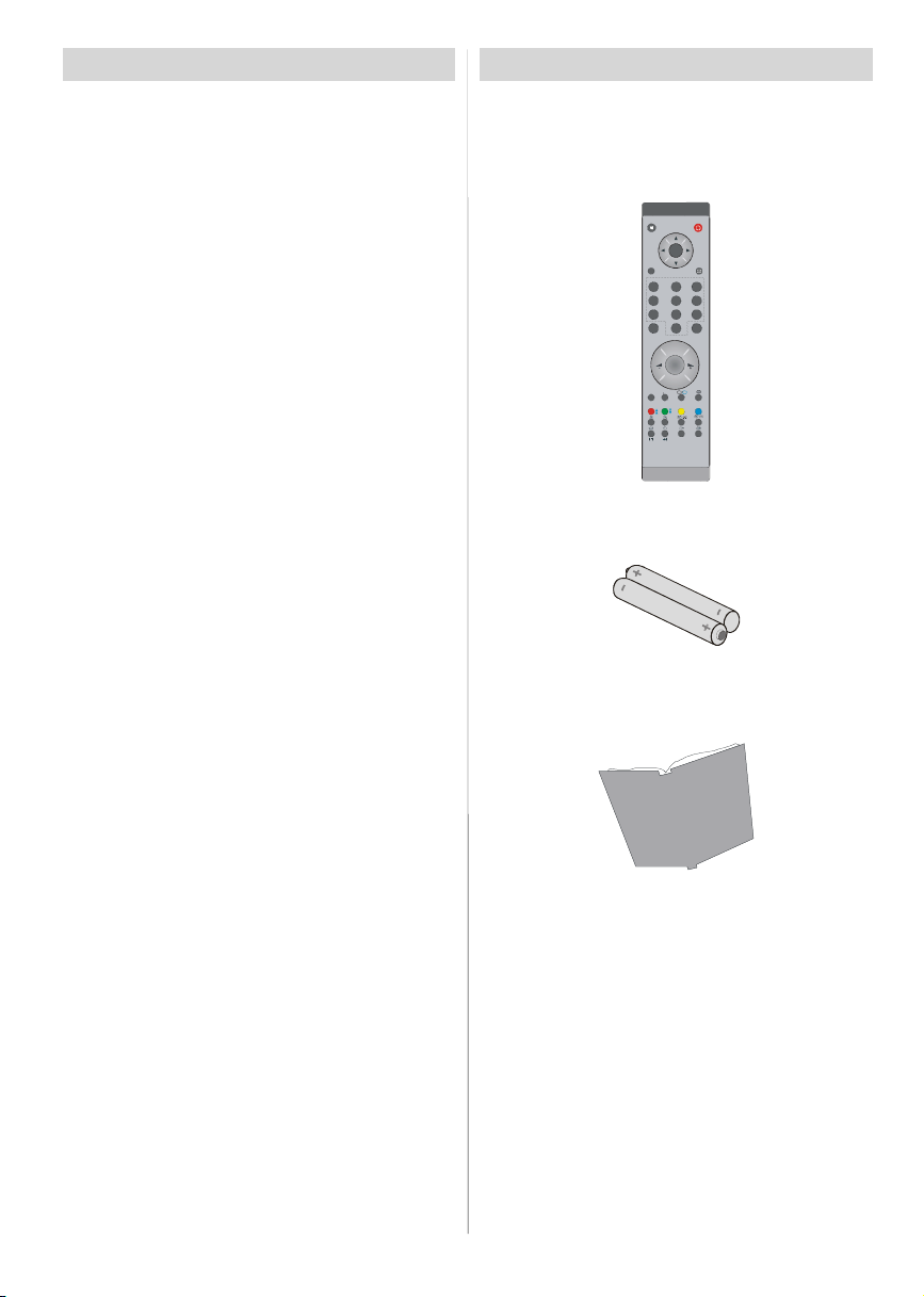
Accessories
M
OK
ABC DEF GHI
1 2 3
JKL MNO PQR
4 5 6
STU VWX YZ
7 8 9
0
PP
P -
P<P
TV
•AV in and S-Video in are available.
• Stereo sound system (3D Panorama).
•Teletext,fastext, TOP text.
• Headphone connection.
• Automatic programming system.
• Forward or backward automatic tuning.
• Sleep timer.
• Child lock.
•Automatic sound mute when no transmission.
• NTSC playback.
• PIP / PAPfunctions.
• AVL (Automatic Volume Limiting).
• When no valid signal is detected, after 5
minutes the TV switches itself automatically
to standby mode.
• PLL (Frequency Search).
• PC input.
•Plug&PlayforWindows98,ME,2000,XP,Vista.
• Audio line out.
Remote Controller
Batteries
2XAAA
Instruction Book
English -3 -
Page 5
Introduction
Thank you for choosing this
product. This manual will guide
you for the proper operation of
yourTV.Beforeoperating the TV,
please read this manual throughly.
Please do keep this manual in a safe place
for future references.
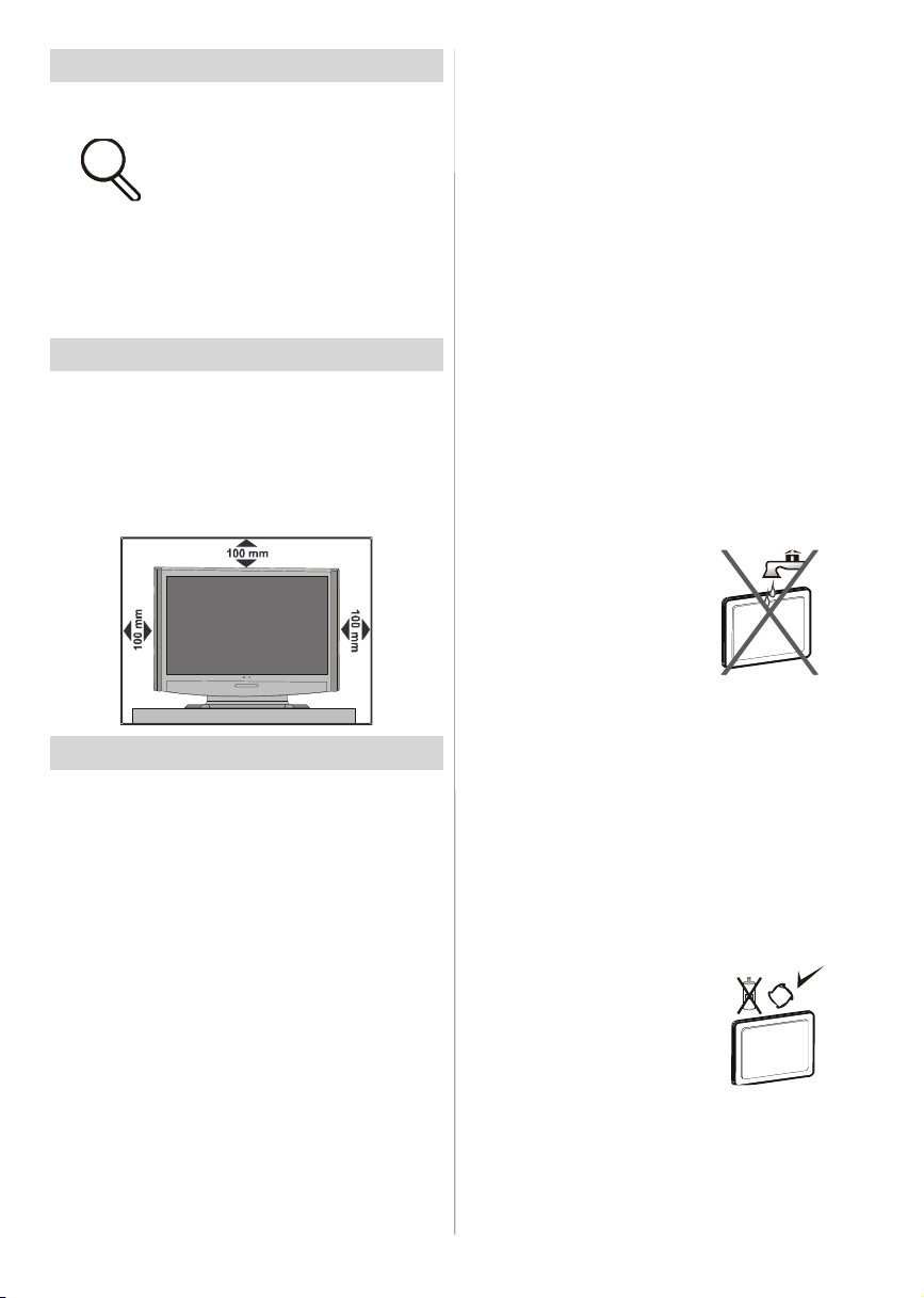
Preparation
For ventilation, leave a free space of at least
10 cm all around the set. To prevent any fault
and unsafe situations, please do not place
any objects on top of the set.
Use this device in moderate climates.
Safety Precautions
Please read the following recommended
safety precautions carefully for your safety.
Power Source
The TV set should be operated only from a
220-240 V AC, 50 Hz outlet. Ensure that you
select the correct voltage setting for your
convenience.
Power Cord
Do not place the set, a piece of furniture, etc.
on the power cord (mains lead) or pinch the
cord. Handle the power cord by the plug. Do
not unplug the appliance by pulling from the
power cord and never touch the power cord
with wet hands as this could cause a short
circuit or electric shock. Never make a knot in
the cord or tie it with other cords. The power
cords should be placed in such a way that
theyare notlikely tobe stepped on. Adamaged
power cord can cause fire or give you an
electric shock. When it is damaged and needs
to be replaced, it should be done by qualified
personnel.
Moisture and Water
Do not use this device in a humid and damp
place (avoid the bathroom, the sink in the
kitchen, and near the
washing machine). Do
not expose this device to
rain or water, as this may
be dangerous and do
not place objects filled
with liquids, such as
flower vases, on top. Avoid from dripping or
splashing.
If any solid object or liquid falls into the cabinet,
unplug the TV and have it checked by qualified
personnel before operating it any further.
Cleaning
Before cleaning, unplug
the TV set from the wall
outlet. Do not use liquid or
aerosol cleaners. Use soft
and dry cloth.
English -4 -
Page 6
Ventilation
The slots and openings on the TV set are
intended for ventilation and to ensure reliable
operation. To prevent overheating, these
openings must not be blocked or covered in
anyway.
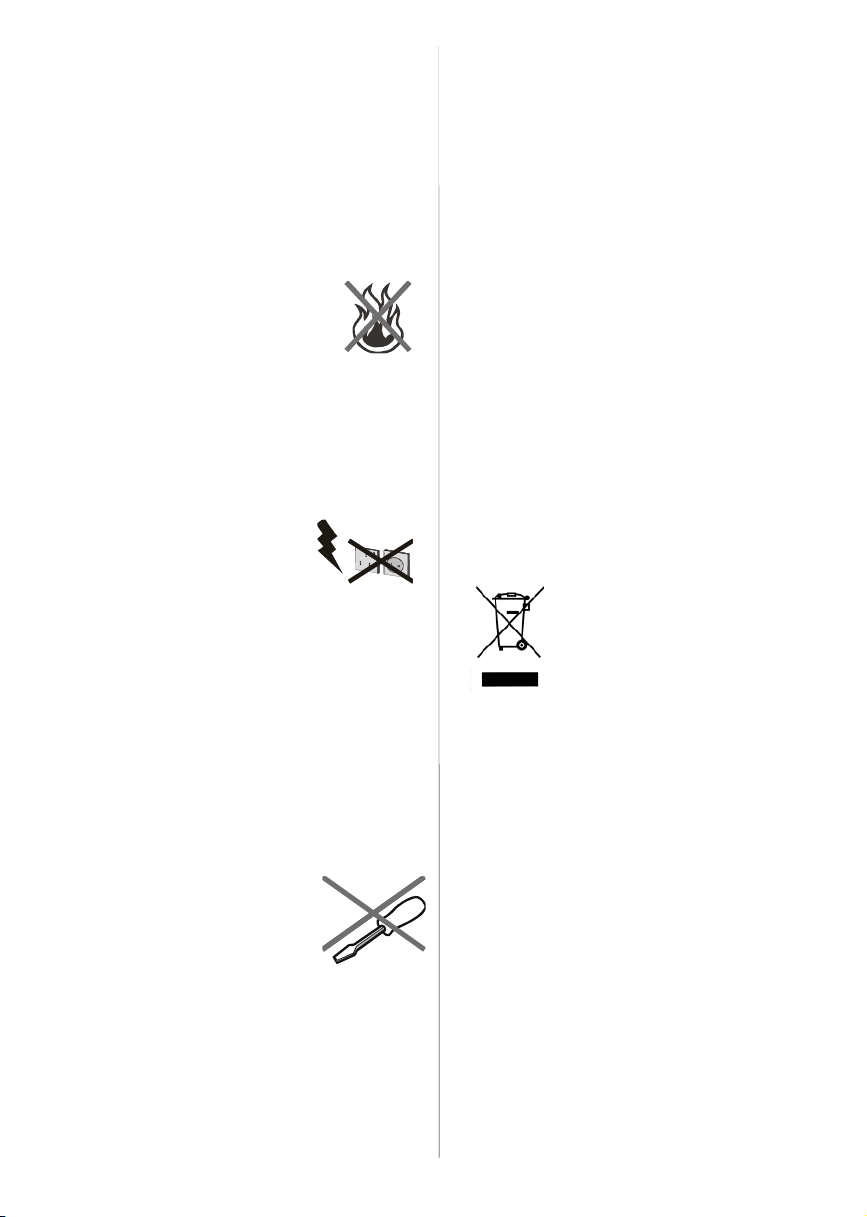
Heat and Flames
The set should not be placed
near to open flames and
sources of intense heat such as
an electric heater. Ensure that
no open flame sources, such as
lighted candles, are placed on top of the TV.
Batteries should not be exposed to excessive
heat such as sunshine, fire or the like.
Lightning
In case of storm and lightning
or when going on holiday,
disconnect the power cord from
the wall outlet.
Replacement Parts
When replacement parts are required, make
sure that the service technician has used
replacement parts, which are specified by the
manufacturer or have the same specifications
as the original one. Unauthorized
substitutions may result in fire, electrical shock
or other hazards.
Servicing
Please refer all servicing to
qualified personnel. Do not
remove the cover yourself as
this may result in an electric
shock.
Waste Disposal
Instructions for waste disposal:
•Packaging andpackaging aids are recyclable
and should principally be recycled.
Packaging materials, such as foil bag, must
be kept away from children.
• Batteries, including those which are heavy
metal-free, should not be disposed of with
household waste. Please dispose of used
battery in an environment friendly manner.
Find out about the legal regulations which
apply in your area.
• Cold cathode fluorescent lamp in LCD
PANELcontains a small amount of mercury;
please follow the local laws or regulations
for disposal.
Information for Users in European
Union Countries
This symbol on the product or
on its packaging means that
your electrical and electronic
device should be disposed at
the end of its service life
separately from your
household wastes. There are
separate collection systems for recycling in
EU.
For more information, please contact the local
authority or the dealer where you purchased
the product.
English -5 -
Page 7

Disconnecting the Device
The mains plug is used to disconnect TV set
from the mains and therefore it must remain
readily operable.
Headphone Volume
Excessive sound pressure from
earphones and headphones
can cause hearing loss.
Installation
To prevent injury,this device must be securely
attached to the wall in accordance with the
installation instructions when mounted to the
wall (if the option is available).
LCD Screen
The LCD panel is a very high technology
product with about a million thin film
transistors, giving you fine picture details.
Occasionally, a few non-active pixels may
appear on the screen as a fixed blue, green
or red point. Please note that this does not
affect the performance of your product.
Warning
Do not leave your TV in standby or operating
mode when you leave your house.
English -6 -
Page 8
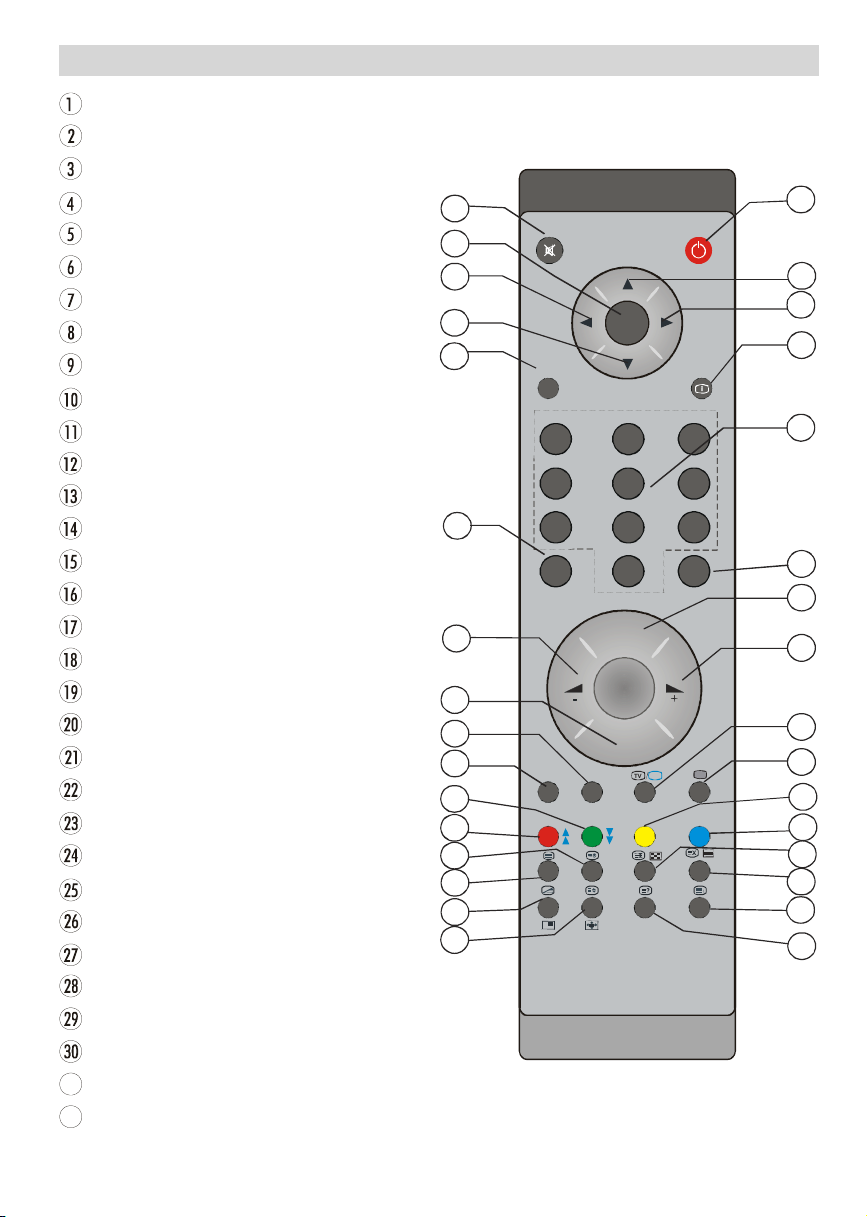
Overview of the Remote Control
31
DTV
I-II
13
Stand By
Cursor Up
Cursor Right
Info
Direct Programme
No function
Programme Up
Volume Up
TV/ DTV
External Source
Feature Menu
Installation Menu
Hold / PIP position
Update, PAP Mode
Index Page
Reveal / Switch from TV to PC
Expand / Image size
Mix / PIP mode
Teletext
Time
Page Up
Page Down
Previous Programme
Mono/Stereo - Dual I-II
Programme Down
Volume Down
Picture Mode Selection
Okay (Store)
Cursor Down
Cursor Left
Menu
Mute
32
31
30
29
28
27
26
25
24
23
22
21
20
19
18
17
M
OK
ABC DEF GHI
1 2 3
JKL MNO PQR
4 5 6
STU VWX YZ
7 8 9
PP
0
P -
P<P
TV
1
2
3
4
5
6
7
8
9
English -7 -
Page 9
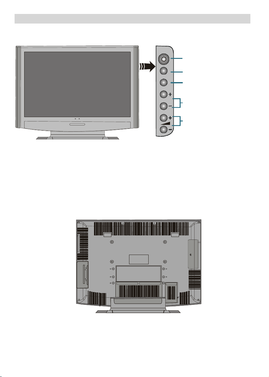
LCD TV and Operating Buttons
Standby button
FRONTVIEW
MENU
MENU
P/CH
P/CH
MENU button
Program Up/
Volume Up/
Volume Down buttons
REARVIEW
English -8-
Page 10
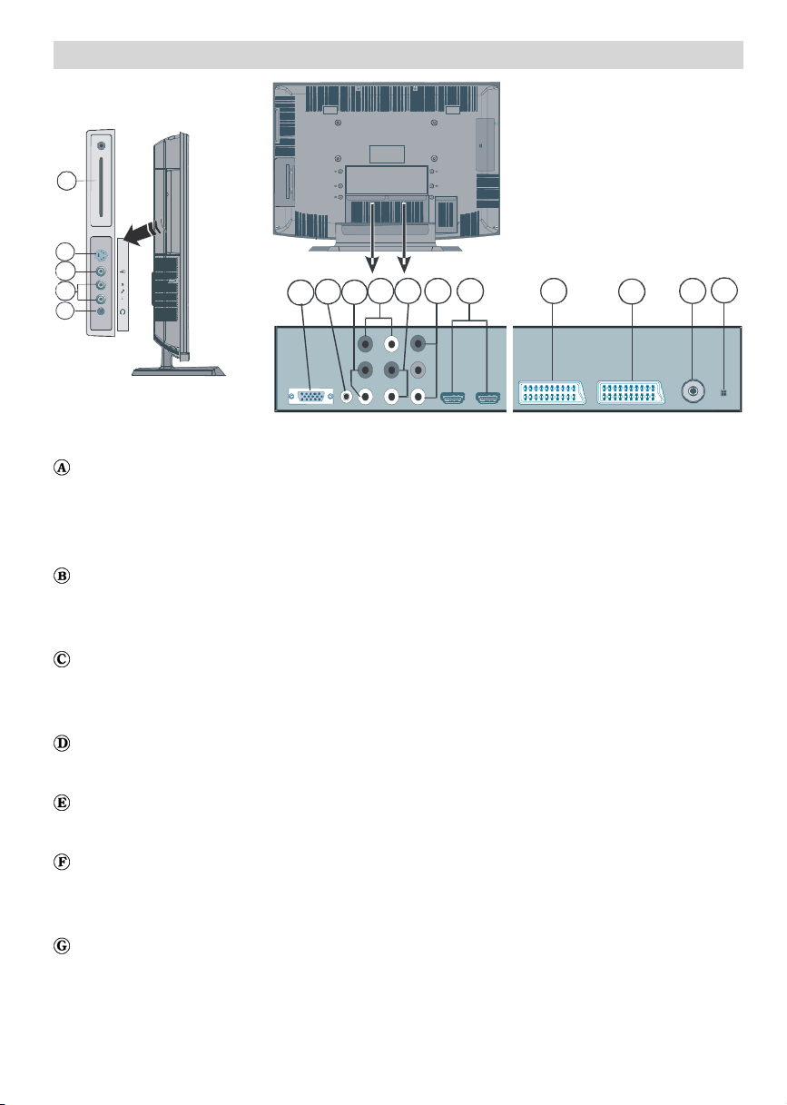
Viewing the Connections
O
A
S-VHS
B
C
D
REARVIEW
S-Video Input is used for connecting an S-Video signal (e.g. from a camcorder or VCR).
For using S-VIDEO input; connect the video cable between the S-VIDEO input on the TV and
the S-Video output on your device. Connect the audio cable between the AUDIO INPUTS
(indicated with letter C in the illustration) on the TV and the audio jacks on your device.
Video Input is used for connecting video signals of external devices.
Connect the video cable between the VIDEO IN socket on the TV and the VIDEO OUT jack on
your device.
Audio Inputs are used for connecting audio signals of external devices.
Connect the audio cable between the AUDIO INPUTS on the TV and the AUDIO OUTPUT
jacks on your device.
Headphone jack is used for connecting an external headphone to the system.
Connect to the HEADPHONE jack to listen to the TV from headphones (optional).
PC Input is for connecting a personal computer to the TV set.
G H I J K L M N
P
FE
Connect the PC cable between the PC INPUT on the TV and the PC output on your PC.
PC Audio Inputs connects to audio jacks of your PC to enable PC audio.
Connect the PC audio cable between the PC AUDIO INPUTS on the TV and audio output of
your PC.
Audio Line Outs output audio signals to an external device such as an optional sound
system.
To connect the external speakers to your TV, use AUDIO LINE OUTS of the TV with an audio
cable.
English -9 -
Page 11

Component Audio Inputs are used for connecting component audio.
Connect the audio cable between COMPONENT AUDIO INPUTS on the TV and audio outputs
of your device.
Component Video Inputs (YpBPr) are used for connecting component video.
You can connect the component video and audio sockets with a device that has component
output. Connect the component video cables between the COMPONENT VIDEO INPUTS on
on the TV and the component video outputs of your device. While connecting, be sure that the
letters on your TV, “Y”, “Pb”, “Pr” correspond with your device’s connectors.
HDMI Inputs are for connecting a device that has an HDMI socket.
Your LCD Television is capable of displaying High Definition pictures from devices such as a
High Definition Satellite Receiver or DVD Player. These devices must be connected via the
HDMI sockets or Component Socket. These sockets can accept either 720p or 1080i signals.
Also, only HDMI modes accept 1080p signals. No sound connection is needed for an HDMI to
HDMI connection.
SCART 1 inputs or outputs for external devices.
Connect the SCART cable between SCART sockets on TV and SCART socket on your external
device (such as a decoder, a VCR or a DVD player).
Note: If an external device is connected via the SCART sockets, the TV will automatically
switch to AV mode. If both sockets are employed at the sime time, SCART 1 becomes
the preferential.
SCART 2 inputs or outputs for external devices.
RF Input connects to an antenna or a cable.
Note that if you use a decoder or a media recorder, you should connect the aerial cable
through the device to the television with an appropriate antenna cable, as shown in the
illustration below.
This connector is for service use only..
CI Slot and SPDIF Out. CI Slot is used for inserting a CI card.A CI card allows you to view all
the channels that you subscribe to. For more information, see “Common Interface” section. S/
PDIF Out is used for transferring digital audio signals. Use an RCA cable to transfer audio
signals to a device that has S/PDIF input.
Subwoofer Out is for connecting an external, active subwoofer to the set to give a much
deeper bass effect.
Use an appropriate RCA cable to connect the set to a subwoofer unit.
English -10-
Page 12
Power Connection
IMPORTANT: The TV set is designed to operate on 220-240V AC, 50 Hz.
• After unpacking, allow the TV set to reach the ambient room temperature before you
connect the set to the mains.
• Plug the power cable to the mains socket outlet.
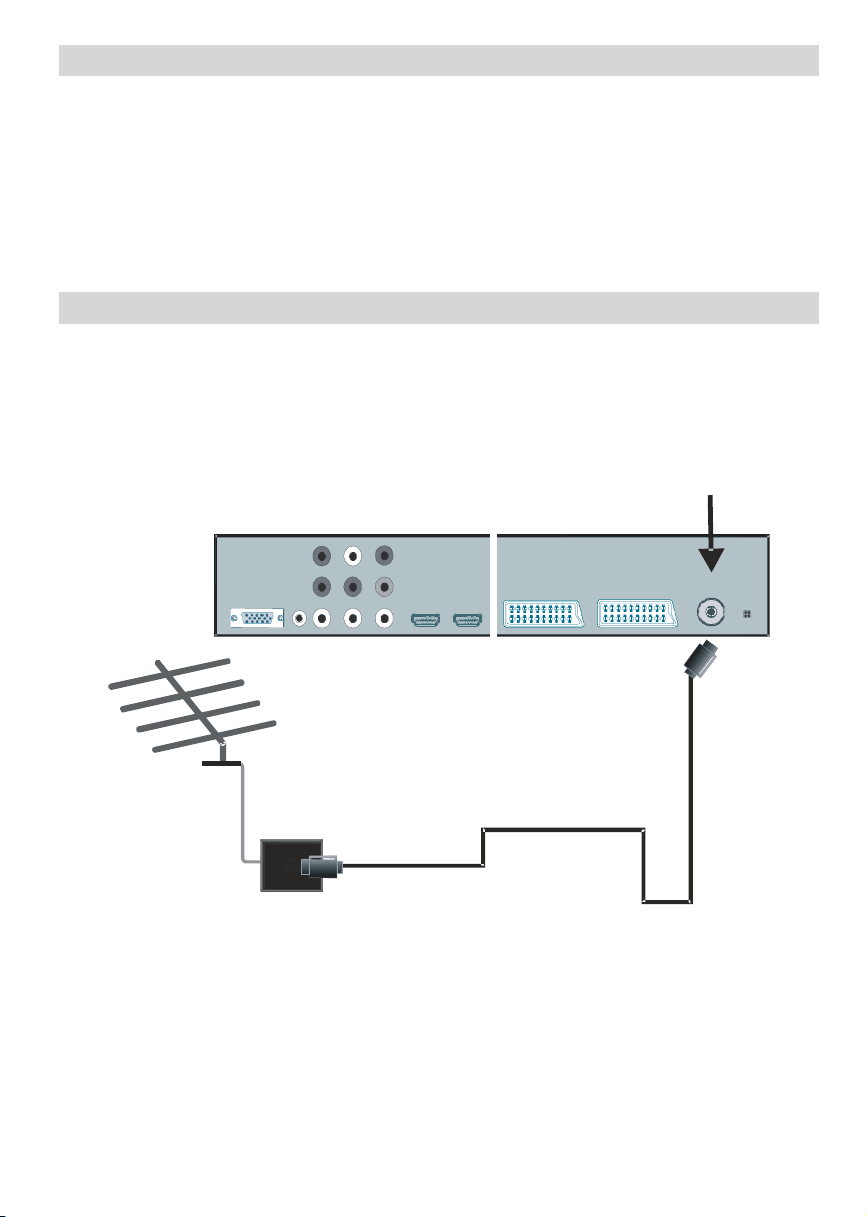
Aerial Connection
• Connect the aerial or cable TV plug to the AERIAL INPUT socket located at the rear of the TV.
English -11-
Page 13
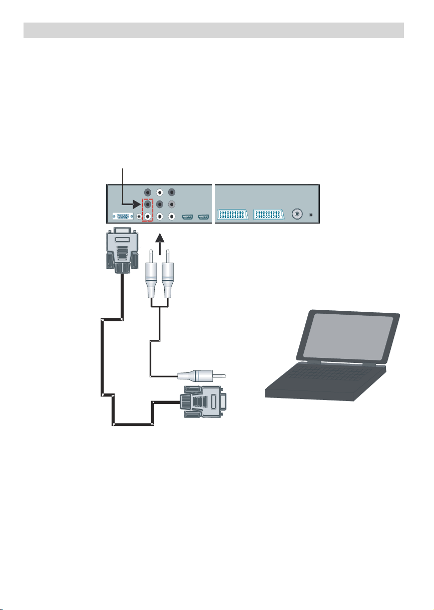
Connecting the LCD TV to a PC
(not supplied)
For displaying your computer’s screen image on your LCD TV,you can connect your computer
to the TV set.
• Power off both computer and display before making any connections.
• Use 15-pin D-sub display cable to connect a PC to the LCD TV.
• When done, switch to PC source. See, “Input selection” section.
• Set the resolution that suits your viewing requirements.
inputs
REARVIEW
PC RGB cable
(not supplied)
to PC RGB output
English -12-
Page 14
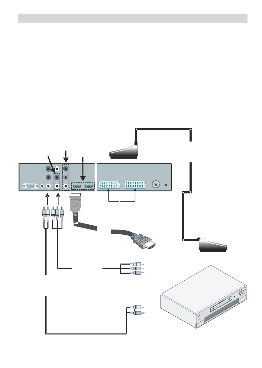
Connecting to a DVD Player
SCART
If you want to connect a DVD player to your LCD TV, you can use connectors of the TV set. DVD
players may have different connectors. Please refer to your DVD player’s instruction book for
additional information. Power off both the TV and the device before making any connections.
Note: Cables shown in the illustration are not supplied.
• If your DVD player has an HDMI socket, you can connect via HDMI. When you connect to DVD
player as illustrated below, switch to HDMI source. See, “Source menu” section.
• Most DVD players are connected through COMPONENT SOCKETS . Use a component video
cable to connect video input. For enabling audio, use a component audio cable as illustrated
below. When done, switch to YPbPr source. See, “Input selection” section.
• You may also connect through the SCART 1 or SCART 2. Use a SCART cable as shown
below.
Component
Component
audio
inputs
video
inputs
HDMI
inputs
Component
audio
cable
video
cable
HDMI
cable
SCART
sockets
English -13-
Page 15
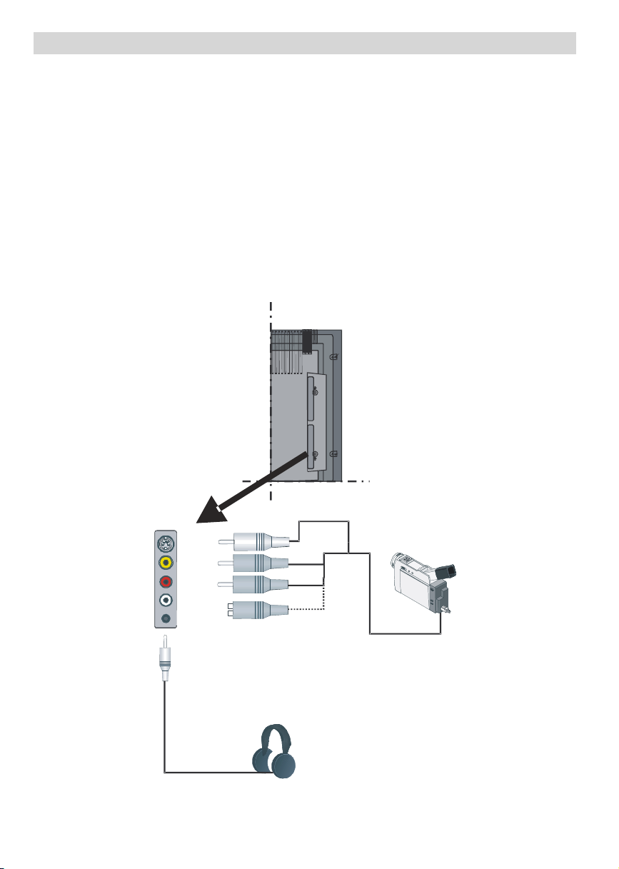
Using Side Connectors
You can connect a range of optional equipment to your LCD TV. Possible connections are
shown below. Note that cables shown in the illustration are not supplied.
• For connecting a camcorder, connect to the S-VIDEO or VIDEO IN socket and the AUDIO
SOCKETS. Do not connect the camcoder to S-VIDEO and VIDEO IN socket at the sime time
since it can cause noise in the picture. For selecting the related source, see the section
“Input selection” in the following parts.
• To connect external speakers, use an audio cable. Do not reverse the AUDIO LEFT and
AUDIO RIGHT jacks. Turn on the LCD TV and external speaker set after all connections are
made. Refer to your speaker set’s manual for further queries.
• To listen the sound from headphones, connect to the HEADPHONE jack of theTV.
• For connecting a subwoofer,connect to the SUBWOOFER OUT .
English -14-
Videocamera
Page 16

Inserting Batteries in the
Remote Control Handset
WARNING: Re m ot e c o nt ro l is b at t e r y
included. A plastic protector is
used to disconnect the batteries
in order to prevent the battery life
from reducing. Please remove
the plastic protector before the
first use.
•Remove the battery coverlocated onthe back
of the handset by gently pulling backwards
from the indicated part.
• Insert two AAA/R03 or equivalent type
batteries inside. Place the batteries in the
right directions and replace the battery cover.
Operating Range for the
Remote Control
• Point the top of the remote control toward
the LCD TV's remote sensor LED while
pressing a button.
M
OK
ABC DE F GHI
1 2 3
JKL MNO
PQR
4 5 6
STU V WX YZ
7 8 9
PP
0
P-
P<P
Note: Remove the battery from remote control
handset when it is not to be used for a
long perio d . Ot h e r w i s e it c a n b e
damaged due t o a n y le a k a ge of
batteries.
English -15-
Remote range is approximately 7m/23ft.
Page 17

Switching the TV On/Off
To Switch the TV On
• Connect the power cord to the 220-240V AC.
• Press STANDBY button. Then the standby
LED lights up.
Note: These explanations are valid for the
navigation of the whole menu system.
To select options that are explained in
the following parts, refer to “Navigating
the Menu System”.
• Toswitchonthe TVfromstandbymode either:
• Press the button, P+ / P- or a numeric
button on the remote control.
• Press the -P/CH or P/CH+ button on the TV.
The TV will then switch on.
Note: If you switch on your TV via PROGRAM
UP/DOWN buttons on the remote control
or on the TV set, the programme that
you were watching last will be reselected.
To Switch the TV Off
• Press the button on the remote control or
STANDBY button on the TV, so the TV will
switch to standby mode.
• To power down the TV completely, unplug
the power cord from the mains socket.
Navigating the Menu System
Fornavigation
To confirm
choices
SELECT
OK
• Press M to display the main menu.
• Press
or button to select an icon. Press
or OK button for more options.
• Use
• Press
or button to highlight.
or buttons tochange the settings.
Press OK to set as default.
• To exit the menu or return from sub-menu
screen, press M.
M
INFO
Initial Settings
When the TV set is operated for the first time,
the IDTV turns on first.
Becausethis is thefirsttimetheTV is used, there
are no channels stored in the memory and the
following message appears on the screen:
Please ensure aerial is plugged in. Do you
want to start first time installation?
Yes No
• To start installation process, select “Yes”,
to cancel select “No”.
• Toselect the“Yes” or “No” option, highlight
the item by using
the OK button.
The IDTV will automatically tune to the UHF
transmision channels 21 to 68, searching for
digital terrestrial TVbroadcasts and displaying
the names of channels found. This process
will take about five minutes. To cancel
searching, you can press the M button at any
time during the process.
AUTOMATIC SEARCH
Channels:
BBCONE
BBCTWO
BBCCHOICE
Searching UHF channels30.Pleasewait.Thiswill take afew minutes
12 %
MENU
Cancel search
After Automatic Search is completed, the
following message askingfor analoguechannel
search appears on the screen:
or buttons and press
English -16-
Page 18

Do you want to search for
analogue channels?
Yes
No
To seach foranalogue channels, select “Yes”.
TV switches to the analogue TV mode. The
menu below is displayed to search for
analogue channels:
AUTO PRO GRAM
Select your Language, Country and Text
language by using
or and
/
buttons.
Press OK button to continue. To cancel, press
the BLUE button.
For more information on this process, see
“Install Menu” section.
NOTE: For proper functioning of digital teletext
in DTV mode, you should set country
as UK in analogue AUTO PROGRAM.
Basic Operations
You can operate your TV using both the
remote control and onset buttons.
Operation with the Buttons on the TV
Volume Setting
• Press - button to decrease volume or
+ button to increase volume, so a volume
level scale (slider) will be displayed on the
screen.
Programme Selection
• Press P/CH + button to select the next
programme or P/CH - button to select the
previous programme.
Entering Main Menu
• Press the MENU button to enter main menu.
In the Main menu select sub-menu using P/
CH - or P/CH + buttons and enter the sub-
menu using
the usage of the menus, refer to the menu
system sections.
AV Mode
• Press the TV/AV button at the control panel
on the the TV to switch your TV toAVmodes.
Operation with the Remote Control
• The remote control of your TV is designed to
control all the functions of the model you
selected. The functions will be described in
accordance with the menu system of your
TV.
- or + buttons. Tolearn
•Functions of the menu system are described
in the following sections.
English -17-
P -
Page 19

Volume Setting
Press V + button to increase the volume.
Press V - button to decrease the volume. A
volume level scale (slider) will be displayed
on the screen.
Programme Selection (Previous or
Next Programme)
• Press P - button to select the previous
programme.
• Press P + button to select the next
programme.
Programme Selection (Direct Access)
•Press numeric buttons on the remote control
to select programmes between 0 and 9. The
TV will switch to the selected programme.
To select programmes between 10 - 999 (for
IDTV) or 10-99 (for analogue), press the
numeric buttons consecutively (eg. for
programme 27, first press 2 and then 7).
When the pressing time is due for the second
numeric button, onlythe first digit programme
will be displayed. The limit of the delay time
is 3 seconds.
• Press directly the programme number to
reselect single digit programmes.
Everyday Operation
Pressing the
while watching television programmes will
switch the TV set between the digital terrestrial
television broadcasting and its normal
analogue broadcasting.
Information Banner
• Whenever you change channel, using the P-
/ P+ button or the numeric buttons, the TV
displays the broadcast picture along with an
information banner at the bottom of the
screen. This will remain on the screen for
approximately three seconds.
TV
button at any time
English -18-
• The information banner can also be
displayed at any time while watching TV by
pressing the
button on the remote
control:
Now: 50/50
Next:Ace Lighting
1. BBC ONE
Signal Level:
09:25 - 11:00
11:00 - 11:25
13:15
• The information banner gives information
on the channel selected and the
programmes on it. The name of the channel
is displayed, along with its channel list
number and an indication of the strength of
the signal received.
Hint: Not al l c han nels b r o a dc ast the
programme data. If the name and time
of the programme are not available,
then “No Information Available” will be
displayed in the information banner.
• Icons are also displayed in the information
banner and if this channel is a favourite
channel, favourite channel icon “
” will
also be displayed.
If the selected channel is locked, you must
enter the correct four numeric code to view
the channel. “E nt er L o c k K e y” will be
displayed on the screen in such a case:
EnterLock Key
Electronic Programme Guide (EPG)
• Some, but not all, channels send information
about the current and next events.
•Please note that event information is updated
automatically.If there is no event information
data available in channels, only channel
names with “No Information Available”
banner is displayed.
Page 20

• Press GUIDE button to view the EPG menu.
•In EPGmenu, you can easily see the extended
help information by pressing
button.
• Press this button again to close this window.
• In the EPG menu, all channels are displayed.
Current channel is highlighted. Use
or
buttons to change channels. Also press
GREEN/RED buttons to scroll up/down the
pages for the channels.
• If you highlight an event, short event
description, extended event description, start
and end times of the event will be displayed
on the screen.
• If you press the OK button when a next event
is highlighted, a reminder is set for the
highlighted programme and a clock appears
across the highlighted channel line.
Programme reminders can be set to signal
that a programme is about to start when you
are watching another channel. If you set
reminder for a programme, then you will be
asked for switching to that channel when the
reminder time is reached.
• Press the M button to view the 7 day EPG.
• Press
or button to navigate in Channels
or Programmes.
• Press
or button to navigate through the
channel and programme list.
ELECTRONICPROGRAMMEGUIDE(7 Day) Saturday 21/8 13:49
Triplebill. In the Ring/Romany Days/On theRadio: Paul and Barry
grapplewith the world of wrestling;hunt for a mysterious Emperor's
underpants;and record their first pop song.
Channels Programmeson Saturday 21/8, 13:00 - 15:00
30. CBBC Channel 13:00 ChuckleVision (Now)
40. BBC NEWS24 14:00Tracy Beaker
41. ITV News 14:55Newsround
50. Four Text
800. BLUE/LEFT 1k...
801. CCIR17/1kHz...
Navigate
Day
BLU E you can advance the schedule
backward/forward of a day.
• If you press
button you can see the
detailed help information easily. Press
button again to exit help menu.
• The starting time for EPG isthe current time.
You can see the event information for the
next two hours. By pressing
or button,
you can go to the next/previous hours while
Programmes list is highlighted.
• lf you press the OK button when a next event
is highlighted, a reminder is set for the
highlighted programme and a clock appears
on the screen.
• Programme reminders can be set to signal
that a programme is about to start when you
are watching another channel. If you set
reminder for a programme, then you will be
asked for switching to that channel when the
reminder time is due.
ELECTRONIC PROGRAMME GUIDE(7 Day) Saturday 21/8 13:51
Newsround 16:55-17:00
CBBC joins the Newsroundteam, keeping you up to date on the latest
storiesand eventshappening at home and abroad.
Channels Programmeson Saturday 21/8, 15:00 - 17:00
30. CBBC Channel 15:00 Even Stevens
40. BBC NEWS24 15:50 NewsroundShowbiz
41. ITV News 16:00Basil Brush
50. Four Text 16:55 Newsround
51. BBCI
800.BLUE/LEFT1k...
801.CCIR17/1kHz...
DayNavigate
Displaying the Subtitles
With digital terrestrial broadcasting (DVB-T),
some programmes are broadcast with
subtitles. Subtitles can be displayed while
watching these programmes.
Press the M button to display the main menu,
highlight the Configuration line using
or
• With RED/GREEN buttons, you can change
the schedule time. By pressing YELLOW/
English -19-
Page 21

button and press the OK button to display the
while subtitles are on. Would you like
configuration menu.
Highlight the “Subtitle” item in configuration
menu and use
or button to set Subtitle to
Off or a language.
If “Subtitle” is on and a language option is
set, pressing the
button causes the
following warning message display on the
screen:
to turn subtitles off now?
NoYes
Digital Teletext
With digital terrestrial broadcasting (DVB-T),
in addition to pictures and sound, you can also
view digital teletext.
Digital teletext is sometimes broadcast at the
same time with the normal broadcasting.
• Press the
• The digital teletext information appears.
• Operate it with the coloured buttons,
buttons and OK button.
The operation method may differ depending
on the contents of the digital teletext.
Follow the instructions displayed on digital
teletext screen.
• When “Press SELECT” button or similar
message appears on the screen, press the
OK button.
button.
/ / /
• The aspect ratio when watching a channel
with just digital teletext broadcasting is the
same as the aspect ratio of the picture viewed
previously.
• When you press the
(Text) button again,
the digital teletext screen will be displayed.
Over Air Download
To ensure that your IDTV always has the most
up-to-date information, please ensure that,
after use, it is set to standby mode. At 3 A.M.
each day, the IDTV automatically searches for
any updates which may be broadcast and will
download this to your IDTV automatically.This
operation will normally take approximately 30
seconds.
If you want to perform this, you need to set
Automatic Downloadto“Enabled” in Receiver
Upgrade setting.
Widescreen
Depending on the type of the broadcast being
transmitted, programmes can be viewed in a
number of formats. Press the WIDE button
repeatedly to select between Auto, Full, 4:3,
Panoramic, 14:9 Zoom, Cinema or 16:9
Subtitle.
When Auto is selected, the format being
displayed is determined by the picture being
broadcast.
PLEASE NOTE: Menu s i ze c h a n g es
dependi n g on th e
chosen image size.
• When the
(Text) button is pressed, the
TV returns to television broadcasting.
• With digital terrestrial broadcasting (DVBT), in addition to digital teletext broadcasting
together with the normal broadcasting, there
are also channels with just digital teletext
broadcasting.
English -20-
Page 22

IDTV Menu System
CHANNELLIST 1 BBC ONE
The IDTV menu can only be viewed when
watching digital terrestrial broadcasting.
Press the
while the TV is in analogue mode.
Press the M button. The menu below appears
on the screen:
Channel List
Using the or button on the remote control,
make sure that the first item, Channel List, is
highlighted and press the OK button to display
the Channel List.
The following operations can be performed
in this menu:
• Navigating the entire list of channels
• Deleting channels
• Renaming channels
• Adding locks to channels
• Setting favourites
Channel List is the place where the channels
are managed.
TV
button to turn IDTV on
Main Menu
Channel List
Installation
Timers
Language
TV Setup
Common Interface
1. BBCONE
2. BBCTWO
3. ITV8
4. Channel 4
5. BBCTHREE
6. Teletext
7. BBCFOUR
8. SkyTravel
9. UKHistory
10. RTL
Select Delete EditName Lock Favourites
Function SelectChannel Watch More
Navigating the Entire Channel List
Press or button for selecting the previous
ornext channel.Youcanpress RED or GREEN
button to move page up or page down.
To watch a specific channel, highlight it using
or button and then pressOK button,while
the “Select” item on Channel List menu is
highlighted by using
or button.
Then the name and number of the selected
channel will be displayed in the top-left and
top-right of the channel display at the top-right
of the screen, respectively.
Deleting the Channels in the Channel
List
Press or button to select the channel
that will be deleted.
Press
on Channel List menu. As seen on Channel
List menu, SELECT is displayed nextto Delete
item at the bottom of the screen to indicate that
you must press the OK button to delete the
highlighted channel in the channel list.
or buttonto select the “Delete’’item
English -21-
Page 23

1. BBC ONE
i
SELECT
CHANNELLIST 1 BBC ONE
2. BBC TWO
3. ITV 8
4. Channel 4
5. BBC THREE
6. Teletext
7. BBC FOUR
8. Sky Travel
9. UKHistory
10. RTL
Select Delete EditName Lock Favourites
Function Select Channel Delete More
Press the OK button to delete the highlighted
channel in the channel list. Then the message
below appears on the screen:
The selectedservice will be permanently
deleted.Are you sure?
Yes No
Press or button to highlight the desired
option. If OK button is pressed while “Yes” is
highlighted, the highlighted channel is
deleted. Selecting “No” cancels the deletion.
Renaming Channels
To rename a specific channel, the channel
must be highlighted by pressing
button. Then highlight the Edit Name item by
pressing
or button as illustrated below..
Press the OK button to activate the rename
feature.
or
character becomes ‘a’ by
and ‘c’ by .
Pressing the numeric buttons ‘0...9’ replaces
the highlighted character with the characters
printed above the button one by one as the
button is pressed.
Press the M button to cancel the editing orOK
button to save the new name.
Adding Locks to Channels
Channel locking provides a passwordprotected access to channels selected by
parents. In order to lock a channel you should
know the parental lock password (default
value is set to 0000 in the factory and can only
be changed from the Configuration menu).
Select the channel to be locked by highlighting
it and select the Lock option by pressing
button. When the OK button is pressed, a
dialog OSD asking for the password will be
displayed.
1. BBC ONE
2. BBC TWO
3. ITV 8
4. Channel 4
5. BBC THREE
6. Teletext
7. BBC FOUR
8. Sky Travel
9. UKHistory
10. RTL
Select Delete Edit Name Lock Favourites
Function Select Channel Lock/Unlock More
or
1. BBC ONE
2. BBC TWO
3. ITV 8
4. Channel 4
5. BBC THREE
6. Teletext
7. BBC FOUR
8. Sky Travel
9. UKHistory
10. RTL
Select
Delete Edit Name Lock Favourites
Function SelectChannel Edit Name More
Now pressing or button moves to the
previous/next character. Pressing
button toggles the current character, i.e., ‘b’
Enter the password by using the numeric
buttons on the remote control. The lock icon
“
channel. Repeat the same operation to cancel
the lock.
Setting Favourites
or
English -22-
You can set various channels as favourites
so that only the favourite channels are
EnterLock Key
” will now be displayed next to the selected
Page 24

navigated. To set a favourite you should
highlight the Favourites item at the bottom of
the Channel List menu.
Use the
or button to highlight the
“Favourites” item at the bottom of the screen
and then, in turn, highlight each channel you
want to add to the favourites list, using the
and buttons (or red/green buttons), and
press the OK button.
A channel selected as a favourite appears in
the main channel list with a favourites icon
(
) against the channel name as illustrated
below:
1. BBC ONE
2. BBC TWO
3. ITV 8
4. Channel 4
5. BBC THREE
6. Teletext
7. BBC FOUR
8. Sky Travel
9. UKHistory
10. RTL
Select Delete Edit Name Lock Favourites
Function Select Channel Add/Remove... More
On Screen Help
For all menus, press the button to display
the help informationabout the menu functions.
For Channe l List menu the following
message is displayed on the screen:
highlighted channel.
Press MENU to exit this screen.
Installation
The Installation menu is mainly intended to
help you for creating a Channel Table in the
most efficient way.
English -23-
Main Menu
Channel List
Installation
Timers
Language
TV Setup
Common Interface
This menu includes the following items:
• Add New Channels.
• First Time Installation.
Add New Channels
This tuning menu consists of two parts:
•Automatic Search
• Manual Search
Installation
Add New Channels
First Time Installation
Automatic Search
Automatic search is started by pressing the
OK button in the auto-search pop up menu.
All the services will be searched and a channel
table will be created automatically.
All channels found are stored in a sorted form
with respect to their channel numbers. Some
services may not appear with the correct
channel number. This may occur due to
missing information when the broadcaster
does not transmit any channel information.
Manual Search
In manual search, the number of the multiplex
is entered manually and only that multiplex is
searched for the channels. For every valid
channel number, signal level, signal quality
Automatic Search
Manual Search
Page 25

and network name are shown at the bottom
Country UK
Text language West
of the screen.
In both manual and auto search, any existing
channel in the database is not re-stored to
avoid redundant duplicates of that channel.
First Time Installation
The user can use this item to load default
settings, which were loaded to the receiver at
the factory.
To install factory settings, highlight “First Time
Installation” menu and press the OK button.
Installation
Add New Channels
Then you will be asked to confirm for deleting
all channels and settings:
Yourprevious digital channel list will be destroyed.
Are you sure you wantto delete all digital channels
and settings for first time installation?
Yes
No
By selecting Yes and pressing the OK button,
the existing channel table will be deleted.
After factory settings are loaded, “First Time
Installation” menu will be displayed:
Please ensure aerial is plugged in. Do you
want to start first time installation?
Yes No
Press the OK button to start installation. After
search is completed for digital channels, a
message asking whether to search for
analogue channels appears on the screen:
Do you want to search for
analogue channels?
Yes
No
AUTO P ROGRA M
Select your Language, Country and Text
language by using
or and
/
buttons.
Press OK button to continue. To cancel, press
BLUE button. The following menu will be
displayed during the APS process:
After APS is finalized, the programme table
will appear on the screen. In the programme
table you will see the programme numbers
and names assigned to the programmes.
If you do not accept the locations and/or the
programme names, you can change them in
the program table.
Configuration
Press the M button to display the main menu
and press the
Configuration. Then press the OK button to
display the configuration menu. Press the M
button to leave the menu screen.
button twice to highlight
Press the OK button to search for analogue
channels. The following menu appears on
the screen for analogue channel search:
English -24-
Page 26

Main Menu
Channel List
Installation
Timers
Language
TV Setup
Common Interface
The various configuration functions are
displayed in a list, along with a quarter-screen
image of the currently selected channel. You
can select a function by highlighting the
corresponding menu line using the
or
button. Configuration menu will look like this:
AudioLanguage
Subtitle
FavouriteMode
EPG Preference
ReceiverUpgrade
English
Off
Off
Now&Next
V.1.5
More
Audio Language
Digital terrestrial television channels can
broadcast simultaneous soundtracks in more
than one language. This function selects
which language soundtrack you will hear
when switching to a channel broadcasting with
the multiple soundtracks.
Highlight the Audio Language line in the
Configuration menu and use the
or
button to cycle through the language options.
Subtitle
Digital terrestrial television channels can
broadcast subtitles displayed on the screen
for hard-of-hearing people. This function
selects the desired subtitle language and
enables the automatic display of subtitles
whenever subtitle information is broadcast.
Highlight the Subtitle line in the Configuration
menu and use the
or button to cycle
through “Off” and language options.
Favourite Mode
This function enables or disables the favourite
channel list mode.
Use
or button to turn on/off favourite
mode. If the “Favourite Mode” is on; while in
normal operating mode, pressing P+ and P-
buttons will only navigate through the
channels that were previously defined as
favourites in the channel list.
EPG Preference
Digital terrestrial television channels can
broadcast simultaneous Next&Now and 7-
Day electronic programme.
Highlight the EPG Preference line in the
Configuration menu and use the
or
button to select Next&Now or 7-Day.
Receiver Upgrade
The IDTV can be upgraded via the
configuration menu, entered from the main
menu.
In the configuration menu, highlight the
“Receiver Upgrade” item by pressing
button and press the OK button to start
upgrade process.
There are two options for receiver software to
be upgraded: automatic and manual.
or
English -25-
Page 27

Audio Language
Installation
Subtitle
FavouriteMode
EPG Preference
ReceiverUpgrade
AutomaticDownload
Searchfor New Version
MENU
Exit More
English
Off
Off
Now&Next
V.1.5
Enabled
Automatic Download (Automatic Upgrade)
Automatic Download can be enabled or
disabled by pressing
or button. If it is
enabled, then there are two ways for
automatic upgrade:
• The first one is checking the existence of a
new software every time the IDTV goes to
standby.
• The second one is being activated at 03:00
A.M.every night, provided that the IDTVis left
in standby mode.
• Both automatic upgrade methods result in
standby mode either the upgraded or not.
If the automatic upgrade is set to “Disabled”
then this function will not work.
Search for New Version (Manual Upgrade)
Manual upgrade starts if the “Search for New
Version” item is highlighted by using
or
button and activated by pressing the OK
button.
After “Search for New Version” is activated,
the IDTV tunes to each frequency that have
been stored in its database and looks for the
new software. During this process, the
following OSD is displayed:
Software Upgrade
Searchingfor upgrade.Please wait, or
press MENU to cancel.
Search Progress:
English -26-
Parental Settings
Some channels broadcast material which you
do not want younger members of the family to
watch. Any channel can be ‘locked’ so that it
cannot be selected for viewing unless a four-
digit PIN code is entered. In this way, any
channel not suitable for younger viewers can
be prohibited.
This function enables or disables the menu
protection system and allows the PIN code to
be changed.
Use
Settings option. Press the OK button to enter
Parental Settings menu. A dialog box asking
for the lock key is displayed:
There is only one key which is set to “0000”
initially. Enter lock key. If wrong lock key is
entered, the following message is displayed
and the TV then returns to the previous menu:
If it is correct, the Parental Settings menu will
be displayed including the following items:
Here, you can set/reset locking for the main
menu or the installation menu to restrict
access. If the menu lock is disabled, there
will be free access to the menu system. Also
in this menu you can change the lock key and
set/change parental lock mode.
Disabled: All menus are unlocked.
Main Menu:Mainmenuisaccessible onlywiththe
or button to highlight Parental
EnterLock Key
Menu Lock
Set Lock Key
correct lockkey. So the user cannot
add, delete, rename, or move the
channelsand cannot set the timers.
Page 28

Installation: Installation menu is locked, so
the user cannot add channels.
Note: Changes will be updated after exiting
configuration menu.
Timers
You can set a timer to switch the TV to any
channel without your intervention. This is also
useful for recording the programmes when
you are out.
Display the main menu by pressing the M
button. Highlight the Timers line by pressing
or button and press the OK button to
display the Timer menu:
Main Menu
Channel List
Installation
• To set an event, highlight its mode button
using the
or button and press the OK
button to display the timer entry window.
Start:
End:
Date:
Mode:
3. ITV 1
00:00
00:00
03/06/2005
Once
• Here the five settings consisting of the
channel name, start time, end time, date and
frequency mode can be set. You can move
freely between each setting using the
or
buttons.
• The channel name is set using the
or
button to display the channel which
broadcasts the programme.
• The start time, end time and date are each
set with the numeric buttons on the remote
control in 24-hour format.
Timers
Language
TV Setup
Common Interface
Up to five separate timer events can be set
and each is displayed in the Timer screen,
showing the event number, the channel to be
selected, the start time, end time, date and
the mode - whether that event is active (and
will be acted on) or not.
TIMERMENU
2. BBCONE 00:00 00:00 01/01/2005 Inactive
3. BBC ONE 00:00 00:00 01/01/2005 Inactive
4. BBCONE 00:00 00:00 01/01/2005 Inactive
5. BBCONE 00:00 00:00 01/01/2005 Inactive
6. BBCONE 00:00 00:00 01/01/2005 Inactive
Toggle Mode Exit Edit Timer More
MENU
English -27-
• The frequency mode determines how often
the receiver operates this event and is set
with the
or button to be either Once,
Daily,or Weekly.
If an invalid number for the start or end times
or the date is entered, “Entered time is not
va li d ” message appears on the menu
screen.
If timer action occurs while the TV is being
watched, the TV switches to the selected
channel. When timer expires, the TV switches
back to the channel which it is switched from.
Selected digital channel will be output via
Scart-2.Youshouldconnect yourVCRto Scart-
2 for recording digital broadcasts.
Language
Some programmes are broadcast in two or
more languages simultaneously. The
language thus can be selected from the
Language menu.
• Press the M button to display the main menu
Page 29

and use or button to highlight the
Language line and press the OK button:
Main Menu
Channel List
Installation
Timers
Language
TV Setup
Common Interface
You can find detailed information for all menu
items in “Analogue TV Menu System” section.
Common Interface
• Press the M button to display the main menu
and use the
“Common Interface” line and press theOK
button:
or button to highlight the
Main Menu
Channel List
Installation
• Use the or button to highlight the
soundtrack language required and press the
OK button. Normal viewing, with the required
language soundtrack, can be resumed by
pressing the M button.
Languages
English
TV Setup
You can use this item to display the TV
functions.
The digital TV Setup menu screen is
accessed from the main menu. Press the M
button to display the main menu and use
or button to highlight “TV Setup” ,press the
OK button to display TV Setup menu screen.
Main Menu
Channel List
Installation
Timers
Language
TV Setup
Common Interface
Timers
Language
TV Setup
Common Interface
It is required to subscribe to a pay channel
company to view the pay channelsof the digital
terrestrial broadcasting.
Obtain the Conditional Access Module (CAM)
and the viewing card by subscribing to a pay
channel company, then insert those to the TV
using the following procedure.
• Switch off the TV and unplug from the mains.
• Insert the CAM and then the viewing card to
the slot that is located in the terminal cover
at the left-hand side of the TV (from front
view).
• The CAM should be correctly inserted, it is
impossible to insert fully if reversed. The
CAM or the TV terminal may be damaged if
the CAM is forcefully inserted.
• Connect the TV to the mains supply, switch
on and then wait for few moments until the
card is activated.
• Some CAMs may require the following set
up. Please set the CAM by entering the IDTV
English -28-
Page 30

menu, Common Interface then pressing the
OK button. (CAM set up menu is not
displayed when it is not required.)
•Tosee the viewing contract information: enter
IDTV; press the M button, then highlight
Common Interfaceand press the OK button.
• When no module is inserted, “No Common
Inter face module d etec ted” message
appears on the screen.
• Refer to the module instruction manual for
details of the settings.
Menu System
Picture Menu
PICTURE
Brightness 63
Sharpness 31
Colour Temp Normal
Noise Reduction Low
Film Mode Off
Store
Reset
NO SIGNAL
Mode
For your viewing requirements, you can set
the related mode option.
Press
or button to choose from one of these
options: Cinema, Dynamic and Natural.
Contrast/Brightness/Sharpness/Colour/
Hue
Press or button to select the desired
option. Press
Note: Hue option can only be visible when
or button to select Mode. Press
/
button to set the level.
the TV receives an NTSC signal.
Colour Temp
Press or button to select Colour Temp.
Press
/
to choose from one of these
options:Cool, Normal and Warm.
Note:
• Setting Cool option gives white colours a
slight blue stress.
• Setting Warm option gives white colours a
slight red stress.
• For normal colours, select Normal option.
Noise Reduction
If the broadcast signal is weak and the picture
is noisy, use Noise Reduction setting to
reduce the noise amount.
Press
Reduction. Press
or button to select N o i s e
/
to choose from one of
these options: Low, Medium, High or Off.
Film Mode
Films are recorded at a different number of
frames per second to normal television
programmes.
Press
Press
or button to select Film Mode.
/
button to set this feature On orOff.
Turn this feature on when you are watching
films to see the fast motion scenes clearly.
Store
Press or button to select Store. Press
or OK button to store the settings. “Stored”
will be displayed on the screen.
Reset
Press or button to select Reset. Press
/
or OK button to reset the picture modes to
factory default settings.
English -29-
Page 31

Sound Menu
SOUND
Equalizer
Headphone
Sound Mode Mono
Dynamic Bas s Off
3D Panorama Off
Store
Volume
Press or button to select Volume . Press
/
button to change the level of the Volume.
Equalizer
Press or button to select Equalizer.Press
/
or OK button to enter equalizer menu.
In equalizer menu the sound mode can be
changed to User, Music, Movie, Speech, Flat
and Concert by pressing
the desired frequency by
/
button. Select
or button and
increase or decrease the frequency gain by
pressing
/
button.
Press the M button to return to the previous
menu.
Note: Eq ual ize r m e n u settin g s can b e
changed only when the Equalizer Mode
is in User.
Balance
This setting is used for emphasizing left or
right speaker balance.
Press
Balance level can be adjusted between -32
and + 32.
or button to select Balance. Press
/
button to change the level of the balance.
Headphone
Press or button to select Headphone.
Press
button to view the hedphone menu.
Headphone sub-menu options are described
below:
Volume
Press
or button to select Volume. Press
button to increase headphone volume level.
Press
button to decrease headphone
volume level. Headphone volume level can
be adjusted between 0 and 63.
Balance
Press
or button to select Balance. Press
button to increase balance to the right. Press
button to decrease balance to the left.
Balance level can be adjusted between -32
and +32.
Press the M button to return to the previous
menu.
Sound Mode
Press or button to select Sound Mode.
Using
/
button, you can select Mono,
Stereo, Dual I or Dual II mode, only if the
selected channel supports that mode.
AVL
Automatic Volume Limiting (AVL) function adjusts
the sound to obtain fixed output level between
programmes (For instance, volume level of
advertisements tend to be louder than
programmes).
Press
or button to selectAVLVL. Press
/
button to set the AVLas On or Off.
Effect
If you are watching a mono broadcast, set
Effect onto obtain a better sound effect which
will be more stereo-like. If the current sound
system is stereo, switching this effect on will
give a more spatial effect.
English -30-
Page 32

Press or button to select Effect. Press
Sleep Timer Off
Child Lock Off
/
button to set Effect as On or Off.
Dynamic Bass
Dynamic Bass is used to increase bass effect
of the TV set.
Press
Use
or button to select Dynamic Bass.
/
button set Dynamic bass to Low ,
High or Off. It is not recommended to select
High while listening at high volume levels.
3D Panorama
This feature is used to create the impression
that sound is coming from around the room
instead of from the speakers of the TV set.
Press
Use
or button to select 3D Panorama.
/
button to set 3D Panaroma as On or
Off.
Subwoofer
It is possible to connect an external, active
subwoofer to the TV set to give a much deeper
bass effect.
Press
or button to select Subwoofer.
Subwoofer can be set to On or Off.
Dynamic Bass is not available if Subwoofer
is set to On .
Set Subwoofer to On when you connect an
external subwoofer to the set.
Store
Press or button to select Store.
Press
“Stored” will be displayed on the screen.
or OK button to store the settings.
Feature Menu
FEAUTURE
Language English
Ext-2 Out TV
Default Zoom Full
Blue Background On
Menu Backg round Translucent
Menu Timeout 60 sec
Teletext L anguage West
Sleep Timer
Press or button to select Sleep Timer.
Use
/
button to set the Sleep Timer.
The timer can be programmed between Off
and 120 minutes in steps of 10 minutes.
If Sleep Timer is activated, at the end of the
selected time, the TV goes automatically to
standby mode.
Child Lock
Press or button to select Child Lock.
/
Use
button to set the Child Lock On or
Off. When On is selected, the TV can only be
controlled by the remote control handset. In
this case the control panel buttons (except for
the STANDBY button) will not work.
Hence, if one of those buttons is pressed,
“Child Lock On” will be displayed on the
screen when the menu screen is not visible.
Language
Press or button to select Language. Use
/
button to select the Language.
English -31-
Page 33

EXT-2 Out
/
Use this setting to define Ext-2 signal output.
Press
or button to select Ext-2 Out. Use
button to set Ext-2 Out to TV/DTV, EXT1,
EXT3, EXT4, EXT6, EXT7 orPC RGB.
Note:
• Only audio output is available for EXT-3, EXT6 and EXT-7.The other options have both
audio and video outputs.
• If you connect a device to EXT-1, when you
switch to a different source or activate PIP/
PAP functions while in DTV mode, there
will be no output from EXT-1 Out.
• For copying from a DVD or VCR device, you
should set desired option for EXT-2 output. If
you plug your device to EXT-1, you will copy
the picture that comes from the tuner.
Default Zoom
While zoom mode is set as AUTO, the TV will
set the zoom mode in accordance with the
signal of the broadcast. If there is no WSS or
aspect ratio information, the TV will then use
this setting to adopt.
Press
or button to select Default Zoom .
You can set Default Zoom to Full, Panoramic,
4:3 or 14:9 Zoom by pressing
/
button.
Blue Background
If the signal is weak or absent, the TV will
automatically change to a blue screen. To
enable this, set Blue Background to On.
By pressing
Background. Press
or button, select B lue
/
button to set Blue
Background as On orOff.
Menu Background
Press or button to select M e n u
Background . You can change menu
background to Translucent or Opaque by
pressing
/
button.
Menu Timeout
To set a specific display timeout for menu
screens, set a value for this option.
Press
Use
or button to select Menu Timeout.
/ button to change menu timeout to
15 sec, 30 sec or 60 sec.
Teletext Language
Press or button to select Teletext
Language. Use
Teletext Language to West, East , Turk/Gre,
Cyrill i c or A r a bi c . Text language
combinations are given below.
TEXT LANGUAGE LANGUAGE
West Turk/Gre
East
/ button to change
ENGLISH ENGLISH
FRENCH FRENCH
SWEDISH SWEDISH
FINNISH FINNISH
DANISH DANISH
CZECH GERMAN
SLOVAK DUTCH
GERMAN SPANISH
DUTCH P ORTUGUESE
SPANISH ITALIAN
PORTUGUESE HUNGARIAN
ITALIAN TURKISH
HUNGARIAN GREEK
ICELANDIC ICELANDIC
FRENCH ENGLISH
SWEDISH CZECH
FINNISH SLOVAKYA
DANISH GERMAN
CZECH DUTCH
SLOVAK RUSSIAN
GERMAN LITHUANIAN
DUTCH LETTIS H
ITALIAN UKRANIAN
HUNGARIAN ESTONIAN
POLISH ENGLISH
SLOVENIAN FRENCH
CROATIAN ARABIC
ROMANIAN HEBREW
TEXT LANGUAGE LANGUAGE
Cyrillic
Arabic
English -32-
Page 34

Install Menu
INSTALL
Channel 3 6
Colour Syste m AUTO
Sound System BG
Fine Tune 0
Search 423.25
Store Program
Program
Press or button to select Program. Use
/ button to select the program number..
You can also enter a number using the
numeric buttons on the remote control. There
are 100 program storage between 0 and 99.
Band
Band can be selected either C or S. Press
/ button to select Band.
Channel
Channel can be changed by / button or
numeric buttons.
Colour System
Press or button to select Colour System.
Use
/ button to change the colour system
toPAL,SECAM orAUTO.
If sound system is set to I, SECAM will not be
available for the colour system settings.
Press
/ button to change the sound
systemtoBG, I,DK,L orLP.
Fine Tune
Press or button to select Fine Tune. Press
/ button to adjust the tuning.
Search
Press or button to select Search. Use
/ button to start program searching. You can
also enter the desired frequency using the
numeric buttons while Search item is
highlighted.
VCR
This item can be seen in all modes except for
PC, YPbPr and HDMI.
If you want to watch a VCR sourcefrom one of
these modes, then it will be better to set VCR
mode On . To do this, while the item is
highlighted, press the
/
buttons to set it On.
If you want to watch a DVD, then you must set
this item as Off.
Store Program
Press or button to select Store Program.
Press
“Program Stored” will be displayed on the
screen.
or OK button to store the settings.
Note:In AV modes, you can choose NTSC
3.58, NTSC 4.43 or PAL60 as well.
Sound System
Press or button to selectSound System .
English -33-
Page 35

Program Menu
PROGRAM
01 S-16
02 S-16
03 ARD
04 BBC1
05 D
06 CH4
07 BBC2
08 C06
09 C09
10 C10
By moving the cursor in four directions you
can reach 20 programmes in the same page.
You can scroll the pages up or down by
pressing the navigation buttons to see all the
programmes in TV mode (except for the AV
modes). By cursor action, programme
selection is done automatically.
Name
To change the name of a programme, select
the programme and press the RED button.
The first letter of the selected name will be
highlighted. Press
that letter and
letters. By pressing the RED button, you can
store the name.
Insert
Select theprogramme which you want to insert
by navigation buttons. Press the GRE EN
button. By navigation buttons move the
selected programme to the decided
programme space and press the GREEN
button again.
Delete
To delete a programme, press the YELLOW
button. Pressing the YELLOW button again
11 C-12
12 C-21
13 C-23
14 C-43
15 C-55
16 C-57
17 C-64
18 C-68
19 S-20
20 S-20
APS
or button to change
/ button to select the other
erases the selected programme from the
programme list, and the following
programmes shift one line up.
APS (Auto Programming System)
When you press the BLUE button for starting
automatic tuning,Auto Programming System
menu will appear on the screen:
Country
Press or button to select your country. If
you want to exit from A.P.S. function, press the
BLUE button.
When you press OK or RED button for starting
automatic tuning, all stored programmes will
be erased and the TV will search for available
channels. During the search, the following
OSD will be displayed:
Whenever you press the BLUE button, APS
function stops and Program Table appears
on the screen.
If you wait until the end of APS, Program Table
will be displayed with the programmes found
and located.
English -34-
Page 36

Install Menu in AV Modes
The following screen appears in the install
menu when the TV is in AV modes. Note that
limited options will be available. Switch to TV
mode for viewing complete version of the
Install menu.
INSTALL
Store Program
Colour System
Press
Use
or button to select Colour System.
/ button to change the colour system
toPAL, SECAM, PAL 60, NTSC 4,43,NTSC 3,58
or AUTO.
VCR
Press
or button to select VCR. Use /
button to set the VCR as On or Off.
Store Program
Press or button to selectStore Program.
Press
or OK button to store the settings.
“Program Stored” will be displayed on the
screen.
Source Menu
Press or button and select the sixth icon.
Then press
appears on the screen:
or OK button. Source menu
TV
EXT - 1
EXT - 2
EXT - 3
EXT - 4
EXT - 5
EXT - 6
EXT - 7
PC RGB
DTV
TUNER
SCART
SCART
YPbPr
FAV
SVHS
HDMI
HDMI
In source menu, highlight a source by
pressing
mode by pressing
or button and switch to that
or OK button. Source
options are;TV, EXT-1, EXT-2, EXT-3, EXT-4,
EXT-5,EXT-6, EXT-7, PC RGB orDTV.
Note: Once you have connected optional
equipment systems to your TV, you
should select the required input to view
pictures from that source.
English -35-
Page 37

PC Mode Menu System
See “Connecting the LCD TV to a PC” section
for connecting a PC to the TV set.
For switching to PC source, press AV button
on your remote control and select PC input.
You can also use “Source” menu to switch to
PC mode.
Note that P C m o d e m e nu settin g s a re
available only while the TV is in PC source.
Sound Menu
The items in this menu are described at
“Sound Me nu ” section explained in
“Analogue TV Menu System”.
Feature Menu
Feature menu settings are identical to the
settings explained in “Feature Menu” section
in “Analogue TV Menu System”.
PC Picture Menu
For adjusting PC picture items, do the
following:
Press
icon. PCPicture menu appears on the screen.
Brightness, Contrast and Colo u r
Tem p e r a t u r e settings in this menu are
identical to settings defined in TV picture
menu under “Analogue TV Menu System”.
PC Picture Position Menu
Select the first icon by pressing or button.
Pressthen
menu appears on the screen:
or button to select the second
orOK button.PC Picture Position
Dot Clock 100
Autoposition
Ifyoushiftthepicture horizontallyorverticallytoan
unwanted position,usethis item toputthepicture
into correct place automatically. This setting
therefore automatically optimizes the display.
Select Autoposition item by using
buttons. Press OK button.
Warning:Auto positionadjustment recommended
to be done with the full screen image for
the proper adjustment.
or
H (Horizontal) Position
This item shifts the image horizontally to right
hand side or left hand side of the screen.
SelectH Position itemby using
Use
/ button to adjust the value.
or button.
V (Vertical) Position
This item shifts the image vertically towards
the top or bottom of the screen.
SelectV Position itembyusing
Use
/ button to adjust the value.
or button.
Dot Clock
Dot Clock adjustments correct the interference
that appear as vertical banding in dot intensive
presentations like spreadsheets or
paragraphs or text in smaller fonts.
English -36-
Page 38

Select Dot Clock item by using or
buttons. Use / button to adjust the value.
Phase
Depending on the resolution and scan
frequency that you input to the TV set, you may
see a hazy or noisy picture on the screen. In
such a case you can use this item to get a
clear picture by trial and error method.
Select Phase item by using
Use
/
button to adjust the value.
or buttons.
No-Signal and Out Of Range Detection
(PC mode)
In PC Mode,as no menu is displayed,in case
thatthere is no PC input to theTV,it is displayed
an OSD message:
No PC input
then the power lamp turns to amber and PC
will be in PCstandbymode. Press digit buttons
or “P+” / “P-” buttonsto exit standby mode.
In PC Mode,as no menu is displayed,in case
that there is no PC input to the TV, but the
resolution and the vertical frequency is not
supported by the concept, it is displayed an
OSD message:
Out of range
Displaying TV Information
Programme Number, Programme Name,
Sound Indicator and Zoom Mode information
is displayed on the screen when a new
programmeis entered or
buttonis pressed.
Mute Function
Press button to disable sound. Mute
indicator will be displayed in the upper side
of the screen.
To cancel mute, there are two alternatives; the
first one is pressing the
second one is increasing the volume level.
button and the
PIP (Picture-in-Picture) and PAP
(Picture-and-Picture) Modes
Press the button to switch to PIP mode.
At PIP Mode, a small picture (PIP picture) is
displayed on the main picture. There are 1
size and 4 positions (upper left, upper right,
bottom left and bottom right) available for the
PIP window.Youcan use
the PIP position. Aspect Ratio of the PIP
window is fixed and 4:3.
When PIP Mode is entered, the default active
window is the PIP window and the active
window is indicated by a white frame around
it. The active window can be changed by
pressing
belongs to active window. The place of the
status OSDs are same for both windows.
Press the
mode.
Press the
At PAP Mode, two pictures with equal sizes
are displayed on the screen. Aspect Ratios of
the windows are fixed.
When you switch to PAP Mode, Main window
in PIP Mode is displayed on the right side of
the screen. The active window can be
changed by pressing
Press the
mode.
Source restrictions of PAP Mode are same as
inPIPMode.Itisnotpossibletoshow2different
channels from the TV tuner at the same time.
NOTE: In all HDMI modes, PIP and PAP are not
NOTE: SeeAppendix B for all PIP/PAT modes.
/
button. The status info OSD
button again to exit the PIP
button to switch to PAP mode.
button again to exit the PAP
visible. In YPbPr 1080i, PIP is not visible.
button to change
/
button.
English -37-
Page 39

Picture Mode Selection
By pressing PP button, you can change
Picture Mode settings in accordance with
your viewing requirements.
Freezing Picture
You can freeze the picture on the screen.
Press the OK button to freeze picture. Press
again to quit freeze mode.
Zoom Modes
You can change the aspect ratio of the TV for
viewing the picture in different zoom modes.
Press
zoom mode.
Available zoom modes are listed below.
Note: In YPBPR and HDMI modes, while in
Auto
When a WSS (Wid e S creen Signalling)
signal, which shows the aspect ratio of the
picture, is included in the broadcast signal or
the signal from an external device, the TV
automatically changes the ZOOM mode
according to the WSS signal.
• When the AUTO mode does not function
correctly due to poor WSS signal quality or
when you want to change the ZOOM mode,
change to another ZOOM mode manually.
Full
This uniformly stretches the left and right sides
of a normal picture (4:3 aspect ratio) to fill the
wide TV screen.
/WIDE button to directly change the
720 and 1080 resolutions, Full 1and Full
2 modes will also be visible.
to its original shape.
4:3
Use to view a normal picture (4:3 aspect ratio)
as this is its original size.
Panoramic
This stretches the left and right sides of a
normal picture (4:3 aspect ratio) to fill the
screen, without making the picture appear
unnatural.
The top and bottom of the picture are slightly
cut off.
14:9 Zoom
This zooms up the wide picture (14:9 aspect
ratio) to the upper and lower limits of the
screen.
Cinema
This zooms up the wide picture (16:9 aspect
ratio) to the full screen.
16:9 Subtitle
This zooms up the wide picture (16:9 aspect
ratio) with subtitles to the full screen.
• For 16:9 aspect ratio pictures that have been
squeezed into a normal picture (4:3 aspect
ratio),use the Fullmode to restore the picture
English -38-
Page 40

Teletext
Teletext system transmits information such as
news, sports and weather on your TV. Note
that if the signal becomes insufficient, some
text errors may occur or the teletext mode may
be quitted.
Teletext function buttons are listed below:
Teletext On/Off / PAT mode
Activates teletext mode when pressed once.
Pressing this button again will split the screen
into two windows, one displaying the teletext
and the other displaying the current channel.
Pressing again will quit the teletext mode.
Index
Selects the teletext index page.
Mix
Placesthe teletext screen overthe programme.
Expand
Press once to enlarge top half of the page,
press again to enlarge the bottom half of the
page. Press again to revert back to normal
size.
Note: Most TV stations use code 100 for their
index pages.
Coloured Buttons
(RED/GREEN/YELLOW/BLUE)
YourTV supports both FASTEXT and TOP text
systems. When these systems are available,
the pages are divided into groups or topics.
WhenFASTEXT system is available, sections
in a teletext page will become colour-coded
and can be selected by pressing the coloured
buttons. Press a coloured button that
corresponds to with your needs.
The coloured writings will appear, showing
you which coloured buttons to use when TOP
text transmission is present. Pressing P - or
P + commands will request the next or
previous page respectively.
Reveal
Shows hidden information (e.g. solutions of
games).
Hold
Holdsa textpagewhenconvenient.Pressagainto
resume.
Subcode Pages / Time
Selects subcode pages if available when the
teletext is activated. When the teletext is not
activated, displays time info if the programme
has teletext transmission.
P+ / P- and numbers (0-9)
Press to select a page.
English -39-
Page 41

Tips
Care of the Screen
Clean the screen with a slightly damp, soft
cloth. Do not use abrasive solvents as they
may damage the coating layer of the TV
screen.
For your safety, unplug the mains plug when
cleaning the set. When moving the TV, hold it
properly from the bottom part.
Image Persistence
Please note that ghosting may occur while
displaying a persistent image. LCD TVs’
image persistence maydisappear after a short
time. Try turning off the TV for a while.
To avoid this, do not leave the screen in still
picture for extended periods.
No Power
If your TV system has no power,please check
the main power cable and connection to the
mains socket outlet.
Poor Picture
Have you selected the correct TV system? Is
your TV set or house aerial located too close
to a non-earthed audio equipment or neon
lights, etc.?
Mountains or high buildings can cause double
pictures or ghost images. Sometimes you can
improve the picture quality by changing the
direction of the aerial.
Is the picture or teletext unrecognisable?
Check if you have entered the correct
frequency.
The picture quality may degrade when two
peripherals are connected to the TV at the
same time. In such a case, disconnect one of
the peripherals.
No Picture
Is the aerial connected properly?Are the plugs
connected tightly to the aerial socket? Is the
aerial cable damaged? Are suitable plugs
used to connect the aerial? If you are in doubt,
consult your dealer.
No Picturemeans that your TV is not receiving
a transmission. Have you selected the correct
button on the remote control? Try once more.
Sound
You can not hear any sound. Did you perhaps
interrupt the sound, pressing the
Sound is coming from only one of the
speakers. Is the balance set to one extreme?
See Sound menu.
button?
Remote Control
Your TV no longer responds to the remote
control. Perhaps the batteries are exhausted.
If so you can still use the local buttons at the
bottom of the TV.
Input Sources
If you cannot select an input source, it is
possible that no device is connected.
Check the AV cables and connections if you
have tried to connect a device.
CI Module
If you are experiencing a problem with the CI
module, it is possible that CI module is not
properly inserted. Remove the CI card and
then reinsert.
If the problem persists, it is possible that your
CI module is not recognized. Try inserting a
different CI module.
English -40-
Page 42

Appendix A: PC Input Typical Display Modes
The display has a maximum PC resolution of 1360 x 768, frequency range of 56-85 Hz.
The following table is an illustration of some of the typical video display modes.
Your TV may not support different resolutions. Supported resolution modes are listed below.
If you switch your PC to an unsupported mode, a warning OSD will appear on the screen.
M ode Resolution Frequency
Horizontal Vertical Hor.(kHz) Ver.(Hz)
1 640 480 31,5 60
2 640 480 37,9 72
3 640 480 37,5 75
4
5
6 800 600 48,1 72
7 800 600 46,9 75
8
9
10 1024 768 56,5 70
11 1024 768 60 75
12
13
14 1360 768 47,7 60
800 600 35,2 56
800 600 37,9 60
800 600 53,7 85
1024 768 48,4 60
1280 1024 64 60
1280 768 47,8 60
English -41-
Page 43

Appendix B: Main and PIP-PAP Picture Combinations
Main and PIP, PAP picture combinations
MAIN
TUNER
EXT-1 EXT-1 EXT-2 EXT-2 EXT-3 EXT-4 EXT-5 EXT-6 EXT-7
CVBS RGB CVBS RGB YPBPR CVBS SVHS HDMI HDM I
PC
PIP,PAP
DTV *
O O O O O O O
EXT-1 O
O O X O O O O O
CVBS
EXT-1 O
O X O O O O O O
RGB
EXT-2 O
O O O O X O O O
CVBS
EXT-2 O
O O O X O O O O
RGB
EXT-3 X
X X X X X X X X
YPBPR
EXT-4 O
O O O O O O O O
CVBS
EXT-5 O
SVHS
EXT-6 X
X
HDMI
EXT-7 X X X X X X X X
HDMI
PC RGB X X X X X X X X X
O
O O O
X X X XX X X
N
O
P
P
&
P
A
P
A
V
A
L
A
B
L
E
F
M
A
N
S
A
V
5
N
O
P
I
I
I
I
I
-
I
P
&
P
A
P
A
V
A
I
L
A
B
L
E
I
F
M
A
I
N
I
S
A
V
6
(X:Not available,O : Available)
* DTV PIP-PAP options are the same as the TUNER input. TV and DTV cannot be in PIP-PAP mode together.
Depending on the TV model, available source combinations may differ.
O
OO O O O
X
English -42-
Page 44

Appendix C: AV and HDMI Signal Compatibility
Source Available
EXT-1
(SCART 1)
EXT-2
(SCART -2)
Supported Signals
PAL 50/60
NTSC 60
RGB 50
RGB 60
PAL 50/60
NTSC 60
S-VHS 50
S-VHS 60
480I 60Hz
O
O
O
O
O
O
X
X
O
480P 60Hz O
EXT-3
(YPbPr)
576I 50Hz
576P 50Hz O
720P 50Hz O
O
720P 60Hz O
1080I 50Hz O
EXT-4
(FAV)
(S-Video)
1080I 60Hz
PAL 50/60
NTSC 60
PAL 50/60
NTSC 60
O
O
O
O
O
480I 60Hz O
480P 60Hz O
576I 60Hz
O
576P 60Hz O
HDMI1
HDMI2
720P 60Hz
720P 50Hz O
1080I 50Hz
O
O
1080I 50Hz O
1080P 50Hz O
1080P 60Hz O
1080P 24 HZ
O
(X: Not Available, O: Available)
Note: In some cases a signal on the LCD TVmay not be displayed properly. The problem
Ifyoudo expereince such a problem please contact your dealer and also the manufacturer
of the source equipment.
English -43-
Page 45

Appendix D: Pin Specifications
Signal Input
PC RGB Terminal (D-sub 15-pin connector)
Pin Input signal
1 R
2 G or sync on green
3 B
4 No connection
5 No connection
6 R.GND
7 G.GND
8 B.GND
9 No connection
10 GND
11 No connection
12 [SDA]
13 H.sync or H/V composite sync
14 V.sync. [V.CLK]
15 [SCL]
S-input connector pin specifications
Pin Input signal
1 Y
2 Y-GND
3 C
4 C-GND
Frame GND
• When different kinds of input signals are
simultaneouslyinputtothemonitorviaagraphics
board or the like, the monitor will automatically
selectthe signalsinthe followingpriority order:
Sync signal type Priority
H/V separate sync. 1
H/V composite sync. 2
sync.on Green * 3
• Even in the case of the recommended
signals shown on the following page,
there may be instances when correct
display is not possible. In this case, use
H/Vseparate sync,H/V composite sync.
HDMI connector pin specifications
Pin Input signal Pin Input signal
1 TMDS Data2+ 11 TMDS Clock Shield
2 TMDS Data2 Shield 12 TMDS Clock3 TMDS Data 2- 13 CEC
4 TMDS Data 1+ 14 Reserved (N.C. on device)
5 TMDS Data1 Shield 15 SCL
6 TMDS Data1- 16 SDA
7 TMDS Data0+ 17 DDC/CED Ground
8 TMDS Data0 Shield 18 +5V Power
9 TMDS Data0- 19 Hot Plug Detect
10 TMDS Clock+
SCART connector pin specifications
Pin Input signal Pi n Input signal
1 AUDIO OUT (RIGHT) 12 Not used
2 AUDIO IN (RIGHT) 13 RGB-R GND
3 AUDIO OUT(LEFT/MONO) 14 GND
4 AUDIO GND 15 RGB-R / S.VHS CHROMINANCE IN
5 RGB-B GND 16 BLANKING SIGNAL
6 AUDIO IN (LEFT/MONO) 17 COMPOSITE VIDEO GND
7 RGB-B IN 18 BLANKING SIGNAL GND
8 AUDIO / RGB SWITCH / 16:9 19 COMPOSITE VIDEO OUT
9 RGB-G GND 20 COMPOSITE VIDEO / S.VHS LUMINANCE IN
10 Not used 21 GND/ SHIELD (CHASSIS)
11 RGB-G IN
English -44-
Page 46

Appendix E: Important Instruction
For your own safety read following instruction carefully before attempting to connect this unit to
the mains supply.
MAINS (AC) OPERATION
The wires in the mains lead are coloured in accordance with the following code :
GREEN
&
YELLOW
(Earth)
(if there is
earth cable)
BLUE
(Neutral)
IMPORTANT
As the colours of the wires in the mains lead of this appliance may not correspond
with the coloured markings identifying the terminals in your plug, proceed as follows:
The Green and Yellow coloured wire must be connected to the terminal which is
marked with the letter E, or by the earth symbol, or with Green or Green and Yellow
colors.
The Blue or Black coloured wire must be connected to the terminal which is marked
with the letter N or black colour.
The Brown or Red coloured wire must be connected to the terminal which is marked
with the letter L or Red colour.
For continued protection against risk of fire, replace only with a fuse with the same
type and rating. (ASTAapproved 5A 250VACfuse).
FUSE
BROWN
(Live)
CAUTION
TO PREVENT ELECTRIC SHOCK DISCONNECT FROM THE MAINS BEFORE
REMOVINGCOVER. NO USER SERVICEABLE PARTS INSIDE. REFER SERVICING
TO QUALIFIED SERVICE PERSONNEL.
SAFETY PRECAUTION
THISDEVICE MUSTBEDISCONNECTEDFROMTHEMAINSWHEN NOT IN USE. DO
NOTALLOWTHISUNITTOBEEXPOSEDTORAINOR MOISTURE.
English -45-
Page 47

Specifications
TV BROADCASTING
PAL/SECAM B/GD/K K' I/I' L/L'
RECEIVING CHANNELS
VHF(BANDI/III)
UHF (BAND U)
HYPERBAND
CABLE TV (S1-S20/ S21-S41)
NUMBEROFPRESET CHANNELS
100
CHANNELINDICATOR
On Screen Display
RF AERIALINPUT
75 Ohm (unbalanced)
OPERATING VOLTAGE
220-240VAC 50Hz
AUDIO
3D Panorama
AUDIO OUTPUT POWER (W
2 x 8
POWER CONSUMPTION (W)
360
3 (Stand-by)
PANEL
16:9 display, 47” Screen Size
DIMENSIONS (mm)
D L H
335
118
1170 850
800
) (10% THD)
RMS.
Weight (kg)
30,0
25,61170
With stand
English -46-
Page 48

Page 49

THE GUARANTEE
The seller of this equipment (the vendor) warrants to
the initial retail purchaser that if the equipment
becomes defective, and the defect is shown to be due
to faulty materials or workmanship within a period of
12 Months from the date of sale to the original
purchaser it will be repaired (or at the vendors sole
option) replaced free of charge, always providing that:
The equipment has at all times been used in
accordance with the operating instructions issued by
the manufacturer, and has not been connected to an
electrical supply for which it has not been properly
adjusted.
Unauthorised repairs or modifications, which have not
been expressly approved by the manufacturer, shall
render this guarantee null and void.
This guarantee is not transferable and is only
applicable in the UK.
Nothing in this express warranty affects the statutory
rights available to the purchaser of this equipment
EXCLUSIONS
SANYO shall not be liable for any removal
or installation or re-installation of the equipment.
The warranty does not coverFailure due to fair
wear and tear of any item.
Cosmetic items, remote controls or parts and
consumable items such as lamps, filters,
batteries, tapes, cables or connectors.
Accidental damage or damage caused by
negligence or misuse by the user.
Failure caused by lightning strike, storage or
operation outside the specified environment,
incorrect installation, lack of routine maintenance
outlined in the operating instructions supplied
with the unit, incorrect fitting of lamps, filters,
batteries or other consumables or parts.
Units not originally supplied by SANYO Europe Ltd
through a UK Reseller.
Dear Customer.
Thank you for buying SANYO. This equipment should
give you many years of pleasure and faithful service but
in the event that a fault occurs, the following notes
for you guidance may be helpful:-
1: PLEASE RETAIN YOUR PURCHASE RECEIPT
WHICH WILL BE REQUIRED FOR SERVICE
DURING WARRANTY.
2: If your SANYO equipment proves faulty during the
period of guarantee, take it or send it back to the
dealer who originally supplied it together with this
guarantee and the proof of purchase. We have
made arrangements with our approved dealers
under which they will carry out in guarantee service
repairs on our behalf. In this way, we hope to
reduce to a minimum the amount of time you will be
without your equipment.
3: If for some reason it is impossible to return the
equipment to the original supplier, please contact
our Customer Relations Department at the address
below for further advice.
4: Should the equipment require servicing after the
expiry of the guarantee period, take or send it to
the original supplier or any other Sanyo dealer.
He will be pleased to give you a quotation for the
repair.
Customer Relations Department,
SANYO Europe Ltd.
SANYO House,
18, COLONIAL WAY,
Watford, Hertfordshire, WD24 4PT.
Tel: 01923 246363
042-02514/1.5
50110360
R
SANYO Electric Co., Ltd.
 Loading...