

Page 1
IMPORTANT
PLEASE READ THESE GUIDE LINES PRIOR TO UNPACKING
AND INSTALLATION.
IMPORTANT
VEUILLEZ LIRE ATTENTIVEMENT CES CONSIGNES AVANT
DE DEBALLER ET D’INSTALLER LE MONITEUR.
¡IMPORTANTE!
POR FAVOR, LEA ESTAS INSTRUCCIONES ANTES DE
PROCEDER AL DESEMBALAJE Y LA INSTALACIÓN.
WICHTIG
BITTE LESEN SIE DIESE RICHTLINIEN VOR DEM
AUSPACKEN UND DER INSTALLATION.
BELANGRIJK
LEES DEZE HANDLEIDING VOOR HET UITPAKKEN EN
INSTALLEREN.
IMPORTANTE
LEGGERE ATTENTAMENTE LE SEGUENTI ISTRUZIONI
PRIMA DI DISIMBALLARE E INSTALLARE IL PRODOTTO.
INSTALLATION GUIDELINES
CONSIGNES D’INSTALLATION
INSTRUCCIONES DE INSTALACIÓN
INSTALLATIONSRICHTLINIEN
INSTALLATIEHANDLEIDING
ISTRUZIONI DI INSTALLAZIONE
CE42LM6WP
CE42SR2
CE52LH2WP
CE52SR2
English
(P2 ~ 13)
Français
(P14 ~ 25)
Español
(P26 ~ 37)
Deutsch
(P38 ~ 49)
Nederlands
(P50 ~ 61)
Italiano
(P62 ~ 73)
Page 2
2
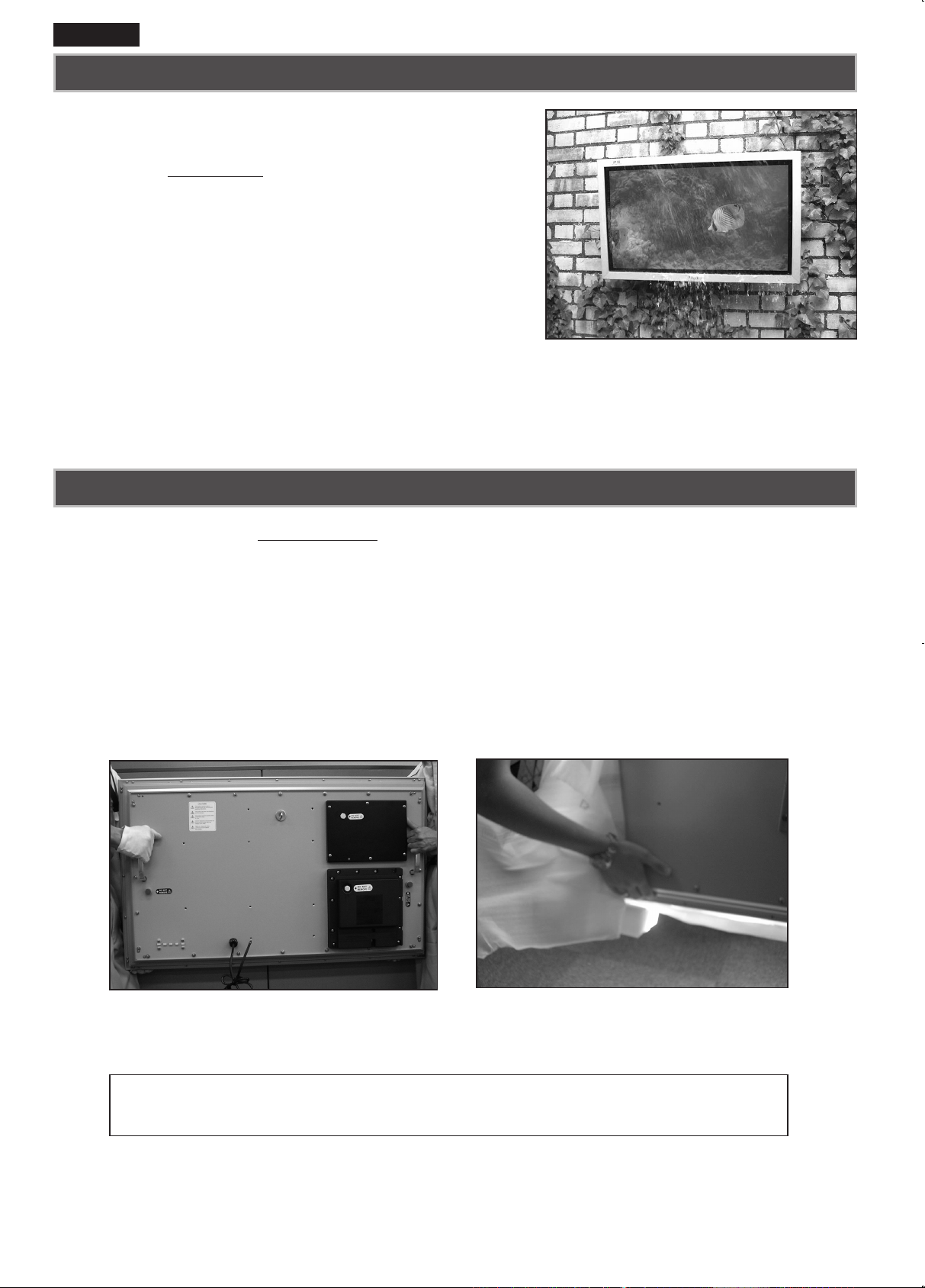
To All Installers,
This monitor is sealed to IP66 standard. The integrity of
the enclosure MUST NOT be tampered with or breached.
The following guide lines highlight those areas of the
product that require particular care and attention in order
to ensure the integrity of the enclosure.
• We strongly advise that 2 ~ 4 PEOPLE handle the monitor when removing it from the carton.
Dropping or bumping the monitor during unpacking can result in damage to the sets integrity and
appearance.
• Please ensure carton top is facing upwards before removing monitor.
• Before removing monitor from carton, we recommend that the mounting bracket is attached rst to
avoid any damage during installation.
• Please ensure that both installers grip the monitor as shown in photos below.
To lift and maneuver the monitor, please use the handles provided and support from underside as
illustrated in picture.
IMPORTANT! !
REMOVAL FROM OUTER CARTON
Always use the handles to lift the set
ALWAYS SUPPORT THE MONITOR FROM UNDERNEATH
English
IT IS STRONGLY RECOMMENDED
TO HANDLE BY 2 ~ 4 PEOPLE.
Page 3
3
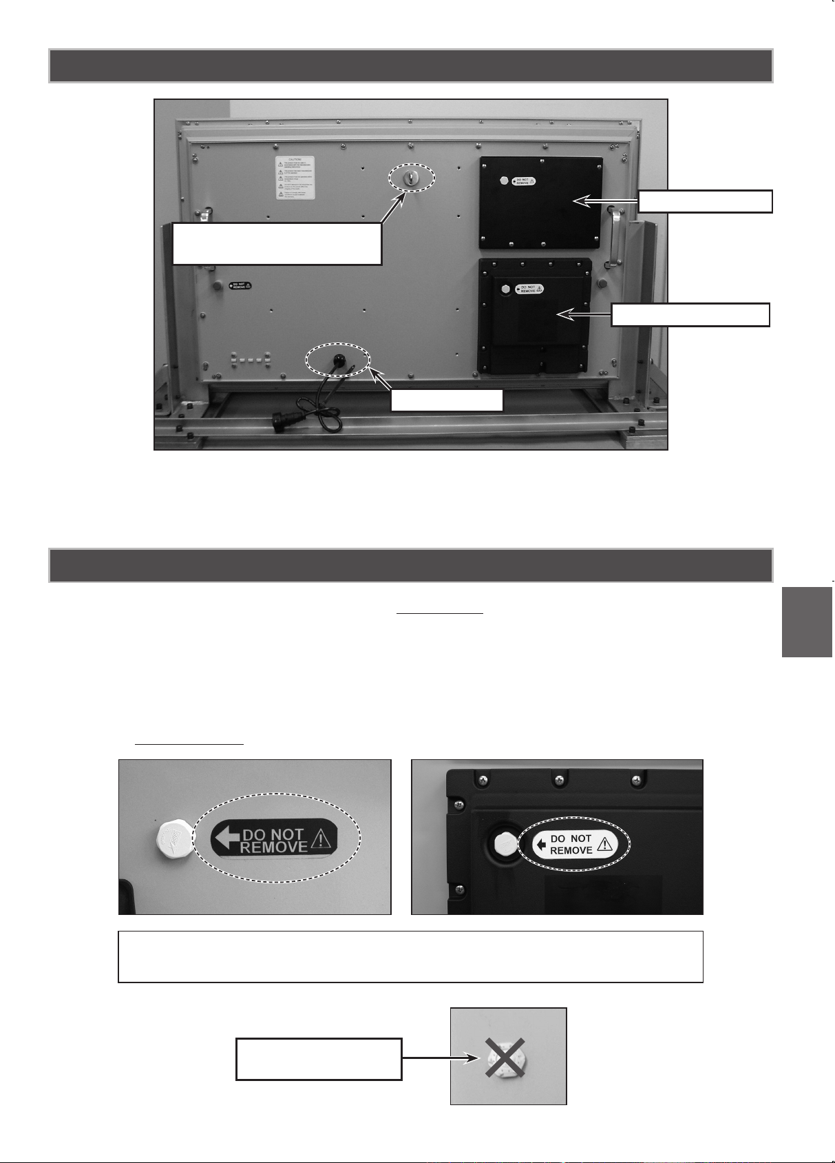
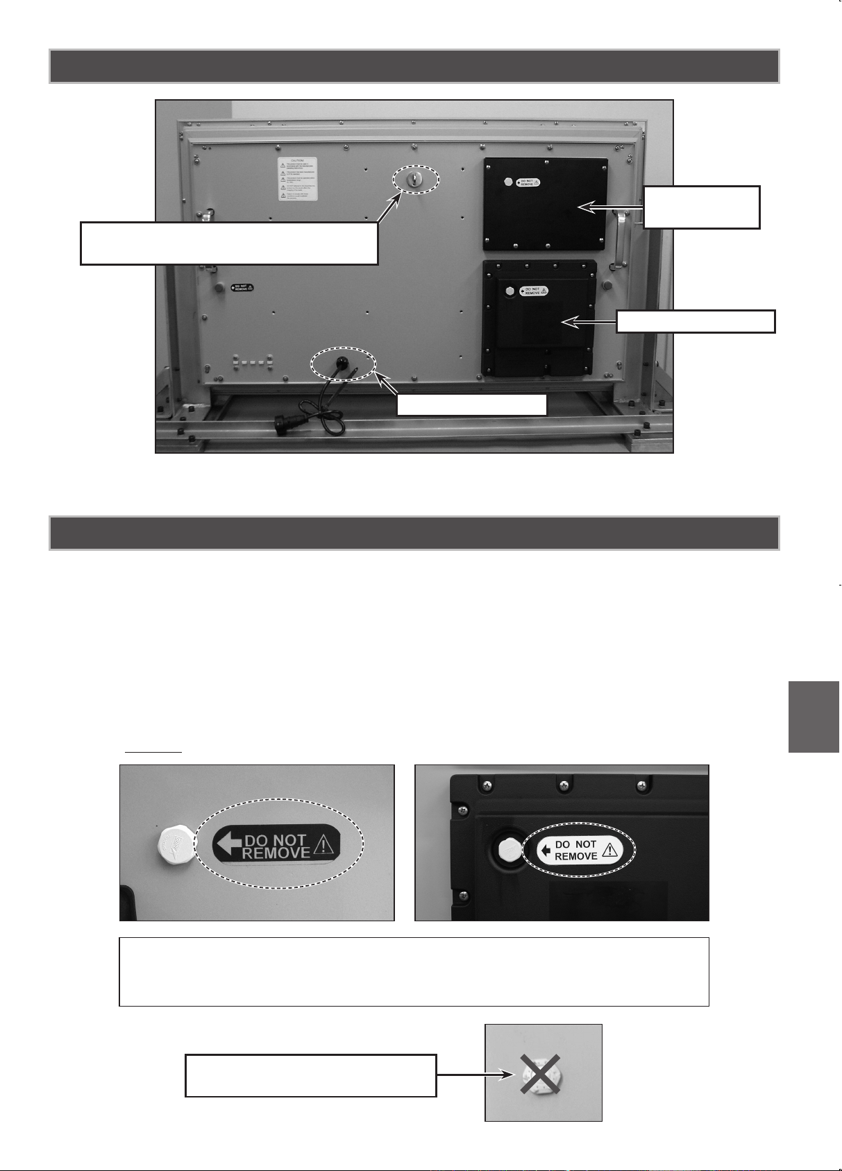
English
• There are labels to inform users that the vents MUST NOT be loosened or removed otherwise
the sealing of the set will be compromised. Adhesive applied to the vent threads provides added
seal security and a visual indication of tampering. In the event that this adhesive sealing is broken
when the set is returned, SANYO can not accept liability for the condition.
• Vent caps can be easily damaged. The set should always be lifted (DO NOT SLIDE) and always
make use of raised cushions under the aluminium frame if placed flat on rear side.
• The vents SHOULD NOT be covered or obstructed.
BACK OF MONITOR
WEATHERPROOF ENCLOSURE VENTILATION
Please note that caps are easily damaged.
Do not lay monitor with rear side down without proper protection underneath.
EXAMPLE OF VENT
CAP MISSING
SECURITY FIXING POINT
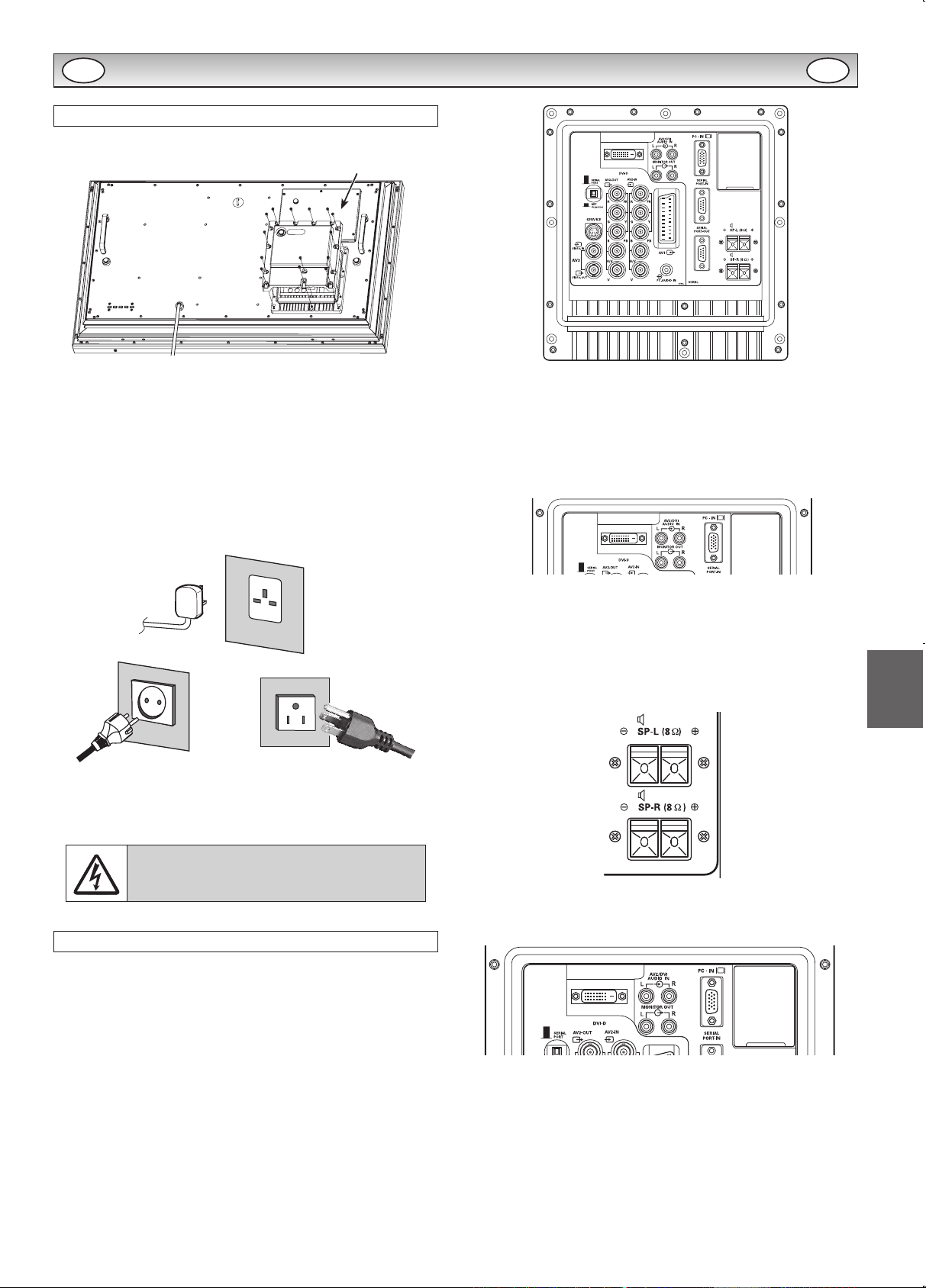
(42 inch model only)
MAINS LEAD
TERMINAL COVER
LD-NET COVER
* This photo is 42 inch model.
Page 4
4
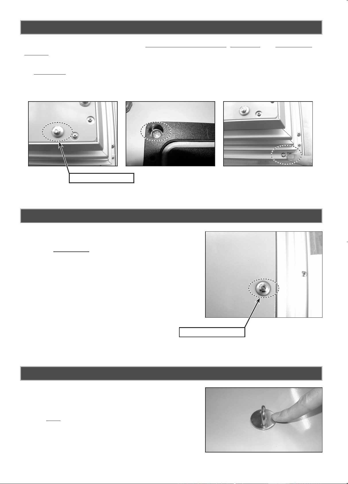
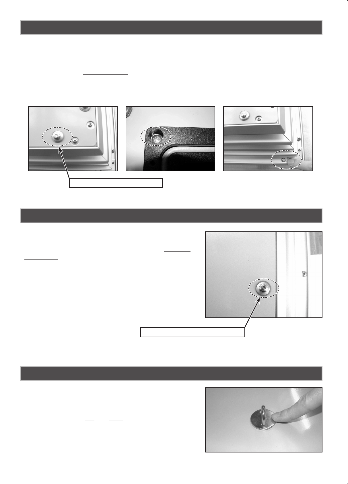
• Anti-tamper ink has been placed on the screws on the back plate, AV insert and outer back
cabinet.
• This is to identify if the screws have been removed. Any attempt to remove the anti-tamper ink will
be CLEARLY visible.
• In the event that the back plate is removed, the sealing of the set will be compromised, therefore,
SANYO can not accept liability for any related failure.
• All back plate xing screws utilise rubber sealing washers. This improves the air tight integrity of the xing and
therefore MUST NOT be removed.
• Only wall mount xing and terminal cover screws may
be removed by the installer. Under no circumstances
should non-SANYO screws be used as replacements.
ANTI-TAMPER INK
SCREWS
• A security xing point is provided on the back plate in
order to secure the monitor to the installation point with
a security device.
• This is NOT for lifting purposes. Lifting the monitor by
the security xing point will cause deformation of the
back plate, resulting in possible breakdown of the weatherproof seal.
SECURITY FIXING POINT (42 inch model only)
ANTI-TAMPER INK
RUBBER WASHER
Page 5
5
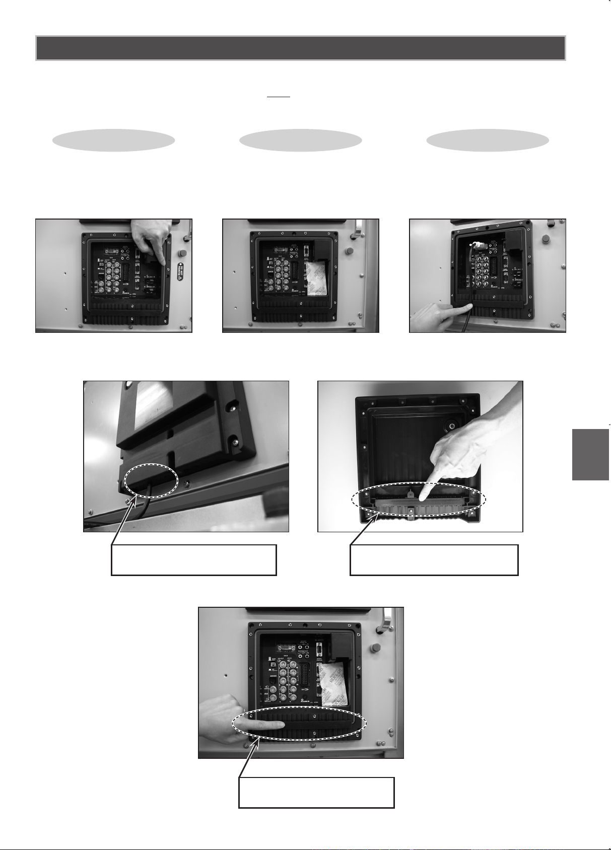
English
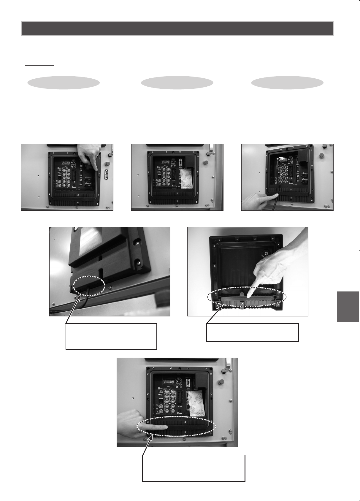
• After cable installation PLEASE ensure all seals are correctly tted as shown below prior to retting the terminal cover and rear A.V.cover. ALL xing screws must be replaced and tightened.
REAR A.V.SHIELD COVER/TERMINAL COVER
Check point
1
Check point
2
Check point
3
Check gasket is in place
inside the cover. Gasket
is important to seal cable
area.
Don’t remove silica gel
from terminal and LD Net
area.
Cables must t in the
shape of the recess of
the terminal base.
GASKET IN THE TERMINAL
COVER
MAKE SURE CORD FITS IN
THE MOULD SHAPE
GASKET IN THE RECESS
OF THE TERMINAL BASE
Page 6

6
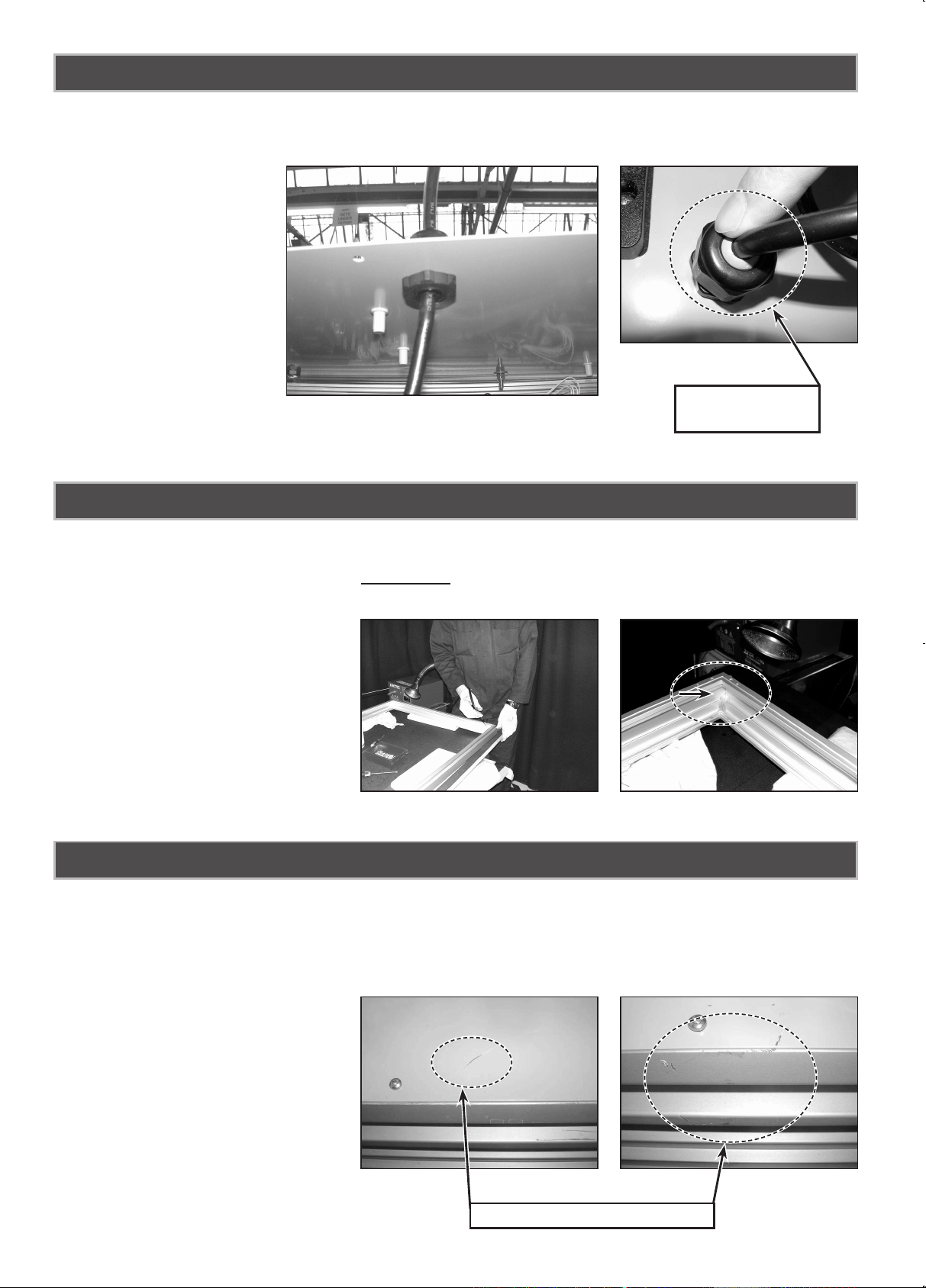
• The mains lead is secured to the back plate using a weatherproof cable gland.
Do not loosen the gland as this will impair the weatherproof sealing.
• The cabinet corners are sealed using a special adhesive to maximise the seal.
• Sets must be handled with EXTREME care to ensure that this seal is not damaged. Please take
particular care not to drop or bump the set during handling/installation.
MAINS LEAD
ADHESIVE TREATMENT
• The steel back plate is protected from corrosion using a polyester powder coating. Good care and
attention must be taken to prevent scratching the surface. Any uncoated metal will corrode poten-
tially affecting the integrity of the enclosure.
• Similarly the same care and attention applies to the aluminum enclosure which is anodised to pro-
tect it from corrosion.
COATING MATERIAL
VIEW INSIDE ENCLOSURE
RUBBER WASHER
CAUSE RUST!!
Page 7
7
English
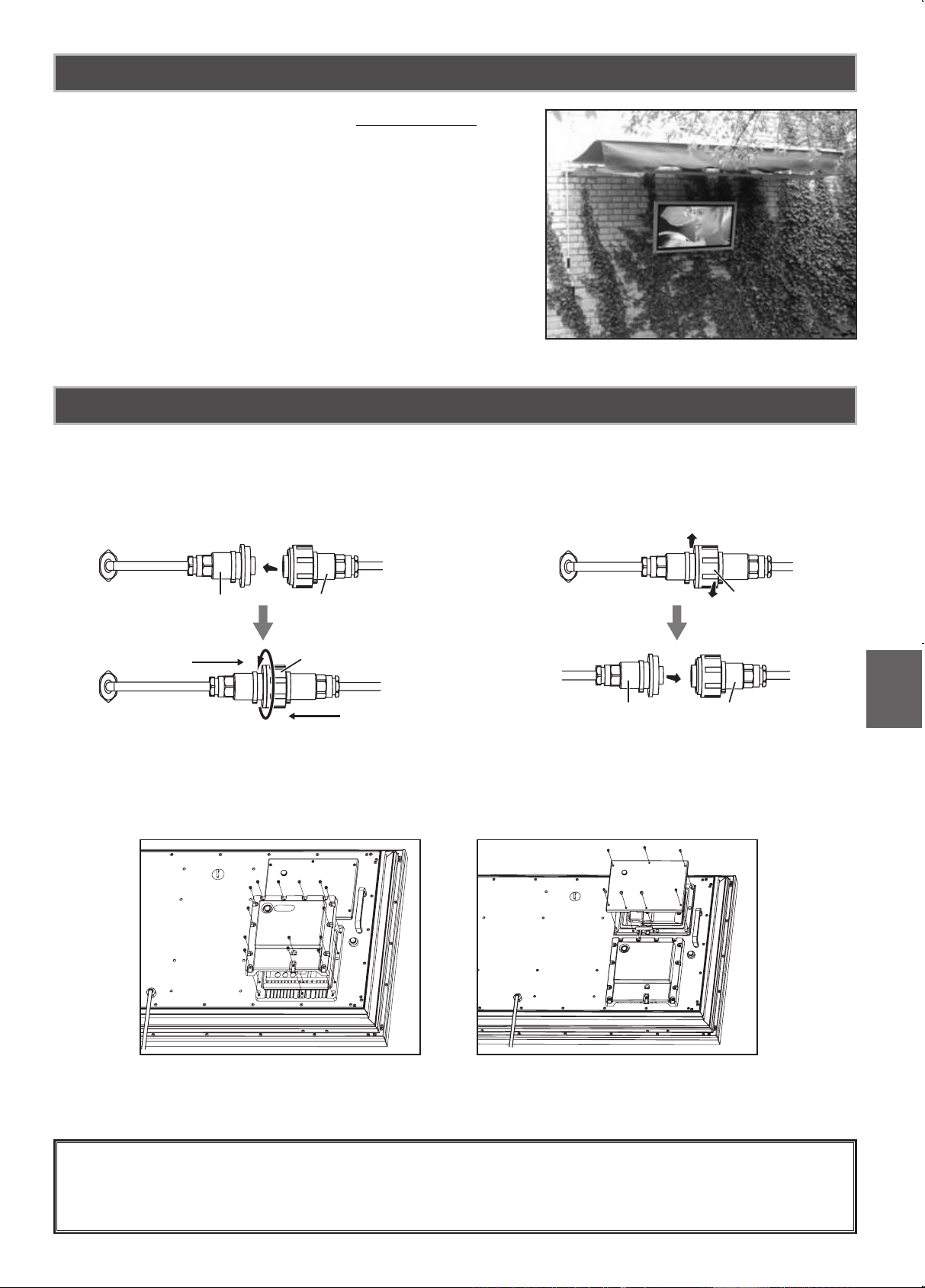
Thank you for your attention.
We hope our Weatherproof monitors are to your satisfaction.
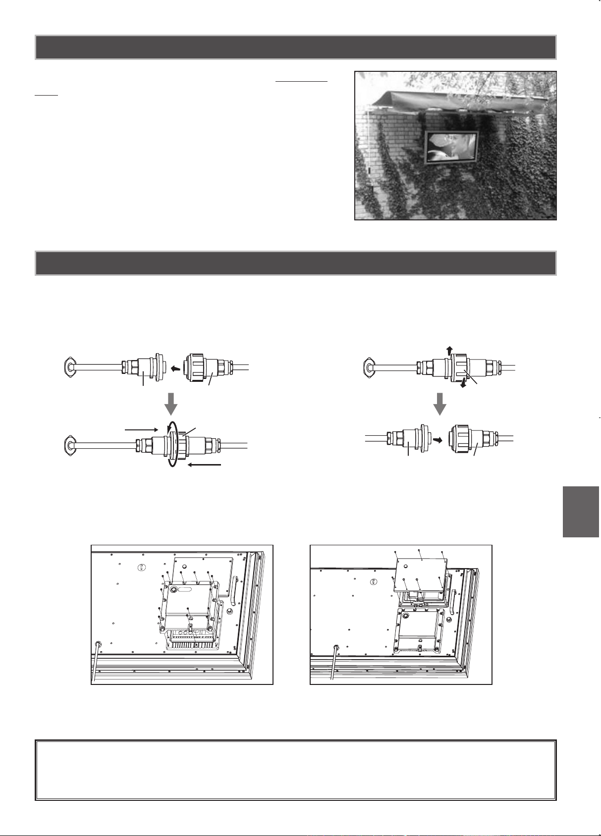
When the monitor installed outside, it SHOULD NOT set
in a position where the screen is subjected to direct sun
light.
If it can’t be done, please prepare adequate shading. Direct sun light can cause the screen surface temperature
to rise above the maximum operating range.
This causes a black shadow to appear on the screen,
which will disappear when the screen temperature returns
to within specication.
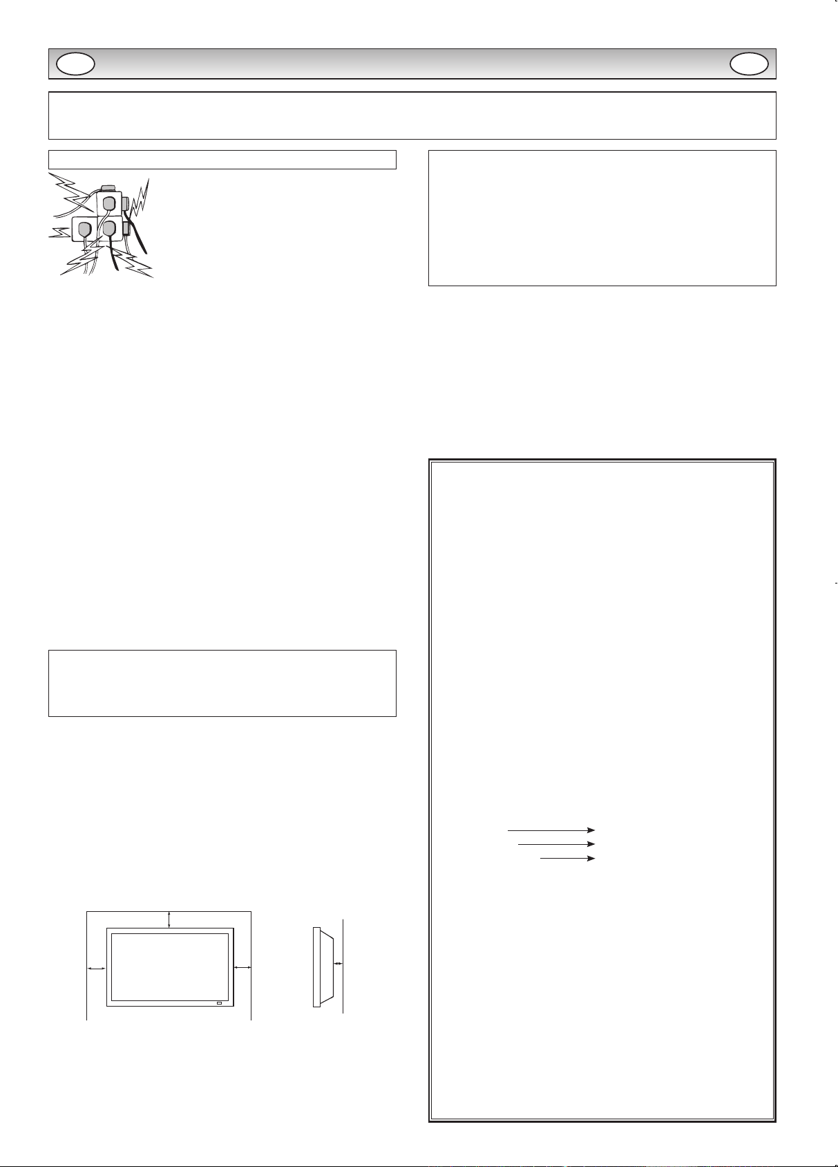
1. Connect the in-line waterproof AC cord, line up and push together connectors A & B so they are
tight and then twist C until A & B cannot be pulled apart. To disconnect unscrew C and pull connector A & B apart.
2. Remove the covers A for access to connect required cables. Re-position the covers and replace
screws.
If LD Net connection is required remove cover B and connect cable, then re-position cover B and
replace screws.
INSTALLING POSITION
WIRE ASSEMBLY
B
A
B
A
A
B
C
A
B
C
DO NOT REMOVE SILICA GEL SACHETS FROM INSIDE LD-NET TERMINAL COVER (B)
AND TERMINAL COVER (A).
To Connect To Disconnect
Page 8
8
CAUTION: Please read and retain for your safety. This unit has been designed and manufactured to assure your personal safety, but
improper use can result in potential electric shock or re hazards. In order not to defeat the safeguards incorporated in this monitor observe the
following basic rules for its installation, use and servicing.
Installation and Use
Do not allow anything to rest on the power
cord. Do not locate this LCD monitor where the
cord will be damaged by people walking on it.
Do not overload wall outlets and extension
cords as this can result in re or electric shock.
A suitable socket outlet must be provided near
to the monitor and shall be easily accessible.
Do not place this LCD monitor near any heat sources such as radia-
tors, heaters, stoves and other heat-generating products (including
ampliers).
Do not place your LCD monitor on an unstable stand, shelf or table.
Serious injury to an individual, and damage to the LCD monitor may
result if it should fall. Your sales person can recommend an approved
wall mounting kit. A special wall mounting kit is available for this
model.
This LCD monitor should be operated only from the type of power
source indicated on the monitor or as indicated in the Operating Instructions. If you are not sure of the type of power supply, consult your
sales person or your local power company.
For added protection it is strongly recommended that this LCD
monitor has its mains supplied via an approved earth fault protection
device.
WARNING: To prevent injury the LCD monitor must be securely
attached to the wall in accordance with the manufacturers installation
instructions.
IMPORTANT:
This product must be earthed.
This unit is not disconnected from the mains unless the mains lead
is unplugged. The installer must make sure that the waterproof inline
coupler is easily accessible.
(CE42LM6WP/CE42SR2/CE52LH2WP/CE52SR2 model only)
This monitor is tested to IP66 standard rating.
This monitor is not protected against temporary or continuous
immersion in liquid.
Do not use immediately after moving the LCD monitor from a low
temperature to a high temperature environment, as this causes condensation, which may result in re, electric shock, or other hazards.
Before cleaning, unplug the monitor from the wall socket.
Do not mount near an open ame source. Open ames must never
be used near this LCD monitor.
This LCD monitor should not be built in or enclosed in any way, heat
build up will reduce the life of the monitor.
This LCD monitor should have a minimum distance of 5cm away from
the wall and the monitor should have 10cm distance around the top
and sides.
Always mount using recommended and substantial xtures and t-
tings.
10cm
10cm
10cm
5cm
The rear nned section around the cabinet functions as a heat sink,
removing heat away from the monitor. The external surface of the
cabinet (nned area) must not be covered or the airow restricted in
anyway by enclosing the LCD monitor.
(CE42LM6WP/CE42SR2/CE52LH2WP/CE52SR2 model only)
The operating temperature range of this monitor is guaranteed
0°C ~ 40°C/32°F ~ 104°F. It is not recommended to install the
screen in direct sunlight without adequate shading, as this will
cause the temperature of the panel to rise above the maximum
specied. Doing so may cause a black shadow to appear on the
screen which will disappear when the screen temperature returns
to within the specication. This “of course” does not produce any
harmful effect on the lifetime of the monitor.
Do not apply liquid cleaners or aerosol cleaners directly onto the LCD
monitor. Use a damp cloth for cleaning.
ADDITIONAL FOR NORTH AMERICA AND CANADA:
This monitor must NOT be permanently mounted to the building
structure. It must be mounted in such a way that it can be removed
using basic tools.
The power supply cord must NOT be attached to the building surface.
The power supply cord must NOT be routed through walls, ceiling,
floors, or other similar openings in the building structure.
The power supply cord MUST be positioned so as to prevent physical
damage.
Important: (UK only)
THIS PRODUCT MUST BE EARTHED.
This equipment is tted with an approved mains lead and an
approved non rewireable UK mains plug. To change a fuse in this
type of plug proceed as follows:
1. Remove the fuse cover and fuse.
2. Fit a new fuse which should be a BS1362 13 Amp A.S.T.A. or
BSI approved type.
3. Ensure that the fuse cover is correctly retted.
If the fuse cover is lost or damaged the plug must NOT be used
but replaced with a serviceable plug.
If the tted plug is not suitable for your socket outlets, it should
be cut off and an appropriate plug tted in its place. If the mains
plug contains a fuse, this should have a rating of 13 Amp, ensure
the fuse cover is correctly tted. If a plug without a fuse is used,
the fuse at the distribution board should not be greater than 13
Amp.
Note: The severed plug must be destroyed to avoid a possible
shock hazard should it be inserted into a 13 Amp socket else-
where.
The wires in this mains lead are coloured in accordance with the
following code:
Blue Neutral
Brown Live
Green and Yellow Earth
1. The Blue wire must be connected to the terminal which is
marked with the letter “N” or coloured BLACK.
2. The Brown wire must be connected to the terminal with the
letter “L” or coloured RED.
3. The Green and Yellow wire must be connected to the termi-
nal which is marked with the letter “E” or coloured GREEN or
GREEN and YELLOW.
Before replacing the plug cover, make certain that the cord grip is
clamped over the sheath of the lead - not simply over the wires.
Do not attempt to bypass the safety purpose of the grounding
type plug.
THIS UNIT IS NOT DISCONNECTED FROM THE MAINS UNLESS THE MAINS LEAD IS UNPLUGGED.
THE INSTALLER MUST MAKE SURE THE MAINS LEAD IS
EASILY ACCESSIBLE.
SAFETY PRECAUTIONS
GB GB
Page 9
9
English
Servicing
Your monitor is fully transistorised and does not contain any user serviceable components.
You must not remove the rear cover of the monitor by yourself. The apparatus is working with high voltages and could damage
objects or even endanger people. Leave all required repair and service jobs to an authorised service technician. He will exclusively
use such spare parts that are complying with the same safety standards as applicable to the original parts. The use of original spare
parts can prevent fire, shock and other hazards.
Unplug the LCD monitor from the wall outlet and refer servicing to qualified service personnel under the following
conditions:
n If the power cord or plug is damaged.
n If liquid has been spilt in to the LCD monitor.
n If the LCD monitor has been dropped or the cabinet has been damaged.
n If the LCD monitor exhibits a distinct change in performance.
n If the LCD monitor does not operate normally by following the operating instructions.
n If the LCD monitor has been exposed to rain or water. (CE42LM6R /CE42LM6DPB /CE52LH2R model only)
Adjust only those controls that are covered in the operating instructions as improper adjustment of other controls may result in damage.
This will often require extensive work by a qualied technician to restore the monitor to normal operation.
Federal Communications Commission Notice
This equipment has been tested and found to comply with the limits for a Class A digital device, pursuant to Part 15 of FCC Rules. These limits
are designed to provide reasonable protection against harmful interference when the equipment is operated in a commercial environment. This
equipment generates, uses, and can radiate radio frequency energy and, if not installed and used in accordance with the instruction manual,
may cause harmful interference to radio communications. Operation of this equipment in a residential area is likely to cause harmful interfer-
ence in which case the user will be required to correct the interference at his own expense.
Do not make any changes or modications to the equipment unless otherwise specied in the instructions. If such changes or modications
should be made, you could be required to stop operation of the equipment.
Canadian Radio Interference Regulations
This Class A digital apparatus meets all requirements of the Canadian ICES-003.
WARNING
This is a Class A product. In a domestic environment this product may cause radio interference in which case the user may be required to take
adequate measures.
Important recycling information.
Your SANYO product is designed and manufactured with high quality materials and components
which can be recycled and reused.
This symbol means that electrical and electronic equipment, at their end-of-life, should be dis-
posed of separately.
In the European Union there are separate collection systems for used electrical and electronic
products.
Please help us to conserve the environment we live in!
Note: This symbol mark and recycle system are applied only to EU countries are not applied to
other countries of the world.
SERVICING
GB GB
Page 10
10
AC Power Cord Requirement
The AC Power Cord supplied with this LCD monitor meets the requirement for use in the country in which you
purchase it.
AC Power Cord for the United States and Canada:
AC Power Cord used in the United States and Canada is listed by the Underwriters Laboratories (UL) and certied
by the Canadian Standard Association (CSA).
AC Power Cord has a grounding-type AC line plug. This is a safety feature to make sure that the plug will t into the power outlet.
Do not try to defeat this safety feature. Should you be unable to insert the plug into the outlet, contact your electrician.
THE SOCKET-OUTLET SHOULD BE INSTALLED NEAR THE EQUIPMENT AND EASILY ACCESSIBLE
End-User License
The product (meaning the equipment or appliance to which this documentation relates) incorporates Software (the software applications, utilities and modules embedded within the Product) which is owned by Sanyo or its licensors. Before using the product, please read the End-User
License Conditions detailed below. If you do not agree to the terms and conditions of the End-User License, Please do not proceed to use the
Product- repack the Product unused and return it to your supplier together with proof of purchase for a full refund. By using the product, you
agree to be bound by the terms and conditions of the End-User License.
License Grant, Conditions and restrictions
1. Sanyo grants you a non-exclusive, world-wide (subject to export controls), non-transferable (except as permitted by 2 below), royalty-free
license to use the Software upon and with the Product.
2. You may not transfer any of your license rights in the Software without the prior written consent of SANYO and if consent is provided then
the Software shall only be transferred in conjunction with the transfer of the Product AND provided that the transferee has read and agreed
to accept the terms and conditions of this license.
3. You must ensure that the copyright, trademark and other protective notices contained in the Software are maintained and not altered or
removed.
4. The Software provided hereunder is copyrighted and licensed (not sold). SANYO especially does not transfer title or and ownership rights
in the Software to you. The Software provided hereunder may contain or be derived from portions of materials provided to SANYO under
license by a third party supplier.
5. Except as expressly permitted by statute you may not;
¡use the Software in conjunction with any other computer hardware other than the product;
¡copy all or part of the Software;
¡incorporate all (or any of) the Software into other programs developed by (or on behalf of) you and/or used by you;
¡reverse-engineer, decompile or disassemble the Software;
¡make the Software (or any part of it) available, or permit its redistribution, for use with any computer hardware other than the Product; or
rent, lease, gift, loan, sell, distribute or transfer possession of the whole or any part of the Software.
Termination
This license is effective until terminated. This license will terminate automatically without notice if you fail to comply with any of its provisions.
Disclaimer
1. The Software is(to the extent permitted by law) supplied “as is” and SANYO and its suppliers expressly exclude all warranties, express or
implied, including (but not limited to) warranties of satisfactory quality, tness for purpose and non-infringement (save to the extent that the
same are not capable of exclusion at law).
2. In no circumstances will SANYO be liable for any direct, indirect, consequential, or incidental damage (including loss of prots, business
interruption, loss of data or the cost of procurement of substitute goods, technology or services) arising out of the use or the inability to use
the Software (save to the extent that such liability is not capable of exclusion at law).
General
1. This End-User License will be governed by laws of England and the User may only bring claims in the English Courts and SANYO shall be
entitled to bring a claim in the courts of any jurisdiction.
2. This End-User License is governed by the laws of the State of California. The End-User and Sanyo agree that any action to enforce or
interpret the terms of this End-User License shall be brought only in the appropriate state or federal court located in Los Angeles County,
California.The End-User and Sanyo hereby submit to the exclusive jurisdiction and venue of such court.
3. The above terms and conditions supersede any prior agreement, oral or written, between you and SANYO relating to the Software.
SERVICING
GROUND
GB GB
Page 11
11
English
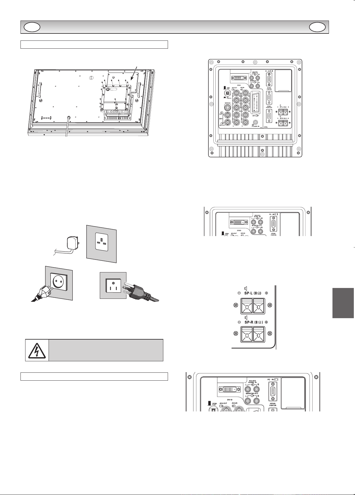
Step: 1 Mains Connection
n Connect the display unit to VGA, BNC and Scart con-
nector as required.
1. Connect the in-line power connector to the Mains Inlet as shown
above.
2. Connect the power cord of the LCD monitor to a suitable wall
outlet.
✐ As this product does not have a mains On/Off switch, please
ensure your mains plug is easily accessible.
✐ The LCD monitor is prepared for a mains voltage AC100 ~ 240V,
50Hz/60Hz. To completely switch off the mains, or when the
display unit is not to be used for an extended period of time, it is
advisable to disconnect the power cord from the power outlet.
✐ Please use the correct mains lead supplied with the set for your
area.
3. Warning: To prevent injury, the unit must be securely attached to
the wall in accordance with the installation instructions.
WARNING! High voltages are used in the
operation of this set. Refer service to qualied
service personnel.
Step: 2 Connections
n INPUT selection
To switch either AV1, RGB, AV2, AV3, PC, DVI or Network by pressing
the INPUT button on your remote control repeatedly.
1. AV1
SCART connection/CVBS/RGB/S-VIDEO.
2. RGB
TTL input (5V RGB signals) into SCART terminal.
3. Y, Pb, Pr/RGBHV connection (AV2)
Choose Y, Pb, Pr or RGB H/V connection by selecting AV2 Setting
in Set up menu (refer to the INSTRUCTION MANUAL on page 10).
You can connect your DVD player to the Y, Pb, Pr terminals instead
of using a scart lead. This can support high denition in analogue
component form. RGB H/V can be used as a PC input via the BNC
terminals. Both options support a large range of resolutions (refer
to the INSTRUCTION MANUAL on page 17). AV2-OUT can be
used to output the incoming AV2 signal to the other monitor.
4. AV3
Composite (CVBS) signal input.
AV3-OUT can be used to output the incoming AV3 signal to the
other monitor.
5. DVI-D (Digital Video Interface)
DVI-D supports a large range of resolutions as shown in the INSTRUCTION MANUAL on page 17.
6. PC connection
PC input (PC-IN D-SUB). This input supports a large range of resolutions as shown in the INSTRUCTION MANUAL page 17. Audio
can be connected via the 3.5mm PC-AUDIO IN.
7. External Speaker
Output the audio signal from AV1, AV2, AV3, PC and DVI.
The speaker impedance is 8 ohms.
8. AV2 / DVI AUDIO IN
Connect the audio output (stereo) from a computer or video equip-
ment connected AV2 or DVI.
9. Monitor Audio OUT
This terminals output xed level from AUDIO IN.
10. RS232C IN/OUT
When the monitor is controlled by a computer, connect to this jack
with serial control cable.
You can connect to another monitor with RS232C OUT.
When you connect PC with RS232C, select “ON” at Network
standby in Installation mode.
If it is selected “OFF”, RS232C terminals do not functional. Also
select push button to “SERIAL POART”.
INSTALLATION
AC Mains Outlet
* This gure is 42 inch model.
LD-Net
GB GB
Page 12
12
Input
To switch input source from AV1, RGB, AV2, AV3,
PC, DVI or Network mode.
Standby
To switch the monitor on and off. Also, refer to the
INSTRUCTION MANUAL on page 8.
Menu
To enter and exit the main menu, and sub menu.
Wide
To select the screen mode Full, Full All, Zoom
16: 9, Title in 16:9, Zoom 14:9, Title in 14:9,
Normal or Natural wide.
Refer to the INSTRUCTION MANUAL on page 12.
Recall
To display input selection information and the Time
set.
You can also select colour systems in AV1/AV3
mode as follows: AUTO \ PAL \ SECAM \
NTSC \ NTSC4.43 \ PAL M \ PAL N.
Auto PC
It can also be automatically adjusted in PC mode
by pressing this button for twice .
Back
Used to return to the previous menu.
Up and Down
To select the next or previous item.
Sound Mute
To mute the sound from the speakers.
The sound changes as follows: Normal volume [\
Mute.
Bass Expander
To get an emphasised bass sound ON or OFF.
TXT/TV
To select Teletext mode.
Main/Sub Picture Swap
To swap Main and Sub picture.
ON/OFF
To switch OFF \ PIP(1) \ PIP(2) \ POP mode
in turn.
Refer to the INSTRUCTION MANUAL on page 13.
Level Up/Down
To adjust the sound volume level or enter sub
menus.
F/OK
To conrm the initial setting in the menu.
Picture mode selector
Press the 9 button repeatedly to select the following picture mode.
Personal - Personal preference mode.
Standard - Normal viewing mode.
Dynamic - Suitable for brightly lit rooms.
Soft - Low contrast setting
Eco - Suitable for dimly lit rooms and gives a
cinema-like effect.
Freeze
To switch picture still on or off.
Green
Press this button for more than 5 seconds, installa-
tion mode will appear.
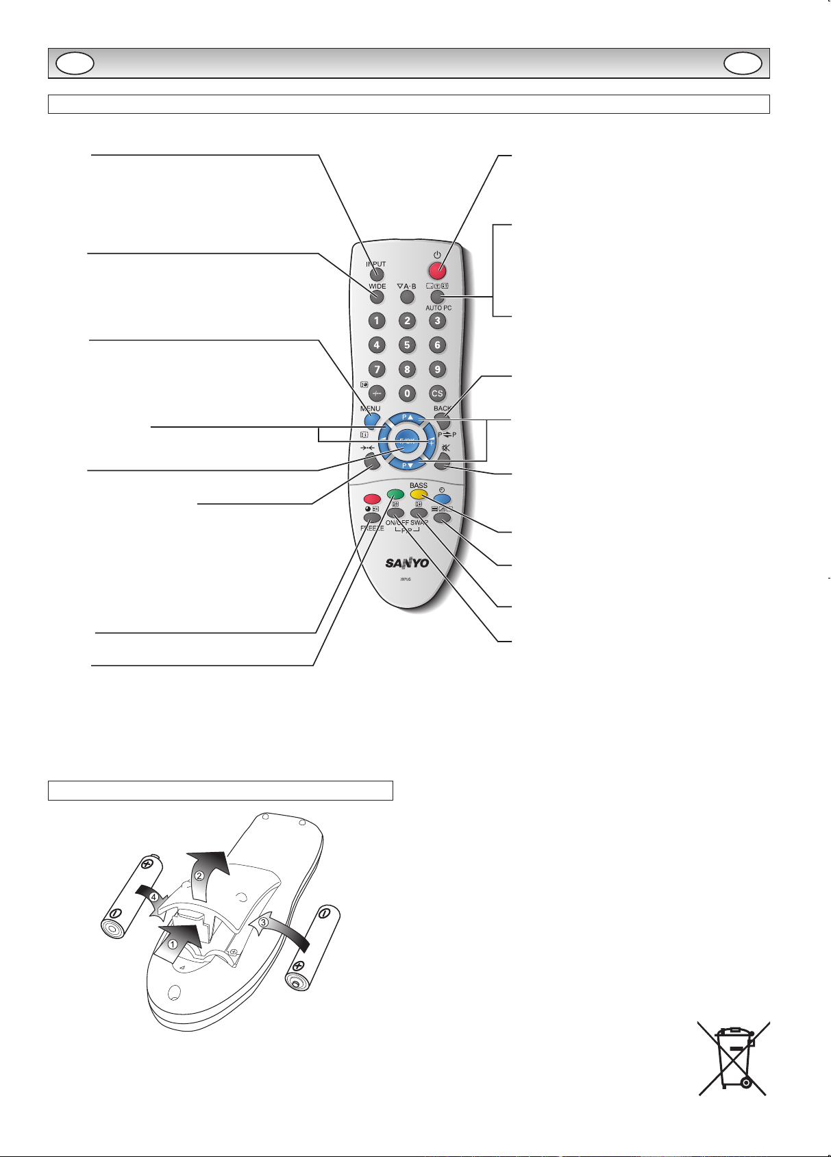
Remote control
Remote control battery installation
Install two “AA” 1.5 volt batteries so that the “+” and “–” marks on the
batteries match the “+” and “–” marks inside the unit into the remote
control handset.
FOR EU USERS
The symbol mark and recycling systems described below apply to EU
countries and do not apply to countries in other areas of the world.
Your SANYO product is designed and manufactured with high quality
materials and components which can be recycled and/or reused.
The symbol mark means that electrical and electronic equipment,
batteries and accumulators, at their end-of-life, should be disposed of
separately from your household waste.
Note:
If a chemical symbol is printed beneath the symbol mark, this chemical symbol means that the battery or accumulator contains a heavy
metal at a certain concentration. This will be indicated as follows: Hg:
mercury, Cd: cadmium, Pb: lead
In the European Union there are separate collection systems for used
electrical and electronic equipment, batteries and accumulators.
Please, dispose of them correctly at your local community waste collection/recycling centre.
Please, help us to conserve the environment we live in!
INSTALLATION
GB GB
Page 13
13
English
INSTALLATION
Controls and Menus
q
w
q
The LCD display has a Standby light to show there is power.
Switching into/from standby mode
The Standby mode is used for switching the LCD monitor off for short
periods of time. In standby mode the monitor is switched off but is still
receiving mains power.
¡To turn the monitor into standby mode, press the 4 button.
The blue power indicator illuminates more brightly.
¡To turn the monitor ON from standby mode, press the 4 button
again.
If you nd the power indicator ashing, disconnect
power cord from the power outlet and contact our
Service desk.
This warning is a sign to let you know that the
power protection function of this TV set is now
operating.
w
Control buttons (bottom corner of back cover)
Menu button: Used to display or cancel main menu.
Input/d button: Switch between AV1, RGB, AV2, AV3, PC , DVI
or Network mode. It is also used to provide sub
menu selection from the Main Menu.
1 or 2 buttons: provide up and down adjustments.
4 button: To switch to standby mode (to switch off completely
disconnect the monitor from the power supply).
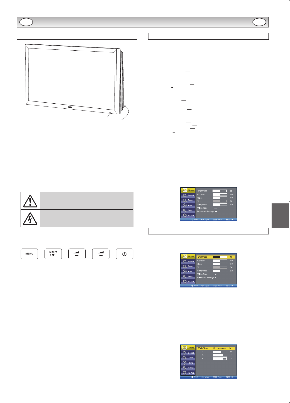
Menu Operation
Many of your monitors functions are controlled through the menu
function, using the remote control.
MENU
Picture
Brightness
Contrast
Color
Tint (only if NTSC equipment is detected)
Sharpness
White Tone
White Tone / R / G / B
Advanced Setting
DCDi / ACC/ACM / CCS / DNR / MPEG NR / Film Mode
Sound
Treble
Bass
Balance
Bass Expander
On / Off
Time
Setup
PC Adj.
Current Time
Schedule
Weekday
On Program
AV1 / RGB / AV2 / AV3 / PC / DVI / Network
Menu Setup
PIP / POP Setup
Initial Settings
Text Language
Tile Mode
AV2 Setting
Western / Eastern / Russian / Arabic / Farsi
Tile Mode Active / H/V_Sets / H/V Location / Bezel H/V Adjustment
RGBHV / YPbPr
Auto Adjust
H-Position
V-Position
Clock
Phase
Language / H/V-Position / Duration / Transparence
PIP/POP Mode / Main/Sub Source / PIP Position
Time
Action
Active
Power On / Power Off
On / Off
1 - 20
Current Weekday
Native Resolution
PC Power save
XGA / WXGA 1366x768
On / Off
During menu operation the bottom of the on screen display will show
which controls can be used for menu navigation.
Press the MENU button to enter the main menu. Whenever main
menu is accessed initially, PICTURE will be the default selection.
A sub menu is selected using the 5 or 6 button and pressing
the 1 or 2 button when the required sub menu is highlighted.
When you have nished you can press the BACK button to return to
the previous menu, press the MENU button to exit the menu operation.
Picture menu
1. Press the MENU button. PICTURE will be the default selection.
Press the 1 or 2 button to enter.
Set the picture settings for your “personal” preference.
2. Use the 5 or 6 button to select eg. Brightness and the 1 or
2 button to adjust levels.
n White Tone
May be used to adjust the color tone of the picture. Use the 5 or
6 button to select White Tone and press the 1 or 2 button
to enter the sub menu. You can select Personal, Cool, Standard or
Warm settings by using the 1 or 2 button. To adjust the color
tone of the picture by using the 5 or 6 button to select Red(R),
Green(G) or Blue(B) and the 1 or 2 button to adjust levels.
These settings will be stored in personal mode automatically.
GB GB
Page 14

14
Note à l’intention des installateurs,
Ce moniteur est conforme à la norme d’étanchéité IP66.
Le boîtier NE DOIT PAS être ouvert ni manipulé pour ne
pas affecter son intégrité.
Les consignes suivantes identient les aspects de l’appareil qui exigent un soin et une attention particuliers pour
assurer l’intégrité du boîtier.
• Il est fortement recommandé de vous faire aider par 2 ~ 4 PERSONNES pour extraire le moniteur
de son carton d’emballage. L’intégrité et l’apparence de l’appareil pourront être endommagées en
cas de chute ou de choc du moniteur pendant le déballage.
• Tournez la partie supérieure du carton vers le haut avant de sortir le moniteur.
• Il est recommandé de xer le support de montage avant de sortir le moniteur de son carton d’emballage pour éviter tout dommage pendant l’installation.
• Le moniteur doit être soulevé de la manière illustrée. Utilisez les poignées prévues à cet effet pour
soulever et manoeuvrer le moniteur. Saisissez le moniteur par sa partie inférieure de la manière
illustrée.
IMPORTANT! !
DEBALLER L’APPAREIL
Utilisez toujours les poignées pour soulever l’ensemble
PLACEZ TOUJOURS UNE MAIN SOUS LE MONITEUR.
Français
IL EST FORTEMENT RECOMMANDE
DE VOUS FAIRE AIDER PAR 2 ~ 4
PERSONNES POUR MANIPULER LE
MONITEUR.
Page 15
15
Français
• Les d’étiquettes d’avertissement informent les utilisateurs que les vis des orices de ventilation
ne doivent être ni desserrées ni déposées pour ne pas compromettre l’étanchéité de l’appareil.
L’adhésif enduit sur les lets des vis du système de ventilation renforce l’étanchéité et révèle toute
tentative d’effraction. En cas de retour éventuel de l’appareil, SANYO déclinera toute responsabilité
si ce joint adhésif est brisé.
• Les capuchons de ventilation sont fragiles. Veillez toujours à soulever l’appareil (ET NON A LE
FAIRE GLISSER) et à placer des coussins sous le cadre en aluminium si le moniteur doit être couché à plat sur sa partie arrière.
• Veillez à ne PAS couvrir ni obstruer les orices de ventilation.
PARTIE ARRIERE DU MONITEUR
VENTILATION DU BOITIER ETANCHE
Attention : les capuchons sont fragiles.
Ne posez pas le moniteur sur sa partie arrière sans protection adéquate préa-
lable.
CAPUCHON DE VENTILATION
MANQUANT
POINT DE FIXATION DE SECURITE
(uniquement le modèle à 42 pouces)
CABLE SECTEUR
COUVRE-BORNES
COUVERCLE
LD Net
* Cette photo représente le modèle à 42 pouces.
Page 16
16
• Les vis de la plaque de fond, de la prise AV et du boîtier extérieur sont enduites d’encre anti-
effraction.
• Ce système permet de vérier si les vis ont été retirées. Toute tentative de suppression de l’encre
anti-effraction sera CLAIREMENT visible.
• La dépose de la plaque de fond affectera l’étanchéité de l’appareil. SANYO décline toute respon-
sabilité en cas de panne liée à la dépose de cet élément.
• Toutes les vis de xation de la plaque de fond com-
portent des rondelles d’étanchéité en caoutchouc. Ces
rondelles améliorent l’intégrité des xations et NE DOIVENT PAS être déposées.
• L’installateur ne doit déposer que les vis de xation murale et du couvre-bornes. Ne remplacez jamais des vis
SANYO par des vis d’une autre marque.
ENCRE ANTI-EFFRACTION
VIS
• La plaque de fond comporte un point de xation de sécurité, conçu pour xer le moniteur au point d’installation
à l’aide d’un dispositif de sécurité.
• Ce point de xation NE doit PAS être utilisé pour soule-
ver l’appareil. Le non-respect de cette consigne entraî-
nera une déformation de la plaque de fond et la rupture
potentielle du joint d’étanchéité.
POINT DE FIXATION DE SECURITE (uniquement le modèle à 42 pouces)
ENCRE ANTI-EFFRACTION
RONDELLE EN CAOUTCHOUC
Page 17
17
Français
• Une fois le câble installé, VEUILLEZ vérier que tous les joints sont correctement positionnés
comme indiqué ci-dessous, avant de reposer le couvre-bornes et bouclier de protection A.V. arrière.
TOUTES les vis de xation doivent être remplacées et serrées.
BOUCLIER DE PROTECTION A.V. ARRIERE/COUVRE-BORNES
Point de contrôle
1
Point de contrôle
2
Point de contrôle
3
Vériez que le joint d’étan-
chéité est correctement positionné à l’intérieur du cou-
vercle. Ce joint est essentiel
pour étanchéier la zone des
câbles.
Ne retirez pas le gel de
silice de la zone des bor-
nes/LD Net.
Adaptez les câbles dans
le renfoncement de la
plaque à bornes.
JOINT D’ETANCHEITE DANS
LE RENFONCEMENT DE LA
PLAQUE A BORNES.
JOINT D’ETANCHEITE DU
COUVRE-BORNES
ASSUREZ-VOUS QUE LE
CABLE EST INTRODUIT
DANS LE GUIDE MOULE.
Page 18
18
• Le câble secteur est xé à la plaque de fond par le biais d’un presse-étoupe étanche. Veillez à ne
pas desserrer le presse-étoupe pour ne pas affecter le joint d’étanchéité
• Les angles du boîtier sont étanchéiés à l’aide d’un adhésif spécial.
• Manipulez le téléviseur avec un soin EXTREME an de ne pas endommager ce joint adhésif.
Veillez notamment à ne pas cogner/laisser tomber l’appareil pendant la manipulation/l’installation.
• Un revêtement de poudre polyester protège la plaque de fond en acier contre la corrosion. Evitez
de rayer sa surface. Toute partie métallique non protégée sera exposée à un risque de corrosion
susceptible d’affecter l’intégrité du boîtier.
• Ces mesures de précaution s’appliquent également au boîtier en aluminium anodisé.
CABLE SECTEUR
TRAITEMENT ADHESIF
PRODUIT DE REVETEMENT
VUE INTERIEURE DU BOITIER
RONDELLE EN
CAOUTCHOUC
PROVOQUE LA ROUILLE!!
Page 19
19
Français
Nous vous remercions de votre attention.
Nous espérons que nos moniteurs étanches vous apporteront toute satisfaction.
POSITION D’INSTALLATION
Lorsque le moniteur est installé à l’extérieur, il NE DOIT
PAS être placé à une position où l’écran serait exposé
aux rayons directs du soleil.
Si une telle position n’est pas disponible, préparez un
dispositif de pare-soleil adéquat.
Les rayons directs du soleil peuvent faire s’élever la température de la surface de l’écran au-delà de la plage de
fonctionnement maximum.
Ceci fait apparaître une ombre noire sur l’écran, qui disparaîtra lorsque la température sera revenue dans les
limites spéciées.
1. Connectez le cordon secteur étanche en ligne, alignez et poussez ensemble les connecteurs A et
B de manière qu’ils soient bien fermes, puis tordez C jusqu’à ce que A et B ne puissent pas être
séparés. Pour déconnecter, dévissez C et séparez les connecteurs A et B en tirant.
2. Retirez les couvercles A d’accès pour connecter les câbles nécessaires. Remettez les couver-
cles et les vis en place.
Si la connexion LD Net est nécessaire, retirez le couvercle B et connectez le câble, puis remettez
le couvercle B et les vis en place.
MONTAGE DES FILS
A
B
C
A
B
C
NE RETIREZ PAS LES SACHETS DE GEL DE SILICE DE L’INTÉRIEUR DU COUVREBORNES LD-NET (B) ET DU COUVRE-BORNES (A).
Pour connecter Pour déconnecter
B
A
B
A
Page 20
20
CONSIGNES DE SÉCURITÉ
ATTENTION: Pour votre sécurité, lisez attentivement ce qui suit. Ce moniteur a été conçu et fabriqué pour garantir votre sécurité per-
sonnelle, mais peut poser un risque de choc électrique ou d’incendie en cas d’utilisation incorrecte. An de faciliter le bon fonctionnement des
dispositifs de sécurité intégrés, veuillez observer les règles de base suivantes, relatives à l’installation, l’utilisation et l’entretien de votre moniteur.
Installation et utilisation
Ne poser aucun objet sur le cordon d’alimentation. Ce moniteur LCD ne doit pas être placé à
un endroit où quelqu’un pourrait marcher sur le
cordon d’alimentation et l’endommager.
Pour éviter les risques d’incendie ou d’électro-
cution, ne pas surcharger les prises de courant
et les rallonges.
Une prise de courant appropriée doit se trouver à proximité de l’écran
et être facilement accessible.
Ne pas placer ce moniteur LCD près de sources de chaleur comme
des radiateurs, appareils de chauffage, cuisinières et autres appareils
produisant de la chaleur (y compris les amplicateurs).
Ne pas placer ce moniteur LCD sur un socle, une étagère ou une
table instable. Toute chute pourrait causer de graves blessures à une
personne et endommager le moniteur LCD. Le vendeur peut recommander un kit approuvé de xation murale. Un kit spécial xation
murale existe pour ce modèle.
Ce moniteur LCD doit être exclusivement branché au type d’alimen-
tation indiqué sur l’écran ou dans le mode d’emploi. En cas de doute
concernant le type d’alimentation, consulter le vendeur de l’écran ou
la compagnie d’électricité locale.
Pour une sécurité accrue, il est vivement conseillé d’utiliser un dispositif de protection de terre approuvé avec ce moniteur LCD.
AVERTISSEMENT: Pour éviter tout risque de blessure, ce moni-
teur LCD doit être solidement xé au mur conformément aux instruc-
tions d’installation fournies par le fabricant.
IMPORTANT:
Ce produit doit être mis à la terre.
Cet appareil est mis hors tension uniquement lorsque le câble secteur
est débranché. L’installateur doit s’assurer que le coupleur réseau
imperméable est facile d’accès.
(Modèles CE42LM6WP/CE42SR2/CE52LH2WP/CE52SR2 uniquement)
Cet écran respecte la norme IP66.
Il n’est pas protégé contre l’immersion provisoire ou continue dans
un liquide.
Pour empêcher toute condensation et éviter les risques d’incendie,
d’électrocution et autres, ne pas utiliser le moniteur LCD juste après
un déplacement résultant en une importante différence de température. Avant le nettoyage, débrancher le moniteur de la prise murale.
Ne pas installer l’écran près d’une source de amme nue. Ne jamais
utiliser de ammes nues près du moniteur LCD.
Ce moniteur LCD ne doit pas être intégré, ni encastré de quelque
façon que ce soit car l’accumulation de chaleur en réduirait la durée
de vie.
Prévoir un espace de 5 cm entre le moniteur LCD et le mur et de 10
cm en haut et sur les côtés. Toujours installer le moniteur LCD à l’aide
d’accessoires recommandés et solides.
10cm
10cm
10cm
5cm
La partie arrière empennée autour de l’armoire sert de dissipateur
thermique pour évacuer la chaleur provenant du moniteur. Ne pas
couvrir la surface externe de l’armoire (partie empennée), ni restreindre le ux d’air de quelque façon que ce soit en encastrant le moni-
teur LCD.
(Modèles CE42LM6WP/CE42SR2/CE52LH2WP/CE52SR2 uniquement)
La plage de températures de fonctionnement de ce moniteur est
garantie entre 0°C ~ 40°C/32°F ~ 104°F. Il est déconseillé d’exposer l’écran à la lumière directe du soleil sans ombre appropriée,
car la température du panneau dépassera alors le seuil maximal
précisé et une ombre noire apparaîtra sur l’écran, puis disparaitra
lorsque la température de l’écran aura baissé et sera de nouveau
conforme aux spécications. Cela ne produit “naturellement”
aucun effet néfaste sur la durée de vie du moniteur.
Ne pas appliquer de nettoyants liquides, ni d’aérosols nettoyants
directement sur le moniteur LCD. Utiliser un chiffon humide.
CONSIGNES SUPPLÉMENTAIRES POUR L’AMÉRIQUE DU
NORD ET LE CANADA:
Ce moniteur ne doit pas être xé en permanence à un bâtiment. Il doit
être installé de façon à être démonté à l’aide d’outils de base.
Le cordon d’alimentation ne doit PAS être attaché à la surface du bâtiment, et ne doit PAS être acheminé à travers des murs, plafonds, sols
ou autres ouvertures similaires du bâtiment.
Le cordon d’alimentation DOIT être positionné de manière à éviter
tout dommage physique.
Important: (Le Royaume-Uni seulement)
CE PRODUIT DOIT ÊTRE BRANCHÉ SUR UNE PRISE DE TERRE.
Ce moniteur est équipé d’un cordon secteur homologué et d’une
che secteur britannique non démontable. Pour remplacer le
fusible de ce type de che, procédez comme suit:
1. Retirez le cache du fusible et le fusible.
2. Installez un nouveau fusible, de type BS1362 13 A., A.S.T.A
ou BSI.
3. Veillez à ce que le cache du fusible soit remis correctement en
place.
Si le cache du fusible est perdu ou endommagé, la che NE doit
PAS être utilisée mais être remplacée par une che en bon état.
Si la che installée ne correspond pas à votre prise de courant,
coupez-la et remplacez-la par une prise adaptée. Si la che
secteur comporte un fusible, utilisez un fusible de 13 A et veillez
à ce que le cache du fusible soit correctement installé. Si la che
utilisée ne nécessite pas de fusible, le fusible du panneau de
distribution ne devra pas excéder 13 A.
Remarque: Le fusible endommagé doit être éliminé pour préve-
nir tout risque de choc électrique en cas d’utilisation accidentelle
sur une autre prise 13 A.
Les ls du cordon secteur correspondent au code de couleurs
suivant:
Bleu Neutre
Marron Sous tension
Vert/Jaune Terre
1. Le l Bleu doit être raccordé à la borne “N” ou de couleur
NOIRE.
2. Le l Marron doit être raccordé à la borne “L” ou de couleur
ROUGE.
3. Le l Vert/Jaune doit être raccordé à la borne “E” ou de cou-
leur VERTE ou VERTE et JAUNE.
Avant de reposer le couvercle de la che, assurez-vous que le
serre-ls est placé sur la gaine du cordon et non pas simplement
sur les ls.
N’essayez pas de contourner le système de sécurité de la che
de raccordement à la terre.
LE MONITEUR RESTERA SOUS TENSION TANT QUE L’ALIMENTATION SECTEUR N’EST PAS DÉBRANCHÉE.
IL INCOMBE A L’INSTALLATEUR DE S’ASSURER QUE LE
CORDON D’ALIMENTATION SECTEUR EST FACILEMENT
ACCESSIBLE.
F F
Page 21
21
Français
RÉPARATION
Réparation
Votre moniteur LCD est entièrement transistorisé et ne contient aucun composant réparable.
Vous ne devez pas enlever le capot arrière du moniteur par vos propres moyens. L’appareil fonctionne sous haute tension et vous
risqueriez d’endommager ses composants ou de provoquer un accident. Confiez les réparations nécessaires à un technicien agréé.
Celui-ci utilisera exclusivement des pièces de rechange conformes aux normes de sécurité des pièces d’origine. L’utilisation de
pièces de rechange d’origine contribue à prévenir les risques d’incendie, de choc électrique, etc.
Débranchez le moniteur LCD de sa prise murale et faites appel à du personnel qualifié dans les cas suivants:
n Le câble d’alimentation ou la prise sont endommagés.
n Du liquide a été renversé sur le moniteur LCD.
n Le moniteur LCD est tombé ou le boîtier est endommagé.
n Dégradation des performances de votre moniteur LCD.
n Le moniteur LCD ne fonctionne pas normalement lorsque vous suivez les instructions données.
n Si l’écran LCD s’est trouvé exposé à la pluie ou à l’eau. (Modèles CE42LM6R/CE42LM6DPB/CE52LH2R uniquement)
Ne réglez que les commandes mentionnées dans le manuel d’utilisation. Tout réglage incorrect des autres commandes pourrait endommager
le moniteur et exiger l’intervention prolongée d’un technicien qualié.
Information importante sur le recyclage.
Votre produit Sanyo est conçu et fabriqué avec des matèriels et des composants de qualité
supérieure qui peuvent être recyclés et réutilisés.
Ce symbole signie que les équipements électriques et électroniques en n de vie doivent être
éliminés séparément des ordures ménagères.
Dans l’Union Européenne, il existe des systèmes sélectifs de collecte pour les produits élec-
triques et électroniques usagés.
Aidez-nous à conserver l’environnement dans lequel nous vivons !
Remarque: Ce symbôle et le système de recyclage ne concernent que les pays de l’Union
européenne et ne s’appliquent pas aux autres pays.
Avis de la commission fédérale des communications
Cet appareil a été testé et jugé conforme aux limites des appareils numériques de classe A, conformément à l’article 15 des règlements FCC.
Ces limites sont destinées à assurer une protection raisonnable contre les interférences nuisibles lorsque cet appareil est utilisé dans un environnement commercial. Cet appareil produit, utilise et peut émettre de l’énergie de fréquence radio, et s’il n’est pas installé et utilisé conformément au mode d’emploi, il pourra produire des interférences affectant négativement les communications radio. L’utilisation de cet appareil
dans une zone résidentielle risque de causer des interférences nuisibles, auquel cas l’utilisateur sera tenu de corriger les interférences à ses
propres frais. N’effectuez aucun changement ou modication de l’équipement qui ne soit pas spécié dans les instructions. Si vous effectuez
de tels changements ou modications, on pourra vous demander d’arrêter d’utiliser l’équipement.
Déclaration de Conformité d’Industry Canada
Cet appareil numérique de Classe A est conforme au ICES-003 canadien.
AVERTISSEMENT
Cet équipement appartient à la classe A. Il est susceptible de produire des interférences dans les zones résidentielles; dans ce cas, l’utilisateur pourra être tenu de prendre les mesures correctives appropriées.
F F
Page 22
22
Nécessité d’un cordon d’alimentation CA
Le cordon d’alimentation secteur fourni avec cet écran LCD respecte les normes d’utilisation du pays dans lequel
vous l’avez acheté.
Cordon d’alimentation secteur pour les États-Unis et le Canada:
Un cordon d’alimentation secteur utilisé aux États-Unis et au Canada est homologué par les Underwriters
Laboratories (UL) et certié par l’Association canadienne de normalisation (CSA) respectivement.
Le cordon d’alimentation secteur est doté d’une che secteur avec dispositif de mise à la terre. Il s’agit d’un dispositif
de sécurité pour que la che se branche correctement dans la prise secteur. N’essayez pas de contourner ce dispositif
de sécurité. Si vous ne pouvez pas mettre la che dans la prise, contactez un électricien.
PLACEZ L’APPAREIL À PROXIMITÉ D’UNE PRISE FACILEMENT ACCESSIBLE.
RÉPARATION
Licence d’utilisateur final
Le Produit (soit l’équipement ou l’appareil auquel se réfère la présente documentation) comprend un Logiciel (applications, utilitaires et modules du logiciel vendus avec le Produit) qui est la propriété de Sanyo ou de ses concédants de license. Lire les conditions d’utilisation de la
license de l’utilisateur nal décrites ci-dessous avant d’utiliser le Produit. Si vous refusez les termes et conditions de la license de l’utilisateur
nal, n’entreprenez pas d’utiliser le Produit. Retournez-le intact dans son emballage à votre fournisseur en apportant la preuve d’achat pour
vous faire rembourser intégralement. En utilisant le Produit, vous acceptez les termes et conditions de la license de l’utilisateur nal.
Concession de license, conditions et restrictions
1. Sanyo vous concède une license d’utilisation non exclusive, valable dans le monde entier (sujet aux contrôles douaniers), non transférable
(sauf autorisation décrite à l’alinéa 2 ci-dessous) et hors droits du Logiciel exclusivement utilisé avec le Produit.
2. Vous n’êtes pas autorisé à transférer un des vos droits de license sur le Logiciel sans l’accord écrit préalable de SANYO et, si l’accord est
consenti, le Logiciel ne peut être transféré sans le Produit ET à condition que le bénéciaire du transfert ait lu et accepté les termes et
conditions de la présente license.
3. Vous devez vous assurer que toutes les remarques relatives aux droits d’auteur, aux droits des marques et à toute autre mesure de protec-
tion contenues dans le Logiciel sont conservées et non détériorées ou manquantes.
4. Le Logiciel fourni ci-dessous est sujet aux droits d’auteur et aux droits de license (ne peut être vendu). Notamment, SANYO ne vous trans-
fère pas le droit de possession et/ou de propriété sur le Logiciel. Le Logiciel fourni ci-dessous peut contenir ou être dérivé de certaines
parties de matériels fournis sous license à SANYO pour un tiers fournisseur.
5. Sauf autorisation légale expresse, vous n’êtes pas autorisé à;
¡utiliser le Logiciel avec tout autre matériel informatique que le produit;
¡copier tout ou partie du Logiciel;
¡intégrer tout (ou partie) du Logiciel dans d’autres programmes développés par (ou pour le compte de) et/ou utilisés par votre personne;
¡effectuer de l’ingénierie inverse, décompiler ou désassembler le Logiciel;
¡permettre la redistribution ou l’utilisation de tout (ou partie) du Logiciel avec tout autre matériel informatique autre que le Produit; ou bien
louer, offrir, prêter, revendre, distribuer ou transférer la possession de tout ou partie du Logiciel.
Expiration
La présente license est valide jusqu’à son expiration. La présente license expire automatiquement et sans préavis si vous ne respectez pas
l’une de ces conditions.
Exclusion
1. Le Logiciel est (dans les limites xées par la loi) livré “en l’état” et SANYO et ses fournisseurs excluent expressément toutes garanties, ex-
presses ou tacites, y compris (mais sans s’y limiter) les garanties de satisfaction, d’adéquation à un besoin et de non contrefaçon (sauf si ces
garanties ne peuvent être exclues par la loi).
2. SANYO ne saurait être tenu responsable de tout dommage direct, indirect, consécutif ou accessoire (y compris du manque à gagner, de
l’interruption de l’activité de l’entreprise, de la perte de données ou des coûts liés à l’acquisition d’un bien, d’une technologie ou de services
de substitution) découlant de l’utilisation ou l’impossibilité d’utiliser le Logiciel (sauf si une telle responsabilité ne peut être exclue par la loi).
Remarques générales
1. La présente license de l’utilisateur nal est régie par la législation anglaise; l’utilisateur ne peut porter plainte qu’auprès d’un tribunal anglais
et SANYO est autorisé à porter plainte auprès du tribunal de la juridiction de son choix.
2. Le présent contrat de licence utilisateur nal est régi par le droit de l’État de Californie. L’utilisateur nal et Sanyo conviennent que toute action
destinée à faire exécuter ou interpréter les termes du présent contrat de licence utilisateur nal ne pourra être engagée que devant le tribunal
d’État ou fédéral pertinent situé dans le comté de Los Angeles, Californie. Par les présentes, l’utilisateur nal et Sanyo font attribution de compétence exclusive à ce tribunal.
3. Le termes et conditions décrits ci-dessus supplantent tout accord antérieur, qu’il soit oral ou écrit, conclu entre vous et SANYO en rapport
avec le logiciel.
LA TERRE
F F
Page 23
23
Français
INSTALLATION
Étape: 1 Branchement Secteur
n Raccordez le moniteur aux connecteurs VGA, BNC et
péritel selon les besoins.
1. Branchez le connecteur d’alimentation en ligne dans l’ouverture
d’accès d’alimentation secteur comme indiqué ci-dessus.
2. Branchez le cordon d’alimentation del moniteur LCD sur une prise
murale appropriée.
✐ Ce produit n’étant pas équipé d’un interrupteur Marche/Arrêt de
secteur, veuillez vous assurer que la prise secteur est facilement
accessible.
✐ Le moniteur LCD est réglé pour une alimentation C.A. 100 ~ 240
V, 50 Hz/60Hz. Pour mettre complètement le moniteur LCD hors
tension, ou lorsque le moniteur ne doit pas être utilisé pendant
une longue période, il est recommandé de débrancher le cordon
d’alimentation de la prise secteur.
✐ Veuillez utiliser le cordon d’alimentation secteur correct, fourni
avec votre moniteur.
3. Avertissement: An de prévenir tout risque d’accident, veillez à
xer le moniteur LCD solidement au mur conformément aux ins-
tructions d’installation du fabricant.
AVERTISSEMENT! Ce moniteur contient des
hautes tensions. Conez l’entretien à un personnel
d’entretien qualié.
Étape: 2 Branchements
n Sélection du mode D’ENTREE
Pour passer sur AV1, RGB, AV2, AV3, PC, DVI ou Network en ap-
puyant de façon répétée sur la touche INPUT de la télécommande.
1. AV1
Connexion péritel/CVBS/RGB/S-VIDEO.
2. RGB
Entrée TTL (signaux RGB 5 V) sur prise péritel.
3. Connexion Y/Pb/Pr/RGBHV (AV2)
Choisissez la connexion Y, Pb, Pr ou RGB H/V en sélectionnant le
Réglage AV2 dans le menu de conguration (Se reporter au MANUEL D’UTILISATION à la page 10). Vous pouvez raccorder votre
lecteur DVD aux sorties Y, Pb, Pr au lieu d’utiliser un câble péritel
.Ces sorties peuvent supporter une haute dénition en format analogique. Les sorties RGB H/V peuvent être utilisées comme entrée
PC via la sortie BNC. Ces deux options sont compatibles avec un
vaste éventail de résolutions (Se reporter au MANUEL D’UTILISATION à la page 17). Vous pouvez utiliser AV2-OUT pour sortir le
signal AV2 entrant vers l’autre moniteur.
4. AV3
Entrée de signal composite (CVBS).
Vous pouvez utiliser AV3-OUT pour sortir le signal AV3 entrant vers
l’autre moniteur.
5. DVI-D (Interface de vidéo numérique)
DVI-D prend en charge une vaste gamme de résolutions, comme
indiqué dans le MANUEL D’UTILISATION à la page 17.
6. Connexion PC
Cette entrée prend en charge une vaste gamme de résolutions,
comme indiqué dans le MANUEL D’UTILISATION à la page 17.
L’audio peut être connectée via l’entrée PC AUDIO IN 3,5 mm.
7. Haut-parleur extérieur
Sort le signal audio depuis AV1, AV2, AV3, PC et DVI.
L’impédance de haut-parleur est de 8 ohms.
8. AV2 / DVI AUDIO IN
Connectez la sortie audio (stéréo) d’un ordinateur ou d’un équipement vidéo connecté à AV2 ou DVI.
9. Monitor Audio OUT
Ces bornes sortent un niveau xe depuis AUDIO IN.
10. RS232C IN/OUT
Lorsque le moniteur est commandé par un ordinateur, connectez
à cette prise à l’aide d’un câble de commande série. Vous pouvez
effectuer la connexion à un autre moniteur par la sortie RS232C
OUT. Lorsque vous connectez un ordinateur à RS232C, sélectionnez “Marche” pour Réseau Veille dans le Mode d’installation. S’il
est sélectionné sur “Arrêt”, les bornes RS232C seront hors fonction. Sélectionnez aussi le bouton poussoir sur “SERIAL PORT”.
* Cette gure illustre le modèle à 42 pouces.
Prise secteur CA
LD-Net
F F
Page 24

24
INSTALLATION
Entrée
Pour basculer la source d’entrée entre les modes
AV1, RGB, AV2, AV3, PC, DVI ou Network.
Mode de veille/Fonction Marche/Arrêt
Pour allumer et éteindre le moniteur. Se reporter
aussi au MANUEL D’UTILISATION à la page 8.
Menu
Permet d’entrer/quitter les menu principalet les
sous-menus.
Wide
Appuyez pour sélectionner les modes image suivants: Plein, Plein Tout, Zoom 16:9, Titre in 16:9,
Zoom 14:9, Titre in 14:9, Normal ou Largeur
Naturelle. Se reporter au MANUEL D’UTILISATION
à la page 12.
Affichage des informations de la chaîne
Pour afcher les informations concernant l’entrée
sélectionnée et l’Heure réglée.
Modie aussi les systèmes couleur en mode AV1/AV3
comme suit:
AUTO \ PAL \ SECAM \ NTSC \ NTSC4.43 \
PAL M \ PAL N.
PC Auto
Le réglage automatique est également possible en
mode PC en appuyant deux fois sur ce bouton.
Arrière
Pour revenir au menu précédent.
Haut et Bas
Pour sélectionner l’élément suivant ou précédent.
Coupure haut-parleurs
Permet de couper les haut-parleurs.
2 modes de son: volume normal, et haut-parleurs
coupés.
Bass Expander
Pour mettre un son grave accentué sur ON ou OFF.
TXT/TV
Pour sélectionner le mode Télétexte.
Basculement image principale/
secondaire
Pour basculer entre l’image principale et l’image
secondaire.
ACTIVATION/DESACTIVATION
Pour activer les modes OFF \ PIP(1) \ PIP(2) \
POP tour à tour. Se reporter au MANUEL D’UTILI-
SATION à la page 13.
Réglage du volume
Permet de régler le volume. Fonctionne également
comme curseur de déplacement latéral.
F/OK
Pour conrmer le réglage initial dans le menu.
Sélection du mode d’image
Appuyez plusieurs fois sur le bouton 9 pour
sélectionner les modes d’image suivants.
Personnel - le mode que vous préférez.
Standard - mode normal.
Dynamique - convient aux pièces à l’éclairage
lumineux.
Doux - Réglage de contraste faible.
Eco - convient aux pièces peu éclairées et donne
un effet cinéma.
Arrêt sur image
Pour activer et désactiver un arrêt sur image.
Vert
Appuyez sur ce bouton pendant plus de 5 secondes et
relâchez-le pour faire apparaître le mode d’installation.
Télécommande
Installation des piles de la télécommande
Installez deux piles “AA” de 1,5 volts de manière à ce que les
marques “+” et “–” des piles correspondent aux marques “+” et “–” à
l’intérieur du boÎter de la télécommande.
POUR LES UTILISATEURS DE UE
Le symbole et les systèmes de recyclage évoqués ci-dessous s’appliquent uniquement aux pays de UE.
Votre produit SANYO est conçu et fabriqué avec des composants
et des matériaux de hautes qualités qui peuvent être recyclés et/ou
réutilisés.
Le symbole signi e que les équipements électriques et électroniques, les batteries et les accumulateurs ne doivent pas être mis au
rebut avec les déchets domestiques à l’issue de leur durée de vie.
Remarque:
Si un symbole chimique est imprimé sous le symbole, le symbole
chimique indique que la batterie ou l’accumulateur contient une cer-
taine concentration de métaux lourds. Les métaux sont indiqués de la
manière suivante: Hg: mercure, Cd: cadmium, Pb: plomb.
Il existe diff érents systèmes de collecte pour les équipements élec-
triques et électroniques, les batteries et les accumulateurs usagés au
sein de l’Union européenne.
Veuillez mettre les équipements au rebut de manière correcte, auprès
de votre centre de recyclage/de collecte des déchets local.
Aidez-nous à préserver l’environnement dans lequel nous vivons!
Les machines ou appareils électriques et électroniques contiennent
fréquemment des matières qui, si elles sont traitées ou éliminées de
manière inappropriée, peuvent s’avérer potentiellement dangereuses
pour la santé humaine et pour l’environnement.
Cependant, ces matières sont nécessaires au bon
fonctionnement de votre appareil ou de votre machine.
Pour cette raison, il vous est demandé de ne pas vous
débarrasser de votre appareil ou machine usagé avec
vos ordures ménagères.
F F
Page 25

25
Français
INSTALLATION
Contrôles et menus
q
w
q
Le moniteur LCD est équipé d’un voyant de veille indiquant
que l’appareil est sous tension.
Mode de veille
Le mode de veille permet d’éteindre le moniteur pendant de brèves
périodes de temps. En mode de veille, le moniteur est éteint mais
reste sous tension.
¡ Pour passer le moniteur en mode veille, appuyez sur le bouton 4.
Le témoin lumineux bleu brille plus intensément.
¡Pour allumer votre moniteur depuis le mode Veille, appuyez sur le
bouton 4 à nouveau.
Si le voyant de mise sous tension clignote, débranchez le cordon d’alimentation au secteur et contactez notre service après-vente.
Ceci est un signe que la protection interne s’est
mis à fonctionner.
w
Touches de commande (coin inférieur de couverture arrière)
Bouton MENU: Pour afcher ou annuler le menu principal.
Bouton INPUT/d: Pour basculer entre les modes AV1, RGB, AV2,
AV3, PC, DVI ou Network. Il permet également
de sélectionner un sous-menu dans le Menu
principal.
Bouton 1 ou 2: Curseurs de réglage vers le haut/bas.
Bouton 4: Pour passer au mode de veille (pour éteindre complè-
tement, débranchez la prise d’alimentation del moni-
teur).
Fonctionnement du menu
De nombreuses fonctions de votre moniteur sont accessibles depuis
la fonction de menu de votre télécommande.
MENU PRINCIPAL
Image
Lumière
Contraste
Couleur
Teint (uniquement si un équipment NTSC est détécté)
Netteté
Ton blanc
Ton blanc / R / G / B
Réglage avancé
DCDi / ACC/ACM / CCS / DNR / MPEG NR / Mode film
Son
Aigus
Graves
Balance
Bass Expander
Marche / Arret
Heure
Réglages
PC Adj.
Heure courant
Calendrier
Jour de semaine
Programme Marche
AV1 / RGB / AV2 / AV3 / PC / DVI
/ Network
Réglage PIP/POP
Réglage initial
Langage Texte
Ouest / Est / Russe / Arabe / Farsi
Mode tuile actif / H/V Réglages / Position H/V / Réglage encadrement H/V
RGBHV / YPbPr
Réglage auto.
Position horizontale
Position verticale
Horloge
Phase
Langage / Position H/V / Temps d’affichage / Tr ansparence
Mode PIP/POP / Source Principale/Secondaire / Position PIP
Heure
Action
Actif
Allumé / Eteint
Marche / Arret
1 - 20
Jour de la semaine courant
Résolution native
Economie d’energie PC
XGA / WXGA 1366x768
Marche / Arret
Menu Réglage
Réglage AV2
Mode tuile
Les commandes de navigation disponibles s’afchent au bas de
l’écran pendant l’utilisation du menu. Appuyez sur le bouton MENU
pour entrer dans le menu principal. A l’accès initial au menu principal,
la sélection par défaut est IMAGE.
Pour sélectionner un sous-menu, utilisez le bouton 5 ou 6 et
appuyez sur le bouton 1 ou 2 une fois le sous-menu souhaité
surligné. Appuyez sur le bouton BACK pour retourner au menu précédent. Appuyez sur le bouton MENU pour quitter l’opération menu.
Menu Image
1. Appuyez sur le bouton MENU, la sélection par défaut est IMAGE.
Appuyez sur le bouton 1 ou 2 pour entrer. Sélectionnez les
réglages Image en fonction de vos préférences “personnelles”.
2. Utilisez le bouton 5 ou 6 pour sélectionner un réglage, par
exemple la luminosité, puis utilisez le bouton 1 ou 2 pour
ajuster au niveau souhaité.
n Balance des blancs
Peut être utilisé pour régler le ton des couleurs de l’image. Utilisez le
bouton 5 ou 6 pour sélectionner Balance des blancs et appuyez
sur le bouton 1 ou 2 pour accéder au sous-menu. Vous pouvez
sélectionner les réglages Personnel, Froid, Standard ou Chaud à l’aide
du bouton 1 ou 2. Réglez le ton des couleurs de l’image à l’aide
du bouton 5 ou 6 sélectionnez Rouge(R), Vert(G) ou Bleu(B), et ré-
glez les niveaux à l’aide des boutons 1 ou 2. Ces réglages seront
enregistrés en mode personnel automatiquement.
F F
Page 26

26
A todos los instaladores:
Este monitor está sellado de conformidad con la norma
IP66. La integridad de la carcasa NO DEBE forzarse ni
romperse.
Las siguientes instrucciones destacan aquellas áreas del
producto que requieren un cuidado y una atención espe-
ciales a n de garantizar la integridad de la carcasa.
• Al sacar el monitor de la caja, recomendamos encarecidamente que se manipule entre 2 ~ 4
PERSONAS. Si el monitor se cae o se golpea durante su desembalaje, pueden producirse daños
en la integridad o la apariencia del equipo.
• Asegúrese de que la caja está boca arriba antes de sacar el monitor.
• Antes de extraer el monitor de la caja, recomendamos ensamblar el soporte de montaje para evi-
tar daños durante la instalación.
• Por favor, asegúrese de que ambos instaladores sujetan el monitor como se muestra en las siguientes fotos. Para levantar y manipular el monitor, por favor, utilice las asas provistas y sujete el
monitor por debajo, tal y como se ilustra en la imagen.
¡IMPORTANTE !
EXTRACCIÓN DE LA CAJA
Utilice siempre las manijas para levantar el monitor
SUJETE SIEMPRE EL MONITOR DESDE ABAJO
Español
RECOMENDAMOS ENCARECIDAMENTE
QUE EL MONITOR SE MANIPULE ENTRE
2 ~ 4 PERSONAS
Page 27

27
Español
• Existen etiquetas que informan a los usuarios de que los respiraderos NO DEBEN aflojarse, ni
retirarse para no poner en peligro la estanqueidad del equipo. Los adhesivos aplicados a las roscas de los respiraderos ofrecen seguridad de sellado adicional, así como una indicación visual de
manipulación. En caso de que un sello adhesivo esté roto al devolver el equipo, SANYO no acep-
tará responsabilidad alguna.
• Las tapas de los respiraderos se dañan con facilidad. El equipo debe levantarse siempre (NO
ARRASTRARSE) y se deben colocar cojines debajo del armazón de aluminio si el monitor se
tumba sobre su parte trasera.
• Los respiraderos NO DEBEN taparse ni obstruirse.
PARTE TRASERA DEL MONITOR
VENTILACIÓN DE LA CARCASA A PRUEBA DE AGUA
Por favor, tenga en cuenta que las tapas se dañan con facilidad.
No tumbe el monitor sobre su parte trasera sin colocar debajo la protección
adecuada.
EJEMPLO DE PÉRDIDA DE
LA TAPA DEL RESPIRADERO
PUNTO DE FIJACION DE
SEGURIDAD
(sólo modelo de 42 pulg)
CABLE DE ALIMENTACIÓN
TAPA DEL
TERMINAL
TAPA LD Net
* Esta foto es de un modelo de 42 pulgadas.
Page 28

28
• En los tornillos de la placa trasera, la cubierta AV y la parte posterior externa del monitor se
ha aplicado tinta anti-manipulación.
• Sirve para saber si los tornillos han sido manipulados. Todo intento de eliminar la tinta anti-manipulación será CLARAMENTE visible.
• En caso de que la placa trasera sea extraída, se pondrá en peligro la estanqueidad del equipo y,
por tanto, SANYO no aceptará responsabilidad por ningún fallo del monitor.
• Todos los tornillos de la placa trasera utilizan arandelas
de estanqueidad de goma. Así, se mejora la hermeticidad de la jación y, por tanto, NO DEBEN extraerse.
• El instalador sólo puede extraer los tornillos de la tapa
de terminales y de la jación de montaje mural. Bajo
ninguna circunstancia debe utilizar tornillos que no sean
de SANYO para sustituir a los originales.
TINTA ANTI-MANIPULACIÓN
TORNILLOS
• Se incluye un punto de jación de seguridad en la placa
trasera al objeto de asegurar el monitor al punto de instalación con un dispositivo de seguridad.
• Este punto de jación NO es para levantar el monitor. Si
levanta el monitor por el punto de jación de seguridad
provocará la deformación de la placa trasera, dando
lugar a una posible rotura del sello a prueba de agua.
PUNTO DE FIJACIÓN DE SEGURIDAD (sólo modelo de 42 pulg)
TINTA ANTI-MANIPULACIÓN
ARANDELA DE GOMA
Page 29

29
Español
• Tras instalar el cable, POR FAVOR, asegúrese de que todos los sellos están correctamente encajados tal y como aquí se muestra antes de volver a colocar la tapa de terminales y tapa AV posterior de protección. TODOS los tornillos de jación deben volverse a colocar y apretarse.
TAPA AV POSTERIOR DE PROTECCIÓN/TAPA DE TERMINALES
Punto de
comprobación
1
Punto de
comprobación
2
Punto de
comprobación
3
Compruebe que la junta
esté en su sitio, dentro
de la tapa. La junta es
importante para sellar la
zona del cable.
No retire el gel de sílice
de los terminales y de la
zona LD Net.
Los cables deben encajar
en el hueco de la base
de los terminales.
JUNTA DE LA TAPA DE
TERMINALES
ASEGÚRESE DE QUE EL
CABLE ENCAJA EN EL
HUECO
JUNTA DEL HUECO DE LA
BASE DE TERMINALES
Page 30

30
• El cable de alimentación está asegurado a la placa posterior con un casquillo a prueba de agua.
No afloje el casquillo, ya que de hacerlo dañaría el sello a prueba de agua.
• Las esquinas del monitor están selladas con un adhesivo especial para maximizar la estanqueidad.
• Los equipos deben manipularse con EXTREMO cuidado para no dañar el sello. Por favor, tenga
mucho cuidado de no dejar caer ni golpear el equipo durante su manipulación/instalación.
• La placa trasera de acero está protegida contra la corrosión por un revestimiento de polvo de
poliéster. Debe tenerse cuidado para evitar rayar la supercie. Cualquier metal no revestido puede
corroer la carcasa, afectando a su integridad.
• Del mismo modo, debe cuidarse la carcasa de aluminio, que está anodizado para protegerlo de la
corrosión.
CABLE DE ALIMENTACIÓN
TRATAMIENTO ADHESIVO
MATERIAL DE REVESTIMIENTO
VISTA DE LA PARTE INTERIOR
DE LA CARCASA
ARANDELA
DE GOMA
PROVOCA HERRUMBRE!!
Page 31

31
Español
Muchas gracias por su atención.
Esperamos que nuestros monitores a prueba de agua sean de su agrado.
POSICIÓN DE INSTALACIÓN
Cuando el monitor se instala en el exterior, NO DEBE SER
instalado en una posición en que la pantalla reciba los
rayos directos del sol.
Si no fuera posible evitar eso, prepare una sombra ade-
cuada.
Los rayos directos del sol pueden provocar que la temperatura de la supercie de la pantalla se eleve sobre el rango de funcionamiento máximo.
Esto hace que aparezca una sombra negra en la pantalla,
la que desaparecerá cuando la temperatura de la pantalla
vuelva a estar dentro de los valores especicados.
1. Conecte el cable de CA impermeable, alíñelo y junte los conectores A y B de manera que que-
den apretados y luego gire C hasta que A y B no se puedan separar. Para desconectar desatornille C y tire del conector A y B para separarlos.
2. Retire las cubiertas A para acceder a conectar los cables necesarios. Vuelva a colocar las cu-
biertas y vuelva a poner los tornillos.
Si fuera necesaria la conexión LD Net, retire la cubierta B y vuelva a conectar el cable, luego
vuelva a colocar la cubierta B y vuelva a poner los tornillos.
CONJUNTO DE CABLES
A
B
C
A
B
C
NO RETIRE LOS SOBRES DE GEL DE SÍLICE DEL INTERIOR DE LA CUBIERTA DEL
TERMINAL LD-NET (B) Y LA CUBIERTA DEL TERMINAL (A).
Para conectar Para desconectar
B
A
B
A
Page 32

32
PRECAUCION: Le rogamos que lea y conserve este manual para su seguridad. Este aparatose ha diseñado y fabricado para asegurar
su seguridad personal, pero la utilización indebida puede dar como resultado descargas eléctricas o riesgos de incendio. Para evitar situaciones peligrosas que no puedan evitar las medidas de seguridad de este monitor, cumpla las siguientes normas básicas para su instalación,
utilización y mantenimiento.
Instalación y utilización
No permita que haya ningún objeto encima del
cable de alimentación. No sitúe este monitor de
LCD en zonas de paso para evitar que el cable
sufra desperfectos.
No sobrecargue las tomas de pared ni los alar-
gadores, ya que esto podría provocar incendios
o descargas eléctricas.
El monitor debe situarse cerca de una toma de
corriente apropiada y debe estar en un sitio de fácil acceso.
No sitúe este monitor de LCD cerca de fuentes de calor como ra-
diadores, calefactores, estufas ni demás productos generadores de
calor (como amplicadores, entre otros).
No coloque el monitor de LCD sobre soportes, estantes o mesas
inestables. Si el monitor de LCD se cae, puede sufrir daños y provocar lesiones graves a personas. Su representante de ventas puede
recomendar un kit autorizado de montaje en pared. Hay un kit de
montaje en pared especial para este modelo.
Este monitor de LCD debe alimentarse únicamente con el tipo de
fuente de alimentación que se indica en el manual de instrucciones.
En caso de duda sobre qué tipo de fuente de alimentación debe usar,
diríjase a su representante de ventas o a su empresa local de sumi-
nistro eléctrico.
Para más seguridad recomendamos encarecidamente que la alimen-
tación a este monitor de LCD pase por un dispositivo aprobado de
protección de tierra.
ADVERTENCIA: Para evitar que se produzcan lesiones, este
monitor de LCD debe estar rmemente sujeto a la pared tal como
indican las instrucciones de instalación del fabricante.
IMPORTANTE:
Este producto debe estar conectado a tierra.
Esta unidad no estará desconectada de la red a menos que el cable
de alimentación de red esté desenchufado. El técnico de instalación
debe cerciorarse de que el acoplador impermeable en línea quede en
una posición de fácil acceso.
(sólo modelo CE42LM6WP/CE42SR2 /CE52LH2WP/CE52SR2)
Este monitor posee la certicación IP66.
Este monitor no está protegido contra inmersión temporal o continua en líquidos.
No debe utilizarse inmediatamente después de haber trasladado
el monitor de LCD de un entorno de baja temperatura a uno de alta
temperatura, ya que esto hace que se produzca condensación y
podría provocar un incendio, descargas eléctricas u otros incidentes
peligrosos. Antes de proceder a limpiar el monitor, desenchúfelo de la
toma de corriente.
No monte el aparato cerca de una fuente de llamas al descubierto.
No permita nunca que haya llamas al descubierto cerca de este
monitor de LCD. Este monitor de LCD no debe encastrarse ni ence-
rrarse de ningún modo, dado que la acumulación de calor reduciría la
duración del monitor.
Este monitor de LCD debe mantenerse a una distancia mínima de
5 cm de la pared, y debe mantenerse un espacio libre de 10 cm a
su alrededor. Monte siempre el aparato utilizando sucientes piezas
recomendadas de sujeción y de montaje.
10cm
10cm
10cm
5cm
La sección posterior en forma de aleta que rodea a la cabina sirve de
disipador de calor, alejando el calor del monitor. La supercie externa
de la cabina (zona en forma de aleta) no debe cubrirse, así como
tampoco debe restringirse de ningún modo el ujo de aire ni situar el
monitor de LCD en un lugar cerrado.
(sólo modelo CE42LM6WP/CE42SR2 /CE52LH2WP/CE52SR2)
El rango de temperatura de funcionamiento garantizado de este
monitor es de 0 °C a 40 °C. Se desaconseja instalar la pantalla a
la luz directa del sol sin una sombra adecuada, ya que esto haría
que la temperatura del panel aumentase por encima del máximo
especicado.
Si esto sucediese, podría aparecer en pantalla una sombra oscura
que desaparecería cuando la temperatura de la pantalla volviese
a los límites especicados. Por supuesto, esto no perjudica la vida
útil del panel.
No emplee productos de limpieza líquidos ni en aerosol directamente
sobre el monitor de LCD. Emplee un paño humedecido para limpiar
el aparato.
INFORMACIÓN ADICIONAL PARA NORTEAMÉRICA Y
CANADÁ:
Este monitor no debe montarse de modo permanente sobre la estructura del edicio. Debe montarse de tal modo que pueda desmontarse
con herramientas básicas.
El cable de alimentación NO DEBE jarse a la supercie del edicio.
El tendido del cable de alimentación NO DEBE extenderse por la
pared, el techo, el suelo ni otras partes semejantes de la estructura
del edicio.
El cable de alimentación DEBE colocarse de tal modo que evite que
se produzcan lesiones físicas.
Importante: (Reino Unido solamente)
ESTE PRODUCTO DEBE ESTAR CONECTADO A TIERRA.
Este equipo dispone de un cable de alimentación aprobado y
de un enchufe de conexión a la red aprobado de hilo no reemplazable para su uso en el Reino Unido. Para cambiar un fusible
de este tipo de enchufe, siga las instrucciones que se indican a
continuación:
1. Extraiga la tapa del fusible y el propio fusible.
2. Instale un nuevo fusible, que deberá ser de tipo BS1362 13 A
A.S.T.A. o de otro tipo aprobado por BSI.
3. Cerciórese de que la tapa del fusible vuelva a quedar correct
mente instalada.
Si se perdiese o sufriese desperfectos la tapa del fusible NO
debe utilizarse el enchufe, sino que habrá que sustituirlo por otro
que esté en condiciones de uso.
Si el enchufe que viene instalado no resulta apropiado para la
toma de corriente que tenga en su casa, deberá cortarlo e instalar en su lugar un enchufe apropiado. Si el enchufe de conexión
a la red dispone de fusible, éste debe tener una potencia nominal de 13 A. Cerciórese de que la tapa del fusible esté correctamente instalada. Si se utiliza un enchufe sin fusible, el fusible del
panel de distribución no debe tener más de 13 A.
Nota: Debe destruir el enchufe que haya cortado para evitar un
posible riesgo de descarga eléctrica si en algún momento llegase a enchufarse a una toma de 13 A.
Los colores de los hilos de este cable de alimentación responden al siguiente código:
Azul Neutro
Marrón Con corriente
Verde y amarillo Tierra
1. El hilo azul debe estar conectado al terminal marcado con la
letra “N” o de color NEGRO.
2. El hilo marrón debe estar conectado al terminal con la letra “L”
o de color ROJO.
3. El hilo verde y amarillo debe estar conectado al terminal
marcado con la letra “E” o de color VERDE o VERDE y AMA-
RILLO.
Antes de instalar de nuevo la cubierta del enchufe, cerciórese de
que la pinza del cable esté sujeta por encima del revestimiento
del cable, no solo por encima de los hilos. No intente evitar el n
de seguridad del enchufe con conexión a tierra.
ESTA UNIDAD NO ESTARÁ DESCONECTADA DE LA RED
A MENOS QUE EL CABLE DE ALIMENTACIÓN ESTÉ DE
SENCHUFADO.
EL TÉCNICO DE INSTALACIÓN DEBE CERCIORARSE DE QUE
RESULTE FÁCIL ACCEDER AL CABLE DE ALIMENTACIÓN.
PRECAUCIONES DE SEGURIDAD
E E
Page 33

33
Español
Mantenimiento
Su monitor está totalmente transistorizado y no contiene ningún componente en el que pueda realizar labores de mantenimiento el
usuario.
No debe retirar la tapa trasera de su monitor. El aparato trabaja con tensiones elevadas que podrian dañar objetos o incluso poner
en peligro a las personas. Deje que un técnico de mantenimiento autorizado realice las labores de mantenimiento: utilizará únicamente las piezas de repuesto que cumplan con los mismos niveles de seguridad que las piezas originales. El uso de piezas de
repuesto originales puede evitar incendios, descargas eléctricas y otros peligros.
Desenchufe el monitor de LCD de la toma de corriente y encargue el mantenimiento al personal de mantenimiento
cualificado en los casos siguientes:
n En caso de que esté dañado el cable o enchufe eléctricos.
n Si se ha derramado líquido dentro del monitor.
n Si se ha caído el monitor de LCD o se ha dañado.
n Si el monitor de LCD muestra cambio evidente de rendimiento.
n Si el monitor de LCD no funciona normalmente tras seguir las instrucciones siguientes:
n Si se ha expuesto el monitor de LCD a la lluvia o el agua. (sólo modelo CE42LM6R/CE52LH2R)
Ajustar solamente aquellos controles que se cubren en este manual de funcionamiento, ya que si se realiza un ajuste inapropiado de culesquiera otros controles puede ocasionar daños. Esto frecuentemente requerirá un trabajo extenso por parte de un técnico cualicado para
reponer el monitor a su funcionamiento normal.
Informacion sobre reciclaje.
Los productos SANYO están diseñados y fabricados con materiales y componentes de alta
calidad, que pueden ser reciclados y reutilizados.
Este símbolo signica que el equipo eléctrico y electrónico, al nal de su ciclo de vida, no se
debe desechar con el resto de residuos domésticos.
En la Unión Europea existen sistemas de recogida especícos para residuos de aparatos eléc-
tricos y electrónicos.
Por favor, ayúdenos a conservar el medio ambiente!
Nota: Este símbolo sólo es aplicable en los países miembros de la Unión Europea.
MANTENIMIENTO
Aviso de la Comisión Federal de Comunicaciones
Este equipo ha sido probado y se ha encontrado que cumple con los requisitos de un dispositivo digital Clase A, de acuerdo con las reglas
de la sección 15 de la FCC. Estos límites están diseñados para brindar una protección razonable contra interferencias perjudiciales cuando el
equipo se usa en ambientes comerciales. Este equipo genera, usa, y puede irradiar energía de frecuencias de radio y, si no se instala y usa
de acuerdo con el manual de instrucciones, puede causar una interferencia perjudicial a las comunicaciones de radio. El uso de este equipo en un área residencial es probable que cause interferencias perjudiciales en cuyo caso el usuario deberá corregir la interferencia por sí
mismo.
No realice ningún cambio o modicación en el aparato a menos que sea indicado en las instrucciones. Si fuera necesario realizar esos cambios o modicaciones, será necesario que detenga el funcionamiento del aparato.
Aviso De Conformidad Con La Industria Canadiense
Este aparato digital clase A cumple con el ICES-003 canadiense.
ADVERTENCIA
Este es un equipo Clase A. Este equipo puede causar interferencias en áreas residenciales; en ese caso, se le podría solicitar al usuario que
tomara medidas de precaución.
E E
Page 34

34
Requisitos del cable de alimentación de CA
El cable de alimentación de CA que se suministra con este monitor de LCD cumple los requisitos especícos de uso
del país donde lo haya adquirido.
El cable de alimentación de c.a. para los Estados Unidos y Canadá:
El cable de alimentación de CA que se emplea en los Estados Unidos y en Canadá está registrado por Underwriters
Laboratories (U.L.) y certicado por la Canadian Standards Association (CSA).
El cable de alimentación de CA dispone de un enchufe de línea de CA con toma de tierra. Esta es una característica de seguridad necesaria
para que el enchufe se ajuste debidamente a la toma de corriente. No intente anular esta característica de seguridad. Si no pudiera introducir
el enchufe en la toma, póngase en contacto con su electricista.
A TOMA DE CORRIENTE DEBE ESTAR UBICADA CERCA DEL EQUIPO Y SER DE FÁCIL ACCESO.
Licencia de usuario final
El producto (concretamente el equipo o el aparato al que se reere la presente documentación) incluye software (las aplicaciones, utilidades y
módulos de software integrados en el producto) propiedad de Sanyo o de terceros que le hayan otorgado la licencia a Sanyo. Antes de utilizar
el producto, sírvase leer las Condiciones de la licencia de usuario nal que se detallan a continuación. Si no aceptase los términos y condiciones de la Licencia de usuario nal, no comience a utilizar el producto. Guarde el producto sin utilizar en su envoltorio original y devuélvalo al
establecimiento donde lo haya comprado junto con el recibo de compra para que se le reintegre la cantidad que haya pagado por él. Al utilizar
el producto, acepta los términos y condiciones de la Licencia de usuario nal, y está obligado en virtud de los mismos.
Concesión, condiciones y restricciones de la licencia
1. Sanyo le concede una licencia no exclusiva, de ámbito mundial (supeditada a controles de exportación), intransferible (salvo lo que se
permita en virtud del punto 2), libre de cánones para utilizar el software con el producto y en el mismo.
2. No puede transferir ninguno de los derechos sobre el software que le otorga esta licencia sin el consentimiento previo por escrito de
SANYO y, en caso de que obtuviese tal consentimiento, únicamente podrá transferirse el software junto con la transferencia del producto Y
siempre que el beneciario haya leído y aceptado los términos y condiciones de la presente licencia.
3. Debe cerciorarse de que los derechos de autor, marcas comerciales y demás avisos de protección que contiene este software se manten-
gan tal cual están y no se modiquen ni se eliminen.
4. El software que se facilita en virtud de la presente está sujeto a derechos de autor y licencia (no está a la venta). Especialmente, SANYO
no le transere a usted la titularidad ni los derechos de propiedad del software. El software que se facilita en virtud de la presente puede
contener o estar basado en partes de material facilitado a SANYO bajo licencia de terceros.
5. Salvo en los casos expresamente permitidos por la ley, no puede:
¡utilizar el software con ningún otro equipo físico que no sea el producto;
¡copiar el software parcial ni totalmente;
¡incluir la totalidad (o parte) del software en otros programas desarrollados por usted (o en su nombre) y/o utilizados por usted;
¡investigar secretos de fabricación del software, descompilarlo ni desensamblarlo;
¡poner el software (ni cualquier parte del mismo) a disposición de otros, ni permitir su redistribución, para que pueda utilizarse con cual-
quier equipo físico que no sea el producto; ni alquilar, arrendar, regalar, prestar, vender, distribuir o transferir la posesión del software en
su totalidad ni ninguna parte del mismo.
Cancelación
La presente licencia permanecerá en vigor hasta que se produzca su cancelación. La presente licencia quedará automáticamente cancelada
sin previo aviso si usted incumpliese cualquiera de las disposiciones que contiene la licencia.
Cláusula de exención de responsabilidad
1. El software (en la medida en que lo permite la ley) se suministra “tal cual” y SANYO y sus proveedores excluyen expresamente todas las
garantías, explícitas o implícitas, incluyendo (aunque no exclusivamente) garantías de calidad satisfactoria, aptitud para el n con que se
suministra e inexistencia de infracción (salvo en la medida que los mismos no puedan quedar excluidos por la ley).
2. En ningún caso recaerá sobre SANYO la responsabilidad de cualquier daño directo, indirecto, accesorio o perjuicio (incluyendo lucro ce-
sante, interrupción de negocio, pérdida de datos o el coste de la adquisición de bienes, tecnología o servicios de reemplazo) derivado de la
utilización o la incapacidad de utilizar el software (salvo en la medida en que tal responsabilidad no pueda quedar excluida por la ley).
General
1. La presente Licencia de usuario nal se regirá por la ley inglesa. El usuario únicamente podrá interponer demandas ante los tribunales de
justicia ingleses y SANYO tendrá derecho a interponer demandas ante los tribunales de cualquier jurisdicción.
2. La presente Licencia de usuario nal se regirá por la ley del Estado de California. El Usuario nal y Sanyo convienen en que cualquier
acción para el cumplimiento o la interpretación de los términos de la presente Licencia de usuario nal se interpondrá únicamente en el
tribunal federal o estatal correspondiente del Condado de Los Ángeles, California. Por medio de la presente, el Usuario nal y Sanyo se
someten a la competencia y a la jurisdicción exclusiva de este tribunal.
3. Los términos y condiciones anteriores sustituyen cualquier acuerdo previo, ya sea oral o por escrito, que pudiese existir entre usted y SAN-
YO con relación al software.
MANTENIMIENTO
TIERRA
E E
Page 35

35
Español
Paso: 1 Conexión a la alimentación
n Conecte el monitor a los conectores VGA, BNC y euro-
conector según sea preciso.
1. Conectar el conector de alimentación de entrada de línea al toma
tal como se indica arriba.
2. Conecte el cable de alimentación del monitor de LCD a una toma
de pared adecuada.
✐ Dado que este aparato no dispone de conmutador de encendi-
do/apagado, cerciórese de que resulta fácil acceder al enchufe
de conexión a la red.
✐ El monitor de LCD está preparado para un voltaje de corriente
de 100 ~ 240V CA, 50 Hz/60Hz. Para desconectarlo completamente de la corriente o, cuando el monitor no se vaya a utilizar
por un periodo prolongado de tiempo, se recomienda desconectar el cable de alimentación de la toma de corriente.
✐ Utilice por favor la red correcta dirige suministrado con el con-
junto para su área.
3. Advertencia: para evitar lesiones, la unidad debe estar sujeta
rmemente a la pared según las instrucciones de instalación.
ADVERTENCIA! En el funcionamiento de
este aparato se utilizan voltajes altos. Encargue
las labores de mantenimiento y reparación a un
personal cualicado.
Paso: 2 Conexiones
n Selección de ENTRADA
Para pasar de un modo a otro entre AV1, RGB, AV2, AV3, PC, DVI o
Red presione repetidamente el botón INPUT del mando a distancia.
1. AV1
Euroconector/CVBS/RGB/S-VIDEO.
2. RGB
Entrada TTL (señales RGB de 5V) al terminal del euroconector.
3. Conexión Y,Pb,Pr/RGBHV (AV2)
Elija conexión Y, Pb, Pr o RGB H/V seleccionando Opción AV2 en
el menú de conguración (consulte la página 10 del MANUAL DE
INSTRUCCIONES). Puede conectar el reproductor de DVD a los
terminales Y, Pb, Pr en vez de usar un euroconector. Esto puede
transmitir alta denición en forma de componente análogo. RGB
H/V puede utilizarse como entrada de PC a través del terminal BNC.
Ambas opciones permiten una amplia gama de resoluciones. (con-
sulte la página 17 del MANUAL DE INSTRUCCIONES) AV2-OUT se
puede usar para la salida de señales AV2 entrantes al otro monitor.
4. AV3
Señal de entrada compuesta (CVBS).
AV3-OUT se puede usar para la salida de señales AV3 entrantes al
otro monitor.
5. DVI-D (Interfaz de Vídeo Digital)
DVI-D soporta un rango grande de resoluciones tal como se indica
en la página 17 del MANUAL DE INSTRUCCIONES.
6. Conexión a PC
Entrada de PC (PC-IN D-SUB). Esta entrada soporta un rango
grande de resoluciones tal como se indica en la página 17 del MANUAL DE INSTRUCCIONES. El audio se puede conectar a través
de la entrada PC-AUDIO IN de 3,5 mm.
7. Altavoz externo
Sale la señal de audio desde el AV1, AV2, AV3, PC y DVI.
La impedancia del altavoz es de 8 ohmios.
8. ENTRADA DE AUDIO AV2 / DVI
Conecte la salida de audio (estéreo) desde un ordenador o equipo
de vídeo conectado a AV2 o DVI.
9. SALIDA Monitor Audio
Por estos terminales sale sonido de nivel jo proveniente de AU-
DIO IN.
10. ENTRADA/SALIDA RS232C
Cuando el monitor es controlado por un ordenador, conéctelo a
este conector con el cable de control de serie. Puede conectarlo a
otro monitor con salida RS232C. Cuando conecta PC con RS232C,
seleccione “Activo” en Red Standby en el modo de instalación.
Si se selecciona “Inactivo”, los terminales RS232C no funcionan.
También seleccione el botón pulsador para “SERIAL PORT”.
INSTALACIÓN
Salida del cable
de CA
* Esta gura es de un modelo de 42 pulgadas.
LD-Net
E E
Page 36

36
Entrada
Para cambiar la fuente de entrada AV1, RGB, AV2,
AV3, PC, DVI o al modo Red.
Modo de espera
Para encender y apagar el montor.
Ver también la página 8 del MANUAL DE INSTRUCCIONES.
Menú
Para entrar y salir de los menú principal y menús
secundarios.
Ancho
Pulse para seleccionar los siguientes modos de imagen
Completo, Completo Todo, Zoom 16:9, Subtitulos16:9,
Zoom 14:9, Subtitulos14:9, Normal o Ancho Natural.
Consulte la página 12 del MANUAL DE INSTRUCCIONES.
Rellamada
Para mostrar la informacion del programa.
Tambien puede seleccionar los sistemas de color
en el modo AV1/AV3 del siguiente modo:
AUTO \ PAL \ SECAM \ NTSC \ NTSC4.43 \
PAL M \ PAL N.
PC automático
También puede ajustarse automáticamente en el
modo PC presionando este botón dos veces.
Atrás
Se usa para volver al menú anterior.
Arriba y abajo
Para seleccionar el siguiente elemento.
Modo silencio
Para silenciar los altavoces. El sonido cambia de la
siguiente manera: Volumen normal [\ Silencio.
Amplificador de graves
Para activar o desactivar el realce de graves.
TXT/TV
Para seleccionar el modo Teletexto.
Cambiar entre imagen principal y
secundaria
Para cambiar entre imagen principal y secundaria.
Activar/desactivar
Para desactivar o pasar a los modos PIP(1) \
PIP(2) \ POP.
Consulte la página 13 del Manual de Instrucciones.
Subir/bajar nivel
Para ajustar el volumen o acceder a los menús
secundarios.
F/OK
Para conrmar la conguración inicial del menú.
Selección de modo de imagen
Pulse el botón 9 repetidamente para seleccionar los
siguientes modos de imagen.
Personal - Modo de preferencia personal.
Estándar - Modo de imagen normal.
Dinámica - Apropiado para habitaciones con mucha luz.
Suave - Conguración con bajo contraste.
Eco - Apropiado para habitaciones con poca luz;
crea un efecto similar al cine.
Congelar
Para activar o desactivar la imagen ja.
Verde
Mantenga este botón pulsado durante más de 5 segundos
antes de soltarlo. Aparecerá el modo de instalación.
Mando a distancia
Instalación de las pilas del mando a distancia
Instale dos pilas tipo “AA” de 1,5 voltios de modo que las marcas “+” y
“–” de las pilas se correspondan con las marcas “+” y “–” en el interior
del alojamiento del mando a distancia.
PARA USUARIOS DE LA UNION EUROPEA
El símbolo y los sistemas de reciclado descriptos a continuación se
aplican para países de la Unión Europea y no se aplica para países
en otras áreas del mundo.
Su producto SANYO fue diseñado y fabricado con materiales de alta
calidad y componentes que pueden ser reciclados y/o vueltos a usar.
El símbolo signica que los equipos eléctricos y electrónicos, baterías
y acumuladores, al nal de su vida útil, debe ser desechados separa-
damente de sus residuos domiciliarios.
Nota:
Si hay un símbolo químico impreso debajo del símbolo, este símbolo
químico signi ca que la batería o acumulador contiene una cierta
concentración de un metal pesado. Esto es indicado de la siguiente
manera: Hg: mercurio, Cd: cadmio, Pb: plomo
En la Unión Europea hay sistemas de recolección separados para
equipos eléctricos y electrónicos, baterías y acumuladores usados.
Por favor, disponga de ellos correctamente en el
centro de recolección de residuos/reciclado de la
comunidad de su localidad.
Por favor, ayúdenos a proteger el medio ambiente en
que vivimos!
INSTALACIÓN
E E
Page 37

37
Español
INSTALACIÓN
Controles y menús
q
w
q
El monitor de LCD mostrará una luz roja del modo de espera
para señalar que está encendida.
Cómo entrar y salir del modo de espera
El modo de espera se utiliza para apagar el monitor de LCD durante
breves periodos de tiempo. En el modo de espera, el monitor está
desconectado, pero sigue recibiendo alimentación de energía.
¡Para que el monitor pase a modo de espera, pulse el botón 4.
El indicador de alimentación azul se iluminará con más intensidad.
¡Para encender el monitor desde el modo de espera, pulse el botón
4.
Si ve que el indicador de encendido parpadea,
desconecte el cable de alimentación de la toma
de corriente y póngase en contacto con nuestro
servicio técnico.
Este aviso es una señal que le hace saber que la
función de protección de corriente de este monitor
de LCD está activa.
w
Botones de control (esquina inferior de la cubierta trasera)
Botón Menú: Se usa para mostrar o salir del menú principal.
Botón Input/d: Para pasar a modo AV1, RGB, AV2, AV3, DVI y
Network. También se usa para pasar a un menú
secundario desde el menú principal.
1 o 2 buttons: Para subir y bajar los ajustes.
Botón 4: Para pasar al modo de espera (para apagar por com-
pleto el monitor es preciso desconectarlo de la alimentación)
Funcionamiento del menú
Muchas de las funciones de su monitor se controlan mediante la
función “menú” usando el mando a distancia.
Menú
Imagen
Brillo
Contraste
Color
Realce
Tono blanco
Tono blanco / R / G / B
Configuración avanzada
DCDi / ACC/ACM / CCS / DNR / MPEG NR / Film Mode
Sonido
Agudos
Graves
Balance
Amplificador de graves
ACCESSO / SPENTO
Hora
Configuración
Ajuste PC.
Hora actual
Programación
Día de la semana
Programa
AV1 / RGB / AV2 / AV3 / PC / DVI / Network
Configuración del menú
Configuración PIP/POP
Configuración inicial
Zona TXT
Modo teja
Configuración AV 2
Occidental / Oriental / Russo / Árabe / Farsi
Modo teja activo / H/V_Sets / Posición H/V / Ajuste horiz/vert del bisel
RGBHV / YPbPr
Auto Adjust
Posición horiz.
Posición vert.
Reloj
Fase
Lenguaje / Posición horiz/vert. / Duración / Transparencia
Modo PIP/POP / Fuente principal/secondaria / Posicion PIP
Hora
Acción
Activo
Encendido / Apagado
ACCESSO / SPENTO
1 - 20
Día de la semana actual
Resolución nativa
Ahono energetico PC
XGA / WXGA 1366x768
ACCESSO / SPENTO
Tono: Solo está disponible si el aparato está conectado a equipo NTSC.
Mientras utiliza el menú podrá ver en la parte inferior de la pantalla
los controles disponibles para navegar por él. Pulse el botón u
para acceder al menú principal. Cuando se acceda al menú principal
por primera vez, la selección por defecto será IMAGEN.
Para seleccionar un menú secundario utilice el botón 5 o 6 y,
cuando esté resaltado el menú secundario al que desee ir, pulse el
botón 1 o 2. Para salir del menú secundario en que se encuen-
tre puede pulsar el botón MENU. Pulse de nuevo el botón MENU si
desea salir del menú principal.
Menú de imagen
1. Pulse el botón MENU. IMAGEN será la selección predeterminada.
Pulse el botón 1 o 2 para acceder a esta opción.
Ajuste las opciones de imagen según sus preferencias “personal”.
2. Utilice el botón 5 o 6 para seleccionar la opción que desee
entre Brillo, Contraste, Color y Realce. Utilice el botón 1 o 2
para ajustar los niveles según sea necesario.
n Tono Blanco
Puede usarse para ajustar el tono de color de la imagen. Utilice el
botón 5 o 6 para seleccionar Tono blanco y pulse el botón 1
o 2 para acceder al menú secundario. Puede seleccionar los
ajustes Personal, Frío, Estándar o Cálido usando el botón 1 o
2. Para ajustar el tono de color de la imagen utilice el botón 5 o
6 para seleccionar Rojo (R), Verde (G) o Azul (B) y el botón 1 o
2 para ajustar los niveles. Estos ajustes se guardarán automática-
mente en el modo personal.
E E
Page 38

38
An alle Installateure:
Dieser Monitor ist wetterfest nach Schutzart IP66. Die
Abdichtung des Gehäuses darf IN KEINER WEISE manipuliert oder durchtrennt werden.
Die folgenden Richtlinien beziehen sich auf diejenigen
Elemente des Produkts, bei denen besondere Sorgfalt
und Vorsicht geboten ist, um die Dichtheit des Gehäuses
zu gewährleisten.
• Wir raten dringend, 2 ~ 4 PERSONEN zur Entnahme des Monitors aus dem Karton heranzuzie-
hen. Wird der Monitor beim Auspacken fallen gelassen oder angestoßen, können Funktionsfähig-
keit und Aussehen Schaden nehmen.
• Zum Auspacken muss der Karton mit der Oberseite nach oben gerichtet abgestellt werden.
• Wir empfehlen, vor Entnahme des Monitors aus dem Karton die Halterung anzubringen, um etwaige Beschädigungen während der Installation zu vermeiden.
• Bitte sicherstellen, dass beide Installateure den Monitor richtig festhalten (siehe nachstehende Fotos). Den Monitor mit beiden Händen stützen - mit einer Hand unten und der anderen Hand oben.
WICHTIG!!
ENTNAHME AUS DEM VERPACKUNGSKARTON
Benutzen Sie immer die Handgriffe, um das Gerät anzuheben
DEN MONITOR IMMER VON UNTEN STÜTZEN
Deutsch
MÖGLICHST 2 ~ 4 PERSONEN
ZUM BEWEGEN DES MONITOR
HERANZIEHEN
Page 39

39
Deutsch
• An dem Gerät angebrachte Schilder weisen darauf hin, dass die Entlüftungskappen nicht gelockert oder entfernt werden dürfen, da ansonsten das Gerät wetterunfest wird. Auf dem Kappengewinde aufgetragenes Klebemittel bietet zusätzliche Wetterfestigkeit und lässt etwaige Manipulation
erkennen. Ist diese Klebedichtung bei einer Reklamation beschädigt, übernimmt SANYO keine
Haftung für diesen Zustand.
• Entlüftungskappen können leicht beschädigt werden. Das Gerät immer anheben (NIEMALS
SCHIEBEN) und stets Kissen unter den Aluminiumrahmen legen, wenn das Gerät mit der Rückseite nach unten gerichtet abgelagt wird.
• Die Entlüftungsvorrichtungen NICHT abdecken oder verdecken.
RÜCKSEITE DES MONITORS
VENTILATION DES WETTERFESTEN GEHÄUSES
Bitte beachten, dass die Kappen leicht beschädigt werden können.
Den Monitor nicht ohne schützende Unterlage auf die Rückseite ablegen.
BEISPIEL EINER FEHLENDEN
ENTLÜFTUNGSKAPPE
SICHERHEITSÖSE
(nur 42"-Modell)
NETZKABEL
ANSCHLUSSKASTENDECKEL
LD NetABDECKUNG
* Auf dieser Abbildung wird das 42"-Modell gezeigt.
Page 40

40
• Auf die Schrauben der Rückplatte, des AV-Eingangs und des äußeren Rückgehäuses wurde
Manipulationsschutzfarbe aufgetragen.
• Dadurch lässt sich erkennen, ob die Schrauben entfernt wurden.Jeder Versuch, die Farbe zu ent-
fernen, ist DEUTLICH erkennbar.
• Bei Entfernen der Rückplatte wird das Gerät wasserundicht. In dem Fall übernimmt SANYO keine
Haftung für etwaige damit verbundenen Schäden.
• Alle Befestigungsschrauben der Rückplatte sind zur
besseren Luftabdichtung mit Gummidichtungsscheiben
ausgestattet. Bitte diese Dichtungsscheiben NICHT
entfernen.
• Nur Schrauben für die Wandhalterung und den Deckel
des Anschlusskastens dürfen vom Installateur entfernt
werden. Grundsätzlich nur SANYO-Ersatzschrauben
verwenden.
MANIPULATIONSSCHUTZFARBE
SCHRAUBEN
• Die Rückplatte ist mit einer Sicherheitsöse versehen,
so dass der Monitor mit einer Sicherheitsvorrichtung am
Installationspunkt befestigt werden kann.
• Das Gerät NICHT an der Öse anheben, da sich dadurch
die Rückplatte verformen und die wetterfeste Abdich-
tung beschädigt werden kann.
SICHERHEITSÖSE (nur 42"-Modell)
MANIPULATIONSSCHUTZFARBE
GUMMIDICHTUNGSSCHEIBE
Page 41

41
Deutsch
• Nach der Kabelinstallation BITTE sicherstellen, dass alle Dichtungen ordnungsgemäß angebracht
wurden, und erst dann Abdeckung für rückseitige A/V-Anschlüsse und Anschlusskastendeckel wieder einsetzen. ALLE Befestigungsschrauben müssen wieder eingesetzt und festgezogen werden.
ABDECKUNG FÜR RÜCKSEITIGE A/V ANSCHLÜSSE/ANSCHLUSSKASTENDECKEL
Prüfschritt
1
Prüfschritt
2
Prüfschritt
3
Überprüfen, dass die
Dichtung fest im Deckel
sitzt, da sie den Kabelbe-
reich abdichtet.
Das Silikagel nicht aus
Anschlusskasten und LD
Net-Bereich entfernen.
Kabel müssen genau in
die Aussparung des Anschlusskastens passen.
DICHTUNG IM ANSCHLUSSKASTENDECKEL
SICHERSTELLEN,DASS KABEL
IN DIE PRESSFORM PASST
DICHTUNG IN DER AUSSPARUNG
DES ANSCHLUSSKASTENS
Page 42

42
• Die Stahl-Rückplatte ist zum Korrosionsschutz mit einer Polyesterpulverbeschichtung versehen.
Bitte sorgfältig darauf achten, dass die Oberäche nicht verkratzt wird. Unbeschichtete Metallstellen korrodieren und können die Abdichtung des Gehäuses beeinträchtigen.
• Bitte ebenso sorgfältig und vorsichtig mit dem Aluminiumgehäuse umgehen, das zum Korrosionsschutz anodisiert ist.
BESCHICHTUNGSMATERIAL
• Das Netzkabel ist mit einem wetterfesten Kabelansch an der Rückplatte befestigt.
Bitte den Flansch nicht lockern, da dies die wetterfeste Abdichtung beeinträchtigt.
• Die Gehäuseecken sind mit einem Spezialklebemittel versehen, um maximale Abdichtung zu ge-
währleisten.
• Bitte das Gerät mit ÄUSSERSTER Vorsicht behandeln, damit diese Abdichtung nicht beschädigt
wird. Vor allem darauf achten, dass der Monitor beim Bewegen/Installieren nicht fallen gelassen
oder angestoßen wird.
NETZKABEL
SCHUTZ DES KLEBEMITTELS
ANSICHT DES GEHÄUSEINNEREN
GUMMIDICHTUNGSSCHEIBE
VORSICHT KORROSION
Page 43

43
Deutsch
Vielen Dank für Ihre Aufmerksamkeit.
Wir hoffen, dass Sie mit unserem wetterfesten Monitor zufrieden sind.
INSTALLATIONSPOSITION
Bei einer Installation im Freien darf der Bildschirm KEINER
direkten Sonneneinstrahlung ausgesetzt sein.
Falls dies nicht möglich sein sollte, muss eine Schatten
spendende Abschirmung angebracht werden.
Bei direkter Sonneneinstrahlung kann die Temperatur der
Bildschirmoberäche über die maximale Betriebstempera-
tur ansteigen.
Dadurch können auf dem Bildschirm schwarze Schatten
erzeugt werden, die wieder verschwinden, wenn die Tem-
peratur des Bildschirms auf die Betriebstemperatur abgefallen ist.
1. Schließen Sie das wasserdichte Netzkabel an, indem Sie die Stecker A und B zusammendrücken
und den Teil C drehen, so dass sich der Stecker nicht mehr lösen lässt. Drehen Sie zum Lösen
den Teil C und ziehen Sie die Stecker A und B auseinander.
2. Entfernen Sie die Abdeckung A für den Zugang zu den Anschlusskabeln. Bringn Sie die Abde-
ckungen an und befestigen Sie sie mit den Schrauben.
Entfernen Sie für einen LD Net-Anschluss die Abdeckung B und schließen Sie das Kabel an.
Bringen Sie danach die Abdeckung B wieder an und befestigen Sie sie mit den Schrauben.
VERKABELUNG
A
B
C
A
B
C
ENTFERNEN SIE DIE PACKUNGEN MIT SLICAGEL NICHT AUS DER LD NET-BUCHSENABDECKUNG (B) UND DER BUCHSENABDECKUNG (A).
Anschließen Lösen
B
A
B
A
Page 44

44
ACHTUNG: Bitte lesen und zu Ihrer Sicherheit aufbewahren. Dieses Gerät wurde so konstruiert und hergestellt, daß Ihre persönliche
Sicherheit gewährleistet ist. Unsachgemäßer Gebrauch kann jedoch zu elektrischem Schlag oder zu Feuergefahr führen. Beachten Sie die folgenden Grundregeln für den Anschluß, den Gebrauch und die Wartung, um die in diesen Monitor eingebauten Schutzvorrichtungen nicht außer
Kraft zu setzen.
Installation und Verwendung
Stellen Sie keine Gegenstände auf das Netzkabel. Bringen Sie den LCD-Monitor so an, dass
Personen nicht über das Netzkabel stolpern
oder es beschädigen können.
Steckdosen und Verlängerungskabel dürfen
wegen der damit verbundenen Stromschlag-
und Feuergefahr niemals überbelastet werden.
Eine geeignete Steckdose muss in der Nähe
des Monitors leicht zugänglich sein.
Betreiben Sie den LCD-Monitor nicht in der Nähe von Wärmequellen
wie Heizkörpern, Heizlüftern, Heizöfen oder anderen wärmeerzeugenden Geräten (einschließlich Verstärkern).
Stellen Sie den LCD-Monitor nicht auf unstabilen Ständern, Regalen
oder Tischen auf. Beim Umkippen oder Fallen könnten Personen
verletzt und der Monitor beschädigt werden. Ihr Händler kann
Ihnen eine geeignete Wandmontagehalterung empfehlen. Für dieses
Modell ist ein besonderer Wandmontagebausatz erhältlich.
Der LCD-Monitor darf nur an der auf dem Gerät oder in der Bedienungsanleitung angegebenen Spannungsquelle angeschlossen werden. Falls Sie sich über die Art Ihrer Stromversorgung nicht im klaren
sind, wenden Sie sich bitte an Ihren Stromversorger.
Zur zusätzlichen Sicherheit sollte der LCD-Monitor nach Möglichkeit
über ein zugelassenes Erdschlussschutzgerät betrieben werden.
WARNUNG: Zur Vermeidung von Verletzungsgefahren muss der
LCD-Monitor unter Beachtung der Herstellerinstallationsanleitung
sicher an der Wand befestigt werden.
WICHTIG:
Das Gerät muss geerdet werden.
Das Gerät ist erst nach dem Ziehen des Netzsteckers vollständig von
der Netzspannung getrennt. Der Geräteinstallateur muss daher dafür
sorgen, dass der wasserdichte Inline-Stecker leicht zugänglich ist.
(nur CE42LM6WP/CE42SR2/CE52LH2WP/CE52SR2-Modus)
Der Monitor wurde auf Standardschutzgrad IP66 getestet.
Er ist nicht gegen kurzfristiges oder andauerndes Eintauchen in
Flüssigkeiten geschützt.
Der LCD-Monitor darf nicht unmittelbar nach einem Übergang von
einer kalten in eine warme Raumumgebung benutzt werden, da es
hierbei zu Kondensationsvorgängen kommen kann, die zu Feuer,
Stromschlägen oder anderen Gefahren führen können. Vor einer Reinigung des Monitors ist der Netzstecker aus der Steckdose zu ziehen.
Der Monitor darf nicht in der Nähe offener Flammen angebracht werden. In seiner Nähe darf auch kein offenes Feuer verwendet werden.
Dieser LCD-Monitor darf weder eingebaut noch umbaut werden, da
eine dabei beim Betrieb entstehende Hitzeentwicklung seine Lebensdauer verkürzen würde.
Der LCD-Monitor benötigt einen rückwärtigen Wandabstand von
mindestens 5 cm und jeweils mindestens 10 cm Belüftungsabstand
an seiner rechten, linken und oberen Seite.
Bei der Montage sind stets die empfohlenen Halterungen mit dem
erforderlichen Zubehör zu verwenden.
10cm
10cm
10cm
5cm
Die Rippen an der Gehäuserückwand dienen zur Gerätekühlung und
Wärmeableitung. Die (gerippte) Gehäuseoberäche darf in keinem
Falle abgedeckt und die Luftzufuhr nicht durch einen Einbau des
Monitors in irgendeiner Art behindert werden.
(nur CE42LM6WP/CE42SR2/CE52LH2WP/CE52SR2-Modus)
Der für den Betrieb des Monitors garantierte Umgebungstemperaturbereich beträgt 0 ~ 40°C/32 ~ 104°F. Ohne eine entsprechende
Abschirmung sollte der Monitor allerdings keiner direkten Sonneneinstrahlung ausgesetzt werden, da sich die Temperatur des
Bildschirms sonst auf mehr als das angegebene Maximum erhöhen könnte. Wenn dieser Fall eintritt, kann ein schwarzer Schatten
auf dem Bildschirm erscheinen, der wieder verschwindet, sobald
die Bildschirmtemperatur auf den spezizierten Bereich
absinkt. Dies hat “natürlich” keine negative Auswirkung auf die
Lebensdauer des Geräts.
Verwenden Sie zur Säuberung des LCD-Monitors keine Flüssigreini-
ger oder Sprays. Die Reinigung kann mit einem leicht angefeuchteten
Tuch vorgenommen werden.
ZUSATZ FÜR NORDAMERIKA UND KANADA:
Der Monitor darf nicht fest an einem Gebäudeteil installiert werden.
Er ist so zu montieren, dass er mit einfachem Werkzeug wieder abge-
nommen werden kann.
Das Netzkabel darf NICHT an Gebäudeoberächen angebracht werden. Das Netzkabel darf NICHT durch Wände, Decken oder Böden
bzw. andere Öffnungen im Baukörper geführt werden.
Das Netzkabel MUSS so verlegt werden, dass es vor mechanischer
Beschädigung geschützt ist.
Wichtig: (Nur Großbritannien)
DIESES PRODUKT MUSS GEERDET WERDEN.
Dieses Gerät verfügt über ein zugelassenes Netzkabel und einen
genehmigten, versiegelten Netzstecker. Zum Wechseln einer
Sicherung in dieser Art von Stecker gehen Sie vor wie folgt:
1. Sicherungsabdeckung abnehmen und Sicherung entfernen.
2. Eine neue Sicherung einsetzen (BS1362 13 A mit ASTA- oder
BSI-Zulassung).
3. Sicherstellen, dass die Sicherungsabdeckung korrekt wieder
aufgesetzt wird.
Wenn die Sicherungsabdeckung verloren geht oder beschädigt
wird, darf der Stecker NICHT mehr verwendet werden, sondern
ist durch einen neuen, funktionstüchtigen Stecker zu ersetzen.
Wenn der installierte Stecker nicht in Ihre Steckdosen passt,
sollte er abgeschnitten und durch einen geeigneten Stecker
ersetzt werden. Enthält der Netzstecker eine Sicherung, sollte
diese für 13 A ausgelegt und korrekt eingesetzt sein. Bei Ver-
wendung eines Steckers ohne Sicherung sollte die Sicherung am
Verteilerkasten für maximal 13 A ausgelegt sein.
Hinweis: Der abgeschnittene Stecker muss sicher entsorgt
werden, um die Gefahr von Stromschlägen bei versehentlichem
Einstecken in eine 13-A-Steckdose zu vermeiden.
Die Drähte des Netzkabels sind nach folgendem System farblich
gekennzeichnet:
Blau Nullleiter
Braun Stromführend
Grün und Gelb Erde
1. Der blaue Draht muss mit dem Anschluss verbunden werden, der
mit dem Buchstaben “N” oder in SCHWARZ gekennzeichnet ist.
2. Der braune Draht muss mit dem Anschluss verbunden werden,
der mit dem Buchstaben “L” oder in ROT gekennzeichnet ist.
3. Der grün-gelbe Draht muss mit dem Anschluss verbunden
werden, der mit dem Buchstaben “E” oder in GRÜN bzw.
GRÜN und GELB gekennzeichnet ist.
Vor Wiederaufsetzen der Steckerabdeckung sollten Sie sicher-
stellen, dass die Zugentlastungsschelle die Ummantelung greift,
nicht nur die einzelnen Drähte.
Versuchen Sie nicht, die Sicherheitsvorrichtungen des geerdeten
Steckers zu umgehen.
DIESES GERÄT IST NUR DANN KOMPLETT VOM NETZ
GETRENNT, WENN SIE DAS NETZKABEL AUS DER STECKDOSE GEZOGEN HABEN.
DER INSTALLATEUR MUSS SICHERSTELLEN, DASS DAS
NETZKABEL LEICHT ZUGÄNGLICH IST.
SICHERHEITSMASSNAHMEN
D D
Page 45

45
Deutsch
Wartung
Ihr LCD-Monitor ist voll transistorisiert und enthält keine vom Benutzer zu wartenden Teile.
Sie dürfen die Rückwand des LCD-Monitors nicht selber entfernen. Das Gerät arbeitet mit hohen Spannungen und könnte Sachen
beschädigen oder sogar Menschen gefährden. Überlassen Sie alle erforderlichen Reparaturen und Servicearbeiten einem autorisierten Servicetechniker.
Dieser wird ausschließlich solche Ersatzteile verwenden, welche dieselben Sicherheitsanforderungen erfüllen wie die Originalteile.
Die Verwendung von Original-Ersatzteilen kann Brände, elektrischen Schlag und andere Gefährdungen verhindern.
Ziehen Sie in den folgenden Fällen den Stecker aus der Steckdose, und übergeben Sie den LCD-Monitor qualifizierten
Fachkräften zur Wartung:
n wenn das Anschlußkabel oder der Stecker beschädigt ist.
n wenn eine Flüssigkeit in den LCD-Monitor gelangt ist.
n wenn der LCD-Monitor heruntergefallen oder das Gehäuse beschädigt ist.
n wenn sich die Leistung des LCD-Monitor erheblich verändert.
n wenn der LCD-Monitor trotz Befolgung der Bedienungsanleitung nicht normal läuft.
n wenn der LCD-Monitor Regen oder Wasser ausgesetzt war. (nur CE42LM6R/CE42LM6DPB/CE52LH2R-Modus)
Stellen Sie nur die Funktionen ein, die in der Bedienungsanleitung behandelt werden. Unsachgemäße Einstellungen anderer Funktionen
können zu einer Beschädigung des Gerätes führen. Dies erfordert oft umfangreiche Reparaturen von einem qualizierten Techniker, um den
normalen Betrieb des Monitors wieder herzustellen.
Wichtige Informationen zum Thema Recycling.
Ihr SANYO Produkt wurde entworfen und hergestellt mit qualitativ hochwertigen Materialien und
Komponenten, die recycelt und wiederverwendet werden können.
Dieses Symbol bedeutet, daß elektrische und elektronische Geräte am Ende ihrer Nutzungsdauer von Hausmüll getrennt entsorgt werden sollen.
In der Europäischen Union gibt es unterschiedliche Sammelsysteme für gebrauchte Elektrik-
und Elektronikgeräte.
Helfen Sie uns bitte, die Umwelt zu erhalten, in der wir leben!
Hinweis: Dieses Symbol und das Recyclingsystem nden lediglich in den EU-Staaten Anwend-
ung und nicht in anderen Ländern der Welt.
WARTUNG
Bestimmung der Bundeskommission zur Kommunikation
Dieses Gerät wurde getestet und erfüllt die Grenzwertbestimmungen für Digitalgeräte der Klasse A, entsprechend den FCC-Bestimmungen
Teil 15. Mit diesen Grenzwerten wird beim Betrieb des Gerätes in einem Geschäftsgebiet ein angemessener Schutz gegen schädliche Interferenzen garantiert. Das Gerät erzeugt, verwendet und strahlt Radiofrequenzen ab und falls nicht entsprechend der Bedienungsanleitung
installiert, können Radiokommunikationstörungen auftreten. Falls durch den Betrieb dieses Geräts in einem Wohngebiet Störungen auftreten,
muss der Besitzer die Kosten für die Störungsbehebung tragen.
Falls in dieser Bedienungsanleitung nicht ausdrücklich angegeben, dürfen an diesem Gerät keine Abänderungen oder Modikationen vorgenommen werden. Unerlaubte Änderungen und Modikationen können einen Entzug der Betriebserlaubnis zur Folge haben.
Konformitätshinweis Der Industrie In Kanada
Diese digitale Ausrüstung der Klasse A erfüllt die kanadischen Bestimmungen ICES-003.
WARNUNG
Dies ist eine Einrichtung der Klasse A. Diese Einrichtung kann im Wohnbereich Funkstoerungen verursachen, in diesem Fall kann vom Betreiber verlangt werden, angemessene Massnahmen durchzufuehren.
D D
Page 46

46
Anforderungen an das Netzkabel
Das mit diesem LCD-Monitor gelieferte Wechselstrom-Netzkabel entspricht den Vorschriften des Landes,
in dem das Gerät erworben wird.
Wechselstrom-Netzkabel für die USA und Kanada:
Das für die USA und Kanada verwendete Wechselstrom-Netzkabel wird bei Underwriters Laboratories (UL)
aufgeführt und ist durch die Canadian Standard Association (CSA) zertiziert.
Das Wechselstrom-Netzkabel besitzt einen angeformten geerdeten Wechselstrom-Stecker. Dies ist eine Sicherheitsvorkehrung, die dafür
sorgt, dass der Stecker und die entsprechende Netzsteckdose zusammenpassen. Versuchen Sie auf keinen Fall diese Sicherheitsvorkehrung
zu umgehen. Falls sich der Netzstecker nicht in Ihre Steckdose einführen lässt, wenden Sie sich bitte an Ihren Elektroinstallateur.
DIE NETZSTECKDOSE MUSS LEICHT ZUGÄNGLICH SEIN UND SOLLTE SICH IN UNMITTELBARER NÄHE DES GERÄTES BEFINDEN.
Endanwenderlizenz
Das Produkt (d. h. das Gerät bzw. die Anlage, auf die sich diese Dokumentation bezieht) beinhaltet Software (die in das Produkt eingebetteten
Softwareprogramme, Hilfsprogramme und Module), die Eigentum von Sanyo oder dessen Lizenzgebern ist. Lesen Sie sich vor dem Gebrauch
dieses Produkts bitte die Bedingungen für die Lizenzvereinbarung für Endnutzer durch. Falls Sie mit den Bedingungen dieser Lizenvereinbarung nicht einverstanden sind, verwenden Sie das Produkt bitte nicht weiter – legen Sie es unbenutzt in die Verpackung zurück und geben Sie
diese zusammen mit dem Kaufbeleg an Ihren Händler zurück, wo man Ihnen den Kaufbetrag in voller Höhe zurückerstatten wird. Durch die
Nutzung dieses Produkts erklären Sie sich einverstanden, sich an die Bedingungen und Konditionen der Lizenzvereinbarung zu halten.
Gewährung der Lizenz, Konditionen und Einschränkungen
1. Sanyo gewährt Ihnen eine nicht ausschließliche, weltweite (abhängig von Exportkontrollen), nicht übertragbare (ausgenommen die Ausnah-
meregelungen unter Paragraf 2), gebührenfreie Lizenz zur Nutzung der Software im und mit dem Produkt.
2. Ohne die vorherige schriftliche Genehmigung von SANYO dürfen Sie Ihre Lizenzrechte an der Software an niemanden abzutreten. Wird eine
Abtretungsgenehmigung erteilt, darf die Software nur gemeinsam mit dem Produkt abgetreten werden, VORAUSGESETZT, der Abtretungsempfänger hat die Bedingungen und Konditionen dieser Lizenz gelesen und sich damit einverstanden erklärt.
3. Sie müssen dafür sorgen, dass die in dieser Software enthaltenen Copyright-, Waren- und anderen Schutzzeichen erhalten bleiben und
nicht geändert oder entfernt werden.
4. Die hierunter gewährte Software ist urheberrechtlich geschützt und es wird ein Nutzungsrecht eingeräumt (die Software wird nicht verkauft).
Insbesondere übertragt Ihnen SANYO keine Rechtsansprüche und Eigentumsrechte an der Software. Die hierunter gestellte Software kann
Materialien enthalten oder aus Materialien hergeleitet worden sein, die SANYO in Lizenz von einem Drittunternehmen erhalten hat.
5. Ausgenommen im gesetzlich zulässigen Rahmen dürfen Sie die Software nicht:
¡mit anderer Computer-Hardware als dem Produkt verwenden;
¡ganz oder teilweise kopieren;
¡in ihrer Gesamtheit (oder teilweise) in Programme einbauen, die von Ihnen (oder in Ihrem Auftrag) entwickelt wurden bzw. von Ihnen
genutzt werden;
¡zurückbauen, dekompilieren oder disassemblieren;
¡zur Nutzung (ganz oder teilweise) mit anderer Computerhardware als dem Produkt freigeben oder gestatten, dass die Software zur Nut-
zung mit anderer Computerhardware weitervertrieben wird, oder die Software ganz oder teilweise vermieten, verpachten, verschenken,
verleihen, verkaufen, vertreiben oder deren Besitz übertragen.
Lizenzablauf
Diese Lizenz ist bis zu ihrem Ablauf gültig. Bei Verletzung der Lizenzbedingungen wird die Lizenz automatisch entzogen.
Ausschlussklausel
1. Die Software wird (im gesetzlich zulässigen Rahmen) ohne Mängelgewähr geliefert. SANYO und dessen Lieferanten übernehmen keine
Gewährleistung ausdrücklicher oder impliziter Art, einschließlich (aber nicht beschränkt auf) die Gewährleistung, dass die Ware von zufrieden
stellender Qualität und gebrauchstauglich ist und gegen keinerlei Rechte verstößt (die Ausschlussklausel gilt nur in dem Maße, wie ein Ausschluss gesetzlich nicht zulässig ist).
2. Unter keinen Umständen übernimmt SANYO Haftung für direkte, indirekte, beiläuge oder Folgenschäden (einschließlich Gewinnverluste,
Unterbrechung der Geschäftsabläufe, Datenverluste bzw. Kosten für die Beschaffung von Ersatzware, -technologien und -diensten), die
aus der Nutzung bzw. der Nichtnutzbarkeit der Software erwachsen (ausgenommen in dem Maße, wie ein derartiger Haftungsausschluss
gesetzlich unzulässig ist).
Allgemeines
1. Diese Lizenzvereinbarung unterliegt der englischen Gesetzgebung. Nutzer können Ansprüche nur in englischen Gerichtshöfen geltend
machen. SANYO ist berechtigt, Ansprüche in den Gerichtshöfen einer jeden Gerichtsbarkeit geltend zu machen.
2. Für diese Endbenutzerlizenz gilt das Recht des Bundesstaates Kalifornien. Der Endbenutzer und Sanyo vereinbaren, dass jegliche Pro-
zesse zur Durchsetzung oder Auslegung dieser Endbenutzerlizenz nur beim zuständigen Landes- oder Bundesgericht in Los Angeles
County, Kalifornien zur Anklage gebracht werden. Der Endbenutzer und Sanyo unterwerfen sich hiermit ausschließlich der Gerichtsbarkeit
und dem Gerichtsstand des diesbezüglichen Gerichts.
3. Die obigen Bestimmungen und Konditionen treten anstelle aller früheren Vereinbarungen schriftlicher oder mündlicher Art, die zwischen
Ihnen und SANYO in Bezug auf die Software abgeschlossen wurden.
WARTUNG
ERDE
D D
Page 47

47
Deutsch
Schritt: 1 Netzanschluss
n Monitor nach Bedarf mit VGA-, BNC- und SCART-Ste-
ckern verbinden.
1. Schließen Sie den Inline-Anschlussstecker wie abgebildet an die
Netzbuchse an.
2. Netzkabel des LCD-Monitors an eine geeignete Netzsteckdose
anschließen.
✐ Da sich dieses Gerät nicht über einen Hauptschalter ein-/aus-
schalten lässt, stellen Sie bitte sicher, dass der Netzstecker
leicht zugänglich ist.
✐ Der LCD-Monitor ist für eine (AC) Netzspannung von 100 ~ 240V,
50Hz/60Hz ausgelegt. Zum vollkommenen Trennen vom Netz oder
bei Nichtgebrauch des Gerätes über einen längeren Zeitraum wird
das Abziehen des Netzsteckers aus der Steckdose empfohlen.
✐ Verwenden Sie das Stromkabel, das in Ihrer Region mit dem
Monitor ausgeliefert wird.
3. Warnung: Um Verletzungen zu vermeiden, muss der Monitor unter
Einhaltung der Vorschriften des Herstellers sicher an der Wand
befestigt werden.
WARNUNG! Beim Betrieb dieses Monitors
werden hohe elektrische Spannungen verwendet.
Der Monitor darf nur durch qualizierte Techniker
geöffnet werden.
Schritt: 2 Anschlüsse
n Auswahl der Eingänge
Zum Umschalten zwischen AV1, RGB, AV2, AV3, PC, DVI und Network durch mehrfaches Drücken der INPUT-Taste der Fernbedienung.
1. AV1
SCART-Anschluss/CVBS/RGB/S-VIDEO.
2. RGB
TTL-Eingang (5V RGB-Signale) zum SCART-Anschluss.
3. Y, Pb, Pr-Eingänge(AV2)
Wählen Sie den Anschluss Y, Pb, Pr oder RGB H/V mit der AV2-Einstellung im Einstellmenü (siehe BEDIENUNGSANLEITUNG Seite
10). Sie können Ihren DVD-Spieler über die Y-, Pb- oder Pr-Eingänge anstatt mit einem SCART-Kabel anschließen. Dadurch wird
High Denition in Analogue-Component-Form unterstützt. RGB-H/V
kann als PC-Eingang über den BNC-Anschluss verwendet werden.
Beide Optionen unterstützten eine Vielzahl von Auösungen (siehe
BEDIENUNGSANLEITUNG Seite 17). AV2-OUT ist für den Ausgang
des anliegenden AV2-Signals zu einem anderen Monitor.
4. AV3
Eingang Luminanzsignal (CVBS).
AV3-OUT ist für den Ausgang des anliegenden AV3-Signals zu
einem anderen Monitor.
5. DVI-D (Digital Videischnittstelle)
DVI-D ist für verschiedene Auösungen geeignet, wie aus der
BEDIENUNGSANLEITUNG auf Seite 17 ersichtlich.
6. Anschluss an einen PC
Dieser Eingang ist für verschiedene Auösungen geeignet, wie aus
der BEDIENUNGSANLEITUNG auf Seite 17 ersichtlich. Der Ton kann
über die 3,5 mm PC-AUDIO IN-Stecker angeschlossen werden.
7. Externer Lautsprecher
Der Audioausgangssignale von den Buchsen AV1, AV2, AV3, PC und
DVI lassen sich verwenden. Die Lautsprecherimpedanz beträgt 8 Ohm.
8. AV2 / DVI AUDIO IN
Schließen Sie den Audioausgang (stereo) eines an den Buchsen
AV2 oder DVI angeschlossenen Computers oder Videogerätes an.
9. Monitor Audio OUT
An diesen Buchsen liegt ein fester Pegel von AUDIO IN an.
10. RS232C IN/OUT
Wenn der Monitor mit einem Computer gesteuert wird, schließen
Sie den Computer mit einem seriellen Steuerkabel an dieser Buchse an. Ein weiterer Monitor kann an der Buchse RS232C OUT angeschlossen werden. Falls ein Computer über die Buchse RS232C
angeschlossen ist, wählen Sie im Installationsmodus bei Netzwerk
Standby “EIN”. Falls “AUS” eingestellt ist, sind die RS232C-Buchsen funktionslos. Wählen Sie mit der Taste “SERIAL PORT”.
INSTALLATION
Netzsteckdose
* Dieser Wert ist für das 42"-Modell.
LD-Net
D D
Page 48

48
Eingang
Schaltet die Eingangsquelle zwischen AV1, RGB,
AV2, AV3, PC, DVI oder Network-Modus um.
Standby/Ein- und Ausschalten
Zum EIN- oder AUSSCHALTEN des Monitors.
Siehe ebenfalls BEDIENUNGSANLEITUNG Seite 8.
Menü
Zum Öffnen und Schließen von Hauptmenü und
Untermenüs.
Breitbildformat
Drücken Sie auf diese Taste, um eine der folgenden Bildformate zu wählen: Voll, Voll Alle,
Zoom 16:9, Titel Ein 16:9, Zoom 14:9, Titel Ein
14:9, Normal oder Natürliche Breite.
Siehe BEDIENUNGSANLEITUNG Seite 12.
Programminformation
Zeigt Informationen zur Eingangsauswahl und
Zeiteinstellung an.
Im AV1/AV3-Modus kann hier auch das Farbsystem
wir folgt ausgewählt werden: AUTO \ PAL \ SECAM \ NTSC \ NTSC4.43 \ PAL M \ PAL N.
Auto PC
Kann durch zweimaliges Drücken dieser Taste auch
automatisch im PC-Modus abgestimmt werden.
Zurück
Hiermit kehren Sie zum vorigen Menü zurück.
Auf/Ab
Zur Auswahl des nächsten elements.
Stummschaltung
Zur Tonabschlatung über die Lautsprecher.
Die Tonwiedergabe wird wie folgt umgeschaltet:
Normale Lautstärke [\ Stumm.
Virtueller Subwoofer
Ein/Aus Für stärkeren Tiefenklang.
TXT/TV
Zur Auswahl des Teletext-Modus.
Wechsel Hauptbild/Teilbild
Schaltet zwischen Hauptbild und Teilbild um.
EIN/AUS
Schaltet der Reihe nach zwischen AUS \ PIP(1)
\ PIP(2) \ POP-Modus um.
Siehe BEDIENUNGSANLEITUNG Seite 13.
Regler auf/ab
Zum Einstellen der Lautstärkestufe
F/OK
Bestätigt die Grundeinstellung im Menü.
Auswahl des Bildmodus
Drücken Sie die Taste 9 wiederholt, um die
folgenden Bildmodi einzustellen.
Persönlich - Persönlicher, bevorzugter Modus.
Standard - Normale BIldeinstellung.
Dynamisch - Geeignet für hell erleuchtete Zimmer.
Angenehm - Geringer Kontrast.
Öko - Geeignet für schwach beleuchtete Räume,
bewirkt kinoähnlichen Effekt.
Anhalten
Schaltet das Standbild ein oder aus.
Grün
Drücken Sie diese Taste 5 Sekunden lang; wenn Sie
dann los lassen, erscheint der Installationsmodus.
Fernbedienung
Einsetzen der Fernbedienungsbatterien
Legen Sie zwei 1,5 Volt Batterien (Typ “AA”) ein und achten Sie darauf, dass die “+” und “–” Markierungen auf den Batterien den “+” und
“–” Markierungen auf der Innenseite der Fernbedienung entsprechen.
Für EU-Staaten
Das Symbol und das erwähnte Wiederverwertungssystem gelten nur
für die Länder der EU und nicht für andere Länder oder Gebiete in der
Welt.
Die Produkte von SANYO werden aus hochwertigen Materialien und
Komponenten gefertigt, die sich wieder verwenden lassen.
Das Symbol bedeutet, dass elektrische oder elektronische Geräte,
Batterien und Akkus am Ende ihrer Lebensdauer nicht im Haushaltmüll entsorgt werden dürfen.
Hinweis:
Ein chemisches Zeichen unter dem Symbol bedeutet, dass die
Batterie bzw. der Akku Schwermetalle in gewissen Konzentrationen
enthält. Die Metalle werden wie folgt bezeichnet: Hg: Quecksilber,
Cd: Kadmium, Pb: Blei
In der Europäischen Union gibt es separate Sammelstellen für
elektrische und elektronische Geräte, Batterien und
Akkus.
Entsorgen Sie solche Geräte bitte richtig in der kom-
munalen Sammelstelle bzw. im Recyclingzentrum.
Helfen Sie mit, die Umwelt in der wir leben, zu schüt-
zen.
INSTALLATION
D D
Page 49

49
Deutsch
INSTALLATION
Bedienelemente und Menüs
q
w
q
Die rote Standby-Leuchte des Gerätes zeigt die vorhandene
Stromversorgung an.
Ein- und Ausschalten des Standby-Modus
Der Standby-Modus wird benutzt, wenn der LCD-Monitor für kurze
Zeit ausgeschaltet werden soll. Im Standby-Modus ist das LCD-Monitor ausgeschaltet, wird aber immer noch mit Strom versorgt.
¡Drücken Sie die Taste 4, um den Monitor in den Standby-Modus
zu schalten.Die blaue Anzeige leuchtet heller.
¡Um der LCD-Monitor im Bereitschaftsbetrieb einzuschalten, drü-
cken Sie eine der folgenden Tasten auf der Fernbedienung: 4.
Beim Blinken der Stromversorgungs-Anzeige das
Gerät ausschalten, Netzkabel aus der Steckdose
abziehen und unseren Kundendienst informieren.
Diese Warnung ist das Zeichen dafür, daß die
Einschalt-Sicherungsfunktion dieses Fernsehge-
räts nun eingeschaltet ist.
w
Bedienungselemente
(untere Ecke der rückseitigen Abdeckung)
Menu: Zum Ein- und Ausschalten des Hauptmenüs.
Input/d: Zum Umschalten zwischen den Modi AV1, RGB, AV2,
AV3, PC, DVI oder Netzwerk-Modus. Dient weiterhin zur
Auswahl eines Untermenüs aus dem Hauptmenü.
1 oder 2: Zum Auswahl des nächsten oder vorigen Pro-
gramms.
4: Zum Umschalten in den Standby-Modus (zum völligen Aus-
schalten muss der Monitor vom Netz getrennt werden).
Menübedienung
Viele Funktionen werden über die Menüfunktion mithilfe der Fernbedienung eingestellt.
Hauptmenü
Bild
Helligkeit
Kontrast
Farbe
Farbton (falls NTSC-Geräte festgestellt wurden)
Schärfe
Weißton
Weißton / R / G / B
Zusatzeinstellungen
DCDi / ACC/ACM / CCS / DNR / MPEG NR / Filmmodus
Ton
Höhen
Tiefen
Balance
Virtueller Subwoofer
Ein / Aus
Zeit
Einrichtung
PC Adj.
Aktueller Zeit
Zeitplan
Wochentag
Einschalt-Programm
AV1 / RGB / AV 2 / AV3 / PC / DV I / Network
Menü Einrichtung
PIP/POP Position
Grundeinstellung
Textsprache
Titelmodus
AV2 Einstellungen
West/ Ost / Russisch / Arabisch / Farsi
Titelmodus Aktiv / H/V_Einstellungen / H/V Location / PIP-Rahmen H/V
RGBHV / YPbPr
Automatik
H-Position
V-Position
Uhr
Phase
Sprache / H/V-Position / Anzeigedauer / Transparenz
PIP/POP Modus / Hauptquelle / Unterquelle / PIP Position
Zeit
Aktion
Aktiv
Ein / Aus
Ein / Aus
1 - 20
Aktueller Wochentag
Native Auflösung
PC Power save
XGA / WXGA 1366x768
Ein / Off
Wenn Sie die Menübedienung aufrufen, wird unten auf dem LCD
Monitor angezeigt, welche Bedientasten zur Verfügung stehen. Zum
Aufrufen des Hauptmenüs die MENÜ-Taste drücken. Jedes Mal, wenn
das Hauptmenü aufgerufen wird, erscheint BILD als Voreinstellung.
Die Auswahl der Untermenüs erfolgt über die Taste 5 oder 6 und
Drücken von 1 oder 2 sobald das gewünschte Untermenü
markiert ist. Drücken Sie am Ende die BACK-Taste, um auf das vorherige Menü zurückzukehren. Durch erneutes Drücken der MENÜ-Taste
verlassen Sie auch das Hauptmenü.
Bild-Menü
1. Drücken Sie die MENÜ-Taste. Bild ist die Standardeinstellung. Zur
Bestätigung die Taste 1 oder 2 drücken. Stellen Sie das Bild
auf Ihre persönlichen Präferenzen ein.
2. Mit den Tasten 5 oder 6 können Sie die Helligkeit, den Kontrast,
die Farbe und die Bildschärfe einstellen. Nehmen Sie mit den Tasten
1 oder 2 die gewünschten Einstellungen vor.
n Weißton
Kann verwendet werden, um den Farbton des Bildes abzustimmen.
Drücken Sie die Taste 5 oder 6, um “Weißton” auszuwählen und
die Taste 1 oder 2, um das Untermenü aufzurufen. Mithilfe der
Tasten 1 oder 2 können Sie die Einstellung “Persönlich”, “Kalt”,
“Standard” oder “Warm” auswählen. Um den Farbton des Bildes über
die Tasten 5 oder 6 abzustimmen, wählen Sie Rot(R), Grün(G)
oder Blau(B) und die Tasten 1 oder 2, um die Intensität abzustimmen. Diese Einstellungen werden automatisch im persönlichen
Modus gespeichert.
D D
Page 50

50
Aan alle installateurs:
Deze monitor is waterdicht volgens de IP66-standaard.
Met de behuizing MAG NIET worden geknoeid. Maak
deze niet open.
In deze handleiding staat beschreven met welke onderdelen van het product u extra voorzichtig moet zijn, zodat u
de behuizing niet beschadigt.
• Het wordt ten zeerste aangeraden de monitor bij het verwijderen uit de doos met 2 ~ 4 PERSONEN
op te tillen. Wanneer de monitor tijdens het uitpakken valt of ergens tegenaan stoot, kan het toestel
als geheel alsmede het uiterlijk beschadigd raken.
• Let er op dat de doos met de bovenkant omhoog staat alvorens de monitor uit de doos te halen.
• Het wordt aangeraden voordat u de monitor uit de doos haalt, eerst de steun te bevestigen om
beschadiging tijdens de installatie te voorkomen.
• Zorg ervoor dat beide installateurs de monitor vasthouden zoals getoond op onderstaande foto’s.
Gebruik voor het optillen en manoevreren van de monitor de daarvoor bestemde handgrepen en
ondersteun het toestel aan de onderzijde zoals getoond in de afbeelding.
BELANGRIJK!!
UIT DE DOOS HALEN
Gebruik altijd de handvatten om de reeks op te heffen
HOUD DE ONDERKANT VAN DE MONITOR STEEDS VAST
Nederlands
WE RADEN U MET KLEM AAN DE
MONITOR 2 ~ 4 PERSONEN TE TILLEN
Page 51

51
Nederlands
• Er zijn labels die de gebruikers waarschuwen dat de luchtopeningen NIET mogen worden losgemaakt of verwijderd – dit tast de afdichting van het toestel aan. Voor extra beveiliging van de
afdichting en een visuele indicatie van geknoei is er lijm aangebracht bij de luchtopeningen. Wanneer het toestel wordt teruggebracht terwijl deze lijmafdichting is verbroken, accepteert SANYO
geen aansprakelijkheid voor een defect.
• De dopjes van de luchtopeningen gaan snel stuk. Til het toestel altijd op (NIET SCHUIVEN) en leg
kussens onder het aluminium frame wanneer u dit plat op zijn achterkant neerlegt.
• De luchtopeningen MOGEN NIET worden bedekt of verstopt.
ACHTERKANT VAN DE MONITOR
WEERBESTENDIGE LUCHTOPENINGEN IN BEHUIZING
Denk eraan dat de dopjes snel stuk gaan. Leg de monitor niet plat op zijn achterkant zonder voldoende bescherming eronder.
VOORBEELD VAN ONTBREKEND
DOPJE LUCHTOPENING
STROOMKABEL
KLEPJE
AANSLUITING
KLEPJE LD Net
* Deze foto toont het 42 inch model.
BEVEILIGINGSBEVESTING
(enkel 42 inch model)
Page 52

52
• Er is beschermingsinkt aangebracht op de schroeven in de achterplaat, de AV-ingang en het
buitenste deel van de behuizing.
• Dit is om te kunnen zien of de schroeven ooit zijn verwijderd. Elke poging om de beschermingsinkt
te verwijderen is DUIDELIJK zichtbaar.
• Wanneer de achterplaat is verwijderd, dan is de afdichting is verbroken. SANYO accepteert in dat
geval geen aansprakelijkheid voor een gerelateerd defect.
• Alle schroeven waarmee de achterplaat is bevestigd zijn
voorzien van rubber afdichtringen.
Dit verbetert de luchtdichte afsluiting en deze mogen
daarom NIET worden verwijderd.
• De installateur mag alleen de schroeven voor de muurbevestiging en die van het klepje van de aansluiting
verwijderen. Gebruik alleen SANYO-schroeven ter vervanging, in geen geval een ander merk.
BESCHERMINGSINKT
SCHROEVEN
• Op de achterplaat zit een beveiligingsbevestiging om de
monitor aan het installatiepunt vast te maken.
• Deze is NIET bedoeld om het toestel aan op te tillen.
Wanneer u de monitor optilt aan de beveiligingsbevestiging, vervormt de achterplaat. Hierdoor kan de weerbe-
stendige afdichting kapot gaan.
BEVEILIGINGSBEVESTING (enkel 42 inch model)
BESCHERMINGSINKT
RUBBER LEERTJE
Page 53

53
Nederlands
• Na het installeren van de kabels is het BELANGRIJK om te controleren of alle afdichtingen goed
zijn geplaatst voordat u het klepje van de aansluiting terug plaatst.
Dit staat hieronder weergegeven. Plaats ALLE bevestigingsschroeven terug en draai ze aan.
KLEPJE AANSLUITING
Controlepunt
1
Controlepunt
2
Controlepunt
3
Controleer of de pakking onder het klepje op zijn plaats
zit. De pakking is belangrijk
voor de afdichting.
Verwijder de silicagel niet
uit het aansluitingskastje
of uit het kastje van LD
Net.
De kabels moeten pre-
cies passen in de voorgevormde uitsparing aan de
onderkant.
PAKKING IN DE UITSPARING
AAN DE ONDERKANT
PLAATS DE KABEL IN DE
VOORGEVORMDE RUIMTE
PAKKING IN HET KLEPJE
VAN DE AANSLUITING
Page 54

54
• De stroomkabel is met behulp van een weerbestendige kabelpakking aan de achterplaat bevestigd. Maak de pakking niet los – dit tast de weerbestendige afdichting aan.
• De hoeken van het toestel zijn extra afgedicht met een speciale lijm.
• De toestellen moeten UITERST voorzichtig worden behandeld, om te voorkomen dat deze afdichting wordt beschadigd. Zorg er met name voor dat het toestel tijdens transport/installatie niet valt
of ergens tegenaan stoot.
• De stalen achterplaat wordt door een polyester poedercoating beschermd tegen corrosie. Wees
voorzichtig en voorkom krassen op het oppervlak. Metaal zonder coating gaat roesten, wat de
behuizing kan beschadigen.
• Wees net zo voorzichtig met de aluminium behuizing, die ter bescherming tegen corrosie is ge-
anodiseerd.
STROOMKABEL
LIJMAFDICHTING
BESCHERMLAAG
BINNENKANT BEHUIZING
RUBBER LEERTJE
VEROORZAAKT ROEST!!
Page 55

55
Nederlands
Bedankt voor uw aandacht.
We hopen dat u plezier hebt van onze weerbestendige monitor.
INSTALLATIE
Wanneer de monitor buiten geïnstalleerd wordt, deze
NIET in een positie plaatsen waar het scherm blootge-
steld wordt aan direct zonlicht.
Als dit niet mogelijk is, breng dan afdoende afscherming
aan.
Direct zonlicht kan tot gevolg hebben dat de temperatuur
van het schermoppervlak boven de maximaal toegestane
bedrijfstemperatuur toeneemt.
Dit kan er toe leiden dat een zwarte schaduw op het
scherm verschijnt, welke verdwijnt wanneer de temperatuur van het scherm terugkeert tot binnen de specicatie.
1. Sluit het waterdichte in lijn netsnoer aan, lijn de stekkers A & B uit en duw deze stevig in elkaar
en draai vervolgens C totdat A & B niet meer uit elkaar getrokken kunnen worden. Schroef voor
losmaken C los en trek de stekkers A & B uit elkaar.
2. Verwijder de deksels A voor toegang om de vereiste kabels te kunnen aansluiten. Breng de dek-
sels weer op hun plaats aan en draai de schroeven vast.
Als een LD Net verbinding nodig is, deksel B verwijderen en de kabel aansluiten, vervolgens deksel B op zijn plaats brengen en de schroeven vastdraaien.
BEDRADING
A
B
C
A
B
C
DE SILICAGEL ZAKJES AAN DE BINNENZIJDE VAN HET LD-NET AANSLUITINGENDEKSEL (B) EN AANSLUITINGENDEKSEL (A) NIET VERWIJDEREN.
Aansluiten Losmaken
B
A
B
A
Page 56

56
LET OP: De onderstaande informatie voor uw eigen veiligheid goed doorlezen en bewaren. Dit toestel is ontworpen en gemaakt met
het oog op uw persoonlijke veiligheid. Verkeerd gebruik kan echter een elektrische schok veroorzaken of brandgevaar opleveren. Om te voorkomen dat de beveiligingen die in dit toestel zijn ingebouwd buiten werking worden gezet, dient u de volgende basisregels voor installatie, gebruik
en onderhoud in acht te nemen.
Installatie en gebruik
Zet geen voorwerpen op het netsnoer. Plaats
deze LCD-monitor niet op een plek waar het
snoer kan worden beschadigd doordat mensen
eroverheen lopen.
Zorg ervoor dat u wandcontactdozen en ver-
lengkabels niet overbelast, want dit kan leiden
tot brand of elektrische schokken.
Bij de monitor moet zich een geschikte wandcontactdoos bevinden, die eenvoudig toegankelijk is.
Plaats deze LCD-monitor niet in de buurt van een warmtebron, zoals
een radiator, verwarming, kachel of andere producten die warmte
genereren (inclusief versterkers).
Plaats de LCD-monitor niet op een instabiele staander, plank of
tafel. Als de LCD-monitor valt, dan kan dit leiden tot ernstig letsel of
beschadiging. Uw verkoper kan u een goedgekeurde houder voor
wandmontage aanbevelen. Voor dit model is een speciale wandmontageset verkrijgbaar.
Deze LCD-monitor mag uitsluitend worden aangesloten op een
stroombron van het type dat is aangegeven op de monitor of in de
gebruiksaanwijzing. Als u niet zeker weet wat voor type elektrische
voeding u heeft, raadpleeg dan uw verkoper of uw plaatselijke
stroomleverancier.
Voor extra bescherming raden we u ten zeerste aan om de voeding
van deze LCD-monitor te verzorgen via een goedgekeurd apparaat
voor aardfoutstroombeveiliging.
WAARSCHUWING: Om letsel te voorkomen moet de LCD-
monitor stevig aan de wand worden bevestigd volgens de instructies
van de fabrikant.
BELANGRIJK:
Dit toestel moet worden geaard.
Dit toestel blijft aangesloten op de netvoeding, tenzij u de stekker uit
de wandcontactdoos verwijdert. De installateur moet ervoor zorgen
dat de waterdichte, antenneaansluiting eenvoudig toegankelijk is.
(enkel model CE42LM6WP/CE42SR2/CE52LH2WP/ CE52SR2)
Deze monitor is getest volgens de beschermingsklasse IP66.
Deze monitor is niet beschermd tegen tijdelijke of continue onderdompeling in vloeistof.
Gebruik de LCD-monitor niet onmiddellijk nadat u deze van een
ruimte met een lage temperatuur naar een ruimte met een hoge
temperatuur heeft verplaatst. Dit veroorzaakt namelijk condensatie,
wat kan leiden tot brand, elektrische schokken of andere gevaarlijke
situaties. Verwijder de stekker uit de wandcontactdoos voordat u de
monitor gaat reinigen.
Monteer de monitor niet in de buurt van open vuur. Open vuur mag
nooit worden gebruikt nabij deze LCD-monitor.
Deze LCD-monitor mag niet worden ingebouwd of op welke manier
dan ook worden ingesloten, want door de opbouw van warmte neemt
de levensduur van de monitor af.
Deze LCD-monitor moet minimaal 5 cm verwijderd zijn van de wand
en de boven- en zijkanten van de monitor moeten een vrije ruimte
hebben van minimaal 10 cm.
Monteer de monitor altijd met behulp van de aanbevolen bevesti-
gingsmiddelen.
10cm
10cm
10cm
5cm
Het achterste gedeelte met de vinnen rondom de schakelkast functioneert als een koellichaam en leidt de warmte weg van de monitor.
Het buitenoppervlak van de schakelkast (gebied met vinnen) mag niet
worden bedekt. Ook mag u de luchtstroming niet beperken door de
LCD-monitor in een omhuizing te plaatsen.
(enkel model CE42LM6WP/CE42SR2/CE52LH2WP/ CE52SR2)
De bedrijfstemperatuur van deze monitor mag variëren van 0°C ~
40°C (32°F ~ 104°F). Het wordt afgeraden om de monitor in direct
zonlicht te installeren zonder adequate schaduwvoorziening, want
hierdoor kan de temperatuur van het paneel oplopen tot boven
de maximumgrens. Als dit gebeurt dan kan er een zwarte schaduw verschijnen op het scherm, die weer verdwijnt wanneer de
temperatuur van het scherm weer binnen de toelaatbare grenzen
is gedaald. Dit heeft “natuurlijk” geen nadelige gevolgen voor de
levensduur van het toestel.
Gebruik geen vloeibare reinigingsmiddelen of reingingsmiddelen in
spuitbussen rechtstreeks op de LCD-monitor. Gebruik een vochtige
doek voor reinigingsdoeleinden.
AANVULLING VOOR NOORD-AMERIKA EN CANADA:
Deze monitor mag niet permanent op de wand worden gemonteerd.
De monitor moet zodanig worden gemonteerd dat hij met behulp van
basisgereedschap kan worden verwijderd.
Het elektriciteitssnoer mag NIET worden bevestigd aan de gevel van
het gebouw. Het elektriciteitssnoer mag NIET door muren, plafonds,
vloeren of andere, gelijksoortige openingen in het gebouw worden
geleid.
Het elektriciteitssnoer MOET zodanig worden gepositioneerd dat
fysieke beschadiging wordt voorkomen.
Belangrijk: (slechts het UK)
DIT PRODUCT MOET GEAARD ZIJN.
Dit toestel is voorzien van een goedgekeurd netsnoer en ee goedgekeurde, niet-verwijderbare netstekker van het Engelse type. Het
vervangen van een zekering in dit type stekker gaat als volgt:
1. Verwijderen de zekeringdeksel en de zekering.
2. Plaats een nieuwe zekering van het type BS1362 13 Amp
A.S.T.A. of een BSI goedgekeurd type.
3. Zorg ervoor dat u de zekeringdeksel weer correct aanbrengt.
Als u de zekeringdeksel kwijt bent of als hij beschadigd is, dan
mag u de stekker NIET gebruiken, maar moet u deze vervangen
door een correcte stekker.
Als de gemonteerde stekker ongeschikt is voor uw wandcontac
dozen, snij deze dan los en monteer een passende stekker aan de
kabel. Als de netstekker voorzien is van een zekering, dan moet
deze 13 Amp. Zijn. Zorg ervoor dat de zekeringdeksel correct is
gemonteerd. Als u een stekker zonder zekering gebruikt, dan mag
de zekering op het verdeelbord niet groter zijn dan 13 Amp.
Opmerking: De verwijderde stekker moet worden vernietigd om
mogelijk gevaar van schokken te voorkomen, mocht hij elders in
een stopcontact van 13 Amp worden gestoken.
De draden in dit netsnoer zijn gekleurd volgens de code hieronder:
Blauw Neutraal
Bruin Spanning
Groengeel Aarde
1. De Blauwe draad moet worden verbonden aan de klem die is
gemarkeerd met de letter “N” of ZWART gekleurd.
2. De Bruine draad moet worden verbonden aan de klem met de
letter “L” of ROOD gekleurd.
3. De Groengele draad moet worden verbonden aan de klem die
is gemarkeerd met de letter “E” of GROEN of GROENGEEL is
ge leurd.
Voordat u de deksel van de stekker terugplaatst, moet u eerst
co troleren of snoerklem over de mantel van de kabel klemt – en
niet slechts over de draden.
Probeer nooit de veiligheidsvoorziening van de geaarde stekker
te omzeilen.
DIT TOESTEL IS NIET ONTKOPPELD VAN DE NETVOEDING,
TENZIJ U DE NETSTEKKER HEEFT VERWIJDERD.
DE INSTALLATEUR MOET ERVOOR ZORGEN DAT DE NE
STEKKER EENVOUDIG TOEGANKELIJK IS.
VEILIGHEIDSMAATREGELEN
NL NL
Page 57

57
Nederlands
Onderhoud
Uw LCD-monitor is volledig getransistoriseerd en bevat geen onderdelen die door de gebruiker kunnen worden vervangen.
Gelieve de achterzijde van de LCD-monitor niet zelf te verwijderen. Het apparaat werkt met hoge spanningen en kan objecten schade toebrengen en zelfs mensen in gevaar brengen. Laat alle nodige reparaties en ander onderhoud over aan bevoegde technici.
Zij gebruiken enkel onderdelen die voldoen aan de veiligheidsprocedures van de originele onderdelen. Het gebruik van originele
onderdelen vermijdt allerhande risico’s.
Haal de stekker van de LCD-monitor uit de wandcontactdoos en laat in de onderstaande gevallen eventuele reparaties
uilcd-monitoroeren door vakbekwame servicemonteurs:
n Als netsnoer of stekker beschadigd zijn.
n Als er vloeistof in de LCD-monitor is gelopen.
n Als de LCD-monitor is gevallen of de kast is beschadigd.
n Als de LCD-monitor opeens duidelijk anders werkt dan normaal.
n Als de LCD-monitor niet normaal werkt ook als de aanwijzingen in de handleiding precies zijn opgevolgd.
n Als de LCD-monitor blootgesteld is aan regen of vocht. (enkel model CE42LM6R/CE42LM6DPB/CE52LH2R)
Alleen de bedieningsorganen instellen die in de handleiding genoemd worden, omdat verkeerd instellen van andere bedieningsorganen het
toestel kan beschadigen. Vaak kost het een vakkundige monteur dan heel wat tijd om de LCD-monitor weer te repareren.
Belangrijke recycling-informatie.
Sanyo producten zijn ontwikkeld en gefabriceerd uit eerste kwaliteit materialen, de onderdelen
kunnen worden gerecycled en weer worden gebruikt.
Het symbool betekent dat de elektrische en elektronische onderdelen apart van het normale
huisafval vernietigd worden.
In de Europese Unie wordt de gebruikte elektrische en elektronische apparatuur bij de daarvoor wet-
telijke instanties aangeboden.
Alstublieft help allen mee om het milieu te beschermen.
Opmerking: Dit logo en recyclagesysteem wordt enkel toegepast in EU-landen en wordt niet
toegepast in andere landen van de wereld.
ONDERHOUD
Mededeling van de Federale Communicaties Commissie
Deze apparatuur is getest en is in overeenstemming bevonden met de limieten van een Klasse A digitaal apparaat, conform Deel 15 van de
FCC-voorschriften. Deze beperkingen zijn bedoeld om een redelijke bescherming te bieden tegen schadelijke storingen bij gebruik van de
apparatuur in een commerciële omgeving.
Deze apparatuur produceert en gebruikt energie in het radiofrequentiegebied en kan deze uitstralen, en kan, indien niet volgens de instructies
geïnstalleerd en gebruikt, schadelijke storing aan radiocommunicatie veroorzaken. Gebruik van deze apparatuur in een woonomgeving veroorzaakt mogelijk schadelijke storing, in welk geval de gebruiker de storing op eigen kosten dient te corrigeren.
Breng geen wijzigingen of modicaties aan deze apparatuur aan, tenzij anders aangegeven in de instructies. Als dergelijke wijzigingen of
modicaties niet zijn goedgekeurd, kan de toestemming voor het gebruik van deze apparatuur komen te vervallen.
Canadese bepalingen betreffende radiostoring
Dit Klasse A digitaal apparaat voldoet aan alle eisen van de Canadese norm ICES-003.
WAARSCHUWING
Dit is een Klasse A product. In een huishoudelijke omgeving kan dit product radiostoring veroorzaken, in welk geval de gebruiker afdoende
maatregelen dient te nemen.
NL NL
Page 58

58
Netsnoervereisten
De wisselstroomkabel voor deze LCD-monitor voldoet aan de gebruiksvoorschriften in het land waar u het
toestel heeft gekocht.
Wisselstroomkabel voor de Verenigde Staten en Canada:
De wisselstroomkabel voor de Verenigde Staten en Canada is goedgekeurd door de Underwriters
Laboratories (UL) en gecerticeerd door de Canadian Standard Association (CSA).
De wisselstroomkabel is voorzien van een geaarde wisselstroomstekker. Dit is een veiligheidskenmerk om te garanderen dat de stekker past
in de wandcontactdoos. Probeer dit veiligheidskenmerk niet te omzeilen. Mocht het onmogelijk zijn om de stekker in de wandcontactdoos te
steken, raadpleeg dan een elektricien.
DE WANDCONTACTDOOS MOET IN DE BUURT VAN HET TOESTEL ZIJN GEMONTEERD EN EENVOUDIG TOEGANKELIJK ZIJN.
Eindgebruikerslicentie
Het product (d.w.z. de uitrusting of het apparaat waarnaar deze documentatie verwijst) bevat Software (de toepassingen, hulpprogramma’s
en modules die deel uitmaken van het product) die in eigendom is van Sanyo of zijn licentiegevers. Voordat u het product in gebruik neemt,
moet u eerst de onderstaande voorwaarden van de eindgebruikerslicentie lezen. Als u niet akkoord gaat met de voorwaarden van de eindgebruikerslicentie, neem het product dan niet in gebruik, maar pak het weer ongebruikt in en zend het retour naar uw leverancier samen met
het aankoopbewijs. U ontvangt dan een volledige restitutie. Door het product in gebruik te nemen, gaat u akkoord met de voorwaarden van de
eindgebruikerslicentie.
Licentieverlening, voorwaarden en beperkingen
1. Sanyo verleent u een niet-exclusieve, wereldwijde (onderhevig aan exportcontrole), niet-overdraagbare (tenzij toegestaan volgens punt 2
hieronder), kosteloze licentie voor gebruik van de Software die is meegeleverd in en bij het product.
2. U mag geen van uw licentierechten in de software overdragen zonder voorafgaande schriftelijke toestemming van SANYO en als deze
toestemming wordt verleend, dan mag de Software alleen worden overgedragen in combinatie met de overdracht van het product EN op
voorwaarde dat de begunstigde de voorwaarden van deze licentie heeft gelezen en geaccepteerd.
3. U moet garanderen dat het auteursrecht, handelsmerk en andere beschermende vermeldingen in de Software gehandhaafd blijven en niet
worden gewijzigd of verwijderd.
4. De software die hierbij wordt geleverd is auteursrechtelijk beschermd en gelicenseerd (niet verkocht). SANYO draagt nadrukkelijk geen titel-
en/of eigendomsrechten op de software aan u over. De software die hierbij wordt geleverd kan onderdelen bevatten die door derden aan
SANYO zijn geleverd of hieraan zijn ontleend.
5. Tenzij dit expliciet is toegestaan krachtens de wet, mag u niet:
¡de Software gebruiken in combinatie met andere computerhardware dan die van het product;
¡de Software geheel of gedeeltelijk kopiëren;
¡de Software geheel (of gedeeltelijk) opnemen in andere programma’s die door u (of namens u) zijn ontwikkeld en/of door u worden ge-
bruikt;
¡de Software nabouwen, decompileren of demonteren;
¡de Software (of een gedeelte ervan) beschikbaar maken of de distributie ervan toestaan voor gebruik met andere computerhardware dan
het product; de hele of gedeeltelijke Software gebruiken voor verhuur, lease, gift, uitlening, verkoop, distributie of eigendomsoverdracht.
Beëindiging
Deze licentie geldt totdat ze is beëindigd. Deze licentie eindigt automatisch zonder voorafgaande kennisgeving als u niet voldoet aan een van
de bepalingen die erin zijn opgenomen.
Disclaimer
1. De Software wordt (voor zover toegestaan volgens de wet) “in ongewijzigde staat” geleverd en SANYO en zijn leveranciers sluiten uitdrukkelijk
alle expliciete of impliciete garanties uit, inclusief (maar niet beperkt tot) garanties voor bevredigende kwaliteit, geschiktheid voor beoogde
doelen en niet-inbreuk vormend op bestaande rechten (voor zover dit niet is uitgesloten krachtens de wet).
2. Onder geen beding kan SANYO aansprakelijk worden gesteld voor welke directe, indirecte, gevolg- of incidentele schade dan ook (inclu-
sief winstderving, onderbreking van bedrijfsactiviteiten, verlies van gegevens of de kosten voor de aanschaf van vervangende goederen,
technologieën of diensten) die voortvloeit uit het gebruik of de onmogelijkheid tot gebruik van de Software (voor zover dit niet is uitgesloten
krachtens de wet).
Algemeen
1. Deze eindgebruikerslicentie wordt beoordeeld naar Engels recht en de gebruiker kan uitsluitend claims indienen bij Engelse gerechtshoven
en SANYO is gerechtigd een claim in te dienen bij een gerechtshof in elk rechtsgebied.
2. Deze eindgebruikerslicentie valt onder de wetten van de Staat Californië. De eindgebruiker en Sanyo komen overeen dat elke actie om
de voorwaarden van deze eindgebruikerlicentie ten uitvoer te leggen of te interpreteren uitsluitend aanhangig zal worden gemaakt bij de
staatsrechtbank of de federale rechtbank van Los Angeles County, Californië. De eindgebruiker en Sanyo onderwerpen zich bij deze aan de
exclusieve jurisdictie en rechtspraak van een dergelijke rechtbank.
3. De bovenstaande algemene voorwaarden gelden voor elke eerder afgesloten, mondelinge of schriftelijke overeenkomst tussen u en SANYO
met betrekking tot de Software.
ONDERHOUD
GROND
NL NL
Page 59

59
Nederlands
Stap: 1 Aansluiting op de netspanning
n Sluit het toestel naar wens aan op de VGA-, BNC- of
Scartaansluiting.
1. Steek de voedingsconnector van het netsnoer in de voedingsin-
gang van de LCD-monitor, zoals hierboven weergegeven.
2. Steek dan de stekker van het netsnoer van de LCD-monitor in een
wandcontactdoos.
✐ Omdat dit toestel geen Aan/Uit schakelaar heeft, moet u ervoor
zorgen dat de netstekker eenvoudig toegankelijk is.
✐ De LCD-monitor is voorbereid voor een netspanning van WS 100
~ 240 V, 50 Hz/60Hz. De stekker uittrekken om de LCD-monitor
volledig los te koppelen van het net. Wanneer de LCD-monitor
lange tijd niet zal worden gebruikt, raden we aan om de stroom-
kabel uit het wandcontact te trekken.
✐ Gebruik de juiste netstekker voor uw woonplaats, die is geleverd
bij het toestel.
3. Waarschuwing: Voorkom letsel - het toestel moet veilig aan de
wand worden bevestigd, in overeenstemming met de installatievoorschriften.
WAARSCHUWING! Dit toestel werkt op een
hoge spanning. Laat reparaties door bevoegd
personeel uitvoeren.
Stap: 2 Aansluitingen
n Invoer selecteren
Druk bij herhaling op de INPUT toets van de afstandsbediening om over
te schakelen tussen AV1, RGB, AV2, AV3, PC, DVI of Netwerk.
1. AV1
SCART-aansluiting/CVBS/RGB/S-VIDEO.
2. RGB
TTL-invoer (5V RGB-signalen) naar SCART-uitgang.
3. Y, Pb, Pr/RGBHV-aansluiting (AV2)
Kies de Y, Pb, Pr of RGB H/V verbinding door het selecteren van
de AV2 Instelling in het instellingsmenu (zie de GEBRUIKSAANWIJZING op pagina 10). U kunt uw DVD-speler aansluiten op de
Y, Pb, Pr klemmen in plaats van een scartkabel te gebruiken. Dit
ondersteunt high denition in analoge vorm. RGB, H/V kan worden
gebruikt als een PC-ingang via de BNC-klem. Beide opties ondersteunen vele verschillende resoluties (zie de GEBRUIKSAAN-
WIJZING op pagina 17). AV2-OUT kan gebruikt worden voor het
uitvoeren van het inkomende AV2 signaal naar de andere monitor.
4. AV3
Invoer voor samengesteld (CVBS) signaal.
AV3-OUT kan gebruikt worden voor het uitvoeren van het inkomende AV3 signaal naar de andere monitor.
5. DVI-D (Digital Video Interface)
DVI-D ondersteunt een groot bereik van resoluties zoals getoond in
de GEBRUIKSAANWIJZING op pagina 17.
6. PC-aansluiting
Deze invoer ondersteunt een groot bereik van resoluties zoals
getoond in de GEBRUIKSAANWIJZING op pagina 17. Audio kan
aangesloten worden via de 3,5 mm PC-AUDIO IN.
7. Externe luidspreker
Voor uitvoer van het audiosignaal van AV1, AV2, AV3, PC en DVI.
De luidsprekerimpedantie is 8 ohm.
8. AV2 / DVI AUDIO IN
Voor aansluiting van de audio-uitvoer (stereo) van een computer of
video-apparatuur die aangesloten is op AV2 of DVI.
9. Monitor Audio OUT
Deze aansluitingen bieden een vast niveau van audio-uitvoer van
AUDIO IN.
10. RS232C IN/OUT
Wanneer de monitor bestuurd wordt door een computer, deze
aansluiten op deze ingang met de seriële besturingskabel.
U kunt een andere monitor aansluiten met RS232C OUT.
Wanneer u een PC aansluit op RS232C, “Aan” selecteren bij
Netwerk Stand-by in de Installatiemodus.
Als “Uit” wordt geselecteerd, zullen de RS232C aansluitingen niet
functioneren. Zet ook de drukknop op “SERIAL PORT”.
INSTALLATIE
Wisselstroomstopcontact
* Deze afbeelding toont het 42 inch model.
LD-Net
NL NL
Page 60

60
Ingang
Voor het kiezen van een ingangssignaal: AV1,
RGB, AV2, AV3, PC, DVI of netwerkstand.
Stand-by/Power aan-uit
Voor het in- en uitschakelen van de monitor.
Zie ook de GEBRUIKSAANWIJZING op pagina 8.
Menu
Om naar hoofd menu en submenu’s te gaan en om
ze te verlaten.
Breed
Indrukken om de volgende beeldmodi te selecteren:
Natuurlijke Breedte, Zoom 14:9, Titels-In 14:9, Zoom
16:9, Titels-In 16:9, Vol, Vol Iedereen, Normaal.
Zie de GEBRUIKSAANWIJZING op pagina 12.
Programma-informatie oproepen
Voor het weergeven van informatie over de in-
gangsselectie en de ingestelde tijd.
U kunt in de AV1/AV3-modus ook op de volgende
manier kleurensystemen selecteren: AUTO \ PAL
\ SECAM \ NTSC \ NTSC4.43 \ PAL M \
PAL N.
Auto PC
U kunt dit ook automatisch instellen in de pc-stand
door tweemaal op deze toets te drukken.
Terug
Om terug te keren naar het vorige menu.
Omhoog/Omlaag
Om het volgende of het vorige programma te
selecteren.
Geluid uit
Voor het uitschakelen van het geluid van de luidsprekers. Het geluid verandert als volgt:
Normaal volume [\ Geluid uit
Virtuele subwoofer
Voor het in-/uitschakelen van de benadrukking van
de lage tonen.
TXT/TV
Voor het selecteren van teletekst.
Wisselen Hoofd-/Subbeeld
Voor het wisselen tussen hoofd- en subbeeld.
AAN/UIT
Voor het beurtelings inschakelen van de UIT \
PIP(1) \ PIP(2) \ POP-stand.
Zie de GEBRUIKSAANWIJZING op pagina 13.
Niveau omhoog/omlaag
Voor het afstellen van het geluidsvolumeniveau of
het invoeren van submenu’s.
F/OK
Voor het bevestigen van de basisinstelling in het
menu.
Beeldselectie
De 9 toets herhaaldelijk indrukken om de vol-
gende beeldmodi te selecteren:
Persönlich - Uw persoonlijke voorkeurmodus.
Standard - Een normale kijkmodus.
Dynamisch - Geschikt voor helder verlichte ver-
trekken.
Zacht - Lage contrastinstelling.
Eco - Geschikt voor weinig verlichte ruimten;
geeft een bioscoop-effect.
Stilstaand beeld
Voor het in- en uitschakelen van stilstaand beeld.
Groen
Als u deze toets langer dan 5 seconden ingedrukt
houdt en dan loslaat, verschijnt het installatiemenu.
Afstandsbediening
Plaatsen van de batterijen in de afstandsbediening
Twee “AA” batterijen van 1,5 volt zodanig installeren dat de “+”- en
“–”-aanduidingen op de batterijen overeenstemmen met de “+”- en
“–”-aanduidingen in de eenheid voor afstandsbediening.
VOOR GEBRUIKERS IN DE EU
Het symbool en de recycleersystemen die hieronder beschreven
worden, zijn van toepassing op de landen in de EU en zijn niet van
toepassing op landen in andere delen van de wereld.
Uw SANYO product is ontworpen en gemaakt met materialen en
onderdelen van hoge kwaliteit, die gerecycleerd en opnieuw gebruikt
kunnen worden.
Het symbool betekent dat elektrische en elektronische apparatuur,
batterijen en accu’s aan het eind van hun leven apart van uw huisafval weggegooid moeten worden.
Let op:
Indien een chemisch symbool afgedrukt staat onder het symbool, betekent dit chemisch symbool dat de batterij of accu een zwaar metaal
met een bepaalde concentratie bevat. Dit wordt als volgt aangegeven:
Hg: kwik, Cd: cadmium, Pb: lood
In de Europese Unie zijn afzonderlijke inzamelingssystemen voor ge-
bruikte elektrische en elektronische apparatuur, batterijen en accu’s.
Wilt u deze op de juiste manier weggooien bij uw
plaatselijk afvalinzameling- /recyclingcentrum in uw
buurt?
Help ons het milieu waarin wij leven in stand te houden!
INSTALLATIE
NL NL
Page 61

61
Nederlands
INSTALLATIE
Bedieningsorganen en menu’s
q
w
q
De rode Standby-lamp van uw LCD-Monitor wijst op de aan-
wezigheid van stroom.
Standby in-/uitschakelen
Standby wordt gebruikt om het LCD-monitor korte tijd uit te schakelen. In standby is de televisie uitgeschakeld, maar staat er wel nog
stroom op.
¡Om de monitor op standby te zetten, drukt u op toets 4.
De blauw stroomindicator gaat feller branden.
¡Druk nogmaals op de 4 toets om de monitor vanuit de standby-
modus in te schakelen.
Wanneer de stroomverklikkerlamp knippert, de
stroomkabel uit de contactdoos trekken en contact
zoeken met onze Service-afdeling.
Dit is een teken dat het monitor toestel in inwendige protectie gaat.
w
Bedieningstoetsen (Benedenhoek van de achterwand.)
Menu: Om het hoofdmenu weer te geven of te annuleren.
Input/d toets: Omschakelen tussen de AV1, RGB, AV2, AV3, PC,
DVI of Network stand. Met deze toets kunt u ook
een submenu selecteren vanuit het hoofdmenu.
1 of 2 toets: instellingen naar boven en beneden aanpas-
sen.
4 toets: De stand-by stand inschakelen (trek de stekker uit de
wandcontactdoos om de monitor helemaal uit te zetten).
Gebruik van de menu’s
De meeste functies van uw LCD-monitor worden ingesteld via het
menu, met behulp van de afstandsbediening.
MENU
Beeld
Helderheld
Contrast
Kleur
Kleurtint: Is alleen beschikbaar wanneer NTSC-apparatuur is aangesloten
Scherpte
Wit
Wit / R / G / B
Geavanceerd instelling
DCDi / ACC/ACM / CCS / DNR / MPEG NR / Film Modus
Geluid
Treble
Bass
Balans
Bass Expander
AAN/UIT
Tijd
Instelling
PC Adj.
Huidige tijd
Programma
Dag van de week
On Program
AV1 / RGB / AV2 / AV3 / PC / DV I / Network
Instellingenmenu
PIP/POP Instelling
Basisinstellingen
Teksttaal
Tile-modus
AV2 Instelling
West / Oost / Russisch / Arabisch / Farsi
Tile-modus / Horizontale/vert instelling / Horizontale/vert positie / Verticale/Horiz kaderafstemming
RGBHV / YPbPr
Automatische regeling
Horizontale positie
Verticale positie
Klok
Fase
Taal / H/V- Postie / Weergaveduur gebruikt / Transparantie
PIP/POP Modus / Hoofdbeeld/Tweede beeld / PIP Po sitie
Tijd
Actie
Actief
Stroom aan/ Stroom uit
AAN/UIT
1 - 20
Huidige dag van de week
Lokale Resolutie
PC Power save
XGA / WXGA 1920 x 1080
AAN/UIT
Tijdens de menubediening kunt u onderaan het scherm zien welke
functies u kunt gebruiken,voor de navigatie door het menu.
Druk op de toets MENU om het hoofdmenu op te roepen. Wanneer
u het hoofdmenu voor het eerst oproept, verschijnt standaard het
BEELDMENU.
Een submenu wordt geselecteerd met behulp van de 5 of 6 toets
en het indrukken van de 1 of 2 toets wanneer het gewenste
submenu verlicht wordt aangegeven.
Wanneer u gereed bent kunt u op de BACK toets drukken om terug
te keren naar het vorige menu en op de MENU toets drukken om het
gebruik van het menu af te sluiten.
Beeldmenu
1. Druk op de toets MENU. Verschijnt standaard het BEELD. Druk op
de toets 1 of 2 om het beeldmenu op te roepen.
Stel de beeldinstellingen in naar uw eigen voorkeur.
2. Selecteer Helderheid, Contrast, Kleur en Scherpte met de toets
5 of 6. Stel de gewenste niveaus in met de toets 1 of 2.
n Witbalans
Te gebruiken om de kleurtoon van het beeld bij te stellen. Selecteer
Witbalans met behulp van toets 5 of 6 en druk op toets 1 of
2 om het submenu te openen. U kunt de instellingen Persoonlijk,
Koud, Standaard of Warm selecteren met behulp van toets 1 of
2. Om de kleurtoon van het beeld af te stellen, gebruikt u toets 5
of 6 om Rood (R), Groen (G) of Blauw (B) te selecteren en vervol-
gens toets 1 of 2 om het niveau in te stellen. Deze instellingen
worden automatisch opgeslagen onder de persoonlijke instellingen.
NL NL
Page 62

62
All’installatore.
L’impermeabilità del monitor è certicata secondo lo stan-
dard IP66. NON manomettere o compromettere l’integrità
del telaio.
Nelle seguenti istruzioni sono evidenziati gli aspetti del
prodotto che richiedono particolare cura e attenzione al
ne di garantirne l’integrità.
• Per estrarre il monitor dalla confezione di cartone, è opportuno che l’operazione sia eseguita da 2 ~
4 PERSONE. In caso di urto o caduta del monitor durante l’operazione di disimballaggio, si potreb-
bero infatti danneggiare i componenti o lo stesso monitor.
• Prima di estrarre il monitor, vericare che la parte superiore del cartone sia rivolta verso l’alto.
• Prima di estrarre il monitor dal cartone, si consiglia di installare preventivamente la staffa di montaggio in modo da prevenire danni durante l’installazione.
• Per sollevare e spostare il monitor, utilizzare le apposite maniglie e il supporto sul lato inferiore,
come illustrato nella gura. Afferrare il monitor come illustrato nelle foto seguenti. Sostenere il mo-
nitor con entrambe le mani: con una sostenere la parte inferiore e con l’altra la parte superiore del
monitor.
IMPORTANTE!
RIMOZIONE DALLA CONFEZIONE DI CARTONE
Utilizzi sempre le maniglie per alzare l’insieme
SOSTENERE SEMPRE IL MONITOR DALLA PARTE INFERIORE
Italiano
È OPPORTUNO CHE L’OPERAZIONE
SIA ESEGUITA DA 2 ~ 4 PERSONE.
Page 63

63
Italiano
• Apposite etichette invitano gli utenti a NON allentare o rimuovere le aperture di ventilazione per
non compromettere la tenuta dell’unità. Un adesivo applicato alle lettature delle aperture di ventilazione garantisce un’ulteriore tenuta e un’indicazione visiva dell’eventuale manomissione. Nel
caso in cui l’adesivo risulti rimosso alla restituzione dell’unità, SANYO non si assume alcuna responsabilità in merito alle condizioni dell’unità stessa.
• I cappucci delle aperture di ventilazione possono facilmente danneggiarsi. Sollevare sempre l’unità
(E NON FARLA SCORRERE) e utilizzare sempre cuscini sotto il telaio in alluminio, se posizionata
sul lato posteriore.
RETRO DEL MONITOR
VENTILAZIONE STRUTTURA PER ESTERNI
Si ricorda che i cappucci possono essere facilmente danneggiati.
Non appoggiare il monitor con il lato posteriore senza un’apposita protezione
sottostante.
PUNTO DI FISSAGGIO DI SICUREZZA
(solo modello 42 pollici)
CAVO DI RETE
COPERCHIO
TERMINALE
COPERCHIO
LD Net
ESEMPIO DI CAPPUCCIO MANCANTE
DELLE APERTURE DI VENTILAZIONE
* Questa gura mostra il modello da 42 pollici.
Page 64

64
• Le viti della piastra posteriore, dell’inserto AV e della struttura posteriore esterna sono provviste di
un inchiostro anti-manomissione.
• Tale accorgimento è stato adottato per segnalare la possibile rimozione delle viti. Eventuali tentativi di rimuover e l’inchiostro anti-manomissione saranno dunque CHIARAMENTE visibili.
• Nel caso di rimozione della piastra posteriore, la tenuta dell’unità sarà compromessa e, pertanto,
SANYO declina ogni responsabilità in merito a eventuali difetti riscontrati.
• Tutte le viti di ssaggio della piastra posteriore sono
provviste di guarnizioni di tenuta in gomma. Tale accorgimento è stato adottato per garantire l’integrità della
tenuta d’aria dei dispositivi di ssaggio. Pertanto, NON
rimuoverle.
• È possibile rimuovere solo le viti della staffa di montaggio a parete e del coperchio del terminale. Non utilizzare
mai viti di ricambio non originali SANYO.
INCHIOSTRO ANTI-MANOMISSIONE
VITI
• Sulla piastra posteriore è previsto un punto di ssaggio
di sicurezza per assicurare il monitor al punto di installazione mediante un dispositivo di sicurezza.
• NON utilizzarlo per sollevare l’unità. Se si solleva il
monitor utilizzando il punto di ssaggio di sicurezza, si
rischia di danneggiare la piastra posteriore ed eventual-
mente compromettere l’impermeabilità per esterni.
PUNTO DI FISSAGGIO DI SICUREZZA (solo modello 42 pollici)
INCHIOSTRO ANTI-MANOMISSIONE
GUARNIZIONE DI GOMMA
Page 65

65
Italiano
• Dopo aver installato il cavo, VERIFICARE che tutte le guarnizioni siano correttamente posizionate
come illustrato di seguito prima di rimontare il coperchio di AV posteriore/il coperchio terminale.
Sostituire e serrare TUTTE le viti di ssaggio.
COPERCHIO di AV POSTERIORE/COPERCHIO TERMINALE
Check point
1
Check point
2
Check point
3
Vericare che la guarnizione
sia in posizione all’interno del
coperchio. La guarnizione
è importante per sigillare la
zona cavi.
Non rimuovere il gel in
silicone dal terminale e
dalla zona LD Net.
I cavi devono essere
inseriti nelle apposite
scanalature alla base del
terminale.
GUARNIZIONE NEL COPERCHIO DEL TERMINALE
ACCERTARSI CHE IL CAVO
SIA INSERITO NELLA SCANALATURA
GUARNIZIONE NELLA
SCANALATURA ALLA
BASE DEL TERMINALE
Page 66

66
• Il cavo di rete è assicurato alla piastra posteriore mediante un serracavo a tenuta.
Non allentarlo, perché si rischia di danneggiare l’impermeabilità per esterni.
• Gli angoli della struttura sono sigillati utilizzando uno speciale adesivo per garantire la massima
capacità di tenuta.
• Maneggiare l’unità con ESTREMA cura per evitare danni al sigillante. Prestare particolare attenzione a non far cadere o urtare l’unità durante la movimentazione/installazione.
• La piastra posteriore in acciaio è protetta dalla corrosione mediante un rivestimento in polvere di
poliestere. Prestare la massima attenzione e cura per evitare di grafare la supercie. I metalli non
rivestiti corrodono l’unità, compromettendone eventualmente l’integrità.
• Prestare altresì la massima attenzione e cura alla struttura in alluminio anodizzato che garantisce
protezione contro la corrosione.
CAVO DI RETE
TRATTAMENTO ADESIVO
MATERIALE DI RIVESTIMENTO
VISTA INTERNA
GUARNIZIONE DI
GOMMA
Causa ruggine!
Page 67

67
Italiano
Grazie per l’attenzione.
Ci auguriamo che i nostri monitor per esterni siano di Vostro gradimento.
POSIZIONE DI INSTALLAZIONE
Se il monitor è installato all’esterno, deve essere posizionato in maniera tale da NON ricevere la luce diretta del sole.
Qualora non fosse possibile trovare una posizione idonea,
bisognerà preparare un’adeguata zona d’ombra.
La luce diretta del sole può innalzare la temperatura della
supercie dello schermo no a superare il massimo valore
consentito per il funzionamento.
In tal caso, sullo schermo potrebbe comparire un’ombra
che sparirà al rientro della temperatura nell’intervallo indicato nelle speciche.
1. Collegare il cavo impermeabile di ingresso in CA, allineare e spingere insieme i connettori A & B
in maniera che siano sufcientemente stretti, quindi ruotare C n quando A & B non possono più
essere scollegati. Per scollegare, svitare C e separare i connettori A & B.
2. Rimuovere i coperchi A per l’accesso ai cavi da collegare. Riposizionare i coperchi e rimettere a
posto le viti.
Se è richiesto il collegamento LD Net, rimuovere il coperchio B e collegare il cavo, quindi riposizionare il coperchio B e rimettere a posto le viti.
CABLAGGIO
A
B
C
A
B
C
NON RIMUOVERE IL SACCHETTO DI GEL SILICONICO DALL’INTERNO DEL COPERCHIO
DEL TERMINALE LD-NET (B) E DEL COPERCHIO DEL TERMINALE (A).
Collegamento Scollegamento
B
A
B
A
Page 68

68
ATTENZIONE: Leggere e conservare per motivi di sicurezza. Questo apparecchio è stato progettato e fabbricato per garantire la sicu-
rezza dell’utilizzatore ma un uso inappropriato può causare scariche elettriche o rischio d’incendio. Al ne di non invalidare i circuiti di sicurezza
incorporati nel monitor, osservare le seguenti regole di base durante la sua installazione, utilizzo e manutenzione.
Installazione/Utilizzo
Non poggiare alcun tipo di oggetto sul cavo di
alimentazione. Non collocare il monitor LCD
dove il cavo di alimentazione potrebbe essere
soggetto a calpestamenti.
Non sovraccaricare i cavi di prolunga o le prese
di corrente perché questo può provocare incen-
di o scariche elettriche. Predisporre una presa
ssa adeguata e facilmente accessibile accanto allo schermo. Non
collocare il monitor LCD in prossimità di fonti di calore, come radiatori,
caloriferi, stufe e altre apparecchiature che producono calore (compresi gli amplicatori).
Non collocare il monitor LCD su un supporto, ripiano o tavolo instabile.
La caduta del monitor LCD potrebbe causare lesioni gravi alle persone
e danneggiare l’apparecchio. Il rivenditore può fornire informazioni sui
kit di montaggio a muro certicati. Per questo modello, è disponibile un
kit di montaggio a muro specico.
Il monitor LCD deve essere alimentato esclusivamente con il tipo di
corrente indicato sul dispositivo stesso o nelle istruzioni d’uso. Se non
si è sicuri del tipo di alimentazione, rivolgersi al proprio rivenditore o
al fornitore di energia elettrica locale.
Per una protezione aggiuntiva, si raccomanda di integrare all’alimentazione del monitor LCD un dispositivo di protezione di messa a terra.
ATTENZIONE: Per evitare il rischio di danni, il monitor LCD
deve essere ssato a muro in base alle istruzioni di installazione del
produttore.
IMPORTANTE:
Questo apparecchio deve essere messo a terra.
L’apparecchio rimane collegato all’alimentazione nché la presa di
alimentazione non viene scollegata. Il tecnico deve vericare che
l’accoppiatore in linea impermeabile sia facilmente accessibile.
(solo modello CE42LM6WP/CE42SR2/CE52LH2WP/CE52SR2)
Questo monitor è testato per un grado di protezione standard
IP66. Questo monitor non è protetto contro gli effetti dell’immer-
sione temporanea o continua in liquidi.
Non accendere il monitor LCD subito dopo averlo trasferito da un
ambiente a bassa temperatura ad un ambiente ad alta temperatura
perché questo può generare condensa che, a sua volta, può provoca-
re incendi, scariche elettriche e altri pericoli. Prima di pulire il monitor,
scollegarlo dalla presa a muro.
Non installare in prossimità di una sorgente di amma libera. Le
amme libere non devono mai essere usate in prossimità del monitor
LCD. Il monitor LCD non deve essere incassato o racchiuso in alcun
modo, perché l’accumulo di calore riduce il ciclo di vita del monitor.
Collocare il monitor LCD ad almeno 5 cm dalla parete e lasciare 10
cm di spazio libero al di sopra e ai lati.
Installare il monitor utilizzando sempre dispositivi di ssaggio e ac-
cessori che siano robusti e raccomandati.
10cm
10cm
10cm
5cm
La sezione posteriore con alette che si trova intorno al cabinet funge
da dissipatore di calore e rimuove il calore del monitor. Non coprire la
supercie esterna del cabinet (l’area con alette), né limitare il usso
d’aria in alcun modo racchiudendo il monitor LCD.
(solo modello CE42LM6WP/CE42SR2/CE52LH2WP/CE52SR2)
Il funzionamento di questo monitor è garantito con temperature comprese nell’intervallo 0°C ~ 40°C. Si raccomanda di non
installare lo schermo alla luce diretta del sole senza predisporre
una protezione adeguata, perché questo potrebbe innalzare la
temperatura del pannello al di sopra del limite massimo specica-
to. Questo potrebbe generare un’ombra nera sullo schermo che
scomparirà solo quando la temperatura dello schermo rientrerà
entro i limiti specicati. Tale effetto non ha un impatto negativo sul
ciclo di vita dell’apparecchio.
Non applicare detergenti liquidi o spray direttamente sullo monitor
LCD. Pulire con un panno umido.
INFORMAZIONI AGGIUNTIVE PER IL NORD AMERICA E
IL CANADA
Questo monitor NON deve essere montato in modo permanente
alla struttura edilizia. Deve essere montato in modo da poter essere
rimosso con strumenti di base.
Il cavo di alimentazione NON deve essere collegato alla struttura edilizia. Il cavo di alimentazione NON deve essere fatto correre fra muri,
softti, pavimenti o altre aperture analoghe nella struttura edilizia.
Il cavo di alimentazione DEVE essere posizionato in modo da evitare
danni sici.
Importante: (Il Regno Unito soltanto)
PER QUESTO PRODOTTO È NECESSARIA LA MESSA A TERRA
L’apparecchio è corredato di un in cavo di rete in linea approvato
e da una spina di rete non smontabile per il Regno Unito approvata. Per cambiare un fusibile in questo tipo di spina, procedere
come segue:
1. Rimuovere la copertura del fusibile e il fusibile stesso.
2. Inserire un nuovo fusibile. Deve essere di tipo BS1362 a 13A
approvato da A.S.T.A. o BSI.
3. Assicurarsi di riposizionare la copertura del fusibile in modo
corretto.
Se la copertura del fusibile viene persa o danneggiata, NON
utilizzare la spina ma sostituirla con una intatta.
Se la spina fornita non è adatta alle prese di alimentazione disponibili, deve essere tagliata e sostituita con una spina approprata.
Se la spina di rete contiene un fusibile, questo deve avere un’intensità di 13 A. Assicurarsi che la copertura del fusibile sia posizionata
in modo corretto. Se si utilizza una spina senza fusibile, il fusibile
del pannello di distribuzione non deve superare le 13 A di intensità.
Nota: È necessario distruggere la spina rimossa per evitare un po
sibile rischio di shock qualora fosse inserita in una presa a13 A.
I li in questo cavo di tensione sono colorati in base al seguente
codice:
Blu Neutro
Marrone Conduttore
Verde e giallo Terra
1. Il lo Blu deve essere connesso al terminale contrassegnato
con la lettera “N” o di colore NERO.
2. Il lo Marrone deve essere connesso al terminale contrasse-
gnato con la lettera “L” o di colore ROSSO.
3. Il lo Giallo e Verde deve essere connesso al terminale co
trassegnato con la lettera “E” o di colore VERDE oppure VER-
DE e GIALLO.
Prima di riposizionare la copertura della spina, assicurarsi che il
morsetto del lo sia ben stretto sopra l’involucro del lo conduttore – non semplicemente sopra i cavi. Non tentare di aggirare il
dispositivo di sicurezza della spina con messa a terra.
QUESTA UNITÀ NON VIENE DISCONNESSA DALLA PRESA
DI RETE A MENO CHE IL CAVO DI RETE NON SIA DISCONNESSO DALLA PRESA.
L’INSTALLATORE DEVE ASSICURARSI CHE IL CAVO DI
RETE SIA FACILMENTE ACCESSIBILE.
PRECAUZIONI DI SICUREZZA
I I
Page 69

69
Italiano
Manutenzione
Il monitor LCD è totalmente transistorizzato e non contiene alcun componente da sottoporre a manutenzione.
Non e assolutamente consentito all’utente di rimuovere in parte o interamente, parti aderenti all’apparecchio, come ad esempio il
retro del mobile. Durante la funzione dell’apparecchio, sono presenti all’interno, tensioni ad alto livello. Esposti ad oggetti o a persone, questi livelli d’alta tensione, possono danneggiare o creare gravi ferite. Per tutti gli interventi di manutenzione e riparazioni,
si prega l’utente di rivolgersi a persone aderenti ai centri d’assistenza autorizzati. Solo in questo caso sarà possibile di garantire la
sicurezza dell’ apparecchio, evitando il rischio d’incendio o d’altri danni, questo facendo uso di parti originali con caratteristiche
prescritte dal costruttore, nel caso sia necessario la sostituzione.
Scollegare il ricevitore dalla presa a muro e richiedere l’intervento di personale qualificato quando si verificano le
seguenti condizioni:
n Il cavo o la presa di alimentazione sono danneggiati.
n È stato versato del liquido nel ricevitore del monitor LCD.
n Il ricevitore è caduto o il mobile ha subito dei danni.
n La qualità delle immagini è peggiorata.
n Il ricevitore non funziona normalmente pur avendo seguito le istruzioni per l’uso.
n Se il monitor LCD è stato esposto all’acqua o alla pioggia. (solo modello CE42LM6R /CE42LM6DPB/CE52LH2R)
Regolare solo i comandi trattati nelle istruzioni per l’uso in quanto un’incorretta regolazione degli altri comandi potrebbe danneggiare l’apparecchio e richiedere l’intervento di un tecnico qualicato per riportare l’unità al corretto funzionamento.
Informazione importante riguardante la raccolta e il riciclaggio.
Il vostro prodotto SANYO è stato costruito da materiali e componenti di alta qualità, che sono
riutilizzabili o riciclabili.
Prodotti elettrici ed elettronici portando questo simbolo alla ne dell’uso devono essere smaltiti
separatamente dai riuti casalinghi.
Nell’Unione Europea esistono sistemi di raccolta differenziata per prodotti elettrici ed elettronici.
Aiutateci a conservare l’ambiente in cui viviamo!
Nota: L’indicazione con etichetta riguardante, la raccolta e il riciclaggio sarà applicata esclusiva-
mente su prodotti commercializzati negli stati membri della comunità europea.
MANUTENZIONE
Avviso della Federal Communication Commission
Questo apparecchio è stato testato e dichiarato conforme ai limiti di un dispositivo digitale di classe A, ai sensi della Parte 15 della normativa
FCC. Questi limiti hanno lo scopo di fornire una ragionevole protezione contro interferenze dannose, nel caso in cui l’apparecchio venga usato
in un ambiente commerciale. Questo apparecchio genera, usa e può irradiare energia di frequenze radio e, se non installato in conformità al
manuale di istruzioni, può causare interferenze dannose alle comunicazioni radio. L’uso di questo apparecchio in un’area residenziale può
causare interferenze dannose, nel qual caso si richiede all’utente di correggere il problema a sue spese.
Non apportare cambiamenti o modiche all’apparecchio a meno che sia specicato nelle istruzioni. Se tali cambiamenti o modiche fossero
necessari, potrebbe essere necessario interrompere il funzionamento dell’apparecchio.
Conformità Industry Canada
Questo apparecchio digitale di Classe A è conforme con la normativa canadese ICES-003.
AVVERTENZA
Apparecchiatura di Classe A. Questo apparecchio può provocare interferenze nelle aree residenziali; in questo caso, è possibile richiedere
all’operatore di adottare contromisure adeguate.
I I
Page 70

70
Requisiti del cavo di alimentazione CA
Il cavo di alimentazione CA fornito con il monitor LCD soddisfa i requisiti d’uso del paese in cui è stato effettuato
l’acquisto.
Cavo di alimentazione CA per Stati Uniti e Canada:
Il cavo di alimentazione CA usato negli Stati Uniti e in Canada è certicato da Underwriters Laboratories (UL) e
dalla Canadian Standard Association (CSA).
Il cavo di alimentazione CA ha una spina CA con messa a terra. Si tratta di un dispositivo di sicurezza per vericare che la spina sia adatta
alla presa di corrente. Non tentare di disabilitare questo dispositivo di sicurezza. Se non si riesce a inserire la spina perfettamente nella presa,
contattare l’elettricista.
LA PRESA DEVE ESSERE INSTALLATA ACCANTO ALL’APPARECCHIO ED ESSERE FACILMENTE ACCESSIBILE.
Licenza per l’utente finale
Il prodotto (ossia l’attrezzatura o l’apparecchio cui si riferisce la presente documentazione) contiene Software (le applicazioni software, utility
e moduli incorporati nel Prodotto) di proprietà della Sanyo o dei propri licenziatari. Prima di utilizzare il prodotto, leggere le condizioni della
licenza per l’utente nale descritte in seguito. Qualora non si accettino i termini e le condizioni della licenza, non utilizzare il Prodotto; imballare il Prodotto inutilizzato e rispedirlo al proprio rivenditore accompagnato dalla ricevuta di acquisto per ottenere il rimborso totale del prezzo
pagato. Utilizzando il prodotto l’utente acconsente a sottostare ai termini e alle condizioni della licenza per l’utente nale.
Concessione, condizioni e limitazioni della licenza
1. Sanyo concede una licenza non esclusiva, su base mondiale (soggetta ai controlli sull’esportazione), non trasferibile (eccetto per quanto
permesso nel punto 2 seguente), priva di diritti di concessione ad utilizzare il Software contenuto nel Prodotto.
2. L’utente non può trasferire alcun proprio diritto sul Software ai sensi della licenza senza il previo consenso scritto della SANYO e qualora
tale consenso sia concesso il Software può essere trasferito solo congiuntamente al Prodotto E purché il destinatario abbia letto e accettato
i termini e le condizioni della presente licenza.
3. L’utente deve assicurarsi che il copyright, il marchio commerciale e altre note protettive contenute nel Software siano mantenute e non siano
alterate o rimosse.
4. Il Software fornito è protetto da copyright ed è concesso su licenza (non venduto). In particolare SANYO non trasferisce all’utente alcun
diritto o diritto di proprietà sul Software. Il Software fornito può contenere o essere derivato da porzioni di materiale fornito alla SANYO sotto
licenza da parte di un terzo fornitore.
5. Eccetto per quanto permesso espressamente dalla legge l’utente non può:
¡utilizzare il Software congiuntamente ad altro hardware a parte il prodotto;
¡copiare il Software interamente o in parte;
¡incorporare tutto (o parte) del Software in altri programmi sviluppati da (o a nome di) l’utente e/o utilizzati dall’utente;
¡retroingegnerizzare, decompilare o disassemblare il Software;
¡rendere il Software (o qualsiasi parte dello stesso) disponibile o permetterne la ridistribuzione per l’uso con hardware diverso dal Prodot-
to; oppure afttare, concedere in leasing, regalare, prestare, distribuire o trasferire la proprietà dell’intero Software o di una qualsiasi parte
dello stesso.
Rescissione
La presente licenza è valida no alla sua rescissione. La licenza è automaticamente annullata senza notica se l’utente non ottempera a una
qualsiasi delle clausole della stessa.
Limitazione di responsabilità
1. Il Software (per quanto permesso dalla legge) è fornito “as is” (così com’è) e SANYO e i suoi fornitori escludono esplicitamente qualsiasi
garanzia espressa o implicita includendo (senza limitazioni) garanzie di qualità soddisfacente, idoneità ad uno scopo e non violazione di
diritti (salvo nei limiti per cui gli stessi non possano essere soggetti ad esclusione per legge).
2. In nessuna circostanza SANYO sarà responsabile per danni diretti, indiretti, consequenziali o accidentali (compresi perdita di protti, inter-
ruzione delle attività, perdita di dati o costo dell’acquisizione di merce, tecnologie o servizi sostitutivi) derivanti dall’uso o dall’incapacità di
utilizzare il Software (salvo nei limiti per cui tale responsabilità non possa essere esclusa per legge).
Clausole generali
1. La presente Licenza per l’utente nale è soggetta alla normativa britannica e l’utente può presentare reclami esclusivamente in tribunali
britannici e SANYO avrà il diritto di presentare reclamo nelle corti di qualsiasi giurisdizione.
2. La presente Licenza d’Uso per Utente Finale è disciplinata dalla legge dello Stato della California. L’Utente Finale e Sanyo concordano che
per qualsiasi azione volta all’applicazione o all’interpretazione dei termini della presente Licenza d’Uso per Utente Finale deve essere adito
il tribunale federale o di Stato competente della Contea di Los Angeles, California. L’Utente Finale e Sanyo accettano irrevocabilmente e si
sottopongono alla giurisdizione esclusiva di questo tribunale.
3. I termini e le condizioni di cui sopra sostituiscono qualsiasi eventuale accordo precedente, a voce o per iscritto, tra l’utente e la SANYO
relativamente al Software.
MANUTENZIONE
TERRA
I I
Page 71

71
Italiano
Passaggio: 1 Connessioni (Essenziale)
n Collegare l’unità di visualizzazione a una presa VGA,
BNC e SCART, secondo necessità.
1. Collegare il connettore dell’alimentazione alla presa come mostrato
sopra.
2. Collegare il cavo di alimentazione del monitor LCD a una presa a
muro adeguata.
✐ Poiché il prodotto non dispone di un interruttore di accensione/
spegnimento di rete, assicurarsi che la spina di rete sia facilmente accessibile.
✐ Il monitor LCD è predisposto per un voltaggio di linea AC100 ~
240V, 50Hz/60Hz. Per staccare completamente il monitor LCD
dalla rete, o nel caso in cui il monitor LCD non debba essere
utilizzato per lungo tempo, si consiglia di staccare il cavo di
alimentazione dalla presa di corrente.
✐ Utilizzare il cavo di rete fornito con l’unità appropriato per l’area
di utilizzo.
3. Attenzione: Per evitare il rischio di danni, lo schermo a cristalli
liquidi deve essere ssato a muro in base alle istruzioni di installazione del produttore.
ATTENZIONE! Per qualsiasi intervento sull’ap-
parecchio chiedere assistenza a personale qualicato a causa dell’elevato voltaggio.
Passaggio: 2 Connessioni
n Selezione INSERIMENTO
Per cambiare tra AV1, RGB, AV2, AV3, PC, DVI e Rete, premere ripetutamente il pulsante INPUT (ingresso) del telecomando.
1. AV1
Connessione SCART/CVBS/RGB/S-VIDEO.
2. RGB
Input TTL (segnali 5V RGB) nel terminale SCART
3. Connessione Y, Pb, Pr/RGBHV (AV2)
Scegliere il collegamento Y, Pb, Pr o RGB H/V selezionando la voce
Impostazione AV2 nel menu di congurazione (fare riferimento al
MANUALE D’ISTRUZIONI a pagina 10). È possibile connettere il
lettore DVD ai terminali Y, Pb e Pr invece di usare un cavo SCART.
In questo caso è possibile supportare una denizione alta mediante
un componente analogico. Le connessioni RGB e HV possono
essere utilizzate come input per un PC tramite il terminale BNC.
Entrambe le opzioni supportano un’ampia gamma di risoluzioni
(fare riferimento al MANUALE D’ISTRUZIONI a pagina 17). AV2OUT può essere utilizzata per mandare in uscita sull’altro monitor il
segnale AV2 in arrivo.
4. AV3
Input segnale composito (CVBS).
AV3-OUT può essere utilizzata per mandare in uscita sull’altro
monitor il segnale AV3 in arrivo.
5. DVI-D (Interfaccia Video Digitale)
DVI-D supporta un’ampia varietà di risoluzioni come mostrato nel
MANUALE D’ISTRUZIONI a pagina 17.
6. Connessione del PC
Questo ingresso supporta un’ampia varietà di risoluzioni come
mostrato nel MANUALE D’ISTRUZIONI a pagina 17. L’audio può
essere collegato tramite il PC-AUDIO IN da 3,5 mm.
7. Altoparlanti esterni
Uscita del segnale audio da AV1, AV2, AV3, PC e DVI.
L’impedenza dell’altoparlante è di 8 ohm.
8. AV2 / DVI AUDIO IN
Collega l’uscita audio (stereo) da un computer o una periferica
video connessa tramite AV2 o DVI.
9. Uscita audio monitor
Questi terminali emettono l’output a un livello pressato da AUDIO IN.
10. RS232C IN/OUT
Quando il monitor è controllato da un computer, collegarlo a que-
sta presa con un cavo di controllo seriale. È possibile effettuare
il collegamento a un altro monitor con uscita RS232C. Quando si
collega un PC con RS232C, selezionare “Acceso” per Rete Standby (attesa rete) nelle Modalità di installazione. Se si seleziona
“Spento”, i terminali RS232C non funzionano. Impostare il pulsante su “SERIAL PORT” (porta seriale).
INSTALLAZIONE
Presa di
corrente CA
* Questa gura mostra il modello da 42 pollici.
LD-Net
I I
Page 72

72
Inserimento
Per cambiare la fonte di inserimento da AV1, RGB,
AV2, AV3, PC, DVI o modalità Network.
Standby/Accensione-Spegnimento
Per accendere e spegnere il monitor.
Fare inoltre riferimento al MANUALE D’ISTRUZIONI a pagina 8.
Menu
Per accedere ai menu principale e sottomenu e
uscire da essi.
Ampiezza
Premere per scegliere le seguenti modalità di
immagine:
Completo, Completo Tutto, Zoom 16:9, Sottotitoli 16:9, Zoom 14:9, Sottotitoli 14:9, Normale,
Laghezza Natural.
Fare riferimento al MANUALE D’ISTRUZIONI a
pagina 12.
Richiamo delle informazioni sui programmi
Per mostrare le informazioni sulla selezione di inserimento e la regolazione dell’ora.
È possibile inoltre selezionare i sistemi a colori in
modalità AV1/AV3 come indicato di seguito:
AUTO \ PAL \ SECAM \ NTSC \ NTSC4.43 \
PAL M \ PAL N.
Auto PC
Può anche essere regolato automaticamente in modalità PC premendo questo pulsante per due volte.
Indietro
Utilizzato per tornare al menu precedente.
Programma Successivo/Precedente
Per selezionare il numero del programma
successivo o di quello precedente.
Muting
Per scollegare il suono dagli altoparlanti. Il suono
cambia come segue: Volume normale [\ Senza
audio
Sub woofer virtuale: Acceso/Spento
Per enfatizzare i toni bassi.
TXT/TV
Per selezionare la modalità Televideo
Cambio immagine principale/secondaria
Per scambiare l’immagine principale e secondaria.
ACCESO/SPENTO
Premere OFF \ modalità PIP(1) \ PIP(2) \ POP
in successione.
Fare riferimento al MANUALE D’ISTRUZIONI a
pagina 13.
Livello Successivo/Precedente
Per regolare il livello del volume.
Funziona anche come cursore di spostamento a
destra e a sinistra.
F/OK
Per confermare le impostazioni iniziali nel menu.
Selezione del modo immagine
Premere il pulsante 9 ripetutamente per selezio-
nare le modalità di immagine descritte di seguito.
Personale - La modalità delle preferenze personali.
Standard - Un’immagine in visualizzazione normale.
Brillante - Adatto per ambienti molto illuminati.
Tenue - Impostazione di contrasto tenue - basso.
Eco - Adatto per ambienti con scarsa illuminazione
per ottenere un effetto cinematograco.
Blocca
Per attivare o disattivare il fermo immagine.
Verde
Premere questo pulsante per più di 5 secondi e
rilasciarlo; apparirà la modalità di installazione.
Telecomando
Installazione delle batterie del telecomando
Installare due batterie “AA” da 1,5 volt in modo che i segni “+” e “–”
riprodotti sulle batterie corrispondano ai segni “+” e “–” riprodotti
all’interno del telecomando.
PER UTENTI UE
Il simbolo e i sistemi di riciclaggio descritti di seguito si applicano esclusivamente ai paesi dell’UE.
Questo prodotto SANYO è stato progettato e realizzato con materiali e componenti di elevata qualità che possono essere riciclati e/o
riutilizzati.
Il simbolo di riciclaggio mostrato di seguito indica che i dispositivi
elettrici ed elettronici, le batterie e gli accumulatori, una volta esauriti,
devono essere smaltiti separatamente rispetto ai ri uti domestici.
Nota:
Se sotto il simbolo di riciclaggio appare un simbolo chimico, esso sta
ad indicare che la batteria o l’accumulatore contengono metalli pesanti
a determinate concentrazioni. Questo viene speci cato come segue:
Hg: mercurio, Cd: cadmio, Pb: piombo.
Nell’Unione europea esistono diversi sistemi per la raccolta dei ri uti
speciali quali i dispositivi elettrici ed elettronici, le batterie e gli accu-
mulatori.
Si raccomanda di provvedere allo smaltimento di tali
ri uti secondo quanto previsto dalle normative vigenti
in materia.
Aiutaci a conservare l’ambiente!
INSTALLAZIONE
I I
Page 73

73
Italiano
INSTALLAZIONE
Comandi/Terminali
q
w
q
Il monitor LCD a cristalli liquidi è dotato di una spia rossa di
Standby per indicare che l’alimentazione elettrica è collegata.
Attivazione/disattivazione del modo di standby
Il modo di standby va utilizzato per spegnere il monitor LCD per un
breve periodo di tempo. In posizione di standby il televisore è spento,
ma continua a ricevere la corrente di rete.
¡Per mettere il monitor in modalità di standby, premere il pulsante 4.
La luce blu della spia di alimentazione si fa più intensa
¡Se il monitor LCD si trova nel modo di standby, premere il pulsante
4 ancora.
Se l’indicatore dell’alimentazione lampeggia,
spegnere il cavo di alimentazione dalla presa di
corrente. Contattare quindi il nostro Centro di
Assistenza.
Questa indicazione, lampeggio della spia power,
vi avverte che la funzione di protezione, in questo
monitor, non e’ piu operativa.
w
Pulsanti di controllo (Angolo inferiore della parte posteriore)
Pulsante MENU: Utilizzato per mostrare o cancellare il menu
principale.
Pulsante INPUT/d: Alternare fra AV1, RGB, AV2, AV3, PC, DVI o
modalità Network. È utilizzato anche per consentire la selezione dei sottomenu dal Menu
principale.
Pulsante 1 o 2: consente di regolare l’impostazione
Pulsante 4: Per passare alla modalità standby (per spegnere
completamente disconnettere il monitor dalla fonte di
alimentazione).
Funzionamento del Menu
Molte delle funzioni del monitor LCD sono controllate da menu.
MENU
Immagine
Lumionosità
Contrasto
Colore
Tonalità: disponibile solo se è collegato un apparecchio NTSC.
Nitidezza
Colori naturale
Colori naturale / R / G / B
Impostazioni avanzate
DCDi / ACC/ACM / CCS / DNR / MPEG NR / Film Mode
Suono
Alti
Bassi
Bilanciamento
Bass Expander
Accesso/Spento
Ora
Impostazione
Menu Reg. PC
Ora corrente
Pianificazione
Giorno della settimana
Programma attivo
AV1 / RGB / AV 2 / AV3 / PC / DV I / Network
Menu Impostazione
Impostazione PIP/POP
Regolazione Iniziale
Lingua televideo
Modalità Tilo
Impostazione AV2
Ovest / Est / Russo / Arabo / Farsi.
Modalità affianca attiva / Impostazioni orizzontale/vert / Posizione orizzontale/vert / Registrazione orizzontale/vert
RGBHV / YPbPr
Regolazione automatica
Posizione orizzontale
Posizione verticale
Frequenza
Fase
Lingua / Posizione orizzontale/verticale / Durata è utilizzato / Trasparenza
PIP/POP Modus / Origine principale/secondaria / Posizione PIP
Ora
Azione
Attivo
Azione "Acceso" / Azione "Spento"
Accesso/Spento
1 - 20
Giorno corrente della settimana
Risoluzione nativa
Risparmio energia PC
XGA / WXGA 1920 x 1080
Accesso/Spento
Durante l’uso del menu la parte inferiore dello schermo indica quali
controlli è possibile utilizzare è possibile utilizzare per esplorare il
menu. Per accedere al menu principale premere il pulsante MENU.
Ogni volta che si accede la prima volta al menu principale, la selezione predenita sarà IMMAGINE.
Per selezionare un sottomenu utilizzare il pulsante 5 o 6, premen-
do il pulsante 1 o 2 per quando il sottomenu desiderato viene
evidenziato. Premere il pulsante BACK per tornare al menu precedente.
Premere il pulsante MENU per uscire dal Menu Impostazione.
Menu Immagine
1. Premere il pulsante MENU. La selezione predenita sarà IMMAGI-
NE. Premere il pulsante 1 o 2 per entrare. Impostare l’immagine secondo le preferenze “personali”.
2. Per effettuare la selezione utilizzare il pulsante 5 o 6.
Luminosità, Contrasto, Colore e Nitidezza. Regolare i livelli come
desiderato mediante il pulsante 1 o 2.
n Tono del blanco
Può essere utilizzata per regolare la tonalità di colore dell’immagine.
Utilizzare il pulsante 5 o 6 per selezionare Colore neutro e premere i pulsanti 1 o 2 per attivare il sottomenu. Le impostazioni
Personale, Freddo, Normale o Caldo possono essere selezionate
utilizzando i pulsanti 1 o 2. Per regolare la tonalità del colore
dell’immagine utilizzando i pulsanti 5 o 6 per selezionare Rosso
(R), Verde (G) o Blue (B) e i pulsanti 1 o 2 per regolare i livelli.
Queste impostazioni verranno memorizzate in modalità personale
automaticamente.
I I
Page 74

74
DIMENSIONS
n CE42SR2
989.0
1027.0
165.9
418.4 418.4
200.0
400.0
200.0
400.0
100.0
41.8
126.0
50.8
17.6
953.0
402.9
417.9
292.0
300.6
178.5
43.7
930.25
925.4
(WALL MOUNT SCREW)
10 x M6, 1.0 PITCH x 12MM
ø4.2
(RC RECEIVER)
VIEWING AREA(H)
620.0
546.0
523.0
VIEWING AREA(V)
Control buttons
ø4.2
(LED INDICATOR)
Handles x 2
Cables exit terminal cover
Unit: mm
Page 75

75
DIMENSIONS
n CE52SR2
227.5
1303
648
712.5
800
800
516
210.3
140
280
420
1216
1152
1304
M6 WALL
BRACKET
FIXING
140
280
420
560
286.8
373.3
310.9
Control buttons
Standby / Power LED
90
19
10.4
105
Remote control pickup
Handles x 4
Cables exit terminal cover
1120.6
997
376.5
358.4
117.6
217
193.8
176.7
16.9
36.4
229.6
233.9
Unit: mm
Page 76

N7RSL/N7RTL/ N7WWS/ N7WYS
Part No. 1A A6P1P5736--
SANYO Electric Co., Ltd.
 Loading...