

Page 1
Part No. SKSM0801 N2WL JUNE 2005
Colour Television
Service Manual
Model CE27LC4-C
Service Ref. No. CE27LC4-C-00
PRODUCT CODE: 111376210
ORIGINAL VERSION: Chassis No. UK2A
Note
This TV receiver will not work properly in foreign
countries where the television transmission
system and power source differ from the design
specifications. Refer to the specifications for the
design specifications
CE27LC4-C
Contents
Safety precautions/Specifications ..................................................................................................................2
Block diagrams ..............................................................................................................................................3
Cabinet Disassembly......................................................................................................................................4
Adjustment and Repair Procedures............................................................................................................5~9
CPU Port Functions......................................................................................................................................10
IC Block Diagrams ..................................................................................................................................11~13
Pin description of semiconductors................................................................................................................14
Part Description and reading of schematic diagram ....................................................................................15
Cabinet Parts List ........................................................................................................................................16
Electric Parts List....................................................................................................................................17~26
Please use Schematic Diagram SKP20535 with
this Service Manual.
Give complete "SERVICE REF. NO." for parts
order or servicing, it is shown on the rating sheet
on the cabinet back of the TV set.
Page 2
-2-
N2WL
SAFETY PRECAUTION
PRODUCT SAFETY NOTICE
SPECIFICATIONS
1: An isolation transformer should be connected in the
power line between the receiver and the AC line
when a service is performed on the primary of the
converter transformer of the set.
2: Comply with all caution and safety-related notes
provided on the cabinet back, inside the cabinet, on
the chassis or the LCD display .
3: When replacing a chassis in the cabinet, always be
certain that all the protective devices are installed
properly, such as, control knobs, adjustment covers
or shields, barriers, isolation resistor-capacitor networks
etc. Before returning any television to the customer,
the service technician must be sure that it is completely
safe to operate without danger of electrical shock.
Power source AC 220~240V, 50Hz
Television system System I
Colour system PAL/NTSC4.43 (PAL/NTSC4.43/NTSC3.58 IN AV MODE)
Receiving channel UHF: 21~69
VHF: A-J, E2-E12
CATV: X, Y, Z, S1-S41
Aerial input impedance 75ohm
Rear AV terminal
AV1: CENELEC standard
INPUT: Composite video, RGB and Audio L/R
OUTPUT: TV-output with composite video and audio L/R
AV2: CENELEC standard
INPUT: Composite video, RGB, S-VHS and Audio L/R
OUTPUT: Monitor output with composite video and Audio L/R
AV3: INPUT: Composite video and Audio L/R
OUTPUT: No output
Front AVterminal
AV4: RCA jacks
INPUT: Composite video and Audio L/R
Headphone socket Mini Jack
Sound output(Music) 10W x 2
Dimensions (WxHxD) 800 x 470 x 239mm
Weight 14.1 Kg
Product safety should be considered when a component replacement is made in any area of a receiver.
Components indicated by mark
in the parts list and the schematic diagram designate components in which safe-
ty can be of special signifigance. It is particularly recommended that only parts designated on the parts list in this
manual be used for component replacement designated by mark . No deviations from resistance wattage or voltage ratings may be made for replacement items designated by mark .
!
!
!
Important recycling information.
Your SANYO product is designed and manufactured with high quality
materials and components which can be recycled and reused.
This symbol means that electrical and electronic equipment, at their
end-of-life, should be disposed of separately from your household
waste.
Please dispose of this equipment at your local community waste collection / recycling centre.
In the European Union there are separate collection systems for used electrical and electronic
products.
Please help us to conserve the environment we live in!
Note: This symbol mark and recycle system are applied only to EU countries and are not applied
to other countries of the world.
Page 3
-3-
N2WL
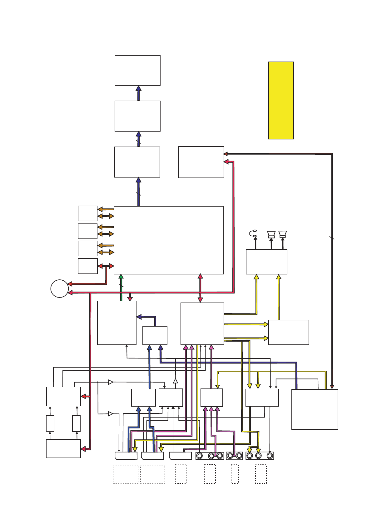
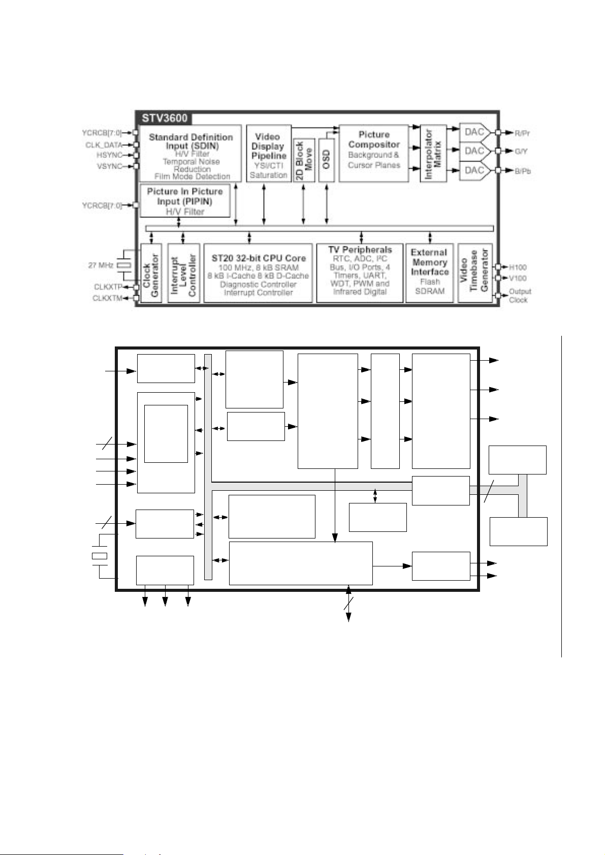
BLOCK DIAGRAM
This is a diagram for all models and therefore differs slightly from the actual block diagram.
LCD PANEL
LVDS
THC63
LVDM83R
LCD - TV
LVDS CABLE
10 PAIRS
BLOCK DIAGRAM
This is a diagram for all
models and therefore
differs slightly model by
model
9PIN DIN
SERVICE SOCKET
NVM
12C BUS
12C BUS
IC805
M29W160E
FLASH
IC804
SD RAM128MB
IC803
SD RAM128MB
IC802
M24C64
NVM
(EEPROM) 64KB
16KB
DATA
DATA
DATA
IC2001
IC1CCI
ADD-
RESS
ADD-
RESS
ADD-
RESS
STV2310
VIDEO PROCESSOR
SCALER IC
ADE3800XLM
IC8O1
STV3600
&
VIDEO PROCESSOR
Y/CR/CB
8 LINES
Y/PR/PB
12C BUS
IC1251
OR
RGB
3 LINES
BA7603F
Y/U/V SWITCH
AV RGB
OR
DIGITALY/U/V
IN
IC1801
SUB CPU
M16C/26
IC3451
STV8216
AUDIO PROCESSOR
12C BUS
I2C BUS
L & R
AUDIO
BUS0
(BBE)
BUS1
(MACH-3)
DIGITAL MODULE
CONTROL BUS
IC001
LA4919
AUDIO AMP
L & R AUDIO
FOR HEADPHONES
SPEAKERS
10WX2
L & R
AUDIO
IC3501
NJM2155M
SOUND
ENHANCEMENT
AUDIO PROCESSOR
ADDRESS/DATA/CLOCK
3 LINES
DIGITAL MODULE
CONTROL BUS
ANALOG
ANALOG
VIDEO
AV RGB
IN
DIGITAL
Y/U/V IN
AUDIO
Y/U/V
DIGITAL
VIDEO
L & R
DIGITAL
AUDIO
DIGITAL
AUDIO IN
TC4052
AV AUDIO IN
SWITCH
AUDIO IN
AV4 AUDIO IN
AUDIO
AV2
IC101
X121
IDA9886
VIF SAWF
AV1 AUDIO IN
AV2 AUDIO IN
AV OR DIGITAL
AV4
VIDEO
IN
AV1 AUDIO OUT
IC 1221
AV3 AUDIO IN
TV OUT1
IC1224
BA7626F
TV VIDEO
AV2
VIDEO
IN
SWITCH
AV3
VIDEO IN
IC1205
BA7603F
AV1
VIDEO
IN
RGB SWITCH
IF DETECTOR
12C BUS
SIF SAWF
X121
TV OUT2
12C BUS
AV2 RGB
SCART2-AV2
AV-LINK
RGB
V-I/O
IN
A-I/O
RC-IN
SCART3-AV3
AV-LINK
V - IN
A - IN
AV4
V - IN
A - IN
A - IN
A101
TUNER
SCART1-AV1
RGB
V-I/O
A-I/O
RC-IN
IC1221
BA7609F
DM OUT
AV2
AUDIO OUT
SWITCH
VIDEO
OUT
AUDIO OUT
V - OUT
A - OUT
ANALOG
VIDEO
VIDEO
OUT
DIGITAL
MODULE
DIGITAL
VIDEO
Page 4
-4-
N2WL
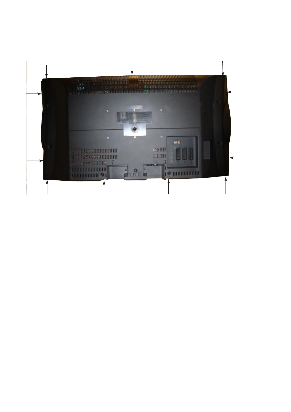
CABINET DISASSEMBLY
CABINET BACK DISASSEMBLY
1. Remove 11 screws marked A for 27”
2. Pull out the cabinet back.
A
A
A
A
A
A
A
A A
A
A
Page 5
-5-
N2WL
OPTION SETTING
[After replacing the Memory IC (IC802)]
The memory IC, IC802, stores the option data of the TV set and service adjustments data for each circuit, therefore,
when the memory IC is replaced, it should be set up following these settings and “SERVICE ADJUSTMENTS” on
the next page.
To enter to the Option Mode
+ Press and hold the F/OK button on the remote control and P▼ button on the front panel of the TV. The option
window will appear on the screen.
To set the option mode
+ Highlight the desired option item by using the P▲ or P▼ button .
+ To switch the option mode, use the
Volume - (LEFT) or Volume + (RIGHT) button.
+ The data which is set in the option mode is stored into the memory IC automatically.
Following table shows the available option items and default setting mode.
Exit from the Service Mode
+ Press the MENU button.
Option Mode Mode Description & Note
ON-TIMER ON or OFF On-timer available, default “OFF”
PLUG AND PLAY ON or OFF Plug and Play mode, default “ON”
WELCOME TEXT ON or OFF Display message when first set up, default “ON”
BBE ON or OFF BBE sound mode, default “ON”
AUTO VOLUME OFF or ON Default “OFF”
HEADPHONE ON or OFF Headphone control , default “OFF”
CRT 16:9 MODE ON or OFF Default “ON”
NOISE REDUCTION ON or OFF Default “ON”
COUNTRY UK, IRE, UK/IRE, EU TV system, default “EU”
RASTER ROTATION ON or OFF Default “OFF”
SESA ON or OFF Default “OFF”
DIGITAL RC ON or OFF Digital option, default “ON”
LIGHT MONITORING ON or OFF Ambient light control of LCD brightness,default “OFF”
VIDEO MUTE ON or OFF Default “OFF”
OPTION MODE FOR CE27LC4-C-00
ON-TIMER OFF
PLUG AND PLAY ON
WELCOME TEXT ON
BBE ON
AUTO VOLUME OFF
HEADPHONE OFF
16:9 MODE ON
NOISE REDUCTION ON
COUNTRY EU
RASTER ROTATION OFF
SESA OFF
DIGITAL RC ON
LIGHT MONITORING OFF
VIDEO MUTE OFF
Page 6

-6-
N2WL
SERVICE ADJUSTMENTS
INITIALISATION OF MEMORY IC
To initialise the memory IC (IC802), enter the service mode as below, navigate to “EEPROM Reset” and press OK
on the remote control. Turn the mains power off and on - the initialisation is now complete.
When initialised the memory IC and all of the setting data (option data and service adjustment data) stored in the IC
are reset to the default value. It is necessary to set the option settings, readjust the service adjustments and to
re-tune all the channels.
The available adjustment items are as follows;
TDA9885 : This can be adjusted for AGC.
Video : This can be adjusted for the service adjustment.
Others : ONLY use for greyscale adjustment
DO NOT ADJUST OTHER SETTINGS
[After replacing the Memory IC (IC803)]
The memory IC, IC802, stores the service adjustments data for each circuit, therefore, when the memory IC is
replaced, it should be programmed by using “OPTION SETTING” on previous page and the following adjustments.
While pressing the green button on the remote control press the
P▼ on the cabinet front.
The service menu appears.
Use the 6or 5 to highlight the service menu you require and press the F/OK button to enter.
Press the Menu button to navigate backwards through the service menus until menus disappear.
Note: Some items of the service adjustments for this chassis are controlled by the CPU, IC801, and the
adjustments are carried out by using the RC handset.
TO ENTER SERVICE ADJUSTMENTS
TO EXIT SERVICE ADJUSTMENTS
Service
SV V ers 042
Sound
Video
Other
STV8206
TDA9885
STV2310
ADE3800
WSS
EEPROM Reset
IMPORTANT NOTICE
Do not attempt to adjust service adjustments not listed on the above otherwise it may cause
loss of performance and product safety.
Page 7

-7-
N2WL
Service menu: Video
Enter the service adjustment menu as described on the previous page and select “Video” using
the P▼ or P▲ buttons and then press the F/OK button to enter.
Use the
P▼ or P▲ buttons to select the option, then press
the
F/OK button on the remote control to enter.
Service menu: Sound
Enter the service adjustment menu as described on the previous page and select “Sound” using
the P▼ or P▲ buttons and then press the F/OK button to enter.
Use the
P▼ or P▲ buttons to select the option, then
press the
F/OK button on the remote control to enter.
Service menu: TDA9885
Enter the service adjustment menu as described on the previous page and select “TDA9885”
using the
P▼ or P▲ buttons and then press the F/OK button to enter
Use the
P▼ or P▲ buttons to select the option,
then press the
F/OK button on the remote
control to enter.
Audio Menu
¥ VL’ AGC Ads
Prescl Scart
Prescl FM
Prescl Nicam
Reserve sound
0
3
10
10
13
VIDEO
G2 Alignment Config.
White Point R 41
White Point G 32
White Point B 36
Peak White Limiter 0
Black Level offset R 8
Black Level offset G 8
Gain pre-scale RGB 0
Fast blanking delay 0
Luma/Chroma delay 0
Restore default
TDA9885
Write 1 70
Page 8

-8-
N2WL
ADJUSTMENTS
IMPORTANT NOTICE
Do not attempt to adjust the following service adjustments except when adjustments are required in servicing
otherwise it may cause loss of performance and product safety.
1. Select the clearest VHF station
2. Connect a digital voltmeter to test point TP-A and GND
3. Enter service menu : TDA9885
4. With the P▼ or P▲ buttons select “Write 1”
5. Adjust using the or buttons until the readout from the voltmeter is 3.2 Vdc.
SCREEN ADJUSTMENT
1. Make sure the set is warm (20 mins)
2. Receive Black and White picture/pattern
3. Enter service menu “Others”
4. Use the +P and -P keys to navigate to item no 51
(white bal R) or no. 52 (white bal G)
5. Using the or buttons adjust to make the
white, white.
GREY SCALE ADJUSTMENT
AGC ADJUSTMENT
Page 9
-9-
N2WL
CPU PORT FUNCTIONS
IC801
36
37
38
39
40
ADDR_9
ADDR_11
ADDR_13
ADDR_12
41
ADDR_8
42
ADDR_7
43
ADDR_6
ADDR_5
44
45
ADDR_4
CKOUT_SDRAM
46
VDD33_IO
47
48
VSS_IO
49
CKIN_SDRAM
ADDR_3
50
ADDR_2
51
ADDR_1
52
ADDR_0
53
ADDR_10
54
ADDR_16
55
ADDR_15
56
NOT_CS_SDRAM
57
NOT_RAS
58
59
NOT_CAS
RD_NOTWR
60
NOT_BE0
61
VDD12_CORE
62
VSS
63
VDD33_IO
64
VSS_IO
65
NOT_CS_FLASH
66
ADDR_17
67
68
ADDR_18
ADDR_19
69
ADDR_14
70
VDD12_CORE
71
VSS
72
FLASH_D15
73
74
FLASH_D7
75
FLASH_D14
FLASH_D6
76
77
FLASH_D13
FLASH_D5
78
79
FLASH_D12
FLASH_D4
80
NOT_BE1
VSS_IO82VDD33_IO83FLASH_D1184FLASH_D385FLASH_D1086FLASH_D287FLASH_D988FLASH_D189FLASH_D890FLASH_D091VSS92VDD12_CORE93TMS94TCK95TDO96TDI97TRST98NRESET99VSS
81
35
VSS_IO
33
34
VDD33_IO
32
SDRAM_D9
SDRAM_D8
30
31
SDRAM_D11
SDRAM_D10
28
29
SDRAM_D13
SDRAM_D12
26
27
SDRAM_D15
SDRAM_D14
24
25
VDD33_IO
VSS_IO
18
19
20
21
22
23
SDRAM_D5
SDRAM_D4
SDRAM_D3
SDRAM_D2
SDRAM_D1
SDRAM_D0
IC801
STV3600BM
VDD12_CORE
VCC12_PLL2
GND_PLL2
VCC12_PLL3
100
101
102
103
16
17
SDRAM_D7
SDRAM_D6
GND_PLL3
XTALIN
104
105
14
15
VSS
VDD12_CORE
XTALOUT
VCC12_IO
106
107
12
13
VDD33_IO
GND_IO
108
VSS_IO
CLKXTM
109
10
11
PORTA3/LCD_BR
PORTA2/PLL_LOCK
CLKXTP
VSS_PLL
110
111
8
9
PORTD3/AV_CTL_B
PORTD6/POWER_FAIL2
VDD12_PLL
SHIELD_PLL
112
113
5
6
7
PORTD2/50/60HZ
PORTD1/LCD_ON
PORTD0/AV_CTL_A
PORTA5/MUTE/FLASH_RXD
VSYNC
HSYNC
CLK_DATA
114
115
116
1
2
3
4
PORTC7/SCL
PORTC6/SDA
PORTC5/SCL_NVM
PORTC4/SDA_NVM
CLK_DFL/PIP_CLK
VCC33_DAC
GND_DAC
PB_B
GND_REXT
REXT
SHIELD_ADCDAC
GND_ADC
VCC33_ADC
PORTD5/POWER1
PORTB0/POWER_SW
PORTB1/KEYBOARD
PORTB2/SC1_8
PORTB3/SC2_8
PORTB4/SC3_8
PORTB5/AGC
VSS_IO
VDD33_IO
PORTA7/STATUS/FAN_CTL
PORTA6/SEL
PORTA4/LED/FLASH_TXD
PORTD7/POWER_INFO
PORTA1/POWER_FAIL1
PORTD4/RC_IN
PORTA0/NRESET_OUT
PORTC0/SDA_ADE3800
PORTC1/SCL_ADE3800
PORTC2/AV_CTL_C
PORTC3/POWER3
VDD12_CORE
YCRCB7
YCRCB6
YCRCB5
YCRCB4
YCRCB0
YCRCB1
YCRCB2
YCRCB3
117
118
119
120
H100
V100
Y_G
PR_R
VSS
160
159
158
157
156
155
154
153
152
151
150
149
148
147
146
145
144
143
142
141
140
139
138
137
136
135
134
133
132
131
130
129
128
127
126
125
124
123
122
121
Page 10
-10-
N2WL
IC801
IC BLOCK DIAGRAMS
NRESET
YCRCB[7:0]
CLK_DATA
HSYNC
VSYNC
YCRCB[7:0]
27 MHz
Crystal
Build-Up
Counter
HV Filter
8
TNR
SDIN
Block
8
PIPIN
H/V Filter
Clock
Generator
CLKXTP
CLKXTM
CLK_DFL
Video
Pipeline
YSI/CTI
Saturation
OSD
Pipeline
ST20 Core
TV Peripherals
TV Chassis Control
Compositor
Picture
Comp.
Cursor
BG
Plane
Fast Blanking
CSA
2D
Block Move
30
I/Os
Triple
DAC
EMI4
Time Base
Generator
PR_R
Y_G
PB_B
SDRAM
16/32
Flash
H100
V100
Page 11
-11-
N2WL
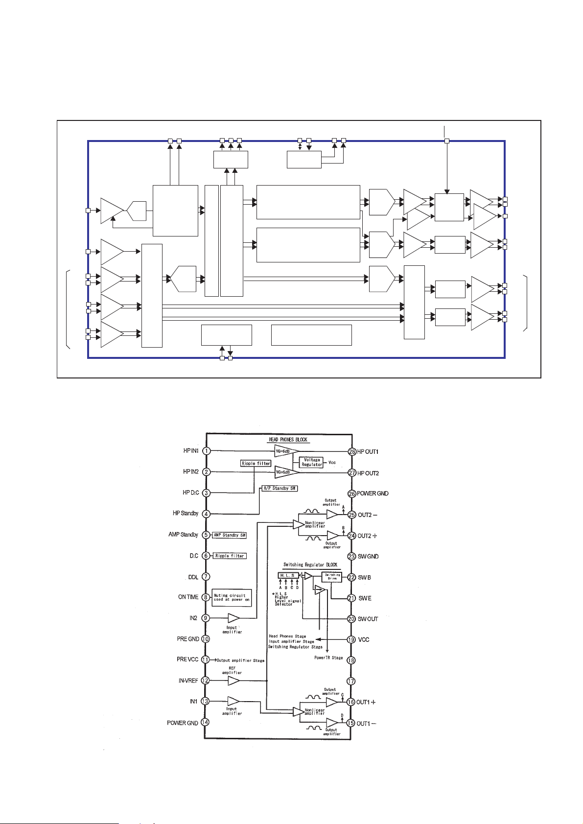
IC001 LA4919NE <Audio Output>
IC BLOCK DIAGRAMS
IC3451 STV8216T <NICAM & Stereo Sound Decoder>
S
Sound
Monon
nutS
Demodulation
Multi-Standard
DiitalStereo
Demodulator
Diital
udio
Matri
udioMatriin
udioroein
oudeaerudioroein
eadoneudioroein
oerSulManaement
oudeaer
Suooer
eadone
ututSart
Page 12

-12-
N2WL
BLOCK DIAGRAMS
IC2001
Page 13

-13-
N2WL
PIN DESCRIPTION OF SEMICONDUCTORS
● Diode
● Transistor/FET
● IC
FET
● Diode
K
A
● Transistor/FET
K
A
K
AA
KK
A
K
K
K: Cathode
A: Anode
A
A
C
B
C
E
● IC
1
Index
C1
3
2
E
C2
Vdd
1
C1
C2
B1 B2
E
B2
GND
C
E
2
C
E
B
C
3
E
B
B
2
3
1
E
C1
CBE
C2
E
3
2
C
B
B1
1
B2
C
BE
B1
RESET
Index
1
2
N
1
2
N
C2
E2 C1
B1
B2
B1
B2
(IN)
E1
1
(GND)
2
4
5
6
Index
E1
C1
C2
E2
3
(OUT)
C: Collector
B: Base
E: Emitter
G
3
2
1
Index
D: Drain
G: Gate
S: Source
S
G
D
S
D
3
21
5
4
Index
N
1
Index
Index
Index
N
1
N
1
N
1
Index
N
1
N
1
Index
Page 14

-14-
9
N2WL
PARTS DESCRIPTION AND READING IN SCHEMATIC DIAGRAM
1. The parts specification of resistors, capacitors and
coils are expressed in designated code. Please
check the parts description by the following code
table.
2. Some of transistors and diodes are indicated in
mark for the substitution of parts name. Please
check the parts name by the following code table.
3. Voltages and waveforms were taken with a video
colour bar signal(1Vp-p at 75 ohms terminated) and
controls to normal.
4. Voltages were taken with a high-impedance digital
voltmetre.
Example 2000 K K 1000 BG
Characteristic
Example 160 E M 10
Capacitance value
Tolerance
Type
Rated voltage
Excepting electric capacitors, all
capacitance values of less than 1
are expressed in µF and more
than 1 are in pF.
Example L2 C1 4R7 K N
Tolerance
Inductance value
Manufacture code
Unique code
Mark Material
E Electrolytic
P Electrolytic (non-Polarised)
C Ceramic (temperature compensation)
K Ceramic
F Polyester
N Polypropylene
M Metalised polypropylene
H Metalised polypromylar
B Ceramic (semiconductor)
G Metalised polyester
Y Composite film
S Styrol
T Tantalum oxide solid electrolytic
U Organic semiconductive electrolyte
D Electric double layer electrolytic
Mark Tolerance
A not specified
B ±0.1
C ±0.25
D ±0.5
F±1
G±2
E ±2.5
H±3
J±5
K±0
M±20
N±30
P +100 -0
Q +30 -10
T +50 -10
U +75 -10
V +20 -10
W +100 -10
X +40 -20
Y +150 -10
Z +80 -20
Mark Tolerance (nH) Mark Tolerance (%)
C ±0.25 G ±2
D ±0.5 J ±5
S ±0.3 K ±10
A ±0.2 L ±15
M±20
Coil Reading
Capacitor Reading
Example 1/2 D J 10K B
Example 6 W K 8.2
Example 1/2 C K 1M
Resistor Reading
Characteristic
Z (Carbon fuse)
B (Non-burnable)
Resistance value
Tolerance (see below table)
Material (see below table)
Rated wattage (W)
K indicates in KΩ
M indicate in MΩ
Note: Resistor which is indicated with resistance value only are
1/6W carbon resistor. Resistor which is indicated with material, tolerance and value are 1/4W rated wattage.
Mark Material
D Carbon
N Metal film
S Oxide metal film
C Solid
G Metal glaze
W Wire wounding or cement
H Ceramic
F Fusible
Mark Tolerance
A ±0.05
B ±0.1
C ±0.25
D ±0.5
F±1
G±2
J±5
K±10
M±20
P +5 -15
Z used in 0 ohm
● Material table
● Tolerance table
● Material table
● Tolerance table
Mark Type number
-- 1S1555,1S2473,1S2076,1SS133,DS442,1SS176
K 1S1555,1S2473,1S2076,DS442
L 1S1555,1S2076A,1S2471
M 1SS133,1SS176,GMA01
N 1S1555,1S2473,1S2076,1SS133,DS442,1SS176,1N4148
P 1S1555,1S2076A,1S2471,1N4148
R 1S1555,1S2076,1S2473,DS442,1N4148
AA 1S1555,1S2076,1S2473,1SS133,DS442,1SS176,1N4148,GMA01
● Diode
Mark Type number
-- 2SC536 2SC945A 2SC1815 2SC1740 2SC1740S KSC945C
A E, F, G P, Q, R O, Y, G Q, R, S Q, R, S
B E, F, G P, Q, R O, Y, G Q, R, S
D F, G P, Q Y, G Q, R, S
F F, G P G R, S
H F, G P, Q Y, G Q, R, S Y, G
I E, F, G P, Q, R O, Y, G Q, R, S Y, G
G F, G P G R, S G
AD F, G Q, R Y, GR Q, R, S
AE E, F, G Q, R O, Y, GR Q, R, S
● Transistor (NPN type)
Mark Type number
-- 2SA608 2SA564A 2SA1015 2SA933 2SA933S KSA733C
Y E, F Q, R O, Y, G Q, R
WF R Y, GR
V E, F Q, R O, Y, G Q, R Y, G
U F R Y, G R G
Z E, F Q, R O, Y, G Q, R Q, R
AB F R Y Q, R
AE E, F Q, R O, Y R
● Transistor (PNP type)
Diode/Transistor Type Reading
Page 15

-15-
N2WL
CABINET PARTS LIST FOR MODEL CE27LC4-C-00
CABINET PARTS
1 610 319 4578 CABINET BACK-N2WJ
2 610 319 4554 CABINET FRONT-N2WJ
3 645 076 4936 BADGE,SANYO*53.5X12L53.5
4 610 320 2600 ASSY,STAND BASE-N2WJ
5 610 319 4547 BUTTON UNITED-N2W
6 610 319 4639 DEC IND-N2WJ
7 610 319 4622 DOOR-N2WJ
8 610 319 6572 MOUNTING BRKT-N2WJ
9 610 319 4769 STAND BASE-N2WJ
10 610 319 4776 STAND COVER-N2WJ
11 610 319 4806 TERMINAL BASE-N2WJ
12 645 079 9488 PAD (BLACK) RICHCO RBS-24
ACCESSORIES
13 645 075 1394 ASSY,REMOCON JXPTA
1AV4D11B06800 BATT ENERGIZER R03SHP2VP
665 000 4016 INST MANUAL - N2WL (1)
665 000 4023 INST MANUAL - N2WL (2)
665 000 4030 INST MANUAL - N2WL (3)
Item Part No. Description Item Part No. Description
Note: Parts order must contain Service Ref. No., Part No., and descriptions.
1
13
11
1
2
65
3
4
8
12 x 4
9
10
DS
Page 16

N2WL
-16-
CHASSIS ELECTRICAL PARTS LIST
Product safety should be considered when a component replacement is made in any area of a receiver.
Components indicated by a mark in this parts list and the circuit diagram show components whose value have
special significance to product safety. It is particularly recommended that only parts specified on the following
parts list be used for components replacement pointed out by the mark .
013N2WJ ELECTRICAL PARTS
LIQUID CRYSTAL DISPLAY
EL901 645 067 6215 LCD(V270W1-L04)
ELECTRICAL
FN902 645 068 3763 MOTOR,FAN DC
KLP1-PN 610 322 8631 CORD,30P 1.25MM(LVDS)
KSPL-A 645 033 2227 CORE, FERRITE
KSPR-A 645 033 2227 CORE, FERRITE
K8D-KD 645 078 3920 FLEXIBLE FLAT CABLE
SP901 652 001 4473 SPEAKER,8
SP902 652 001 4473 SPEAKER,8
W900 645 012 7632 EURO PLUG +2P HOUSE @ 2.1
W900-A 645 020 3640 FERRITE RING
Z801 610 322 9201 SHIELD CASE SCALER-N2WJ
1AA0B10N137BA ASSY,PWB,SIGNAL,N2WL
CAPACITOR
C001 403 314 5915 GRM21BR71C474KA01L PT297
C002 403 314 5915 GRM21BR71C474KA01L PT297
C003 403 387 6918 ELECT 100U M 25V
C004 403 387 7212 ELECT 47U M 25V
C005 403 184 8313 ELECT 22U M 25V
403 398 4712 25CE22BS 22U M 25V
C006 403 314 5915 GRM21BR71C474KA01L PT297
C007 403 184 8511 ELECT 2.2U M 50V
403 398 6518 50CE2R2BS 2.2U M 50V
C008 403 314 5915 GRM21BR71C474KA01L PT297
C009 403 155 2319 GRM188R71H472KA01D PT115
C010 403 155 2319 GRM188R71H472KA01D PT115
C013 403 113 3815 GRM188R71H102KA01D PT115
C014 403 042 4875 ELECT 1000U M 16V
C015 403 372 7517 CERAMIC 2.2U K 6.3V
C019 403 207 0317 GRM21BF51C105ZA01L PT297
C020 403 207 0317 GRM21BF51C105ZA01L PT297
C021 403 281 5215 GRM188F51C224ZA01D PT115
C022 403 281 5215 GRM188F51C224ZA01D PT115
C023 403 281 5215 GRM188F51C224ZA01D PT115
C024 403 281 5215 GRM188F51C224ZA01D PT115
C025 403 336 3517 CERAMIC 0.47U K 16V
C026 403 336 3517 CERAMIC 0.47U K 16V
C027 403 387 6918 ELECT 100U M 25V
C028 403 387 6918 ELECT 100U M 25V
C031 403 215 2211 GRM188R71H103KA01D PT115
C032 403 215 2211 GRM188R71H103KA01D PT115
C033 403 215 2211 GRM188R71H103KA01D PT115
C034 403 215 2211 GRM188R71H103KA01D PT115
C041 403 281 5215 GRM188F51C224ZA01D PT115
C042 403 281 5215 GRM188F51C224ZA01D PT115
C043 403 281 5215 GRM188F51C224ZA01D PT115
C044 403 281 5215 GRM188F51C224ZA01D PT115
Ref. No.
Part No.
Description
Chassis construction
CE27LC4-C-00
013N2WL ELECTRICAL PARTS (PAGE 16)
1AA0B10N137BA ASSY,PWB,SIGNAL,N2WL (PAGE 16 -22)
1AA0B10N1370B ASSY,PWB,CONTROL,N2WJ (PAGE 22)
1AA0B10N13900 ASSY,PWB,POWER,N2WJ (PAGE 22-25)
1AA0B10N13800 ASSY,PWB,SCAL,N2WJ (PAGE 25-29)
Read description in the Capacitor and Resistor as follows:
CAPACITOR
CERAMIC 100P K 50V
Tolerance Symbols:
Less than 10PF
A: Not specified B: ±0.1PF C:±0.25PF
D: ±0.5PF F: ±1PF G: ±2PF
R: ±0.25-0PF S: ±0-0.25PF E: +0-1PF
More than 10PF
A: Not specified B: ±0.1% C:±0.25%
D: ±0.5% F: ±1% G: ±2%
H: ±3% J: ±5% K: ±10%
L: ±15% M: ±20% N: ±30%
P: +100-0% Q: +30-10% T: +50-10%
U: +75-10% V: +20-10% W:+100-10%
X: +40-20% Y: +150-10% Z: +80-20%
Material:
CERAMIC............Ceramic
MT-PAPER ..........Metallized Paper
POLYESTER ......Polyester
MT-POLYEST......Metallized Polyester
POLYPRO............Polypropylene
MT-POLYPRO ....Metallized Polypropylene
COMPO FILM......Composite film
MT-COMPO ........Metallized Composite
STYRENE............Styrene
TA-SOLID............Tantalum Solid
AL-SOLID............Aluminium Solid
ELECT ................Electrolytic
NP-ELECT ..........Non-polarised Electrolytic
OS-SOLID ..........Aluminium Solid with Organic Semiconductive Electrolytic
DL-ELECT ..........Double Layered Electrolytic
RESISTOR
CARBON 4.7K J A 1/4W
Rated Wattage
Performance Symbols:
A: General B: Non flammable Z: Low noise
Other: Temperature coefficient
Tolerance Symbols:
A: ±0.05% B: ±0.1% C: ±0.25% D: ±0.5%
F: ±1% G: ±2% J: ±5% K: ±10%
M:±20% P: +5-15%
Rated value, ohms:
K: 1,000, M: 1,000,000
Material:
CARBON ............Carbon
MT-FILM..............Metal Film
OXIDE-MT ..........Oxide Metal Film
SOLID..................Composition
MT-GLAZE ..........Metal Glaze
WIRE WOUND ....Wire Wound
CERAMIC RES....Ceramic
FUSIBLE RES ....Fusible
Rated Voltage
Rated value: P=pico farad, U=Micro farad
Note: Parts order must contain Service Ref. No., Part No., and descriptions.
!
!
Page 17

-17-
N2WL
Part No.
Ref. No.
Part No.
Description
Ref. No.
Description
C049 403 155 2319 GRM188R71H472KA01D PT115
C050 403 155 2319 GRM188R71H472KA01D PT115
C1003 403 157 3611 GRM1885C1H101JZ01D PT115
C1005 403 157 3611 GRM1885C1H101JZ01D PT115
C1006 403 157 3611 GRM1885C1H101JZ01D PT115
C1007 403 157 3611 GRM1885C1H101JZ01D PT115
C1008 403 157 3611 GRM1885C1H101JZ01D PT115
C1009 403 157 3611 GRM1885C1H101JZ01D PT115
C101 403 184 8412 ELECT 4.7U M 25V
403 391 5716 25CE4R7BS 4.7U M 25V
C1010 403 215 2211 GRM188R71H103KA01D PT115
C1011 403 174 6213 ELECT 47U M 10V
403 398 3210 10CE47BS 47U M 10V
C1012 403 157 3611 GRM1885C1H101JZ01D PT115
C1013 403 323 8815 GRM21BF51C225ZA01K PT115
C1014 403 323 8815 GRM21BF51C225ZA01K PT115
C1015 403 157 3611 GRM1885C1H101JZ01D PT115
C1016 403 157 3611 GRM1885C1H101JZ01D PT115
C1017 403 157 3611 GRM1885C1H101JZ01D PT115
C1018 403 157 3611 GRM1885C1H101JZ01D PT115
C1019 403 157 3611 GRM1885C1H101JZ01D PT115
C102 403 215 2211 GRM188R71H103KA01D PT115
C1025 403 157 3611 GRM1885C1H101JZ01D PT115
C1026 403 157 3611 GRM1885C1H101JZ01D PT115
C1027 403 157 3611 GRM1885C1H101JZ01D PT115
C1028 403 157 3611 GRM1885C1H101JZ01D PT115
C103 403 224 3414 ELECT 220U M 6.3V
C1031 403 157 3611 GRM1885C1H101JZ01D PT115
C1032 403 323 8815 GRM21BF51C225ZA01K PT115
C1033 403 323 8815 GRM21BF51C225ZA01K PT115
C1034 403 157 3611 GRM1885C1H101JZ01D PT115
C1036 403 323 8815 GRM21BF51C225ZA01K PT115
C1037 403 323 8815 GRM21BF51C225ZA01K PT115
C1038 403 323 8815 GRM21BF51C225ZA01K PT115
C1039 403 323 8815 GRM21BF51C225ZA01K PT115
C104 403 215 2211 GRM188R71H103KA01D PT115
C1041 403 157 3611 GRM1885C1H101JZ01D PT115
C1042 403 157 3611 GRM1885C1H101JZ01D PT115
C1043 403 157 3611 GRM1885C1H101JZ01D PT115
C1044 403 157 3611 GRM1885C1H101JZ01D PT115
C1045 403 207 0317 GRM21BF51C105ZA01L PT297
C1046 403 207 0317 GRM21BF51C105ZA01L PT297
C1047 403 207 0317 GRM21BF51C105ZA01L PT297
C1050 403 215 2211 GRM188R71H103KA01D PT115
C106 403 073 1210 CERAMIC 0.033U K 50V
C107 403 073 1210 CERAMIC 0.033U K 50V
C108 403 215 2211 GRM188R71H103KA01D PT115
C111 403 215 2211 GRM188R71H103KA01D PT115
C1116 403 207 0317 GRM21BF51C105ZA01L PT297
C1117 403 207 0317 GRM21BF51C105ZA01L PT297
C1118 403 207 0317 GRM21BF51C105ZA01L PT297
C112 403 368 7316 CERAMIC 10U M 6.3V
403 370 7618 CERAMIC 10U M 603V
C113 403 155 2319 GRM188R71H472KA01D PT115
C114 403 155 2319 GRM188R71H472KA01D PT115
C115 403 155 2319 GRM188R71H472KA01D PT115
C116 403 172 6116 GRM1885C1H271JD01D PT115
C117 403 073 1210 CERAMIC 0.033U K 50V
C120 403 215 2211 GRM188R71H103KA01D PT115
C1200 403 323 8815 GRM21BF51C225ZA01K PT115
C1202 403 175 4218 ELECT 47U M 10V
403 398 3210 10CE47BS 47U M 10V
C1204 403 207 0317 GRM21BF51C105ZA01L PT297
C1205 403 323 8815 GRM21BF51C225ZA01K PT115
C1208 403 207 0317 GRM21BF51C105ZA01L PT297
C121 403 157 6513 CERAMIC 390P K 50V
C1211 403 153 9310 GRM1885C1H820JZ01D PT115
C1212 403 153 9310 GRM1885C1H820JZ01D PT115
C1213 403 323 8815 GRM21BF51C225ZA01K PT115
C1214 403 153 9310 GRM1885C1H820JZ01D PT115
C1215 403 323 8815 GRM21BF51C225ZA01K PT115
C1218 403 153 9310 GRM1885C1H820JZ01D PT115
C122 403 149 9218 GRM188F51H103ZA01D PT115
C123 403 314 5915 GRM21BR71C474KA01L PT297
C1230 403 164 0214 GRM188F51E104ZA01D PT115
C125 403 139 7118 GRM1885C1H120JZ01
C1254 403 153 9310 GRM1885C1H820JZ01D PT115
C1255 403 323 8815 GRM21BF51C225ZA01K PT115
C126 403 215 2211 GRM188R71H103KA01D PT115
C127 403 215 2211 GRM188R71H103KA01D PT115
C131 403 215 2211 GRM188R71H103KA01D PT115
C132 403 215 2211 GRM188R71H103KA01D PT115
C133 403 184 8214 UWX1E100MCL1GB
403 398 4415 25CE10BS
C134 403 149 9218 GRM188F51H103ZA01D PT115
C137 403 256 5011 CERAMIC 560P J 50V
C138 403 256 5011 CERAMIC 560P J 50V
C141 403 314 5915 GRM21BR71C474KA01L PT297
C142 403 269 5916 GRM219R71C224KC01D PT115
C143 403 155 2111 GRM188R71H152KD01D PT115
C144 403 155 2418 GRM188R71H562KA01D PT115
C146 403 113 3815 GRM188R71H102KA01D PT115
C147 403 113 3815 GRM188R71H102KA01D PT115
C148 403 157 7114 GRM188R71H272KA01D PT115
C1841 403 184 8313 ELECT 22U M 25V
403 398 4712 25CE22BS 22U M 25V
C1851 403 184 8313 ELECT 22U M 25V
403 398 4712 25CE22BS 22U M 25V
C1858 403 149 9218 GRM188F51H103ZA01D PT115
C1861 403 149 9218 GRM188F51H103ZA01D PT115
C1862 403 184 8313 ELECT 22U M 25V
403 398 4712 25CE22BS 22U M 25V
C1863 403 164 0214 GRM188F51E104ZA01D PT115
C3406 403 164 0214 GRM188F51E104ZA01D PT115
C3408 401 105 7919 MT-GLAZE 0.000 ZA 1/16W
C3431 403 157 3611 GRM1885C1H101JZ01D PT115
C3433 403 157 3611 GRM1885C1H101JZ01D PT115
C3441 403 157 3611 GRM1885C1H101JZ01D PT115
C3442 403 279 4312 GRM21BR71C334KA01L PT297
C3443 403 157 3611 GRM1885C1H101JZ01D PT115
C3444 403 279 4312 GRM21BR71C334KA01L PT297
C3445 403 157 3611 GRM1885C1H101JZ01D PT115
C3446 403 279 4312 GRM21BR71C334KA01L PT297
C3447 403 157 3611 GRM1885C1H101JZ01D PT115
C3448 403 279 4312 GRM21BR71C334KA01L PT297
C3449 403 164 0214 GRM188F51E104ZA01D PT115
C3450 403 184 8214 UWX1E100MCL1GB
403 398 4415 25CE10BS
C3451 403 269 5916 GRM219R71C224KC01D PT115
C3452 403 164 0214 GRM188F51E104ZA01D PT115
C3454 403 157 3611 GRM1885C1H101JZ01D PT115
C3455 403 164 0214 GRM188F51E104ZA01D PT115
C3456 403 207 0317 GRM21BF51C105ZA01L PT297
C3457 403 368 7316 CERAMIC 10U M 6.3V
C3458 403 368 7316 CERAMIC 10U M 6.3V
C3461 403 164 0214 GRM188F51E104ZA01D PT115
C3462 403 184 8214 UWX1E100MCL1GB
403 398 4415 25CE10BS
C3463 403 164 0214 GRM188F51E104ZA01D PT115
C3464 403 184 8214 UWX1E100MCL1GB
403 398 4415 25CE10BS
C3465 403 164 0214 GRM188F51E104ZA01D PT115
C3466 403 184 8214 UWX1E100MCL1GB
403 398 4415 25CE10BS
C3467 403 164 0214 GRM188F51E104ZA01D PT115
C3468 403 184 8214 UWX1E100MCL1GB
403 398 4415 25CE10BS
C3469 403 164 0214 GRM188F51E104ZA01D PT115
C3470 403 184 8214 UWX1E100MCL1GB
C3477 403 184 8214 UWX1E100MCL1GB
Page 18

-18-
N2WL
Ref. No.
Part No.
Description
Ref. No.
Part No.
Description
403 398 4415 25CE10BS
C3478 403 164 0214 GRM188F51E104ZA01D PT115
C3481 403 155 4214 GRM1885C1H150JD01D PT115
C3482 403 139 7316 GRM1882C1H180JA01D PT115
C3483 403 164 0214 GRM188F51E104ZA01D PT115
C3484 403 164 0214 GRM188F51E104ZA01D PT115
C3486 403 164 0214 GRM188F51E104ZA01D PT115
C3487 403 178 6318 ELECT 100U M 6.3V
403 391 5815 6.3CE100BS 100U M 6.3V
C3501 403 387 6918 ELECT 100U M 25V
C3502 403 325 6314 CERAMIC 0.22U K 10V
C3503 403 325 6314 CERAMIC 0.22U K 10V
C3504 403 164 0214 GRM188F51E104ZA01D PT115
C3505 403 272 5613 CERAMIC 0.033U K 16V
C3506 403 155 2210 GRM188R71H332KA01D PT115
C3507 403 184 8214 UWX1E100MCL1GB
C3508 403 184 8214 UWX1E100MCL1GB
C3509 403 155 2210 GRM188R71H332KA01D PT115
C3510 403 272 5613 CERAMIC 0.033U K 16V
C3511 403 207 0317 GRM21BF51C105ZA01L PT297
C3512 403 184 8214 UWX1E100MCL1GB
403 398 4415 25CE10BS
C3513 403 368 7316 CERAMIC 10U M 6.3V
403 370 7618 CERAMIC 10U M 603V
C3514 403 207 0317 GRM21BF51C105ZA01L PT297
C3515 403 368 7316 CERAMIC 10U M 6.3V
403 370 7618 CERAMIC 10U M 603V
C6602 403 149 9218 GRM188F51H103ZA01D PT115
C6604 403 397 6014 ELECT 1000U M 10V
C6618 403 397 6717 ELECT 470U M 25V
C6624 403 164 0214 GRM188F51E104ZA01D PT115
C6626 403 387 6918 ELECT 100U M 25V
C6628 403 397 6014 ELECT 1000U M 10V
C6630 403 178 6318 ELECT 100U M 6.3V
403 391 5815 6.3CE100BS 100U M 6.3V
C6632 403 279 4312 GRM21BR71C334KA01L PT297
C6633 403 178 6318 ELECT 100U M 6.3V
403 391 5815 6.3CE100BS 100U M 6.3V
C6634 403 279 4312 GRM21BR71C334KA01L PT297
C6635 403 178 6318 ELECT 100U M 6.3V
403 391 5815 6.3CE100BS 100U M 6.3V
C6636 403 279 4312 GRM21BR71C334KA01L PT297
C6637 403 178 6318 ELECT 100U M 6.3V
403 391 5815 6.3CE100BS 100U M 6.3V
DIODE
D001 407 149 6324 DIODE SFPB-54V
D1001 407 206 5618 ZENER D. UDZS-TE-1710B
D1002 407 206 5618 ZENER D. UDZS-TE-1710B
D1003 407 206 5618 ZENER D. UDZS-TE-1710B
D1004 407 206 5618 ZENER D. UDZS-TE-1710B
D1005 407 206 5618 ZENER D. UDZS-TE-1710B
D1006 407 206 5618 ZENER D. UDZS-TE-1710B
D1007 407 206 5618 ZENER D. UDZS-TE-1710B
D1008 407 206 5618 ZENER D. UDZS-TE-1710B
D1009 407 206 5618 ZENER D. UDZS-TE-1710B
D101 407 149 0817 DIODE 1SS355-TE-17
D1012 407 206 5618 ZENER D. UDZS-TE-1710B
D1013 407 206 5618 ZENER D. UDZS-TE-1710B
D1014 407 206 5618 ZENER D. UDZS-TE-1710B
D1017 407 206 5618 ZENER D. UDZS-TE-1710B
D1018 407 206 5618 ZENER D. UDZS-TE-1710B
D1019 407 206 5618 ZENER D. UDZS-TE-1710B
D102 407 149 0817 DIODE 1SS355-TE-17
D103 407 149 0817 DIODE 1SS355-TE-17
D104 407 228 4910 ZENER DIODE UDZS33B-TE-17
D1058 407 206 5618 ZENER D. UDZS-TE-1710B
D1201 407 149 0817 DIODE 1SS355-TE-17
D1202 407 206 5618 ZENER D. UDZS-TE-1710B
D1203 407 206 5618 ZENER D. UDZS-TE-1710B
D1204 407 149 0817 DIODE 1SS355-TE-17
D1205 407 206 5618 ZENER D. UDZS-TE-1710B
D1206 407 206 5618 ZENER D. UDZS-TE-1710B
D121 407 166 1118 DIODE 1SS356-TW11
D1841 407 149 0817 DIODE 1SS355-TE-17
D1842 407 149 0817 DIODE 1SS355-TE-17
D1856 407 201 2721 DIODE RB051L-40-TE25
D202 407 206 5618 ZENER D. UDZS-TE-1710B
D3443 407 206 5618 ZENER D. UDZS-TE-1710B
D3444 407 206 5618 ZENER D. UDZS-TE-1710B
D3501 407 210 5413 DIODE RB551V-30-TE-17
D6601 407 149 0817 DIODE 1SS355-TE-17
D6608 407 149 0817 DIODE 1SS355-TE-17
D6611 407 149 0817 DIODE 1SS355-TE-17
D6613 407 149 0817 DIODE 1SS355-TE-17
D6618 407 149 0817 DIODE 1SS355-TE-17
INTEGRATED CIRCUIT
IC001 409 591 8707 IC LA4919N-E
IC001A 610 315 3452 HEAT SINK
IC101 409 549 8219 IC TDA9886TS/V4
IC1205 409 311 4121 IC BA7603F
IC1222 409 051 2722 IC TC4052BF(EL)
IC1224 409 631 2217 IC BA7626F
IC1841 409 039 6322 IC NJM2903M-T2
409 644 2013 IC BA2903F
IC1851 409 039 6629 IC NJM2904-T2
409 644 1917 IC BA2904F
IC3451 409 550 6815 IC STV8216T
IC3501 409 501 0411 IC NJM2155M
IC6604 409 493 2912 IC SI-3012LU-TL
IC6606 409 503 8019 IC BA05SFP
IC6608 409 578 0314 IC BA18BC0FP
IC6642 409 588 6313 IC BA33BC0FP
COIL
L001 645 066 2416 INDUCTOR,180U M
L002 645 036 3894 BLM21PG221SN1D E258
L003 645 004 0351 INDUCTOR 12U K
L004 645 004 0351 INDUCTOR 12U K
L1001 645 036 3894 BLM21PG221SN1D E258
L1001A 645 036 3894 BLM21PG221SN1D E258
L1002 645 036 3894 BLM21PG221SN1D E258
L1002A 645 036 3894 BLM21PG221SN1D E258
L1003 645 036 3894 BLM21PG221SN1D E258
L101 645 049 6875 IMPEDANCE,1000 OHM P
L102 645 075 7419 INDUCTOR,390U J
L103 645 059 2782 INDUCTOR,47U M
L1201 645 037 1615 SMDCOIL LEM2520T4R7J
L1202 645 037 1615 SMDCOIL LEM2520T4R7J
L1203 645 037 1615 SMDCOIL LEM2520T4R7J
L1204 645 037 1615 SMDCOIL LEM2520T4R7J
L1205 645 037 1615 SMDCOIL LEM2520T4R7J
L1851 645 033 7918 INDUCTOR,10U M
L1852 645 036 3894 BLM21PG221SN1D E258
L1853 645 036 3894 BLM21PG221SN1D E258
L3452 645 036 3894 BLM21PG221SN1D E258
L3453 645 036 3894 BLM21PG221SN1D E258
TRANSISTOR
Q001 406 017 2400 TR BC847B,215
405 014 4618 TR 2SC2412KT146/S
405 015 8724 TR 2SC2812TR 2SC2812-L6-T
405 015 8922 TR 2SC2812-L7-TA
405 163 1612 TR 2SC2812TR 2SC2812-L6-T
405 1631 711 TR 2SC2812-L7-TA
405 173 9813 TR 2SC3928A1R
405 173 9912 TR 2SC3928A1S
Q002 405 118 5729 TR 2SD2198-R-DL
Q003 406 017 2400 TR BC847B,215
405 014 4618 TR 2SC2412KT146/S
Page 19

-19-
N2WL
Ref. No.
Part No.
Part No.Description
Ref. No. Description
405 015 8724 TR 2SC2812TR 2SC2812-L6-T
405 015 8922 TR 2SC2812-L7-TA
405 163 1612 TR 2SC2812TR 2SC2812-L6-T
405 163 1711 TR 2SC2812-L7-TA
405 173 9813 TR 2SC3928A1R
405 173 9912 TR 2SC3928A1S
Q004 406 017 2400 TR BC847B,215
405 014 4618 TR 2SC2412KT146/S
405 015 8724 TR 2SC2812TR 2SC2812-L6-T
405 015 8922 TR 2SC2812-L7-TA
405 163 1612 TR 2SC2812TR 2SC2812-L6-T
405 163 1711 TR 2SC2812-L7-TA
405 173 9813 TR 2SC3928A1R
405 173 9912 TR 2SC3928A1S
Q1003 406 017 2103 TR BC857B,215 3000/REEL
405 147 2215 TR 2SA1037AK-S-14
405 002 0318 TR 2SA1037K-T96-R
405 002 0417 TR 2SA1037K-T146 S
405 002 6726 TR 2SA1179-M6-TB
405 002 6924 TR 2SA1179-M7-TB
405 163 1513 TR 2SA1179N-M6-TB
405 163 2718 TR 2SA1179N-M7-TB
405 173 9615 TR 2SA1235A1E-P
405 173 9714 TR 2SA1235A1E-F
Q1004 406 017 2400 TR BC847B,215
405 014 4618 TR 2SC2412KT146/S
405 015 8724 TR 2SC2812TR 2SC2812-L6-T
405 015 8922 TR 2SC2812-L7-TA
405 163 1612 TR 2SC2812TR 2SC2812-L6-T
405 163 1711 TR 2SC2812-L7-TA
405 173 9813 TR 2SC3928A1R
405 173 9912 TR 2SC3928A1S
Q1005 406 017 2400 TR BC847B,215
Q111 406 017 2400 TR BC847B,215
405 014 4618 TR 2SC2412KT146/S
405 015 8724 TR 2SC2812TR 2SC2812-L6-T
405 015 8922 TR 2SC2812-L7-TA
405 163 1612 TR 2SC2812TR 2SC2812-L6-T
405 163 1711 TR 2SC2812-L7-TA
405 173 9813 TR 2SC3928A1R
405 173 9912 TR 2SC3928A1S
Q112 405 015 9721 TR 2SC2814-F4-TB
405 015 9929 TR 2SC2814-F5-TB
Q113 405 015 9721 TR 2SC2814-F4-TB
405 015 9929 TR 2SC2814-F5-TB
Q114 405 210 9912 TR 2SC5730-R
Q1201 406 017 2400 TR BC847B,215
405 014 4618 TR 2SC2412KT146/S
405 015 8724 TR 2SC2812TR 2SC2812-L6-T
405 015 8922 TR 2SC2812-L7-TA
405 163 1612 TR 2SC2812TR 2SC2812-L6-T
405 163 1711 TR 2SC2812-L7-TA
405 173 9813 TR 2SC3928A1R
405 173 9912 TR 2SC3928A1S
Q1202 406 017 2103 TR BC857B,215 3000/REEL
405 147 2215 TR 2SA1037AK-S-14
405 002 0318 TR 2SA1037K-T96-R
405 002 0417 TR 2SA1037K-T146 S
405 002 6726 TR 2SA1179-M6-TB
405 002 6924 TR 2SA1179-M7-TB
405 163 1513 TR 2SA1179N-M6-TB
405 163 2718 TR 2SA1179N-M7-TB
405 173 9615 TR 2SA1235A1E-P
405 173 9714 TR 2SA1235A1E-F
Q1204 406 017 2400 TR BC847B,215
405 014 4618 TR 2SC2412KT146/S
405 015 8724 TR 2SC2812TR 2SC2812-L6-T
405 015 8922 TR 2SC2812-L7-TA
405 163 1612 TR 2SC2812TR 2SC2812-L6-T
405 163 1711 TR 2SC2812-L7-TA
405 173 9813 TR 2SC3928A1R
405 173 9912 TR 2SC3928A1S
Q1205 406 017 2103 TR BC857B,215 3000/REEL
405 147 2215 TR 2SA1037AK-S-14
405 002 0318 TR 2SA1037K-T96-R
405 002 0417 TR 2SA1037K-T146 S
405 002 6726 TR 2SA1179-M6-TB
405 002 6924 TR 2SA1179-M7-TB
405 163 1513 TR 2SA1179N-M6-TB
405 163 2718 TR 2SA1179N-M7-TB
405 173 9615 TR 2SA1235A1E-P
405 173 9714 TR 2SA1235A1E-F
Q1262 406 017 2400 TR BC847B,215
405 014 4618 TR 2SC2412KT146/S
405 015 8724 TR 2SC2812TR 2SC2812-L6-T
405 015 8922 TR 2SC2812-L7-TA
405 163 1612 TR 2SC2812TR 2SC2812-L6-T
405 163 1711 TR 2SC2812-L7-TA
405 173 9813 TR 2SC3928A1R
405 173 9912 TR 2SC3928A1S
Q131 406 017 2400 TR BC847B,215
405 014 4618 TR 2SC2412KT146/S
405 015 8724 TR 2SC2812TR 2SC2812-L6-T
405 015 8922 TR 2SC2812-L7-TA
405 163 1612 TR 2SC2812TR 2SC2812-L6-T
405 163 1711 TR 2SC2812-L7-TA
405 173 9813 TR 2SC3928A1R
405 173 9912 TR 2SC3928A1S
Q133 406 017 2400 TR BC847B,215
405 014 4618 TR 2SC2412KT146/S
405 015 8724 TR 2SC2812TR 2SC2812-L6-T
405 015 8922 TR 2SC2812-L7-TA
405 163 1612 TR 2SC2812TR 2SC2812-L6-T
405 163 1711 TR 2SC2812-L7-TA
405 173 9813 TR 2SC3928A1R
405 173 9912 TR 2SC3928A1S
Q134 406 017 2103 TR BC857B,215 3000/REEL
405 147 2215 TR 2SA1037AK-S-14
405 002 0318 TR 2SA1037K-T96-R
405 002 0417 TR 2SA1037K-T146 S
405 002 6726 TR 2SA1179-M6-TB
405 002 6924 TR 2SA1179-M7-TB
405 163 1513 TR 2SA1179N-M6-TB
405 163 2718 TR 2SA1179N-M7-TB
405 173 9615 TR 2SA1235A1E-P
405 173 9714 TR 2SA1235A1E-F
Q1851 405 148 2917 TR 2SC5103 TL P
Q1854 406 017 2400 TR BC847B,215
405 014 4618 TR 2SC2412KT146/S
405 015 8724 TR 2SC2812TR 2SC2812-L6-T
405 015 8922 TR 2SC2812-L7-TA
405 163 1612 TR 2SC2812TR 2SC2812-L6-T
405 163 1711 TR 2SC2812-L7-TA
405 173 9813 TR 2SC3928A1R
405 173 9912 TR 2SC3928A1S
Q1855 406 017 2400 TR BC847B,215
405 014 4618 TR 2SC2412KT146/S
405 015 8724 TR 2SC2812TR 2SC2812-L6-T
405 015 8922 TR 2SC2812-L7-TA
405 163 1612 TR 2SC2812TR 2SC2812-L6-T
405 163 1711 TR 2SC2812-L7-TA
405 173 9813 TR 2SC3928A1R
405 173 9912 TR 2SC3928A1S
Q1856 406 017 2400 TR BC847B,215
Q6606 406 017 2400 TR BC847B,215
405 014 4618 TR 2SC2412KT146/S
405 015 8724 TR 2SC2812TR 2SC2812-L6-T
405 015 8922 TR 2SC2812-L7-TA
405 163 1612 TR 2SC2812TR 2SC2812-L6-T
405 163 1711 TR 2SC2812-L7-TA
Page 20

-20-
N2WL
Part No.
Ref. No.
Description
Ref. No.
Part No.
Description
405 173 9813 TR 2SC3928A1R
405 173 9912 TR 2SC3928A1S
Q6607 406 017 2400 TR BC847B,215
405 014 4618 TR 2SC2412KT146/S
405 015 8724 TR 2SC2812TR 2SC2812-L6-T
405 015 8922 TR 2SC2812-L7-TA
405 163 1612 TR 2SC2812TR 2SC2812-L6-T
405 163 1711 TR 2SC2812-L7-TA
405 173 9813 TR 2SC3928A1R
405 173 9912 TR 2SC3928A1S
RESISTOR
R001 401 105 7919 MT-GLAZE 0.000 ZA 1/16W
R002 401 105 7919 MT-GLAZE 0.000 ZA 1/16W
R003 401 105 2013 MT-GLAZE 1.8K JA 1/16W
R004 401 105 4215 T-GLAZE 33K JA 1/16W
R005 401 105 2013 MT-GLAZ 1.8K JA 1/16W
R006 401 105 4215 MT-GLAZE 33K JA 1/16W
R008 401 105 4215 MT-GLAZE 33K JA 1/16W
R009 401 105 2914 MT-GLAZE 22K JA 1/16W
R010 401 10 50613 MT-GLAZE 10K JA 1/16W
R011 401 276 4717 MT-GLAZE 0.000 ZA 1/3W
R012 401 276 4717 MT-GLAZE 0.000 ZA 1/3W
R013 401 037 5014 MT-GLAZE 0.000 ZA 1/10W
R021 401 259 1511 MT-GLAZE 2.2 JA 1/3W
R022 401 259 1511 MT-GLAZE 2.2 JA 1/3W
R023 401 259 1511 MT-GLAZE 2.2 JA 1/3W
R024 401 259 1511 MT-GLAZE 2.2 JA 1/3W
R026 401 105 0316 MT-GLAZE 10 JA 1/16W
R027 401 105 0316 MT-GLAZE 10 JA 1/16W
R028 401 105 6516 MT-GLAZE 680 JA 1/16W
R029 401 105 6516 MT-GLAZE 680 JA 1/16W
R041 401 105 0613 MT-GLAZE 10K JA 1/16W
R042 401 105 0613 MT-GLAZE 10K JA 1/16W
R043 401 105 1511 MT-GLAZE 1.5K JA 1/16W
R045 401 105 1511 MT-GLAZE 1.5K JA 1/16W
R049 401 105 2914 MT-GLAZE 22K JA 1/16W
R051 401 105 4215 MT-GLAZE 33K JA 1/16W
R052 401 276 4717 MT-GLAZE 0.000 ZA 1/3W
R1001 401 105 1412 MT-GLAZE 150 JA 1/16W
R1002 401 105 1412 MT-GLAZE 150 JA 1/16W
R1003 401 037 2815 MT-GLAZE 75 JA 1/8W
R1005 401 105 2815 MT-GLAZE 2.2K JA 1/16W
R1006 401 105 2716 MT-GLAZE 220 JA 1/16W
R1007 401 105 2815 MT-GLAZE 2.2K JA 1/16W
R1008 401 105 2716 MT-GLAZE 220 JA 1/16W
R1009 401 105 2815 MT-GLAZE 2.2K JA 1/16W
R101 401 105 0415 MT-GLAZE 100 JA 1/16W
R1011 401 105 0613 MT-GLAZE 10K JA 1/16W
R1012 401 105 4116 MT-GLAZE 3.3K JA 1/16W
R1013 401 105 2716 MT-GLAZE 220 JA 1/16W
R1014 401 105 2815 MT-GLAZE 2.2K JA 1/16W
R1015 401 105 2815 MT-GLAZE 2.2K JA 1/16W
R1016 401 105 2815 MT-GLAZE 2.2K JA 1/16W
R1017 401 105 2716 MT-GLAZE 220 JA 1/16W
R1018 401 105 2716 MT-GLAZE 220 JA 1/16W
R1019 401 105 2716 MT-GLAZE 220 JA 1/16W
R102 401 105 0415 MT-GLAZE 100 JA 1/16W
R1020 401 105 0415 MT-GLAZE 100 JA 1/16W
R1021 401 105 1412 MT-GLAZE 150 JA 1/16W
R1022 401 105 1412 MT-GLAZE 150 JA 1/16W
R1023 401 037 2815 MT-GLAZE 75 JA 1/8W
R1024 401 105 0514 MT-GLAZE 1K JA 1/16W
R1026 401 105 0514 MT-GLAZE 1K JA 1/16W
R1027 401 260 8417 MT-GLAZE 22 JA 1/3W
R1028 401 105 2815 MT-GLAZE 2.2K JA 1/16W
R1029 401 105 2815 MT-GLAZE 2.2K JA 1/16W
R103 401 105 0613 MT-GLAZE 10K JA 1/16W
R1030 401 105 2716 MT-GLAZE 220 JA 1/16W
R1031 401 105 0613 MT-GLAZE 10K JA 1/16W
R1032 401 105 4116 MT-GLAZE 3.3K JA 1/16W
R1033 401 105 2716 MT-GLAZE 220 JA 1/16W
R1034 401 105 2716 MT-GLAZE 220 JA 1/16W
R1035 401 105 2716 MT-GLAZE 220 JA 1/16W
R1036 401 113 4412 MT-GLAZE 75 JA 1/16W
R1037 401 113 4412 MT-GLAZE 75 JA 1/16W
R1038 401 113 4412 MT-GLAZE 75 JA 1/16W
R1039 401 113 4412 MT-GLAZE 75 JA 1/16W
R104 401 105 0613 MT-GLAZE 10K JA 1/16W
R1040 401 113 4412 MT-GLAZE 75 JA 1/16W
R1041 401 105 0415 MT-GLAZE 100 JA 1/16W
R1042 401 105 0415 MT-GLAZE 100 JA 1/16W
R1043 401 105 0415 MT-GLAZE 100 JA 1/16W
R1044 401 105 0415 MT-GLAZE 100 JA 1/16W
R1046 401 113 4412 MT-GLAZE 75 JA 1/16W
R1047 401 113 4412 MT-GLAZE 75 JA 1/16W
R1049 401 113 4412 MT-GLAZE 75 JA 1/16W
R1051 401 105 0415 MT-GLAZE 100 JA 1/16W
R1052 401 105 0415 MT-GLAZE 100 JA 1/16W
R1054 401 105 2815 MT-GLAZE 2.2K JA 1/16W
R1055 401 105 2815 MT-GLAZE 2.2K JA 1/16W
R1056 401 105 1412 MT-GLAZE 150 JA 1/16W
R1057 401 105 1412 MT-GLAZE 150 JA 1/16W
R1058 401 105 0613 MT-GLAZE 10K JA 1/16W
R1059 401 105 4116 MT-GLAZE 3.3K JA 1/16W
R106 401 105 2815 MT-GLAZE 2.2K JA 1/16W
R107 401 105 7919 MT-GLAZE 0.000 ZA 1/16W
R1071 401 105 1412 MT-GLAZE 150 JA 1/16W
R1072 401 105 1412 MT-GLAZE 150 JA 1/16W
R1073 401 105 2815 MT-GLAZE 2.2K JA 1/16W
R1074 401 105 2815 MT-GLAZE 2.2K JA 1/16W
R1078 401 105 8213 MT-GLAZE ERJ 3GEYJ683V
R1079 401 105 8213 MT-GLAZE ERJ 3GEYJ683V
R1080 401 105 7919 MT-GLAZE 0.000 ZA 1/16W
R1081 401 105 5915 MT-GLAZE 560 JA 1/16W
R109 401 105 2617 MT-GLAZE ERJ-3GEYJ220V
R110 401 105 4116 MT-GLAZE 3.3K JA 1/16W
R111 401 105 5113 MT-GLAZE 47 JA 1/16W
R1112 401 105 7919 MT-GLAZE 0.000 ZA 1/16W
R1117 401 105 7919 MT-GLAZE 0.000 ZA 1/16W
R1118 401 105 7919 MT-GLAZE 0.000 ZA 1/16W
R112 401 105 4017 MT-GLAZE 330 JA 1/16W
R1128 401 105 7919 MT-GLAZE 0.000 ZA 1/16W
R1129 401 105 7919 MT-GLAZE 0.000 ZA 1/16W
R113 401 105 0613 MT-GLAZE 10K JA 1/16W
R1130 401 105 7919 MT-GLAZE 0.000 ZA 1/16W
R116 401 105 0415 MT-GLAZE 100 JA 1/16W
R118 401 105 0613 MT-GLAZE 10K JA 1/16W
R120 401 105 6011 MT-GLAZE 5.6K JA 1/16W
R1200 401 105 0613 MT-GLAZE 10K JA 1/16W
R1201 401 105 3218 MT-GLAZE 270 JA 1/16W
R1202 401 105 0415 MT-GLAZE 100 JA 1/16W
R1203 401 105 5311 MT-GLAZE 4.7K JA 1/16W
R1204 401 105 0613 MT-GLAZE 10K JA 1/16W
R1205 401 105 0613 MT-GLAZE 10K JA 1/16W
R1206 401 105 3218 MT-GLAZE 270 JA 1/16W
R1207 401 105 0415 MT-GLAZE 100 JA 1/16W
R1208 401 105 5311 MT-GLAZE 4.7K JA 1/16W
R121 401 105 0415 MT-GLAZE 100 JA 1/16W
R1210 401 105 0415 MT-GLAZE 100 JA 1/16W
R1211 401 105 0415 MT-GLAZE 100 JA 1/16W
R1212 401 105 0415 MT-GLAZE 100 JA 1/16W
R1213 401 105 0415 MT-GLAZE 100 JA 1/16W
R1214 401 105 0415 MT-GLAZE 100 JA 1/16W
R1215 401 105 0415 MT-GLAZE 100 JA 1/16W
R1216 401 105 0415 MT-GLAZE 100 JA 1/16W
R1217 401 105 0415 MT-GLAZE 100 JA 1/16W
R122 401 105 0415 MT-GLAZE 100 JA 1/16W
R123 401 105 3317 MT-GLAZE 2.7K JA 1/16W
R1230 401 105 3218 MT-GLAZE 270 JA 1/16W
Page 21

N2WL
Part No.
Ref. No.
Part No. Description
Ref. No.
Description
-21-
R124 401 105 8213 MT-GLAZE ERJ 3GEYJ683V
R125 401 105 7919 MT-GLAZE 0.000 ZA 1/16W
R1257 401 105 7919 MT-GLAZE 0.000 ZA 1/16W
R1258 401 105 7919 MT-GLAZE 0.000 ZA 1/16W
R1259 401 105 7919 MT-GLAZE 0.000 ZA 1/16W
R126 401 105 5816 MT-GLAZE 56 JA 1/16W
R1263 401 105 1917 MT-GLAZE 180 JA 1/16W
R1264 401 105 1917 MT-GLAZE 180 JA 1/16W
R127 401 105 6615 MT-GLAZE ERJ 3GEYJ682V
R128 401 105 2716 MT-GLAZE 220 JA 1/16W
R1283 401 105 3218 MT-GLAZE 270 JA 1/16W
R1284 401 105 3218 MT-GLAZE 270 JA 1/16W
R129 401 105 6011 MT-GLAZE 5.6K JA 1/16W
R130 401 105 7919 MT-GLAZE 0.000 ZA 1/16W
R131 401 105 5915 MT-GLAZE 560 JA 1/16W
R132 401 105 0613 MT-GLAZE 10K JA 1/16W
R133 401 105 2815 MT-GLAZE 2.2K JA 1/16W
R135 401 105 4512 MT-GLAZE 390 JA 1/16W
R137 401 105 5113 MT-GLAZE 47 JA 1/16W
R138 401 105 7919 MT-GLAZE 0.000 ZA 1/16W
R139 401 105 3218 MT-GLAZE 270 JA 1/16W
R140 401 105 2013 MT-GLAZE 1.8K JA 1/16W
R142 401 105 2716 MT-GLAZE 220 JA 1/16W
R144 401 105 0415 MT-GLAZE 100 JA 1/16W
R150 401 037 5014 MT-GLAZE 0.000 ZA 1/10W
R151 401 037 5014 MT-GLAZE 0.000 ZA 1/10W
R152 401 037 5014 MT-GLAZE 0.000 ZA 1/10W
R153 401 037 5014 MT-GLAZE 0.000 ZA 1/10W
R154 401 037 5014 MT-GLAZE 0.000 ZA 1/10W
R155 401 037 5014 MT-GLAZE 0.000 ZA 1/10W
R156 401 037 5014 MT-GLAZE 0.000 ZA 1/10W
R157 401 037 5014 MT-GLAZE 0.000 ZA 1/10W
R158 401 037 5014 MT-GLAZE 0.000 ZA 1/10W
R159 401 037 5014 MT-GLAZE 0.000 ZA 1/10W
R161 401 105 1115 MT-GLAZE 12K JA 1/16W
R162 401 105 2112 MT-GLAZE 18K JA 1/16W
R1837 401 105 6011 MT-GLAZE 5.6K JA 1/16W
R1838 401 105 6011 MT-GLAZE 5.6K JA 1/16W
R1839 401 105 6011 MT-GLAZE 5.6K JA 1/16W
R1840 401 105 7414 MT-GLAZE 8.2K JA 1/16W
R1841 401 105 0415 MT-GLAZE 100 JA 1/16W
R1842 401 105 0415 MT-GLAZE 100 JA 1/16W
R1843 401 105 0613 MT-GLAZE 10K JA 1/16W
R1844 401 105 0514 MT-GLAZE 1K JA 1/16W
R1845 401 105 4611 MT-GLAZE 3.9K JA 1/16W
R1846 401 105 4611 MT-GLAZE 3.9K JA 1/16W
R1847 401 105 4710 MT-GLAZE 39K JA 1/16W
R1848 401 105 4611 MT-GLAZE 3.9K JA 1/16W
R1849 401 105 8114 MT-GLAZE 56K JA 1/16W
R1851 401 105 0613 MT-GLAZE 10K JA 1/16W
R1853 401 105 4611 MT-GLAZE 3.9K JA 1/16W
R1856 401 105 0613 MT-GLAZE 10K JA 1/16W
R1857 401 105 4116 MT-GLAZE 3.3K JA 1/16W
R1858 401 105 0415 MT-GLAZE 100 JA 1/16W
R1862 401 105 0415 MT-GLAZE 100 JA 1/16W
R1864 401 105 1719 MT-GLAZE 150K JA 1/16W
R1866 401 105 1719 MT-GLAZE 150K JA 1/16W
R1869 401 105 0712 MT-GLAZE 100K JA 1/16W
R1871 401 105 0415 MT-GLAZE 100 JA 1/16W
R1872 401 105 0415 MT-GLAZE 100 JA 1/16W
R1874 401 105 0712 MT-GLAZE 100K JA 1/16W
R1876 401 105 4611 MT-GLAZE 3.9K JA 1/16W
R1877 401 105 1610 MT-GLAZE 15K JA 1/16W
R1878 401 105 0613 MT-GLAZE 10K JA 1/16W
R2011 401 312 2516 MT-GLAZE 2.2 FA 1/2W
R3423 401 105 1115 MT-GLAZE 12K JA 1/16W
R3424 401 105 7919 MT-GLAZE 0.000 ZA 1/16W
R3441 401 105 2716 MT-GLAZE 220 JA 1/16W
R3442 401 105 2716 MT-GLAZE 220 JA 1/16W
R3443 401 105 2716 MT-GLAZE 220 JA 1/16W
R3444 401 105 2716 MT-GLAZE 220 JA 1/16W
R3466 401 105 0415 MT-GLAZE 100 JA 1/16W
R3467 401 105 0415 MT-GLAZE 100 JA 1/16W
R3468 401 105 3515 MT-GLAZE 270K JA 1/16W
R3473 401 105 2716 MT-GLAZE 220 JA 1/16W
R3474 401 105 2716 MT-GLAZE 220 JA 1/16W
R3475 401 105 0910 MT-GLAZE 120 JA 1/16W
R3476 401 105 7919 MT-GLAZE 0.000 ZA 1/16W
R3481 401 105 7216 MT-GLAZE 82 JA 1/16W
R3482 401 105 7216 MT-GLAZE 82 JA 1/16W
R3483 401 105 0415 MT-GLAZE 100 JA 1/16W
R3484 401 105 0415 MT-GLAZE 100 JA 1/16W
R3485 401 105 2716 MT-GLAZE 220 JA 1/16W
R3486 401 105 2716 MT-GLAZE 220 JA 1/16W
R3501 401 105 7919 MT-GLAZE 0.000 ZA 1/16W
R3502 401 105 8114 MT-GLAZE 56K JA 1/16W
R3503 401 104 512 MT-GLAZE 390 JA 1/16W
R3504 401 105 0514 MT-GLAZE 1K JA 1/16W
R3505 401 105 3416 MT-GLAZE 27K JA 1/16W
R3506 401 105 2112 MT-GLAZE 18K JA 1/16W
R3508 401 105 7919 MT-GLAZE 0.000 ZA 1/16W
R3510 401 105 0613 MT-GLAZE 10K JA 1/16W
R3511 401 105 0613 MT-GLAZE 10K JA 1/16W
R3512 401 105 0613 MT-GLAZE 10K JA 1/16W
R3513 401 105 0613 MT-GLAZE 10K JA 1/16W
R3514 401 105 7919 MT-GLAZE 0.000 ZA 1/16W
R6639 401 035 4118 MT-GLAZE 0.000 ZA 1/8W
R6640 401 105 0613 MT-GLAZE 10K JA 1/16W
R6641 401 105 0613 MT-GLAZE 10K JA 1/16W
R6642 401 105 5410 MT-GLAZE 47K JA 1/16W
R6643 401 219 1612 MT-GLAZE 100K FA 1/16W
R6644 401 105 6714 MT-GLAZE ERJ 3GEYJ684V
R6645 401 219 1612 MT-GLAZE 100K FA 1/16W
R6653 401 105 0613 MT-GLAZE 10K JA 1/16W
R6654 401 105 0613 MT-GLAZE 10K JA 1/16W
R6655 401 105 5410 MT-GLAZE 47K JA 1/16W
R6656 401 218 8612 MT-GLAZE 5.6 JA 1W
R6657 401 234 8115 MT-GLAZE 4.7 JA 1W
R6658 401 218 8612 MT-GLAZE 5.6 JA 1W
R6659 401 218 8612 MT-GLAZE 5.6 JA 1W
R6660 401 037 5014 MT-GLAZE 0.000 ZA 1/10W
R6661 401 037 5014 MT-GLAZE 0.000 ZA 1/10W
R6662 401 037 5014 MT-GLAZE 0.000 ZA 1/10W
R6663 401 037 5014 MT-GLAZE 0.000 ZA 1/10W
R6664 401 037 5014 MT-GLAZE 0.000 ZA 1/10W
R6665 401 037 5014 MT-GLAZE 0.000 ZA 1/10W
R6666 401 037 5014 MT-GLAZE 0.000 ZA 1/10W
R6667 401 037 5014 MT-GLAZE 0.000 ZA 1/10W
R6668 401 037 5014 MT-GLAZE 0.000 ZA 1/10W
R6669 401 037 5014 MT-GLAZE 0.000 ZA 1/10W
R6670 401 037 5014 MT-GLAZE 0.000 ZA 1/10W
R6671 401 037 5014 MT-GLAZE 0.000 ZA 1/10W
MISCELLANEOUS
A101 645 067 0466 TUNER,U/V
JS001 401 105 7919 MT-GLAZE 0.000 ZA 1/16W
JS101 401 105 7919 MT-GLAZE 0.000 ZA 1/16W
JS102 401 105 7919 MT-GLAZE 0.000 ZA 1/16W
JS1111 401 105 7919 MT-GLAZE 0.000 ZA 1/16W
JS1126 401 105 7919 MT-GLAZE 0.000 ZA 1/16W
JS122 401 105 7919 MT-GLAZE 0.000 ZA 1/16W
JS1221 401 105 7919 MT-GLAZE 0.000 ZA 1/16W
JS1222 401 105 7919 MT-GLAZE 0.000 ZA 1/16W
JS1223 401 105 7919 MT-GLAZE 0.000 ZA 1/16W
JS125 401 105 7919 MT-GLAZE 0.000 ZA 1/16W
JS1251 401 105 7919 MT-GLAZE 0.000 ZA 1/16W
JS1252 401 105 7919 MT-GLAZE 0.000 ZA 1/16W
JS1253 401 105 7919 MT-GLAZE 0.000 ZA 1/16W
JS126 401 105 7919 MT-GLAZE 0.000 ZA 1/16W
JS130 401 105 7919 MT-GLAZE 0.000 ZA 1/16W
Page 22

-22-
N2WL
Ref. No.
Part No.
Description
Ref. No.
Part No.
Description
JS131 401 105 7919 MT-GLAZE 0.000 ZA 1/16W
JS6603 401 105 7919 MT-GLAZE 0.000 ZA 1/16W
JS6604 401 105 7919 MT-GLAZE 0.000 ZA 1/16W
J101 401 105 7919 MT-GLAZE 0.000 ZA 1/16W
J102 401 105 7919 MT-GLAZE 0.000 ZA 1/16W
J103 401 105 7919 MT-GLAZE 0.000 ZA 1/16W
J104 401 105 7919 MT-GLAZE 0.000 ZA 1/16W
J105 401 105 7919 MT-GLAZE 0.000 ZA 1/16W
J106 401 105 7919 MT-GLAZE 0.000 ZA 1/16W
J107 401 105 7919 MT-GLAZE 0.000 ZA 1/16W
J108 401 105 7919 MT-GLAZE 0.000 ZA 1/16W
J109 401 105 7919 MT-GLAZE 0.000 ZA 1/16W
J110 401 105 7919 MT-GLAZE 0.000 ZA 1/16W
J111 401 105 7919 MT-GLAZE 0.000 ZA 1/16W
J112 401 105 7919 MT-GLAZE 0.000 ZA 1/16W
J113 401 105 7919 MT-GLAZE 0.000 ZA 1/16W
J114 401 105 7919 MT-GLAZE 0.000 ZA 1/16W
J201 401 105 7919 MT-GLAZE 0.000 ZA 1/16W
J202 401 105 7919 MT-GLAZE 0.000 ZA 1/16W
J203 401 105 7919 MT-GLAZE 0.000 ZA 1/16W
J204 401 105 7919 MT-GLAZE 0.000 ZA 1/16W
J205 401 105 7919 MT-GLAZE 0.000 ZA 1/16W
J206 401 105 7919 MT-GLAZE 0.000 ZA 1/16W
J207 401 105 7919 MT-GLAZE 0.000 ZA 1/16W
J208 401 105 7919 MT-GLAZE 0.000 ZA 1/16W
J209 401 105 7919 MT-GLAZE 0.000 ZA 1/16W
J210 401 105 7919 MT-GLAZE 0.000 ZA 1/16W
J211 401 105 7919 MT-GLAZE 0.000 ZA 1/16W
J212 401 105 7919 MT-GLAZE 0.000 ZA 1/16W
J213 401 105 7919 MT-GLAZE 0.000 ZA 1/16W
J214 401 105 7919 MT-GLAZE 0.000 ZA 1/16W
J215 401 105 7919 MT-GLAZE 0.000 ZA 1/16W
J216 401 105 7919 MT-GLAZE 0.000 ZA 1/16W
J217 401 105 7919 MT-GLAZE 0.000 ZA 1/16W
J218 401 105 7919 MT-GLAZE 0.000 ZA 1/16W
J219 401 105 7919 MT-GLAZE 0.000 ZA 1/16W
J220 401 105 7919 MT-GLAZE 0.000 ZA 1/16W
J221 401 105 7919 MT-GLAZE 0.000 ZA 1/16W
J222 401 105 7919 MT-GLAZE 0.000 ZA 1/16W
J223 401 105 7919 MT-GLAZE 0.000 ZA 1/16W
J224 401 105 7919 MT-GLAZE 0.000 ZA 1/16W
J225 401 105 7919 MT-GLAZE 0.000 ZA 1/16W
J226 401 105 7919 MT-GLAZE 0.000 ZA 1/16W
J227 401 105 7919 MT-GLAZE 0.000 ZA 1/16W
J228 401 105 7919 MT-GLAZE 0.000 ZA 1/16W
J229 401 105 7919 MT-GLAZE 0.000 ZA 1/16W
J230 401 105 7919 MT-GLAZE 0.000 ZA 1/16W
J231 401 105 7919 MT-GLAZE 0.000 ZA 1/16W
J232 401 105 7919 MT-GLAZE 0.000 ZA 1/16W
J233 401 105 7919 MT-GLAZE 0.000 ZA 1/16W
J234 401 105 7919 MT-GLAZE 0.000 ZA 1/16W
J235 401 105 7919 MT-GLAZE 0.000 ZA 1/16W
J236 401 105 7919 MT-GLAZE 0.000 ZA 1/16W
J237 401 105 7919 MT-GLAZE 0.000 ZA 1/16W
J239 401 105 7919 MT-GLAZE 0.000 ZA 1/16W
J240 401 105 7919 MT-GLAZE 0.000 ZA 1/16W
KB 645 075 4340 PLUG,14P LEAD FREE
KCP1 645 045 8484 SOCKET,DIN 9P
KD 645 055 3516 SOCKET,FPC 40P
KFN1 645 075 3848 PLUG,3P LEAD FREE
KG 645 075 4180 PLUG,8P B8B-PH-K-S PBFREE
KSPL 645 075 3831 PLUG,2P LEAD FREE
KSPR 645 075 3848 PLUG,3P LEAD FREE
K001 645 006 4791 JACK,PHONE D3.6
K1001 645 025 1047 SOCKET,RGB 21P
K1002 645 025 1047 SOCKET,RGB 21P
K1003 645 025 1047 SOCKET,RGB 21P
K1004 645 068 3749 JACK,RCA-3
K1005 645 041 1854 JACK,RCA-2
TH1841 408 052 7204 THERMISTOR TH11-3H103FT
TH1842 408 052 7204 THERMISTOR TH11-3H103FT
X121 421 011 4908 SAW F
X122 421 011 4007 SAW F TSB6356Y
X133 645 063 1474 OSC,CRYSTAL 4MHZ
X203 645 079 0386 MKTGA40M4AAHP00B05
X204 645 079 0393 MKTGA40M9AAHP00B05
X3451 645 029 2514 OSC,CRYSTAL 27.0MHZ
1AA0B10N1370B ASSY,PWB,CONTROL,N2WJ
CAPACITOR
C3901 403 184 7910 ELECT 22U M 6.3V
C3902 403 149 9218 GRM188F51H103ZA01D PT115
C3903 403 164 0214 GRM188F51E104ZA01D PT115
C3904 403 113 3815 GRM188R71H102KA01D PT115
DIODE
D3901 408 039 4400 SLZ-981B-09H-AB-T1 LED
D3951 407 206 5618 ZENER D. UDZS-TE-1710B
D3952 407 206 5618 ZENER D. UDZS-TE-1710B
RESISTOR
R3901 401 105 0415 MT-GLAZE 100 JA 1/16W
R3902 401 105 0415 MT-GLAZE 100 JA 1/16W
R3905 401 105 4512 MT-GLAZE 390 JA 1/16W
R3951 401 105 0415 MT-GLAZE 100 JA 1/16W
R3952 401 105 0514 MT-GLAZE 1K JA 1/16W
R3953 401 105 5915 MT-GLAZE 560 JA 1/16W
R3954 401 105 4512 MT-GLAZE 390 JA 1/16W
R3955 401 105 3218 MT-GLAZE 270 JA 1/16W
R3956 401 105 2716 MT-GLAZE 220 JA 1/16W
R3957 401 105 0316 MT-GLAZE 10 JA 1/16W
R3960 401 105 7919 MT-GLAZE 0.000 ZA 1/16W
R3961 401 105 7919 MT-GLAZE 0.000 ZA 1/16W
SURGE ABSORBER
SC3903 645 076 3502 SURGE-ABSORBER
SC3904 645 076 3502 SURGE-ABSORBER
MISCELLANEOUS
A3901 645 075 9734 UNIT,REMOCON RECEIVER
A3901-R 401 024 6433 CARBON 10 JA 1/6W
K19J 645 074 0343 PLUG,SIDE-ZR-SM3 8P PBF
SW3951 645 026 2791 SWITCH,PUSH 1P-1TX1
SW3952 645 026 2791 SWITCH,PUSH 1P-1TX1
SW3953 645 026 2791 SWITCH,PUSH 1P-1TX1
SW3954 645 026 2791 SWITCH,PUSH 1P-1TX1
SW3955 645 026 2791 SWITCH,PUSH 1P-1TX1
1AA0B10N13900 ASSY,PWB,POWER,N2WJ
CAPACITOR
C1630 403 165 6017 CERAMIC 1000P K 1K
403 271 9602 CERAMIC 1000P K 1K
C1631 403 165 6017 CERAMIC 1000P K 1K
403 271 9602 CERAMIC 1000P K 1K
C1634 404 097 6905 ELECT 400V 221
404 044 5005 ELECT 220U M 400V
C1635 403 113 3815 GRM188R71H102KA01D PT115
C1636 403 113 4119 GRM188R71H222KA01D PT115
C1637 403 042 2425 ELECT 100U M 35V
C1638 403 157 3611 GRM1885C1H101JZ01D PT115
C1639 403 167 8613 CERAMIC 220P K 2K
403 324 3304 CERAMIC 220P K 2K
C1641 404 073 3904 DE1B3KX102MB5BC05
C1642 403 042 2425 ELECT 100U M 16V
C1670 403 165 6017 CERAMIC 1000P K 1K
403 271 9602 CERAMIC 1000P K 1K
C1671 403 429 8402 ELECT 2200U M 10V
C1672 403 165 6017 CERAMIC 1000P K 1K
403 271 9602 CERAMIC 1000P K 1K
!
Page 23

-23-
N2WL
Ref. No.
Part No.
Description
Ref. No.
Part No.
Description
C1673 403 350 5006 ELECT 1000U M 25V
C1674 403 165 6017 CERAMIC 1000P K 1K
403 271 9602 CERAMIC 1000P K 1K
C1675 403 361 4807 ELECT 1000U M 25V
C1676 403 368 7316 CERAMIC 10U M 6.3V
403 370 7618 CERAMIC 10U M 6.3V
C1677 403 370 1517 CERAMIC 0.1U K 50V
C1683 403 370 1517 CERAMIC 0.1U K 50V
C601 404 093 6107 MT-POLYEST 0.1U M 275V
C602 404 093 6107 MT-POLYEST 0.1U M 275V
C603 404 073 3904 DE1B3KX102MB5BC05
C604 404 073 3904 DE1B3KX102MB5BC05
C605 403 370 1517 CERAMIC 0.1U K 50V
C606 404 097 6905 ELECT 400V 221
404 044 5005 ELECT 220U M 400V
C607 403 180 4101 MT-POLYEST 0.1U K 630V
C608 403 275 8106 CERAMIC 470P K 2K
C609 404 097 6905 ELECT 400V 221
C612 403 165 6017 CERAMIC 1000P K 1K
403 271 9602 CERAMIC 1000P K 1K
C613 403 165 6017 CERAMIC 1000P K 1K
403 271 9602 CERAMIC 1000P K 1K
C614 403 135 0717 CERAMIC 1U K 25V
C615 403 275 8215 CERAMIC 680K 2K
403 247 6614 CERAMIC 680P K 2K
403 275 8205 CERAMIC 680P K 2K
C616 403 157 6612 GRM188R71H471KD01D PT115
C619 403 308 0711 ELECT 220U M 25V
C620 403 358 7319 ELECT 470U M 10V
C621 404 073 4406 CERAMIC 220P K 250V
C622 403 113 3815 GRM188R71H102KA01D PT115
C649 403 135 0717 CERAMIC 1U K 25V
C650 403 165 6017 CERAMIC 1000P K 1K
403 271 9602 CERAMIC 1000P K 1K
C651 403 363 3006 ELECT 1000U M 35V
C652 403 363 3006 ELECT 1000U M 35V
C653 403 165 6017 CERAMIC 1000P K 1K
403 271 9602 CERAMIC 1000P K 1K
C654 403 350 5016 ELECT 1000U M 25V
C655 403 350 5016 ELECT 1000U M 25V
C656 403 165 6017 CERAMIC 1000P K 1K
C657 403 369 2904 ELECT 680U M 25V
C658 403 369 2924 ELECT 25ZL 680 MTA10X20
C659 403 135 0717 CERAMIC 1U K 25V
C660 403 370 1517 CERAMIC 0.1U K 50V
C661 403 370 1517 CERAMIC 0.1U K 50V
C662 403 350 5016 ELECT 1000U M 25V5
C663 403 369 2924 ELECT 25ZL 680 MTA10X20
C664 403 369 2924 ELECT 25ZL 680 MTA10X20
C665 403 135 0717 CERAMIC 1U K 25V
C666 403 369 2924 ELECT 25ZL 680 MTA10X20
C667 403 369 2924 ELECT 25ZL 680 MTA10X20
C668 403 135 0717 CERAMIC 1U K 25V
C669 403 350 5016 ELECT 1000U M 25V
C670 403 358 7319 ELECT 470U M 10V
C671 403 350 5016 ELECT 1000U M 25V
C681 404 093 6107 MT-POLYEST 0.1U M 275V
DIODE
D1630 408 055 8505 DIODE S1WB(A)80-7101
D1631 407 149 0817 DIODE 1SS355-TE-17
D1632 407 190 4116 DIODE SFPL-52V
D1633 407 190 4116 DIODE SFPL-52V
D1635 407 221 7116 ZENER D. UDZS-TE-1712B
D1636 407 006 6310 DIODE ERC05-10B
D1637 408 057 0002 DIODE ST03D-200-4001P15
D1670A 407 129 6706 DIODE RU4YX LF-L1
D1671 407 244 0702 DIODE RF601T2D
407 075 5501 DIODE FML-12S
D1671A 610 319 1812 HEAT SINK N2PAA-D
D1672 407 149 0817 DIODE 1SS355-TE-17
D1673 407 078 2616 DIODE RL2Z
D1674 407 149 0817 DIODE 1SS355-TE-17
D1675 407 149 0817 DIODE 1SS355-TE-17
D1676 407 149 0817 DIODE 1SS355-TE-17
D600 407 155 8705 DIODE RBV-608 LF-B
407 247 0600 DIODE D5SB80-7107
D600A 610 319 6343 HEAT SINK N2PAA-E
D601 407 006 6310 DIODE ERC05-10B
D602 407 230 3908 PHOTO COUPLE PC123Y52
407 231 7707 PHOTO COUPLE TLP421F
D603 407 230 3908 PHOTO COUPLE PC123Y52
407 231 7707 PHOTO COUPLE TLP421F
D604 407 190 4116 DIODE SFPL-52V
D605 407 190 4116 DIODE SFPL-52V
D606 407 190 4116 DIODE SFPL-52V
D607 407 149 0817 DIODE 1SS355-TE-17
D608 407 206 9824 DIODE SFPB-52V
D609 407 146 8113 DIODE EG01C
D610 407 149 0817 DIODE 1SS355-TE-17
D611 407 006 6310 DIODE ERC05-10B
D612 407 149 0817 DIODE 1SS355-TE-17
D621 407 149 0817 DIODE 1SS355-TE-17
D622 407 149 0817 DIODE 1SS355-TE-17
D650 407 244 6407 DIODE RF2001T2D
D650A 610 320 0286 HEAT SINK N2PAA-F
D651 407 244 0702 DIODE RF601T2D
407 075 5501 DIODE FML-12S
D651A 610 319 1812 HEAT SINK N2PAA-D
D652 407 244 0702 DIODE RF601T2D
407 075 5501 DIODE FML-12S
D652A 610 319 1812 HEAT SINK N2PAA-D
D654 407 214 4006 DIODE YG812S04R
D654A 610 319 1812 HEAT SINK N2PAA-D
D656 407 214 4006 DIODE YG812S04R
D656A 610 319 1812 HEAT SINK N2PAA-D
D657 407 149 0817 DIODE 1SS355-TE-17
D658 407 149 0817 DIODE 1SS355-TE-17
D659 407 214 4006 DIODE YG812S04R
D659A 610 319 1812 HEAT SINK N2PAA-D
INTEGRATED CIRCUIT
IC1630 409 631 7905 IC MR1722-7101
IC1630A 610 319 1799 HEAT SINK N2PAA-B
IC1672 409 067 7203 IC L5431
IC600 410 556 2005 IC STR-G9656 LF1129
IC600A 610 319 1782 HEAT SINK N2PAA-A
IC650 409 503 7507 IC PQ1CG3032FZ
IC650A 610 295 6153 HEAT SINK S6FP
IC651 409 503 7507 IC PQ1CG3032FZ
IC651A 610 295 6153 HEAT SINK S6FP
IC652 409 067 7203 IC L5431
IC654 409 503 7507 IC PQ1CG3032FZ
IC654A 610 319 1812 HEAT SINK N2PAA-D
COIL
L601 652 000 1749 PIPE CORE
L602 652 000 1749 PIPE CORE
L603 645 068 2902 LINE FILTER TOUHOUAEN
L604 645 068 2902 LINE FILTER TOUHOUAEN
L605 652 000 1718 PIPE CORE
L606 652 000 1718 PIPE CORE
L607 652 000 1718 PIPE CORE
L608 652 000 1718 PIPE CORE
L653 645 047 6556 INDUCTOR,4.7U M
L654 645 047 6556 INDUCTOR,4.7U M
L655 645 047 6556 INDUCTOR,4.7U M
L656 645 072 6897 INDUCTOR,22U
L657 645 072 6897 INDUCTOR,22U
L658 645 072 6897 INDUCTOR,22U
L659 652 000 1749 PIPE CORE
!
!
!
!
!
!
!
!
!
!
Page 24

-24-
N2WL
Ref. No.
Part No.
Part No.
Description
Ref. No.
Description
L660 652 000 1749 PIPE CORE
L661 652 000 1749 PIPE CORE
L662 652 000 1749 PIPE CORE
L663 652 000 1749 PIPE CORE
L664 652 000 1749 PIPE CORE
L665 652 000 1749 PIPE CORE
L680 645 042 2829 CHOKE, ETQR45T007B PANA
TRANSISTOR
Q1670 405 014 4519 TR BC847B,235
Q1671 405 014 4519 TR BC847B,235
Q1672 405 014 4519 TR BC847B,235
Q601 405 014 4519 TR BC847B,235
Q650 405 014 4519 TR BC847B,235
Q651 405 014 4519 TR BC847B,235
Q656 405 014 4519 TR BC847B,235
Q657 405 014 4519 TR BC847B,235
RESISTIOR
R1630 401 234 5510 MT-GLAZE 18K FA 1/16W
R1631 401 260 8417 MT-GLAZE 22 JA 1/3W
R1632 401 105 1610 MT-GLAZE 15K JA 1/16W
R1633 401 105 1115 MT-GLAZE 12K JA 1/16W
R1634 401 105 6011 MT-GLAZE 5.6K JA 1/16W
R1636 401 068 2607 OXIDE-MT 47 JA 2W
R1669 401 105 7919 MT-GLAZE 0.000 ZA 1/16W
R1670 401 059 2807 OXIDE-MT 150 JA 1W
R1672 401 105 7414 MT-GLAZE 8.2K JA 1/16W
R1673 401 105 2914 MT-GLAZE 22K JA 1/16W
R1674 401 058 3706 OXIDE-MT 1K JA 1W
R1675 401 277 7212 MT-GLAZE 470 JA 1/3W
R1676 401 316 6411 MT-GLAZE 4.7K JA 1/3W
R1677 401 105 2815 MT-GLAZE 2.2K JA 1/16W
R1678 401 202 8215 MT-GLAZE 3K FA 1/16W
R1679 401 262 8316 MT-GLAZE 470 FA 1/16W
R1680 401 217 3915 MT-GLAZE 3.3K FA 1/16W
R1681 401 105 0514 MT-GLAZE 1K JA 1/16W
R1682 401 105 2914 MT-GLAZE 22K JA 1/16W
R1683 401 105 0613 MT-GLAZE 10K JA 1/16W
R1684 401 105 0613 MT-GLAZE 10K JA 1/16W
R1685 401 105 2914 MT-GLAZE 22K JA 1/16W
R601 401 007 5815 CARBON 120K JA 1/2W
R602 401 238 1013 MT-GLAZE 120K JA 1/2W
R603 401 238 1013 MT-GLAZE 120K JA 1/2W
R604 401 238 1013 MT-GLAZE 120K JA 1/2W
R605 401 068 9606 OXIDE-MT 56K JA 2W
R606 401 068 9606 OXIDE-MT 56K JA 2W
R607 401 058 5007 OXIDE-MT 10K JA 1W
R608 401 058 5007 OXIDE-MT 10K JA 1W
R609 401 105 2815 MT-GLAZE 2.2K JA 1/16W
R611 401 105 4116 MT-GLAZE 3.3K JA 1/16W
R612 402 088 1106 RESISTER 5.6M JA 1/2W
R613 401 260 4013 MT-GLAZE 68 JA 1/3W
R614 401 258 8214 MT-GLAZE 680 JA 1/3W
R615 401 100 7706 OXIDE-MT 0.22 JA 2W
R616 401 228 0405 OXIDE-MT 0.27 JA 2W
R617 402 088 1106 RESISTER 5.6M JA 1/2W
R618 401 105 0613 MT-GLAZE 10K JA 1/16W
R619 401 105 4116 MT-GLAZE 3.3K JA 1/16W
R621 401 105 2914 MT-GLAZE 22K JA 1/16W
R622 401 105 0613 MT-GLAZE 10K JA 1/16W
R623 401 105 7919 MT-GLAZE 0.000 ZA 1/16W
R625 401 275 5814 MT-GLAZE 1.5K JA 1W
R627 401 105 7919 MT-GLAZE 0.000 ZA 1/16W
R630 401 218 4416 MT-GLAZE 1.2K FA 1/16W
R633 401 105 7414 MT-GLAZE 8.2K JA 1/16W
R634 401 105 2914 MT-GLAZE 22K JA 1/16W
R635 401 230 2513 MT-GLAZE 1K FA 1/16W
R636 401 105 4116 MT-GLAZE 3.3K JA 1/16W
R637 401 275 5814 MT-GLAZE 1.5K JA 1W
R638 401 275 5814 MT-GLAZE 1.5K JA 1W
R639 401 105 0613 MT-GLAZE 10K JA 1/16W
R647 401 105 0613 MT-GLAZE 10K JA 1/16W
R648 401 105 2914 MT-GLAZE 22K JA 1/16W
R649 401 105 0613 MT-GLAZE 10K JA 1/16W
R650 401 105 2914 MT-GLAZE 22K JA 1/16W
R651 401 105 0613 MT-GLAZE 10K JA 1/16W
R652 401 316 6411 MT-GLAZE 4.7K JA 1/3W
R653 401 238 4618 MT-GLAZE 6.8K JA 1/3W
R654 401 105 7414 MT-GLAZE 8.2K JA 1/16W
R655 401 235 4413 MT-GLAZE 560 FA 1/16W
R656 401 105 0712 MT-GLAZE 100K JA 1/16W
R657 401 105 7919 MT-GLAZE 0.000 ZA 1/16W
R658 401 105 0613 MT-GLAZE 10K JA 1/16W
R659 401 218 4416 MT-GLAZE 1.2K FA 1/16W
R660 401 230 2513 MT-GLAZE 1K FA 1/16W
R666 401 230 2513 MT-GLAZE 1K FA 1/16W
R667 401 218 4515 MT-GLAZE 2.2K FA 1/16W
R668 401 219 1117 MT-GLAZE 1.8K FA 1/16W
R676 401 228 2716 MT-GLAZE 270 FA 1/16W
R677 401 217 3915 MT-GLAZE 3.3K FA 1/16W
R680 408 056 3707 THERMISTOR NTPAD5R1LDNB0
R682 401 105 0316 MT-GLAZE 10 JA 1/16W
R683 401 238 4519 MT-GLAZE 47 JA 1/3W
R684 401 105 7414 MT-GLAZE 8.2K JA 1/16W
R685 401 105 2914 MT-GLAZE 22K JA 1/16W
R687 401 105 0613 MT-GLAZE 10K JA 1/16W
R688 401 105 2914 MT-GLAZE 22K JA 1/16W
TRANSISTOR
T1630 645 075 2285 TRANS,POWER,PULSE
T600 645 075 2292 TRANS,POWER,PULSE
MISCELLANEOUS
F601 423 024 8409 FUSE 250V 4.0A GLASS S/B
F601A 645 040 3576 HOLDER,FUSE EYF-52BC
645 000 5077 HOLDER,FUSE
F601B 645 040 3576 HOLDER,FUSE EYF-52BC
645 000 5077 HOLDER,FUSE
JP601 401 105 7919 MT-GLAZE 0.000 ZA 1/16W
JP602 401 105 7919 MT-GLAZE 0.000 ZA 1/16W
JP603 401 105 7919 MT-GLAZE 0.000 ZA 1/16W
JP604 401 105 7919 MT-GLAZE 0.000 ZA 1/16W
JP605 401 105 7919 MT-GLAZE 0.000 ZA 1/16W
JP606 401 105 7919 MT-GLAZE 0.000 ZA 1/16W
JP609 401 105 7919 MT-GLAZE 0.000 ZA 1/16W
JP610 401 105 7919 MT-GLAZE 0.000 ZA 1/16W
JP611 401 105 7919 MT-GLAZE 0.000 ZA 1/16W
JP612 401 105 7919 MT-GLAZE 0.000 ZA 1/16W
JP613 401 105 7919 MT-GLAZE 0.000 ZA 1/16W
JP614 401 105 7919 MT-GLAZE 0.000 ZA 1/16W
JP615 401 105 7919 MT-GLAZE 0.000 ZA 1/16W
JP616 401 105 7919 MT-GLAZE 0.000 ZA 1/16W
JP617 401 105 7919 MT-GLAZE 0.000 ZA 1/16W
JP618 401 105 7919 MT-GLAZE 0.000 ZA 1/16W
JP619 401 105 7919 MT-GLAZE 0.000 ZA 1/16W
JP620 401 105 7919 MT-GLAZE 0.000 ZA 1/16W
KM-1 645 008 4058 TERMINAL PLUG
KM-2 645 008 4058 TERMINAL PLUG
KM-3 645 008 4058 TERMINAL PLUG
KP4 645 004 2881 PLUG,2P
K6E 645 075 4302 PLUG,10P B10B-PH-K-S PBF
K6F 645 075 4326 PLUG,12P PBF
K6G 645 005 8134 PLUG,8P B8B-PH-K-S
K6H 645 075 4210 PLUG,9P B9B-PH-K-S PBF
K6I 645 075 4319 PLUG,11P PBF
PC1634 407 230 3908 PHOTO COUPLE PC123Y52
407 231 7707 PHOTO COUPLE TLP421F
PC1635 407 230 3908 PHOTO COUPLE PC123Y52
407 231 7707 PHOTO COUPLE TLP421F
RL1670 645 028 2713 RELAY
645 030 5597 RELAY
!
!
!
!
!
!
!
!
!
!
!
!
!
!
!
!
!
!
!
Page 25

-25-
N2WL
Ref. No.
Part No.
Description
Ref. No.
Part No.
Description
RL680 645 052 5933 RELAY
RL681 645 028 2713 RELAY
645 030 5597 RELAY
VA600 407 130 2902 VARISTOR
1AA0B10N13800 ASSY,PWB,SCAL,N2WJ
CAPACITOR
C1801 403 178 6318 ELECT 100U M 6.3V
C1802 403 215 2211 GRM188R71H103KA01D PT115
C1803 403 155 4214 GRM1885C1H150JD01D PT115
C1804 403 155 4214 GRM1885C1H150JD01D PT115
C1805 403 164 0214 GRM188F51E104ZA01D PT115
C1806 403 164 0214 GRM188F51E104ZA01D PT115
C1851 403 164 0214 GRM188F51E104ZA01D PT115
C1852 403 164 0214 GRM188F51E104ZA01D PT115
C1853 403 164 0214 GRM188F51E104ZA01D PT115
C1854 403 164 0214 GRM188F51E104ZA01D PT115
C1856 403 164 0214 GRM188F51E104ZA01D PT115
C1857 403 164 0214 GRM188F51E104ZA01D PT115
C1858 403 164 0214 GRM188F51E104ZA01D PT115
C1859 403 164 0214 GRM188F51E104ZA01D PT115
C1860 403 164 0214 GRM188F51E104ZA01D PT115
C1861 403 164 0214 GRM188F51E104ZA01D PT115
C1862 403 164 0214 GRM188F51E104ZA01D PT115
C2001 403 178 6318 ELECT 100U M 6.3V
C2002 403 178 6318 ELECT 100U M 6.3V
C2003 403 166 9512 GRM188R71C223KA01
C2004 403 113 3815 GRM188R71H102KA01D PT115
C2005 403 164 0214 GRM188F51E104ZA01D PT115
C2006 403 169 2817 GRM1885C1H331JD01D PT115
C2007 403 169 2817 GRM1885C1H331JD01D PT115
C2008 403 169 2817 GRM1885C1H331JD01D PT115
C2009 403 164 0214 GRM188F51E104ZA01D PT115
C2010 403 164 0214 GRM188F51E104ZA01D PT115
C2011 403 164 0214 GRM188F51E104ZA01D PT115
C2012 403 169 2817 GRM1885C1H331JD01D PT115
C2013 403 178 6318 ELECT 100U M 6.3V
C2014 403 178 6318 ELECT 100U M 6.3V
C2015 403 164 0214 GRM188F51E104ZA01D PT115
C2016 403 169 2817 GRM1885C1H331JD01D PT115
C2017 403 178 6318 ELECT 100U M 6.3V
C2018 403 164 0214 GRM188F51E104ZA01D PT115
C2019 403 169 2817 GRM1885C1H331JD01D PT115
C2020 403 164 0214 GRM188F51E104ZA01D PT115
C2021 403 169 2817 GRM1885C1H331JD01D PT115
C2022 403 169 2817 GRM1885C1H331JD01D PT115
C2023 403 164 0214 GRM188F51E104ZA01D PT115
C2024 403 169 2817 GRM1885C1H331JD01D PT115
C2025 403 178 6318 ELECT 100U M 6.3V
C2026 403 178 6318 ELECT 100U M 6.3V
C2027 403 164 0214 GRM188F51E104ZA01D PT115
C2028 403 169 2817 GRM1885C1H331JD01D PT115
C2029 403 164 0214 GRM188F51E104ZA01D PT115
C2030 403 169 2817 GRM1885C1H331JD01D PT115
C2031 403 166 9512 GRM188R71C223KA01
C2032 403 172 6116 GRM1885C1H271JD01D PT115
C2033 403 139 7316 GRM1882C1H180JA01D PT115
C2034 403 157 4212 GRM1885C1H221JZ01D PT115
C2035 403 166 9512 GRM188R71C223KA01
C2036 403 172 6116 GRM1885C1H271JD01D PT115
C2037 403 139 7316 GRM1882C1H180JA01D PT115
C2038 403 157 4212 GRM1885C1H221JZ01D PT115
C2039 403 166 9512 GRM188R71C223KA01
C2040 403 172 6116 GRM1885C1H271JD01D PT115
C2041 403 139 7316 GRM1882C1H180JA01D PT115
C2042 403 157 4212 GRM1885C1H221JZ01D PT115
C2043 403 164 0214 GRM188F51E104ZA01D PT115
C2044 403 169 2817 GRM1885C1H331JD01D PT115
C2045 403 164 0214 GRM188F51E104ZA01D PT115
C2046 403 169 2817 GRM1885C1H331JD01D PT115
C2047 403 157 3611 GRM1885C1H101JZ01D PT115
C2048 403 157 1914 GRM1885C1H100JZ01
C2049 403 157 3611 GRM1885C1H101JZ01D PT115
C2050 403 281 2412 GRM189R71C474KA01D PT115
C2051 403 215 0910 CERAMIC 390P J 50V
C2052 403 175 7219 UWX1C100MCL1GB
C2053 403 164 0214 GRM188F51E104ZA01D PT115
C2054 403 169 2817 GRM1885C1H331JD01D PT115
C2055 403 175 7219 UWX1C100MCL1GB
C2056 403 166 9512 GRM188R71C223KA01
C2057 403 164 0214 GRM188F51E104ZA01D PT115
C2058 403 169 2817 GRM1885C1H331JD01D PT115
C2059 403 172 6116 GRM1885C1H271JD01D PT115
C2060 403 145 9915 GRM1885C1H220JZ01D PT115
C2061 403 215 0910 CERAMIC 390P J 50V
C4001 403 164 0214 GRM188F51E104ZA01D PT115
C4002 403 215 2211 GRM188R71H103KA01D PT115
C4003 403 164 0214 GRM188F51E104ZA01D PT115
C4004 403 164 0214 GRM188F51E104ZA01D PT115
C4005 403 164 0214 GRM188F51E104ZA01D PT115
C4006 403 164 0214 GRM188F51E104ZA01D PT115
C4007 403 164 0214 GRM188F51E104ZA01D PT115
C4008 403 175 7219 UWX1C100MCL1GB
C4009 403 175 7219 UWX1C100MCL1GB
C4010 403 164 0214 GRM188F51E104ZA01D PT115
C4011 403 164 0214 GRM188F51E104ZA01D PT115
C4012 403 164 0214 GRM188F51E104ZA01D PT115
C4013 403 178 6318 ELECT 100U M 6.3V
C4014 403 178 6318 ELECT 100U M 6.3V
C4015 403 178 6318 ELECT 100U M 6.3V
C4018 403 164 0214 GRM188F51E104ZA01D PT115
C4019 403 370 1517 CERAMIC 0.1U K 50V
C4020 403 370 1517 CERAMIC 0.1U K 50V
C4021 403 157 1716 CERAMIC 8P D 50V
C4022 403 164 0214 GRM188F51E104ZA01D PT115
C4023 403 370 1517 CERAMIC 0.1U K 50V
C4024 403 370 1517 CERAMIC 0.1U K 50V
C4025 403 157 1716 CERAMIC 8P D 50V
C4026 403 164 0214 GRM188F51E104ZA01D PT115
C4027 403 370 1517 CERAMIC 0.1U K 50V
C4028 403 370 1517 CERAMIC 0.1U K 50V
C4029 403 157 1716 CERAMIC 8P D 50V
C4030 403 164 0214 GRM188F51E104ZA01D PT115
C4031 403 145 9915 GRM1885C1H220JZ01D PT115
C4032 403 139 7316 GRM1882C1H180JA01D PT115
C4033 403 164 0214 GRM188F51E104ZA01D PT115
C4034 403 207 0317 GRM21BF51C105ZA01L PT297
C4035 403 164 0214 GRM188F51E104ZA01D PT115
C4036 403 164 0214 GRM188F51E104ZA01D PT115
C4037 403 207 0317 GRM21BF51C105ZA01L PT297
C4038 403 164 0214 GRM188F51E104ZA01D PT115
C4039 403 164 0214 GRM188F51E104ZA01D PT115
C4040 403 178 6318 ELECT 100U M 6.3V
C4041 403 164 0214 GRM188F51E104ZA01D PT115
C4042 403 164 0214 GRM188F51E104ZA01D PT115
C4043 403 164 0214 GRM188F51E104ZA01D PT115
C4044 403 164 0214 GRM188F51E104ZA01D PT115
C4045 403 175 7219 UWX1C100MCL1GB
C4046 403 164 0214 GRM188F51E104ZA01D PT115
C4047 403 164 0214 GRM188F51E104ZA01D PT115
C4048 403 164 0214 GRM188F51E104ZA01D PT115
C4049 403 175 7219 UWX1C100MCL1GB
C4111 403 164 0214 GRM188F51E104ZA01D PT115
C4122 403 164 0214 GRM188F51E104ZA01D PT115
C4123 403 398 1513 ELECT 1000U M 6.3V
C4501 403 164 0214 GRM188F51E104ZA01D PT115
C4502 403 323 8815 GRM21BF51C225ZA01K PT115
C4506 401 105 7919 MT-GLAZE 0.000 ZA 1/16W
C4507 403 157 3819 GRM1885C1H121JZ01D PT115
!
!
Page 26

-26-
N2WL
Ref. No.
Part No.
Part No.
Description
Ref. No.
Description
C4508 403 164 0214 GRM188F51E104ZA01D PT115
C4509 403 396 5513 ELECT 470U M 16V
C4511 403 164 0214 GRM188F51E104ZA01D PT115
C4512 403 323 8815 GRM21BF51C225ZA01K PT115
C4516 401 105 7919 MT-GLAZE 0.000 ZA 1/16W
C4517 403 157 3819 GRM1885C1H121JZ01D PT115
C4518 403 164 0214 GRM188F51E104ZA01D PT115
C4521 403 164 0214 GRM188F51E104ZA01D PT115
C4522 403 323 8815 GRM21BF51C225ZA01K PT115
C4526 401 105 7919 MT-GLAZE 0.000 ZA 1/16W
C4527 403 157 3819 GRM1885C1H121JZ01D PT115
C4528 403 164 0214 GRM188F51E104ZA01D PT115
C4535 403 164 0214 GRM188F51E104ZA01D PT115
C6001 403 175 7219 UWX1C100MCL1GB
C6002 403 164 0214 GRM188F51E104ZA01D PT115
C6003 403 175 7219 UWX1C100MCL1GB
C6004 403 175 7219 UWX1C100MCL1GB
C6005 403 164 0214 GRM188F51E104ZA01D PT115
C6006 403 175 7219 UWX1C100MCL1GB
C6007 403 296 9512 ELECT 100U M 16V
C6008 403 164 0214 GRM188F51E104ZA01D PT115
C6009 403 164 0214 GRM188F51E104ZA01D PT115
C6010 403 164 0214 GRM188F51E104ZA01D PT115
C6011 403 164 0214 GRM188F51E104ZA01D PT115
C6012 403 164 0214 GRM188F51E104ZA01D PT115
C6013 403 164 0214 GRM188F51E104ZA01D PT115
C801 403 145 9915 GRM1885C1H220JZ01D PT115
C802 403 145 9915 GRM1885C1H220JZ01D PT115
C803 403 178 6318 ELECT 100U M 6.3V
C804 403 164 0214 GRM188F51E104ZA01D PT115
C805 403 164 0214 GRM188F51E104ZA01D PT115
C806 403 169 2817 GRM1885C1H331JD01D PT115
C8063 403 164 0214 GRM188F51E104ZA01D PT115
C8064 403 164 0214 GRM188F51E104ZA01D PT115
C8065 403 164 0214 GRM188F51E104ZA01D PT115
C8066 403 164 0214 GRM188F51E104ZA01D PT115
C8067 403 164 0214 GRM188F51E104ZA01D PT115
C8069 403 164 0214 GRM188F51E104ZA01D PT115
C807 403 164 0214 GRM188F51E104ZA01D PT115
C8070 403 164 0214 GRM188F51E104ZA01D PT115
C8071 403 164 0214 GRM188F51E104ZA01D PT115
C8072 403 164 0214 GRM188F51E104ZA01D PT115
C8073 403 164 0214 GRM188F51E104ZA01D PT115
C8074 403 164 0214 GRM188F51E104ZA01D PT115
C8075 403 164 0214 GRM188F51E104ZA01D PT115
C8077 403 164 0214 GRM188F51E104ZA01D PT115
C8078 403 164 0214 GRM188F51E104ZA01D PT115
C8079 403 164 0214 GRM188F51E104ZA01D PT115
C808 403 169 2817 GRM1885C1H331JD01D PT115
C8080 403 164 0214 GRM188F51E104ZA01D PT115
C8082 403 164 0214 GRM188F51E104ZA01D PT115
C8083 403 164 0214 GRM188F51E104ZA01D PT115
C809 403 164 0214 GRM188F51E104ZA01D PT115
C810 403 169 2817 GRM1885C1H331JD01D PT115
C811 403 164 0214 GRM188F51E104ZA01D PT115
C812 403 169 2817 GRM1885C1H331JD01D PT115
C813 403 164 0214 GRM188F51E104ZA01D PT115
C814 403 169 2817 GRM1885C1H331JD01D PT115
C815 403 164 0214 GRM188F51E104ZA01D PT115
C816 403 169 2817 GRM1885C1H331JD01D PT115
C817 403 164 0214 GRM188F51E104ZA01D PT115
C818 403 169 2817 GRM1885C1H331JD01D PT115
C819 403 164 0214 GRM188F51E104ZA01D PT115
C820 403 169 2817 GRM1885C1H331JD01D PT115
C821 403 169 2817 GRM1885C1H331JD01D PT115
C822 403 169 2817 GRM1885C1H331JD01D PT115
C823 403 169 2817 GRM1885C1H331JD01D PT115
C824 403 164 0214 GRM188F51E104ZA01D PT115
C825 403 164 0214 GRM188F51E104ZA01D PT115
C826 403 169 2817 GRM1885C1H331JD01D PT115
C827 403 169 2817 GRM1885C1H331JD01D PT115
C828 403 169 2817 GRM1885C1H331JD01D PT115
C829 403 169 2817 GRM1885C1H331JD01D PT115
C830 403 164 0214 GRM188F51E104ZA01D PT115
C831 403 164 0214 GRM188F51E104ZA01D PT115
C832 403 169 2817 GRM1885C1H331JD01D PT115
C833 403 178 6318 ELECT 100U M 6.3V
C834 403 281 2412 GRM189R71C474KA01D PT115
C835 403 164 0214 GRM188F51E104ZA01D PT115
C836 403 164 0214 GRM188F51E104ZA01D PT115
C837 403 164 0214 GRM188F51E104ZA01D PT115
C838 403 169 2817 GRM1885C1H331JD01D PT115
C839 403 164 0214 GRM188F51E104ZA01D PT115
C840 403 169 2817 GRM1885C1H331JD01D PT115
C841 403 164 0214 GRM188F51E104ZA01D PT115
C842 403 164 0214 GRM188F51E104ZA01D PT115
C843 403 169 2817 GRM1885C1H331JD01D PT115
C846 403 164 0214 GRM188F51E104ZA01D PT115
C847 403 169 2817 GRM1885C1H331JD01D PT115
C848 403 169 2817 GRM1885C1H331JD01D PT115
C849 403 157 1914 GRM1885C1H100JZ01
C850 403 139 7118 GRM1885C1H120JZ01
C851 403 169 2817 GRM1885C1H331JD01D PT115
C852 403 164 0214 GRM188F51E104ZA01D PT115
C853 403 169 2817 GRM1885C1H331JD01D PT115
C854 403 178 6318 ELECT 100U M 6.3V
C855 403 178 6318 ELECT 100U M 6.3V
C856 403 164 0214 GRM188F51E104ZA01D PT115
C857 403 169 2817 GRM1885C1H331JD01D PT115
C860 403 164 0214 GRM188F51E104ZA01D PT115
C861 403 169 2817 GRM1885C1H331JD01D PT115
C862 403 323 8815 GRM21BF51C225ZA01K PT115
C863 403 368 7316 CERAMIC 10U M 6.3V
C864 403 164 0214 GRM188F51E104ZA01D PT115
C865 403 169 2817 GRM1885C1H331JD01D PT115
C866 403 164 0214 GRM188F51E104ZA01D PT115
C867 403 169 2817 GRM1885C1H331JD01D PT115
C868 403 178 6318 ELECT 100U M 6.3V
C871 403 149 9218 GRM188F51H103ZA01D PT115
C872 403 296 9512 ELECT 100U M 16V
C877 403 164 0214 GRM188F51E104ZA01D PT115
C878 403 184 8412 ELECT 4.7U M 25V
DIODE
D801 407 205 5213 DIODE RB521S-30-TE61
INTEGRATED CIRCUIT
IC1801 410 556 0704 IC R5F21162SP
IC1802 409 588 6016 IC BD4828G
IC2001 409 612 3219 IC STV2310D42AM
IC4001 409 636 6814 IC ADE3800XL
IC6001 409 588 6313 IC BA33BC0FP
IC6002 410 573 2101 IC LD1117DT12TR
IC801 409 631 7212 IC STV3600B
IC802 409 556 0718 IC M24C64WMN6
IC803 410 580 0602 SDRAM IS42S16800A-7T
IC804 410 580 0602 SDRAM IS42S16800A-7T
IC805 409 578 2110 IC M29W160ET70N6
IC806 409 588 6016 IC BD4828G
COIL
L1801 645 036 3894 BLM21PG221SN1D E258
L1802 645 044 9031 FILTER,EMI 2200PF
L1811 645 018 9326 INDUCTOR,1000 OHM
L1812 645 018 9326 INDUCTOR,1000 OHM
L1813 645 018 9326 INDUCTOR,1000 OHM
L1814 401 037 5014 MT-GLAZE 0.000 ZA 1/10W
L1841 401 037 5014 MT-GLAZE 0.000 ZA 1/10W
L1842 401 037 5014 MT-GLAZE 0.000 ZA 1/10W
L1843 401 037 5014 MT-GLAZE 0.000 ZA 1/10W
L1844 401 037 5014 MT-GLAZE 0.000 ZA 1/10W
L1851 645 018 9326 INDUCTOR,1000 OHM
Page 27

-27-
N2WL
Ref. No.
Part No.
Description
Ref. No.
Part No.
Description
L1852 645 018 9326 INDUCTOR,1000 OHM
L1853 645 018 9326 INDUCTOR,1000 OHM
L1854 401 105 7919 MT-GLAZE 0.000 ZA 1/16W
L1855 401 037 5014 MT-GLAZE 0.000 ZA 1/10W
L1856 645 018 9326 INDUCTOR,1000 OHM
L1857 645 018 9326 INDUCTOR,1000 OHM
L1858 645 018 9326 INDUCTOR,1000 OHM
L1859 645 018 9326 INDUCTOR,1000 OHM
L1860 645 018 9326 INDUCTOR,1000 OHM
L1861 645 018 9326 INDUCTOR,1000 OHM
L1862 645 018 9326 INDUCTOR,1000 OHM
L1863 401 037 5014 MT-GLAZE 0.000 ZA 1/10W
L1890 401 037 5014 MT-GLAZE 0.000 ZA 1/10W
L1891 401 037 5014 MT-GLAZE 0.000 ZA 1/10W
L1892 401 037 5014 MT-GLAZE 0.000 ZA 1/10W
L1893 401 037 5014 MT-GLAZE 0.000 ZA 1/10W
L1894 401 037 5014 MT-GLAZE 0.000 ZA 1/10W
L1895 401 037 5014 MT-GLAZE 0.000 ZA 1/10W
L1896 401 037 5014 MT-GLAZE 0.000 ZA 1/10W
L1897 401 037 5014 MT-GLAZE 0.000 ZA 1/10W
L1898 401 037 5014 MT-GLAZE 0.000 ZA 1/10W
L1899 401 037 5014 MT-GLAZE 0.000 ZA 1/10W
L2001 645 036 3894 BLM21PG221SN1D E258
L2002 645 036 3894 BLM21PG221SN1D E258
L2003 645 044 9031 FILTER,EMI 2200PF
L2004 645 036 3894 BLM21PG221SN1D E258
L2005 645 044 9031 FILTER,EMI 2200PF
L2006 645 036 3894 BLM21PG221SN1D E258
L2007 645 044 9031 FILTER,EMI 2200PF
L2008 645 036 3894 BLM21PG221SN1D E258
L2009 645 044 9031 FILTER,EMI 2200PF
L2012 645 036 3894 BLM21PG221SN1D E258
L2013 645 044 9031 FILTER,EMI 2200PF
L2014 645 036 3894 BLM21PG221SN1D E258
L2015 645 037 1608 INDUCTOR,2.2U J
L2016 645 037 1608 INDUCTOR,2.2U J
L2017 645 037 1608 INDUCTOR,2.2U J
L2018 645 041 1397 SMDCOIL LEM2520T5R6J
L2019 645 037 1608 INDUCTOR,2.2U J
L2021 401 037 5014 MT-GLAZE 0.000 ZA 1/10W
L2023 401 037 5014 MT-GLAZE 0.000 ZA 1/10W
L2025 401 037 5014 MT-GLAZE 0.000 ZA 1/10W
L2026 401 037 5014 MT-GLAZE 0.000 ZA 1/10W
L2032 401 037 5014 MT-GLAZE 0.000 ZA 1/10W
L2421 401 037 5014 MT-GLAZE 0.000 ZA 1/10W
L2423 401 037 5014 MT-GLAZE 0.000 ZA 1/10W
L2425 401 037 5014 MT-GLAZE 0.000 ZA 1/10W
L2426 401 037 5014 MT-GLAZE 0.000 ZA 1/10W
L4001 645 044 9031 FILTER,EMI 2200PF
L4002 645 036 3894 BLM21PG221SN1D E258
L4003 645 036 3894 BLM21PG221SN1D E258
L4004 645 036 3894 BLM21PG221SN1D E258
L4005 645 044 9031 FILTER,EMI 2200PF
L4006 401 037 5014 MT-GLAZE 0.000 ZA 1/10W
L4007 401 037 5014 MT-GLAZE 0.000 ZA 1/10W
L4008 401 037 5014 MT-GLAZE 0.000 ZA 1/10W
L4009 645 044 9031 FILTER,EMI 2200PF
L4010 645 044 9031 FILTER,EMI 2200PF
L4011 645 036 3894 BLM21PG221SN1D E258
L4012 645 044 9031 FILTER,EMI 2200PF
L4021 401 037 5014 MT-GLAZ 0.000 ZA 1/10W
L4023 401 037 5014 MT-GLAZE 0.000 ZA 1/10W
L4025 401 037 5014 MT-GLAZE 0.000 ZA 1/10W
L4026 401 037 5014 MT-GLAZE 0.000 ZA 1/10W
L4101 645 068 9680 LINE FILT DLW31SN601SQ2L
L4102 645 068 9680 LINE FILT DLW31SN601SQ2L
L4103 645 068 9680 LINE FILT DLW31SN601SQ2L
L4104 645 068 9680 LINE FILT DLW31SN601SQ2L
L4105 645 068 9680 LINE FILT DLW31SN601SQ2L
L4106 645 068 9680 LINE FILT DLW31SN601SQ2L
L4107 645 068 9680 LINE FILT DLW31SN601SQ2L
L4108 645 068 9680 LINE FILT DLW31SN601SQ2L
L4109 645 068 9680 LINE FILT DLW31SN601SQ2L
L4110 645 068 9680 LINE FILT DLW31SN601SQ2L
L4111 401 037 5014 MT-GLAZE 0.000 ZA 1/10W
L4112 401 037 5014 MT-GLAZE 0.000 ZA 1/10W
L4113 645 036 3894 BLM21PG221SN1D E258
L4114 645 036 3894 BLM21PG221SN1D E258
L4115 645 044 9031 FILTER,EMI 2200PF
L4116 645 044 9031 FILTER,EMI 2200PF
L4117 645 044 9031 FILTER,EMI 2200PF
L4118 645 044 9031 FILTER,EMI 2200PF
L4501 645 041 2134 INDUCTOR,0.82U K
L4511 645 041 2134 INDUCTOR,0.82U K
L4521 645 041 2134 INDUCTOR,0.82U K
L4533 401 037 5014 MT-GLAZE 0.000 ZA 1/10W
L4535 645 018 9326 INDUCTOR,1000 OHM
L4536 401 037 5014 MT-GLAZE 0.000 ZA 1/10W
L6001 645 036 3894 BLM21PG221SN1D E258
L6002 645 036 3894 BLM21PG221SN1D E258
L6003 645 036 3894 BLM21PG221SN1D E258
L6004 401 037 5014 MT-GLAZE 0.000 ZA 1/10W
L6005 401 037 5014 MT-GLAZE 0.000 ZA 1/10W
L801 645 036 3894 BLM21PG221SN1D E258
L802 645 044 9031 FILTER,EMI 2200PF
L804 645 036 3894 BLM21PG221SN1D E258
L805 645 044 9031 FILTER,EMI 2200PF
L806 645 044 9031 FILTER,EMI 2200PF
L8064 645 018 9326 INDUCTOR,1000 OHM
L8065 645 018 9326 INDUCTOR,1000 OHM
L8066 645 018 9326 INDUCTOR,1000 OHM
L8067 645 018 9326 INDUCTOR,1000 OHM
L8068 645 018 9326 INDUCTOR,1000 OHM
L8069 645 018 9326 INDUCTOR,1000 OHM
L8070 645 018 9326 INDUCTOR,1000 OHM
L8071 645 018 9326 INDUCTOR,1000 OHM
L8072 645 018 9326 INDUCTOR,1000 OHM
L8073 645 018 9326 INDUCTOR,1000 OHM
L8074 645 018 9326 INDUCTOR,1000 OHM
L8075 645 018 9326 INDUCTOR,1000 OHM
L8076 645 018 9326 INDUCTOR,1000 OHM
L8077 645 018 9326 INDUCTOR,1000 OHM
L8078 645 018 9326 INDUCTOR,1000 OHM
L8079 645 018 9326 INDUCTOR,1000 OHM
L8080 645 018 9326 INDUCTOR,1000 OHM
L8081 645 018 9326 INDUCTOR,1000 OHM
L8082 645 018 9326 INDUCTOR,1000 OHM
L8083 645 018 9326 INDUCTOR,1000 OHM
L8084 645 018 9326 INDUCTOR,1000 OHM
L8085 645 018 9326 INDUCTOR,1000 OHM
L8086 645 018 9326 INDUCTOR,1000 OHM
L8087 645 018 9326 INDUCTOR,1000 OHM
L8088 645 018 9326 INDUCTOR,1000 OHM
L8089 645 036 3894 BLM21PG221SN1D E258
L809 645 036 3894 BLM21PG221SN1D E258
L8090 401 105 7919 MT-GLAZE 0.000 ZA 1/16W
L810 645 044 9031 FILTER,EMI 2200PF
L811 645 036 3894 BLM21PG221SN1D E258
L812 645 044 9031 FILTER,EMI 2200PF
L814 645 036 3894 BLM21PG221SN1D E258
L815 645 044 9031 FILTER,EMI 2200PF
L821 401 037 5014 MT-GLAZE 0.000 ZA 1/10W
L829 401 037 5014 MT-GLAZE 0.000 ZA 1/10W
TRANSISTOR
Q4501 406 017 2400 TR BC847B,215
Q4502 406 017 2103 TR BC857B,215
Q4511 406 017 2400 TR BC847B,215
Q4512 406 017 2103 TR BC857B,215
Q4521 406 017 2400 TR BC847B,215
Q4522 406 017 2103 TR BC857B,215
Q801 406 017 2400 TR BC847B,215
Q802 406 017 2103 TR BC857B,215
Q806 406 017 2400 TR BC847B,215
Q807 406 017 2400 TR BC847B,215
Q808 406 017 2400 TR BC847B,215
Page 28

RESISTOR
RB2001 645 058 8853 R-NETWORK 33X4 0.063W
RB2002 645 058 8853 R-NETWORK 33X4 0.063W
RB4001 645 037 0656 R-NETWORK 0X4 0.063W
RB4002 645 037 0656 R-NETWORK 0X4 0.063W
RB4003 645 037 0656 R-NETWORK 0X4 0.063W
RB4004 645 037 0656 R-NETWORK 0X4 0.063W
RB4005 645 037 0656 R-NETWORK 0X4 0.063W
RB801 645 058 8846 R-NETWORK 33X4 0.063W
RB802 645 058 8846 R-NETWORK 33X4 0.063W
RB803 645 058 8846 R-NETWORK 33X4 0.063W
RB804 645 058 8846 R-NETWORK 33X4 0.063W
RB805 645 058 8846 R-NETWORK 33X4 0.063W
RB806 645 058 8846 R-NETWORK 33X4 0.063W
RB807 645 058 8846 R-NETWORK 33X4 0.063W
RB808 645 058 8846 R-NETWORK 33X4 0.063W
RB809 645 058 8846 R-NETWORK 33X4 0.063W
RB810 645 058 8846 R-NETWORK 33X4 0.063W
RB811 645 058 8846 R-NETWORK 33X4 0.063W
RB812 645 058 8846 R-NETWORK 33X4 0.063W
RB813 645 058 8846 R-NETWORK 33X4 0.063W
RB814 645 058 8846 R-NETWORK 33X4 0.063W
R1801 401 105 0415 MT-GLAZE 100 JA 1/16W
R1802 401 105 5311 MT-GLAZE 4.7K JA 1/16W
R1803 401 105 0712 MT-GLAZE 100K JA 1/16W
R1807 401 105 0613 MT-GLAZE 10K JA 1/16W
R1808 401 105 5311 MT-GLAZE 4.7K JA 1/16W
R1809 401 105 5311 MT-GLAZE 4.7K JA 1/16W
R1810 401 105 5311 MT-GLAZE 4.7K JA 1/16W
R1811 401 105 0415 MT-GLAZE 100 JA 1/16W
R1812 401 105 0415 MT-GLAZE 100 JA 1/16W
R1813 401 105 0415 MT-GLAZE 100 JA 1/16W
R1814 401 105 7919 MT-GLAZE 0.000 ZA 1/16W
R1815 401 105 0415 MT-GLAZE 100 JA 1/16W
R1816 401 105 5311 MT-GLAZE 4.7K JA 1/16W
R1817 401 105 7919 MT-GLAZE 0.000 ZA 1/16W
R1818 401 105 0415 MT-GLAZE 100 JA 1/16W
R1819 401 105 0415 MT-GLAZE 100 JA 1/16W
R1854 401 105 0613 MT-GLAZE 10K JA 1/16W
R2001 401 105 7414 MT-GLAZE 8.2K JA 1/16W
R2002 401 105 0415 MT-GLAZE 100 JA 1/16W
R2003 401 105 0415 MT-GLAZE 100 JA 1/16W
R2004 401 105 0415 MT-GLAZE 100 JA 1/16W
R2007 401 113 4412 MT-GLAZE 75 JA 1/16W
R2008 401 105 4413 MT-GLAZE 39 JA 1/16W
R2009 401 113 4412 MT-GLAZE 75 JA 1/16W
R2010 401 105 4413 MT-GLAZE 39 JA 1/16W
R2011 401 113 4412 MT-GLAZE 75 JA 1/16W
R2012 401 105 4413 MT-GLAZE 39 JA 1/16W
R2013 401 262 8316 MT-GLAZE 470 FA 1/16W
R2014 401 226 1216 MT-GLAZE 150 FA 1/16W
R2016 401 272 7910 MT-GLAZE 68 FA 1/16W
R2017 401 105 5113 MT-GLAZE 47 JA 1/16W
R2018 401 190 2219 MT-GLAZE 220 FA 1/16W
R2019 401 190 2219 MT-GLAZE 220 FA 1/16W
R2020 401 190 2219 MT-GLAZE 220 FA 1/16W
R2021 401 190 2219 MT-GLAZE 220 FA 1/16W
R2022 401 105 3911 MT-GLAZE 33 JA 1/16W
R2023 401 105 3911 MT-GLAZE 33 JA 1/16W
R2024 401 105 7919 MT-GLAZE 0.000 ZA 1/16W
R4001 401 037 5014 MT-GLAZE 0.000 ZA 1/10W
R4002 401 105 7919 MT-GLAZE 0.000 ZA 1/16W
R4003 401 105 0514 MT-GLAZE 1K JA 1/16W
R4004 401 105 0613 MT-GLAZE 10K JA 1/16W
R4005 401 105 0415 MT-GLAZE 100 JA 1/16W
R4006 401 105 0415 MT-GLAZE 100 JA 1/16W
R4007 401 105 4116 MT-GLAZE 3.3K JA 1/16W
R4008 401 105 0514 MT-GLAZE 1K JA 1/16W
R4009 401 105 7919 MT-GLAZE 0.000 ZA 1/16W
R4010 401 105 0415 MT-GLAZE 100 JA 1/16W
R4011 401 105 0415 MT-GLAZE 100 JA 1/16W
R4012 401 105 7919 MT-GLAZE 0.000 ZA 1/16W
R4013 401 105 2617 MT-GLAZE ERJ-3GEYJ220V
R4015 401 105 7919 MT-GLAZE 0.000 ZA 1/16W
R4016 401 105 2617 MT-GLAZE ERJ-3GEYJ220V
R4018 401 105 7919 MT-GLAZE 0.000 ZA 1/16W
R4019 401 105 2617 MT-GLAZE ERJ-3GEYJ220V
R4021 401 105 8015 MT-GLAZE 1M JA 1/16W
R4022 401 105 5311 MT-GLAZE 4.7K JA 1/16W
R4023 401 105 5311 MT-GLAZE 4.7K JA 1/16W
R4024 401 105 5311 MT-GLAZE 4.7K JA 1/16W
R4104 401 037 5014 MT-GLAZE 0.000 ZA 1/10W
R4105 401 037 5014 MT-GLAZE 0.000 ZA 1/10W
R4106 401 037 5014 MT-GLAZE 0.000 ZA 1/10W
R4107 401 037 5014 MT-GLAZE 0.000 ZA 1/10W
R4109 401 105 7919 MT-GLAZE 0.000 ZA 1/16W
R4110 401 105 0415 MT-GLAZE 100 JA 1/16W
R4112 401 105 7919 MT-GLAZE 0.000 ZA 1/16W
R4113 401 105 7919 MT-GLAZE 0.000 ZA 1/16W
R4114 401 105 0613 MT-GLAZE 10K JA 1/16W
R4115 401 105 0613 MT-GLAZE 10K JA 1/16W
R4116 401 105 7919 MT-GLAZE 0.000 ZA 1/16W
R4117 401 105 7919 MT-GLAZE 0.000 ZA 1/16W
R4118 401 105 7919 MT-GLAZE 0.000 ZA 1/16W
R4120 401 105 7919 MT-GLAZE 0.000 ZA 1/16W
R4121 401 105 0514 MT-GLAZE 1K JA 1/16W
R4501 401 228 2716 MT-GLAZE 270 FA 1/16W
R4502 401 105 7216 MT-GLAZE 82 JA 1/16W
R4503 401 105 0514 MT-GLAZE 1K JA 1/16W
R4504 401 113 5013 MT-GLAZE 240 JA 1/16W
R4505 401 105 1511 MT-GLAZE 1.5K JA 1/16W
R4506 401 257 7010 MT-GLAZE 820 FA 1/16W
R4507 401 105 4017 MT-GLAZE 330 JA 1/16W
R4511 401 228 2716 MT-GLAZE 270 FA 1/16W
R4512 401 105 7216 MT-GLAZE 82 JA 1/16W
R4513 401 105 0514 MT-GLAZE 1K JA 1/16W
R4514 401 113 5013 MT-GLAZE 240 JA 1/16W
R4515 401 105 1511 MT-GLAZE 1.5K JA 1/16W
R4516 401 257 7010 MT-GLAZE 820 FA 1/16W
R4517 401 105 4017 MT-GLAZE 330 JA 1/16W
R4521 401 228 2716 MT-GLAZE 270 FA 1/16W
R4522 401 105 7216 MT-GLAZE 82 JA 1/16W
R4523 401 105 0514 MT-GLAZE 1K JA 1/16W
R4524 401 113 5013 MT-GLAZE 240 JA 1/16W
R4525 401 105 1511 MT-GLAZE 1.5K JA 1/16W
R4526 401 257 7010 MT-GLAZE 820 FA 1/16W
R4527 401 105 4017 MT-GLAZE 330 JA 1/16W
R4541 401 105 7919 MT-GLAZE 0.000 ZA 1/16W
R4542 401 105 7919 MT-GLAZE 0.000 ZA 1/16W
R4551 401 105 7919 MT-GLAZE 0.000 ZA 1/16W
R4552 401 105 7919 MT-GLAZE 0.000 ZA 1/16W
R4554 401 110 8611 MT-GLAZE 1 JA 1/10W
R801 401 105 0415 MT-GLAZE 100 JA 1/16W
R802 401 105 0415 MT-GLAZE 100 JA 1/16W
R805 401 105 5311 MT-GLAZE 4.7K JA 1/16W
R806 401 105 5311 MT-GLAZE 4.7K JA 1/16W
R808 401 105 0613 MT-GLAZE 10K JA 1/16W
R809 401 105 7919 MT-GLAZE 0.000 ZA 1/16W
R810 401 105 0613 MT-GLAZE 10K JA 1/16W
R811 401 105 0613 MT-GLAZE 10K JA 1/16W
R812 401 105 7315 MT-GLAZE 820 JA 1/16W
R813 401 105 0415 MT-GLAZE 100 JA 1/16W
R814 401 105 5311 MT-GLAZE 4.7K JA 1/16W
R816 401 105 3911 MT-GLAZE 33 JA 1/16W
R817 401 105 3911 MT-GLAZE 33 JA 1/16W
R818 401 105 7919 MT-GLAZE 0.000 ZA 1/16W
R819 401 105 3911 MT-GLAZE 33 JA 1/16W
R820 401 105 0712 MT-GLAZE 100K JA 1/16W
R822 401 105 0415 MT-GLAZE 100 JA 1/16W
R823 401 105 0613 MT-GLAZE 10K JA 1/16W
R824 401 105 0613 MT-GLAZE 10K JA 1/16W
R825 401 105 0613 MT-GLAZE 10K JA 1/16W
R826 401 105 0415 MT-GLAZE 100 JA 1/16W
R827 401 105 0613 MT-GLAZE 10K JA 1/16W
Ref. No.
Part No.
Part No.
Description
Ref. No.
Description
-28-
N2WL
Page 29

R828 401 105 0613 MT-GLAZE 10K JA 1/16W
R829 401 105 0415 MT-GLAZE 100 JA 1/16W
R830 401 105 0415 MT-GLAZE 100 JA 1/16W
R831 401 105 0415 MT-GLAZE 100 JA 1/16W
R832 401 105 0415 MT-GLAZE 100 JA 1/16W
R833 401 105 0415 MT-GLAZE 100 JA 1/16W
R834 401 105 0415 MT-GLAZE 100 JA 1/16W
R835 401 105 0613 MT-GLAZE 10K JA 1/16W
R838 401 105 3911 MT-GLAZE 33 JA 1/16W
R839 401 105 3911 MT-GLAZE 33 JA 1/16W
R840 401 105 3911 MT-GLAZE 33 JA 1/16W
R841 401 105 3911 MT-GLAZE 33 JA 1/16W
R842 401 105 7919 MT-GLAZE 0.000 ZA 1/16W
R843 401 105 5311 MT-GLAZE 4.7K JA 1/16W
R844 401 105 5311 MT-GLAZE 4.7K JA 1/16W
R845 401 105 5311 MT-GLAZE 4.7K JA 1/16W
R846 401 105 2815 MT-GLAZE 2.2K JA 1/16W
R847 401 105 2815 MT-GLAZE 2.2K JA 1/16W
R848 401 105 0613 MT-GLAZE 10K JA 1/16W
R849 401 105 0514 MT-GLAZE 1K JA 1/16W
R851 401 105 7919 MT-GLAZE 0.000 ZA 1/16W
R852 401 105 0613 MT-GLAZE 10K JA 1/16W
R853 401 105 0613 MT-GLAZE 10K JA 1/16W
R854 401 105 0613 MT-GLAZE 10K JA 1/16W
R859 401 105 0712 MT-GLAZE 100K JA 1/16W
R860 401 105 0712 MT-GLAZE 100K JA 1/16W
R861 401 105 2914 MT-GLAZE 22K JA 1/16W
R862 401 105 7919 MT-GLAZE 0.000 ZA 1/16W
R863 401 105 1511 MT-GLAZE 1.5K JA 1/16W
R864 401 105 5311 MT-GLAZE 4.7K JA 1/16W
R865 401 105 7919 MT-GLAZE 0.000 ZA 1/16W
R867 401 105 1610 MT-GLAZE 15K JA 1/16W
R868 401 105 1610 MT-GLAZE 15K JA 1/16W
R869 401 105 1511 MT-GLAZE 1.5K JA 1/16W
R870 401 105 1610 MT-GLAZE 15K JA 1/16W
R871 401 105 1610 MT-GLAZE 15K JA 1/16W
R872 401 105 1511 MT-GLAZE 1.5K JA 1/16W
R873 401 105 7919 MT-GLAZE 0.000 ZA 1/16W
R874 401 105 0613 MT-GLAZE 10K JA 1/16W
R875 401 105 0613 MT-GLAZE 10K JA 1/16W
R876 401 105 0613 MT-GLAZE 10K JA 1/16W
R877 401 105 1610 MT-GLAZE 15K JA 1/16W
R878 401 105 2815 MT-GLAZE 2.2K JA 1/16W
R879 401 105 0415 MT-GLAZE 100 JA 1/16W
R880 401 105 0415 MT-GLAZE 100 JA 1/16W
R881 401 105 4116 MT-GLAZE 3.3K JA 1/16W
R882 401 105 4116 MT-GLAZE 3.3K JA 1/16W
R883 401 105 7919 MT-GLAZE 0.000 ZA 1/16W
R884 401 105 3911 MT-GLAZE 33 JA 1/16W
R885 401 105 7919 MT-GLAZE 0.000 ZA 1/16W
R886 401 105 7919 MT-GLAZE 0.000 ZA 1/16W
R887 401 105 7919 MT-GLAZE 0.000 ZA 1/16W
R888 401 105 0613 MT-GLAZE 10K JA 1/16W
R889 401 105 0613 MT-GLAZE 10K JA 1/16W
R890 401 105 5311 MT-GLAZE 4.7K JA 1/16W
MISCELLANEOUS
J4501 401 105 7919 MT-GLAZE 0.000 ZA 1/16W
J4502 401 105 7919 MT-GLAZE 0.000 ZA 1/16W
J4503 401 105 7919 MT-GLAZE 0.000 ZA 1/16W
J4504 401 105 7919 MT-GLAZE 0.000 ZA 1/16W
J4505 401 105 7919 MT-GLAZE 0.000 ZA 1/16W
KH 645 029 6376 PULG,9P
KI 645 029 6390 PULG,11P
KJTAG 645 029 6352 PULG,7P
KLP1 645 038 1805 PLUG 30P
KLP2 645 077 0401 SOCKET,PWB 30P
KP2A 645 029 6321 PULG,4P
KSUB 645 029 6321 PULG,4P
K8B 645 042 3680 PLUG,14P
K8D 645 055 3516 SOCKET,FPC 40P
K8J 645 047 0813 PLUG,PWB 8P
X1801 645 047 9113 OSC,CRYSTAL 10.0MHZ
X4001 645 029 2514 OSC,CRYSTAL 27.0MHZ
X801 645 029 2514 OSC,CRYSTAL 27.0MHZ
Ref. No.
Part No.
Description
Ref. No.
Part No.
Description
-29-
N2WL
All information in this manual is correct at the start of
production. Sanyo reserves the right to modify
components and procedures in order to comply with
their continuous improvement policy
Page 30

-30-
N2WL
Page 31

-31-
N2WL
Page 32

-32-
N2WL
Sanyo Industries (UK) Ltd
Printed in UK
Page 33

<17icnh>
TO SCAL
TO SCAL
TO POWER
TO_SPEAKER
HEAD-PHONE
TO SIDE
AV
KK
C6606
X
X
1
2
KK_1
3
P_GND
KK_3
4
5
6
P_GND
KL
TO INVERTER UNIT
X
1
2
3
4
5
6
7
8
9
10
11
12
<23icnh>
TO INVERTER UNIT
13
14
KD
J11XB400G
1
122
34
56
78
9
10
11 12
13 14
15 16
17 18
19 20
21 22
23 24
25 26
27 28
29 30
31 32
33 34
35 36
37 38
394040
39
43
44
KB
J10AU145N
1
1
KB-2
2
3
4
KB_5
5
6
KB_7
7
8
KB_9
9
10
KB_11
11
12
13
14
14
KG
J10AU085N
1
2
3
4
KG_5
5
6
7
8
P_GND
2
2
1
1
KSPL
J10AU025N
3
2
1
KSPR
J10AU035N
1
14
P_GND
KB_13
KB_14
KG_1
KG_3
3
1
KL_1
KL_6
KL_13
KL_14
P_GND
J101
J103
J105
J107
J109
P_GND
KG_8
KSPL_2
KSPL_1
KSPR_3
KSPR_1
C6608
P_GND
KD_2
KD_4
J111
J113
A6V
14VAUD
12VFAN
0.22GQF
0.22GQF
K001
J12B06000
L002
L26B2770G
K001_3
L004
L2C4120KJ
K001_1
K001_2
P_GND
C032
KK0.01
GQ
1
1
KF_2
2
3
4
4
KF
X
KF_3
X
R6620
X
KL_11
SEL
R6621
X
KL_12
R6623
C6610
X
X
KD_3
KD_5
KD_6
KD_7
KD_8
KD_10
1/16GZ0C
J102
1/16GZ0C
1/16GZ0C
J104
1/16GZ0C
1/16GZ0C
J106
1/16GZ0C
1/16GZ0C
1/16GZ0C
J108
1/16GZ0C
J110
1/16GZ0C
1/16GZ0C
J112
1/16GZ0C
J114
C024
16KZ
C044
16KZ
R024
1/3
GJ2.2
P_GND
KK0.01
C031
GQ
L003
L2C4120KJ
C033
KK0.01
GQ
P_GND
KF_1
C6607
X
P_GND
5VCPU
P_GND
E-PWM
BL_EN
KD_9
KD_12
KD_14
KD_33
KD_35
KD_37
KD_39
1/16GZ0C
1/16GZ0C
C023
16KZ
0.22GQF
C043
16KZ
0.22GQF
R023
1/3
GJ2.2
P_GND
P_GND
R029
1/16
KK0.01
GJ680C
GQ
KF_4
DC ADP.
R6624
X
R6625
X
P_GND
C6609
X
KD_13
KD_15
KD_17
KD_18
KD_19
KD_21
KD_22
KD_23
KD_24
KD_25
KD_26
KD_27
KD_28
KD_29
KD_30
KD_31
KD_32
KD_34
KD_36
KD_38
KD_40
PANEL_PWR
P_GND
3V3_SW
1V8_SW
P_GND
P_GND
C022
16KZ
0.22GQF
C042
16KZ
0.22GQF
R022
1/3
GJ2.2
P_GND
25EM100KE
C028
25EM100KE
R028
1/16
GJ680C
P_GND
C034
R010
1/16
GJ10KC
1
3
5
KE_G
KE
X
L6602
X
5VCPU
5V_SW
11V
P_GND
C027
C026
16KK
0.47GQ
R027
1/16
GJ10C
P_GND
5VCPU
KE_2
2
4
POWER
R6622
X
J240
J239
J238
J237
J236
J235
J234
J233
J232
J231
J230
J229
J228
J227
J226
J225
J224
J223
J222
J221
J220
J219
J218
J217
J216
J215
J214
J213
J212
J211
J210
J209
J208
J207
J206
J205
J204
J203
J202
J201
16KZ
C041
16KZ
P_GND
R6604
X
23inch
BL_ADJ
1/16GZ0C
1/16GZ0C
1/16GZ0C
1/16GZ0C
1/16GZ0C
1/16GZ0C
1/16GZ0C
1/16GZ0C
1/16GZ0C
1/16GZ0C
1/16GZ0C
1/16GZ0C
1/16GZ0C
1/16GZ0C
1/16GZ0C
1/16GZ0C
1/16GZ0C
1/16GZ0C
1/16GZ0C
1/16GZ0C
1/16GZ0C
1/16GZ0C
1/16GZ0C
1/16GZ0C
1/16GZ0C
1/16GZ0C
1/16GZ0C
1/16GZ0C
1/16GZ0C
1/16GZ0C
1/16GZ0C
1/16GZ0C
1/16GZ0C
1/16GZ0C
1/16GZ0C
1/16GZ0C
1/16GZ0C
1/16GZ0C
1/16GZ0C
1/16GZ0C
R6634
X
R6637
X
C021
0.22GQF
0.22GQF
R021
1/3
GJ2.2
C025
16KK
0.47GQ
R026
1/16
GJ10C
P_GND
Q004
AH
R6600
X
KE_1
KE_4
R6605
X
R6633
X
P_GND
POWER
R6636
X
1/8GZ000
R6638
X
123
IC6643
X
P_GND
R6641
1/16GJ10KC
POWER_1
R6642
1/16
GJ47KC
SCREW-HOLE
FOR HEAT-SINK
S001
SCREW_14
3
2
67
4
1
5
10
13 14
9
11
12
8
P_GND
IC001
LA4919N-E
C001
16KK
0.47BA
JS001
1/16GZ0C
17inch23inch
R6601
R6602
X
X
R6607
R6606
X
17inch
POWER
POWER_1
R6627
X
R6628
X
IC6602
P_GND
X
VIN
1
2
P_GND
6
COM
VOUT
3
P_GND
Q6604
X
P_GND
Oadj
4
5
P_GND
D6607
X
ON/OFF
C6617
R6660
R6661
R6662
R6663
R6632
X
5VCPU
R6664
R6665
R6666
R6667
R6668
R6669
P_GND
STATUS/FAN
R1877
1/16GJ
15KC
R6670
R6671
R1878
1/16
GJ10KC
BL_ADJ
BL_EN
LED/TXD
P_FAIL1
P_FAIL2
POWER_1
POWER_3
MUTE/RXD
DM-Y-IN
REC_CTL
V-OUT
B/CB-IN
G/Y-IN
R/CR-IN
CTL_A
CTL_B
CTL_C
D/A_CTL
BLK-IN
SC3_8
R/C2-IN
SC2_8
IR
SC1_8
AGC
RGB_ON/OFF
SDA
SCL
STATUS/FAN
N_RESET
NV_SDA
NV_SCL
TV
SC1
SC2
SC3
AV4
HD
DM
ABC
LL**
H
L
H
H
**
L
H
H
H
**
D/A
**
**
LL
HL
LH
HH
3V3STB
R6644
12VFAN
R6639
R6672
X
R6640
1/16
GJ10KC
Q6606
AH
P_GND
P_GND
C6622
X
P_GND
1/16
GF100KC
P_GND
C6624
25KZ
0.1GQF
P_GND
R6643
GND3Vc
Vin
4
Q002
2SD2198RP
1/16
GJ680KC
1
2
ADJ
SI-3012
LUP
Vo
5
C6626
16EM100KE
:16EM1001V
P_GND
D001
R6645
IC6604
1/16
GF100KC
TP6609
X
D6611
1SS355
11V
C014
16EM
1000
P_FAIL2
SFPB-54P
L001
P_GND
22
23
SWB
SWGND
C005
25EM
22KE
:25EM
221V
L6600
X
1
23
6.3KK
2.2GQ
21
SWE
P_GND
P_GND
X
R2011
1/2
GF2.2
C015
20
SWOUT
R013
4
P_GND
P_GND
19
VCC
C006
16KK
0.47BA
1/10GZ0.0
17inch<19V>
23inch<24V>
C6602
KZ
P_GND
C013
KK1000GQ
17
18
P_GND
C007
EM2.2KE
:EM2.21V
POWER
0.01GQF
16
OUT+
P_GND
15
OUT1-
C008
16KK
0.47BA
S002
SCREW_14
3
2
67
4
1
5
10
13 14
9
11
12
8
P_GND
26
27
28
HPOUT2
HOPOUT1
HPIN12HPIN23HPD.C4HPStanby5AMPStanby6D.C7DDL8ONTIME9IN210PREGND11PREVCC12IN-VREF13IN114POWERGND
1
C002
16KK
0.47
P_GND
BA
C003
25EM
100KE
R6603
X
C6600
24
25
OUT2-
OUT2+
POWERGND
R002
1/16
GZ0C
R001
1/16
GZ0C
C6601
L2JM181MG
P_GND
C004
25EM
47KE
X
X
SCREW-HOLE
2
1
9
8
2
1
9
8
S1
SCREW_14
3
4
5
10
11
12
S1B
SCREW_14
3
4
5
10
11
12
S2
SCREW_14
3
67
2
4
1
10
13 14
9
11
12
8
S2B
SCREW_14
3
67
2
4
1
10
9
13 14
11
8
12
S3
SCREW_16
8
3
67
2
67
4
5
1
10
9
13 14
67
2
5
1
10
9
13 14
5
13 141516
11
12
S3B
SCREW_16
3
4
5
13 141516
11
12
1
8
8
67
1
8
L6604
X
P_GND
X
1/10GZ0.0
1/10GZ0.0
1/10GZ0.0
1/10GZ0.0
1/10GZ0.0
1/10GZ0.0
1/10GZ0.0
1/10GZ0.0
1/10GZ0.0
1/10GZ0.0
1/10GZ0.0
1/10GZ0.0
5VCPU
Q1856
AH
R052
1/3GZ0
S4
SCREW_14
3
2
67
4
5
10
13 14
9
11
12
S4B
SCREW_14
3
2
67
4
5
10
9
13 14
11
12
C6618
25EM
4703H
P_GND
R6631
X
R011
1/3GZ0
1
8
1
8
R6629
X
R6630
X
P_GND
R1851
1/16
GJ10KC
R1856
1/16
GJ10KC
POWER_1
R012
1/3GZ0
1/16
GJ10KC
S5
SCREW_14
3
2
4
5
10
9
11
12
S5B
SCREW_14
3
2
4
5
10
9
11
12
Q1854
AH
R041
Q001
AH
4700GQ
4700GQ
67
13 14
67
13 14
TP6602
D6608
1SS355
14VAUD
Q003
R007
R004
1/16
GJ33KC
C009
KK
4700GQ
C010
KK
4700GQ
C049
KK
C050
KK
S6
SCREW_14
3
2
1
10
9
8
S6B
SCREW_14
3
2
1
10
9
8
X
Q1855
AH
POWER
POWER
R6612
R6613
X
5VCPU
AH
X
67
4
5
13 14
11
12
67
4
5
13 14
11
12
14VAUD
P_FAIL2
2
1
IC6605
VIN
1
IC6600
X
C6603
X
Q6600
X
X
P_GND
11V
R042
1/16
GJ10KC
R009
1/16GJ22KC
R008
1/16
GJ33KC
R003
GJ1.8KC
1/16
R005
1/16GJ1.8KC
R006
1/16
GJ33KC
R043
1/16GJ1.5KC
R044
X
R045
1/16GJ1.5KC
R046
X
3V3STB
STATUS/FAN
NV_SDA
NV_SCL
LED/TXD
1/16GJ100C
2
1
KTH1
X
X
P_GND
6
COM
VOUT
2
3
4
P_GND
6
Vin
Vout
1
2
3
P_GND
P_GND
R6608
X
P_GND
R3501
1/16GZ0C
R049
1/16
GJ22KC
R051
1/16
GJ33KC
C019
16KZ1FA
C020
16KZ1FA
R1213
R1212
SDA
SCL
1/16GJ100C
R1216
R1842
GJ100C
D1842
1SS355
1/16GJ1KC
GJ39KC
R1848
GJ3.9KC
1/16
D6612
X
Oadj
ON/OFF
5
P_GND
C6627
X
P_GND
P_GND
D6600
COM
Oadj
Vsoft
4
5
C6605
X
P_GND
D3501
RB551
V-30G
C3501
25EM
100KE
C3515
6.3KK10MB
6.3KM10GMB
MUTE/RXD
L
R
HPL-OUT
HPR-OUT
R1215
1/16GJ100C
1/16GJ100C
R1214
1/16GJ100C
1/16GJ100C
R1211
1/16GJ100C
R1210
345
TO MOTOR FAN
KFN1
J10AU035N
1
233
1
KF1_G
KF1_1
L1853
L1852
L26B2770G
L26B2770G
C1851
25EM22KE
:25EM221V
12VFAN
L1851
L2PJ100MG
D1856
RB051
L-40G
R1858
C1862
1/16GJ100C
8
7
6
1/16
D1841
1SS355
8
7
6
R1849
1/16
GJ56KC
25EM22KE
:25EM221V
C1863
25KZ
0.1GQF
R1873
X
R1864
1/16
GJ150KC
R1874
1/16
GJ100KC
R1843
1/16GJ10KC
R1838
1/16
GJ5.6KC
R1839
1/16
GJ5.6KC
C1861
0.01GQF
1/16GJ100C
TH1842
DHXAVB011G
IC6606
BA05SFPP
R1868
R1869
1/16
GJ100KC
R1871
1/16
GJ100C
1/16
R1844
R1847
1/16
1/16
R1853
GJ3.9KC
X
1/16
GJ8.2KC
R1845
1/16
GJ3.9KC
DHXAVB011G
R1866
1/16GJ150KC
IC1851
NJM2904MP
:BA2904FP
1
++--
2
3
45
R1840
R1846
1/16
IC1841
GJ3.9KC
NJM2903MP
:BA2903FP
1
++--
2
3
45
TH1841
R1872
1/16
GJ100C
R1841
GJ100C
R1876
1/16
GJ3.9KC
A6V
<6V>
1/16GJ10KC
POWER_1
C6629
X
JS6603
1/16GZ0C
R6654
R6655
1/16
GJ47KC
P_GND
IC6607
123
R6653
1/16
GJ10KC
Q6607
AH
P_GND
X
12345
P_GND
C6632
16KK0.33BA
C6631
X
P_GND
TP6607
X
5VCPU
C6630
6.3EM100KE
:6.3EM1001V
L6606
X
C6628
10EM
10003H
TP_6604
P_GND
R6649
X
X
R6647
X
R6648
X
P_GND
R6650
X
P_GND
A6V
JS6604
1/16GZ0C
L6601
C6604
X
10EM
X
10003H
P_GND
P_GND
R6611
X
P_GND
POWER_3
R3512
1/16
GJ10KC
11
12
VCC
MACH3
GND14LPOUT15LPIN16GOUT17GIN18VREF19OUT-R20LOWOUT-R21LOWIN-R22HOUT-R23HIN-R24IN-R
13
R3502
1/16GJ
C3502
56KC
10KK
0.22GQ
C3503
10KK
0.22GQ
KCP_2
KCP_5
KCP_6
KCP_4
KCP_1
KCP_3
1
2
KCP1
6
789
10
11
12
KCP_G
R1217
1/16GJ100C
R6657
1GJ4.7
R6609
X
R6610
X
R6618
X
R3511
1/16
GJ10KC
10
LO CONTOUR
R3503
1/16GJ
390C
AGC
R108
KIF
X
1
2
3
4
5
6
SDA
SCL
J11B4710N
TP6600
X
R6659
1GJ5.6
D6601
1SS355
C6625
X
P_GND
P_GND
:25EM101V
R3510
1/16
GJ10KC
8
9
BBE
PROCESS
1/16GJ
18KC
R3505
1/16
GJ27KC
R3504
1/16
GJ1KC
R107
1/16GZ0C
X
11V
MUTE/RXD
R6658
1GJ5.6
C6634
16KK
0.33BA
R6656
1GJ5.6
C6636
16KK
0.33BA
P_GND
P_FAIL1
Q6603
X
R6619
X
P_GND
C3513
6.3KK10MB
6.3KM10GMB
C3512
25EM10KE
C3511
7
FILTER
R3506
C3514
16KZ1FA
C3504
25KK
0.1GQ
1/16GJ100C
1/16GJ100C
BA33BC0FPP
123
P_GND
VCC2GND3OUT
1
IC6608
BA18BC0FPP
1
2
3
4
R6635
C3510
16KK
0.033GQ
16KZ1FA
6
OUT-L
C3505
16KK
0.033GQ
R120
1/16
GJ5.6KC
R121
R122
IC6642
C6637
6.3EM
100KE
:6.3EM
1001V
Q6601
X
S
G
X
R3513
1/16GJ10KC
4
5
LOWIN-L
LOWOUT-L
C138
CJ560
CGQ
0.01GQ
C121
C122
C123
R162
1/16GJ
18KC
JS131
1/16GZ0C
D
C120
KK
16KK0.47BA
L1855
L26B2770G
C1853
25EM22KE
:25EM221V
Q1851
2SC5103PP
KZ
R1857
1/16
GJ3.3KC
Q1853
R1862
2SC5103PP
C1858
R1863
KZ
GJ3.3KC
C1841
25EM22KE
:25EM221V
1/16
0.01GQF
5VCPU
R1837
1/16
GJ5.6KC
2
2
1
1
KTH2
5V_SW
C6633
6.3EM100KE
:6.3EM1001V
D6618
1SS355
P_FAIL1
TP6605
C6635
6.3EM
100KE
:6.3EM
1001V
D6614
X
D6615
X
X
3V3_SW
D6616
X
1V8_SW
TP6606
X
PANEL_PWR
8
7
6
5
R3509
X
C3509
KK3300GQ
3
HOUT-L
C3506
KK3300GQ
R3507
X
KK390GQ
KK0.01GQ
R161
1/16GJ
12KC
C151
X
:25EM101V
R3514
1/16
GZ0C
1
2
IN-L
HIL-L
R3508
1/16
GZ0C
IC101
TDA9886TSV4P
VIF1
1
VIF2
2
OP1
3
FMPLL
4
DEEM
5
AFD
6
DGND
7
AUD
8
VAGC(1)
TOP
9
SDA
10
SCL
11
SIOMAD
12
R116
1/16GJ100C
R124
1/16GJ
68KC
SHIELD CASE
SH3
SH2
SH1
1
1
SH612SH712SH812SH912SH10
KFN3
J10AU035N
1
233
KF3_G
1
KF3_1
L1856
L26B2770G
X
TP6608
X
D6613
1SS355
P_FAIL1
C3508
25EM10KE
L-OUT
IC3501
NJM2155MP
C3507
25EM10KE
:25EM101V
R-OUT
C149
X
SIF2
24
SIF1
23
OP2
22
AFC
21
Vp
20
C142
VPLL
19
16KK0.22BA
AGND
18
CVBS
17
16
REF
15
TAGC
14
n.c.
13
C125
CJ12CGQ
X133
V10B
6260N
SH4
1
1
P_FAIL1
5V_SW
SB5318Y
5V_SW
C150
X
C132
KK0.01
GQ
C143
KK1500
GQ
R130
1/16
GZ0C
SH5
1
12
D3421
X
R3421
X
N_RESET
X122A
X
X122
JS125
1/16GZ0C
C137
CJ560
CGQ
C131
KK0.01GQ
R112
1/16
GJ330C
R123
1/16
GJ2.7KC
C141
16KK
0.47BA
R/CR-IN
G/Y-IN
GIN
DM-Y-IN
C3479
X
C3487
6.3EM
100KE
:6.3EM
1001V
V10B3370G
CJ15CGQ
TUNGND
R118
1/16
GJ10KC
:25EM101V
X
JS1251
C3421
X
Q3421
Q3422
X
X
R3422
X
3V3_SW
X3451
C3481
TUNGND
1234
JS126
12345
1/16GZ0C
JS123
D121
1SS356
C133
25EM10KE
TUNGND
B/CB-IN
BIN
16KZ1FA
D/A_CTL
C1252
16KZ1FA
X
R1257
V_SIG
3V3_SW
R3423
X
R3424
X
C3486
25KZ
0.1GQF
C3483
25KZ
0.1GQF
R3468
1/16GJ270KC
CGQ
C3484
25KZ
0.1GQF
C3485
25KZ
0.1GQF
C3411
X
X121
SF5425Y
12345
X
X
D122
TUNGND
JS132
X
X
JS124
X
JS122
1/16GZ0C
JS127
0.01GQ
X
TUNGND
Q131
AH
R150
1/10GZ0.0
R151
1/10GZ0.0
R152
1/10GZ0.0
R153
1/10GZ0.0
R154
1/10GZ0.0
R155
1/10GZ0.0
R156
1/10GZ0.0
R157
1/10GZ0.0
R158
1/10GZ0.0
R159
1/10GZ0.0
JS1252
C1258
16KZ1FA
X
R1258
U_SIG
C3408
1/16
GZ0C
C3482
CJ18
X204
X
X203
TUNGND
C108
KK
TP_IF1
R114
R131
1/16
GJ560C
1/16GZ0C
JS1253
X
X
GIN
C1253
R1251
1/16
GJ150C
X
8
L
H
9
R1252
B/CB-IN
H
GND
11
10
C1206
16KZ1FA
C1256
1/16
GJ150C
UYV
12345
R/CR-IN
G/Y-IN
4
567
GND
L
VCC
12
13
16KZ1FA
R1253
1/16
GJ150C
KP2B_2
KP2B_1
KP2B
14
KP2B_3
KP2B_G
123
L
H
GND
15
16
C1251
16KZ1FA
R1255
1/16
GJ150C
R1254
1/16
GJ150C
C1257
IC1251
BA7603FP
5V_SW
KP2B_5
FROM PACE
DIGITAL
16KZ1FA
R1256
1/16
GJ150C
J10AU055N
R1259
KPGN
Y_SIG
41
42
43
44
45
46
47
48
49
50
51
52
53
54
55
56
57
58
59
60
1/16GJ
6.8KC
JS121
X
JS128
C126
KK
0.01GQ
TUNGND
R106
1/16GJ
2.2KC
TUNGND
C111
KK0.01GQ
C128
T101
X
R134
R115
X
Q132
X
X
JS130
1/16GZ0C
40
NC
REG
RESET
SYSCK
MCK
VDD1
GND1
NC
GNDSP
NC
NC
XTI
XTO
VDDP
GNDP
GND2
VDD2
CKTST
NC
NC
61
Q113
2SC2814
:2SC2814-F5
R127
Q113
X
X
6
123
TUNGND
X
L132
J10EA020N
KPGNG
1
1
2
FROM PACE
DIGITAL
R3467
R3466
1/16GJ100C
2
C1228
16KZ1FA
SDA
SCL
R4286
1/16GJ100C
L-OUT
R-OUT
HPL-OUT
HPR-OUT
C3406
25KZ
0.1GQF
29
30SW31
32
33
34NC35
37NC38NC39
LSR
SCL
SDA
SDO62ST/SDI63WS64SCK65BUS1(MACH-3)66NC67NC68BUS0(BBE)69IRQ70NC71NC72NC73SIF74VTOP75VREFIF76VDDIF77GNDIF78MONOIN79NC80NC
HPD36ADR
HPL
HPR
GNDSA
IC3451
STV8216TP
TP3401
X
1/16
GJ56C
C127
KK
0.01GQ
R113
1/16GJ
10KC
Q111
AH
R126
TUNGND
1/16GJ
10KC
C3451
16KK
0.22BA
1/16
GJ10KC
5V_SW
R132
C3454
CJ100CGQ
F4P
R128
1/16GJ
220C
R135
TUNGND
1/16GJ
390C
JS129
R138
1/16
GZ0C
C130
4
C129
Q112
2SC2814F4P
:2SC2814-F5
R129
1/16
GJ5.6KC
R125
1/16GZ
0C
Q112
R137
1/16GJ
47C
X
TP_IF2
X
TUNGND
TUNGND
R133
X202
1/16GJ
2.2KC
X
TUNGND
X
C134
KZ
0.01GQF
X
X
C136
X
R144
1/16GJ
100C
Q133
AH
R142
1/16
GJ220C
R139
1/16GJ
270C
Q134
R140
1/16
GJ1.8KC
AJ
C135
X
R136
X
R143
5V_SW
X
R141
Q135
X
TV-OUT1
TV-OUT2
RIN
REC_CTL
C1229
16KZ1FA
C3433
CJ100
CGQ
C3477
25EM10KE
:25EM101V
C3478
25KZ
0.1GQF
25NC26
27NC28
LSL
GBAP
C3452
25KZ
0.1GQF
5V_SW
R104
5V_SW
SCL
SDA
1/16GZ0C
1/16GZ0C
C1223
16KZ1FA
C1222
16KZ1FA
KP3_1
1
RL
KP3
J10AU035N
C3431
CJ100
CGQ
C3469
25KZ
0.1GQF
21NC22
23
24
AL3L
AL3R
VREFA
VDDH
AO2R
AO2L
GNDAH
VDDA
AL2R
VMC2
VMC1
AL1R
GNDC
VDDC
AO1R
AO1L
C3455
25KZ
0.1GQF
C3456
16KZ
1FA
D101
1SS355
:25EM4.71V
R103
1/16
GJ10KC
C103
6.3EM220KE
TUNGND
JS101
JS102
TUNGND
C104
KK
0.01GQ
33V
D104
UDZS
33BG
TUNGND
R111
1/16GJ47C
C1227
16KZ1FA
5V_SW
C1207
16KZ1FA
C1221
16KZ1FA
KP3_3
KP3_G
1
233
FROM PACE
DIGITAL
20
19
18
17
16
15
AL2L
14
13
12
11
10
AL1L
9
8
7
NC
6
NC
5
NC
4
NC
3
2
1
L3452
L26B2770G
C101
25EM4.7KE
R101
1/16
TUNGND
GJ100C
R102
1/16
GJ100C
C102
KK
0.01GQ
C144
KK5600
GQ
TUNGND
C106
C146
KK
KK1000
0.033BA
GQ
L101
L3BQ102PG
C112
6.3KK10MB
:6.3KM10GMB
C117
KK
0.033BA
D102
1SS355
C107
KK
0.033BA
TUNGND
9
10
11
12
13
14
15
16
C3470
25EM10KE
:25EM101V
0.1GQF
C3465
25KZ
0.1GQF
C3449
25KZ
0.1GQF
TP-A
X
A101_G
TUNGND
A101_4
A101_11
C145
X
TUNGND
L102
L2GL391JG
C116
CJ270CGQ
D103
1SS355
C1226
16KZ1FA
H
GND
H
VCC
L
GND
H
IC1221
BA7609FP
C3467
25KZ
C3463
25KZ
0.1GQF
C3461
25KZ
0.1GQF
C3450
25EM10KE
:25EM101V
D3443
UDZS10BG
D3444
UDZS10BG
A101_1
TUNGND
1
123456
YES
23
4
A101_5
5
A101_6
6
A101_7
7
789
89
A101_9
1011
1011
C147
TUNGND
KK1000
GQ
1/16GJ22C
TUNGND
JS1221
X
L
8
7
6
5
4
GND
3
2
L
1
C1224
16KZ1FA
R3486
C3468
25EM10KE
:25EM101V
C3466
25EM10KE
:25EM101V
C3464
25EM10KE
:25EM101V
C3462
25EM10KE
:25EM101V
C3447
CJ100CGQ
C3458
6.3KK10MB
C3457
6.3KK10MB
R3481
1/16
GJ82C
12
13
12
13
AGC
AS
SCL
SDA
NC
PB
TU2
IF
14
15
14
15
C148
KK2700
GQ
R109
R110
1/16
GJ33KC
Q114
2SC5730RP
C115
KK
TUNGND
4700GQ
5V_SW
C1231
X
V-OUT
JS1222
X
JS1223
R3485
1/16GJ220C
1/16GJ220C
L26B2770G
C3441
R3441
1/16
CJ100
GJ220C
CGQ
C3443
C3445
CJ100
CJ100
CGQ
CGQ
R3443
GJ220C
R3444
R3476
1/16GZ0C
R3474
1/16GJ
220C
R3473
1/16GJ220C
R3483
1/16
GJ100C
R3482
1/16
GJ82C
TUNGND
A101
TUNGND
C113
L103
KK
L2FB470MG
4700GQ
TUNGND
Q1262
AH
R1263
1/16
GJ180C
R1264
1/16
GJ180C
R1283
GJ270C
C1214
CJ82
CGQ
L1204
L2F74R7JG
C1215
16KZ
2.2FA
X
5V_SW
L3453
1/16GJ120C
C3444
16KK
0.33BA
R3442
1/16
GJ220C
1/16
1/16
C3448
GJ220C
16KK
0.33BA
R3484
1/16
GJ100C
5V_SW
KSPG1
J30B0250N
X
A101A
F1BEB0291
TUNGND
C114
KK
4700GQ
TO SCAL
1/16
D1206
UDZS10BG
R3475
C3442
16KK
0.33BA
C3446
16KK
0.33BA
KPC_4
KPC_2
KPC_1
KPC_3
KPC_5
1234567
KPC
TO SCAL
X
C1254
CJ82
CGQ
C1255
16KZ
2.2FA
5V_SW
KPC_6
KPC
X
R1284
1/16
GJ270C
L1205
L2F74R7JG
D1205
UDZS10BG
V
H
B
G
R
A-DETECT
R1100
X
R1091
X
R1092
X
R1093
X
R1094
X
R1095
X
R1096
X
KPC_7
C1212
CJ82
CGQ
D1094
D1093
R1101
X
R1102
X
R1201
1/16
GJ270C
L1202
L2F74R7JG
C1213
16KZ
2.2FA
D1096
D1095
L1091
X
X
MONOUT
1
GND
2
IN5
3
GND
4
IN4
5
CTLE
6
IN3
7
CTLD
8
D1202
UDZS10BG
RIN
GIN
BIN
D1098
D1097
X
X
3
2
1
X
R1097
X
K1010_1
K1010_10
IC1224
BA7626FP
X
X
3
X
L1092
1
K1010_2
CTLA
VOUT1
VCC
CTLB
VOUT2
CTLC
R/C2-IN
JS1210
2
R1098
X
K1010_5
C1218
CJ82
CGQ
IN1
16
15
14
13
IN2
12
11
10
9
X
JS1208
X
D1099
X
C1093
3
X
1
L1093
K1010_3
5V_SW
C1230
25KZ
0.1GQF
C1211
CJ82
CGQ
1/16GZ0C
X
2
R1099
X
R1230
1/16
L1203
GJ270C
L2F74R7JG
CTL_A
C1202
10EM47KE
:10EM471V
R1206
1/16GJ270C
CTL_BCTL_C
5V_SW
Q1005
X
C1050
X
R1081
X
JS1207
JS1206
JS1205
IC1205
BA7603FP
L
1
2
3
GND
4
5
6
7
8
L
JS1209
X
XX
R1117
R1118
1/16GZ0C
R1218
X
5VCPU
D1091
X
IC1091
X
A0
1
A1
2
A2
3
VSS
4
L1095
3
3
X
2
L1094
1
R1103
1
D1081
X
X
K1010_13
K1010_12
11
12
16
13
7
6
8
2
1
3
PC INPUT
C1205
16KZ2.2FA
L1201
L2F7
4R7JG
D1203
UDZS
10BG
R1080
X
X
X
X
H
GND
L
VCC
H
GND
H
D1117D1118
C1091
X
VDD
TEST
SCL
SDA
X
2
R1104
X
K1010_14
14
9
10
4
R1079
16
15
14
13
12
11
10
9
8
7
6
5
D1082
15
5
R1078
X
X
R1121
C1114
TC4052BFP
1
2
3
4
5
ENA
6
VEE
7
8
C1092
X
17
TV-OUT1
C1200
16KZ2.2FA
10EM47KE
:10EM471V
16KZ1FA
R1122
X
D1116
X
R1119
X
X
R1116
X
R1114
X
UDZS10BG
IC1222
0
16
22
15
1
14
3
13
1
0
12
3
11
HLHL
A
10
VSS
B
9
HHLL
3210
X
R1088
X
R1086
R1084
X
X
X
D1083XD1084
K1010_6
K1010_15
K1010
X
C1011
JS1001
5V_SW
C1204
5V_SW
X
C1113
D1004
R1089
X
R1020
1/16GJ100C
1/16GZ0C
D1014
UDZS10BG
R1112
1/16GZ0C
X
C1112
D1003
UDZS10BG
R1113
X
C1208
16KZ1FA
CTL_C
D/A_CTL
D1092
X
K1010_9
R1027
1/3
GJ22
R1026
1/16
GJ1KC
D1013
UDZS10BG
D1006
UDZS10BG
D1017
UDZS10BG
RGB_ON/OFF
5
6
7
VOUT
8
GND
R1123
R1124
X
X
X
16KZ1FA
C1117
16KZ1FA
D1005
UDZS10BG
5V_SW
R1219
X
R1131
5
5V_SW
Q1003
AJ
C1010
C1045
16KZ1FA
16KZ1FA
C1046
C1047
16KZ1FA
SC2_8
C1037
16KZ2.2FA
C1039
16KZ2.2FA
D1018
UDZS10BG
BLK-IN
R1110
4
NC
NC
3
VIN2
V+
2
CTL
1
VIN1
IC1110
X
JS1111
1/16GZ0C
X
D1114
C1116
C1118
16KZ1FA
C1005
CJ100CGQ
X
R1132
X
234
6
PC AUDIO
Q1004
AH
R1024
1/16
GJ1KC
R1022
1/16
GJ150C
KK0.01GQ
R1032
1/16GJ
3.3KC
R1204
1/16
GJ10KC
D1204
1SS355
D1110
X
C1038
16KZ2.2FA
C1036
16KZ2.2FA
C1110
X
RGB_ON/OFF
C1111
X
X
D1113
C1007
CJ100CGQ
7
1
R1023
1/8GJ75
R1021
1/16
GJ150C
D1019
UDZS10BG
SC2_8
CJ100CGQ
R1203
1/16
GJ4.7KC
1SS355
R1208
1/16
GJ4.7KC
X
R1111
X
C1016
CJ100CGQ
TV-OUT2
X
D1111
D1112
IR
SC1_8
R1012
1/16GJ
3.3KC
KX_1
12345
X
K1009
TO SIDE AV
1/16GJ100C
R1031
1/16GJ10KC
SCIL2
R1033
1/16GJ220C
C1019
C1017
5V_SW
D1201
Q1202
AJ
5V_SW
Q1205
AJ
R1030
1/16GJ220C
C1018
CJ100CGQ
X
IR
D1001
UDZS10BG
D1008
UDZS10BG
UDZS10BG
KX_4
KX_3
KX_5
KX
X
R1051
SC2_G
1/16GJ100C
SC2_B
R1028
1/16GJ2.2KC
C1009
CJ100CGQ
R1034
1/16GJ
220C
CJ100CGQ
Q1201
AH
R1200
1/16GJ10KC
R1202
1/16GJ100C
Q1204
1/16GJ10KC
AH
R1207
1/16GJ100C
R1035
1/16GJ220C
R1003
1/8GJ75
R1004
X
R1041
1/16GJ100C
R1011
SC1_8
1/16GJ10KC
C1003
CJ100CGQ
R1013
1/16GJ220C
R1017
1/16GJ220C
UDZS10BG
SC3_8
R1059
1/16GJ
3.3KC
D1009
D1007
UDZS10BG
R1128
X
R1129
X
R1130
X
X
R1061
KHD_1
R1046
1/16GJ
75C
R1052
1/16GJ
75C
R1044
1/16GJ100C
R1040
1/16GJ
75C
R1029
1/16GJ2.2KC
C1008
CJ100CGQ
R1205
R1001
1/16GJ
150C
D202
UDZS10BG
R1036
1/16GJ
75C
R1042
1/16GJ100C
1/16GJ100C
R1009
1/16GJ
2.2KC
R1014
C1006
CJ100CGQ
K1003_20
D1058
SC3_8
C1032
16KZ2.2FA
CJ100CGQ
C1033
16KZ2.2FA
C1013
16KZ2.2FA
C1014
16KZ2.2FA
Y_IN
U_IN
V_IN
X
X
X
R1070
R1062
R1069
KHD_2
KHD_4
KHD_3
12345
KHD
X
TO SCAL
K1008
X
1
2
3
4
5
6
7
R1049
1/16GJ
75C
R1047
K1002_20
K1002_19
K1002_16
K1002_15
D1012
UDZS10BG
K1002_11
K1002_8
K1002_7
K1002_6
K1002_3
K1002_2
K1002_1
8
K1002A
X
K1002A21
21
19
17
15
13
11
9
7
5
3
1
C1042
CJ100CGQ
L1002A
20
18
16
14
12
10
K1002A_G
8
6
4
2
MONITER
L26B2770G
R1015
1/16GJ2.2KC
C1041
CJ100CGQ
R1018
1/16GJ220C
R1016
1/16GJ2.2KC
R1019
1/16GJ
220C
C1043
CJ100CGQ
C1051
X
C1044
CJ100CGQ
C1052
C1053
X
X
20
18
16
14
12
10
8
6
4
2
C1054
X
21
19
17
15
13
11
9
7
5
3
1
J11B2460N
CTL_A
CTL_B
R1002
1/16GJ
150C
R1039
1/16GJ
75C
R1037
1/16GJ
75C
R1043
R1038
1/16GJ75C
1/16GJ2.2KC
R1056
1/16GJ
1/16GJ
150C
150C
R1058
1/16GJ10KC
R1054
1/16GJ2.2KC
C1031
R1055
1/16GJ2.2KC
C1034
CJ100CGQ
R1072
1/16GJ
150C
R1073
1/16GJ2.2KC
C1012
CJ100CGQ
1/16GJ2.2KC
C1015
CJ100CGQ
R1075
X
R1076
X
R1077
X
C1022
X
C1021
X
X
C1024
R1063
X
KHD_5
C1063
X
C1064
UDZS10BG
R1057
K1003_8
K1003_2
C1061
R1074
C1062
R1068
X
R1067
X
R1066
X
R1064
C1023
X
R1133
K1005_2
K1005_1
K1005_4
X
K1001_20
K1001_19
K1001_16
K1001_15
D1002
K1001_11
K1001_7
K1001_6
K1001_3
K1001_2
K1001_1
K1003_6
C1059
R1071
1/16GJ
150C
X
X
K1006_6
R1065
X
X
X
R1134
X
K1001A21
21
19
17
15
13
K1001_12
11
9
K1001_8
7
5
3
1
K1001A
X
20
18
16
14
12
10
8
6
4
X
2
C1060
X
K1004_5
K1004_3
K1004_1
K1004_2
K1006_2
K1006_1
K1006_4
2
1
4
3
6
7
5
CJ100CGQ
K1003_21
21
19
17
15
13
11
9
7
5
3
1
5
6
3
4
1
9
2
2
1
4
3
6
7
5
K1007_2
2
1
K1007_4
4
5
K1007_3
3
K1005
J12B2910N
R1126
X
D1126
X
L1001A
L26B2770G
20
18
16
14
JS292
12
10
K1001A_G
8
6
R1006
4
1/16GJ220C
2
C1026
C1027
CJ100CGQ
L1003
L26B2770G
K1003_G
K1003
J11B2460N
K1004
J12B3541N
K1006
R1127
JS1126
1/16GZ0C
X
R1005
1/16GJ2.2KC
C1025
CJ100CGQ
R1007
1/16GJ2.2KC
R1008
1/16GJ
220C
C1028
CJ100CGQ
X
K1007
X
X
AUDIO OUT
MONITER OUT
K1001_21
21
20
19
18
17
16
15
14
13
12
11
10
9
8
7
6
5
4
C1055
C1056
X
X
2
C1057
X
3
1
C1058
X
SCART3 INPUT
AV4 INPUT
HD INPUT
ASSY,PWB,SIGNAL,N2WL
1AA0B10N137BA
PWB,SIGNAL,N2WJ
1AA4B10N12500
K1002_21
L1002
L26B2770G
SCART2 INPUT
K1002
L1001
L26B2770G
SCART1 INPUT
K1001
J11B2460N
COLOUR TELEVISION
CHASSIS
SERIES
MODEL NUMBER
SERVICE REF.NO.
Part No. SKP20535 N2WL
UUUUKKKK2222----AA
CE27LC4-C
CE27LC4-C-00
AA
The service Precaution:
The area enclosed by this line
( ) is directly connected with AC
mains voltage. When servicing the area,
connect an isolating transformer
between TV receiver and AC line to
eliminate hazard of electric shock.
Product safety notice:
Product safety should be considered when a
component replacement is made in any
area of a receiver. Components indicated by
a mark /!\ in this circuit diagram show components whose values have special
significance to product safety. It is particularly recommended that only parts specified on
the part service manual be used for components replacement pointed out by the mark.
Circuit diagram notes :
1. All resistance values are in ohms, K=1,000, M=1,000,000.
2. All resistance rated wattages are 1/6W unless otherwise noted.
3. Excepting electrolytic capacitors, all capacitance values of less
than 1 are expressed in µF and more than 1 are pF.
4. All capacitance rated voltages are 50V unless otherwise noted.
5. All inductance values are in µH.
6. Voltage readings taken a digital voltmeter are from point indicated chassis ground. Voltage readings taken by using a colour
bar signal are with all controls at normal position. Some voltages may vary with signal strength.
7. Waveforms were taken with colour bar and controls adjusted for
normal picture. Waveforms were taken by using a wide band oscilloscope and a low capacity probe.
8. This circuit diagram covers a basic or representative
chassis only. There may be some components or partial
circuit differences between the actual chassis and the
circuit diagram.
9.■ Diode 1S1555 may be replaced with 1S2473,1S2076
or DS472 unless otherwise noted.
■ Transistor 2SC536(Q,R,S), 2SC1740(Q,R,S),
2SC945A(Q,R,P) or 2SC1815(G,O,Y) unless otherwise
noted.
■ Transistor 2SA608(E,F) may be replaced with
2SA933(Q,R), 2SA564(QA,RA), or 2SA1015(O,Y)
unless otherwise noted.
Expression of capacitance and resistance in circuit diagram.
Capacitance (Example)
1000 C M 2000 D
Resistance (Example)
1/2 N J 1.2
Characteristic
Capacitance value (220pF)
Tolerance (±20%)
Kind(Ceramic)
Rated voltage (1,000V)
Resistance value (1.2Ω)
Tolerance (±5%)
Kind (M.carbon)
Rated wattage(1/2W)
J= ± 5%
K= ± 10%
M= ± 20%
T, A, U, D : Electrolytic
C, K, B : Ceramic
F : Mylar film
M, N : Polypropylene
Z : Metallized paper
D : Carbon
N : Metallized carbon
S : Oxide metallized
W : Wire wounding
C : Solid
Terminal guide
E
B
B
C
B
C
E
E
E
C
C
B
B
C : Collector
B : Base
E : Emitter
C
K
E
A
A
K
A
K
1
N
3
2
1
A : Anode
K : Kathode
N/2
N/2 + 1
Transistor
Diode
C
K
E
B
10
9
7
6
5
4
3
2
1
Resistor
123
A
12 x 103= 12kΩ
Chip Components
Page 34

POWER_3
R684
1/16
GJ10KC
R633
1/16
GJ10KC
R634
1/16
GJ22KC
C682
X
Q601
AH
Q656
AH
R685
1/16
GJ22KC
1SS355
A15V
1/3GJ47
STB5V
STB5V(0.5A)
R682
1/16GJ10C
3
4
D657
1SS355
D658
R683
RL680
S20B0
680N
D600AH1
RL681
S20B0460N
:S20B0480N
2
1
2
3
4
1
R650
1/16GJ22KC
C649
25KK1BB
R649
1/16GJ10KC
C659
25KK1BB
PC123Y52
:TLP421F-BL
D600A
2HEF0156--
2
1
D600AH2
GND2
J30B0250N
KM-3
J30B0250N
KM-2
KM-1
J30B0250N
Q650
AH
R651
1/16GJ
10KC
R648
1/16GJ22KC
D602
RBV-608LFB
D600H1
C610A
X
C610
X
C611
D1636
RM11C
D601
C603
250KK470XH
CL604
CL603
CL601
CL602
F601A
J20B00100
:J3EZ0333:J20B0170J
VR600
R3D7222NJ
2
3
1
1/16GF
1/16GZ0C
R657
1
1
R635
3
2
1
4
C605
KK0.1
LZB
1KC
R656
1/16GJ
10KC
Q651
AH
1/3GJ4.7K
4
D603
PC123
Y52
:TLP421
1
R602
1/2GJ120K
R603
1/2GJ120K
R604
1/2GJ120K
4
IC652
L5431
:TL431C-LPB
:UPC1093J
R652
F-BL
D600H2
R647
1/16GJ
10KC
23
D600
3
D600H4
2
D600H3
C612A
C611A
X
X
RM11C
C681
275GM0.1VDB
R680
DHXAV
B019
VA600
2
CL611
CL612
4
1
L604H4
3
2
L604H3
CL610
L603H1
1
1
L603
F35B1290N
2
L603H2
C601
C601A
2
CL608
L601
B4Z21B
0090N
F601
4A250VTCSL
F601B
J20B00100
:J3EZ0333-
:J20B0170J
(NENU)
(LIVE)
R654
1/16GF
8.2KC
D652A
R655
1/16GF
560C
C661
KK0.1LZB
23
D607
1SS355
2HEF0155--
2
1
R653
1/3GJ
6800
C660
KK0.1LZB
R617
1/2CK5.6MXG
:1/2XJ5.6MVA
:1/2DK5.6MLBWA
C621
250KK
1000XH
R612
1/2CK5.6MXG
:1/2XJ5.6MVA
:1/2DK5.6MLBWA
R611
1/16GJ
3.3KC
R607
1SJ
10K
R608
1SJ
10K
1000KK1000NH
:1000KK1000CRD
C612
;1000KK1000CTB
C606H1
X
C613A
C606H2
X
C606
400EM
C613
220XC
1000KK1000NH
:1000KK1000CRD
:1000KK1000CTB
L680
L680H1
ENC471
1
D14A
L680H6
C602A
C602
250GM0.1XBC
:250HM0.1XD
:250MK0.1VA
:275GM0.1VDA
2
3
L604H2
L604
F35B1290N
1
4
L604H1
CL609
L603H3
3
3
L603H4
250GM0.1XBC
4
42
:250HM0.1XD
:250MK0.1VA
:275GM0.1VDA
R601
1/2DJ120K
1
VA601
X
CL607
VA602
L602
B4Z21B
CL606
0090N
1
CL605
D652AH1
FML-12S
C617
X
D606
R614
1/3GJ
680
C609H1
C609H2
C609
400EM
220XC
L26B3610N
1
2
3
4
5
6
C602B
X
2
P=2.0 TOP
L655
D9V
L2GB4R7MN
C658
25EM6802F
C657
25EM6802F
C656A
X
C656
2
3
:YG901C2
:RF601T2D
16
1
T600H2
SFPL-52P
C622
C616
KK1000GQ
KK470GQ
OCP/
5
IC600
QXXAVC555
C619
25EM220T
L680H12
12
11
9
8
L680H7
7
C604
250KK470XH
1
2
SC601
X
K6E
J10AU100N
1000KK
1000NH
D652
1
L652
J
15
2
1/16GJ2.2KC
R609
SFPL-52P
X
R610
SFPL-52P
2
GND4VIN
FB/Tri
3
:2000KK470CRD
:2000KK470CTB
R615
2SJ
0.27
1
123
4
K6E_2
K6E_4
L654
C653A
C654
X
:1000KK1000CRD
:1000KK1000CTB
:YG901C2
:RF601T2D
L651
J
T600H14
14
3
R613
1/3GJ
68
D604
D605
IC600AH1
IC600AH2
D608
SFPB-52P
S
D
1
C615
2000KK470NH
R616
2SJ0.27
678
5
K6E_7
L2GB4R7MN
C655
25EM10002F
25EM10002F
C653
1000KK
1000NH
FML-12S
T600H13
13
T600H5
200Vp-p
IC600A
2HEA0289--
4
3
2
1
IC600AH4
IC600AH3
GND2
L606
ZZ0122
L605
ZZ0122
L608
ZZ0122
GND2
10
9
10
L659
B4Z21B0090N
K6E_9
A24V
A18V
D651A
2HEF0155--
C650
C650A
1000KK
2
1
X
1000NH
:1000KK1000CRD
:1000KK1000CTB
D651
D651AH1
L650
J
T600H12
12
5
630GK0.1P
RM11C
2
1
T600H11
11
6
R605
2SJ100K
R606
2SJ100K
C607
:2000KK470CRD
:2000KK470CTB
C1632A
C1630A
X
D611
C1630
1000KK1000NH
:1000KK1000CRD
:1000KK1000CTB
IC1630A
4
3
2HEA0290--
GND1
GF18KC
1
3
2
1
K6F_2
B4Z21B
L2GB
L653
4R7MN
R638
R637
R625
T600H10
10
7
L607
ZZ0122
D609
EG01C
C608A
X
C608
2000KK470NH
X
C1632
X
X
C1633
C1633A
X
2
34
C1631
1000KK1000NH
:1000KK1000CRD
:1000KK1000CTB
R1630
1/16
C1635
KK1000GQ
INVERTERINVERTER
5
6
4
K6F_4
L660
0090N
1GJ1.5K
1GJ1.5K
1GJ1.5K
C671
35EM10002F
C652
35EM10002F
C651
35EM10002F
D650
YG906C2R
:RF2001T2D
1
9
8
T600H8
800Vp-p
D1630
DDXAVB
019
C1631A
X
IC1630
1
D1632
SFPL
-52P
D1631
1SS355
C1636
KK2200
GQ
7
K6F_6
C662
35EM
10002F
R621
4
3
2
T600
L51B6530N
1
2
9
8
10
K6F_9
K6F_8
SEL
D621
1/16GF
1SS355
10KC
R622
1/16GF
10KC
1/16GJ
D650A
2HEA
1/16GJ
0294--
3.3KC
C1634
400EM220XC
C1634H1
C1634H2
MR1722-7101
3
4
C1683
KK0.1
R1631
LZB
R1633
C1637
35EM100T
12
11
12
K6F
J10AU120N
R686
X
STB5V
D659AH2
R639
10KC
D612
1SS355
R636
C668
25KK1BB
200Vp-p
C1639
2000KK220NH
:2000KK220CTB
:2000KK220CRD
800Vp-p
5
1/3GJ22
R1632
1/16GJ15KC
1/16GJ12KC
GND1
E_PWM
I-PWM
BLON
LINE-OFF
R687
1/16
GJ10KC
A18V
D659A
2HEF0155--
2
1
IC651
PQ1CG3032FZ
4
5
R666
1/16GF1KC
X
C1640
C1639A
2000KK220NH
:2000KK220CRD
:2000KK220CTB
D1633
SFPL-52P
R1634
1/16GJ5.6KC
UDZS12BG
D1635
C1638
CJ100CGQ
1
K6H_2
K6H_1
R1635
2SJ100
SCALER
UNIT
2
3
567
4
K6H_4
K6H_3
K6H_5
IC651A
2HEA0217--
2
1
IC651AH2
2
3
122
1
L26B4970N
25EM6802F
D659
YG812S
04R
R1636
2SJ47
X
C1640A
D1637
<DDXAVB020---N>
8
K6H_9
K6H_8
K6H_6
K6H_7
1
L657
C667
GF2.2KC
R668
1/16GF1.8KC
T1630H1
1
2
T1630H4
4
5
T1630H6
6
XX
T1630
L51B6520N
(PC1)
4
(PC2)
PC1634
PC123Y52
:TLP421F-BL
4
PC1635
PC123Y52
:TLP421F-BL
P=2.0 TOP
9
K6H
J10AU090N
POWER_3
C666
25EM
6802F
R667
1/16
1/16GZ0C
R688
1/16
GJ22KC
Q657
C1641
250KK
1000XH
IC651AA
R627
AH
X
1
2
IC654
D622
1SS355
IC654A
2HEF0155--
2
1
IC654AH2
4
5
C614
25KK1BB
L1672
12
J
T1630H11
11
L1671
T1630H10
10
T1630H9
9
8
T1630H7
7
C1670A
L1670
J
D1670A
RU4YXLF-L1
R1675
1
1/3GJ
470
23
R1676
1/3GJ4.7K
C1676
6.3KK10MB
:6.3KM10GMB
1
23
:1000KK1000CTB
1/16GZ0C
A6V(1A)
IC650AA
X
2
1
C669
25EM
10002F
PQ1CG3032FZ
1
2
3
C1674
1000KK1000NH
:1000KK1000CRD
X
D1670
C1674A
D1673
RL2Z
J
RL1670
2
1
:S20B0480N
1000KK1000NH
:1000KK1000CRD
C1670
:1000KK1000CTB
RL2Z
C1677
KK0.1LZB
IC1672
3
2
:TL431C-LPB
:UPC1093J
R1681
1/16GJ1KC
Q1671
AH
X
C1675
25EM
1000MY
S20B0460N
3
4
R1677
L5431
1
R623
R618
1/16GJ
10KC
D610
1SS355
C665
25KK1BB
R619
1/16GJ3.3KC
L658
D656A
2HEF
0155--
2
1
D656AH2
1
R1674
1SJ1K
C1672A
X
C1672
1000KK1000NH
:1000KK1000CRD
:1000KK1000CTB
D1671
FML-12S
:YG901C2
:RF601T2D
D1672
1SS355
Q1670
AH
C1671
16EM1000SW
C1682
X
1/16GJ2.2KC
R1679
1/16GF470C
R1680
1/16GF3.3KC
R1682
1/16GJ
22KC
R1683
1/16GJ
10KC
IC650
5
R660
1/16GF1KC
L26B4970N
D656
C670
YG812
10EM
S04R
4702F
1/16GF1.2KC
D1671A
2HEF0155--
2
D1671AH2
C1673
25EM
10002F
R1669
1/16GZ0C
D1676
R1678
1/16
GF3KC
C1684
X
1/16GJ22KC
Q1672
AH
4
2
1
D654AH2
YG812S
10EM4702F
R630
C1681
X
1SS355
1/16GJ10KC
R1673
1/16GJ10KC
C1642
16EM100T
R1685
R1684
1/16
GJ10KC
A18V
PQ1CG3032FZ
2
3
D654A
2HEF
0155--
D654
04R
C620
R677
1/16
GF3.3KC
R676
1/16GF
270C
R1670
1SJ150
R1672
D1675
D1674
1
L656
122
1
L26B4970N
C664
25EM6802F
R659
1/16GF1.2KC
STB5V
1SS355
1SS355
A15V
IC650A
2HEA0217--
2
1
IC650AH2
C663
25EM
6802F
R658
1/16
GF10KC
P=2.0 TOP
K6G
A15VAUD
(2.5A)
12VFAN
(0.3A)
L661
B4Z21
B0090N
L662
B4Z21
L663
B4Z21
B0090N
B0090N
J10AU080N
K6_1
K6_2
K6_3
K6_5
K6_8
1
2
3
4
SIGNAL
5
6
UNIT
7
8
K6I
J10AU110N
P=2.0 TOP
1
L664
D5V
(1.5A
RUSH3A)
STB5V
(0.5A)
B4Z21
B0090N
K6I_7
K6I_9
L665
B4Z21
B0090N
K6I_1
K6I_4
1
2
3
4
5
6
7
8
9
10
11
11
SCALER
UNIT
P=2.5 TOP
KP4
KP4_1
KP4_2
J10EA020N
1
1
2
2
PACE
DIGITAL
MODULE
DTU6V(0.8A)
ASSY,PWB.POWER,N2WJ
SCB1
2
1
10
9
8
JP601
1/16GZ0C
SCB2
2
1
10
9
8
JP603
1/16GZ0C
SCB3
2
1
10
9
8
JP605
1/16GZ0C
2
1
10
9
11
JP609
1/16GZ0C
SCB6
2
1
10
9
8
JP611
1/16GZ0C
SCB7
2
1
10
9
8
JP613
1/16GZ0C
SCB8
2
1
10
9
8
JP615
1/16GZ0C
SCB9
2
1
10
9
8
JP617
1/16GZ0C
2
1
10
9
11
JP619
1/16GZ0C
SCREW
3
67
4
5
13 14
11
12
3
67
4
5
13 14
11
12
3
67
4
5
13 14
11
12
SCB5
3
67
4
5
13 141516
12
3
67
4
5
13 14
11
12
3
67
4
5
13 14
11
12
3
67
4
5
13 14
11
12
3
67
4
5
13 14
11
12
SCB10
3
67
4
5
13 141516
12
JP602
1/16GZ0C
JP604
1/16GZ0C
JP606
1/16GZ0C
8
JP610
1/16GZ0C
JP612
1/16GZ0C
JP614
1/16GZ0C
JP616
1/16GZ0C
JP618
1/16GZ0C
8
JP620
1/16GZ0C
3
3
2
1
KFN1
U101
1AV4U20B64200
X
U102
1
3
3
2
1
1
5
4
3
2
1
J10AU030N
KFN3
J10AU030N
KP2B
ASSY,PWB,MAIN,N2WJ
1AA0B10N1370A
J10AU050N
WIRING DIAGRAM
3
3
2
1
KP3
1
J10AU030N
2
2
1
1
KPGN
J10EA020N
KL
234
456
3
2
1
27inch
30
K6G
J10EA020N
J10AU140N
8
9
10511612713
KK
J10AU060N
2
3
4
5
6
7
8
9
10
11
12
13
14
15
16
17
KLP1
18
19
J10PJ300G
20
21
22
23
24
25
26
27
28
29
KH
9
8
2
3
1
1234567
J10AU080N
XX
XX
LCD MODULE
32inch
27inch
INVERTER
1
1
1
8
2
2
1
1
KP4
PWB,MAIN,N2WJ
1AA4B10N1250A
14
14
KG
J10AU080N
1234567
8
123456789
1
32inch
34
33
30
29
28
27
26
25
24
23
22
21
20
19
18
17
16
15
XX
14
13
KLP2
12
11
10
9
8
7
6
5
4
3
2
1
31
32
J10QF090G
4
567
123456789
1234567
8
9
101111
K6H
J10AU090N
KB
J10AU140N
123
4
KP2A
J10QF040G
KI
J10QF110G
10
K6I
J10AU110N
101112
123456789
11
1
1
123456789
123
4
K1004
J12B3541N
9
6
5
K001
X
K1009
X
K1010
J12B2910N
K1005
J12B06000
5
4
2
3
6
7
1
16
6
1
11
7
12
2
8
3
13
9
4
14
10
15
5
17
2
1
4
5
3
K1006
J12B2920N
KF
1
1
2
3
4
4
10
12
14
1617181920
21
11
13
15
4
6
8
5
7
9
123
J10AU040N
X
K1003
10
12
14
1617181920
21
11
13
15
K1002
21
11
13
15
12
14
1617181920
K1001
123
4
7
5
6
4
6
8
5
7
9
123
X
10
4
6
8
5
7
9
123
X
123
4
5
K1007
J12B2910N
1
2
3
4
KX
5
J10AU050N
2
2
KSPL
1
1
J10AU020N
3
3
2
1
1
KSPR
J10AU030N
1
2
1
2
SP902
1LB4A10B
05700
SP901
1LB4A10B
05700
KE
5
12
KD
10
9
11 12
13 14
1011121314
J11XB400G
15 16
17 18
19 20
21 22
2
2
1
1
23 24
25 26
345678
27 28
29 30
31 32
33 34
35 36
37 38
10
9
11 12
13 14
15 16
K8D
2
2
131414
345678
1
1
K8B
J10QF140G
12
1
7
5
6
3
2
8
4
K6F
J10AU120N
1
123
678
9
10
11
12
9
4
5
10
K6E
J10AU100N
40
40
44
1234567
39
43
39
17 18
19 20
21 22
23 24
25 26
27 28
J11XB400G
10
KPC
J10AU070N
29 30
31 32
33 34
35 36
37 38
12345
40
40
44
39
43
39
KHD
J10AU050N
1234567
K45PC
J10QF070G
12345
8
7
6
5
4
K8J
K24HD
3
2
1
J10QF050G
J10ES086G
ASSY,PWB,SCAL,N2WJ
PWB,SCAL,N2WJ
1AA0B10N13800
1AA4B10N12600
34
B4J11B0210N
34
12
SW3951
POWER_SW
S10B3530G
34
12
SW3952
S10B3530G
POS+
34
12
SW3953
S10B3530G
POS-VOL+
34
12
SW3954
S10B3530G
34
12
SW3955
S10B3530G
VOL-
R3961
1/16GZ0C
R3960
1/16GZ0C
R3959
X
K19J
X
R3958
GJ1KC
1/16
R3952
GJ560C
1/16
R3953
GJ390C
R3954
1/16
R3955
GJ270C
1/16
R3956
GJ220C
1/16
R3957
GJ10C
1/16
X
SC3952
1
J10EG085G
1
1
K19J_1
2
R3951
D3952
UDZS10BG
SC3951
D3951
1
K19J_2
3
GJ100C
1/16
X
2
2
5VCPU
R3905
1/16GJ390C
UDZS10BG
2
K19J_G
678
4
5
SC3903
Z30B0220G
1
C3904
D3901
DLXRB0001653C
Z30B0220G
SC3904
2
1
LED
0.1GQF
25KZ
C3903
K19J_7
K19J_8
K19J_6
8
ASSY,PWB,CONTROL,N2WJ
PWB,CONTROL,N2WJ
1AA0B10N1370B
5VCPU
1/16
GJ100C
R3901
X
X
C3901
SC3902
D3902
1
GQF
C3902
KZ0.01
KK1000GQ
2
2
1
R3902
123
1/16GJ100C
RC
VCC
GND
VOUT
A3901
U20B24401
GND
GND
4
5
1AA4B10N1250B
6.3EM22KE
:6.3EM221V
X
SC3905
R3960
1/16GZ0C
K19J
J10EG080G
1
1
2
3
4
5
6
7
8
8
K19J_1
K19J_2
K19J_6
K19J_7
K19J_8
5
4
K19J_G
C3903
25KZ
0.1GQF
U20B24401
GND
GND
SC3952
X
1
2
A3901
LED
RC
R3902
1/16GJ100C
VCC
VOUT
GND
R3957
1/16
GJ10C
D3951
UDZS10BG
R3905
1/16GJ390C
3
2
1
R3956
1/16
GJ220C
5VCPU
D3901
DLXRB0001653C
C3904
KK1000
GQ
D3902
X
SC3902
2
C3902
KZ0.01
GQF
Part No. SKP20535 N2WL PAGE 2
R3961
1/16GZ0C
R3955
1/16
GJ270C
X
1
R3901
1/16
GJ100C
C3901
6.3EM22KE
:6.3EM221V
VOL-
SW3955
S10B3530G
3
1
2
4
R3954
1/16
GJ390C
5VCPU
SW3954
S10B3530G
3
1
2
4
R3953
1/16
GJ560C
1
SC3951
X
2
POS-VOL+
SW3953
S10B3530G
3
12
4
R3959
R3952
X
1/16
GJ1KC
D3952
UDZS10BG
POS+
SW3952
S10B3530G
1
3
2
4
R3958
X
R3951
1/16
GJ100C
POWER_SW
SW3951
S10B3530G
12
ASSY,PWB,CONTROL,N2WJ
1AA0B10N1370B
PWB,CONTROL,N2WJ
1AA4B10N1250B
1AA0B10N13900
PWB,POWER,N2WJ
ASSY,PWB,POWER,N2WJ
PWB,POWER,N2WJ
1AA0B10N13900
1AA4B10N12700
1AA4B10N12700
12C BUS
AV3 AUDIO IN
X121
VIF SAWF
X121
SIF SAWF
TV OUT2
AV2
VIDEO
IN
AV3
VIDEO IN
AV4
VIDEO
IN
AV4 AUDIO IN
AUDIO IN
A101
TUNER
3
4
SCART1-AV1
RGB
V-I/O
A-I/O
RC-IN
AV-LINK
SCART2-AV2
RGB
V-I/O
A-I/O
RC-IN
AV-LINK
V - IN
A - IN
V - IN
A - IN
SCART3-AV3
AV4
AV2 RGB
IN
A - IN
AV2
AUDIO OUT
V - OUT
A - OUT
AUDIO OUT
12C BUS
AV1
VIDEO
IN
AV2
VIDEO
OUT
VIDEO
OUT
DIGITAL
MODULE
IC101
IDA9886
IF DETECTOR
TV OUT1
IC1205
BA7603F
RGB SWITCH
IC1224
BA7626F
TV VIDEO
SWITCH
IC 1221
TC4052
AV AUDIO IN
SWITCH
IC1221
BA7609F
DM OUT
SWITCH
AV1 AUDIO IN
AV2 AUDIO IN
AV1 AUDIO OUT
AV OR DIGITAL
AUDIO IN
DIGITAL
AUDIO
ANALOG
VIDEO
DIGITAL
VIDEO
L & R
DIGITAL
AUDIO
ANALOG
VIDEO
AV RGB
IN
DIGITAL
Y/U/V IN
ANALOG
AUDIO
Y/U/V
DIGITAL
VIDEO
9PIN DIN
SERVICE SOCKET
IC2001
STV2310
VIDEO PROCESSOR
IC1251
BA7603F
Y/U/V SWITCH
AV RGB
OR
DIGITALY/U/V
IN
IC3451
STV8216
AUDIO PROCESSOR
BUS0
L & R
(BBE)
AUDIO
BUS1
(MACH-3)
IC3501
NJM2155M
SOUND
ENHANCEMENT
AUDIO PROCESSOR
L & R
AUDIO
DIGITAL MODULE
CONTROL BUS
12C BUS
12C BUS
L & R AUDIO
FOR HEADPHONES
Y/CR/CB
8 LINES
12C BUS
NVM
12C BUS
IC802
M24C64
NVM
(EEPROM)
64KB
IC001
LA4919
AUDIO AMP
IC803
SD RAM
128MB
DATA
IC8O1
STV3600
&
VIDEO PROCESSOR
IC804
SD RAM
128MB
DATA
ADDRESS
SPEAKERS
10WX2
ADDRESS/DATA/CLOCK
3 LINES
ADDRESS
DATA
IC805
M29W160E
FLASH
16KB
ADDRESS
Y/PR/PB
OR
RGB
3 LINES
IC1CCI
ADE3800XLM
SCALER IC
IC1801
SUB CPU
M16C/26
I2C BUS
DIGITAL MODULE
CONTROL BUS
THC63
LVDM83R
LVDS
LVDS CABLE
10 PAIRS
LCD - TV
BLOCK DIAGRAM
This is a diagram for all
models and therefore
differs slightly model by
model
LCD PANEL
Page 35

K8J
J10ES086G
TO CONTROL UNIT
<27/32INCH>
TO SIGNAL UNIT
39
1
2
3
4
KP2A
J10QF045G
TO P-DIGITAL UNIT
GND_C
X
K8C
K8C_1
1
2
3
TO KEY/POWER UNIT
<17/23INCH>
1
2
3
4
5
6
7
8
K8A
C1851
25KZ
0.1GQF
5
4
3
2
1
L1855
X
1/10GZ
0.0
GND_C
0.1GQF
C1857
25KZ
TO RC/LED UNIT
<17/23INCH>
0.1GQF
0.1GQF
25KZ
0.1GQF
0.1GQF
1
2
3
4
5
6
KH_6
7
8
9
TO POWER UNIT
KH
J10QF095G
GND_C
K8D_16
K8D
K8D_1
J11XB400G
1
2
2
1
4
3
6
5
8
7
10
9
12
11
14
13
16
15
18
17
20
19
22
21
24
23
26
25
28
27
30
29
32
31
34
33
36
35
38
37
40
39
40
43
44
GND_C
KP2A_4
L1814
1/10GZ
0.0
R1851
X
R1852
K8C_2
K8C_3
25KZ0.1GQF
K8A_4
K8A_3
C1855
X
C1856
25KZ
C1858
25KZ
C1859
C1860
25KZ
C1861
25KZ
0.1GQF
C1862
25KZ
0.1GQF
L1863
1/10GZ
0.0
0.0
L2032
1/10GZ
1
2
3
4
5
6
7
8
9
10
11
12
TO SIGNAL UNIT
13
14
K8B
J10QF145G
KP2A_1
KP2A_2
KP2A_3
X
C1852
K8A_2
K8A_1
L1856
L1857
L1858
L1859
L26B0870G
KH_1
KH_7
C8063
25KZ
0.1GQF
C8064
25KZ
0.1GQF
L8089
L26B2770G
L1811
L26B0870G
L1812
L26B0870G
L1813
L26B0870G
K8J_1
L26B0870G
K8J_2
C1853
25KZ0.1GQF
C1854
25KZ0.1GQF
L1853
L26B0870G
L1854
1/16GZ0C
L26B0870G
L26B0870G
L26B0870G
L1860
L26B0870G
KH_2
KH_3
KH_4
KH_5
KH_8
L1861
L26B0870G
L1862
L26B0870G
L2031
X
GND_C
K8D_2
K8D_3
L8088
DM_DATA
DM_CLK
DM_IR
L1851
L26B0870G
L1852
POWER_SW
5VCPU
L8064
K8D_4
K8B_5
K8B_7
K8B_9
K8B_11
K8B_13
K8B_3
GND_C
KEY_IN
RC_IN
3V3CPU
R1854
1/16GJ
10KC
LINE_OFF
P_FAIL2
L26B0870G
NV_SCL
L8065
K8B_1
L6004
1/10GZ
0.0
LED
POWER_5
E_PWM
I_PWM
LCD_ON
POWER_4
POWER_3
R1853
X
NV_SDA
N_RESET
STATUS/FAN
1/16GZ0C
L8066
L8067
L8090
K8D_5
K8D_6
R/C2_IN
BLK_IN
R/CR_IN
G/Y_IN
B/CB_IN
V_OUT
DM_Y_IN
X
C8084
25KZ
0.1GQF
PANEL_PWR
C6008
25KZ
0.1GQF
C6009
25KZ
0.1GQF
C6010
25KZ
0.1GQF
3V3SW
C6011
25KZ
0.1GQF
1V8SW
C6012
25KZ
0.1GQF
5VSW
C6013
25KZ
0.1GQF
10V
L6005
1/10GZ
0.0
10
11
TO POWER UNIT
SDRAM_D0
SDRAM_D1
SDRAM_D2
SDRAM_D3
SDRAM_D4
SDRAM_D5
SDRAM_D6
SDRAM_D7
NOT_BE0
RD_NOTWR
NOT_CAS
NOT_RAS
NOT_CS_SDRAM
ADDR_15
ADDR_16
ADDR_10
ADDR_0
ADDR_1
ADDR_2
ADDR_3
FLASH_D0
FLASH_D1
FLASH_D2
FLASH_D3
FLASH_D4
FLASH_D5
FLASH_D6
FLASH_D7
ADDR_18
RD_NOTWR
NOT_CAS
NOT_RAS
NOT_CS_SDRAM
ADDR_15
ADDR_16
ADDR_10
ADDR_0
ADDR_1
ADDR_2
ADDR_3
C872
16EM
100KE
:16EM
1001V
C830
25KZ
0.1GQF
L804
3V3CPU
L26B2770G
C833
6.3EM100KE
:6.3EM1001V
CPU_AG
L822
L823
L826
X
L827
X
GND_C
GND_C
CPU_PG
MAIN CPU PART
SCL
SDA
AGC
SC1_8IRSC2_8
RGB_ON/OFF
L8068
L8069
L8070
L8071
L8072
L8073
K8D_7
K8D_8
K8D_9
K8D_10
K8D_11
K8D_12
X
C8065
C8067
C8066
C8068
POWER PART
L6001
L26B
2770G
C6001
16EM
10KE
:16EM
101V
GND_P
KI_7
KI_4
8
9
L834
X
X
L824
L825
L8074
C8069
0.1GQF
X
L821
1/10GZ
0.0
1/10GZ
K8D_13
C8070
1
GND
1
C821
CJ330
CGQ
C822
CJ330
CGQ
C823
CJ330
CGQ
C824
25KZ
C877
25KZ
0.1GQF
C827
CJ330
CGQ
C828
CJ330
CGQ
C829
CJ330
CGQ
GND_C
X
X
L828
X
L829
0.0
GND_C
SC3_8
L8075
L8076
K8D_15
C8071
IC6001
BA33BC0FPP
25KZ
C6002
IC6002
QXXAVC597G
C6005
3
L805
2
F34DF222G
1
L831
L832
L833
D/A_CTL
L8077
K8D_17
C8072
2
0.1GQF
VIN
3
0.1GQF
25KZ
1234567
CTL_C
K8D_18
KI_1
IC803
QXXAVC624M
<128MB_SDRAM>
1
VDD
2
DQ0
3
VDDQ
4
DQ1
5
DQ2
6
VSSQ
7
DQ3
8
DQ4
9
VDDQ
10
DQ5
11
DQ6
12
VSSQ
13
DQ7
14
VDD
15
LDQM
16
/WE
17
/CAS
18
/RAS
19
/CS
20
BA0
21
BA1
22
A10/AP
23
A0
24
A1
25
A2
26
A3
27
VDD
IC804
QXXAVC624M
<128MB_SDRAM>
VDD
1
DQ0
2
VDDQ
3
DQ1
4
DQ2
5
VSSQ
6
DQ3
7
DQ4
8
VDDQ
9
DQ5
10
DQ6
11
VSSQ
12
DQ7
13
VDD
14
LDQM
15
/WE
16
/CAS
17
/RAS
18
/CS
19
BA0
20
BA1
21
A10/AP
22
A0
23
A1
24
A2
25
A3
26
VDD
27
1
L806
F34DF222G
L830
X
X
X
X
GND_C
CTL_B
CTL_A
REC_CTL
L8078
L8079
K8D_19
K8D_20
K8D_28
C8076
C8073
C8074
C8075
3
C6003
16EM
10KE
:16EM
101V
VOUT
2
C6006
16EM
10KE
:16EM
101V
L6003
L26B2770G
KI
J10QF115G
VSS
54
DQ15
53
VSSQ
52
DQ14
51
DQ13
50
VDDQ
49
DQ12
48
DQ11
47
VSSQ
46
DQ10
45
DQ9
44
VDDQ
43
DQ8
42
VSS
41
NC
40
UDQM
39
CLK
38
CKE
37
NC
36
A11
35
A9
34
A8
33
A7
32
A6
31
A5
30
A4
29
VSS
28
VSS
54
DQ15
53
VSSQ
52
DQ14
51
DQ13
50
VDDQ
49
DQ12
48
DQ11
47
VSSQ
46
DQ10
45
DQ9
44
VDDQ
43
DQ8
42
VSS
41
NC
40
UDQM
39
CLK
38
CKE
37
NC
36
A11
35
A9
34
A8
33
A7
32
A6
31
A5
30
A4
29
VSS
28
RD_NOTWR
L835
X
3
2
POWER_3
POWER_1
MUTE/FLASH_RXD
L8081
L8082
L8083
L8084
L8080
K8D_31
K8D_32
K8D_33
X
C8077
C8078
C8079
3V3CPU
L6002
L26B2770G
1V2CPU
C6004
16EM
:16EM
101V
10KE
C6007
16EM100KE
:16EM1001V
5VCPU
P_FAIL2
K8D_34
C8080
C826
CJ330
CGQ
SDRAM_D15
SDRAM_D14
SDRAM_D13
SDRAM_D12
SDRAM_D11
C825
25KZ
0.1GQF
R875
1/16GJ
10KC
SDRAM_D10
SDRAM_D9
SDRAM_D8
NOT_BE1
CKOUT_SDRAM
X
C875
ADDR_12
ADDR_11
ADDR_9
ADDR_8
ADDR_7
ADDR_6
ADDR_5
ADDR_4
ADDR_9
ADDR_8
ADDR_7
ADDR_6
ADDR_5
ADDR_4
CKOUT_SDRAM
ADDR_3
ADDR_2
ADDR_1
ADDR_0
ADDR_10
ADDR_16
R816
1/16GJ33C
R817
1/16GJ33C
R884
1/16GJ33C
L803
X
R818
1/16GZ
0C
R819
1/16GJ33C
RB806
R1A43304G
3
2
1
C873
X
C874
X
ADDR_15
NOT_CS_SDRAM
NOT_RAS
NOT_CAS
RD_NOTWR
C832
CJ330
CGQ
C831
25KZ
0.1GQF
R876
1/16GJ
10KC
FLASH_D15
FLASH_D14
FLASH_D13
FLASH_D12
FLASH_D11
FLASH_D10
FLASH_D9
FLASH_D8
ADDR_19
CKOUT_SDRAM
X
C876
ADDR_12
ADDR_11
ADDR_9
NOT_BE0
NOT_CS_FLASH
ADDR_17
ADDR_18
ADDR_19
ADDR_14
FLASH_D15
FLASH_D7
FLASH_D14
FLASH_D6
FLASH_D13
FLASH_D5
FLASH_D12
FLASH_D4
RB807
R1A43304G
RB808
R1A43304G
RB809
R1A43304G
RB810
R1A43304G
RB811
R1A43304G
RB812
R1A43304G
C815
25KZ
0.1GQF
C819
25KZ
0.1GQF
C816
CJ330
CGQ
C817
25KZ
0.1GQF
C820
CGQ
ADDR_8
ADDR_7
ADDR_6
ADDR_5
ADDR_4
ADDR_16
R822
1/16GJ
100C
FLASH_D7
FLASH_D6
FLASH_D5
FLASH_D14
FLASH_D13
FLASH_D15
43
44
45
46
47
48
A16
VSS
DQ7
BYTE
DQ14
FLASH_D12
41
42
39
40
DQ6
DQ5
DQ13
DQ12
FLASH_D4
37
38
DQ4
VCC
FLASH_D11
36
DQ11
C836
FLASH_D3
0.1GQF
25KZ
35
DQ3
FLASH_D2
FLASH_D10
34
DQ10
FLASH_D9
DQ15A-1
R820
1/16GJ100KC
A152A143A134A125A116A107A98A89A1910NC11W12RP13NC14NC15RB16A1817A1718A719A620A521A422A323A224A1
1
X
R821
C834
C835
16KK
25KZ
0.22GQ
R2024
1/16GZ0C
GND_C
R2008
1/16GJ
39C
C2038
CJ220
R2010
1/16GJ
39C
C2042
CJ220
R2012
1/16GJ39C
R2015
X
R2017
1/16GJ
47C
C2060
C2034
CGQ
CGQ
C2049
C2052
16EM10KE
CJ22
CGQ
0.1GQF
CJ220
CGQ
L2017
L2F7
CJ18CGQ
CD10CGQ
L2018
L2F7
5R6JG
CJ100CGQ
:16EM101V
L2019
L2015
L2F7
2R2JG
C2033
CJ18CGQ
L2016
L2F7
2R2JG
C2037
CJ18CGQ
C2040
CJ270
CGQ
2R2JG
C2041
C2048
C2047
CJ100
CGQ
C2051
C2061
CJ390CGQ
C2059
CJ270
CGQ
L2F72R2JG
R2016
1/16GF
68C
ADDR_18
CJ270
C2032
CGQ
C2050
CJ390CGQ
ADDR_17
1V8SW
C2031/5/9
16KK
0.022GQ
1/16GJ
75C
CJ270CGQ
C2036
R2011
1/16GJ
C2045
25KZ
0.1GQF
C2046
CJ330
CGQ
R2014
1/16GF
150C
16KK0.22GQ
C2055
16EM
10KE
:16EM
101V
C2001
6.3EM
100KE
:6.3EM
1001V
VIDEO_AG
P_FAIL1
L8085
K8D_35
FLASH_TXD
L8086
K8D_37
X
C8081
C8082
ADDR_12
ADDR_13
ADDR_15
ADDR_14
I_PWM
LCD_ON
VIDEO DECODER PART
ADDR_11
ADDR_9
ADDR_10
ADDR_8
L8087
K8D_38
K8D_39
K8D_29
L2029
X
K8D_22
K8D_23
1/16GF220C
1/16GF220C
R2019
R2018
R2021
1/16GF
K8D_14
K8D_24
1/16GF220C
R2020
220C
C8083
L2026
L2021
1/10GZ0.0
1/10GZ0.0
L2022
X
L2023
1/10
GZ0.0
L2024
X
L2025
1/10GZ0.0
L2027
L2028
VIDEO_G
VIDEO_AG
VIDEO_CG
VIDEO_DG
ADDR_19
K8D_26
X
X
C813
25KZ
0.1GQF
CJ330
FLASH_D1
ADDR_7
L2014
L26B
2770G
75C
R2007
1/16GJ
R2009
75C
C814
CJ330
CGQ
C818
CJ330
CGQ
FLASH_D8
FLASH_D0
DQ030DQ831DQ132DQ933DQ2
ADDR_6
ADDR_5
C2053
0.1GQF
L26B
L2001
3V3SW
GND_C
NOT_CAS
28G29
VSS
ADDR_3
ADDR_4
C2026
6.3EM100KE
:6.3EM1001V
C2028
CJ330
CGQ
C2029
25KZ0.1GQF
C2030
CJ330CGQ
C2031
C2035
C2039
C2044
CJ330CGQ
C2043
25KZ0.1GQF
R2013
C2054
CJ330
25KZ
CGQ
C2056
16KK
0.022GQ
C2057
25KZ0.1GQF
C2058
CJ330CGQ
L2002
2770G
L26B
2770G
R2001
1/16GJ
8.2KC
I_PWM
E_PWM
SDRAM_D8
SDRAM_D9
SDRAM_D11
RB803
R1A43304G
0.1GQF
CGQ
33
34
VDD33_IO
SDRAM_D8
SDRAM_D10
31
32
SDRAM_D9
SDRAM_D10
30
SDRAM_D11
29
SDRAM_D12
41
ADDR_8
42
ADDR_7
43
ADDR_6
ADDR_5
44
45
ADDR_4
CKOUT_SDRAM
46
VDD33_IO
47
48
VSS_IO
49
CKIN_SDRAM
ADDR_3
50
ADDR_2
51
ADDR_1
52
ADDR_0
53
ADDR_10
54
ADDR_16
55
ADDR_15
56
NOT_CS_SDRAM
57
NOT_RAS
58
59
NOT_CAS
RD_NOTWR
60
NOT_BE0
61
VDD12_CORE
62
VSS
63
VDD33_IO
64
VSS_IO
65
NOT_CS_FLASH
66
ADDR_17
67
68
ADDR_18
ADDR_19
69
ADDR_14
70
VDD12_CORE
71
VSS
72
FLASH_D15
73
74
FLASH_D7
75
FLASH_D14
FLASH_D6
76
77
FLASH_D13
FLASH_D5
78
79
FLASH_D12
FLASH_D4
80
RB805
R1A43304G
40
ADDR_9
ADDR_11
NOT_BE1
ADDR_12
ADDR_13
RB804
R1A43304G
C811
25KZ
C812
CJ330
35
36
37
38
39
ADDR_12
NOT_BE1
VSS_IO
ADDR_13
ADDR_11
VSS_IO82VDD33_IO83FLASH_D1184FLASH_D385FLASH_D1086FLASH_D287FLASH_D988FLASH_D189FLASH_D890FLASH_D091VSS92VDD12_CORE93TMS94TCK95TDO96TDI97TRST98NRESET99VSS
81
C838
C837
ADDR_0
CJ330
CGQ
25KZ
0.1GQF
RB813
FLASH_D11
3304G
R1A4
FLASH_D3
FLASH_D2
FLASH_D10
3304G
RB814
R1A4
FLASH_D1
FLASH_D9
FLASH_D0
FLASH_D8
R827
1/16GJ
10KC
1/16GJ
10KC
C840
C839
R828
NOT_CS_FLASH
R823
1/16GJ
10KC
R824
C844
X
1/16GJ
10KC
R825
1/16GJ
10KC
D802
X
KJTAG
J10QF075G
25A026E27
IC805
M29W160ET7NM
<16MB_FLASH>
ADDR_2
ADDR_1
C845
X
R837
X
R836
X
X
D803
GND_C
L2012
L26B2770G
C2025
6.3EM
100KE
:6.3EM
25KZ
1001V
CGQ
CJ330
C2023
C2024
48
REFM_RGB
VCC18_RGB
GND_RGB
R_CR
G
B_CB
VCC18_DIG
GND_DIG
GND_IO
VCC33_IO
ADCIN
VIDEOCOMM
VIDEO_OUT
REFP_CVBS
REFM_CVBS
CVBS1_Y
GND_CVBS
VCC18_CVBS
1
16KK
C2003
2
3
1
L2003
F34DF
222G
0.1GQF
46FB47
REFP_RGB
CVBS2_Y
2
3
GQ
C2004
0.022
C
KK1000
45
SHIELD
VDD18_CORE
4
GQ
44
5
C2005
CLKSEL
VSS
25KZ
43
0.1GQF
41
42
CLKXTM
XTALIN_CLKXTP
IC2001
STV2310D42AM
TST_MODE
VDD18_CORE
6
7
8
CGQ
CGQ
CJ330
C2007
CJ330
C2006
XTALOUT
VSS
470C
1/16GF
49
50
51
52
53
54
55
56
57
C2002
6.3EM
100KE
:6.3EM
1001V
0.1GQF
58
59
60
61
62
63
64
C2027
25KZ
I_PWM
C863
6.3KK10MB
R871
15KC
:6.3KM10GMB
1/16GJ
R868
15KC
1/16GJ
C862
16KZ2.2FA
SDRAM_D13
SDRAM_D15
SDRAM_D12
SDRAM_D14
RB802
R1A43304G
C809
25KZ
25
26
27
28
VDD33_IO
SDRAM_D15
SDRAM_D14
SDRAM_D13
CJ330
CGQ
0.1GQF
25KZ
1/16GJ100C
1/16GJ100C
1/16GJ100C
R832
R831
R830
R829
KJTAG_2
KJTAG_3
KJTAG_4
KJTAG_1
1234567
TDI
TCK
TMS
GND_C
L2013
1
F34DF222G
2
3
40
38
39
GND_CLK
VCC18_CLK
VDD18_CORE
SDA
SCL
9
10
11
100C
100C
R2002
R2003
1/16GJ
1/16GJ
Q807
R870
AH
1/16GJ
15KC
R872
1/16GJ1.5KC
3V3CPU
R869
1/16GJ1.5KC
R867
Q806
1/16GJ
AH
15KC
SDRAM_D1
SDRAM_D3
SDRAM_D2
SDRAM_D0
RB801
R1A43304G
0.1GQF
C810
CGQ
CJ330
19
20
21
22
23
24
VSS_IO
SDRAM_D1
SDRAM_D0
SDRAM_D3
SDRAM_D2
IC801
STV3600BM
VDD12_CORE
VCC12_PLL2
100
101
CGQ
CJ330
C843
0.1GQF
0.1GQF
GND_C
1/16
GZ0C
RB521S-30G
R834
1/16GJ
100C
1/16GJ
10KC
KJTAG_7
TRST
C2020
25KZ
0.1GQF
C2021
CJ330
CGQ
36
VDD33OUT
%%oNRESET
13
CGQ
CJ330
R2004
1/16GJ
100C
C847
C878
:25EM4.71V
R883
R835
35
14
CGQ
CJ330
25EM4.7KE
VIDEO_CG
FIELD
VDD33_IO
15
C2009
25KZ
0.1GQF
25KZ
C842
C841
25KZ
100C
R826
1/16GJ
D801
1/16GJ100C
1/16GJ100C
R833
KJTAG_5
KJTAG_6
TDO
NRESET
C2022
CJ330CGQ
37
VCC18SUB
VSS
12
C2008
GNDSUB
5VCPU
1/16GJ
R812
820C
3V3CPU
2.2KC
R847
1/16GJ
R846
1/16GJ2.2KC
SDRAM_D7
SDRAM_D5
SDRAM_D6
SDRAM_D4
C807
25KZ0.1
GQF
C808
CJ330
CGQ
CJ330
CGQ
C806
14
15
16
17
18
VSS
SDRAM_D7
SDRAM_D6
SDRAM_D5
SDRAM_D4
GND_PLL2
102
C871
KZ0.01
GQF
VCC12_PLL3
GND_PLL3
103
104
25KZ
C846
0.1GQF
CPU_PG
C850
CJ12CGQ
X801
V10B
3370G
1
2
C848
VDD12_CORE
XTALIN
XTALOUT
105
106
CGQ
CJ330
C849
CD10CGQ
VCC12_IO
107
R885
1/16
GZ0C
5
34
IC806
BD4828GG
R2006
X
R2005
X
33
34
32
VSYNC
HSYNC
PLLLOCK
31
CLK_DATA
30
VSS_OUT
29
VDD18_OUT
YCRCB0
YCRCB1
YCRCB2
YCRCB3
VDD33OUT
VSS_IO
YCRCB4
YCRCB5
YCRCB6
YCRCB7
VDD18_CORE
I2CADD
VSS_IO
C2019
CJ330
CGQ
28
27
26
25
C2016
CJ330
CGQ
24
23
22
21
20
19
C2012
CJ330
VSS
CGQ
18
17
16
VIDEO_DG
C2010
25KZ
0.1GQF
INSIDE OF SHIELD CASE
OUTSIDE OF SHIELD CASE
LCD_ON
Q801
AH
C805
25KZ
0.1GQF
13
VDD33_IO
GND_IO
108
C851
R838
1
2
1
C2018
25KZ
0.1GQF
C2015
25KZ
0.1GQF
LCD_ON
11
12
VSS_IO
PORTA3/LCD_BR
CLKXTM
CLKXTP
109
110
CGQ
CJ330
R839
1/16GJ33C
R2022
1/16GJ33C
3
2
L2010
L2011
X
3
R2023
1/16GJ33C
3
3
C2011
25KZ
0.1GQF
3
L2005
F34DF222G
R811
1/16GJ
10KC
R845
1/16GJ
4.7KC
R810
1/16GJ
10KC
R844
1/16GJ
4.7KC
R814
1/16GJ
4.7KC
10
PORTA2/PLL_LOCK
VSS_PLL
111
C853
CJ330
CGQ
R886
1/16
GZ0C
R840
1/16GJ33C
1/16GJ33C
GND_C
X
L2009
F34DF222G
2
1
1
2
L2007
F34DF222G
2
1
P_FAIL2
9
PORTD6/POWER_FAIL2
VDD12_PLL
112
1/16GJ33C
R841
GND_C
C2017
6.3EM100KE
:6.3EM1001V
L26B2770G
RB2002
R1A46804G
L26B2770G
C2014
6.3EM100KE
:6.3EM1001V
RB2001
R1A46804G
C2013
6.3EM100KE
:6.3EM1001V
CTL_B
R809
7
8
PORTD2/50/60HZ
PORTD3/AV_CTL_B
SHIELD_PLL
VSYNC
113
114
C852
25KZ
L2008
L2006
L2004
L26B2770G
CTL_A
NV_SDA
0C
1/16GZ
4
5
6
PORTD1/LCD_ON
PORTC4/SDA_NVM
PORTD0/AV_CTL_A
PORTA7/STATUS/FAN_CTL
PORTA5/MUTE/FLASH_RXD
PORTA4/LED/FLASH_TXD
PORTD7/POWER_INFO
PORTA1/POWER_FAIL1
PORTA0/NRESET_OUT
PORTC0/SDA_ADE3800
PORTC1/SCL_ADE3800
HSYNC
CLK_DATA
YCRCB0
115
116
117
0.1GQF
YCRCB[0]
1V8SW
YCRCB[0]
YCRCB[1]
YCRCB[2]
YCRCB[3]
3V3SW
YCRCB[4]
YCRCB[5]
YCRCB[6]
YCRCB[7]
1V8SW
SCL
SDA
NV_SCL
C804
25KZ0.1GQF
R805
4.7KC
1/16GJ
R801
100C
R802
1/16GJ
1/16GJ
100C
1
2
3
PORTC7/SCL
PORTC6/SDA
H100
PORTC5/SCL_NVM
CLK_DFL/PIP_CLK
V100
VCC33_DAC
GND_DAC
Y_G
PR_R
PB_B
GND_REXT
REXT
SHIELD_ADCDAC
GND_ADC
VCC33_ADC
PORTD5/POWER1
PORTB0/POWER_SW
PORTB1/KEYBOARD
PORTB2/SC1_8
PORTB3/SC2_8
PORTB4/SC3_8
PORTB5/AGC
VSS_IO
VDD33_IO
PORTA6/SEL
PORTD4/RC_IN
PORTC2/AV_CTL_C
PORTC3/POWER3
VSS
VDD12_CORE
YCRCB7
YCRCB6
YCRCB5
YCRCB4
YCRCB1
YCRCB2
YCRCB3
118
119
120
3
L810
F34DF
222G
YCRCB[1]
YCRCB[2]
YCRCB[3]
TO LCD PANEL TO LCD PANEL
<27 INCH> <32 INCH>
KLP1
222324
KLP1_23
R4105
1
2
3
C4010
25KZ
0.1GQF
0.1GQF
R4008
1/16GJ
Q4501
2SC2412KR
C4501
C4502
16KZ2.2FA
25KZ0.1GQF
Q4511
2SC2412KR
:2SC2812NL6P
:TXXKBB004P
:TXXKBB005P
:TXXKBB006P
C4511
C4512
16KZ2.2FA
25KZ0.1GQF
Q4521
2SC2412KR
:2SC2812NL6P
:TXXKBB004P
:TXXKBB005P
:TXXKBB006P
C4522
C4521
25KZ0.1GQF
1/16GJ240C
0.0
R4104
1/10GZ
0.0
1/10GZ
L4001
1
2
3
4
5
6
7
8
9
10
11
12
13
14
15
16
17
18
19
20
21
22
23
24
25
1KC
21
20
X
C4110
C4109
3
4
L4110
L3CG601PG
C4049
16EM10KE
F34DF222G
OVDD18
PLLVDD18
SGND
OVDD18
DVDD18
DVDD18
DGND
DGND
RSDS7RSDS7+
RSDS5RSDS5+
OVDD18
VRH
VRL
RSDS3RSDS3+
DVDD18
DVDD18
DGND
DGND
DVDD33
XCLK
TST_SCAN
RESETN2
R4007
R4505
1/16GJ
R4515
1/16GJ
1/16GJ
R4525
16KZ2.2FA
J10PJ300G
19
X
X
C4108
2
1
C4048
25KZ
:16EM101V
3.3KC
1/16GJ
L4501
L2F7R82KG
1.5KC
L2F7R82KG
1.5KC
L2F7R82KG
1.5KC
18
C4107
3
4
RB4005
0.1GQF
25KZ
C4047
C4504
X
C4503
L4511
C4514
X
C4513
L4521
C4524
C4523
17
X
X
C4106
C4105
2
1
L4109
L3CG601PG
R1A40R04G
R1A40R04G
RB4004
X
4
3
KLP1_13
X
C4104
2
1
L4108
L3CG601PG
X
C4103
3
4
L3CG601PG
C4102
L4107
10111213141516
X
C4101
X
2
1
KLP1_8
3
4
L3CG601PG
KLP1_7
L4106
2
1
KLP1_6
R4103
3
4
C4046
25KZ
0.1GQF
56789
X
L3CG601PG
4
L4105
KLP1_2
2
R4102
1
3
X
2
3
4
1
KLP1_1
X
R4101
2
1
L4104
L3CG601PG
3
4
L4103
L3CG601PG
0.1GQF
100
99
OVDD18
OUT0-
98
OUT0+
97
OUT1-
96
OUT1+
95
OUT2-
94
OUT2+
93
92
OUTCLK0-
90
91
OUT3-
OUT3+
OUTCLK0+
ADE3800XLM
88
89
OVDD18
IC4001
VRH
84
81
82
83
85
86
87
VRL
OUT4-
OUT4+
OUT5-
OUT5+
OUT6-
OUT6+
GND_PAD
101
SC_AG
SDA227SCL2/EXT_SOG/CSYNC
XCLK_EN29VSYNC30HSYNC31AVDD32AGND33INB+34INB-35AVDD36AVDD37AGND38ING+39ING-40AVDD41AGND42AGND43INR+44INR-45AVDD46XGND47XTAL_OUT48XTAL_IN49XVDD1850PGND
26
28
0C
R4009
1/16GZ
C4016
X
C4017
X
R4010
100C
1/16GJ
100C
R4011
1/16GJ
Q4502
2SA1037AKR
:2SA1179NM6P
:TXXKBB001P
L4502
:TXXKBB002P
X
:TXXKBB003P
C4506
X
1/16GZ0C
X
C4505
C4507
CJ120CGQ
Q4512
2SA1037AKR
:2SA1179NM6P
:TXXKBB001P
L4512
:TXXKBB002P
X
:TXXKBB003P
C4516
1/16GZ0C
X
X
C4515
C4517
CJ120CGQ
L4522
X
C4526
1/16GZ0C
X
X
X
C4525
C4527
KK0.1LZB
C4018
25KZ0.1GQF
R4014
R4506
R4516
R4526
CJ120CGQ
C4019
X
820C
1/16GF
820C
1/16GF
820C
1/16GF
R4012
R4013
L4006
1/10GZ
C4020
KK0.1LZB
1/16GZ0C
C4021
CD8CGQ
22C
1/16GJ
0.0
R4507
1/16GJ
C4508
25KZ0.1GQF
R4517
1/16GJ
C4518
25KZ0.1GQF
R4527
1/16GJ
C4528
25KZ0.1GQF
330C
330C
330C
C4023
KK0.1LZB
C4022
25KZ0.1GQF
X
R4017
R4016
J4502
1/16GZ0C
Q4522
2SA1037AKR
:2SA1179NM6P
:TXXKBB001P
:TXXKBB002P
:TXXKBB003P
R4015
1/16GJ
L4007
C4024
22C
0.0
1/10GZ
KK0.1LZB
C4026
1/16GZ0C
C4025
CD8CGQ
J4503
1/16GZ0C
C4567
X
25KZ0.1GQF
R4020
J4501
1/16GZ0C
C4564
X
C4565
X
C4566
X
R4532
X
R4533
X
C4027
KK0.1LZB
X
C4569
C4571
R4534
C4028
KK0.1LZB
R4018
1/16GZ0C
C4029
CD8CGQ
22C
R4019
1/16GJ
0.0
L4008
1/10GZ
C4562
X
C4563
R4531
X
C4531
C4568
X
X
C4570
X
X
X
C4572
X
C4573
X
2
1
25KZ0.1GQF
X
X
3
4
80
OUTCLK1-
C4030
1
2
3
4
5
6
7
8
9
10
11
12
J4505
1/16GZ0C
32
L4102
L3CG601PG
78
79
OUTCLK1+
X4001
V10B3370G
R1IN
HD_SYNC
G1IN
GND
B1IN
GND
R2IN
GND
G2IN
GND
B2IN
VD1IN
1
31
0C
R4113
1/16GZ
2
1
77
OUT7-
OUT7+
25KZ0.1GQF
3
4
R4114
1/16GJ
L3CG601PG
76
OVDD18
C4035
R4021
IC4501
COMP_SYNC_OUT
2
3456789
10KC
KLP2_6
R4115
1/16GJ10KC
2
1
L4101
R1A40R04G
R1A40R04G
R1A40R04G
RB4002
RB4003
RB4001
0.1GQF
C4044
25KZ
C4045
25KZ
C4043
0.1GQF
DVDD18
75
DVDD18
74
DGND
73
72
DGND
71
EPGND
DVDD18
70
DVDD18
69
DVDD18
68
67
DGND
DGND
66
TCON7
65
TCON6
64
TCON5
63
TCON4
62
TCON3
61
60
TCON2
TCON1
59
TCON0
58
DVDD33
57
SCL/CSYNC
56
DGND
55
SDA
54
RESETN
53
PGND
52
PVDD18
51
C4034
2
16KZ1FA
3
1
L4009
F34DF
222G
1/16GJ
1MC
C4032
CJ18CGQ
C4031
CJ22CGQ
X
HD1IN
24
23
HD2IN
HD_OUT
22
21
R_OUT
VCC
20
G_OUT
19
COMP_SYNC_IN
18
17
CTL
16
15
B_OUT
VD_OUT
14
VD2IN
13
KLP2_8
R4110
X
16EM10KE
:16EM101V
C4037
16KZ1FA
C4036
25KZ
0.1GQF
C4033
25KZ0.1GQF
SC_PG
X
C4112
SC_DG
SC_AG
C4042
25KZ0.1GQF
C4041
25KZ0.1GQF
C4039
25KZ0.1GQF
R4024
1/16GJ
4.7KC
1/16GJ
R4023
4.7KC
R4022
1/16GJ
4.7KC
C4038
2
1/16GZ0C
10
X
C4113
25KZ
0.1GQF
3
1
J4504
R4536
X
C4534
X
C4533
X
C4532
X
R4535
X
11
X
C4114
SC_DG
SC_PG
L4010
F34DF222G
C4115
SC_AG
A_DETECT
L4535
L4536
1/10GZ
0.0
GND_C
C4535
25KZ
0.1GQF
L26B0870G
K45PC_7
K45PC_6
PC_R
K45PC_5
PC_G
K45PC_4
PC_B
K45PC_2
K45PC_3
PC_HSYNC
1234567
K45PC_1
PC_VSYNC
ASSY,PWB,SCAL,N2WJ
1AA0B10N13800
K45PC
X
PWB,SCAL,N2WJ
J11B7370G
12
13
X
X
C4116
L4021
1/10GZ
0.0
L4023
1/10GZ
0.0
L4025
1/10GZ
0.0
L4012
F34DF222G
3
C4117
L4022
X
L4024
X
KLP2
14
X
2
15
X
C4118
SC_G
1
161718
X
X
C4120
C4119
L4026
1/10GZ
0.0
L4027
X
L4028
X
L4011
L26B2770G
C4040
6.3EM100KE
:6.3EM1001V
L4534
19
202122232425262728
KLP2_21
KLP2_20
KLP2_22
0C
0C
0C
X
R4117
R4116
1/16GZ
1/16GZ
R4118
1/16GZ
C4121
GND_C
3V3SW
C4553
X
R4552
X
C4552
R4551
1/16GZ0C
5VSW
C4543
X
R4542
X
C4542
R4541
1/16GZ0C
SC_AG
X
SW_G
GND_C
29
KLP2_27
3
3
2
2
222G
F34DF
R4119
L4117
X
1
L4118
F34DF
222G
1
R4120
1/16GZ
KLP2_26
0C
L4113
L26B2770G
L4114
R4121
1/16GJ
1KC
PANEL_PWR
G N D
No.
1
2
3
4
5
6
7
8
10
12
14
15
16
17
18
19
20
21
DESCRIPTION
VIDEO_G:VIDEO DECODER GND
VIDEO_AG:VIDEO DECODER GND (ANALOG)
VIDEO_DG:VIDEO DECODER GND (DIGITAL)
VIDEO_CG:VIDEO DECODER GND (CLK)
HD_G:HD DECODER GND
HD_AG:HD DECODER GND (ANALOG)
HD_DG:HD DECODER GND (DIGITAL)
HD_PG:HD DECODER GND (PLL&CLK)
CPU_AG:CPU GND (ANALOG)
CPU_PG:CPU GND (PLL&CLK)
SW_G:TV/PC SW GND
SC_G:SCALER GND
SC_AG:SCALER GND (ANALOG)
SC_DG:SCALER GND (DIGITAL)
SC_PG:SCALER GND (PLL&CLK)
LCD_G:LCD PANEL GND
GND_P:POWER GND
GND_C:COMMON GND
SHIELD CASE
<A SIDE>
3
2
6
4
78
1
5
GND_C
<B SIDE>
3
2
6
4
78
1
5
11
14
10
12
15 16
13
9
GND_C
SCREW
SCB1A
3
2
67
4
1
L1891
L1893
L1895
1/10GZ
0.0
L1899
0.0
L1842
0.0
21A3
X
21A3
GND
4
1Y
8
1
8
1
8
1
8
1
8
1
8
1
8
4
1Y
GND
10
9
SCB2A
3
2
10
9
SCB3A
3
2
10
9
SCB4A
3
2
10
9
SCB5A
3
2
10
9
SCB6A
3
2
10
9
SCB7A
3
2
10
9
R4553
D4501
11
11
11
11
11
11
11
X
X
IC4502
4
4
4
4
4
4
5
12
5
12
5
12
5
12
5
12
5
12
5
12
IC4503
X
13 14
67
13 14
67
13 14
67
13 14
67
13 14
67
13 14
67
13 14
X
GND_C
GND_C
1/10GZ
0.0
GND_C
GND_C
GND_C
GND_C
GND_C
1/16GZ0C
C4561
L4531
1/16GZ0C
L4532
X
L4533
1/10GZ0.0
L1890
1/10GZ
0.0
L1892
1/10GZ
0.0
L1894
L1896
1/10GZ
0.0
L1898
1/10GZ
0.0
L1841
1/10GZ
0.0
L1843
1/10GZ
0.0
N.C.
C4551
X
X
1
C4541
X
5
VCC
1
X
5
VCC
N.C.
1/10GZ
0.0
1/10GZ
0.0
L1897
1/10GZ
0.0
1/10GZ
1/10GZ
L1844
1/10GZ
0.0
R4543
30
33
25KZ
C4122
0.1GQF
C4123
6.3EM
10001V
L26B2770G
LCD_G
Z801
Z802
2
1
9
8
2
1
9
8
2
1
9
8
2
1
9
8
2
1
9
8
2
1
9
8
2
1
9
8
34
L4112
1/10GZ
0.0
SCB1B
3
4
10
11
12
SCB2B
3
4
10
11
12
SCB3B
3
4
10
11
12
SCB4B
3
4
10
11
12
SCB5B
3
4
10
11
12
SCB6B
3
4
10
11
12
SCB7B
3
4
10
11
12
GND_C
67
5
13 14
67
5
13 14
67
5
13 14
67
5
13 14
67
5
13 14
67
5
13 14
67
5
13 14
JW_GND
X
GND_C
D804
IR
X
R858
L813
X
C859
Q804
X
R856
Q803
X
X
Q805
X
X
RC_IN
X
R859
1/16GJ
100KC
Q802
AJ
POWER_4
L4111
1/10GZ
0.0
GND_C
R4111
R4112
1/16GZ0C
C4111
KLP1_27
25KZ
X
0.1GQF
30
29
3
2
1
L4116
F34DF
222G
R4109
1/16GZ
25
262728
3
2
L4115
1
F34DF222G
1/10GZ0.0
R4106
0C
KLP1_26
KLP1_25
R4107
1/10GZ
0.0
R4108
X
R806
1/16GJ
CGQ
C802
4.7KC
CJ22
FLASH_TXD
R877
1/16GJ
15KC
Q808
AH
LED
R878
1/16GJ
2.2KC
P_FAIL1
LINE_OFF
CTL_C
N_RESET
POWER_3
POWER_3
R857
R855
X
X
POWER_1
1
2E13E24
E0
VSS
SDA6SCL
VCC
7
8
C801
CJ22
CGQ
160
%%oWC
5
L802
F34DF
222G
L815
F34DF
222G
3
IC802
2
<EEPROM>
M24C64WMN6M
1
L814
L26B
2770G
1
3
R882
1/16GJ
3.3KC
R881
1/16GJ
3.3KC
C803
6.3EM100KE
:6.3EM1001V
L801
L26B
2770G
3V3CPU
C868
6.3EM
100KE
:6.3EM
1001V
2
5VCPU
X
R803
POWER_SW
X
R804
STATUS/FAN
POWER_5
MUTE/FLASH_RXD
AGC
SC3_8
SC1_8
SC2_8
KEY_IN
159
158
157
156
155
C867
CJ330
CGQ
C866
25KZ
0.1GQF
154
153
152
151
150
149
148
147
146
145
144
143
142
141
140
139
138
137
136
135
134
133
R873
1/16GZ
0C
R887
1/16GZ
0C
C861
CJ330
CGQ
R851
1/16GZ
0C
R813
1/16GJ100C
R849
1/16GJ
1KC
R862
1/16GZ0C
R874
1/16GJ
10KC
C860
25KZ
0.1GQF
C864
25KZ
0.1GQF
C865
CJ330
CGQ
R861
CPU_AG
1/16GJ22KC
R860
1/16GJ
100KC
R890
1/16GJ
4.7KC
R854
1/16GJ
10KC
R863
1.5KC
1/16GJ
R865
0C
1/16GZ
10KC
1/16GJ
R808
10KC
1/16GJ
R848
R864
1/16GJ
4.7KC
R843
1/16GJ
4.7KC
R853
1/16GJ
10KC
SCALER PART
132
131
R880
1/16GJ
130
100C
R879
129
1/16GJ100C
128
R842
1/16GZ0C
127
126
125
124
123
C857
CJ330
CGQ
C856
25KZ
0.1GQF
C869
X
X
X
R807
R852
C870
10KC
1/16GJ
122
121
L809
1V2CPU
L26B
YCRCB[6]
YCRCB[7]
2770G
L812
F34DF
222G
3
L811
L26B
2770G
1
2
C855
6.3EM100KE
:6.3EM1001V
2
1
C854
6.3EM100KE
:6.3EM1001V
YCRCB[4]
YCRCB[5]
R1805
C1802
KK0.01
GQ
C1803
CJ15
CGQ
CJ15
CGQ
J10QF
045G
L1803
GND_C
X
R888
R866
10KC
1/16GJ
R1803
J100KC
1/16G
BD4828GG
1
2
34
X
C1804
X1801
V10B5120G
1
2
KSUB
3
4
X
IC1802
KSUB_1
KSUB_2
KSUB_3
1/16GZ0C
KSUB_4
R889
R1806
R1817
10KC
1/16GJ
5
X
R1819
1/16GJ
100C
L1802
F34DF222G
R1802
1/16GJ
R1818
1/16GJ
4.7KC
1/16GJ
10KC
100C
1
3
R1807
C1801
6.3EM100KE
:6.3EM1001V
2
C1805
25KZ
0.1GQF
L26B
1
2
3
4
5
6
7
8
9
10
L1801
2770G
3V3CPU
SCL
TV_VGA
RESET
XOUT
VSS
XIN
VCC
MODE
INT0
A_DET
R1801
1/16GJ
100C
CMP1_0
CMP0_0
CMP0_1
POWER_4
ON/OFF
QXXAVC554M
SDA
20
19
18
17
VREF
16
15
14
IR
13
DATA
12
CLK0
11
5VCPU
IC1801
R1814
1/16GZ
0C
R1816
1/16GJ
4.7KC
R1815
1/16GJ
100C
R1813
C1806
1/16GJ100C
25KZ
R1812
0.1GQF
1/16GJ100C
R1811
1/16GJ100C
1/16GJ4.7KC
1/16GJ4.7KC
R1808
R1809
SUB CPU PART
SCL
SDA
D/A_CTL
REC_CTL
RGB_ON/OFF
DM_IR
DM_DATA
DM_CLK
1/16GJ4.7KC
R1810
KSCAL
X
1
2
3
4
5
6
R4003
1/16GJ
1KC
R4005
1/16GJ
100C
R4006
1/16GJ
100C
5VCPU
C4008
16EM
10KE
:16EM
101V
C4005
25KZ
0.1GQF
C4009
16EM
10KE
:16EM
101V
R4002
1/16GZ
0C
R4001
C4003
1/10GZ
0.0
0.1GQF
25KZ
C4002
KK0.01
GQ
25KZ
C4006
C4011
25KZ
0.1GQF
C4001
25KZ
0.1GQF
C4004
25KZ
0.1GQF
0.1GQF
1/16GJ
10KC
25KZ
C4007
C4012
25KZ
0.1GQF
R4004
HD DECODER PART
6.3EM100KE
C4015
6.3EM100KE
L2411
3
C2443
C2442
C2445
C2444
C2447
C2446
HD_DG
X
2
R2419
R2420
X
X
X
X
X
X
L2401
YCRCB[1]
YCRCB[0]
YCRCB[2]
VDDP
3
X
45D946D847
XCLKP
4
YCRCB[3]
44
D10
XCLKM
5
RB2404
RB2402
43
D11
VDDC
C2403
X
X
X
6
X
C2404
L2410
X
3V3SW
1
C2448
X
C2440
X
C2441
X
48
VDD18
VDD18
49
GNDD
GNDD
50
A0
51
X
A1
52
X
SDA
53
SCL
54
VDD33
55
GNDD
56
TST_MODE
57
DE_FIELD
58
VSOUT
59
HSOUT
60
VDD18
61
GNDD
62
VDD33
63
GNDD
64
DCLK
GNDP
1
2
2
X
3
R2421
X
1
C2402
X
C2401
42
VDD33
GNDC
7
X
C2438
C2439
41
GNDD
IC2401
X
HD_DG
XCLKSEL
8
L2403
X
3
2
65
X
1
YCRCB[4]
40
D12
XTALEN
9
YCRCB[5]
39
D13
VDD18
10
C2405
X
C2407
X
YCRCB[6]
YCRCB[7]
GNDD
11
X
C2406
RB2403
RB2401
D1538D14
NRESET
L2426
HD_PG
C2430
C2429
C2428
C2427
C2423
C2422
C2421
C2420
C2416
C2415
C2414
C2413
C2412
L2404
X
L2402
X
HD_AG
HD_DG
X
X
X
X
X
X
X
X
X
X
X
X
X
L2421
1/10GZ0.0
L2422
L2423
1/10GZ0.0
L2424
L2425
1/10GZ0.0
R2414
X
R2409
R2404
X
L2406
X
1V8SW
1/10GZ0.0
X
L2427
X
X
L2428
X
HD_G
C2431
X
R2415
X
R2416
C2433
R2418
GND_C
X
X
C2432
X
X
L2409
X
R2417
X
X
C2424
X
R2411
R2410
X
X
X
X
L2408
C2425
C2426
X
X
C2417
R2405
C2419
R2408
X
X
L2407
X
X
R2412
R2413
X
X
R2406
X
X
C2418
X
R2407
X
X
C2434
X
C2436
X
C2435
X
X
C2437
33
34
35
36
37
VDD33
R_PR_M
R_PR_P
GNDA_R
VDDA_R
VDDA_REF
GNDA_REF
G_Y_M
G_Y_P
GNDA_G
VDDA_G
GNDA_SUB
B_PB_M
B_PB_P
GRNDA_B
VDDA_B
VDDA_ESD
VSYNC
HCSYNC
15
1
2
L2405
X
GNDD
16
C2411
R2403
C2410
32
31
30
29
28
27
26
25
24
23
22
21
20
19
18
17
X
X
X
GNDD
VDD18
GNDD
VDD33
12
13
14
X
R2402
3
X
X
C2409
C2408
C4014
:6.3EM1001V
:6.3EM1001V
L4003
L4002
L26B2770G
L4004
L26B2770G
L4005
F34DF222G
L26B2770G
C4013
6.3EM
100KE
:6.3EM
1001V
1
3
2
1V8SW
TV/PC SW PART
10V
R4554
1/10GJ1
R4501
270C
1/16GF
82C
R4502
1/16GJ
270C
R4511
1/16GF
82C
R4512
1/16GJ
270C
R4521
1/16GF
R4503
1/16GJ
R4513
R4523
R4504
1/16GJ
R4514
1/16GJ
:2SC2812NL6P
:TXXKBB004P
1KC
:TXXKBB005P
:TXXKBB006P
1/16GJ240C
1KC
1/16GJ240C
1KC
HD_PG
C4509
16EM4701V
R4522
82C
1/16GJ
R4524
GND_C
GND_C
R2401
L2429
X
HD_AG
X
K24HD_1
K24HD_3
K24HD_5
K24HD_2
PR
PB
L2431
Y
X
GND_C
K24HD
1
1
2
345
X
TO SIGNAL UNIT TO SIGNAL UNIT
1AA4B10N12600
Part No. SKP20535 N2WL PAGE 3
 Loading...