

Page 1
Part No. 1KA6P2P0068-- N4FB AUG 2008
Colour Monitor
Service Manual
Model CE20LM5
Service Ref. No. CE20LM5-00
PRODUCT CODE: 113002801
ORIGINAL VERSION:
Chassis No.UK6-A
Give complete "SERVICE REF. NO." for parts
order or servicing, it is shown on the rating sheet
on the cabinet back of the TV set.
Note
This TV receiver will not work properly in foreign
countries where the television transmission
system and power source differ from the design
specifications. Refer to the specifications for the
design specifications
CE20LM5
Contents
Safety precautions/Specifications ..................................................................................................................2
Service menu access......................................................................................................................................3
Hotel and Option Menus ................................................................................................................................4
Others Menu and ADC calibration..................................................................................................................5
Colour Temperature adjustment and Picture Mode setting ............................................................................6
Teletext brightness and Factory reset ......................................................................................................................................7
Options and settings ......................................................................................................................................8
Signal block diagram ....................................................................................................................................10
Power Flow diagram ....................................................................................................................................11
Cabinet Parts List ........................................................................................................................................12
Cabinet Disassembly ....................................................................................................................................13
Pin description of semiconductors ................................................................................................................14
Part description and reading of schematic diagram ....................................................................................15
Electrical Parts List ................................................................................................................................16, 17
Schematic Diagram is included in this Service
Manual.
SM5111106-00
Page 2
2
SAFETY PRECAUTION
PRODUCT SAFETY NOTICE
SPECIFICATIONS
Product safety should be considered when a component replacement is made in any area of a receiver.
Components indicated by mark in the parts list and the schematic diagram designate components in which
safety can be of special significance. It is particularly recommended that only parts designated on the parts list in
this manual be used for component replacement designated by mark . No deviations from resistance wattage
or voltage ratings may be made for replacement items designated by mark .
1: An isolation transformer should be connected in the
power line between the receiver and the AC line
when a service is performed on the primary of the
converter transformer of the set.
2: Comply with all caution and safety-related notes
provided on the cabinet back, inside the cabinet, on
the chassis or the LCD panel.
3: When replacing a chassis in the cabinet, always be
certain that all the protective devices are installed
properly, such as, control knobs, adjustment covers
or shields, barriers, isolation resistor-capacitor networks
etc. Before returning any monitors to the customer,
the service technician must be sure that it is completely
safe to operate without danger of electrical shock.
Power source AC 220~240V 50Hz
Television system System I
Colour system PAL/NTSC4.43 (PAL/NTSC4.43/NTSC3.58 IN AV MODE)
Receiving channel UHF: #21~69
VHF: A-J E2-E12
CATV: X,Y,Z,S1-S41
Aerial input impedance 75ohm
Rear AV terminal
SCART: CENELEC standard
INPUT: Composite video, RGB and Audio L/R
OUTPUT: TV-output with composite video and audio L/R
Sound output(Music) N/A
Contrast ratio 600:1
Display resolution 640 x 480 (VGA)
Dimensions (WxHxD) 486 x 383 x 83 mm
Weight 5.2 Kg
N4FB
!
!
!
Important recycling information.
Your SANYO product is designed and
manufactured with high quality materials
and components which can be recycled
and reused.
This symbol means that electrical and
electronic equipment, at their end-of-life,
should be disposed of seprately.
RoHS
!
.This product does not contain any hazardous substances prohibited by the RoHS Directive.
(You will find “R” or “Z” at the last digit of the serial number or an “RSF” label near the rating plate on
the RoHS compliant product.)
WARNING
!
.You are requested to use RoHS compliant parts for maintenance or repair.
.You are requested to use lead-free solder .
In the European Union there are separate collection systems for
used electrical and electronic products.
Please help us to conserve the environment we live in!
Note: This symbol mark and recycle system are applied only to
EU countries and are not applied to other countries of the
world.
Page 3

3
Service Menu
Procedure for accessing the service menu:
MENU, 3, 6, 0, 9
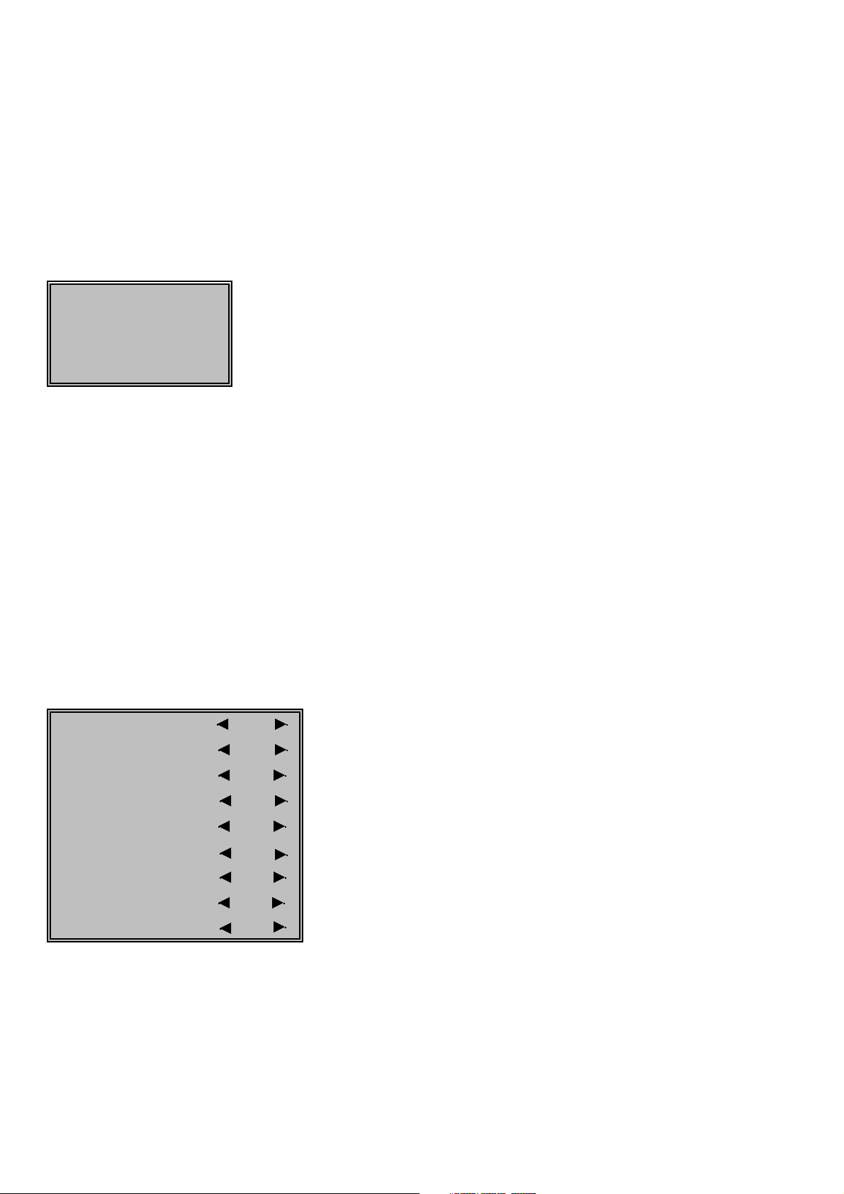
Factory Menu
Source SCART shows the current input mode
ADC ADJ to access the ADC auto calibration menu
Picture Mode to access the picture preset adjustment menu
Colour Temp to access the white balance adjustment menu
TTX Brightness to access the text brightness preset level adjustment menu
Other to access other availible adjustment options
Model B/S to select the model characteristics (betting shop or CCTV)
Factory Reset to perform a memory reset to restore default values
Version : 1.01 indicates the current software version loaded
05 / 07 / 08 indicates the issue date of the software version
Model Option:
B/S (Betting shop) For models fitted with SCART & TUNER
CCTV (Closed circuit TV) For models fitted with BNC in & out
Also some menu's & options will not be accessible in the CCTV mode.
Use P+ / P- on the remote to highlight the desired item, then use Vol + to enter or change the item.
With the set turned ON, press the following sequence of buttons on the remote control:-
The main service menu will be displayed on screen.
Changing the model option will automatically alter some of the settings to suit
the requirements of the application.
N4FB
Page 4
4
Hotel Menu
Hotel
Hotel Mode Off Turn ON to disable RF channel tuning facility
Volume Max 100 set value between 0 and 100 to limit the sound output availible from speaker
On Program SCART set the desired input or channel that will appear at switch on
Use P+ / P- to select item and Vol+ / Vol- to change data.
To enter the Hotel Menu press & hold the GREEN button on the remote for about 5 seconds,
the Hotel menu will appear at the bottom of the screen.
Hotel mode allows the owner to restrict the functionality of the set so that the user may not tamper
Volume max' allows the owner to set a limit to the maximum sound output to prevent noise disturbance.
with settings such as channel tuning.
Option Menu
This menu is used to enable or disable certain functions availible in the bios.
To enter the Option menu press and hold the GREEN button on the remote for about 5 secs, first the
HOTEL menu will appear. Now press and hold GREEN for a further 5 secs, now the OPTION menu
will appear. Only the highlighted items may be accessed by the user.
Tuner option On Allows RF tuning. (not availible in CCTV mode)
Sound option Off Allows sound output to loudspeaker (if fitted)
SCART option On Allows inputs by SCART connector (not availible in CCTV mode)
BNC option Off Allows inputs by BNC connector (not availible in B/S mode)
PC option Off Allows VGA input from PC (if VGA connector fitted)
Auto shut off AV On Enables Auto shut off operation in AV mode
RGB option On Allows RGB input from SIS network via SCART (B/S model only)
Text no signal On Prevents loss of Text stability with no signal
Blue back Off Enables Blue Background operation during no signal condition.
to change the state.
Use P+ / P- on the remote to highlight the desired item, then use Vol+ / Vol-
N4FB
Page 5

5
Other Menu
SCART Brightness 164
Black Stretch 100
OSD Transparency Off
Gamma 2.3
TTX H Position 90
TTX V Position 0
Peaking Level : RF 18
Peaking Level : Scart 16
Peaking Level : Svideo 16
Peaking Level :RGB 18
Peaking Level : AV 16
Use P+ / P- to select item & Vol+ / Vol- to change value.
Can be used to equalise the picture peaking in SCART mode
Can be used to equalise the picture peaking in SVIDEO mode
Can be used to equalise the picture peaking in RGB mode
Can be used to equalise the picture peaking in AV mode
Allows the Gamma curve to be altered if required
Can be used to centralise the Teletext horizontally
Can be used to centralise the Teletext vertically
Can be used to equalise the picture peaking in RF mode
This menu contains some items that should not normally require adjustment.
Controls brightness of composite video inputs independantly to RGB
Used to overcome the problem of crushed dark shades
Allows the OSD to become partially or fully transparent
ADC Calibration
A test signal of RGB colour bars must be applied to the SCART input for this adjustment to be
Source SCART
R-Offset 127 It is not possible to manually adjust these values
G-Offset 127
B-Offset 127
R-Gain 127
G-Gain 127
B-Gain 127
AutoTune
Press Vol + to begin auto Calibration
The ADC ADJ menu is accessible from the main service menu.
performed. If the result is successful, OK will be displayed at the bottom of the OSD.
ADC calibration is performed automatically by pressing Vol + key whilst the ADC menu is displayed.
This adjustment is not required for the CCTV model.
N4FB
Page 6

6
Colour Temperature
Source SCART
Colour Temp Normal
R-Gain 128
G-Gain 128
B-Gain 128
R-Offset 128
G-Offset 128
B-Offset 128
Method
Use P+ / P- to select item and Vol+ / Vol- to change value.
If the Grey scale suffers from a predominant tint use the R, G, B Offset adjustment to neutralise,
in this case the white level adjustment should be re-checked.
the pictures' white balance.
If a suitable colour analyser is availible adjust the co-ordinates to X= 0.290, Y= 0.290 (+/- 0.01)
Keeping one colour constant, adjust R, G, B Gain value to achieve a pure white image.
Connect a 100% white test signal to either SCART or Aerial input and set picture mode to STANDARD
Enter the service mode & select Colour Temperature option.
Red adjustment (grey scale)
Green adjustment (grey scale)
Blue adjustment (grey scale)
The Colour Temperature menu is accessible from the main service menu and is used to adjust
Red adjustment (white level)
Green adjustment (white level)
Blue adjustment (white level)
Picture Mode
as required.
Source SCART
PIC Mode Standard
Contrast 42
Brightness 48
Colour 45
Sharpness 25
The predetermined settings for the fixed picture modes can be adjusted using this Menu.
Select the PIC Mode desired to be changed using P+ / P- and Vol+ / Vol- change the value
N4FB
Page 7

7
Text Brightness
MAX 63
MID 42
MIN 21
The three predetermined levels set for Teletext brightness control can be adjusted in this menu.
Use P+ / P- to select item & Vol+ / Vol- to change value.
Factory Reset
In certain circumstances it might be useful to restore the memory to the default conditions
preset within the system bios.
To do this enter the main factory menu and select the "Factory Reset" option.
Press vol+ to proceed with the initialisation.
This reset does not affect the ADC calibration or the White balance adjustment settings,
nor does it clear the stored RF channels.
N4FB
Page 8

8
OPTIONS & SETTINGS
The table below shows the correct factory settings for this model.
Some of these items may need to be restored if a ‘Factory Reset’ is performed.
N4FB
PIC MODE CONTROL N4FB
Standard
Contrast
42
Brightness
48
Colour
45
Sharpness
25
Movie
Contrast
36
Brightness
48
Colour
54
Sharpness
22
Vivid
Contrast
52
Brightness
48
Colour
55
Sharpness
48
User
Contrast
50
Brightness
48
Colour
50
Sharpness
49
Picture
Picture mode Standard
TXT Brightness
mid
Sound
Volume
N/A
Advance
Child Lock
Off
3D NR
Off
Colour System
Auto
TTX Language
West
OSD Setup
Language
English
Time out
15
TV Setup
Colour system
Auto
Sound system
I
AFT
On
Page 9

9
N4FB
OPTIONS & SETTINGS continued
Factory
Model B/S
Hotel
Hotel Mode Off
Volume max 100
On Program SCART
Options
Tuner option On
Sound option
Off
SCART option On
BNC option Off
PC option Off
Auto shut off AV On
RGB option On
Text no signal On
Blue Back Off
TTX Bright
Max 63
Mid 42
Min 21
Other
SCART Brightness 164
Black Stretch
100
OSD Transparency Off
Gamma 2.3
TTX H Position 90
TTX V Position 0
Peaking Level RF 18
Peaking Level Scart 16
Peaking Level Svideo 16
Peaking Level RGB 18
Peaking Level AV 16
Page 10

10
SIGNAL BLOCK DIAGRAM
N4FB
Speaker
Audio
MP7720
Amplifier
U5
Power Module
/Inverter
Backlight
LCD
panel
TTL /LVDS
U10
Video signal
RS232
Audio signal
Control signal
Input unit
process unit
Output unit
Icon explaining
U12
SDRAM
ROM
U11
sh
a
Fl
PC/Video Audio input
RS232
U3
DDC EEPROM
SCART Audio input
SCART Audio output
Tuner Audio input
2-Wire Bus
EEPROM
Loop
U9
MST96885CLD
input
CVBS input
PC Video input
SCAR-CVBS input
Tuner Video input
SCART-S-VIDEO
SCART-RGB/SIS input
Video Switch
CVBS input
U1
SIS CVBS input
Hotel-IR
GPIO
GPIO
ADC+
&LED
IR Sensor
User
Keypad
ISP
CN11
PC (VGA)
CN3
Audio in
CN4
Tuner TU1
CN1
BNC in/out
CN2
SCART
Page 11

POWER FLOW DIAGRAM
11
N4FB
VS_TUNER
TUNER,
L1
U1,U2,
U6
VS_IF
L2
U2,U6
U20
VDD
FB25
MVDD_SW
SDRAM
U12
VDDQ
MST
96885
U
VDDM
FB26
FB23
D_A
VD
AVDD_SIF
A
AVDD_MEMPLL
PANEL VDD
FB17
+3V3A_SW
FB19
FB18
VDDC
AVDDA
VDDP
AVDD_MPLL
TCON_+3V3 15” LCD
PANEL VDD
U16
+8VA +5VA -5VA
U17 U18
+5V_SW
Q29
+5V
Q30
er
rt
e
U14,
Q28
VIN_+12V
15” Inv
42
FB27,
FB
+12V_IN
6
PIN1,2
PIN5,
PWRIN
E
S
U
F
U19
FB21
1V2
+
1
2
U
FB20
+3V3
U15
FB24
FB22
,
H
IG
H
_
L
PUL
U4
MP
11
U
1
Q1
HIGH,
_
L
L
PU
U9,U3
A
MP7720
AUDIO
12V
_
MP_
A
Q19
TCON_5V 20” LCD
L
_PANE
V
+5
FB28 Q38 FB7
+5V_IN
DC JACK
CN13
Page 12

-12-
CABINET PARTS LIST FOR MODEL CE20LM5
1
3
5
CE20LM5
CABINET PARTS
610 338 9479 CABINET FRONT-N4FK
665 001 3476 DEC SHEET
610 338 8731 CABINET BACK N4FK
665 001 2646 DEC SHEET
3 665 000 6638 STAND BASE-N4EJ
4 610 338 8748 CHASSIS BASE N4FJ
5 610 329 2069 HOLDER PANEL N4EJ
ACCESSORIES
6 665 001 4343 QUICK GUIDE N4FB
SCREWS
BACK COVER 411 194 0101 x 4
STAND BASE 411 194 0101 x 2
2
Item Part No. Description Item Part No. Description
4
N4FB
1
2
{
{
Page 13

-13-
N4FB
A
A
A
A
CABINET DISASSEMBLY
Remove the 4 screws indicated (A)
then lift away the back cover.
Page 14

-14-
PIN DESCRIPTION OF SEMICONDUCTORS
G Diode
G Transistor/FET
G IC
FET
N4FB
● Diode
K
A
● Transistor/FET
E
C
B
C
E
E
B
C
● IC
K
A
K
A
K
K
K: Cathode
A: Anode
AA
C
E
C
E
B
B
C
B
B1
C1
CBE
C2
B2
E
C
BE
B1
C1
C2
2
B1 B2
E
Vdd
KK
C1
C2
E
B2
C2
E2 C1
B1
B2
A
B1
E1
B2
(GND)
2
Index
E1
C1
C2
E2
A
C: Collector
B: Base
E: Emitter
G
S
D
3
D: Drain
G: Gate
S: Source
S
G
D
1
3
2
Index
Index
N
1
Index
1
3
2
Index
Index
1
3
N
GND
Index
(IN)
N
3
1
(OUT)
4
5
6
21
5
4
3
2
1
Index
1
RESET
1
2
N
1
2
1
2
1
3
1
N
N
Index
Index
N
1
N
1
Page 15

-15-
PARTS DESCRIPTION AND READING IN SCHEMATIC DIAGRAM
1. The parts specification of resistors, capacitors and
coils are expressed in designated code. Please
check the parts description by the following code
table.
2. Some of transistors and diodes are indicated in
mark for the substitution of parts name. Please
check the parts name by the following code table.
3. Voltages and waveforms were taken with a video
colour bar signal(1Vp-p at 75 ohms terminated) and
controls to normal.
4. Voltages were taken with a high-impedance digital
voltmetre.
Example 2000 K
K 1000 BG
Characteristic
Example 160 E M 10
Capacitance value
Tolerance
Type
Rated voltage
Excepting electric capacitors, all
capacitance values of less than 1
are expressed in μF and more
than 1 are in pF.
Example L2 C1 4R7 K N
Tolerance
Inductance value
Manufacture code
Unique code
Mark Material
E Electrolytic
P Electrolytic (non-Polarised)
C Ceramic (temperature compensation)
K Ceramic
F Polyester
N Polypropylene
M Metalised polypropylene
H Metalised polypromylar
B Ceramic (semiconductor)
G Metalised polyester
Y Composite film
S Styrol
T Tantalum oxide solid electrolytic
U Organic semiconductive electrolyte
D Electric double layer electrolytic
Mark Tolerance
A not specified
B ±0.1
C ±0.25
D ±0.5
F±1
G±2
E ±2.5
H±3
J±5
K±0
M±20
N±30
P +100 -0
Q +30 -10
T +50 -10
U +75 -10
V +20 -10
W +100 -10
X +40 -20
Y +150 -10
Z +80 -20
Mark Tolerance (nH) Mark Tolerance (%)
C ±0.25 G ±2
D ±0.5 J ±5
S ±0.3 K ±10
A ±0.2 L ±15
M±20
Coil Reading
Capacitor Reading
Example 1/2
D J 10K B
Example 6 W K 8.2
Example 1/2 C K 1M
Resistor Reading
Characteristic
Z (Carbon fuse)
B (Non-burnable)
Resistance value
Tolerance (see below table)
Material (see below table)
Rated wattage (W)
K indicates in KΩ
M indicate in MΩ
Note: Resistor which is indicated with resistance value only are
1/6W carbon resistor. Resistor which is indicated with material, tolerance and value are 1/4W rated wattage.
Mark Material
D Carbon
N Metal film
S Oxide metal film
C Solid
G Metal glaze
W Wire wounding or cement
H Ceramic
F Fusible
Mark Tolerance
A ±0.05
B ±0.1
C ±0.25
D ±0.5
F±1
G±2
J±5
K±10
M±20
P+5-15
Z used in 0 ohm
G Material table
G Tolerance table
G Material table
G Tolerance table
Mark Type number
-- 1S1555,1S2473,1S2076,1SS133,DS442,1SS176
K 1S1555,1S2473,1S2076,DS442
L 1S1555,1S2076A,1S2471
M 1SS133,1SS176,GMA01
N 1S1555,1S2473,1S2076,1SS133,DS442,1SS176,1N4148
P 1S1555,1S2076A,1S2471,1N4148
R 1S1555,1S2076,1S2473,DS442,1N4148
AA 1S1555,1S2076,1S2473,1SS133,DS442,1SS176,1N4148,GMA01
G Diode
Mark Type number
-- 2SC536 2SC945A 2SC1815 2SC1740 2SC1740S KSC945C
A E, F, G P, Q, R O, Y, G Q, R, S Q, R, S
B E, F, G P, Q, R O, Y, G Q, R, S
D F, G P, Q Y, G Q, R, S
FF, G P G R, S
H F, G P, Q Y, G Q, R, S Y, G
I E, F, G P, Q, R O, Y, G Q, R, S Y, G
GF, G P G R, S G
AD F, G Q, R Y, GR Q, R, S
AE E, F, G Q, R O, Y, GR Q, R, S
G Transistor (NPN type)
Mark Type number
-- 2SA608 2SA564A 2SA1015 2SA933 2SA933S KSA733C
Y E, F Q, R O, Y, G Q, R
WF R Y, G R
V E, F Q, R O, Y, G Q, R Y, G
UF R Y, GR G
Z E, F Q, R O, Y, G Q, R Q, R
AB F R Y Q, R
AE E, F Q, R O, Y R
G Transistor (PNP type)
Diode/Transistor Type Reading
N4FB
Page 16

-16-
CHASSIS ELECTRICAL PARTS LIST
Product safety should be considered when a component replacement is made in any area of a receiver.
Components indicated by a mark in this parts list and the circuit diagram show components whose value have
special significance to product safety. It is particularly recommended that only parts specified on the following
parts list be used for components replacement pointed out by the mark .
Read description in the Capacitor and Resistor as follows:
CAPACITOR
CERAMIC 100P K 50V
Tolerance Symbols:
Less than 10PF
A: Not specified B: ±0.1PF C: ±0.25PF
D: ±0.5PF F: ±1PF G:±2PF
R: ±0.25-0PF S: ±0-0.25PF E: +0-1PF
More than 10PF
A: Not specified B: ±0.1% C: ±0.25%
D: ±0.5% F: ±1% G:±2%
H: ±3% J: ±5% K: ±10%
L: ±15% M: ±20% N: ±30%
P: +100-0% Q: +30-10% T: +50-10%
U: +75-10% V: +20-10% W:+100-10%
X: +40-20% Y: +150-10% Z: +80-20%
Material:
CERAMIC ............Ceramic
MT-PAPER ..........Metallized Paper
POLYESTER ......Polyester
MT-POLYEST ......Metallized Polyester
POLYPRO............Polypropylene
MT-POLYPRO ....Metallized Polypropylene
COMPO FILM......Composite film
MT-COMPO ........Metallized Composite
STYRENE............Styrene
TA-SOLID ............Tantalum Solid
AL-SOLID ............Aluminium Solid
ELECT ................Electrolytic
NP-ELECT ..........Non-polarised Electrolytic
OS-SOLID ..........Aluminium Solid with Organic Semiconductive Electrolytic
DL-ELECT ..........Double Layered Electrolytic
RESISTOR
CARBON 4.7K J A 1/4W
Rated Wattage
Performance Symbols:
A: General B: Non flammable Z: Low noise
Other: Temperature coefficient
Tolerance Symbols:
A: ±0.05% B: ±0.1% C: ±0.25% D: ±0.5%
F: ±1% G: ±2% J: ±5% K: ±10%
M: ±20% P: +5-15%
Rated value, ohms:
K: 1,000, M: 1,000,000
Material:
CARBON ............Carbon
MT-FILM ..............Metal Film
OXIDE-MT ..........Oxide Metal Film
SOLID ..................Composition
MT-GLAZE ..........Metal Glaze
WIRE WOUND ....Wire Wound
CERAMIC RES....Ceramic
FUSIBLE RES ....Fusible
Rated Voltage
Rated value: P=pico farad, U=Micro farad
Note: Parts order must contain Service Ref. No., Part No., and descriptions.
N4FB
!
!
Page 17

-17-
Main assembly part number 1AA0B10H089B0
Main unit kit part 1AV4U20C29201
RC / LED unit 1AV4U20C29202
Ref. No. Part No. Part description
CN10-A 645 033 2227 CORE, FERRITE
CN2 652 001 4978 SKT,RGB 21P (MRC-021V-13)
CN6-A 645 032 9364 CORE,FERRITE
CN6-PN 645 078 2381 FLEXI FLAT CABLE 120MM
EL901 645 090 0662 LCD(V201V1-T04)REV C2 CMO
TU1 665 001 3414 TUNER,U/V
U902 645 075 9673 UNIT,INVERTER-POWER
U902-A 610 315 1359 GASKET C-N2HE 80X13X13
W901 665 000 6911 3P AC CORD +4771 F7RAV
W901-A 665 001 2417 CWA4781 +JST 2P F7RAV
W901-B 645 020 3640 FERRITE RING
Z202 610 322 7313 SHIELD CASE CPU-B-N3AJ
Z202-A 610 315 1359 GASKET C-N2HE 80X13X13
The above parts are fitted locally and therefore availible as spares.
All other board mounted parts are not fitted locally and therefore cannot be sourced for spares.
Please order the complete assembly for repairs.
Electrical Parts
CHASSIS ELECTRICAL PARTS LIST
N4FB
!
Page 18

-18-
N4FB
Page 19

-19-
N4FB
Page 20

-20-
N4FB
Sanyo Industries (UK) Ltd
Printed in UK
 Loading...