

Page 1
INSTRUCTION MANUAL CCA-BC200
Rear View Back up Camera System
CAUTION
• Installation and wiring require technical expertise and experience. To ensure
proper installation and safety, consult the dealer where the product was
purchased.
SANYO’S HELP-LINE
Call the toll-free number below if you have any difficulties operating this product.
1-800-421-5013 (Weekdays 7:30 AM – 5:00 PM, Pacific Time)
Page 2
‑1‑
Page 3
CONTENTS
SAFETY PRECAUTIONS···································································································· 2
SPECIFICATION ················································································································· 4
BEFORE USING THE REAR VIEW BACK UP CAMERA SYSTEM···································· 5
ACCESSORIES AND HARDWARE ···················································································· 6
REAR VIEW BACK UP CAMERA SYSTEM OUTLINE ······················································· 7
CAUTIONS FOR CONNECTION ························································································ 8
CONNECTION ···················································································································· 9
BEFORE INSTALLATION ·································································································10
INSTALLATION ················································································································· 12
CABLE ROUTING ············································································································· 15
GUIDE LINE ADJUSTMENT AFTER REAR VIEW CAMERA INSTALLATION················· 17
REAR VIEW CAMERA DISPLAY AND SWITCHING DISPLAY MODES·························· 23
SAFETY PRECAUTIONS
<Safe and correct use of the product>
• Before using the rear view back up camera, read this instruction manual for proper use of the
product as directed.
• Sanyo and its suppliers are not responsible for damage or malfunction that arises from the failure
to follow the instructions in this manual. Please be aware that the manufacturer’s warranty may be
invalid if the procedures in this instruction manual are not followed properly.
• After using this instruction manual, store it in a place where it can be easily located.
WARNING
CAUTION
A WARNING indicates a situation in which serious injury
or death could result if the warning is ignored.
A CAUTION indicates a situation in which bodily injury
or damage to objects, or both, could result if the caution
is ignored.
WARNING
• Be sure to disconnect the negative battery terminal when wiring.
Electrocution or injury due to a short circuit could occur.
• This Rear View Back up Camera System is for exclusive use with DC 12V, negative ground
vehicles. Do not use this Rear View Back up Camera System on DC 24V vehicles (such as trucks,
buses). A fire or other damage could occur.
• Do not install this Rear View Back up Camera System in a location that blocks the rear view, or
obstructs the operation of the steering wheel, shift selector lever, or brake pedal when driving, or
jeopardizes the safety of other passengers. Otherwise, an accident or injury could occur.
−2−
Page 4

• When installing this Rear View Back up Camera System to a vehicle equipped with air bags
(The name differs depending on the manufacturer, such as SRS dual air bag, SRS side air bag,
SRS curtain air bag), do not install this Rear View Back up Camera System or route its wiring
where it affects operation of the air bag system. If the air bags do not operate properly in an
emergency, an accident or injury can occur. (Consult the dealer where the product was
purchased to determine the installation position, keeping safety in mind.)
• Do not use any cables other than ones provided with this Rear View Back up Camera System.
Do not modify the cables.
• If installing this Rear View Back up Camera System or connecting the ground using the vehicle
nuts and bolts, never use nuts and bolts from critical parts of the vehicle such as the steering
wheel, brake system, and fuel tank. Vehicle control may become inoperative, or a fire could occur.
• When drilling holes into the vehicle body to install this Rear View Back up Camera System, check
the locations of pipes, tanks, and electrical wiring so that this Rear View Back up Camera System
will not interfere with them. Otherwise, a fire or other malfunction could occur.
• Be sure to bundle cables so that they do not obstruct driving. Loose cables which become
entangled in the steering wheel, shift selector lever, or brake pedal may cause an accident.
• Do not splice the cable to connect the power supply to other devices.
• After completing the installation and wiring, make sure the brake lights, lights, horn, turn signals,
wipers, and other electrical components operate properly. Otherwise, an accident could occur.
• Do not disassemble or modify the Rear View Back up Camera System. Disassembly prohibited.
It could result in an accident, fire, or electrocution.If foreign material has penetrated the Rear View
Back up Camera System or liquid has spilled onto it, which may produce smoke, foul odor, or
abnormal noise, discontinue use immediately and always consult the dealer where the Rear View
Back up Camera System was purchased. If the Rear View Back up Camera System continues to
be used, it could result in an accident, fire, or electrocution.
• If power to the power cable has been cut or a fuse has blown, verify that the cable has not been
shorted, and replace any blown fuses with a new fuse of the same current rating. (Ampere is
displayed on the fuse.) If a non-specified fuse is used, a fire or malfunction could occur.
• Be sure to route wiring so that it does not come into contact with heated parts. Otherwise, the wire
covering will melt and cause a short, resulting in a fire or electrocution.
• Do not use this Rear View Back up Camera System if it appears damaged such as when there is
no display or sound output. Otherwise, it could result in an accident, fire, or electrocution.
• Do not touch this Rear View Back up Camera System during extreme weather conditions such as
thunder and lightning. Otherwise, it could result in electrocution.
CAUTION
• Installation and wiring requires technical expertise/experience. To ensure safety, consult the dealer
where the Rear View Back up Camera System was purchased.
• Be sure to use the Rear View Back up Camera System in the specified manner. If a non-specified
part is used, the internal parts of the Rear View Back up Camera System can be damaged or
detach because of improper attachment, resulting in an accident.
• Do not install the ECU box to a location where rain, moisture, or dust can penetrate. If water,
moisture, or dust penetrates the ECU box, it may cause fire or smoke.
• Do not install the ECU box where heat is retained such as under a carpet. Heat from the ECU box
cannot be dissipated, causing a fire, malfunction, or deterioration.
• Wire the cable so that it does not touch any metallic areas. The cable could be damaged from
contact, causing a fire or electrocution.
−3−
Page 5

• Route wiring properly according to the instructions. An incorrect connection might cause a fire or
accident.
• Be careful and prevent the wiring harness from being pinched between the vehicle body, screws,
or moving parts such as the seat rails. It could cause an accident, electrocution, or fire due to an
open or short circuit.
• The Rear View Back up Camera System is for in-car use only and is not to be used outside of the
vehicle. If it is used outside of the vehicle it could result in electrocution or other injury.
• Install the camera on the vehicle during sunny, daytime hours. If installed in rainy or foggy
weather, high humidity will weaken the adhesion strength of the double-sided adhesive tape, and
the camera may fall off, resulting in an accident or injury.
• Avoid moisture such as water, rain, fog, snow or applying excessive force to the camera for 24
hours after installation. The adhesion strength of the double-sided adhesive tape will weaken and
the camera may fall off, resulting in an accident or injury.
• Be careful when handling the double-sided adhesive tape. Touching the sticky surface of the tape
or re-attaching the bracket weakens the adhesion strength. The bracket may fall off, resulting in
an accident or injury.
• This Rear View Back up Camera System has been designed to assist the driver in confirming the
rear view when backing up the vehicle into a garage or when parallel parking. For safety reasons,
it is important for the driver to take extra precautions when backing up.
• Power Supply························································DC 12 V (DC 11 V to DC 16 V) Negative ground
• Max. Consumption Ampere ····················································································· Approx. 300mA
• Viewing System ····································································· Mirror Image*
• Imaging Device········································································································· Color CCD, ¼”
• Number of Pixels ···············································Total: 270 K pixels. Effective: Approx. 250 K pixels
• Viewing Angle ······························· Horizontal: Approx. 135 degrees, Vertical: Approx. 105 degrees
• Min. Required luminance····························································································Approx. 1.6 lx
• Output Signal··································································1Vp-p (75 ohm, NTSC), RCA-type socket
• Operation Temperature····························································································· -4°F to +140°F
• Storage Temperature ······························································································ -22°F to +176°F
• Camera Dimensions ···················································· W1.1” x H0.9” x D1.0” (without protrusions)
• ECU Dimensions ························································· W3.4” x H1.1” x D2.6” (without protrusions)
• Camera Weight·············································································Approx. 0.35lbs (including cable)
• ECU Weight·············································································································Approx. 0.37lbs
*Mirror image: The camera produces an image on the screen with the left and right appearing
reversed the same as when looking into the rear view mirror or the door mirrors.
• Specifications may change at any time without prior notification.
SPECIFICATION
(for vehicle reversing)
(Standard rear view is displayed)
−4−
Page 6

BEFORE USING THE REAR VIEW
BACK UP CAMERA SYSTEM
Regarding methods of use
• The Rear View Back up Camera System is a devise designed only to assist the driver. The driver
must take full precautions to confirm the safety and conditions around the vehicle.
• Water droplets on the camera lens could adversely affect the image.
• The positioning appearing on the screen changes according to the vehicle conditions (number of
occupants and weight of cargo). Always directly confirm the safety of the rear of the vehicle and
its surroundings visually while operating the vehicle.
• Never reverse the vehicle while looking only at the image appearing on the screen. Always
confirm the safety of the rear of the vehicle and its surrounding by using both the rear view mirror
and the door mirrors in combination with the rear view camera.
• The actual position and distance of persons or objects appearing on the screen may differ
depending on the properties of the camera lens.
Regarding use
• Do not knock the camera or allow it to be hit forcefully by an object. Otherwise, it could result in
the camera being damaged.
• Exposing the camera lens to extreme temperature change via a direct flame, hot drier or hot water
could break or damage the camera lens.
• Do not allow the camera lens to capture images of direct sunlight for long periods of time.
Otherwise it could leave permanent impressions on the screen.
• The screen image could distort at the moment the rear view image is displayed (differs depending
on the monitor model connected to the system). The image will stabilize soon afterwards.
• If the system is used for a long period of time, white streaks and lines will appear due to increased
temperature, however, because of the CCD properties the system will not be damaged.
• Screen flicker may occur while in fluorescent-lit areas utilizing 50 Hz power supplies, however, this
will not cause damage to the system.
• Do not wipe the camera unit and lens area, installation bracket, or camera cable with volatile
chemicals or cleaning agents containing alcohol, benzene, thinner, or gasoline. Use of these
chemicals or cleaners will cause deformation, deterioration or damage to the system.
• Do not wipe any part of the system with cleaners containing polishing or abrasion agents as they
will cause scratching.
• If the lens becomes soiled, wipe lightly with a soft, clean cloth soaked in water. Wiping with
excessive force using a dry cloth could cause scratching.
• Do not scratch or nick the camera cable. Water or moisture penetrating the camera via a crack or
opening in the camera could cause electrocution, fire, or other irreparable damage.
• If the vehicle is to be washed with the camera installed, avoid water directly contacting the cable
area to prevent water from penetrating into the vehicle cabin.
• Do not allow highly pressurized water from automatic car washing machines or high-pressure car
washers to contact the camera unit. Otherwise, the camera could fall off, or water could penetrate
the camera unit due to an inability to maintain a waterproof seal, which could result in
electrocution, fire, or other irreparable damage.
• Inspect the camera and cables periodically. Verify that the installation screws have not become
loose, or the installation bracket is not separating from the installation surface. Tighten any loose
screws. If the camera falls off and hits a pedestrian it could result in an accident or injury.
• If direct sunlight or strong light (sunlight reflected from the bumper, or headlights) is directed at the
camera lens, it could cause fluctuations in the light source and vertical lines (streaks) to appear on
the screen, however, this does not indicate a malfunction or damage.
−5−
Page 7
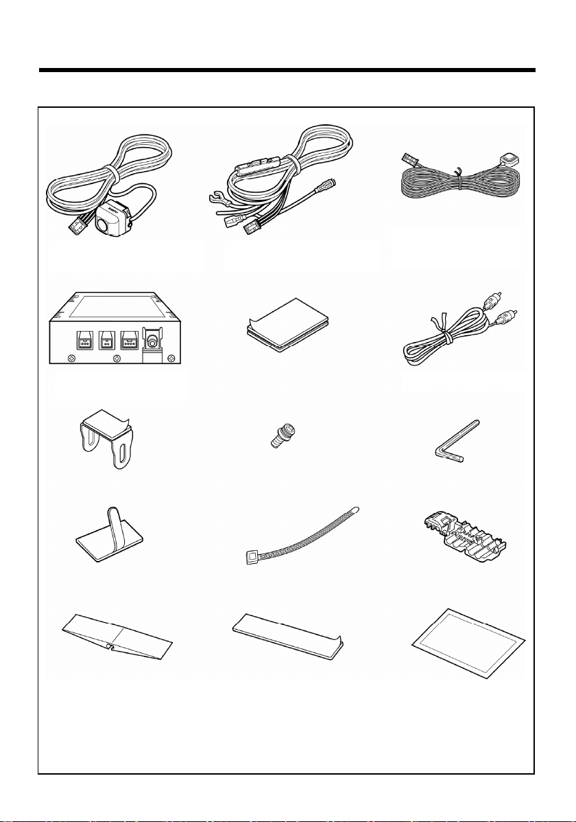
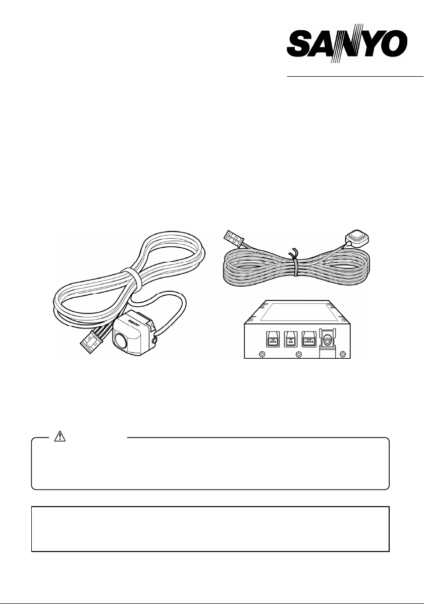
ACCESSORIES AND HARDWARE
Make sure all the following parts are included in the Rear View Back up Camera System kit.
1
Rear view camera………1 pc.
(with approx. 26.2 ft. long cable)
ECU box…….........….1 pc.
(Electronic Control Unit box)
Bracket (for camera)…1 pc.
(with double sided tape)
Cable clamp…10 pcs.
Power supply cable……1 pc.
(approx. 4.92 ft. long, with fuse)
Hook-and-loop fastener…1 set
(for ECU box)
Screw (for camera)…2 pcs.
(Hexagon type, M3 x 6)
Cable tie……2 pcs.
Control switch cable…….1 pc.
(approx. 8.20 ft. long,
with double sided tape)
Video output cable…...1 pc.
Hexagon wrench…1 pc.
Self-lock conductor… 1 pc.
(for reverse signal detection)
Waterproof pad…1 pc.
Instruction manual… 1 pc.
(with warranty)
Double sided tape… 1 pc.
(for waterproof pad)
Alignment guide…… 1 pc.
−6−
Cleaning cloth… 1 pc.
Page 8
y
)
g
p
REAR VIEW BACK UP CAMERA
SYSTEM OUTLINE
Display mode
Including the standard rear view image captured by
the camera, a digitally corrected rear view,
view-from-top, and standard rear view can be
selected. Guide lines are indicated in order to assist
the driver and assure safety when backing up.
View-from-top height alignment
The view-from-top height can be set by alignment of the
virtual camera. (For alignment process, refer to Step 3
on page 20.)
Offset Calibration
If the camera is not installed in the center rear of the
vehicle, the offset can be corrected using the alignment
function.
Need help? Call
1-800-421-5013
Standard rear view
(Virtual camera 1)
(Deviated center)
Camera
Digitall
View-from-to
Camera
View-from-top
Standard view
Virtual camera
View-from-top
Standard rear view
corrected rear view
Left/right guide lines (Green)
(Guide lines to indicate
width of vehicle
6 ft. guide line (Light blue)
3 ft.
1.5 ft. guide line (Red)
uide line (Yellow)
Virtual camera 2
Virtual camera 1
View-from-top
(Virtual camera 2)
View-from-top
(Corrected center)
−7−
Page 9

CAUTIONS FOR CONNECTION
CAUTION
• Before connecting, disconnect the negative battery terminal. Connect the negative
battery terminal after all other connections are completed.
• Connection terminals and cables are differentiated by color. Make connections to the
same colors. Make sure connectors are securely inserted until a click sound is heard.
Incomplete connection may cause a distorted picture or operation errors.
• Before disconnecting the connector, turn the ignition switch to the off position.
Otherwise, it may cause a malfunction. When disconnecting the connector, hold the
connector itself to remove it while pressing the connector lock. If the cable is pulled, it
may come off, causing a malfunction.
• Do not splice the power supply cable to connect it to the power source of other
devices. A fire or electrocution could occur due to excess current flow on the power
cable.
• Always connect the red lead wire of the power supply cable to the accessory (ACC)
power supply.
* Do not connect this Rear View Back up Camera to the power supply for the camera,
which some navigation systems are equipped with.
• Connect the brown lead wire to the signal line which switches from 0 V to 12 V when
the shift lever is shifted to R (reverse).
• If a small plug socket input monitor is used, a commercially-available adapter is
required to convert it to a pin plug. The adapter can be purchased at an electric
appliance shop.
−8−
Page 10

s
s
CONNECTION
Control switch
connection terminal
(Green)
ECU box
Rear view camera
connection terminal
(Black)
Connect the
cable according
to the color and
shape of the terminal
Connect to the reverse signal
Connect firmly to a
metal part of vehicle
(for grounding)
cable of vehicle using
self-lock conductor included
with the Rear View Back up
Camera System. Refer to
“How to use self-lock
conductor”.
Powe r su ppl y
connection terminal
(Brown)
Power supply cable
(Black)
(Brown)
Self-lock
conductor
(Brown)
(Black)
(Green)
Rear view camera
Video output
connection terminal
(Yellow)
(Yellow)
Video output cable (RCA Type)
Connect to
(Yellow)
Camera input
terminal or
video input
terminal on
navigation or
external
monitor.
witch
Connect to point
where power is
supplied at ignition
switch ACC position.
This terminal allows connection of other accessory devices. Do not remove cap/sleeve when not in use.
(Red)
Fuse(1A)
Control
witch cable
CAUTION
Control
• Installation and wiring require technical expertise and experience. To ensure proper
installation and safety, consult the dealer where the product was purchased.
Notes
• Always use the same type of fuse with the same current rating when replacing it.
• When connecting to a navigation system or an external monitor, also refer to the
manual provided with the unit.
• Depending on the type of vehicle or navigation system, the rear view back up
camera system may not function as expected. Consult the dealer where the product
was purchased.
−9−
Page 11

BEFORE INSTALLATION
Rear View Back up Camera System Installation Cautions
• Bundle cables with tape or string so that they do not obstruct driving. Cables that become
entangled in the steering wheel, shift selector lever or brake pedal could cause an accident.
• Peel off the paper backing from the tape on the camera bracket and firmly attach the bracket to
the surface of the vehicle. If the tape is not completely adhered to the surface, the camera bracket
might become loose and fall off.
• When mounting the camera onto the glass surface, make sure the rear wiper does not hit the
camera while it operates. Otherwise, the camera could be damaged or destroyed.
• Install the camera so that it does not obstruct the opening or closing of the liftgate.
• Installing the camera in a position that obstructs vision is dangerous and could cause an accident.
Install the camera so that it does not obstruct the rear view or vehicle operation, and make sure it
does not protrude beyond the sides of the vehicle.
• To assure that the camera remains firmly attached to the vehicle:
a) Do not install the rear view back up camera system outdoors in rainy or foggy weather. High
humidity will prevent the camera from firmly adhering to the vehicle.
b) If installation is required in areas of high humidity, completely dry the surface where the
camera installation bracket is to be installed.
c) If the temperature where the camera installation bracket is to be installed is low (68°F or
lower), warm the location with a hair dryer so that the tape will adhere firmly to the surface. Do
not apply heat to the camera or the lens.
d) Do not install on a vehicle body or glass window with a surface that has been processed with
a fluorine resin coating.
• The vehicle can be driven immediately after installation as long as the following DO NOT occur
within a 24-hour period:
a) Water is poured on the vehicle surface.
b) The vehicle is driven in the rain.
c) Pulling or excessive force is applied to the camera.
Notes
• Temporarily hook up the system, confirm that the system functions properly, and
then install it permanently.
• If the system does not function properly, re-check the connections.
−10−
Page 12

Determination of Camera Installation Position (example)
• Temporarily adhering the camera with the tape, locate a suitable installation position by adjusting
the camera angle so that the rear of the vehicle (bumper and other areas) is visible in the monitor.
• Install the camera in a position that does not allow the illumination of a high-mount brake light to
reflect into the camera lens.
• Make sure the camera does not contact or rub against the vehicle body when the rear door opens
or closes.
• Removing and re-adhering the bracket will weaken the adhesion strength.
• Position the camera so that it is not aimed directly at the headlights of rear-oncoming vehicles.
The recommended installation area is shown below:
Installing the camera outside of this area could result in reduced camera functionality and reduced
rear-view visibility.
• Installing the camera on the rear spoiler or liftgate. (example)
Recommended
camera installation area
Center of vehicle
Need help? Call
1-800-421-5013
15.7 in
9.8 in
15.7 in
70.9 in
29.5 in
9.8 in
<Rear spoiler> <Liftgate>
Camera
Camera
Note
• The camera can also be installed in the taillight/license plate area or on the rear window.
< Taillight/license plate area >
Camera
< Rear window >
Camera
−11−
Page 13

INSTALLATION
Installing system on rear spoiler
1. Clean the location where the camera is to be installed.
Wipe off oil, wax, moisture, dirt and dust using a
cleaner and a clean cloth.
2. Peel off the paper backing from the tape on the camera
bracket and firmly attach the bracket to a flat surface on
the rear spoiler.
Press the bracket with a finger to assure good contact of
the bracket to the surface of the vehicle. Touching the
sticky surface of the tape with a finger or re-adhering the
bracket will weaken the adhesion strength and result in a
loose installation that could eventually fall off.
• If the temperature where the camera bracket is to be installed is low, warm the area with a hair
dryer so that the tape adheres firmly to the surface. Do not apply heat to the camera or the lens.
CAUTION
• Mount the camera level with the
vehicle and ground surface.
• Position the lens axis of the camera
square to the vehicle in order to
obtain a correct rear view.
Bracket
3. Install the camera to the bracket using the screws.
OK
Install the camera (SANYO logo facing upward)
using the hexagon wrench included in the product
package.
NG
Need help? Call
1-800-421-5013
−12−
OK
Camera mounting screw
NG
Bracket
Camera
Page 14

4. Adjust the camera angle so that the extreme rear
end of the vehicle (bumper, rear window, and
liftgate.) is displayed at the bottom of the monitor.
• After adjusting the angle, tighten the screws
with them seated at the lower end of the
oblong holes in the bracket on each side.
5. Locate a position to install the ECU box where all
6. Peel off the paper backing from the Hook-and-loop
• There are separate surfaces for each piece
CAUTION
• Verify the tightness of the screws and tighten them more if necessary.
CAUTION
• After installing the camera, the screen displays
an approximate 135-degree view between the
left and right, and an approximate 105-degree
view between up and down. The rear view back
up camera system is a device designed only to
assist the driver. The driver must take full
precautions to confirm the safety and conditions
around the vehicle.
the cables are within connection reach.
CAUTION
• Avoid installing near the ventilators for the
heater.
fastener (1 set.), adhere each piece to the bottom of
the ECU box, and install the ECU box in the
position determined in Step 5.
Note
of Hook-and-loop fastener. Attach the rough
surface to the bottom of the ECU box, and
the soft surface to the location where the
ECU box is to be installed.
• If the rough surface of the Hook-and-loop fastener
attached to the bottom of the ECU box adheres to
floor without need for the mating piece, attach the
ECU box directly to the vehicle floor without using
the mating piece.
Need help? Call
1-800-421-5013
Loosen
Approx. 135°
Hook-and-loop
(Rough side)
Extreme rear end of vehicle
Tighten
ECU box
ECU box
fastener
(bumper etc.)
Hook-and-loop
fastener (Soft side)
Floor
Approx.
105°
−13−
Page 15

7. Install the control switch in a position where it is
easy to operate.
Peel off the paper backing on the back of the control
switch and attach it to a suitable position.
CAUTION
• Do not install the control switch in a
position that obstructs vehicle operation.
Control switch
How to use self-lock conductor
1. Insert the reverse signal cable of the vehicle into the
self-lock conductor.
2. Fold the self-lock conductor and lock the reverse
signal cable.
3. Insert the reverse signal pick-up cable (Brown)
included with the system into the self-lock
conductor.
*Insert the cable until it stops.
4. Close the self-lock cover and firmly lock it by
pinching it with pliers.
Need help? Call
1-800-421-5013
Vehicle reverse signal cable
Cable stopper
Reverse signal pick-up
cable included with
system (Brown)
−14−
Page 16

CABLE ROUTING
The following is an example when installing the camera on the rear spoiler.
Control switch
• Route the cable so that it does not block or obstruct vehicle operation.
• Route the rear view camera cable as far away from the vehicle antenna as
• Clean the areas where the cable clamps and waterproof pad are to be attached.
1. Route the camera cable along the top of the liftgate
CAUTION
possible to prevent noise interference with AM radio band reception. Also, route
the cable as far as possible from a TV antenna, if equipped.
Wipe out oil, wax, moisture, dirt and dust with a cleaner and a clean cloth.
and secure the cable with the cable clamps included
with the Rear View Back up Camera System.
Straighten the cable along the top of the spoiler (or
liftgate) and insert it through the opening at the side
of the liftgate.
• Give the cable some slack to enable smooth
opening and closing of the liftgate.
2. Route the camera cable down to the lower part of
the liftgate and secure it with the cable clamps.
Route the cable to the outside of the liftgate hinge
and harness cover.
• Route the cable carefully so that the cable is not
pinched when the door opens and closes.
• Route the cable carefully to prevent water
penetration.
Need help? Call
1-800-421-5013
Camera
ECU box
Cable clamp
Camera
Cable
clamp
Harness cover
Hinge
Cable clamp
Cable clamp
Cable clamp
Cable tie
−15−
Page 17

3. Route the camera cable to the ECU box positioned
inside the vehicle and clamp it using the cable
clamps.
Insert the cable into the slit provided in the
waterproof pad and attach the waterproof pad to
the weather strip on the vehicle at the point where
the cable enters the vehicle.
4. Route the control switch cable to the ECU box and
secure it with cable clamps.
CAUTION
• Route the cable so that it does not obstruct
vehicle operation.
•
Confirmation of camera installation and
cable routing
Make sure the camera and cable do not interfere
when operating the liftgate, and that the cable does
not contact the edge of the liftgate.
• Connecting Video Cable
Connect the video output cable to the camera input
terminal or video input terminal on the navigation
system or external monitor. (Read the separate
instruction manuals for these devices to connect them
correctly.)
Need help? Call
1-800-421-5013
Luggage finish plate
Position with no ribs on the rear side
Cable clamp
0.1 in
0.1 in
Weather strip
Control switch
Liftgate
ECU box
Video output connection
terminal (Yellow)
Video output
cable (Yellow)
(Yellow)
To Video input terminal
Connect to camera input terminal or
video input terminal on navigation
system or external monitor
Waterproof pad
ECU box
Camera
Cable
Navigation system
or external monitor
−16−
Page 18

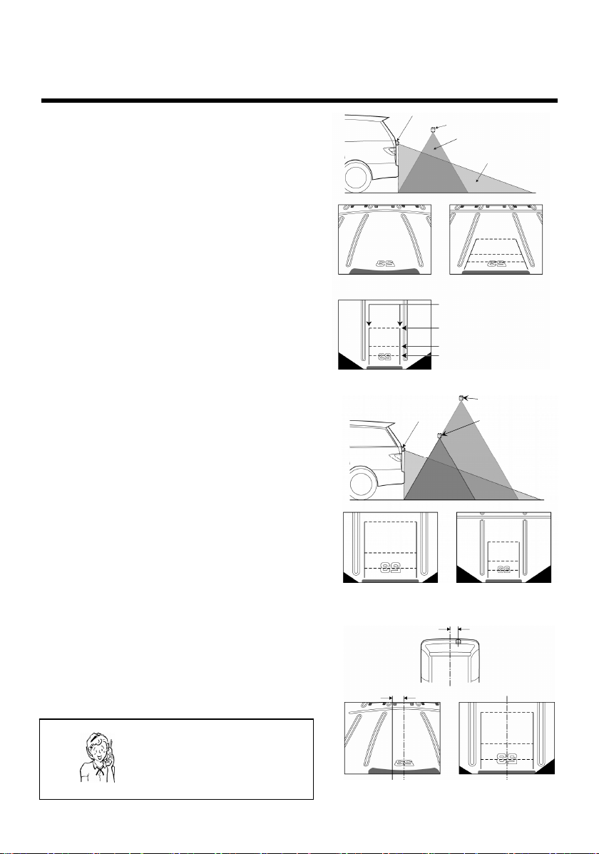
GUIDE LINE ADJUSTMENT
AFTER REAR VIEW CAMERA INSTALLATION
The guide lines on the screen need to be aligned with the image taken from the rear view camera (and
other reference items) so that the system is correctly matched to the vehicle.
There are seven reference items to align including,
(1) View-from-top angle alignment
(2) Center-line alignment
(3) View-from-top height alignment
(4) Left/right guide lines alignment
(5) Right guide line alignment
(6) 3 ft. guide line alignment
(7) 1.5 ft. guide line alignment
During the alignment process, the screen automatically changes to the view-from-top and all the
alignment parameters are automatically reflected in the digitally corrected rear view.
• Install the Rear View Back up Camera system in a safe place away from other
Preparation before performing alignment procedure
The following auxiliary items are required for alignment. Prepare them in advance.
1. Locate an area with parallel lines painted on a
2. Prepare markers to indicate the center line of the
3. Prepare two markers to indicate the width of the
4. Ruler to measure 1.5 ft. and 3 ft., and two markers.
• Cans or bottles make good markers.(Marking tape
Park the vehicle parallel to the parking space lines and
place markers shown in the right figure:
CAUTION
vehicles and pedestrians. Set the emergency brake and block the wheels so that
the vehicle does not move while aligning the system. If the vehicle deviates and
the alignment is done incorrectly, it could result in an accident.
tarmac or similar flat surface such as a parking lot.
vehicle.
vehicle.
for alignment is provided with this Rear View Back
up Camera System to indicate 1.5 ft. and 3 ft. guide
lines, and the width of the vehicle.)
6 ft.
3 ft.
1.5 ft.
Side Mirror
Markers to indicate width of vehicle
Center marker
3 ft. marker
1.5 ft. marker
Need help? Call
1-800-421-5013
−17−
Page 19

Alignment Mode
Turn the ignition switch to the ACC ON position while
depressing the control switch.
Seven rectangles at top left indicate
seven items to align
• Press and hold the control switch until the screen
appears.
View-from-top alignment screen appears.
(Seven rectangles at top left indicate seven items to
align.)
If adjustment mode cannot be selected
1. Turn the ignition switch to the ACC ON position while pressing the switch. Press and hold the
switch for two seconds or more.
2. Turn the monitor on so that rear view images captured by the camera can be seen.
• If any view is not displayed on the screen, turn the ignition switch to the ON position (without
starting the engine) and set the shift lever to R (reverse).
• Depending on the navigation system or external monitor connected to this accessory, the
operation can be interlocked with the reverse gear.
• If the vehicle is left with the ignition switch in the ON position for long periods of time, the
battery power could be depleted.
• If no picture appears on the screen, turn the monitor power on and change the
CAUTION
input selector so that the screen of the rear view back up camera system appears.
(Check the connection between video output terminal of ECU box and the camera
or video input terminal of the monitor.) (Refer to the manual for the monitor)
Notes
• If no alignment procedure is commenced for three minutes or longer, the system
turns the image off and the set parameters will NOT be stored.
• Do not leave the ignition switch in the ACC ON position for a long period of time as it
could deplete the battery power.
• Black triangles at the bottom on both sides appear when the display mode is set to
View-from-top. This does not indicate a malfunction. In addition, depending on the
center-line alignment position, the size of each of the triangles could differ.
Alignment
Note: Follow the alignment procedures in the indicated order from 1 to 7. Each of the below alignment
steps is indicated by a flashing rectangle corresponding to each alignment item, moving from left to
right with each rectangle having a different color.
1. View-from-top angle alignment (White)
2. Center-line alignment (Red)
3. View-from-top height alignment (Violet)
4. Left/right guide lines alignment (Yellow)
5. Right guide line alignment (Green)
6. 3 ft. guide line alignment (Light Blue)
7. 1.5 ft. guide line alignment (Blue)
−18−
Need help? Call
1-800-421-5013
Page 20

1. View-from-top angle alignment (flashing white rectangle)
1-1. Each time the control switch is pressed, the
angle increases. Continuously pressing the
control switch returns the alignment to the
original angle.
Set the parking space lines parallel to the
lines on the screen.
1-2. Press and hold the control switch for more
than two seconds.
The view-from-top angle alignment is now set
and the screen changes to the center-line
alignment setting. The center guide line is
shown in red on the screen.
2. Center-line alignment (flashing red rectangle)
2-1. Each time the control switch is pressed, the
screen moves to the right. Continuously
pressing the control switch returns the
screen to the left.
Align the center guide line with the center
markers.
2-2. Press and hold the control switch for more
than two seconds.
The center-line alignment is now set and
the screen changes to the view-from-top
height alignment setting.
−19−
Page 21

3. View-from-top height alignment (flashing violet rectangle)
3-1. Press the control switch to change to a
higher or lower view-from-top.
Select a view-from-top height so that the
markers indicating the width of the vehicle
can be seen better on the screen.
3-2. Press and hold the control switch for more
than two seconds.
The view-from-top height alignment is now
set and the screen changes to the left/right
guide lines alignment setting. Left/right guide
lines are indicated in red on the screen.
4. Left/right guide lines alignment (flashing yellow rectangle)
4-1. Each time the control switch is pressed, the
width of the guide lines becomes narrower.
Continuously pressing the control switch
sets the screen at the maximum width.
Set the left guide line to match the left-side
marker of the vehicle.
4-2. Press and hold the control switch for more than
two seconds.
The left/right guide lines alignment is now set
and the screen changes to the right guide line
alignment setting. The right guide line is
indicated in red on the screen.
−20−
Page 22

5. Right guide line alignment (flashing green rectangle)
5-1. Each time the control switch is pressed, the
right guide line moves towards the center.
Continuously pressing the control switch
moves the guide line to its maximum right
position.
Set the right guide line to match the right-side
marker of the vehicle.
5-2. Press and hold the control switch for more
than two seconds.
The right guide line alignment is now set and
the screen changes to the 3 ft. guide line
alignment setting. The 3 ft. guide line is
indicated in red on the screen.
6. 3 ft. guide line alignment (flashing light-blue rectangle)
6-1. Each time the control switch is pressed, the
3 ft. guide line moves farther from the
vehicle.
Continuously pressing the control switch
moves the line farther away until it exceeds
a certain range and the line returns to the
position closest to the vehicle.
Set the 3 ft. guide line to match the 3 ft.
marker.
6-2. Press and hold the control switch for more
than two seconds.
The 3 ft. guide line alignment is now set and
the screen changes to the 1.5 ft. guide line
alignment setting. The 1.5 ft. guide line is
indicated in red on the screen.
−21−
Page 23

7. 1.5 ft. guide line alignment (flashing blue rectangle)
7-1. Each time the control switch is pressed, the
1.5 ft. guide line moves farther from the
vehicle. Continuously pressing the control
switch moves the line farther away until it
exceeds a certain range and the line
returns to the position closest to the vehicle.
Set the1.5 ft. guide line to match the 1.5 ft.
marker.
7-2. Press and hold the control switch for more
than two seconds.
The 1.5 ft. guide line alignment is now set and
also 6 ft. guide line alignment is now set
automatically and all the alignment settings
are now completed.
The screen will disappear after displaying
the view-from-top for three seconds.
Note
• The 6 ft. guide line may not display as a
result of camera installation conditions.
8. After turning the ignition switch off and removing the auxiliary items used for alignment, move the
vehicle to a safe place.
−22−
Page 24

REAR VIEW BACK UP CAMERA DISPLAY
AND SWITCHING DISPLAY MODES
Preparation prior to use
Make sure the ignition switch is in the ON or ACC position.
1. Turn the monitor on and select the input mode
2. Set the selector shift lever to R (reverse).
3. Press the control switch to change the display mode.
CAUTION
• If the image turns off automatically after the guide line alignment, turn the ignition
switch off, then to the ACC ON or ON position prior to the following procedure.
switch to view the image from the rear view camera
on the screen. (Refer to the instruction manual for
the monitor for details.)
A digitally corrected rear view will be visible on the
screen.
Digitally corrected rear view View-from-top Standard view
CAUTION
• The rear view back up camera system is a devise designed only to assist the
driver. The driver remains responsible for being aware of and confirming the
vehicle surroundings. For safety reasons, it is important for the driver to take
extra precautions when backing up.
Notes
• After the ignition switch is turned from off to the ACC ON or ON position, a digitally
corrected rear view is displayed on the screen first.
• When changing the display mode, the selected display mode remains until the
ignition switch is turned off.
• The rear view of the vehicle is not displayed while the vehicle is not in reverse.
Need help? Call
1-800-421-5013
−23−
 Loading...