

SANYO 2SC3361, 2SA1331 Datasheet
Ordering number:EN3217
PNP/NPN Epitaxial Planar Silicon Transistors
2SA1331/2SC3361
High-Speed Switching Applications
Features
· Fast switching speed.
· High breakdown voltage.
· Small-sized package permitting the 2SA1331/
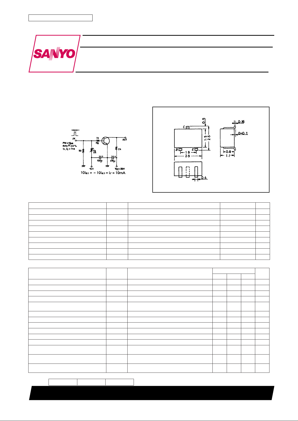
Package Dimensions
unit:mm
2018A
2SC3361-applied sets to be made small and slim.
Switching Time T est Circuit
( ) : 2SA1331
(For PNP, the polarity is reversed)
Unit (resistance : Ω, capacitance : F)
Specifications
Absolute Maximum Ratings at Ta = 25˚C
retemaraPlobmySsnoitidnoCsgnitaRtinU
egatloVesaB-ot-rotcelloCV
egatloVrettimE-ot-rotcelloCV
egatloVesaB-ot-rettimEV
tnerruCrotcelloCI
)esluP(tnerruCrotcelloCI
tnerruCesaBI
noitapissiDrotcelloCP
erutarepmeTnoitcnuJjT 521
erutarepmeTegarotSgtsT 521+ot55–
Electrical Characteristics at Ta = 25˚C
retemaraPlobmySsnoitidnoC
tnerruCffotuCrotcelloCI
tnerruCffotuCrettimEI
niaGtnerruCCD
tcudorPhtdiwdnaB-niaGf
ecnaticapaCtuptuOesaBnommoCC
egatloVnoitarutaSrettimE-ot-rotcelloCV
egatloVnoitarutaSrettimE-ot-esaBV
egatloVnwodkaerBesaB-ot-rotcelloCV
egatloVnwodkaerBrettimE-ot-rotcelloCV
egatloVnwodkaerBesaB-ot-rettimEV
emiTyaleDt
emiTesiRt
emiTegarotSt
emiTllaFt
* : The 2SA1331/2SC3361 are classified by 1mA hFE as follows :
08140907255310046002
OBC
OEC
OBE
C
PC
B
C
V
OBC
OBE
h
EF
T
bo
d
r
gts
f
BC
V
BE
V
EC
V
EC
V
BC
I
)tas(EC
C
I
)tas(EB
C
I
OBC)RB(
C
I
OEC)RB(
C
I
OBE)RB(
E
I,V04)–(=
0=1.0)–(Aµ
E
I,V4)–(=
0=1.0)–(Aµ
C
I,V6)–(=
Am1)–(=*09*004
C
I,V6)–(=
Am1)–(=001zHM
C
zHM1=f,V6)–(=)5.3(
I,Am01)–(=
Am1)–(=1.0)–(4.0)–(V
B
I,Am01)–(=
Am1)–(=57.0)–(1.1)–(V
B
I,Aµ01)–(=
0=06)–(V
E
R,Am1)–(=
=∞ 05)–(V
EB
I,Aµ01)–(=
0=5)–(V
C
tiucriCtseTdeificepseeS04sn
tiucriCtseTdeificepseeS)021(
tiucriCtseTdeificepseeS)091(
tiucriCtseTdeificepseeS)002(
Marking 2SA1331 : O, 2SC3361 : S
hFE rank : 4, 5, 6
[2SA1331/2SC3361]
nimpytxam
C : Collector
B : Base
E : Emitter
SANY O : CP
sgnitaR
7.2
08
032
061
06)–(V
05)–(V
5)–(V
051)–(Am
004)–(Am
04)–(Am
051Wm
˚C
˚C
tinU
Fp
sn
sn
sn
SANYO Electric Co.,Ltd. Semiconductor Bussiness Headquaters
TOKYO OFFICE Tokyo Bldg., 1-10, 1 Chome, Ueno, Taito-ku, TOKYO, 110-8534 JAPAN
71598HA (KT)/7139MO, TS No.3217-1/4
2SA1331/2SC3361
No.3217-2/4
 Loading...