


VG6000
This equipment has been tested in accordance with the requirements contained in the appropriate Commission regulations. To the best of our knowledge, these tests were performed using measurement procedures consistent with industry or Commission standards and demonstrate that the equipment complies with the appropriate standards. Each unit manufactured, imported or marketed, as defined in the Commission's regulations, will conform to the sample(s) tested within the variations that can be expected due to quality production and testing on a statistical basis.
We further certify that the necessary measurements were made by Kansai Electronic Industry Development Center, Ikoma Emission Measurement Station, 10830, TakayamaCho, Ikoma-City, Nara, 630-01 Japan.
Page 1

VG6000
TABLE OF CONTENTS
Page #
2Table of Contents
3Radio Control System and Specifications
4Academy of Model Aeronautics / Initial Preparation
5Transmitter Features
6Airborne System Connections / NiCd Charging Infomation
7Airborne Components / Warning Alarms
8Transmitter Battery Removal / Stick Length Adjustment
9Transmitter Stick Tension Adjustment
10Trainer System
11Microprocessor / Bar Graph Voltage Indicator
12Features Descriptions
13Stick and Switch Functions
14Dual Rates / Exponential
15End Point Adjustment / Servo Centering
16Servo Reversing / V-Tail Mixing
17Delta Wing / Flaperons
18Flaperons CONTINUED / Differential
19Flap to Elevator Mixing / Aileron to Rudder Mixing
20Model Select / Elevator to Flap Mixing
21Throttle Cut / Count Down Timer
22Sound Click / Battery Voltage Display
23Model Settings
Page 2

VG6000
RADIO CONTROL SYSTEM
Thank you for selecting the Airtronics VG6000 Radio System. In designing the VG6000 we have made every effort to provide you with a radio that will allow you to extract the maximum performance from your powered aircraft, or sailplane, while at the same time simplifying the task of setting up and adjusting your model. These instructions are written in great detail to help you understand what all of your VG6000 capabilities are. Flyers may find it advantageous to read all sections of the manual to become more acquainted with the operation of the VG6000 system.
Again, we appreciate your selection of an Airtronics Radio Control System and wish you many hours of flying enjoyment.
VG6000 Transmitter Specifications:
Transmitter Type: |
6 Channel, Dual Stick with propriety Microprocessor. |
Dimensions: |
W: 7.5” X H: 8.0” X D: 2.5” |
Weight: |
1 lb. 11 oz |
Power Output: |
600 mWatts |
Frequencies: |
72 MHz |
Modulation: |
PPM/FM Only |
Power Supply: |
9.6 Volt, 700 mAh NiCd |
Current Drain: |
180 MA |
Temperature Range: |
0 to160 degrees F |
Pulse Width: |
1.5 ms (nominal) |
Model Memory: |
4 |
VG6000 Receiver Specifications:
Receiver Type:
Receiver Sensitivity:
Dimensions:
Weight:
Receiver Power Supply:
92777Z PPM/FM 7 Channel, Super Narrow Band with Universal “Z” Connectors
1.5 microvolts
L: 2.20”, W: 0.06”, H: 0.82” 1.2 ounces
Four Cell, 4.8 Volt, 700 mAh NiCd
Additional Receivers that will work with the VG6000:
92515Z 5 channel FM Single Conversion receiver. (channels 11 thru 54 only)
Many older FM Airtronics receivers will work with the VG6000, check or call us to find out more.
Page 3

VG6000
ACADEMY OF MODEL AERONAUTICS
5161 East Memorial Drive
Muncie, Indiana 47302
The Academy of Model Aeronautics (AMA) is a national organization representing modelers in the United States. We urge you to examine the benefits of membership, including liability protection in the event of certain injuries. The Academy has adopted simple and sane rules which are especially pertinent for radio controlled flight as the OFFICIAL AMA NATIONAL MODEL AIRCRAFT SAFETY CODE, which we have partially reprinted below:
I will not fly my model aircraft in sanctioned events, airshows or model flying demonstrations until it has been proven to be airworthy by having been previously, successfully flight tested.
I will not fly my model higher than approximately 400 feet within 3 miles of an airport without notifying the airport operator. I will give the right-of-way and avoid flying in the proximity of full-scale aircraft. Where necessary, an observer shall be utilized to supervise flying to avoid having models fly in the proximity of full-scale aircraft.
Where established, I will abide by the safety rules for the flying site I use, and I will not willfully and deliberately fly my models in a careless, reckless and/or dangerous manner.
I will have completed a successful radio equipment ground range check before the first flight of a new or repaired model.
I will not fly my model aircraft in the presence of spectators until I become a qualified flyer, unless assisted by and experienced helper.
I will perform my initial turn after take off away from the pit or spectator areas, unless beyond my control. I will operate my model using only radio control frequencies currently allowed by the Federal Communications Commission. (See chart below) Only properly licensed amateurs are authorized to operate equipment on amateur band frequencies.
72 MHz BAND by Channel and Channel Frequency
11 |
72.010 |
21 |
72.210 |
31 |
72.410 |
41 |
72.610 |
51 |
72.810 |
12 |
72.030 |
22 |
72.230 |
32 |
72.430 |
42 |
72.630 |
52 |
72.830 |
13 |
72.050 |
23 |
72.250 |
33 |
72.450 |
43 |
72.650 |
53 |
72.850 |
14 |
72.070 |
24 |
72.270 |
34 |
72.470 |
44 |
72.670 |
54 |
72.870 |
15 |
72.090 |
25 |
72.290 |
35 |
72.490 |
45 |
72.690 |
55 |
72.890 |
16 |
72.110 |
26 |
72.310 |
36 |
72.510 |
46 |
72.710 |
56 |
72.910 |
17 |
72.130 |
27 |
72.330 |
37 |
72.530 |
47 |
72.730 |
57 |
72.930 |
18 |
72.150 |
28 |
72.350 |
38 |
72.550 |
48 |
72.750 |
58 |
72.950 |
19 |
72.170 |
29 |
72.370 |
39 |
72.570 |
49 |
72.770 |
59 |
72.970 |
20 |
72.190 |
30 |
72.390 |
40 |
72.590 |
50 |
72.790 |
60 |
72.990 |
INITIAL PREPARATION
PACKAGING:
The packaging of your Airtronics VG6000 Radio Control System has been especially designed for the safe transportation and storage of the radio’s components. After unpacking your radio, DO NOT DISCARD THE CONTAINERS! You should set the packaging aside for use if you ever need to send your radio in for service, or to store your radio in case you do not plan to use it for an extended period of time.
Page 4

VG6000
VG6000 TRANSMITTERS FEATURES
The VG6000 narrow band PPM/FM computer radio control system is designed for the use of power models and sailplanes for pilots who demand a quality product. The VG6000 is packed with all of the capabilities that the beginner as well as the more advanced modelers demand. It has the features available to get the most out of any type of model.
Program Features
Elevator and Aileron Dual Rates Elevator and Aileron Exponential End Point Adjustment all Channels Servo Centering all Channels Servo Reversing all Channels
4 Model Memory Timer
Sound Click On/Off Battery Voltage Display Throttle Cut
Training System Compatable
Transmitter Features
Large LCD Display
One Menu Format Display
Digital Trim Display
Battery Voltage Bar Graph Display
Digital Trims
Low Battery Alarm
Throttle Cut Button
Trainer Button
Dual Rate Slide Switches
3 Position Flap Switch
2 Position Retract Switch
Smooth Movement Sticks
Oragomic Curved Case
Neck Strap Holder
Mixing Capabilities
V-Tail Delta Wing Flapewron
Aileron Differensial Flap to Elevator Mixing Aileron to Rudder Mixing Elevator to Flap Mixing
Page 5

VG6000
AIRBORNE SYSTEM CONNECTIONS
NiCd Battery
|
|
Ch 6 Flap |
|
Switch Harness |
Ch 5 Gear |
|
|
|
Charge |
|
Ch 4 Rudder |
|
|
|
Connector |
|
Ch 3 Throttle |
|
|
Ch 2 Aileron |
92777/72BAND FM |
7/B |
Ch 1 Elevator |
6 |
|
|
Dual Conversion BY |
5 |
|
Narrow Band Receiver |
4 |
|
|
|
|
|
3 |
|
24 |
2 |
|
1 |
|
|
|
|
|
92777Z Receiver |
|
|
The above diagram shows how to connect the components of your VG6000 system together. At this point your objective is to get the system operating on your workbench. Once connected you must then refer to the corresponding diagram for your system showing the transmitter control stick function.
NiCd BATTERY CHARGING INFORMATION:
In order to protect the charging circuit in your VG6000 transmitter, a diode has been installed to protect it from some of the high discharge rate “cycler’s” on the market. We recommend that you charge the transmitter battery (while installed) with the supplied ATX charger, Part # 95033Z.
Should you wish to “cycle” or discharge the transmitter battery, you must first remove it from the transmitter. This allows you to bypass the protective diode.
The following two Airtronics service items will allow you to “cycle” your VG6000 transmitter battery. See your local dealer for these items.
(1) #99704 Transmitter Charging Plug with Cable for use with your cycling device (black wire w/white tracer is positive.
(1) #97051 Transmitter Battery Cycling Adapter Cable.
Above items will also work with Airtronics Quasar, Radiant, Vanguard, VG Series and all RD Series transmitter batteries.
Page 6
VG6000
AIRBORNE COMPONENTS
While your systems batteries are charging, you can familiarize yourself with the airborne portion of your radio. The airborne portion of the radio refers to any components which are mounted in your airplane and carried aloft when you fly. The airborne components consist of the receiver, which receives the signals from the transmitter, decodes them, and relays the commands to the servos. The servos which are simply electronically controlled motors used to move the controls of the plane. The NiCd battery pack which provides power for the receiver and servos to operate and the switch harness which allows you to turn the airborne package on and off.
CONNECTORS
Your VG6000 unit is equipped the new universal AIRTRONICS “Z” connectors which are color coded blue, and are electrically compatible with the receivers of other radio control system manufacturers. The connectors are rugged but should be handled with care. Note that these connectors are not compatible with older AIRTRONICS R/C equipment unless Adapter p/n 99399Z is used!
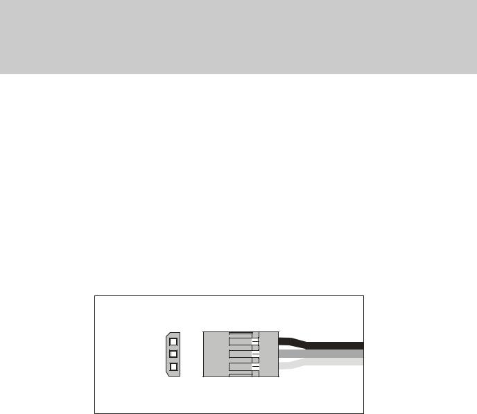
“Z” CONNECTOR
(-)Negative (+)Positive Signal
AUDIO LOW VOLTAGE ALARM
Your VG6000 transmitter is equipped with an Audio Alarm which will sound whenever the transmitter batteries drop below 9.5 volts during transmitter operation. If the alarm sounds while you are flying, land immediately and don’t operate the transmitter until it has been charged for 12 hours. The transmitter should normally operate 120 to 150 minutes before the alarm sounds. If the alarm sounds even after the batteries have been on charge for the required time it indicates that there is a problem with either the battery pack or the transmitter, and you should contact AIRTRONICS about service.
THROTTLE HIGH WARNING
The VG6000 has a built in warning feature that will not allow you to use the transmitter if the throttle stick is not in the lowest position when you turn on the transmitter. If the throttle stick is not in the low position, when you turn it on, you will hear a continuous beeping sound and the display will read ( HI ). Pull the throttle stick down to the full low position. The normal menu will then be displayed and you can operate
and/or program the transmitter.
Page 7
 Loading...