


(
90478
)
Safe Handling of R/C System and Precautions
To use your purchased R/C System properly and safely, please read this instruction carefully and make sure to follow the precautions. Improper use of the product
or negligence of following safety precautions can cause trouble to others or harm
to the user.
■ For safety, please make sure to follow each of the precautions below.
Warning Precautions for Installation and Operation
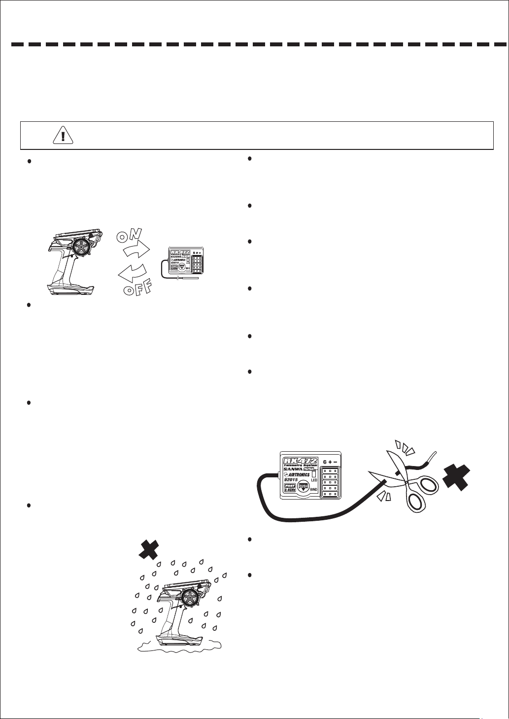
When turning the power switch of R/C System on,
please turn on in order of ① Transmitter → ② Receiver.
And when turning the power switch off,please do so in
order of ① Receiver →②Transmitter.
☆
If you reverse the order of the switches, it
causessudden high rotation of the engine and
the motor and it’s extremely dangerous.
Please use electrical noise countermeasure on the
body of your car.
☆
If metals rub against each other, it causes electrical
noise which may lead to abnormal performance.
Please be sure that all screws and nuts are not loose.
☆
Nitro or gas engine and electric motor can cause
noise also. Please use a noise countermeasure
such as a plug with resistor or noise killer
condenser.
Please make sure to run a performance check
(signalreception test) of R/C System before
operation. When it moves abnormally or it doesn’t
move, please don’t operate. Even if the test result
on a desk is normal,please be cautious when
operating for the first time especially, since the
radio wave arrival distance varies depending on
the installation method of the receiver, how the
antenna is set, the direction of the transmitter
antenna is facing and geography.
Never operate on a rainy day.
☆
The interior of the transmitter is built with
sensitive electronic parts. If water runs
on the surface of the case
and enters inside, it can
cause abnormal
performance or
malfunction and it can be
dangerous.
If the receiver or a servo
☆
sinks in the water,
immediately collect it and
dry the interior. When the
interior is dry,please
submit it to the Sanwa
Service for inspection even if it performs normally.
The receiver is a precise instrument. Please do not add a strong
impact or vibration.
☆
Use a thick sponge to prevent vibrations.
Install the receiver as far as possible from the speed controller,
motor and the battery.
When installing the receiver on a metallic chassis or a carbon
chassis, use three layers of double adhesive tape pieces to
keep the receiver from touching the chassis.
When there is a radio disturbance, change the installation
location of the receiver or change from a vertical placement to a
horizontal placement or vice versa.
Don't place a motor cord or a battery cord close to the receiver
since it can cause abnormal performance.
Keep the antenna of the receiver out as much as possible. And
keep it straight and stretched. Don't cut the extra length of the
line or bend it.
☆
It’s dangerous when the antenna is short since the range of
travelling becomes narrow.
☆
Never cut the antenna.
Don't place the antenna close to a motor cord or a battery cord.
Using a conductive piano wire on a metallic chassis or carbon
chassis can cause abnormal performance from electrical noise.
Don’t place a piano wire close to the chassis.
1
Warning Precaution For Operating RC Car
Note About Handling the Transmitter
When operating an RC car, please make sure to follow the
following notes and avoid giving trouble to others.
Maintain the body of the car (boat) in a perfect condition
and check the safety.
Do not operate an RC car in a crowd or on a public road.
Make sure to disconnect the connector of the power
battery and remove the power battery from the car after
operation.
When operating simultaneously with other RC users, make
sure to have a control staff and follow the instruction of the
control staff.
Try not to interfere with other people’s operation.
Be sure to apply for a radio control insurance. For
application to apply a radio control insurance, inquire a
radio control operator registration agency.
Be sure to install a “muffler (sound absorber)” with a
silencing effect on an engine car.
Don't start engine early in the morning.
Please make sure to clean the location used for operation
before you leave.
Note About Operation
Don't use this RC system for other than model use.
Don't hit, drop or subject to strong impact.Touching the
transmitter, receiver, servos or FET speed controller with a
hand stained with tire traction agent can cause malfunction
or deforming the case.
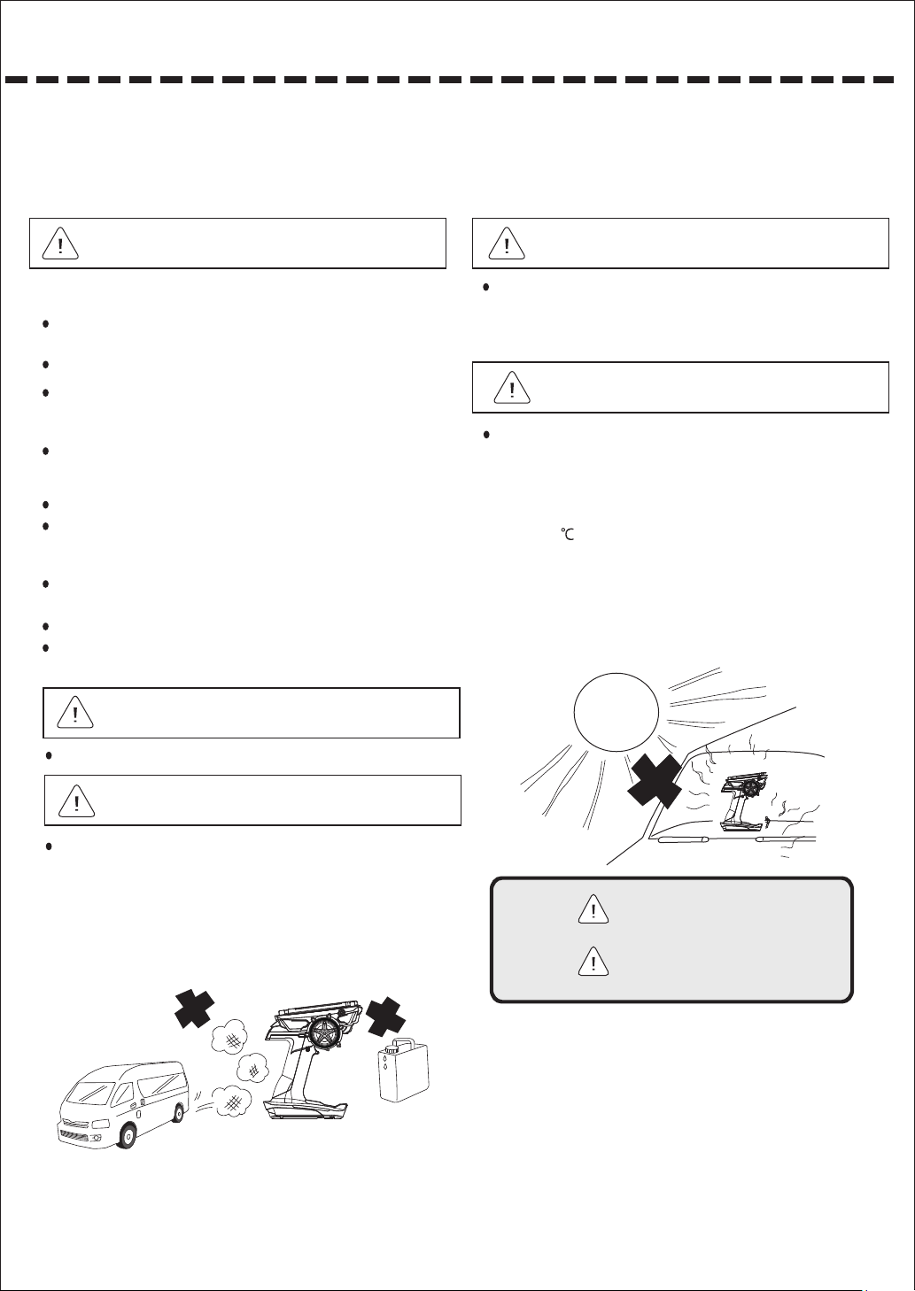
Note Storage Location
Don't store the product in the following locations:
☆
Extremely hot or cold place.
☆
Place exposed to the direct sunlight for long hours.
☆
Especially if the product is left in a closed car with a direct
sunlight hitting, the temperature inside the car can rise
above 80 depending on the season. It can cause
deforming or malfunction.
☆
Place with high humidity and poor ventilation
☆
Place with vibrations
☆
Place with dust, steam or heat
☆
Place that is blown with engine exhaust gas or a place
close to a fuel can
Note Daily Maintenance
When exhaust gas or fuel of the engine is on the product,
wipe with a soft dry cloth. When the product is heavily
stained, soak a soft clean cloth with water or neutral
detergent, squeeze tightly and wipe with it. Don't use
thinner, benzene, alcohol, motor cleaner or brake cleaner
since they can damage the surface finishing and alter the
quality.
What each
marks
indicate
Warning
Note
Precautions you must
follow to avoid accidents
or injury
Precautions you must
follow to avoid malfunctions
2

Safe Handling of R/C System and Precautions
Note Precautions to Use the Product Safely
● 2.4 GHz frequency band is not only used for radio control. This frequency band is shared with ISM
(Industry, Science and Medical) band. It can be affected by microwave ovens, wireless LAN, digital
cordless telephones, audio equipment, Bluetooth of game machines or cell phones and short-range
communication such as VICS. Also, be cautious about being affected by amateur radio and premises
radio stations for moving body identification since this frequency band is used for them as well.
When a harmful radio frequency interference is done to an existing radio station, stop the transmission
of the radio frequency immediately and take a measure to avoid the interference.
● For RC circuit, minimize the use of equipment that can affect 2.4 GHz systems and make sure to
check the safety beforehand. Also, follow the instruction of the facility manager.
● When operating the models behind a building or a steel tower, blocking the direction of radio wave
transmission can cause reduction of operation response or loss of control. Always operate within the
range you can visually check.
● Don't grab the transmitter antenna. Doing so can be dangerous since it can weaken the radio signal
output and narrow the range of operation.
● Don't attach any metal parts around the antenna of the transmitter.
● If you have the transmitter’s antenna extremely close to a servo or speed controller other than the
receiver, it can cause malfunction but it is an influence of a strong high frequency output and it is not
abnormal.
● The receiver is a precise instrument. Don’t subject it to strong impact or vibrations. Use a thick
sponge to prevent vibrations.
● Keep the antenna wire of the receiver out as much as possible. And keep it straight and stretched.
Don't cut the extra length of the antenna line or bend it.
● Don't place the antenna wire of the receiver close to a electrical noise source like a motor wire or a
battery wire.
● When installing the receiver on a metallic chassis or a carbon chassis, use layers of double adhesive tape pieces to keep the receiver from touching the chassis as much as possible.
3

INDEX
■ Layout and Specification of the Set・・・・・・・・・・・・・・・・・・・・・・・・・・・・5
● Layout of the Set (5)
● Specification of the Set (5)
■ Before start using・・・・・・・・・・・・・・・・・・・・・・・・・・・・・・・・・・・・・・・・・・・6 - 8
● Adjusting tension of the steering and throttle (6)
● Adjusting the adjustable trigger (7)
● About the power source, output format and Bind (8)
■ About connecting and installing the receiver・・・・・・・・・・・・・・・・・・・・9-10
● About the receiver, handling the antenna,built-in antenna receiver (9)
● About connection setup (10)
■ Names of each part of the transmitter・・・・・・・・・・・・・・・・・・・・・・・・・11-12
■ How to use each feature・・・・・・・・・・・・・・・・・・・・・・・・・・・・・・・・・・・・13-60
● About Key Operation (13)
● About Power On Alarm (13)
● About the Display Panel (14)
● About the Menu Structure (15)
● About Short Cut Menu (16-18)
• Direct Model Select (16)
• Quick Setup (17-18)
● Setting [SETTING] (19-32)
• Dual Rates (D/R] (19)
• Speed [SPEED](20)
• Curve [CURVE] (21-24)
• Fail Safe [F/S] (25)
• Base [BASE] (25-28)
• Reverse [REV] (26)
• Sub Trim [SUB-T] (26)
• End Point Adjustment [EPA] (27-28)
• Trim [TRIM] (29-30)
• Anti-Lock Brake [ALB] (31)
• Offset [OFFSET] (32)
• Throttle Type [TH TYPE] (32)
● AUX [AUX] (33-36)
• Step AUX [STEP AUX] (33)
• Point AUX [POINT AUX](33)
• 4 Wheel Steering [4WS] (34)
• Motor On Axle [MOA] (34)
• AUX Mixing [AUX-MIX] (35)
• Code AUX [CODE AUX] (36)
● Timer [TIMER] (37-39)
• Setup [SETUP] (37,38)
• Lap Timer [LAP TIMER] (38)
• Interval Timer [INT TIMER](39)
• Down Timer [DOWN TIMER] (39)
● Telemetry [TELEMETRY] (40-44)
• LOG [LOG DATA] (40)
• Telemetry Setting [TELEMETRY SETTING] (43)
• Graph Setting [GRAPH SETTING](44)
• Telemetry Switch [TELEMETRY SWICH](44)
● Model [MODEL] (45-48)
• Model Select [MODEL SELECT] (45)
• Model Name [MODEL NAME](46)
• Model Copy [MODEL COPY] (47)
• Model Clear [MODEL CLEAR] (48)
● System [SYSTEM] (49-60)
• Bind [BIND] (49-50)
• Key Assign Switch [KEY ASSIGN SW](51)
• Key Assign Trim [KEY ASSIGN TRIM] (52)
• Custom List [CUSTOM-LIST] (53)
• AUX TYPE [AUX TYPE] (54)
• Racing Mode [RACING MODE] (55)
• Battery [BATTERY] (56)
• Buzzer [BUZZER] (56)
• LCD [LCD] (57)
• LED [LED] (57)
• Clock [Clock] (58)
• Setup [SETUP] (58)
• Calibration [CALIBRATION] (59)
• Firmware [Firmware] (60)
■Key Assign Features Overview・・・・・・・・・・・・・・・・・・・・61
■ About handling the sensor ・・・・・・・・・・・・・・・・・・・・・・・62
■Index・・・・・・・・・・・・・・・・・・・・・・・・・・・・・・・・・・・・・・・・・・63
■At a time like this・・・・・・・・・・・・・・・・・・・・・・・・・・・・・・・・64
■Service and Support 65
■FCC Compliance Statement
・・・・・・・・・・・・・・・・・・・・・・・・・・・・
・・・・・・・・・・・・・・・・・・・・・・
66
4
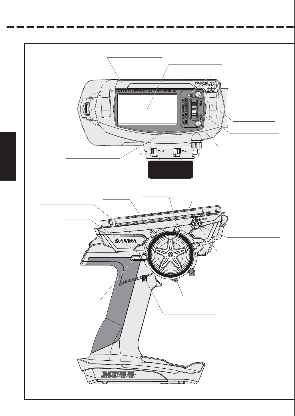
Names of each part of the transmitter
Carrying handle
(Movable)
Names of each part of the
transmitter
送
信
機
各
部
の
名
称
Function LED
Display Panel
LED
*LED will be on when
Telemetry is ON and
Receiver Battery is OFF.
LED will be flashing
while Telemetry alram
is active.
Back Button
Select Button
Multi-Selector
X illumination
Trim 4
(TRM 4)
Switch 2
(SW 2)
Trim 2
(TRM 2)
Trim 1
(TRM 1)
Steering Wheel
X illumination
Dial
Trim 3
(TRM 3)
Throttle Trigger
Push Switch 1
(SW1)
11
Power Switch
Trigger Position
Adjusting Screw
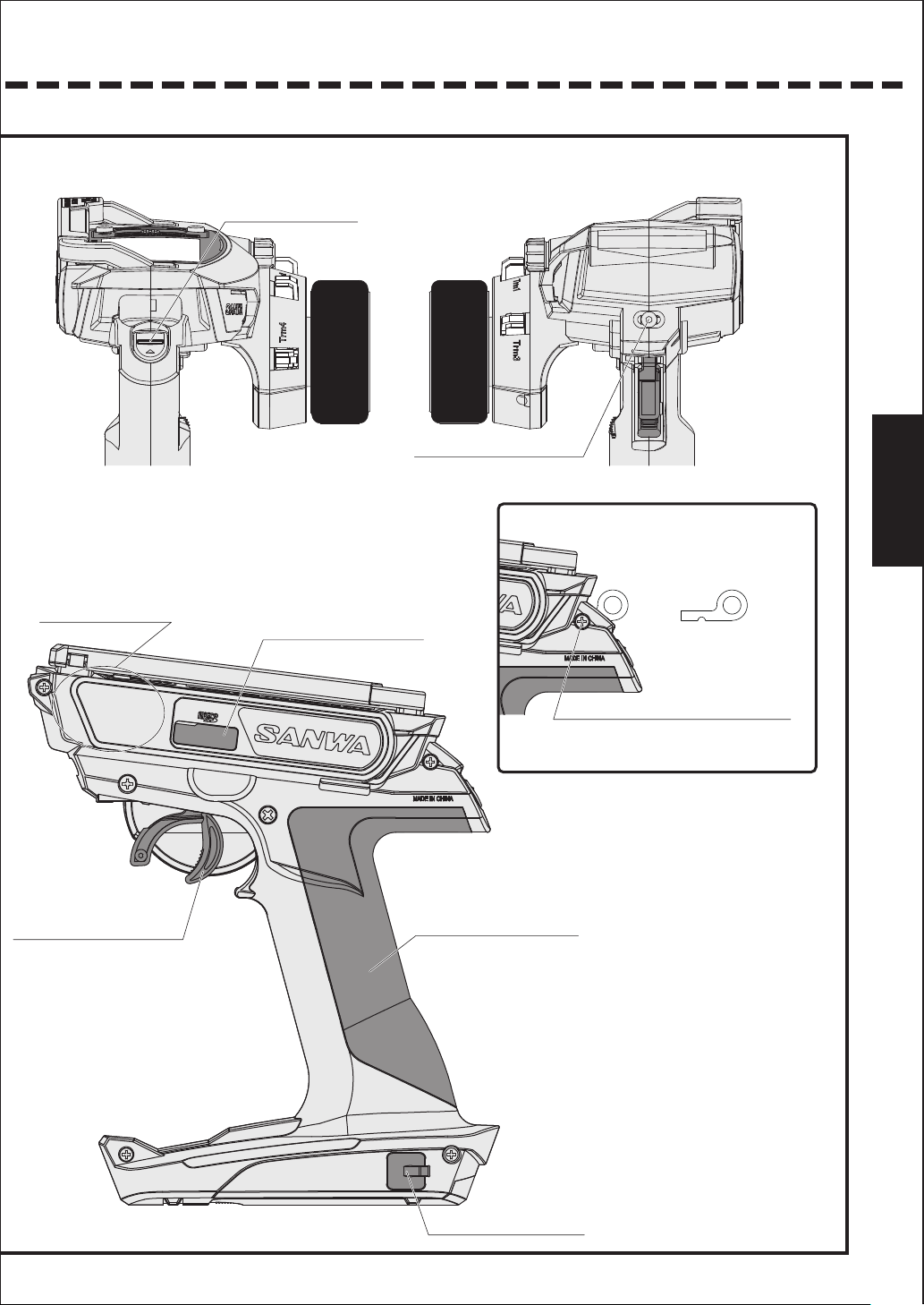
When using the Strap Hook
Names of each part of the
transmitter
送
信
機
各
部
の
名
称
Antenna interior
Throttle Trigger
Micro SD cover
Strap Hook
Remove the screw, attach the hook
and tighten the screw.
*Make sure that the hook is facing the right direction.
Grip
(Normal/Small)
Connector Cover
12
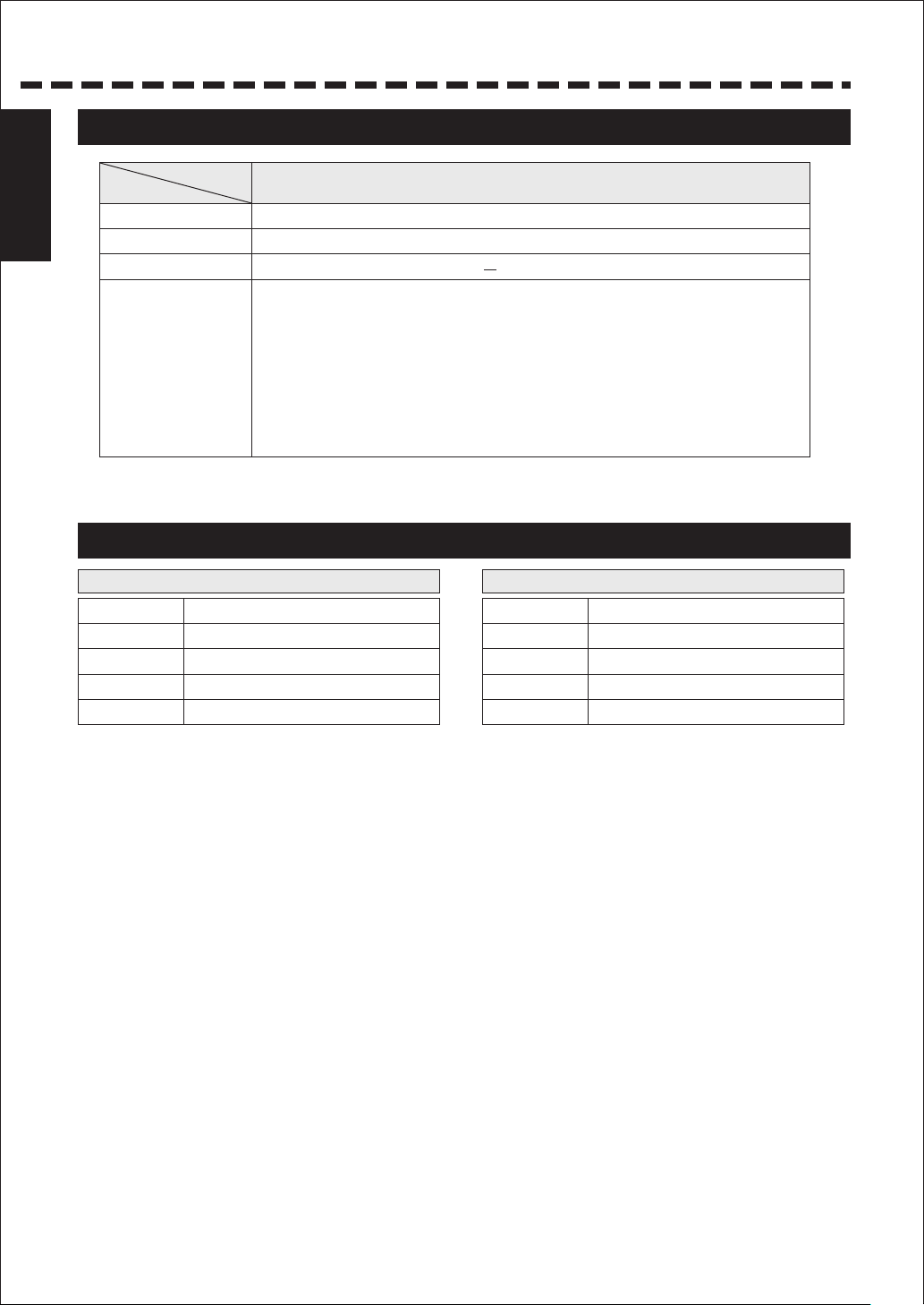
Structure and the Standard of the Set
Structure and the
Standard of the Set
Structure of the Set
RX-482 PC (Primary Component)
Transmitter
Receiver
Servos
Accessories
Set Specification
<A>Transmitter
Product No.
Output Display
Modulation Method
Power Source
Weight
*Be careful with the input voltage. If voltage above
allowable voltage is inputted, the transmitter will be
damaged.
TX-471
Analog/Digital display (Power Source Volt age Dis play )
2.4GHz Spectrum Spread System
Size AAA batteries x 3 (Corresponding voltage: DC 2.7 ~ 5.0 V)
371g
TX-471
RX-482
Strap Hook x 1
Trigger Angle Spacer x 1
Brake Trigger +1/+2 x each 1
Grip Pad S size x 1
Receiver Dust Cover x 1
Switch Harness x 1
Instruction Manual x1
●Please check what’s included before your use.
<B>Receiver
Item
Modulation Method
Size
Power Source
Weight
RX-482
2.4GHz Spectrum Spread System
18.2x24.4x27.1mm
DC3.7~7.4V
7.1g
5
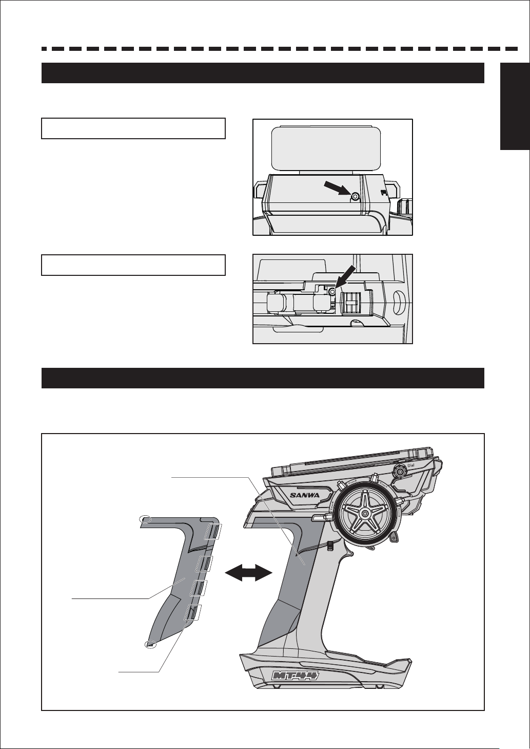
Before using
Adjusting the steering and throttle tension
With MT-44, the user can easily adjust the tension of the steering/throttle trigger to match operation of
the steering/throttle to the user’s preference.
Adjusting the steering tension
By inserting a hexagon wrench driver
(1.5mm) to the place where the arrow is
pointing at in the illustration on the right and
turning, you can adjust the tension of the
steering spring.
*The spring tension is the softest at the time
when the product is shipped out from the
factory. As you tighten with a hexagon
wrench driver (1.5mm), the spring tension
will be hardened.
Adjusting TH trigger tension
By inserting a hexagon wrench driver
(1.5mm) to the place where the arrow is
pointing at in the illustration on the right and
turning, you can adjust the tension of the
throttle spring.
Structure and the
Standard of the Set
Adjusting the grip pad
The user can choose a grip pad from two types of normal/small to suit the size of the user’s hand.
(The normal size is installed at the factory.)
Do not pull forcefully because it’s locked to the grip of the receiver with tabs of the grip pad (at 11 locations).
Grip Pad
(Normal)
Grip Pad
(Small)
Tabs
(11 locations)
6
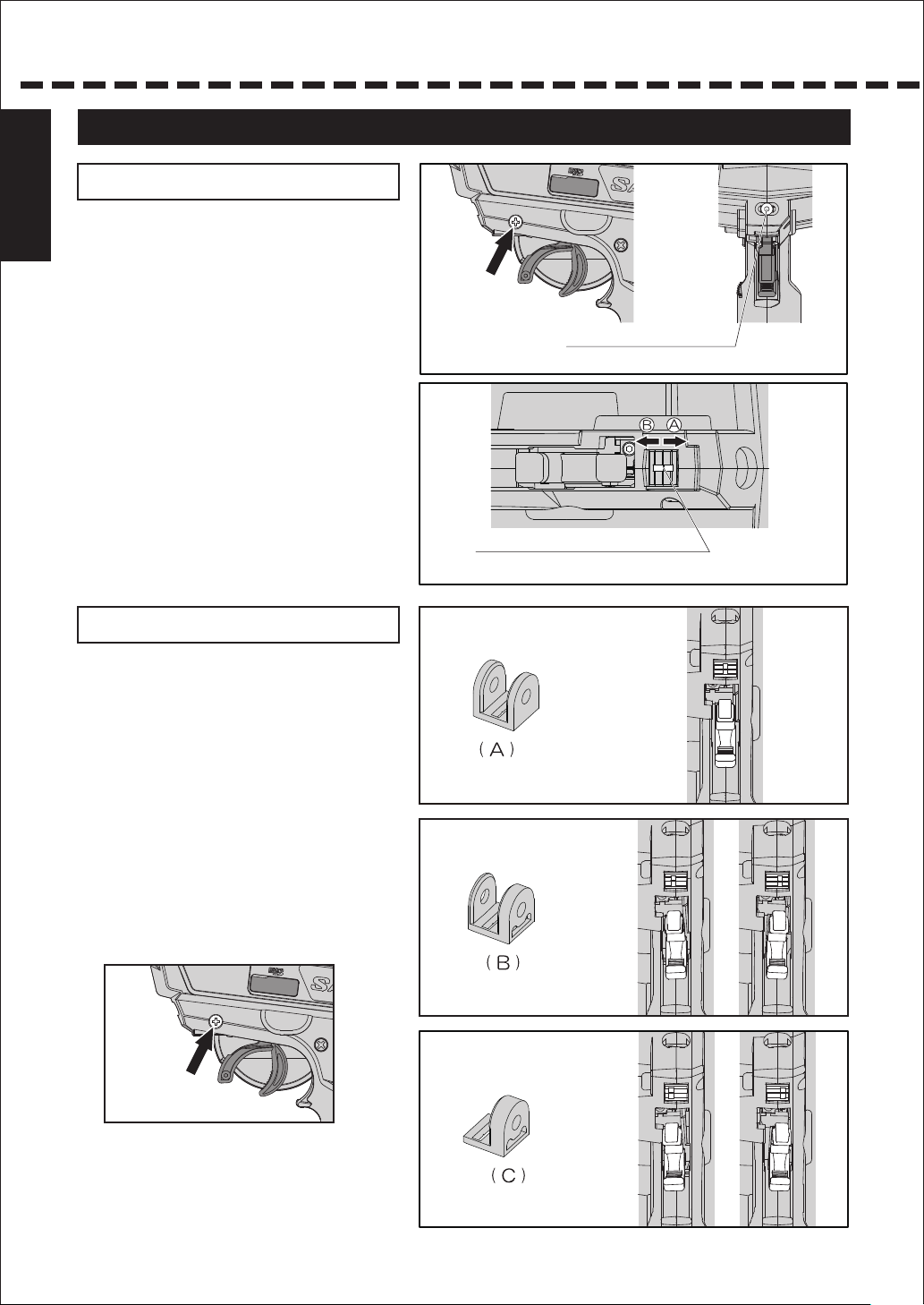
Before using
Before using
Adjusting the full adjustable trigger
Adjusting the trigger position
Loosen the fixing screws of the trigger on the back of the
transmitter. Then, adjust the adjusting screw of the trigger
position on the back of the transmitter to set the trigger at the
position of your preference. When you turn the adjusting
screw of the trigger position clockwise, the trigger position
Fixing screw of the trigger
gauge moves to the direction A. By turning it counter
clockwise, the trigger position gauge moves to the direction B.
*The range of the trigger movement is 5mm. If you turn the
screw forcefully beyond the range, it can cause malfunction.
Once you set the trigger position, tighten the fixing screw and
adjusting the trigger is done.
*Be careful with the direction of turning the screw because
the trigger position is set at the furthest point of the A side at
the factory.
Adjusting the trigger angle
By switching the angle spacer A/B/C, it is possible to adjust
the angle of the throttle trigger to five steps.
Adjusting screw
for the trigger position
Trigger position gauge
Adjustable range: approximately 5mm
Angle spacer
1) Remove the fixing screw of the trigger on the back of the
transmitter.
2) Adjust the angle by changing the direction of the angle
spacer to have an angle easy to operate.
3) Once the trigger angle is set, fix the fixing screw of the
trigger on the back of the transmitter.
Fixing screw of the trigger
Installed at the factory
Angle spacer
Angle spacer
7
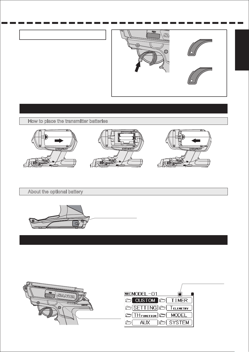
Adjustment of Brake Trigger
You can adjust trigger position according to your fingers by
replacing brake trigger included. Standard Size, +1 Size,
and +2 Sice is included.
1) Remove the brake trigger fixing screw.
2) Select Brake Trigger according to your fingers.
3) Fix the brake trigger by the screw.
BRAKE TRIGGER
FIXING SCREW
BRAKE TRIGGER
( +1 )
( +2 )
Before using
3) Fix the bakre trigger by the screw.
About the power source
How to place the transmitter batteries
Open the battery compartment cover by sliding the
①
cover to the direction of the arrow while pressing it
lightly.
Place 3 size AAA batteries. Make sure to
observe correct polarities.
③②
Align the convex part of the battery compartment cover and the
groove of the battery compartment, slide the cover to the
direction of the arrow and close tightly.
About the optional battery
●When using an optional battery, you can access to the charging port on the side of the battery from the connector cover.
Connector Cover
About Micro SD Card
MT-44 is compatible to Micro SD Cards. By using a Micro SD Card, it is possible to save model data and telemetry data.
●
Also, it is possible to do firmware update using a Micro SD Card when a firmware update of MT-44 is released.
After inseting micro SD card into MT-44, the file mnamed “MT-44” is made and the folder named “MODEL” is made.
●
The model data is saved in the folder.
If the log data is exported, the folder named “Log” is made and the data named “csv” is saved in the folder.
When micro SD card is inserted,
this mark will be on.
Micro SD Cover
8
About connection and installation of the receiver
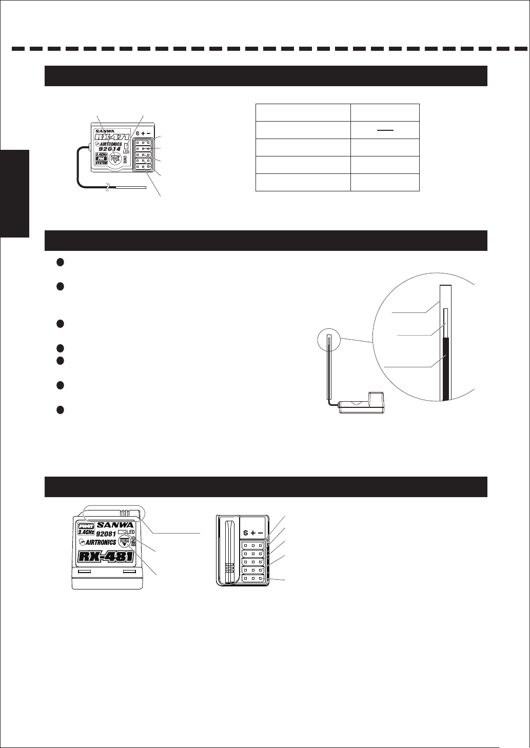
About the receiver
●RX-471(Example)
BIND Button
About connection and
installation of the receiver
LED
BATT
CH4:4ch
CH3:3ch
CH2: Throttle
(FET Speed Controller)
CH1: Steering
Condition of the Receiver LED
When receiving a signal
When it cannot receive a signal
while setting up BIND
Battery Fail Safe Operation is launched
After Battery Fail Safe Operation is launched,
it becomes unable to receive a signal.
Blue light is on
Blue light flashes.
Blue light flashes rapidly.
Blue and Red lights are on.
Red light is on.
About handling the Antenna
Reception distance may vary depending on the location where the receiver and
the antenna are installed.
To protect the reception part (3 cm from the top) of the antenna, make sure to
place the antenna in the antenna pipe as shown in the right illustration so that
the top of the antenna is not exposed outside of the antenna pipe.
Don’t bend the antenna reception part or the antenna coaxial cable because
breaking can occur inside.
Don’t pull the coaxial cable forcefully. It may damage the receiver interior.
Install the antenna on an RC car so that the antenna reception part is in as high
place as possible.
Don’t cut or bind the antenna reception part or the antenna coaxial cable since
the receiver sensitivity might decrease.
Keep the receiver antenna away from the motor and the FET Speed Controller
(including cables) and raise it straight.
Antenna Pipe
Antenna Reception part
Antenna coaxial cable
About built-in antenna receiver
BATT
Antenna Reception part
LED
BIND Button
●
Reception distance may vary depending on the location where the Antenn Reception part is installed.
●
Install the antenna so that the antenna reception part in the above illustration is as high as possible.
9
CH4:4ch
CH3:3ch
CH2:Throttle
(FET Speed Controller)
CH1: Steering
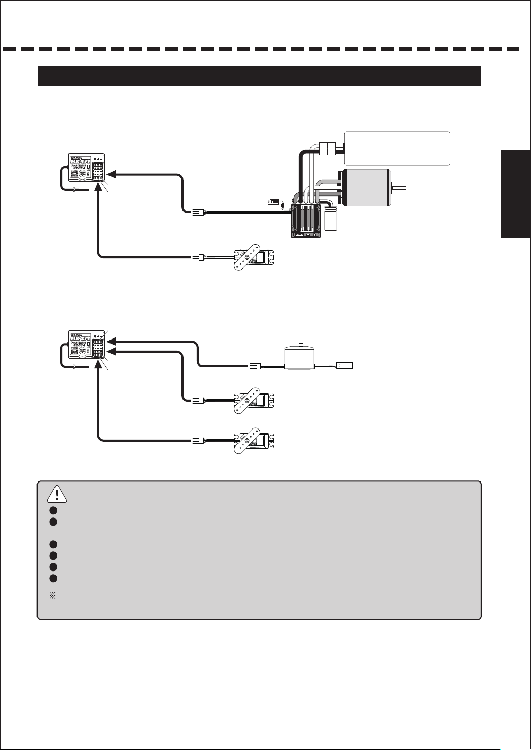
About connection setup
● Connect the receiver and servos as shown in the illustration below.
・Connection example when used on an EP car
Connecting to CH2
CH2
CH1
Connecting to CH1
Servos
• Connection example when used on a GP (engine) car
BATT
Connection to BATT
Connecting to CH2
CH2
CH1
(Steering)
(Throttle)
Power battery
Motor
FET Speed Controller
Connection to the receiver battery
About connection and
installation of the receiver
Servos
Connecting to CH1
(Steering)
Note
If the connector is disconnected due to a vibration during operation, it can cause runaway. Connect the connector of the receiver, servos and switches securely.
Because the receiver is susceptible to vibration, impact and water, make sure to take measures for vibration-proof and waterproof. Negligence of taking these
measures can cause runaway.
When installing the receiver, keep the receiver away from a carbon chassis and metallic chassis.
If metal parts installed on an RC car touch each other, it can cause noise that affects reception performance and it can cause runaway.
Make sure to install a noise killer condenser on the brush motor for electric RC cars. Without a noise killer condenser, it can cause noise and runaway.
For R/C System parts such as the transmitter, receiver, servos, FET Speed Controller and transmitter battery, use genuine SANWA products.
When combining products other than genuine SANWA products, modifying, adjusting or exchanging parts is done at a place other than SANWA, we do not take
any responsibility.
10
Usage of each feature
Push
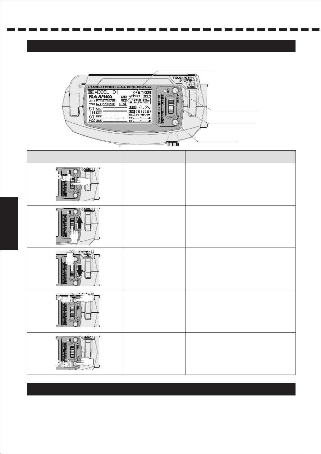
About Key operation
●
The user can set up and make a calling easily with the Multi-Selector and Select button/Back button.
Key operation PerformanceNames
Display Panel
Select Button
Multi-Selector
Back Button
Enter
Push
Usage of each feature
Multi-Selector Up ● The cursor moves upward.
Multi-Selector Down
Push
Select ● Selects a channel or feature.
Back/Cancel ● Goes back to one step before.
● Moves to the setup screen from the top screen.
● Selects a feature and item to set.
● By long pressing the button, the setting goes back
to default.
● The set value increases.
● Moves the cursor downward.
● The set value decreases.
● Cancels the setting.
13
About Power On Alarm
● MT-44 displays “No Operation” with a warning alarm after 10 minutes of no operation of the steering
wheeel, throttle trigger and switches. Alarm is turned off, if the steering wheel, throttle trigger or a switch
is operated. In case you do not use them, turn the power switch off.

About the Display Panel
● Each feature of MT-44 allows you to directly select a feature with the Multi-Selector.
● You can set up each channel feature separately.
● As you turn the power switch on, the top screen launches after the boost screen
is displayed(when the boot setting is on).
When changing each setting, select the menu by operating the Multi-Selector.
Name
Model Number
Top Screen
Effect Indicator
Telemetry Screen
Each Telemetry
data
Micro SD card
Log
Timer
As you move up/down with the Multi-Selector,
it becomes a toggle between Top Screen/Telemetry Screen.
Telemetry
Racing Mode
Battery Indicator
Clock
If effect or function is active,
icon will be displayed.
Timer
Log Timer
Trim
By connecting each sensor to RX461
or RX462, using combination of
RX461/RX462 and SUPER VORTEX
or SV-PLUS series, and turning the
Telemetry feature on, data is sent to
the transmitter and it is displayed
on the Telemetry Screen.
Usage of each feature
Menu Window
•Select the Menu
(Screen example)
*Enter operation from
the Top Screen
14
Usage of each feature
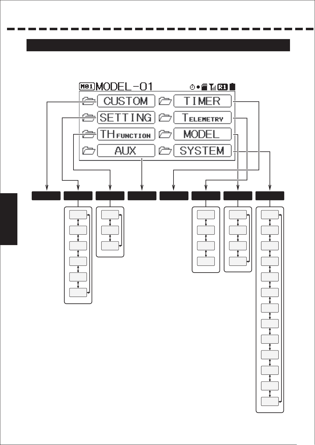
About the Menu structure
● The user can set up features and do model memory call easily by using each key.
● The Menu consists of Setting, AUX, Model, Timer, Telemetry and System Menu, and related features
are included in each menu.
Usage of each feature
CUSTOM
(P.53)
Custom Menu
It is set with the
Custom List within
the System.
SETTING
D/R
(P.19)
SPEED
(P.20)
CURVE
(P.21~24)
TH-FUNCTION
ALB
(P.31)
OFFSET
(P.32)
TH TYPE
(P.32)
F/S
(P.25)
BASE
(P.25~28)
TRIM
(P.29、30)
AUX
(P.33~36)
Set up all items
of the accessory
channels of
3ch/4ch.
TIMER
(P.37~39)
Various timer
setups and lap
display menu.
TELEMETRY
LOG DATA
(P.40)
TELEMETRY SETTING
(P.43)
GRAPH SETTING
(P.44)
TELEMETRY SWITCH
(P.44)
MODEL
SELECT
(P.45)
NAME
(P.46)
COPY
(P.47)
CLEAR
(P.48)
SYSTEM
BIND
(P.49、50)
KEY ASSIGN
(P.51、52)
CUSTOM-LIST
(P.53)
AUX TYPE
(P.54)
R-MODE
(P.55)
BATTERY
(P.56)
BUZZER
(P.56)
LCD
(P.57)
LED
(P.57)
CLOCK
(P.58)
SETUP
(P.58)
CALIBRATION
(P.59)
FIRMWARE
(P.60)
15
About Short Cut Menu
MT-44 has a feature of Short Cut Menu that is launched as the user performs key operation
when operating the power switch.
If you turn the power switch on while pressing the Back Button, it becomes the Direct Model
Select and if you turn the power switch on while doing Enter operation, the Quick Setup
feature launches.
Direct Model Select is a feature for quickly selecting a model to run and Quick Setup is a
feature for various setup with easy operation when setting up a new RC car.
Quick Setup feature is set in the following order using the Enter operation after launching.
Selecting Model → Selecting Type → Initializing Model → Selecting RF Modes → Selecting
Response Mode → BIND → Setting Base
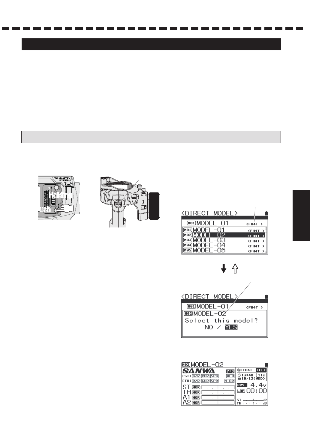
Direct Model Select < DIRECT MODE >
Direct Model Select
1) Turn the power switch on while pressing the Back button.
Power Switch
ON
HoldingHolding
Push
2) Selecting Model
Select a Model you wish to call with Multi-Selector.
Selection range: M01 ~ M20
3) Move the cursor to the Model you wish to call and
do Enter operation. A message is displayed on the
screen. Select a Model following the display.
⇒
①
MODEL Selection Screen
RF MODE display
ENTER BACK
Model to be changed
②
Confirmation Screen
NO →
Back to
YES→ Change Model and move to the top.
①
to is displayed.
Usage of each feature
16
Usage of each feature
About Short Cut Menu
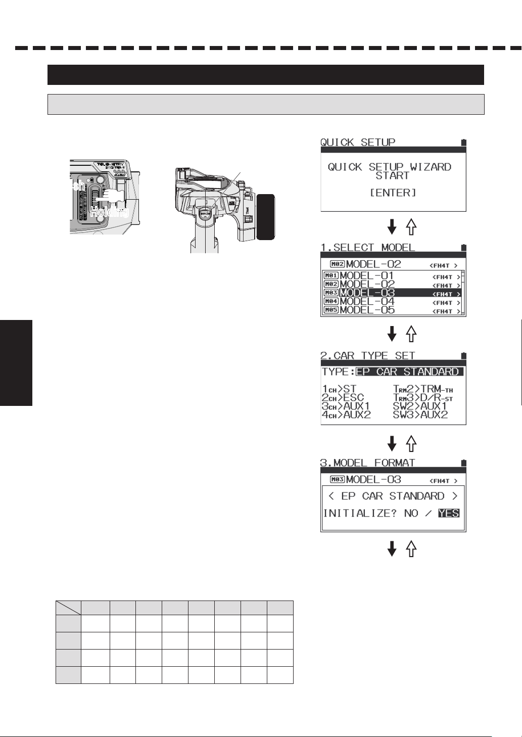
Quick Setup <QUICK SETUP WIZARD>
● Quick Setup
1) Turn the power switch on while doing Enter operation
Power Switch
ON
Push
⇒
Holding
2) Quick Setup screen is displayed.
As you do Enter operation, Quick Setup Wizard is
launched.
ENTER BACK
Usage of each feature
3) When the screen is changed to Model selection screen,
ENTER BACK
select a Model to set up by using Multi-Selector.
When a Model to set is selected, set with Enter operation.
4) When the screen is changed to Car Type selection
screen, select a Car Type using Multi-Selector.
When a Car Type is selected, set with Enter operation.
Setting up Type
○ Setting range: EP CAR STANDARD
ENTER BACK
EP CAR (LED UNIT)
EP CAR (SVZ)
EP CAR (SVD)
GP CAR STANDARD
1/5 GP CAR DUAL BR1
1/5 GP CAR DUAL BR2
CRAWLER 4WS/MOA
○ Default: EP CAR STANDARD
ENTER BACK
*Channel operation of each type will be as follows.
Channel operation specifications for each Type
CH
CH1
CH2
CH3
CH4
TYPE
EP CAR
EP CAR
STANDARD
STEERING
ESC
AUX1
AUX2
EP CAR
(LED UNIT)
(SVZ)
STEERING STEERING STEERING STEEIRING
ESC ESC ESC
LED-ST
CODE1
CODE2
EP CAR
(SVD)
CODE1
CODE2
GP CAR
STANDARD
THROTTLE
/BRAKE
AUX1
AUX2
1/5 GP
DUAL BR1
STEERING
1
THROTTLE
/BRAKE R
STEERING
2
BRAKE FLED-TH
1/5 GP
DUAL BR2
STEERING
THROTTLE
BRAKE
R
BRAKE
F
CRAWLER
4WS/MOA
STEERING
F
ESC
F
STEERING
R
ESC
R
17
*Select a type to be used according to an RC.
5) When deciding the car type using Enter,
the screen changes to Initialization (Model Initialization) screen.
Do initialization following the message.
ENTER BACK
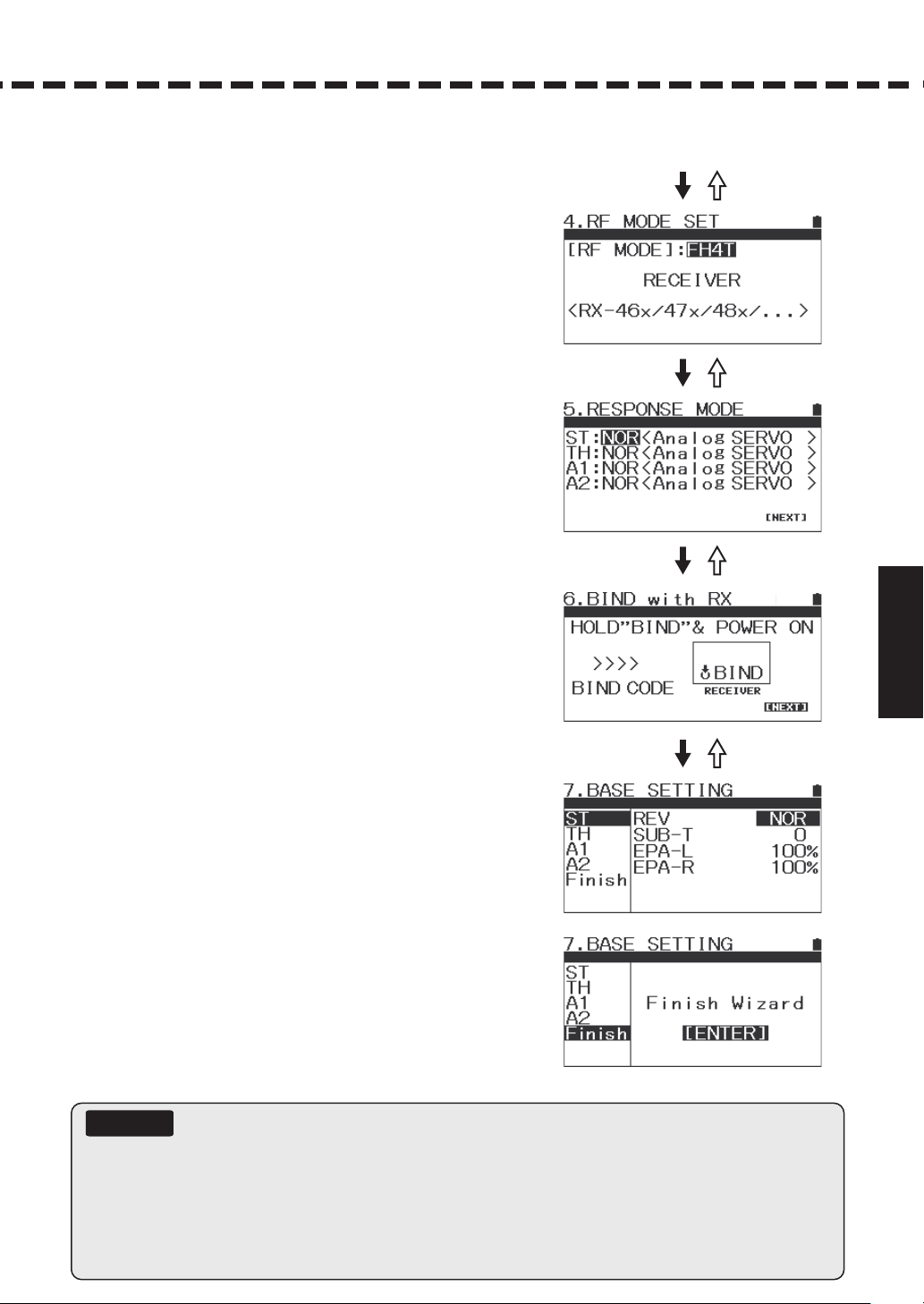
6) When initializing (Initializing Model) is completed, the scr
changes to RF Mode Selection Screen. Set RF Mode by using
Up key/Down key and finalize with th水Enter key for the
receiver to be used.
○ Setting range: FH4T/FH3
○ Default: FH4T
・Compatible Receivers:
FH4T: RX-482, RX-481, RX-472, RX-471,
7) Once RF Mode for the receiver is determined, the screen
changes to the Response Mode screen.
Set Response Mode according to the servos and the equipmen
to be used.
Set with Up key/Down key and finalize with the Enter key.
○ Setting range: NOR (Normal/Analog Servos)
SHR (High Response/Digital Servos)
SSR (Super Response/SRG Servos)
○ Default: NOR (Normal/Analog Servos)
RX-47T, RX-462, RX-461,
SV-Plus Series
FH3: RX-451R, RX-451, RX-381, RX-380
een
ENTER BACK
ENTER BACK
t
Usage of each feature
ENTER BACK
8) When Response Mode setting is completed,
the screen changes to BIND Set up Screen.
Follow the screen message and start Binding.
9) When Binding (BIND) is done, the screen changes to
the Base Set Up screen. Complete setting for each channel
(refer to P. 25-28).
10) When Base setting is done, Set Up Wizard will end.
If you press the Enter button, the screen changes to the
Top screen.
Important
● Please note that the analog servos do not work in SHR/SSR modes. If you mistakenly use the analog servos in SHR/SSR mdoes,
it does not work normally and the servos will be broken. Never use analog servos in SHR/SSR modes.
For digital servos (SRG, ERB, ERS Series and Digital ERG Series), either NOR or SHR mode works.
● SSR mode works only for SRG Servos, SUPER VORTEX/SV-PLUS series, HV-12, STOCK SPECIAL and HV-01.
● MT-44 will not be SSR mode by using RX-451R to BIND with SHR display. It works as the display shows.
● With SHR/SSR mode, BL-RACER, BL-FORCE, F2000, F2200. F3000 F3300, SBL-01 02 and 03CL do not work.
Make sure to use them in NOR mode.
● SV-08, HV-10, HV-12 and F2500 work in NOR/SHR modes.
18
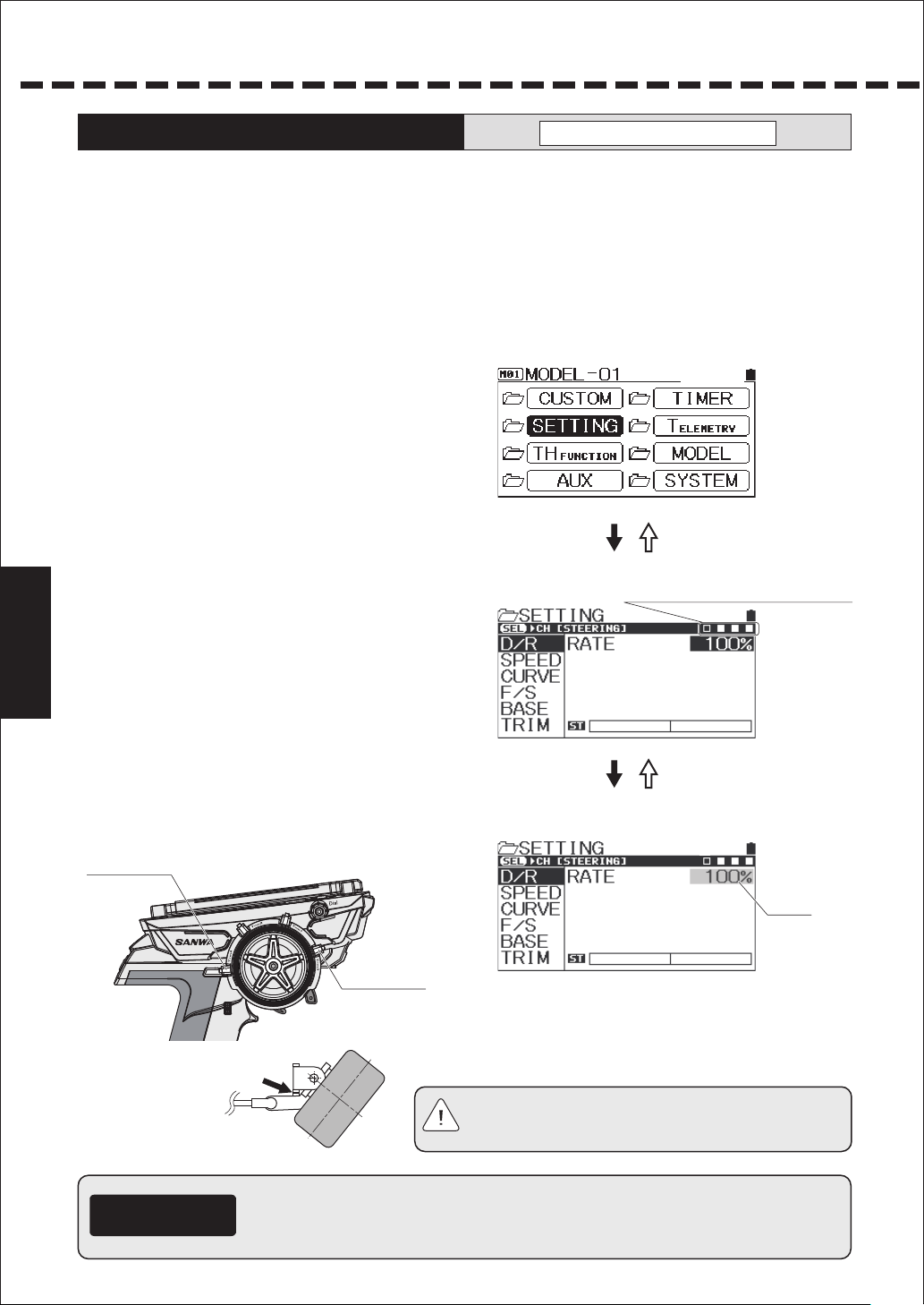
Usage of each feature
Dual Rates [D/R]
● You can adjust rudder angle when operating the steering wheel and throttle trigger to their peak.
To correspond to the RC car or road condition, adjust the rudder angle as you operate.
*You can adjust steering for both right and left at the same time and throttle separately for high
and brake sides. You can also adjust the brake side more precisely than adjusting with EPA.
● Donʼt increase the setting rate of dual rates (D/R) from the condition in which the linkage locks
by operating the steering wheel and throttle trigger.
● You can also adjust more precisely by adjusting dual rates of the throttle side.
*When AUX1/AUX2 are set to CODE5/CODE10, setting change of D/R will not be reflected
to the performance.
1) Select features [ST/TH (H, L)/AUX1/AUX2)
to adjust with the Select key.
2) Determine the feature to adjust with the Enter key
and adjust the setting rate with the multi-select key.
3) Adjust the valus of DUAL RATE by multi-selector.
Usage of each feature
4) During operation, the steering dual rates can be
adjusted with Trim 3, brake dual rates can be
adjusted with Trim 4. Itʼs possible to assign other
features to Trim 3 and Trim 4 with the key assign trim
feature (P. 52).
SETTING
ENTER BACK
DUAL RATE SETTING SCREEN
Select Channel by Multi-selector button.
*When cancelling a selected feature,
operate the Back button.
○ Setting range: ST/TH-H/AUX1/AUX2:0%~100%
TH-L:0%~120%
○ Default: ST/TH/AUX1/AUX2:100%
Trim 4
Trim 3
*Make sure that the servos do
not lock to make clicking
sound! Note)
The same for throttle.
Supplement
● Adjust the end point of the steering/throttle linkage before
adjusting dual rates (P. 27, 28).
ENTER BACK
Steering Dual Rates Selection Screen
Note
● If the linkage is locked for a long period,
it can cause the servo motor breakage.
Flashing
19
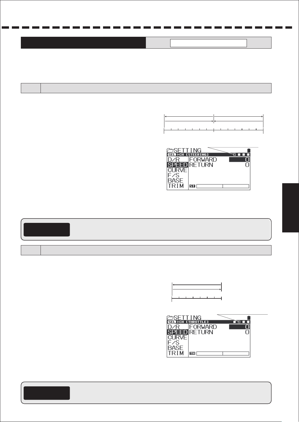
SPEED
●
Features to control the speed of the servos used for steering and throttle. By setting, the RC car is not affected even
SETTING
when doing a sudden operation. On the steering side, smooth corner work becomes possible and on the throttle side,
stable rising from a corner by throttle work with saved power.
* When setting AUX TYPE to [CODE5/CODE10], adjusting the speed feature of the AUX channel does not affect the performance.
* When setting the speed of the AUX channel, do so using steering/throttle as a reference.
[ST] Steering Speed
●A feature to delay the speed of the steering servos against the steering operation. You can set speed for steering
forward and returning individually. For steering operation slower than setting, the speed feature does not work.
1) Select [ST (Steering)] with Up key/Down key.
2) Setting on the forward side [FORWARD]
Select [FORWARD] with the Enter key and adjust the
setting value with Up key/Down key.
*When cancelling a selected feature, use the Back key.
L
End
FORWARD
RETURN
N
Neutral
Choose [ST] by selector button.
○ Setting range: 0~-100
○ Default: 0
3) Setting on the Return side (RETURN]
Select [RETURN] with the Enter key and adjust the setting value with Up key/Down key.
○ Setting range: 0~-100
○ Default: 0
*Adjust during actual operation. When not using the features or when a setting value cannot be determined even after
adjustment, set the value to 0% (linear).
FORWARD
RETURN
R
End
Usage of each feature
●For driving an RC car, steering operation that suits the movement of the RC car is important and excessive operation
Supplement
is not recommended. Steering speed can minimize unnecessary operation and enables smooth cornering.
●When steering speed and steering curve are combined, the effect is doubled.
[TH] Throttle Speed
●
A feature to slow down the performance speed of the throttle se rvos and delay the response of the speed controller against thr ottle
operation. You can set speed for entering throttle (Forward) and returning (Return) individually. The speed feature does not work with
throttle operation slower than the setting. *Setting is only for High side and Brake side cannot be set.
1) Select [TH (Throttle)] with Up key/Down key.
2) Setting on the forward side [FORWARD]
Select [FORWARD] with the Enter key and adjust the
setting value with Up key/Down key.
*When cancelling a selected feature, use the Back key.
H
End
○ Setting range: 0~-100
○ Default: 0
3) Setting on the Return side (RETURN)
Select [RETURN] with the Enter key and adjust the setting
value with Up key/Down key.
○ Setting range: 0~-100
○ Default: 0
*Adjust during actual operation. When not using the features or when a setting value cannot be determined
even after adjustment, set the value to 0% (linear).
● For driving an RC car, throttle operation that suits the movement of the RC car is important and excessive operation
Supplement
is not recommended. Throttle speed can minimize unnecessary operation and enables smooth performance.
● When throttle speed and throttle curve are combined, the effect is doubled.
FORWARD
RETURN
N
Neutral
Choose [TH] by selector button.
20

Usage of each feature
Curve [CURVE]
●Features to change the operating quantity of the servos again st operation of the steering
wheel/throttle trigger. When the setting value is on the plus (+) side, it responds quickly,
when on the minus side (-), it responds mildly.
● You can select a curving movement exponential (EXP) and a linear movement adjustable rate control (ARC).
* When setting AUX TYPE to [CODE], adjusting the curve feature of the AUX channel does not affect
the performance. When setting curve for the AUX channel, do so using steering/
・Exponential (EXP)
Quick
Servo Operating Quantity
Normal
Mild
Steering Wheel L End Operating Quantity
Throttle Trigger H End Operating Quantity
Usage of each feature
・Adjustable Rate Control (ARC)
You can change the position where operation is changeable by adjusting the setting of POINT.
Quick
Normal
Neutral Position
Servo Operating Quantity
Servo Operating Quantity
Steering Wheel R End Operating Quantity
Throttle Trigger B End Operating Quantity
Servo Operating Quantity
Setting/SETTING
Quick
Normal
Quick
throttle as a reference.
Mild
POINT
Normal
Mild
Steering Wheel L End Operating Quantity
Throttle Trigger H End Operating Quantity
Neutral Position
Steering Wheel R End Operating Quantity
Throttle Trigger B End Operating Quantity
Mild
[ST] Steering Exponential
●
You can change the steering feature from Mild to Linear to Quick. In general, if you find your RC car oversteering,
change the setting to the minus side and if you find under steering, change to the plus side.
Steering Exponential is a simultaneous setting for L and R.
1) Select ST with the Select button and
set CURVE TYPE of ST to [EXP] with the multi-selector.
2) Adjust the setting value with the multi-selector.
○Setting range: -100%~100%
○Default: 0%
*When cancelling a selected feature, use the Back button.
Stee ring
Operatio n Position
21

[TH] Throttle Exponential
●
You can change the throttle feature from Mild to Linear and to Quick. In general, when operating
on a slippery road or if you find over powering, change the
operating on a high-grip road or if you find lack of power i
You can set the High side and the brake side separately.
*Selection of the High side and the brake side is done
by trigger operation.
1) Select TH with the Select button and set
CURVE TYPE of TH to [EXP] with the multi-selector.
2) Adjust the setting value with the multi-selector.
setting to the minus side and when
n the power unit, change to the plus side.
Select H/B by trigger operation.
○Setting range: -100%~100%
○Default: 0%
[AUX1]
●You can change the operation feature of AUX1 from Mild to Linear to Quick.
You can set the High end and the Low end separately.
*When setting AUX1 to [CODE5/CODE10] in AUX TYPE,
changing the setting does not affect the performance.
1) Select AUX1 with the Select button and
set CURVE TYPE of AUX1 to [EXP] with the
multi-selector.
2) Adjust the setting value with the multi-selector.
○Setting range: -100%~100%
○Default: 0%
[AUX2]
●You can change the operation feature of AUX2 from Mild to Linear and to Quick.
You can set the High end and the Low end separately.
*When setting AUX2 to [CODE5/CODE10] in AUX TYPE,
changing the setting does not affect the performance.
AUX1 • Exponential
AUX2 • Exponential
Throttle Operation Position
Usage of each feature
1) Select AUX2 with the Select button and set
CURVE TYPE of AUX2 to [EXP] with the multi-selector.
2) Adjust the setting value with the multi-selector.
○Setting range: -100%~100%
○Default: 0%
22

Usage of each feature
CURVE
SETTING
[ST] Steering Adjustable Rate Control
●
You can change the steering feature from Mild to Linear and to Quick. In general, if you find your RC car
oversteering, change the setting to the minus side and if you find understeering, change to the plus side.
Steering Adjustable Rate Control is a simultaneous setting for L and R.
1) Select ST with the Select button and set CURVE TYPE of ST to
2) Setting Rate [RATE]
Select [RATE] with the multi-selector and
adjust the setting value.
○Setting range: -100%~100%
○Default: 0%
3) Setting Point [POINT]
Select [POINT] with the multi-selector and
adjust the setting value.
Usage of each feature
○Setting range: 5%~95%
○Default: 0%
* When cancelling a selected feature, use the Back button.
Steering Operation Position
[ARC] with the multi-selector.
[TH] Throttle Adjustable Rate Control
●
You can change the throttle feature from Mild to Linear and to Quick. In general, when operating
on a slippery road or if you find over powering, change the setting to the minus side and when
operating on a high-grip road or if you find lack of power in the power unit, change to the plus side.
You can set the High side and the brake side separately.
*Selection of the High side and the brake side is done by trigger operation.
1) Select TH with the Select button and set
CURVE TYPE of TH to [ARC] with the multi-selector.
2) Setting Rate [RATE]
Select [RATE] with the multi-selector and adjust
the setting value.
○Setting range: -100%~100%
○Default: 0%
3) Setting Point [POINT]
Select [POINT] with the multi-selector and adjust the setting value.
○Setting range: 5%~95%
○Default 50%
Select H/B by trigger operation.
Point Setting Position
23
* When cancelling a selected feature, use the Back button.

[AUX1]
●You can change the AUX1 performance feature from Mild to Linear and to Quick.
You can set the High side and the Low side separately.
*When setting AUX1 to [CODE5/CODE10] in AUX TYPE,
changing the setting does not affect the performance.
1) Select AUX1 with the Select button and set
CURVE TYPE of AUX1 to [ARC] with the multi-selector.
2) Setting Rate [RATE]
Select [RATE] with the multi-selector and
adjust the setting value.
AUX1 Adjustable Rate Control
○Setting range: -100%~100%
○Default: 0%
3) Setting Point [POINT]
Select [POINT] with the multi-selector and adjust the setting value.
○Setting range: 5%~95%
○Default: 0%
*When cancelling a selected feature, use the Back button.
[AUX2]
●You can change the operation feature of AUX2 from Mild to Linear and to Quick.
You can set the High side and the Low side separately.
*When setting AUX2 to [CODE5/CODE10] in AUX TYPE,
changing the setting does not affect the performance.
1) Select AUX2 with the Select button and set
CURVE TYPE of AUX2 to [ARC] with the multi-selector.
2) Setting Rate [RATE]
Select [RATE] with the multi-selector and
adjust the setting value.
AUX2 Adjustable Rate Control
Point Setting Position
Usage of each feature
○Setting range: -100%~100%
○Default: 0%
3) Setting Point [POINT]
Select [POINT] with the multi-selector and adjust the setting value.
○Setting range: 5%~95%
○Default: 0%
*When cancelling a selected feature, use the Back button.
Point Setting Position
24

Usage of each feature
Fail Safe [F/S]
●Fail Safe Operation is a feature to keep the servos in a predetermined position for each channel in the event
that the receiver cannot receive a signal from the transmit ter. A feature to keep the servos in a predetermined
position for the servo of the throttle channel (2ch) in the event that the battery voltage on the receiver side of
an engine RC car goes below the set voltage is Battery Fail Safe Operation.
●Battery Fail Safe Operation cannot be set when the throttle channel (2ch) is set to FREE/HOLD (*Battery Fail
Safe Operation works only for the throttle channel).
*Donʼt use Battery Fail Safe Operation feature for electric RC cars.
1)Select F/S with the multi-selector and select a channel to s et
fail safe operation (ST/TH/AUX1/AUX2) with the select butt on.
2)Enter the set channel and operate the multi-selector.
The fail safe mode setting changes in order of FREE -> FS
->HOLD.
○Setting range: FREE/FS(100%~-100%)/HOLD
○Default: FREE
*About each mode
FREE (Free Mode): When thre receiver cannot receive the signal from the transmitter,
the signal output to the servo stops and the servo will be free.
FS (Fail Safe Mode):When the receiver cannot receive the signal from the transmitter,
the servo will be held in the set position.
Usage of each feature
HOLD(Hold Mode): The last postion before the signal from the transmitter to the receiver is lost will be held.
When the receiver can receive the signal from the receiver again, each mode of FREE/HOLD/FS
・
is automatically released.
3)Setting the Fail Safe (FS)
Move to the position where the Fail Safe Operation is used . When the position is determined,
long press the Enter key to set the position when the Fail Safe Operation works.
SETTING
Setting F/S
For safety reason, we recommend setting the throttle channel on the brake side when setting the Fail Safe.
*
4)Setting the Battery Fail Safe Operation
After setting the throttle channel position, move the cursor to [B-F/S] to set the voltage.
○Setting range: ・For FH3: OFF, 3.5v ~ 5.0v (*Not compatible with Li-Po Battery)
v4.7 ~ v5.3 ,FFO :4HF roF・
*The Battery Fail Safe Operation is a feature to activate
Fail Safe Operation when the receiver battery voltage rises
up to the set voltage on a GP car.
Don't use the Battery Fail Safe feature on electric RC cars.
5)Checking the Fail Safe Operation
Turn off the power of the receiver while the Fail Safe Operation
is set and check if the servo moves to the position where the
Fail Safe Operation is set.
BATT-F/S Setting
F/S Setting Position
Setting F/S
●About the Fail Safe Operation
Important
When the Fail Safe feature is on, check the setting of the Fail Safe before operating.
Don't change the setting of the Fail Safe during operation.
25

BASE
●
Base [BASE] is a feature to integrate features of the Reversethat determines the direction of the servo of each channel
SETTING
and the speed controller according to a specific RC car, the Sub Trim that adjusts the neutral position and the End Point
Adjustment [EPA] that sets the operating quantity into one feature (Base) to allow you to make a setting all at once.
Reverse [REV]
●
This is used when operation and the movement of the servo are reversed while operating Steering/Throttle/AUX1/AUX2.
1)Select BASE with the multi-selector and select a channel to set
(ST/TH/AUX1/AUX2) with the select button.
2)Enter with the channel to be set and use the multi-selector.
The Reverse setting will be changed.
When cancelling a selected feature, use the Back key.
*
○
Setting range: NOR/REV
○
Default: NOR
Setting REV
Sub Trim [SUB-T]
●
Using the Sub Trim feature, correct the neutral (center) of Steering/Throttle/AUX1/AUX2 so that Trim can be
used in the center position. When installing a servo on to an RC car, center the servo with Sub Trim first before
adjusting End Point Adjustment.
1)Before using, center (0) each main trim.
2)Select SUB-T with the multi-selector and select a channel
(ST/TH/AUX1/AUX2) to adjust Sub Trim with the select button.
Usage of each feature
3)Determine by Enter operation in the channel to set.
4)Install the servo horn (servo savor horn) as close to centered as possible.
*
For installation position of the servo horn,
follow the instruction on the car body side.
5)Use the multi-selector to adjust the center.
Trim 2
○Setting range: L150~R150(ST)
H150~B150(TH)
H150~L150(
AUX1、AUX2
)
○Default: 0
Note:
●
When installing the servo horn onto your servo, fix the servo h orn as close to the
center as possible and center it with Sub Trim. If Sub Trim and the transmitter
main trim are off to one side, it causes dead band (the range the servo does not
move) to the steering wheel and the throttle trigger.
●
Important
○Center Trim (Main Trim)
Even if you move the neutral position
with Trim, the end of the operation
angle does not move.
About Trim and Sub Trim
Trim is a feature for adjusting the neutral (center) position of the servo. When your model does not run straight after installing the steering servo onto
the model, Trim adjusts the main trim of the steering. Also, the neutral position of the carburetor on RC cars needs neutral adjustment of the throttle
servo along with linkage adjustment after installing the se rvo. Neutral position adjustment is necessary not only after in stalling the servo but for
changes that happen during running such as tire wears and chassis twist. MT-S Trim features two types of Trim including Center Trim that adjusts only
the neutral position without changing the end of the operat ing angle and Parallel Trim that moves the end of the operating angle and the neutral
position simultaneously. Sub Trim that adjusts the neutral (center) position before fixing the servo horn is Parallel Trim and the main trim is Center Trim.
○Parallel Trim (Sub Trim)
When you move the neutral position with Trim,
the end of the operation angle also moves.
When Sub Trim is adjusted after linkage is
completed, readjustment of End Point
Adjustment (EPA) will be necessary.
Adjusting the center position
Setting SUB-T
Trim 1
90°
26

Usage of each feature
BASE
●
Base [BASE] is a feature to integrate features of Sub Trim that adjusts the direction of the servo of each channel
SETTING
and the speed controller according to a specific RC car and the End Point Adjustment [EPA] that sets the
operating quantity into one feature (Base) to allow you to make a setting all at once.
End Point Adjustment [EPA]
●
You can adjust left and right operating quantity of the steering servo when operating the steering wheel/throttle
trigger and operating quantity of the high side and the brake side of the throttle servo, and the servo operating
quantity of AUX1, AUX2 (3ch, 4ch).
[ST-EPA] Steering End Point Adjustment
●Due to linkage, suspension balance and the difference of the ti re diameter, left and right cornering radius
can be different. In case of this, this feature adjusts the servo operating quantity of left and right so that left
and right cornering radius can be the same.
1) Before adjusting Steering End Point Adjustment (ST-EPA), make a neutral adjustment of the servo (P.26).
• Neutral adjustment is to align the center position with Sub Trim by turning the power on and installing
the servo horn in the approximate center position.
2) Select either of [EPA-L/EPA-R] with the multi-selector and
determine with the Enter.
Usage of each feature
3) Adjust the operating quantity with the multi-selector.
*When the cursor is on either of EPA-L/EPA-R,
it is also possible to move the cursor
by steering operation.
○Setting range: L/R 0~150%
○Default: L/R 100%
*Make sure the servos do not
lock to make clicking sound!
If the linkage is locked for a long period,
it can cause the servo breakage.
Note
Choose [ST] by select button.
[TH-EPA] Throttle End Point Adjustment
●It adjusts the High Point of FET Speed Controller, Brake Point, carburetor of engine cars and the brake
operating quantity.
1) For an engine car, make a neutral adjustment of the servo (P.16) before adjusting the Throttle End Point Adjustment
(TH-EPA),
• Neutral adjustment is to align the center position with Sub Trim by turning the power on and installing
the servo horn in the approximate center position.
2) Select [TH/Throttle] with the Select button.
3) Select either of [EPA-H/EPA-B] with the multi-selector and
determine with the Enter.
4) Adjust the operating quantity with the multi-selector.
When adjusting FET Speed Controller, normally set both the high
side and the brake side to 100% and set neutral, high point and
brake point on the FET Speed Controller side (Setting method is
different depending on the FET Speed Controller).
* When the cursor is on either of EPA-H/EPA-B, it is also possible to
move the cursor by trigger operation.
○Setting range: H/B 0~150%
○Default: H/B 100%
27
*Make sure the servos
do not lock to make
clicking sound!
Choose [TH] by select button.
●
When EPA setting value is too large on
the fully open side of the carburetor and
Note
the brake side for throttle linkage,
the servo is locked and it can cause the
motor malfunction and runaway.

[AUX1-EPA]
●You can use AUX1 for functions of accessories and adjust the maximum steering angle (operating quantity)
with EPA. Since you can set H/L separately, precise adjustment is possible.
*When setting AUX1 to [CODE5/CODE10] in AUX TYPE, the operation will not be refected even by adjusting EPA.
1) Before adjusting AUX1 End Point Adjustment (AUX1-EPA), make a neutral adjustment of the servo (P. 26).
• Neutral adjustment is to align the center position with Sub Trim by turning the power on and installing the servo
horn in the approximate center position.
2) Select [AUX1] with the Select button. Select either of [EPA- H/EPA-L]
with the multi-selector and determine with the Enter.
3) Adjust the operating quantity with the multi-selector.
○Setting range: H/L 0~150%
○Default: H/L 100%
AUX1 End Point Adjustment
Choose [AUX1] by select button.
[AUX2-EPA]
●You can use AUX2 for functions of accessories and adjust the maximum steering angle (operating quantity)
with EPA. Since you can set H/L separately, precise adjustment is possible.
*When setting AUX2 to [CODE5/CODE10] in AUX TYPE, the operation will not be reflected even by adjusting EPA.
1) Before adjusting AUX2 End Point Adjustment (AUX2-EPA), make a neutral adjustment of the servo (P. 26).
• Neutral adjustment is to align the center position with Sub Trim by turning the power on and installing the servo
horn in the approximate center position.
2) Select [AUX2] with the Select button. Select either of [EPA-H/EPA-L]
with the multi-selector and determine with the Enter.
3) Adjust the operating quantity with the multi-selector.
○Setting range: H/L 0~150%
○Default: H/L 100%
AUX2 End Point Adjustment
Choose [AUX2] by select button.
Usage of each feature
28

Usage of each feature
TRIM
● For Trim, you can adjust Trim for each channel and set the Trim action (center/parallel).
TRIM
●Correct neutral (center) of each channel (ST/TH/AUX1/AUX2) with Trim.
●As default, steering is set for Trim 1 (TRM1), and throttle for Trim 2 (TRM2).
1) Select a channel (ST/TH/AUX1/AUX2) for adjusting
Trim with the Select button.
2) Determine with Enter operation and adjust with the
multi-selector.
○Setting range: ST:L100~R100
TH:H100~B100
AUX1:H100~L100
AUX2:H100~L100
○Default: ST:0
TH:0
AUX1:0
AUX2:0
*Make an adjustment with TRM1 (ST) and TRM2 (TH)
Usage of each feature
during operation. You can change the Trim lever position
with the Key Assignments Trim feature (P. 52).
Important
●About Trim
Trim is a feature to adjust the neutral (center) position of the servos.
After installing the steering servo onto a car, you can adjust with Trim when the car does not move straightly.
Neutral position adjustment is necessary not only after installing the servo but for changes that happen during
running such as tire wears and chassis twist.
●Itʼs Sub Trim that adjusts het center position when adjusting linkage (P. 26)
SETTING
Selecting a channel with the Select button
Trim 2
(TRM 2)
Trim 1
(TRM 1)
29
●
If Trim and Sub Trim are off to one side, it causes dead band (the range the servo does not move) to the steering wheel and the
throttle trigger. When installing the servo horn, fix the servo horn as close to the center as possible and center it with Sub Trim.
Note
TRIM TYPE
●You can set Trim performance of each channel to Center Trim (CENT) and Parallel (PARA).
●As default, steering is set for Trim 1 (TRM1), and throttle for Trim 2 (TRM2).
1) Select a channel (ST/TH/AUX1/AUX2) to set with the Select button.
2) Determine with Enter operation and adjust with the multi-selector.
○Setting range: CENT (Center Trim)/PARA (Parallel Trim)
○Default: CENT (Center Trim)
Important
●About Center Trim and Parallel Trim
There are two types of Trim including Center Trim that adjusts only the neutral position without changing the end of the operating
angle and Parallel Trim that moves the end of the operating angle and the neutral position simultaneously. Sub Trim that adjusts
the neutral (center) position before fixing the servo horn is Parallel Trim and the main trim has options of Center Trim and Parallel Trim.
You can select according to your purpose.
○Center Trim
Even if you move the neutral
position with Trim, the end of the
operation angle does not move.
○Parallel Trim
When you move the neutral position with Trim,
the end of the operation angle also moves.
When Sub Trim is adjusted after linkage is completed,
readjustment of End Point Adjustment (EPA) will be
necessary.
Selecting a channel with the Select button

CONVERT
●A feature to convert Trim that has been adjusted in each channel to Sub Trim and EPA and to correct Trim
to center. Depending on a setting, there is a case you cannot convert.
1) Select a channel (ST/TH/AUX1/AUX2) to convert with
the Select button.
2) Once a channel to set is determined, launch the convert
feature with Enter operation.
3) For example, if the converting feature is used when Steering
Trim is [L20] and each [EPA] is 100%, the flow will be as shown
in right illustration. Trim will be centered [0] and the portion
of the Trim movement will be converted to Sub Trim and EPA.
*Conversion can be set in each channel.
ENTER BACK
ENTER
Usage of each feature
⇒
Conversion is completed.
30

Usage of each feature
THROTTLE FUNCTION /TH-FUNCTION
●The throttle function allows you to adjust the setting values of ALB (Anti-Lock Brake), OFFSET and TH TYPE
(throttle type) of the throttle channel.
Anti-Lock Brake[ALB]
● Anti-Lock Brake enables stable braking on a low grip road.
● Because of the stable braking, you can trace cornering lines as intended.
1) Select the throttle function with the multi-selector and determine
with the Enter operation.
2) When selecting [ALB] with the multi-selector and determining with
the Enter, the menu changes to ALB setup menu.
3) Setting Stroke (STROKE)
Set Stroke of ALB with the multi-selector.
Stroke is the width of repeated actions at the time of bra king.
,
○Setting range OFF
○Default OFF *OFF ALB does not work when it is off.
4) Setting Point (POINT)
Set Point of ALB with the multi-selector.
Point is the position where ALB starts acting when operating the
brake.
Usage of each feature
○Setting range: 5%~100%
○Default: 80%
5) Setting Lag (LAG)
Set Lag of ALB with the multi-selector.
Lag is a setting of time lag from the time when operating to the
point to the time when ALB starts acting.
○Setting range: 0.00s~1.00s
○Default: 0.00s
6)Setting Cycle (CYCLE)
Set a cycle of ALB with the multi-selector.
Cycle is a frequency setting of repeated actions for braking.
○Setting range: 0.01s~1.00s
○Default: 0.08s
* When Anti-Lock Brake is working, X illumination and
Function LED flash.
0~100%
THROTTLE FUNCTION/TH-FUNCTION
ENTER BACK
ENTER BACK
Set each Parameter.
31
Lag
Point
Full Brake
Position of the Point
Neutral
*ALB is activated when operating from the
point position to full brake.
Neutral
Servo action
Brake operation
Cycle
Stroke
Supplement
●
Activate the brake rather strongly not to the extent that the t ires of your RC car lose their grips
(not to slip) and adjust so that Anti-Lock Brake is activated just before the tires are locked and slide.
●
If you set ALB using a speed controller with a back on an RC car, you may not able to operate back
movement. When using a back movement, turn ALB off.

OFFSET
THROTTLE FUNCTION/TH-FUNCTION
● By moving the position of the throttle neutral at the time of starting an engine RC car engine,
it improves the start-up performance of the engine.
You can fix at a position where idling speed is increased so that the engine will not stop during refueling your engine RC car.
●
● By operating the switch that has been set, you can stop the engine of your RC boat.
● You can use various power sources with Offset feature.
● ON/OFF of the Offset feature is not assigned to the switch and keys at the factory.
When using, assign the features with key assignment (P. 51, 52)
OFFSET Position
When setting plus
1) Select the throttle function with the multi-selector and
determine with the Enter operation.
2) Select [OFFSET] with the multi-selector and determine with Enter.
It will change to OFFSET Setting menu.
3) Setting Offset [OFFSET]
Set ON/OFF of the Offset feature with the multi-selector.
○Setting range: ON/OFF
○Default: OFF
4) Setting Type [TYPE]
Set Type of the Offset with the multi-selector.
○Setting range: I-UP (Idle Up)/N-BR (Neutral Brake)
○Default: I-UP
OFFSET Position
Neutral position
when setting plus
Servo operating quantity
Trigger Control Input
Neutral position
for Normal
OFFSET Position Neutral position
when setting minus
OFFSET Position
when setting minus
5) Setting Point [POINT]
Set Point of the Offset with the multi-selector.
○Setting range: H100%~B100%
○Default: 0%
ENTER BACK
6) Setting Beep [BEEP]
Set Alarm (Beep) that goes off when the Offset is activated.
○Setting range: ON/OFF
○Default: OFF
When the Offset feature is working, X illumination and Function
*
LED flash.
Usage of each feature
THROTTLE TYPE[TH TYPE]
THROTTLE FUNCTION/TH-FUNCTION
●You can move the neutrals position of the throttle and set the operating ratio of the forward side and the brake
(backward) side to either 7:3 or 5:5.
*Set the throttle type according to the speed controller to be used.
1) Select the throttle function with the multi-selector and determine
with the Enter operation.
2) Select [TH TYPE] with the multi-selector and determine with Enter.
3) Setting the Throttle Type
Set the Throttle Type with the multi-selector.
○Setting range: F7:B3 / F5:B5
○Default: F7:B3
ENTER BACK
*When changing TH TYPE, the screen changes to the confirmation
screen and a message is displayed. Operate following the message.
32

Usage of each feature
AUX
●
AUX is a feature to set the performance of AUX1 and AUX2 (3ch, 4ch). You can choose from STEP AUX (STEP),
POINT AUX (POINT), 4WS (4-Wheel Steering: Coordinate Phase, Opposite Phase). MOA (Motor On Axle), AUX-MIX
(AUX Mixing: ST à AUX/TH-AUX) and CODE5/CODE10 (Code Communication).
*Setting of AUX TYPE is done in the System Menu. Make a setting according to the purpose of the use.
STEP AUX
● Setting Step AUX allows you to set the operating quantity by operating assigned Trim or a switch.
● By factory default, the AUX feature is set to the Step AUX.
1) Select [AUX] with the multi-selector and define with the Enter
operation.
2) Setting Step AUX (STEP AUX)
Determine [CH] to activate with the Select button and set the
position of the motion with the multi-selector.
*Operating quantity can be set with EPA
(End Point Adjustment, P.27, 28).
*Assign the features to Trim and Dial with Key
Usage of each feature
Assignments according to the used method.
Motion Position Display
AUX
ENTER BACK
Secreting a Channel with the Select Button
POINT AUX
●By setting Point AUX and assigning the movement of AUX1/AUX2 (3ch, 4ch) to the switch and Trim, you can
move the servo to the set Point.
The Point that moved can be set with EPA (End Point Adjustment).
Adjust the Point position according to the usage.
Amount of Points will be 2 ~ 6 points and can be set with AUX TYPE.
*
1) Select [AUX] with the multi-selector and set with AUX TYPE.
2) Setting Point AUX (POINT AUX)
Determine [CH] to activate with the Select button and set
the Point of the motion with the multi-selector.
*Set to [POINT AUX] with (AUX TYPE) of (SYSTEM) according to
the usage.
*Assign the features to Dial and Trim with Key Assignments to
operate or operate with the multi-selector.
33
AUX
ENTER BACK

4-Wheel Steering
AUX
●With the operation of assigned Trim or Switch, control the motion of the 4 Wheel Steering.
1) Select [AUX] with the multi-selector and define with the Enter operation.
2) Setting Operating Mode
Set the Operating Mode of 4WS with the multi-selector.
Set the Operating Mode according to the usage.
* When using during operation, assign the feature of the
Operating Mode to Trim or the switch.
Steering the Motion Image
F-ST
ENTER BACK
<L Side Operation> <Neutral> <R Side Operation>
REV
<L Side Operation> <Neutral> <R Side Operation>
NOR
<L Side Operation> <Neutral> <R Side Operation>
R-ST
<L Side Operation> <Neutral> <R Side Operation>
Motor On Axle [MOA] (Front-Rear Wheel Separate Drive)
AUX
Servo Motor
Switching the Operation Mode
●By setting Motor On Axle (MOA], you can adjust the drive ratio of front and rear wheels of a front-rear dual
motor car.
1) Select [AUX] with the multi-selector and define with the Enter
operation.
Usage of each feature
2) Setting Operating Mode
Set the Operating Mode of MOA with the multi-selector.
*Adjust Step setting to change the drive distribution of front- rear
with [MODE] of [AUX TYPE] of [SYSTEM].
*When using, assign the features to Dial or Trim or operate with
the multi-selector.
*Connect the speed controller for controlling the rear motor to
the channel (AUX1/AUX2) that is set to MOA.
MOA Motion Image
Front Drive
Rear Drive
By changing the ratio, you can adjust the gear ratio of front-rear.
Front Drive
Rear Drive
Front Drive
Rear Drive
ENTER BACK
Servo Motor
Front-rear drive ratio
34

Usage of each feature
AUX
●
AUX is a feature to set the performance of AUX1 and AUX2 (3ch, 4ch). You can choose from STEP AUX (STEP),
POINT AUX (POINT), 4WS (4-Wheel Steering: Coordinate Phase, Opposite Phase), MOA (Motor On Axle),
AUX-MIX (AUX Mixing: ST-AUX/TH-AUX) and CODE5/CODE10 (Code Communication).
*Setting of AUX TYPE is done in the System Menu. Make a setting according to the purpose of the use.
AUX MIXING[AUX-MIX]
●Setting AUX Mixing allows you to mix from the steering to AUX and from the throttle to AUX.
*Set AUX TYPE and MODE for operation to use for [AUX TYPE] of [ SYSTEM].
●At factory, the AUX feature is set to Step AUX.
1) Select [AUX] with the multi-selector and define with the Enter
operation.
2) Setting Mixing Rate
Set the Mixing Rate with the multi-selector.
○Setting range: 0~100%
○Default: 100%
* Set to [AUX MIX] with [AUX TYPE] of [SYSTEM] and set the
Usage of each feature
Mixing performance with [MODE] according to the usage.
Assign the features of the Mixing Rate to Trim or the switch
*
with Key Assignments, or operate with the multi-selector.
AUX
ENTER BACK
Servo Monitor
Setting Mixing Rate
35

CODE AUX
●
Code AUX (CODE AUX) is a feature to perform code communication by assigning a setting value to each code
AUX
of CODE5 and CODE10 (CODE5/5 code, CODE10/10 code). It is an extension feature to change the setting of
speed controller (SUPER VORTEX series and SV-PLUS series) and the Gyro System (SGS-01C/SGS-01D)
that are compatible to CODE AUX.
●You can set 2 types of Code AUX1 and CODE AUX2.
*Setting of CODE is done by setting [TYPE] of [SYSTEM] menu. By setting [MODE], the display is changed
according to each equipment. When setting [MODE] to [USER], each code display allows the user to set.
*When using an AUX channel as CODE AUX, make sure to set the response mode of A1/A2 that are set for
BIND to [SHR] (See P.49, 50).
When using CODE AUX, do not connect the servo to CH3 and CH4 of
*
the receiver to be used.
*When using, assign the features to Dial or Trim with the Key assignments or operate with the multi-selector.
1) Select [AUX] with the multi-selector and define with the
Enter operation.
2) Setting Code AUX
Select [CODE AUX] to change setting and adjust the setting
value with the multi-selector.
○Setting range: -100~100%
○Default: 0%
*When AUX TYPE is set to CODE5/CODE10, the following is
displayed according to the setting of CODE AUX in the servo
monitor display of the top screen.
AUX TYPE = When setting is CODE AUX, bar display
CODE1 Parameter
CODE4 Parameter
CODE3 Parameter
CODE6 Parameter
+100 -1000
CODE5 Parameter
CODE9 Parameter
CODE7 Parameter
CODE8 Parameter
CODE2 Parameter
CODE10 Parameter
ENTER BACK
When TYPE setting is [CODE10]
and MODE setting is [SV-STK]
When MODE setting is [USER]
When TYPE setting is [CODE5]
and MODE setting is [SVZ]
Usage of each feature
When MODE setting is [USER]
36

Usage of each feature
TIMER
● It has three timer features including Lap Timer, Interval Timer and Down Timer.
●
When selecting a timer and operate the Select button, you can toggle between the timer screen and the setting screen.
* When a timer is activated, X Illumination and Function LED flash.
● You can check the lap time measured on the LAP TIMER screen.
● When Enter is being operated while Lap Timer is activated/not activated,
the screen is changed to the Lap Time display.
You can check each lap time with the multi-selector.
ENTER
BACK
⇔
Select Button
<LAP TIMER Screen>
Usage of each feature
SETUP
● Make all settings of the timers with the Setup Menu.
1) Setting TYPE
Select [TYPE] with the multi-selector to do setting.
○Setting range: LAP/INT/DOWN
○Default: LAP
• LAP: Possible to measure and record each lap up to 999 laps
(for all models)
• INT: The timer is activated at the set time.
• DOWN: It can be a guideline for calculating running time and
the fuel cost of a GP car.
2) Setting GOAL TIME
By setting a goal time, the Alarm is activated.
<SETUP Screen>
TIMER
ENTER BACK
37
○Setting range: 00: 00 ~ 99: 59 (00: 01 unit)
○Default: 5: 00
3) Setting INTERVAL
The Alarm is activated at the set time (It tells you the lap time).
○Setting range: 00: 00 ~ 99: 59 (00: 01 unit)
○Default: 01: 00
4) Setting LAP NAVI
It activates the alarm at the set time at the time of running and
uses it as a guideline for the goal time.
〇Setting range: 00:00.01s~99:59.99
〇Default:
*LAP NAVI will not start at 00 : 00. 00.
--:--.--
⇒
Select Button

5) Setting START
Set the Timer Start from the Trigger Interlock/Switch/Random.
○Setting range: TRIGGER/SW/RANDOM
○Default: TRIGGER
6) Setting DATA-LOG
It sets Telemetry Data Log (record) along with the timer.
○Setting range: OFF/ON
○Default: OFF
Function LED
X Illumination
*Log starts along with the timer feature.
LAP TIMER
● You can measure and record each lap up to 999 laps (works for all models).
● Pre Alarm (PRE-ALM) is installed and the alarm goes off before the goal.
1) Select [TIMER] with the multi-selector and determine with the
Enter operation.
2) Starting the Timer
As a default, the timer switch is set to SW1. By holding S W1,
the timer becomes a standby state for starting and by either
pressing SW1 again or operating the throttle trigger,
measuring starts.
3) Every time you operate SW1, lap time is measured.
The switch does not work for 3 seconds after operating SW1.
4) Completing measuring
By holding SW1, measuring will be completed.
*You can check the measured lap time on the LAP TIMER screen.
When Enter is being operated while the lap timer is activa ted/
stopped on the LAP TIMER screen, the screen is changed to the
lap time display. You can check each lap time with the multi selector operation (not possible on the SETUP screen).
*When turning the power switch off while the timer is activated,
the timer will be reset.
*When the timer is set to SW1/SW2, the timer will be in the standby
mode by holding the switch even on a screen other than the
setting screen.
SWITCH1
LED flashes while the timer is activated.
TIMER
ENTER BACK
ENTER BACK
Usage of each feature
38

Usage of each feature
Interval Timer [INT TIMER]
●It activates the alarm at the time set at the beginning of
running and uses it as the guideline for the goal time.
1) Select [TIMER] with the multi-selector and determine with the
Enter operation.
2) Setting the Type [TYPE]
Operate the Select button and select [INT] with [TYPE].
3) Setting Interval (INTERVAL)
Set the Interval Timer with [INTERVAL].
4) Starting Interval Timer
As a default, the timer switch is set to SW1.
When holing SW1, the timer will be in the standby mode and
measuring will start when you press SW1 again or operate the
trigger.
5) Every time you operate SW1, the Interval Timer will be reset.
6) Completing measuring
By holding SW1, measuring will be completed.
Usage of each feature
*When turning the power switch off while the timer is activated,
the timer will be reset.
*When the timer is set to SW1/SW2, the timer will be in the standby
mode by holding the switch even on a screen other than the
setting screen.
TIMER
ENTER BACK
SWITCH 1
DOWN TIMER
● It can be a guideline for calculating running time of an electric
RC car and the fuel cost of an engine RC car.
● You can set for per second up to 99 : 59.
● When the timer switches to the Up Timer after the Down Timer
ends, you can check the lap time after the end.
1) Select [TIMER] with the multi-selector and determine with the
Enter operation.
2) Setting the Type [TYPE]
Operate the Select button and select [DOWN] with [TYPE].
* Set the Down Timer with [GOAL-TIME] of SETUP.
3) Starting Down Timer
As a default, the timer switch is set to SW1.
When holing SW1, the timer will be in the standby mode and
measuring will start when you press SW1 again or operate the
throttle trigger.
4) Every time you operate SW1, the Down Timer will be reset.
5) Completing measuring
By holding SW1, measuring will be completed.
*When turning the power switch off while the timer is activated, the timer will be reset.
*When the timer is set to SW1, the timer will be in the standby mode by holding the switch
even on a screen other than the setting screen.
39
TIMER
ENTER BACK

TELEMETRY
●
A menu for setting Telemetry-related LOG DATA, TELEMETRY SETTING, GRAPH SETTNG and TELEMETRY SWITCH.
●To use the Telemetry feature, you can make it compatible by using a compatible receiver or sensors,
SUPER VORTEX series or SV-PLUS series.
●With Telemetry, you can check the data of 2 temperature systems, battery voltage and number of
rotations with the transmitter.
・LOG DATA:
・TELEMETRY SETTING: Various settings of Telemetry features
・GRAPH SETTING: Setting for graph display
・TELEMETRY SWITCH: Various settings of the switch to activate
based on the Telemetry data.
●A feature to control the log data for creating a graph, saving onto an Micro SD card and deleting log
data by reading the recorded log data.
1) Select [LOGGER] with the multi-selector and determine with
the Enter operation.
2) Select [LOG DATA] and determine with the Enter operation.
3) Select the saved log data with the multi-selector.
When Enter is being operated the menu is displayed.
Select the menu and determine with the Enter operation.
Menu for controlling log data that is being recorded
LOG DATA
TELEMETRY
ENTER BACK
ENTER BACK
Usage of each feature
• VIEW DATA: Reads the recorded log data and creates a graph.
• DATA NAME: Edits the file names of the log data.
• EXPORT [.CSV]: Convers (the data?) to CVS format and saves
onto a micro SD card.
• PROJECT: Protects and saves the log data.
• DELETE: Deletes the log data.
ENTER BACK
40

Usage of each feature
VIEW DATA
●A menu to read the recorded log data and creates a graph.
1) Select [LOG DATA] with the multi-selector and determine with the
Enter operation.
2) Select LOG DATA to create a graph and determine with the Enter
operation.
3) By selecting the log data, a menu will be displayed.
By selecting [VIEW DATA], the log data is displayed as a graph.
4) Setting the Display Size
When Enter is being operated while a graph is displayed,
it sets the size of the graph to display.
〇Setting range: 1/1 (8.5s/PAGE):1 page/8.5 seconds
1/2 (17s/PAGE): 1 page/17 seconds
1/4(34s/PAGE): 1 page/34 seconds
1/8 (68s/PAGE): 1 page/68 seconds
〇Default: 1/1(8.5s/PAGE)
5) Methods to move a page
When operating the Select button while a graph is displaye d,
you can set the method to move the displayed page.
Usage of each feature
〇Setting range: Cursor/Page/Lap
〇Default : Cursor
*When Enter is being operated on the screen,
which a graph is displayed on, it moves to the lap list.
TELEMETRY
ENTER BACK
ENTER BACK
DATA NAME
●A feature to change the file names of the selected log data.
●Only alphabets and numbers can be used for file names.
1) Select [LOG DATA] with the multi-selector and determine with the
Enter operation.
2) Select LOG DATA to change the file name and determine with the
Enter operation.
3) Setting the Data Name
With the multi-selector, move the cursor “___” to the position
where texts are entered. Once the position is set, determine the
cursor position with the Enter operation.
*Once the cursor position is set, it moves to the selection of text
input.
4) Determining Texts to enter
Select texts to enter with the multi-selector.
Once you have determined which texts to enter, input with the
Enter operation.
〇Setting range: A~Z, a~z, 0~9, Symbols
*When changing texts that have been entered or moving the
cursor of text input, press the back button and cancel the action.
*To switch between alphabets and numbers, use the Select button.
41
TELEMETRY
ENTER BACK
ENTER BACK
Text Position Cursor (it flashes when moving the cursor.)
Text Input Selection Cursor

EXPORT〔.CSV〕
●A feature to convert the selected log data to a graph with PC
(Personal Computer) software such as a spreadsheet software.
●Please note that data converted by the Export feature cannot be
converted to a graph with the transmitter.
●When using the Export feature, a micro SD card is necessary.
1) Select [LOG DATA] with the multi-selector and determine with the
Enter operation.
2) Select LOG DATA to export and determine with the Enter operation.
*With the Enter operation, it moves to CSV file name (Changing File Name).
3) Setting CSV File Name
When changing the format, you can change the File Name also.
Text input is the same as the data name. Refer to the data name
input.
TELEMETRY
ENTER BACK
4) Conversion to CSV File Format
Move the cursor to [SAVE] and convert with the Enter operation.
*You can cancel the conversion operation during converting data
with the back operation.
*Move the data to the PC via a micro SD card after converting the
data and display a graph.
PROTECT
●A feature to protect the log data from accidental deletion.
1) Select [LOG DATA] with the multi-selector and determine with the
Enter operation.
2) Select LOG DATA to protect and determine with the Enter operation.
* With every Enter operation, it toggles Effective/Non-effective
of protection.
DELETE
●A feature to delete the log data.
●Protected data cannot be deleted.
ENTER
Usage of each feature
TELEMETRY
Protection Mark
TELEMETRY
1) Select [LOG DATA] with the multi-selector and determine with the
Enter operation.
2) Select log data to delete and determine with the Enter opera
The confirmation screen will be displayed. Operate the foll
screen display.
tion.
owing
42

VOLT: Receiver Input Voltage
Usage of each feature
LOGGER
TELEMETRY SETTING
●Set each feature of Telemetry. Select the feature to set with the select button.
・
TLM1/TLM2: Setting the Telemetry Data of Temperature/Speed
[NAME] Up to 3 characters of data names of TLM1/TLM2 are changeable.
[UNIT] Setting the Temperature and changing the Speed display.
(C/ F/KM [Speed unit is changeable])
[MAX] Setting the graphʼs maximum value when displaying the data as a
graph.
[ALERT] Activates the alarm at the set temperature.
(*It cannot set for displaying the speed.)
[MIN] Setting the graphʼs minimum value when displaying the data as
a graph.
・
RPM: Setting the Speed figured from the number of rotation data
[UNIT] Switching the number of rotation and the speed display
(RPM, km/h, mph)
[MAX SCALE] Setting the graphʼs minimum value when displaying
the data as a graph.
・
Usage of each feature
RATIO: When setting RATIO RPM sensor in the subtracted position,
you can display the number of rotations of the motor and e ngine after
calculating backward by setting RATIO.
○Setting range: 00.001~64.999
○Default: 01.000
・10COUNT DIST:
the RPM sensor measures the moving distance that
has been detected 10 times, calculate the speed and
displays it by setting the value.
When setting to [10 Count Distance] Speed display,
TELEMETRY
ENTER BACK
ENTER BACK
⇒
SELECT BUTTON
43
○Setting range: 1cm~255cm
○Default: 30cm
・VOLT: Alarm is activated at the set voltage corresponding to the
Telemetry Data and LED flashes.
[MAX VOLT] Setting the maximum temperature
○Setting range: 3.0V~9.0V
○Default: 9.0V
[ALERT VOLT] Setting the Alarm Activation Voltage
○Setting range: 3.0V~9.0V
○Default: 3.8V
1) Select [LOGGER] with the multi-selector and determine with t he
Enter operation.
2) Select [TELEMETRY SETTING] with the multi-selector and
determine with the Enter operation.
3) Select the features to set with the Select button and adjust
various settings with the multi-selector.
⇒
SELECT BUTTON
⇒
SELECT BUTTON

GRAPH SETTING
●A feature to select 3 items to be displayed in a graph when displaying Telemetry data as a graph.
1) Select [TELEMETRY] with the multi-selector and determine with the
Enter operation.
2) Setting GRAPH SETTING
Select [GRAPH SETTING] with the multi-selector and determine
with the Enter operation.
○Setting range: TL1/TL2/RPM/VOLT/ST/TH
TLM1/2: Telemetry Data
RPM:RMP: Rotation Number Data
VOLT: Receiver Input Voltage
○Default: LINE1: ST (Steering Data)
LINE2: TH (Throttle Data)
LINE3: VOLT (Receiver Input Voltage)
*In a graph, LINE1 is displayed in black, LINE2 in dark grey
and LINE3 in light grey.
TELEMETRY
ENTER BACK
Usage of each feature
TELEMETRY SWITCH
●A feature that allows you to activate the switch with the Telemetry data based on the change of the same data.
• TRIGGER: Selects the data that will be the source of the swit
• BORDER: A setting for operation standards of temperature or v
• FUNCTION: Assigns functions.
1)Select [TELEMETRY] with the multi-selector and determine with
the Enter operation.
2)Setting TELEMETRY SWITCH
Select [TELEMETRY SWITCH] with the multi-selector and determine
with the Enter operation.
○Setting range: TRIGGER: OFF/TL1/TL2/VOLT
BORDER: When setting temperature, 0 ~ 150C
FUNCTION:TIMER ON/OFF
RACING MODE
TH RATE
MODE:TOGGLE/ONE SHOT
○Default: TRIGGER:OFF
BORDER:---(OFF)
FUNCTION:---(OFF)
MODE:---(OFF)
When setting voltage, 3.0 ~ 9.0V
TELEMETRY
ch operation.
oltage.
ENTER BACK
〇
44

Usage of each feature
Model Menu
●You can set the features about Model Select, Model Name, Model Copy and Model Clear.
●Installed with high capacity EEPROM and it can memorize data for 20 models of M01 ~ M20.
MODEL
MODEL SELECT
●You can call model data of memorized M01 ~ M20 easily.
1) Select [MODEL] with the multi-selector and determine
with the Enter operation.
2) Setting Model Select (MODEL SELECT)
Select [MODEL SELECT] with the multi-selector and
determine with the Enter operation.
3) Selecting Model
Select Model to call with the multi-selector.
○Setting range: M01~M20
4) When moving the cursor to the model to call and
Enter is being operated, a message is displayed on the screen.
Usage of each feature
Follow the display to operate and select a model.
①Model Screen
ENTER BACK
Current Model Display
Supplement
ENTER BACK
MODEL SELECT
Screen
ENTER
Completing Model Selection
●MT-44 has a feature of Direct Model Select. When turning the power switch of the
transmitter on while pressing the Back button, it starts from the MODEL SELECT
screen so that you can easily call a model to use. (P. 16)
BACK
①To the Model Screen
45

MODEL NAME
●You can register a model name with up to 12 characters of alphabets, numbers,
EU Font and symbols for each model.
1) Select [MODEL] with the multi-selector and determine with the
Enter operation.
2) Setting Model Name [MODEL NAME]
Select [MODEL NAME] with the multi-selector and determine
with the Enter operation.
3) Setting Model Name
Move the cursor “______” with the multi-selector to the position
to input texts. Once the position is determined,
press the Enter key to determine the cursor position.
4) Select texts to enter with the multi-selector.
Once the texts to enter are determined, enter with the Enter key.
Switching of alphabets/lower case/symbols/EU Font is done by
operating the select button.
*When changing texts are already entered or when moving the
cursor of the text input position, press the Back button to cancel
the action.
ENTER BACK
ENTER BACK
○Setting range:
A~Z,a~z,0~9,Symbols, Space
5) Repeat 3) and 4), and enter texts.
Alphabet lower cases
Usage of each feature
Text Input Selection Cursor
Text Position Cursor (It flashes when moving the cursor)
Symbols
46

Usage of each feature
Usage of each feature
Model Menu
●You can set the features about Model Select, Model Name, Model Copy and Model Clear.
●Installed with high capacity EEPROM and it can memorize data for 20 models of M01 ~ M20.
MODEL
[MODEL COPY]
●You can copy a selected model data to another model.
1)Select [MODEL] with the multi-selector and
determine with the Enter operation.
2)Setting Model Copy [MODEL COPY]
Select [MODEL COPY] with the multi-selector
and determine with the Enter operation.
ENTER BACK
3)Selection of a Copy Destination Model
Select a Copy Destination Model with the multi-selector.
*You can also select the copy source Model.
*For the copy source Model and the Copy destination
Model, you can also select a micro SD card. When
selecting a micro SD card as a copy source, and when
there is no model data, you cannot copy.
4)When Enter is being operated a message is displayed
on the screen. Follow the display to operate and
complete Model Copy.
●About the Mode of Model Copy
・FULL
All settings in the Model Data will be copied.
Selecting Copy
Destination
Copy Source Model Selecting Copy Mode
ENTER BACK
Copy Destination Model
47
・SYSTEM
Select the contents of SYSTEM of Model Data.
・MODEL
Setting within Model Data, TH Function
Copying only the setting value of AUX
Select a mode of Model Copy for your usage.
Copy Confirmation
Screen
Copying
ENTER
Back to 1 after copying
Back to 1
Move to 3
(Copy)

●About copying from a micro SD card
When performing Model Copy, the main body
memory and a micro SD card can select
designation of the copy source and the copy
destination. When selecting a Model on the copy
destination selection screen, you can select with
the Select button operation.
Enter Operation
1)When a model is selected, designation of the copy
source and the copy destination other than the main
body memory can also be selected.It is switched by the
operation of the select button.
・MEMORY (Main Body Memory): 20 memory
・SD CARD (Micro SD Card): 250 memory
・SD EXP. (Micro SD EXP.): 20 memory
*SD EXP. copies data like the template data.
Download the template data from our HP to use.
[MODEL CLEAR]
●A feature to clear (initialize) the setting data of Models.
1)Select [MODEL] with the multi-selector and determine
with the Enter operation.
2)Setting Model Clear [MODEL CLEAR]
Select [MODEL CLEAR] with the multi-selector and
determine with the Enter operation.
3)Select Model Data to perform Model Clear.
You can also select the main body memory and Model
Data in the micro SD card by operating the Select button.
4)When Enter is being operated, a message is displayed
on the screen. Follow the display to operate and complete
Model Clear.
MEMORY
SD CARD
SD EXP.
Usage of each feature
ENTER BACK
ENTER BACK
●About the Model Clear Mode
・FULL
All settings in the Model Data will be cleared.
・SYSTEM
Select in the contents of SYSTEM of Model Data
and clearing
・MODEL
Setting within Model Data, TH Function
Clearing only the setting value of AUX
After Rotation Reduction is
displayed Return to <MODEL>
Select for your usage.
screen
Confirmation
Screen
Return to MODEL screen
Start Clearing Go to 2
Clearing in
progress
48

Usage of each feature
Usage of each function
System Menu
●A feature for setting system of the transmitter, such as Bind (BIND), Key Assignments
(KEY ASSIGN), BUZZER (Buzzer), Battery (BATTERY), LCD and CALIBRATION (Calibration).
SYSTEM
[BIND]
●Select the output system that suits the receiver, set a mode for the servo (analog/digital) and
the speed controller to be used and bind the transmitter with the receiver.
1)Select [SYSTEM] with the multi-selector and determine
with the Enter operation.
2)Select [BIND] with the multi-selector and determine
with the Enter operation.
3)Setting RF MODE (RE MODE: Signal output system)
Set the output system with the multi-selector.
○ Output System
・FH4T
RX-482, RX-481, RX-472, RX-471, RX-47T
RX-462, RX-461, Mode for SV-PLUS series
・FH3
RX-451R, RX-451, RX-381, Mode for RX-380
○Output System
ENTER BACK
ENTER BACK
Confirmation Screen
*When changing the output system, a message is displayed
on the screen. Follow the display to operate.
4)Setting TELEMETRY
Set TELEMETRY with the multi-selector.
Setting range: ON/OFF
○Default : ON
*Telemetry Compatible Equipment
・RX-482、RX-472、RX-47T、RX-462、RX-461、SV-PLUS series
*Re-BIND is not necessary even if setting is changed.
5)Setting SAFETY LINK
Set SAFETY LINK (Safety Link) with the multi-selector.
○ Setting range: 01 ~ 50
○ Default : 01
*When changing the setting of SAFETY LINK after BINDING, BIND again.
Output System
Output System
Response Mode
Supplement
●A feature for preventing runaway due to an error of Model Select. You can set a Link No. for each Model
●When performing Model Copy (FULL), the Link No. is also copied.
●Default is set to [01]. When Link No. is not being changed, receivers that are BINDED will be working for all models
●Safety Link works only for [FH4T].
49

5)Setting Channel Mode
Set the response mode for each channel with Up key/Down key.
・You can the set the response mode for each channel.
○Setting range: NOR (Normal)
SHR (High Response)
SSR (Super Response)
○Default : NOR
*The response mode of SSR is displayed only when FH4T is set.
Important
●Note that, in SHR/SSR mode, an analog servo will not work. If you mistakenly use an analog servo in SHR/SSR mode, it will not operate
normally and the servo will be broken. Do not use an analog servo in SHR/SSR mode. For digital servo (SRG, ERB ERS series, Digital
ERG series), it can work for either mode of NOR/SHR.
●SSR mode works only for SRG servo, SUPER VORTEX/SV-PLUS series, HV-12 STOCK SPECIAL and HV-01.
●SSR mode cannot be used in MT-44 even if RX-451R is used to BIND on the SHR display. It will act as it is shown in the display.
●In SHR/SSR mode, BL/RACER, BL/FORCE, F2000, F2200, F3000, F3300, SBL-01, 02 and 03CL do not work.
●SV-08, HV-10, HV-12 and F2500 work in NOR/SHR mode.
6)Setting BIND (Bind)
●What is BIND: Each of MT-S transmitters has its own unique ID (solid identification) number. BIND is to let
the receiver memorize the ID number. Operation will be possible only between the transmitter and the
receiver that completed Binding.
1]When setting in the BIND menu is done, set BIND
with the multi-selector.
2]Move the cursor to [ENTER] in the BIND menu and operate
Enter. The transmitter now is ready for BIND operation.
Usage of each feature
Push
3]Turn the power switch on while holding the BIND button of the receiver.
Holding BIND button
of recevier,
Turn Power Switch ON!
ENTER
Status of the Receiver LED
PUSH!
NOTE)The above picture don’t have wiring.
However, before binding, please connect
servo, FET ESC (without motor), battery.
4]When BINDING is done properly, the LED of the receiver starts
flashing slowly at first then it flashes in high speed and the LED
goes off. When the LED of the receiver goes off, operate the
Enter key of the transmitter to complete BINDING of the transmitter.
When BINDING is done properly, the LED of the receiver is lit.
When the LED of the receiver is lit, activate the servo to check if
BINDING is completed.
*When BINDING cannot be done properly, restart from step 2).
Turn on the power switch of
reciever/FET ESC.
(Flashing with approximately 0.5-second interval)
・・・・・・・・・・・・・・・・・・ ・・・・・・・・・・・・・・・・・ ・・・・・
(High-speed flashing)
(Light goes off)
⇒
Push
ENTER
BINDING Complete
(Light on)
Note
●BINDING is not done at the factory. Please make sure to complete BINDING before use.
●When the receiver is new, make sure to complete BINDING for the transmitter and the new receiver.
●Make sure to use the set of the transmitter and the receiver that completed BINDING.
●When BINDING RX-451, R-451R, RX-381 and RX-380, set RF-MODE (output system) to FH3 to BIND.
●If you use a receiver of a wrong type or make a wrong setting of MODURATION, you cannot perform BINDING.
●When changing the setting in the BIND menu after BINDING, repeat BINDING.
●RX 481 and RX-471 work for either FH4T or FH3, but use with FH4T to have the receiver’s original performance.
●When changing the setting of the mode (NOR/SHR/SSR) after BINDING, repeat BINDING.
If you do not re-BIND, setting changes will not be reflected.
Flashing
50

Usage of each feature
Usage of each feature
SYSTEM MENU
●A feature for setting system of the transmitter, such as BIND, KEY ASSIGN, BUZZER, BATTERY, LCD
and VR ADJUST (Volume adjustment).
Positions of the Switch and Trim
TRIM 1
TRIM 2
TRIM 4
DIAL
TRM 3
SWITCH 2
PUCH SWITCH 1
Features assgined to the Switch and
Trim at the factory
TR1:Steering Trim(TRM-ST)
TR2:Throttle Trim(TRM-TH)
TR3:Dual Rate ST(D/R-ST)
TR4:Dual Rate BR(D/R-BR)
SW1 :Timer (TIMER)
SW2 :CUSTOM
SYSTEM
KEY ASSIGN SWITCH [KEY ASSIGN SW]
●You can assign features to the switches (SW1, SW2, SW3) of the transmitter
and toggle ON/OFF of the features during operation.
1)Select [SYSTEM] with the multi-selector and determine
with the Enter operation.
2)Select [KEY ASSIGN] with the multi-selector and
determine with the Enter operation.
3)Setting the Switch (SW1/SW2)
Operate the Enter with [SW] and set the feature to
assign to the switch with Up key/Down key.
○Setting range:
SWITCH
OFF、ASIST-ST、D/R-ST、D/R-TH、D/R-BR、CUR-ST、CUR-TH、
SW1
SPD-ST、SPD-TH、ALB、OFFSET、AUX1、AUX2、TIMER、TE-CLR、
SW2
LOGGER、R-MODE
○Default : SW1: TIMER SW2: OFF
*BY Setting [ASSIST-ST] onto SW1/SW2,
you can turn ON/OFF the feature of D/R, SPEED
and CURVE that can be set onto the steering.
4)Setting Mode
It sets the switch performance but there are cases
that youcannot set depending on the feature to assign.
○Setting range:
TOGGLE (Switching between ON/OFF when pressed every time )
PUSH (ON only during being pressed)
An assignable feature
ENTER BACK
ENTER BACK
51

KEY ASSIGN TRIM
●You can change the setting value of each feature with Trim1 - Trim4.
●You can also change the setting of the variation change in one time of Trim operation
with the STEP setting and the direction of the action with the REV setting.
1)Select [SYSTEM] with the multi-selector and determine
with the Enter operation.
2)Select [KEY ASSIGN] with the multi-selector, switch to
[TRIM] with the Select button, select an item to set and
determine with the Enter operation.
3)Setting Trim (TRM1/TRM2/TRM3/TRM4)
Select [TRIM] to change the setting and set a feature to
assign with the multi-selector.
○Setting range:
TRIM
TRIM1
TRIM2
TRIM3
TRIM4
OFF、TRIM-ST、TRM-TH、TRIM-A1、TRIM-A2、D/R-ST、
D/R-TH、D/R-BR、CU-R-ST、CU-R-TH、CU-R-BR、
SP-ST-F、SP-ST-R、SP-TH-F、SP-TH-R、ALB-PO、
ALB-ST、ALB-LG、ALB-CY、OFFSET、AUX1、
AUX1(CODE1~10)、AUX2、AUX2(CODE1~10)
○Default TR1:TRM-ST
TR2:TRM-TH
TR3:D/R-ST
TR4:D/R-BR
4)Setting Step (STEP)
Set the variation of the movement by one-time Trim operation.
Select [STEP] with the multi-selector, determine with the
Enter operation and set the variation.
An assignable feature
Usage of each feature
○Setting Range: 1~100
○Default: 5
5)Setting the Direction of Action
Set the direction of action when operating Trim.
Select [REV] with the multi-selector, determine with the
Enter operation and set the direction of action.
○Setting Rage: NOR/REV
○Default: NOR
○Default: TRIM-1:Steering Trim(TRM-ST)
TRIM-2:Throttle Trim(TRM-TH)
TRIM-3:Steeering Dual Rate(D/R-ST)
TRIM-4:Brake Dual Rate(D/R-BR)
52

USAGE OF EACH FEATURE
Usage of each feature
SYSTEM MENU
SYSTEM
CUSTOM LIST
● By setting an often-used menu onto the custom list, you can build
your favorite menu.
You can create a custom list for each model memory and you can
create a 4-page list.
● A menu set with the custom list will be usable in custom.
1) Select [SYSTEM] with the multi-selector and determine with
the Enter operation.
2) Select [CUSTOM-LIST] with the multi-selector and determine
with the Enter operation.
3) Setting Custom List
Using the multi-selector, set the channel/feature/item..
You can assign 6 features per page and set for 4 pages.
ENTER BACK
ENTER BACK
Channel
Selection
Function
Selection
*Custom List is previously set for the type.
Customize the Custom List as you wish.
*Depending on the feature/item, there are things you cannot set.
Item
Selection
Page Selection
(Select Button)
CUSTOM-LIST SETTING
⇒
ENTER BACK
53

AUX TYPE
●A feature to set the performance of AUX1 and AUX2 (3ch and 4ch).
1)Select [SYSTEM] with the multi-selector and determine
with the Enter operation.
2)Select [AUX TYPE] with the multi-selector and
determine with the Enter operation.
3)Set AUX TYPE with the multi-selector.
○ Setting Items:
TYPE
STEP
POINT
4WS
MOA
AUX MIX
CODE5
CODE10
1/2/5/10/20/25/50/100
1/2/5/10/20/25/50/100
MODE
2/3/4/5/6
2mode/3mode/4mode
ST-mix/TH-mix
USER/SVZ/SVD
USER/SV-STK
○ Default : AUX1: STEP MODE: 5
AUX2: STEP MODE: 5
*Action image of 4WS Mode setting
2mode 3mode 4mode
F-ST
REV
(Opposite
Phase)
F-ST
REV
(Opposite
Phase)
NOR
(Coodinated
Phase)
F-ST
REV
(Opposite
Phase)
NOR
(Coodinated
Phase)
R-ST
ENTER BACK
ENTER BACK
Switching Type MODE Setting
Usage of each feature
*For ST-mix, mixing is in effect from Steering onto AUX; for TH-mix, from Throttle onto AUX.
*When setting AUX TYPE to CODE, change of setting of the compatible equipment can be done
from the transmitter.
Compatible equipment includes speed controllers like SUPER VORTEX ZERO and
SV PLUS ZERO, and SGS-01C/ SGS-01D.
*When AUX TYPE is set to CODE, do not connect any equipment that are not compatible to AUX1
and AUX2 (3ch and 4ch) of the receiver. If you connect equipment that is not compatible,
the connected equipment will be failed.
*For POINT AUX, see P. 33, for CODE AUX, see P.36.
*CODE10 is a compatible feature to SUPER VORTEX Gen2/STOCK.
*When setting MODE to USER with CODE5/CODE10, you can freely register names of each item.
54

Usage of each feature
Usage of each feature
System Menu
SYSTEM
RACING MODE [R-MODE]
●A feature to adjust the running characteristics of your RC car by switching the Racing Mode so
that the features compatible to the Racing Mode can respond to your RC car and road conditions.
●It allows you to set two setting values of R1 and R2 individually for features that are compatible
to the Racing Mode for each Model Memory, and to change by the switches that are assigned
during operation.
●As a default, ON/OFF of R-MODE is not assigned to the switch.
1)Select [SYSTEM] with the multi-selector and determine
with the Enter operation.
2)Select [R-MODE] with the multi-selector and determine
with the Enter operation.
3)Set the features that corresponds to the action of the
Racing Mode with the multi-selector.
Channel selection is done by the Select button.
○Setting range:
R-MODE: OFF/2
Compatible equipment: Each Feature ON/OFF
○Default :
R-MODE: INH
Compatible equipment: Each Feature OFF
○Compatible Equipment
• ST/TH: D/R, SPEED, CURVE, TRIM
• AUX: D/R, SPEED, CURVE, TRIM, AUX
ENTER BACK
ENTER BACK
55
4) By setting the feature of R-MODE onto the switch
and operating during running, you can switch to
the Racing Mode.
The Assignments feature allows you to add changes
to the Trim lever and the switch (P. 51, 52).
*Set according to a setting change of SUPER VORTEX,
tire wear, change of the road condition.
CHANNEL
SELECTION
RACING MODE
DISPLAY

BATTERY
●You can change the voltage setting of the battery alarm of the transmitter.
●By selecting Type [DRYx3 (Batteries)/Ni-MHx3 (Nickel Hydride)/Li-Pox1 (Lithium Polymer),
CUSTOM], you can set the alarm easily.
*When selecting CUSTOM with the Type,
you can set ALERT VOLT that sets voltage to make
Alarm go off and LIMIT VOLT of the lower voltage.
TH SLOW (Throttle Slow) is a feature to limit (50%) the
●
operating quantity of the throttle’s high side when
the battery voltage of the transmitter becomes LIMIT VOLT
(Fail-Safe feature).
1)Select [SYSTEM] with the multi-selector and determine with
the Enter operation.
2)Select [BATTERY] with the multi-selector and determine with
the Enter operation.
3)Setting TYPE
Set TYPE for the battery to be used with the multi-selector.
○Setting range: DRYx3 (Batteries)
Ni-MHx3 (Nickel Hydride)
Li-Pox1 (Lithium Polymer)
CUSTOM: ALERT VOLT 3.0 ~ 5.0v
LIMIT VOLT: 2.7 ~ 5.0v
○Default: DRYx3 (Batteries)
ENTER BACK
BUZZER
●You can set operating sounds of key operation, Trim and Switch and the buzzer scales.
●For key operation only, you can set the first and last half of the operation sound.
●You can set 5 steps of the volume and 7 types of scales.
1)Select [SYSTEM] with the multi-selector and determine
with the Enter operation.
2)Select [BUZZER] with the multi-selector and determine
with the Enter operation.
3)Setting Tone and Volume
You can switch between Tone (scales) and Volume
(Sound Volume) with Select button operation.
Select an item to change setting to adjust.
ENTER BACK
Usage of each feature
○ Setting Items: KEY-CLICK
TLM1-ALERT
TLM2-ALERT
VOLT-ALERT
TIMER
INTERVAL
LAP-NAVI
*You can set the first and last half of the operation sound for
KEY CLICK tone (scales).
○Setting range: TONE 1~ 7
VOLUME OFF ~ 5
○Default : VOLUME 4
TONE 1 (KEY CLICK 1 ->1]
ENTER BACK
56

Usage of each feature
usage of each function
SYSTEM MENU
SYSTEM
LCD
●You can set LCD (Liquid Crystal) contrast (intensity), brightness and lighting mode (lighting time) of Back
Light.
Select [SYSTEM] with the multi-selector and determine with the Enter
1)
operation.
2)
Select [LCD] with the multi-selector and determine with the Enter
operation.
3)Set LCD (Liquid Crystal) contrast (intensity), brightness and
lighting mode (lighting time) of Back Light.
*In some contrast, you may not see screen display.
○ Setting Items: CONTRAST (Intensity of Liquid Crystal)
BRIGHT (Brightness of Liquid Crystal)
LIGHTS-MODE (Backlight Lighting Mode)
LIGHT-TIME (Backlight Lighting Time)
○ Setting range: CONTRAST:0~30
BRIGHT:0~10
LIGHT-MODE:OFF/KEY-ON/ALWAYS
LIGHT-TIME:1~30sec
○Default : CONTRAST:10
BRIGHT:5
LIGHT-MODE:KEY-ON
LIGHT-TIME:10sec
ENTER BACK
LED
● A feature to adjust the operating mode and brightness of the function LED installed on the transmitter body.
1)Select [SYSTEM] with the multi-selector and determine with
the Enter operation.
2)Select [LED] with the multi-selector and determine with
the Enter operation.
3)Set the operating mode and brightness of the Function LED.
○ Setting Items MODE (Operating Mode)
BRIGHT (Brightness of LED)
○Setting Range MODE:ALWAYS/WAVE/OFF
BRIGHT:0~5
*BRIGHT is only for setting ALWAYS
○Default MODE:WAVE
BRIGHT:5
Function LED
Function LED
ENTER BACK
57
Function LED

CLOCK
●A menu to control the calendar and the clock display on the top screen and the time used.
●There are resettable [ON TIME1] that is a guideline for replacing and recharging the batteries
and [ON TIME2] that is a guideline for overhaul of the main body unit.
1)Select [SYSTEM] with the multi-selector and determine
with the Enter operation.
2)Select [CLOCK] with the multi-selector and determine
with the Enter operation.
3)Set the CLOCK feature with the multi-selector.
Because setting the clock is necessary for managing
log data, make sure to set the calendar and the clock.
ENTER BACK
SETUP
●Select a language for the screen display during setting up and set up the unit of the temperature display
for Telemetry data and the opening logo display when the power
switch is turned on.
1)Select [SYSTEM] with the multi-selector and determine
with the Enter operation.
2)Select [SETUP] with the multi-selector and determine with
the Enter operation.
3)Select items to set with the multi-selector and adjust.
○Setting Items
LANGUAGE (Display Language):ENG/JPN
UNIT (Unit of the temperature for Telemetry):C/ F
BOOT (Opening logo when the power switch is turned on)
:DEMO/NONE
RESUME (Resume):OFF/ON
○Default
LANGUAGE:ENG
UNIT:C
BOOT:DEMO
RESUME:OFF
*When Resume is set to ON, it memorizes the menu at the time when power is turned off.
ENTER BACK
usage of each function
58

Usage of each feature
Usage of each feature
SYSTEM MENU
CALIBRATION
●Due to wearing and tearing of the internal mechanical elements
over the usage time, the neutral position and the operation angle
might become off.
In such case, you can correct the neutral positions of the steering
and the throttle and the operation angle.
1)Select [SYSTEM] with the multi-selector and determine
with the Enter operation.
2)Select [CALIBRATION] with the multi-selector and determine
with the Enter operation.
3)Select a channel to calibrate with the multi-selector and
determine with the Enter operation.
4)When selecting [STEERING], operate the Enter with the steering
wheel in neutral, then operate the steering wheel fully to left
and right.
5)When entering the range, [OK] is displayed. Operate following
the display.
6)When calibration is done, [Executed] is displayed.
7)If the throttle side also needs calibration, refer to the steering
to set.
*Unless necessary, do not set up calibration. If the setting is
not done properly, it may not operate normally.
SYSTEM
ENTER BACK
ENTER BACK
Supplement
●If the operation does not return to normal after calibration,
contact Sanwa Service.
ENTER
YES Selected.
Calibration complete
Select Yes, if it is OK.
⇒
59

FIRMWARE
●You can check the firmware version installed on the main body unit
and the language file, and run updating.
1)Select [SYSTEM] with the multi-selector and determine with
the Enter operation.
2)Select [FIRMWARE] with the multi-selector and determine
with the Enter operation.
3)When updating the firmware and the language file, download
the data file onto the micro SD card to proceed.
ENTER BACK
Usage of each feature
Unless you insert
a micro SD card,
it will not be displayed.
60

Feature List
Key Assignments Feature List
Key Assignments
Names of the Features Trim SW1 SW2Screen Display
OFF
TRIM-ST
SPD-ST Steering Speed
SPD-TH Throttle Speed
ーーー (no assigned feature) ○ ○ ○
Steering Drive AssistanceASIST-ST
Steering Trim ○ ー ー
Throttle TrimTRIM-TH
AUX1 TrimTRIM-A1
AUX2 TrimTRIM-A2
Steering Dual RatesD/R-ST
Throttle Dual RatesD/R-TH
Brake Dual RatesD/R-BR
Steering CurveCUR-ST
Throttle CurveCUR-TH
Steering Curve RateCU-R-ST
Throttle Curve RateCU-R-TH
Brake Curve RateCU-R-BR
Steering Speed ForwardSP-ST-F
Steering Speed ReturnSP-ST-R
Throttle Speed ForwardSP-TH-F
Throttle Speed ReturnSP-TH-R
Anti-Lock BrakeALB
Anti-Lock Brake PointALB-PO
Anti-Lock Brake StrokeALB-ST
Anti-Lock Brake LagALB-LG
Anti-Lock Brake CycleALB-CY
OffsetOFFSET
AUX1AUX1
AUX1 [Cord 1]AUX1[CD1]
AUX1 [Cord 2]AUX1[CD2]
AUX1 [Cord 3]AUX1[CD3]
AUX1 [Cord 4]AUX1[CD4]
AUX1 [Cord 5]AUX1[CD5]
AUX1 [Cord 6]AUX1[CD6]
AUX1 [Cord 7]AUX1[CD7]
AUX1 [Cord 8]AUX1[CD8]
AUX1 [Cord 9]AUX1[CD9]
AUX1 [Cord 10]AUX1[CD10]
AUX2AUX2
AUX2 [Cord 1]AUX2[CD1]
AUX2 [Cord 2]AUX2[CD2]
AUX2 [Cord 3]AUX2[CD3]
AUX2 [Cord 4]AUX2[CD4]
AUX2 [Cord 5]AUX2[CD5]
AUX2 [Cord 6]AUX2[CD6]
AUX2 [Cord 7]AUX2[CD7]
AUX2 [Cord 8]AUX2[CD8]
AUX2 [Cord 9]AUX2[CD9]
AUX2 [Cord 10]AUX2[CD10]
TimerTIMER
Telemetry MAX ClearTE-CLR
○ ○ー
○ ー ー
○ ー ー
○ ー
○ ○ ○
○ ○ ○
○ ○ ○
ー
○ ー ー
○ ー ー
○ ー ー
○ ー ー
○ ー ー
○ ー ー
○ ー ー
○ ー ー
○ ー ー
○ ー ー
○ ー ー
○ ○ ○
○ ○ ○
○ 〇 〇
○
○ 〇 〇
○ 〇 〇
○ 〇 〇
○ 〇 〇
○ 〇 〇
○ 〇 〇
○ 〇 〇
○ 〇 〇
○ ○ ○
○ 〇 〇
○ 〇 〇
○ 〇 〇
○ 〇 〇
○ 〇 〇
○ 〇 〇
○ 〇 〇
○ 〇 〇
○ 〇 〇
○ 〇 〇
Settable・・・「○」 Not Settable・・・「-」
○ ○
○ ○ー
○ ○ー
○ ○ー
○ ○ー
〇
○ー
ー
〇
ー
〇○ー
61

About installing the sensor
About installing
About installing the sensor and a compatible receiver (RX-461/RX-462)
●When installing the RPM sensor, attach the enclosed reflective decals to the point to measure number of rotations
(e.g.: a pinion gear or spur gear), cut out the sensor attachment stay from a polycarbonate board or aluminum angles and
fix the RPM sensor so that the infrared sensor of the RPM sensor is able to detect. When the RPM sensor is detecting properly,
the LED of the receiver lights in green (or goes off).
*The recommended distance between the infrared sensor and the reflective decals (detecting part) is 1mm.
●
Regarding how to use the enclosed reflective decals for the RPM sensor, cut out white or black reflective decals (about 2mm diameter)
and attach them onto the point to measure the number of rotations so that RPM sensor is able to detect. Depending the color of the
reflective decals, the receiver LED responds differently when the sensor detects. When the reflective decals pass in front of the
infrared sensor, a green LED light is on for white decals and a green LED light goes off for black decals.
*When checking the performance of the RPM sensor, turn on only the power Switch off the receiver side.
If the power switch of the transmitter side is on at the same time, the blue LED will be on when indicating signal is being received.
You cannot check the green light is on/off when the sensor is detecting.
●
The enclosed RPM sensor uses an infrared system, thus it is affected by the sunlight. When the sensor cannot detect properly,
try to protect the infrared sensor from the sunlight.
●
When installing the RPM sensor to a car with a different driving system layout, refer to the following.
RPM Sensor
Infrared Sensor
[When detecting with the Spur Gear]
Reflective Decals
(Sensor Part)
Infrared Sensor
(Back)
Installation Stay
[When detecting with the Pinion Gear]
Infrared Sensor
(Back)
Installation Stay
[Distance between the Infrared Sensor and Reflective Decals (Sensor Part)]
Approx 1mm
Installation Stay
Reflective Decals
(Sensor Part)
●
Attach the sensor part of the temperature sensor
tightly onto the subjected item to measure.
Since the sensor part is extremely sensitive to temperature,
secure the sensor part with a double adhesive tape
so that it will not be affected by the ambient air.
●
Make sure the cords of the RPM sensor, the temperature sensor and the sensor part are secured so that they will not touch or
will not be pulled into the rotating pars or moving parts of the car.
●
Make sure not to hurt yourself when mounting the RPM sensor and the temperature sensor.
LED
●
●
●
●
and fix the RPM sensor so that the sensor part of the RPM sensor is able to detect. When the RPM sensor is
detecting properly, the LED of the receiver lights in green (or goes off).
●
measure is white, cut the black reflective decals to attach so that the RPM sensor is able to detect them.
Depending on the reflective decals used, the receiver LED lights in green or it goes off when the sensor detects.
●
try to protect the infrared sensor from the sunlight.
●
not touch or will not be pulled into the rotating pars or moving parts of the car.
●
NOTE
Temperature sensor
When connecting a sensor to the receiver, replace the connector cover of the receiver top and connect the temperature sensor and RPM sensor.
For a connector that does not connect a sensor, cut the dust cover for the receiver to use.
Attach the sensor part of the temperature sensor tightly to a subject to measure the temperature.
Since the sensor part is extremely sensitive to temperature, secure the sensor part so that it will not be affected by the ambient air.
When installing the RPM sensor, attach the reflective decals onto the point to measure the number of rotations
*The recommended distance between the RPM sensor and the detecting part is 1mm.
When the point to measure the number of rotations is black, cut the white reflective decals; when the point to
The RPM sensor uses an infrared system, thus it is sensitive to the sunlight. When the sensor cannot detect properly,
Make sure the cords of the temperature sensor, the RPM sensor and the sensor part are secured so that they will
Make sure not to hurt yourself when mounting the RPM sensor and the temperature sensor.
●If the connector is disconnected due to a vibration during operation, it can cause runaway.
Connect the connector of the receiver, servos and switches securely.
●Because the receiver is susceptible to vibration, impact and water, make sure to take measures for
vibration-proof and waterproof. Negligence of taking these measures can cause runaway.
●When installing the receiver, keep the receiver away from a carbon chassis and metallic chassis.
●
If metal parts installed on an RC car touch each other, it can cause noise that affects reception performance and it can cause runaway.
●
Make sure to install a noise killer condenser on the brush motor for electric RC cars. Without a noise killer condenser, it can cause noise and runaway.
●
For R/C System parts such as the transmitter, receiver, servos, FET Speed Controller and transmitter battery, use genuine SANWA products.
*When combining products other than genuine SANWA products, modifying, adjusting or exchanging
parts is done at a place other than SANWA, we do not take responsibility.
Sensor Part
temp.1 : Temp. sensor1
temp.2 : Temp. sensor2
r.p.m. : RPM sensor
Temperature sensor
RPM sensor
[Temperature Sensor Installation Example]
Sensor Part
Cover the Sensor Part with
double adhesive tape
Sensor Part
Sensor Part
Dust Cover
for the Receiver
the sensor
62

Index
A
Anti-Lock Brake [ALB]------------------------------------------------------------P.31
AUX-------------------------------------------------------------------------------P.33-36
AUX Mixing [AUX-MIX]-----------------------------------------------------------P.35
B
BASE-----------------------------------------------------------------------------P.25-28
BATTERY----------------------------------------------------------------------------P.56
BIND---------------------------------------------------------------------------P.49, P.50
BUZZER------------------------------------------------------------------------------P.56
C
CALIBRATION----------------------------------------------------------------------P.59
CODE AUX---------------------------------------------------------------------------P.36
Curve [CURVE]-----------------------------------------------------------------P.21-24
D
DOWN TIMER-----------------------------------------------------------------------P.39
Dual Rates [D/R]--------------------------------------------------------------------P.19
E
End Point Adjustment [EPA]----------------------------------------------P.27. P.28
F
Fail Safe [F/S]-----------------------------------------------------------------------P.25
4-Wheel Steering [4WS]----------------------------------------------------------P.34
G
GRAPH SETTING-----------------------------------------------------------------P.44
I
Interval Timer [INT TIMER]------------------------------------------------------P.39
K
Key Assignments Switch [KEY ASSIGN SW]-------------------------------P.51
Key Assignments Trim [KEY ASSIGN TRIM]--------------------------------P.52
L
LAP TIMER--------------------------------------------------------------------------P.38
LCD------------------------------------------------------------------------------------P.57
LED-------------------------------------------------------------------------------------P.57
M
MODEL---------------------------------------------------------------------------P.45-48
MODEL CLEAR---------------------------------------------------------------------P.48
MODEL COPY-----------------------------------------------------------------------P.47
MODEL NAME----------------------------------------------------------------------P.46
MODEL SELECT-------------------------------------------------------------------P.45
Motor On Axel [MOA]--------------------------------------------------------------P.34
O
Offset----------------------------------------------------------------------------------P.32
P
POINT AUX--------------------------------------------------------------------------P.33
Q
QUICK SETUP---------------------------------------------------------------P.17, P.18
R
Reverse [REV]---------------------------------------------------------------------P.26
S
SETTING------------------------------------------------------------------------P.19-32
SPEED-------------------------------------------------------------------------------P.20
STEP AUX---------------------------------------------------------------------------P.33
SUB TRIM----------------------------------------------------------------------------P.26
SYSTEM-------------------------------------------------------------------------P.49-60
T
TELEMETRY SETTING----------------------------------------------------------P.43
TELEMETRY SWITCH-----------------------------------------------------------P.44
Throttle Type [TH TYPE]---------------------------------------------------------P.32
TIMER----------------------------------------------------------------------------P.37-39
TRIM--------------------------------------------------------------------------P.29, P.30
63

When this happens・・・
Symptom
There is no power.
Power is cut off occasionally.
Insufficient length
Alarm will not stop.
There is no click sound
when pressing the key.
The servo speed is slow.
Cause Measure
Batteries are consumed.
Batteries are placed improperly.
Bad connection of connectors. Bring to Sanwa Service
Batteries are consumed.
Battery voltage of the transmitter
is decreasing.
Volume of the BUZZER feature
is OFF (0).
SPEED feature is set to minus.
Replace with new batteries or
recharged batteries.
Reinstall the batteries as the polarity is
indicated.
Replace with new batteries or
recharged batteries.
If the problem cannot be solved,
please contact Sanwa Service
Replace with new batteries or
recharged batteries.
Check BUZZER feature (P.56).
Check SPEED feature (P.20).
Rudder angles of left and
right are different even
when they are aligned.
When operating,
the servos will not
work on both ends.
The servo will not move
when operating Trim.
Battery voltage of the receiver
is decreasing.
Linkage of the car body side is heavy.
Trim neutral is not aligned.
Rudder angle settings of D/R
and EPA are too large.
One side of the Trim movement
range is full.
Replace with new batteries or
recharged batteries.
Check if the Linkage of the car body side
moves lightly.
Align Trim and reset EPA.
(P.29, 30)
Set either value to below 100%.
(P. 19, 27, 28)
Reset the servo horn and the Trim center.
(P. 29. 30)
64

SERVICE AND SUPPORT
This is warranted against manufacturer defects in materials and workmanship, at the
original data of purchase. This warranty does not cover components worn by use or
damage caused by improper voltage, tempering, modification, misuse, abuse,
improper writing, reverse polarity, moisture or using outside its intended scope of use.
Terms of this warranty can vary by region. Please read the warranty card included
with your radio control system for specific warranty information.
If you have any questions or concerns, we’re here to help. If you encounter a problem
with your radio control system, first chek the Troubleshooting Guide on Page 64.
If you require further help that cannot be solved using The Troubleshooting Guide,
or if you have technical questions, please contact SANWA service center in your
region.
For a complete list of distributors in your rgion, please visit
www.sanwa-denshi.com/rc/distributors.html.
For Service In North America:
Serpent America
5121 NW 79 Ave. Unit 03,
Doral, Florida 33166 USA
Telephone: (305)-677-3253
Fax: (305)-675-0415
Email: info@serpentamerica.com
Sanwa Electronic Instrument CO., LTD.
Higashiosaka, Osaka, 578-0982 Japan
Email: rcintl@sanwa-denshi.co.jp
Factory Service:
1-2-50 Yoshida-Honmachi
Telephone: 81-729-62-1277
Fax: 81-729-64-2831
Product features and specifications can vary by region. Not all products are legal
for use in all regions.
Please note that products purchased outside of North America cannot be serviced
under warranty by Serpent America. In some cases, we can make repairs for
products purchased outside of North America, however, applicable repair costs and
shipping charges will be applicable. For warranty claims outside North America, please
contact the service center in your region.
65

FCC COMPLIANCE STATEMENT
This equipment has been tested and found to comply with the limits for a Class B
digital device, pursuant to Part 15 of the FCC Rules. These limits are designed to
provide reasonable protection against harmful interference in a residential installation.
This equipment generates, uses, and can radiate radio frequency energy and, if not
installed and used in accordance with the operating instructions, may cause harmful
interference to radio communications. However, there is no guarantee that interference
will not occur in a particular installation. If this equipment does cause harmful
interference to radio or television reception, which can be determined by turning
the equipment OFF and ON, the user is encouraged to try to correct the interference
by one or more of the following measures:
• Reorient or relocate the receiving antenna.
• Increase the separation between the equipment and the receiver.
• Connect the equipment into an outlet on a circuit different from that to
which the receiver is connected.
• Consult the dealer or an experienced technician for help.
This device complies with Part 15 of the FCC Rules and with RSS-210 of Industry
Canada. Operation is subject to the following two conditions:
1) This device may not cause harmful interference, and....
2) This device must accept any interference received, including interference that
may cause undesired operation.
Changes or modifications made to this equipment not expressly approved by
SANWA may void the FCC authorization to operate this equipment.
RF Exposure Statement:
This transmitter has been tested and meets the FCC
with the SANWA accessories supplied or designated
for this product, and provided at least 20cm separation between the antenna the user's
body is maintained. Use of other accessories may not ensure compliance with FCC RF
exposure guidelines.
Le present appareil est conforme aux CNR d'Industrie Canada applicables aux appareils
radio exempts de licence.L'exploitation est autorisee aux deux conditions suivantes :
(1) l'appareil ne doit pas produire de brouillage, et
(2) l'utilisateur de l'appareil doit accepter tout brouillage radioelectrique subi, meme si
le brouillage est susceptible d'en compromettre le fonctionnement.
RF exposure guidelines when used
66

 Loading...