

Page 1
FRANÇAIS
International Assembly Instructions for model PFFP
ENGLISH
ESPAÑOL
Sanus Systems 2221 Hwy 36 West, Saint Paul, MN 55113 (6901-300030 <01>)
Customer Service: (800) 359-5520 • (651) 484-7988 • fax (651) 636-0367
Customer Service Europe: 31 (0)20 5708938 • fax 31 (0)20 5708989
See complementary Sanus products at www.sanus.com
Page 2

Page 3
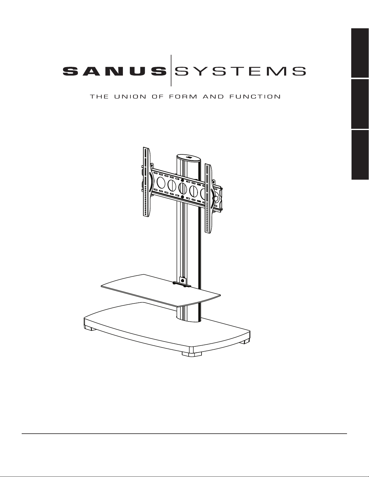
Assembly Instructions for Sanus Systems Platinum Furniture Model: PFFP
Thank you for choosing Sanus Systems Platinum Furniture. The PFFP is designed to support a 30” to 50” flat panel
television up to 130 lbs. If you have any questions regarding this or any other Sanus Systems product, please contact
us at 800.359.5520 or visit us at www.sanus.com. Our customer service representatives can assist you quickly with any
issues regarding assembly or missing parts. Check carefully to make sure none of the parts are missing or defective.
Never use defective parts. Replacement parts for products purchased from an authorized dealer will be shipped
directly to you. Please call Sanus Systems before returning products to the retail store where you purchased them.
Required Tools: Wrench or Socket Set, Phillips Screw Driver
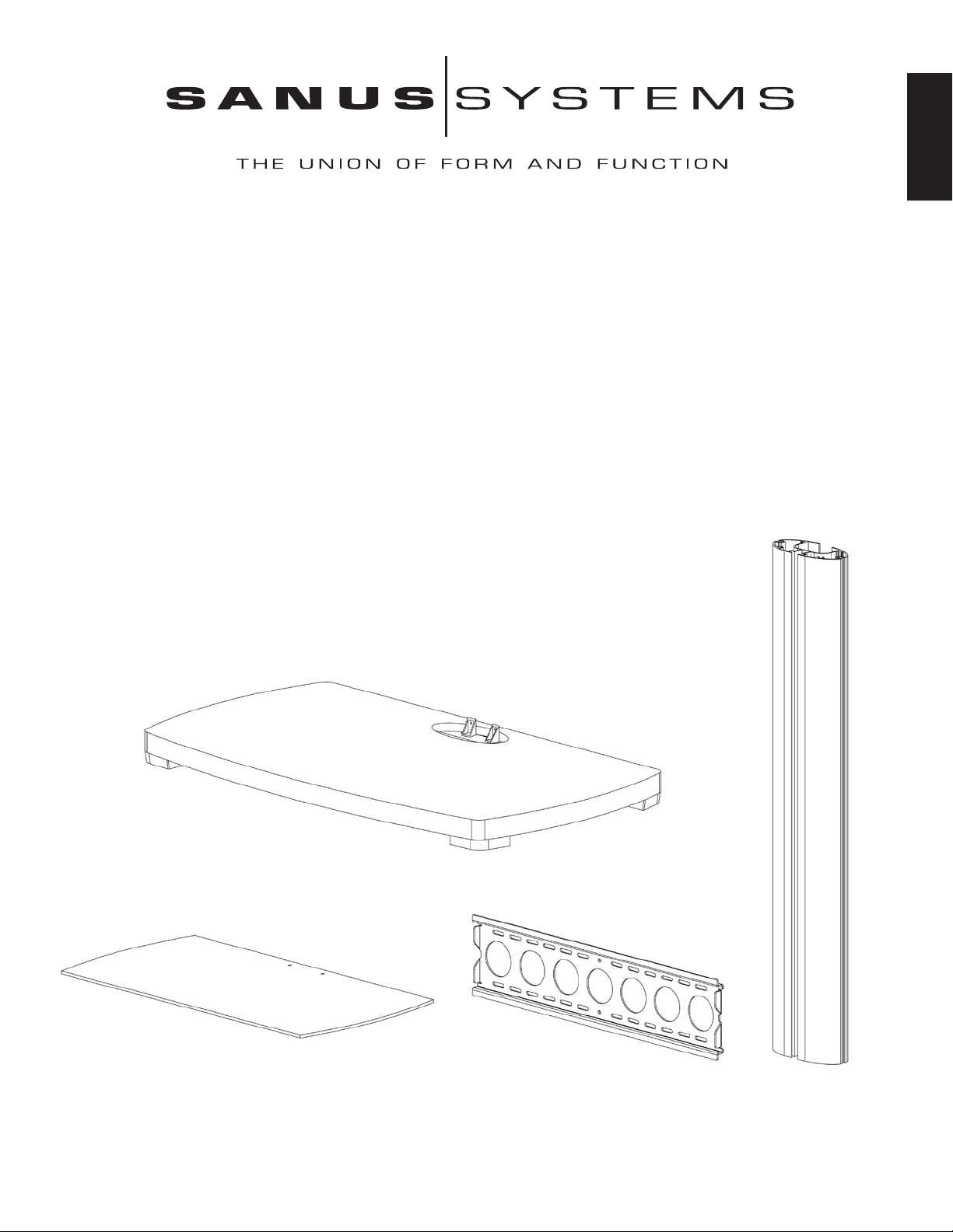
Supplied Parts:
(1) Base - a
(1) Glass Shelf - b
(1) Wall Bracket - c
(1) Pillar - d
(1) Shelf Plate - e
(1) Wall Plate - f
(1) Shelf Bracket - g
(1) Glass Shelf Washer - h
(2) Wall Bracket Spacer - i
(1) Top Cap - j
(1) Left Monitor Bracket - k
(1) Right Monitor Bracket - l
(2) M12 x 40 Bolt - m
(2) M12 Washer - n
(2) M8 x 35 Bolt - o
(2) M6 x 20 Bolt - p
(4) M8 Allen Bolt - q
(4) Spring Washer - r
(6) M8 Washer - s
(2) 1/4-20 Allen Bolt - t
(2) Plastic Washer - u
(4) M4 x 12 - v
(4) M4 x 30 - w
(4) M5 x 12 - x
(4) M5 x 30 - y
(4) M6 x 12 - z
(4) M6 x 35 - aa
(4) M8 x 16 - bb
(4) M8 x 40 - cc
(8) M4/M5 Washer - dd
(4) M4 Lock Washer - ee
(4) M5 Lock Washer - ff
(4) M6 Lock Washer - gg
(4) M8 Lock Washer - hh
(4) M4/M5 Spacer - ii
(4) M6/M8 Spacer - jj
(2) Safety Bolt - kk
(3) Allen Key - ll
ENGLISH
a
b c d
Page 4

ENGLISH
e f g h i j k l
m n o p
q r s t u
v w x y z aa
bb cc dd ee ff gg hh
ii jj kk ll
Page 5
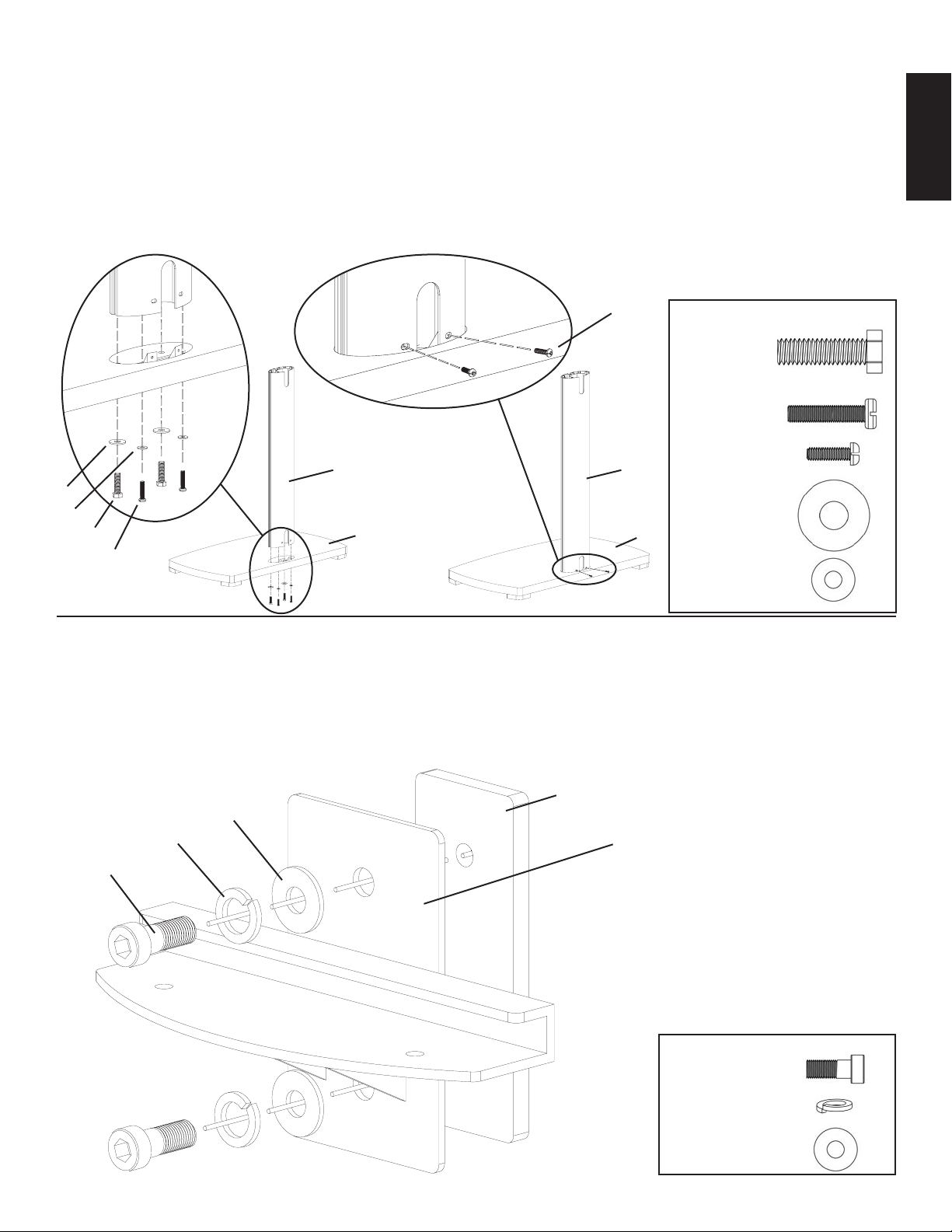
Step 1:
Attach the Pillar (d) to the Base (a) by placing each M12 x 40 Bolt (m) through an M12 Washer (n), each M8 x 35 Bolt
through an M8 Washer (s). Then thread each Bolt up through the Base and into the Pillar as shown in Diagram 1a. The M12
x 40 Bolts should be threaded into the front two holes of the Pillar, while the M8 x 35 Bolts should be threaded into the back
two holes of the Pillar. Tighten the M12 x 40 Bolts with a wrench, and tighten the M8 x 35 Bolts with a Phillips screw driver.
Proceed to insert two M6 x 20 Bolts (p) into the holes on the back of the Pillar as seen in Diagram 1b. Tighten the M6 x 20
Bolts with a Phillips screw driver.
Detailed View A Detailed View B
ENGLISH
p
d d
Required Hardware for Step 1
(2) M12 x 40
(2) M8 x 35
(2) M6 x 20
n
s
(2) M12 Washer
m a a
o
(2) M8 Washer
Diagram 1a Diagram 1b
Step 2:
Thread an M8 Allen Bolt (q) through a Spring Washer (r), an M8 Washer (s), the Shelf Bracket (g), and into the Shelf Plate
(e). See Diagram 2 for the proper assembly of these parts. Loosely tighten the M8 Allen Bolt into the Shelf Plate with an
Allen Key (ll). Leave approximately a 1/8” gap between the Shelf Bracket and the Shelf Plate for Step 4.
Diagram 2
e
s
r g
q
Required Hardware for Step 2
(2) M8 Allen Bolt
(2) Spring Washer
(2) M8 Washer
Page 6
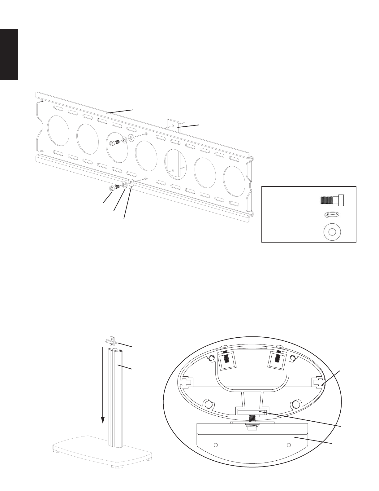
Step 3:
Thread an M8 Allen Bolt (q) through a Spring Washer (r), an M8 Washer (s), through the middle hole in the Wall Bracket
(c), and into the Wall Plate (f) as seen in Diagram 3. Loosely tighten the M8 Allen Bolt into the Wall Plate with an Allen Key
(ll). Leave approximately a 1/8” gap between the Wall Bracket and the Wall Plate for Step 5.
ENGLISH
Diagram 3
c
f
Required Hardware for Step 3
q
r
s
(2) M8 Allen Bolt
(2) Spring Washer
(2) M8 Washer
Step 4:
Add the Shelf Bracket Assembly to the Pillar (d) by sliding it down from the top to the desired position on the Pillar. Make
sure the Shelf Plate (e) fits into the channel in the Pillar. See the Top View of Diagram 4 for assistance. Once you have the
Shelf Bracket Assembly in place, proceed to tighten the M8 Allen Bolts (q) with an Allen Key (ll) so the Shelf Bracket Assembly is firmly in place.
Note: Make Sure The M8 Allen Bolts Are Tight!
Diagram 4 Top View
Shelf Bracket
Assembly
d d
e
g
Page 7
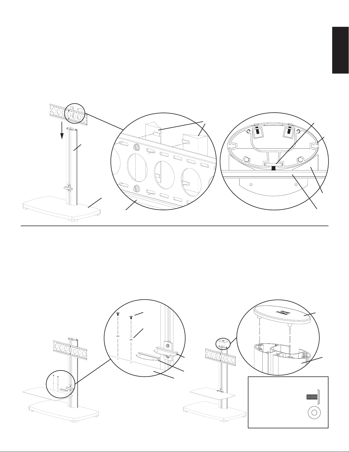
Step 5:
Attach the Wall Bracket Spacers (i) to the Wall Bracket (c) by fitting the plastic tabs into the correct oval holes on the Wall
Bracket as seen in the Detailed View of Diagram 5. Wall Bracket Spacers must be held in place while you slide the Wall
Bracket Assembly down into place on the Pillar (d). Make sure the Wall Plate (f) fits into the channel in the Pillar as seen in
the Top View of Diagram 5. Once the Wall Bracket Assembly is in the desired position, tighten the M8 Allen Bolts (q) with
an Allen Key (ll) so the Wall Bracket Assembly is firmly attached to the Pillar.
Note: Make Sure The M8 Allen Bolts Are Tight!
Diagram 5
Detailed View Top View
i f
d
d
ENGLISH
a i
c c
Step 6:
Take the Glass Shelf Washer (h) and insert it onto the Glass Shelf (b). Make sure the holes in the Glass Shelf Washer and the
Glass Shelf match up. Then, proceed to slide the Glass Shelf and the Glass Shelf Washer into the Shelf Bracket (g). Thread each
1/4-20 Allen Bolt (t) down through a Plastic Washer (u), the Glass Shelf, the Glass Shelf Washer, and into the Shelf Bracket.
Tighten the 1/4-20 Allen Bolt firmly so the Glass Shelf is secured to the Shelf Bracket. See Diagram 6a and Detailed View A
for assistance. Next, add the Top Cap (j) to the top of the Pillar (d) by lining up the two plastic dowels on the bottom of the Top
Cap with the corresponding pattern on the top of the Pillar as seen in Detailed View B of Diagram 6b. Press down firmly on the
Top Cap to make sure it is in place.
Detailed View A Detailed View B
t j
u
Diagram 6a Diagram 6b
g d
h
b
Note: Glass Shelf weight capacity is 50 lbs.
Required Hardware for Step 3
(2) 1/4-20 Allen Bolt
(2) Plastic Washer
Page 8

Step 7: Always make sure the television is unplugged before threading any bolt into the back panel!
Thread bolts carefully into your television by hand before tightening. If you feel resistance, remove the bolt immediately!
If you are unable to find appropriate hardware for your television, consult a local hardware store or call Sanus Systems.
Locate the threaded inserts on the back of your flat panel television and determine which of the provided Bolts
(v,w,x,y,z,aa,bb,cc) is the correct diameter. To test each diameter, thread the Bolts carefully into your television by hand
ENGLISH
until you find the diameter that correctly fits. Next, determine the correct length of the required Bolt. If the back of your TV
is flat, use one of the shorter Bolts without a Spacer. The back of some flat panel televisions are curved or have recessed
threaded inserts. This may require you to use one of the longer Bolts, and a Spacer (ii,jj) between the television and the
Monitor Bracket (k,l). Once you have the correct bolt selected, you can follow the diagrams below to see what additional
hardware you will need to mount the Monitor Brackets to your TV. Every Bolt will require a Lock Washer (ee,ff,gg,hh).
You will use four of each part every time it is listed below to attach the Monitor Brackets to your TV. For a TV with a flat
back, see Step 8 for installation instructions. For a TV with a curved back see Step 9. For a TV that has a back with recessed
threaded inserts see Step 10.
Hardware Diagrams:
M4 x 12
v w x y z aa bb cc
ee ee ff ff gg gg hh hh
dd dd dd dd jj jj
M4 x 30
M5 x 12
M5 x 30
M6 x 12
M6 x 35
M8 x 16
M8 x 40
ii ii
dd dd
Step 8: Attaching the Monitor Brackets to a TV with a flat back
For a flat back TV that requires the M4 or M5 diameter Bolt, thread a M4 x 12 (v) or a M5 x 12 (x) Bolt through the appropriate Lock Washer (ee,ff), an M4/M5 Washer (dd), the Monitor Bracket (k,l) and finally into the TV. See Detailed View
A of Diagram 8 for assistance. If your TV requires the M6 or M8 diameter Bolt thread a M6 x 12 (z) or a M8 x 16 (bb)
Bolt through the appropriate Lock Washer (gg,hh), through the Monitor Bracket and into the TV. See Detailed View B of
Diagram 8 for assistance. The Monitor Brackets should be vertically as close to center of the TV as possible. Lightly tighten
the knobs on the Monitor Brackets once they are properly connected to the TV.
Diagram 8 Detailed View A v, x
TV dd ee, ff
k, l
Knob
Detailed View B z, bb
gg, hh
TV
k, l
Page 9

Step 9: Attaching the Monitor Brackets to a TV with a curved back
If your TV has a curved back and requires either a M4 or M5 diameter bolt, thread a M4 x 30 (w) or a M5 x 30 (y) Bolt
through the appropriate Lock Washer (ee,ff), an M4/M5 Washer (dd), the Monitor Bracket (k,l), an M4/M5 Washer, a M4/
M5 Spacer (ii) and into the TV as seen in Detailed View A of Diagram 9. If you determined that your TV requires a Bolt
with a M6 or M8 Diameter, thread a M6 x 35 (aa) or a M8 x 40 (cc) Bolt through the appropriate Lock Washer (gg,hh), the
Monitor Bracket, a M6/M8 Spacer (jj) and into the TV as seen in Detailed View B of Diagram 9. The Monitor Brackets
should be vertically as close to the center of the TV as possible. Lightly tighten the knobs on the Monitor Brackets once they
are properly connected to the TV.
Detailed View A
Diagram 9
ii dd dd ee, ff w, y
TV
knob
Detailed View B
jj gg, hh aa,cc
ENGLISH
Step 10:
If your TV has threaded inserts that are recessed and requires either a M4 or M5 diameter bolt, thread a M4 x 30 (w) or a
M5 x 30 (y) Bolt through the appropriate Lock Washer (ee,ff), an M4/M5 Washer (dd), the Monitor Bracket (k,l), an M4/M5
Washer, a M4/M5 Spacer (ii) and into the TV as seen in Detailed View A of Diagram 10. If you determined that your TV
requires a Bolt with a M6 or M8 Diameter, thread a M6 x 35 (aa) or a M8 x 40 (cc) Bolt through the appropriate Lock Washer
(gg,hh), the Monitor Bracket, a M6/M8 Spacer (jj) and into the TV as seen in Detailed View B of Diagram 10. The Monitor
Brackets should be vertically as close to the center of the TV as possible. Lightly tighten knobs on the Monitor Brackets
once they are properly connected to the TV.
Detailed View A
TV
Diagram 10
ii dd dd ee, ff w, y
knob
Detailed View B
TV
jj aa, cc
gg, hh
Recessed Area
Page 10

Step 11: Lifting the television may require two people!
To hang the TV onto the Wall Bracket (c) first hook the Monitor Brackets (k,l) over the top of the Wall Bracket, then let the
bottom of the Monitor Brackets rotate in under the bottom of the Wall Bracket as shown in the Detailed View of Diagram 11.
Diagram 11 Detailed View
ENGLISH
k,l
d
TV
i
c
Step 12:
Insert the Safety Bolts (kk) into the threaded holes in the bottom of the Monitor Brackets (k,l) and tighten them with the
Allen Key (ll) so that they sit behind the bottom tab on the Wall Bracket (c) as shown in the Detailed View of Diagram 12.
Finally loosen the knobs on the Monitor Brackets and you are free to adjust your new flat panel TV.
Diagram 12 Detailed View
Knob
Bottom Tab on the
Wall Bracket
kk
k,l
Required Hardware for Step 12
(2) Safety Bolts
Page 11

L A U N I Ó N D E F O R M A Y F U N C I Ó N
Instrucciones de armado del mueble Platinum de Sanus Systems modelo: PFFP
Gracias por elegir el mueble Platinum de Sanus Systems. El modelo PFFP ha sido diseñado para soportar un televisor
con pantalla plana de 76,2 cm a 127 cm (30 a 50 pulg.) y un peso de hasta 59 kg (130 lb). Si tiene preguntas con
respecto a este u otros productos de Sanus Systems, llámenos al 800.359.5520 (en EE.UU.) o al 31 (0) 20 5708938
(en Europa). También nos puede visitar en nuestro sitio www.sanus.com. Nuestros representantes del servicio al
cliente le ayudarán oportunamente con cualquier duda que tenga en relación al armado o piezas faltantes. Revise
cuidadosamente para asegurarse de que no hayan piezas faltantes ni defectuosas. Nunca use piezas que presenten
algún defecto. Las piezas de repuesto para los productos comprados a través de un distribuidor autorizado se enviarán
directamente a usted. Sírvase llamar a Sanus Systems antes de devolver los productos a la tienda donde los compró.
Herramientas necesarias: Llave mecánica o juego de casquillos, destornillador Phillips
Piezas suministradas:
(1) Base - a
(1) Repisa de vidrio - b
(1) Soporte de pared - c
(1) Pilar - d
(1) Placa de repisa - e
(1) Placa de pared - f
(1) Soporte de repisa - g
(1) Arandela de repisa de pared - h
(2) Espaciador de soporte de pared - i
(1) Tapa superior - j
(1) Soporte izquierdo de monitor - k
(1) Soporte derecho de monitor - l
(2) Perno M12 x 40 - m
(2) Arandela M12 - n
(2) Perno M8 x 35 - o
(2) Perno M6 x 20 - p
(4) Perno allen M8 - q
(4) Arandela de resorte - r
(6) Arandela M8 - s
(2) Perno allen 1/4-20 - t
(2) Arandela de plástico - u
(4) M4 x 12 - v
(4) M4 x 30 - w
(4) M5 x 12 - x
(4) M5 x 30 - y
(4) M6 x 12 - z
(4) M6 x 35 - aa
(4) M8 x 16 - bb
(4) M8 x 40 - cc
(8) Arandela M4/M5 - dd
(4) Arandela de seguridad M4 - ee
(4) Arandela de seguridad M5 - ff
(4) Arandela de seguridad M6 - gg
(4) Arandela de seguridad M8 - hh
(4) Espaciador M4/M5 - ii
(4) Espaciador M6/M8 - jj
(2) Perno de seguridad - kk
(3) Llave allen - ll
ESPAÑOL
a
b c d
Page 12

e f g h i j k l
ESPAÑOL
m n o p
q r s t u
v w x y z aa
bb cc dd ee ff gg hh
ii jj kk ll
Page 13

Paso 1:
Conectar el pilar (d) en la base (a) pasando cada uno de los pernos M12 x 40 (m) por una arandela M12 (n) y cada uno de los
pernos M8 x 35 por una arandela M8 (s). Luego empezar a enroscar cada uno de los pernos por la base hasta llegar al pilar,
como se ilustra en el diagrama 1a. Los pernos M12 x 40 se deben enroscar en los dos agujeros delanteros del pilar, mientras
que los pernos M8 x 35 se deben enroscar en los dos agujeros traseros del pilar. Apretar los pernos M12 x 40 con una llave
mecánica y los pernos M8 x 35 con un destornillador Phillips. Proceder a insertar dos pernos M6 x 20 (p) en los agujeros en
la parte trasera del pilar, como se ilustra en el diagrama 1b. Apretar los pernos M6 x 20 con un destornillador Phillips.
Vista detallada A Vista detallada B
Tornillería requerida para el
p
paso 1
(2) M12 x 40
(2) M8 x 35
ESPAÑOL
d d
(2) M6 x 20
n
s
(2) Arandela M12
m a a
o
(2) Arandela M8
Diagrama 1a Diagrama 1b
Paso 2:
Pasar un perno allen M8 (q) por una arandela de resorte (r), una arandela M8 (s) y el soporte de repisa (g), hasta llegar a
la placa de repisa (e). Ver el diagrama 2 para el armado correcto de estas piezas. Apretar suavemente el perno allen M8 en
la placa de pared con una llave allen (ll). Dejar una separación de aproximadamente 0,3 cm (1/8 pulg.) entre el soporte de
repisa y la placa de repisa para el paso 4.
Diagrama 2
e
s
r g
q
Tornillería requerida para el paso 2
(2) Perno allen M8
(2) Arandela de resorte
(2) Arandela M8
Page 14

Paso 3:
Pasar un perno allen M8 (q) por una arandela de resorte (r), una arandela M8 (s), por el agujero central en el soporte de pared
(c), hasta llegar a la placa de pared (f), como se ilustra en el diagrama 3. Apretar suavemente el perno allen M8 en la placa
de pared con una llave allen (ll). Dejar una separación de aproximadamente 0,3 cm (1/8 pulg.) entre el soporte de pared y la
placa de pared para el paso 5.
Diagrama 3
c
f
ESPAÑOL
Tornillería requerida para el
paso 3
(2) Perno allen M8
q
r
s
(2) Arandela de resorte
(2) Arandela M8
Paso 4:
Agregar el conjunto de soporte de repisa al pilar (d) deslizándolo por la parte superior hasta alcanzar la posición deseada en
el pilar. Asegurarse de que la placa de repisa (e) encaje en la ranura del pilar. Ver la vista superior del diagrama 4 para más
ayuda. Una vez que se tiene el soporte de repisa en posición, proceder a apretar los pernos allen M8 (q) con una llave allen
(ll), de manera que el soporte quede bien asegurado en su lugar.
Nota: ¡Asegurarse de que los pernos allen M8 estén apretados!
Diagrama 4 Vista superior
Conjunto
Soporte de repisa
d d
e
g
Page 15

Paso 5:
Conectar los espaciadores de soporte de pared (i) en el soporte de pared (c) insertando las lengüetas de plástico en los
agujeros ovalados correctos en el soporte de pared, como se ilustra en el diagrama 5. Los espaciadores deben sujetarse en su
lugar mientras se desliza el soporte de pared en el pilar (d). Asegurarse de que la placa de pared (f) encaje en la ranura del
pilar, como se ilustra en la vista superior del diagrama 5. Una vez que el soporte de pared esté en la posición deseada, apretar
los pernos allen M8 (q) con una llave allen (ll), de manera que el soporte de pared quedé bien asegurado en el pilar.
Nota: ¡Asegurarse de que los pernos allen M8 estén apretados!
Diagrama 5
Vista detallada Vista superior
i f
d
d
ESPAÑOL
a i
c c
Paso 6:
Tomar la arandela para repisa de vidrio (h) e insertarla en la repisa de vidrio (b). Asegurarse de que los agujeros en la arandela
y la repisa coincidan. Luego, proceder a deslizar la repisa de vidrio y la arandela en el soporte de repisa (g). Pasar cada perno
allen 1/4-20 (t) por una arandela de plástico (u), la repisa de vidrio y la arandela para repisa de vidrio, hasta llegar al soporte de
repisa. Apretar el perno allen 1/4-20 firmemente de manera que la repisa de vidrio quede bien asegurada al soporte de repisa.
Ver el diagrama 6a y la vista detallada para más ayuda. Luego, poner la tapa superior (j) encima del pilar (d) alineando las dos
clavijas de plástico en la parte inferior de la tapa con el patrón correspondiente en la parte superior del pilar, como se muestra
en la vista detallada B del diagrama 6b. Presionar firmemente sobre la tapa para asegurarse que quede bien en su lugar.
Vista detallada A Vista detallada B
t j
u
Diagrama 6a Diagrama 6b
g d
h
b
Tornillería requerida para
el paso 3
(2) Perno allen 1/4-20
(2) Arandela de plástico
Nota: La capacidad de peso de la repisa de vidrio es de 22,7 kg (50 lb).
Page 16

Paso 7: ¡Siempre asegurarse que el televisor esté desenchufado antes de pasar cualquier perno por el panel trasero!
Cuidadosamente enroscar los pernos a mano antes de apretarlos en el televisor. ¡Si siente alguna resistencia, retirar el perno
inmediatamente! Si no puede encontrar la tornillería correcta para su televisor, consultar en una ferretería local o llamar a Sanus
Systems.
Ubicar los insertos roscados en la parte trasera del televisor con pantalla plana, y determinar cuál de los pernos suministrados (v, w, x, y, z,
aa, bb, cc) es el de diámetro correcto. Para probar el diámetro, enroscar los pernos a mano en el televisor hasta encontrar el diámetro que
encaje correctamente. Luego, determinar el largo correcto del perno requerido. Si la parte trasera del televisor es plana, usar un perno corto
sin espaciador. La parte trasera de algunos televisores es curva o bien tiene insertos roscados. Esto puede requerir el uso de pernos más
largos y un espaciador (ii, jj) entre el televisor y el soporte del monitor (k, l). Una vez que se tenga seleccionado el perno correcto, se pueden
seguir los diagramas de más abajo para ver la tornillería adicional que se necesitará para montar los soportes de monitor en el televisor. Cada
perno requerirá una arandela de seguridad (ee, ff, gg, hh). Se necesitarán cuatro de cada una de las piezas listadas más abajo para conectar
los soportes de monitor al televisor. Para un televisor con la parte trasera plana, ver el paso 8 para las instrucciones de instalación. Para un
ESPAÑOL
televisor con la parte trasera curva, ver el paso 9. Para un televisor que tenga la parte trasera con insertos roscados, ver el paso 10.
Diagramas de tornillería:
M4 x 12
M4 x 30
M5 x 12
M5 x 30
M6 x 12
M6 x 35
M8 x 16
M8 x 40
v w x y z aa bb cc
ee ee ff ff gg gg hh hh
dd dd dd dd jj jj
ii ii
dd dd
Paso 8: Conexión de los soportes de monitor a un televisor con la parte trasera plana
Para un televisor con la parte trasera plana que requiere el perno M4 ó M5, pasar un perno M4 x 12 (v) o M5 x 12 (x) por la
arandela de seguridad correspondiente (ee, ff), una arandela M4/M5 (dd) y el soporte de monitor (k, l), hasta llegar finalmente al
televisor. Ver la vista detallada A del diagrama 8 para más ayuda. Si su televisor requiere el perno M6 ó M8, pasar un perno M6 x
12 (z) o M8 x 16 (bb) por la arandela de seguridad correspondiente (gg, hh) y el soporte de monitor, hasta llegar al televisor. Ver
la vista detallada B del diagrama 8 para más ayuda. Los soportes de monitor deben quedar de manera vertical, lo más cerca posible
al centro del televisor. Apretar levemente las perillas en los soportes de monitor una vez que queden bien conectadas al televisor.
Diagrama 8
Vista detallada A v, x
TV dd ee, ff
k, l
Perilla
Vista detallada B z, bb
gg, hh
TV
k, l
Page 17

Paso 9: Conexión de los soportes de monitor a un televisor con la parte trasera curva
Si el televisor tiene la parte trasera curva y requiere un perno M4 ó M5, pasar un perno M4 x 30 (w) o M5 x 30 (y) por la
arandela de seguridad correspondiente (ee, ff), una arandela M4/M5 (dd), el soporte de monitor (k, l), una arandela M4/M5, un
espaciador M4/M5 (ii) y finalmente el televisor, como se ilustra en la vista detallada A del diagrama 9. Si se determina que el
televisor requiere un perno con diámetro M6 ó M8, pasar un perno M6 x 35 (aa) o M8 x 40 (cc) por la arandela de seguridad
correspondiente (gg, hh), el soporte de monitor, un espaciador M6/M8 (jj) y finalmente el televisor, como se ilustra en la
vista detallada B del diagrama 9. Los soportes de monitor deben quedar de manera vertical, lo más cerca posible al centro del
televisor. Apretar levemente las perillas en los soportes de monitor una vez que queden bien conectadas al televisor.
Vista detallada A
Diagrama 9
ii dd dd ee, ff w, y
TV
Vista detallada B
perilla jj gg, hh aa,cc
ESPAÑOL
Paso 10:
Si el televisor tiene la parte trasera con insertos roscados y requiere un perno de diámetro M4 ó M5, pasar un perno M4 x 30
(w) o M5 x 30 (y) por la arandela de seguridad correspondiente (ee, ff), una arandela M4/M5 (dd), el soporte de monitor (k, l),
una arandela M4/M5, un espaciador M4/M5 (ii) y finalmente el televisor, como se ilustra en la vista detallada A del diagrama
10. Si se determina que el televisor requiere un perno con diámetro M6 ó M8, pasar un perno M6 x 35 (aa) o M8 x 40 (cc) por
la arandela de seguridad correspondiente (gg, hh), el soporte de monitor, un espaciador M6/M8 (jj) y finalmente el televisor,
como se ilustra en la vista detallada B del diagrama 10. Los soportes de monitor deben quedar de manera vertical, lo más cerca
posible al centro del televisor. Apretar levemente las perillas en los soportes de monitor una vez que queden bien conectadas al
televisor.
Vista detallada A
TV
Diagrama 10
ii dd dd ee, ff w, y
Vista detallada B
TV
jj aa, cc
perilla gg, hh
Área hendida
Page 18

Paso 11: ¡Se requieren dos personas para levantar el televisor!
Para colgar el televisor en el soporte de pared (c) primero enganchar los soportes de monitor (k, l) en la parte superior del
soporte de pared, luego dejar que la parte inferior de los soportes de monitor giren debajo de la base del soporte de pared,
como se ilustra en la vista detallada del diagrama 11.
Diagrama 11 Vista detallada
k, l
d
TV
ESPAÑOL
i
c
Paso 12:
Insertar los pernos de seguridad (kk) en los agujeros roscados que se encuentran en la base de los soportes de monitor (k, l) y
apretarlos con una llave allen (ll), de manera que se asienten detrás de la lengüeta inferior del soporte de pared (c), como se ilustra
en la vista detallada del diagrama 12. Finalmente, aflojar las perillas en los soportes de monitor y ajustar libremente el televisor.
Diagrama 12 Vista detallada
Perilla
Lengüeta inferior en el
soporte de pared
kk
k, l
Tornillería requerida para el paso 12
(2) Pernos de seguridad
Page 19

L’ U N I O N D E L A F O R M E E T D E L A F O N C T I O N
Instructions d’assemblage pour le modèle de mobilier Platine de Sanus Systems : PFFP
Nous vous remercions d’avoir choisi le mobilier Platine de Sanus Systems. Le PFFP est conçu pour soutenir un
téléviseur à écran plat de 76,2 cm à 127 cm (30 po à 50 po) pesant jusqu’à 59 kg (130 lb). Si vous ne comprenez pas
ces instructions ou si vous avez un doute quant à la sécurité de cette installation, veuillez faire appel à un technicien
qualifié ou communiquez avec Sanus en composant le 1-800-359-5520 (aux É.-U.), ou le 31 (0) 20 5708938 (pour
l’Europe). Vous pouvez aussi allez sur notre site Web au www.sanus.com. Les représentants de notre service à la
clientèle pourront répondre rapidement à toutes vos questions concernant l’assemblage ou les pièces manquantes.
Vérifiez soigneusement qu’aucune pièce n’est manquante ou défectueuse. N’utilisez jamais de pièces défectueuses.
Les pièces de rechange de produits achetés auprès d’un distributeur agréé vous seront livrées directement. Veuillez
communiquer avec Sanus Systems avant de retourner les produits au magasin de détail où vous les avez achetés.
Outils nécessaires : Jeu de clés ou de douilles, tournevis cruciforme
Pièces fournies :
(1) Base - a
(1) Etagère en verre - b
(1) Support de fixation - c
(1) Colonne - d
(1) Plaque pour étagère - e
(1) Plaque murale - f
(1) Support pour étagère - g
(1) Rondelle pour étagère en verre - h
(2) Entretoise du support de fixation - i
(1) Capuchon supérieur - j
(1) Support gauche du moniteur - k
(1) Support droit du moniteur - l
(2) Boulon M12 x 40 - m
(2) Rondelle M12 - n
(2) Boulon M8 x 35 - o
(2) Boulon M6 x 20 - p
(4) Vis Allen M8 - q
(4) Rondelle à ressort - r
(6) Rondelle M8 - s
(2) Vis Allen 1/4-20 - t
(2) Rondelle en plastique - u
(4) M4 x 12 - v
(4) M4 x 30 - w
(4) M5 x 12 - x
(4) M5 x 30 - y
(4) M6 x 12 - z
FRANÇAIS
(4) M6 x 35 - aa
(4) M8 x 16 - bb
(4) M8 x 40 - cc
(8) Rondelle M4/M5 - dd
(4) Rondelle-frein M4 - ee
(4) Rondelle-frein M5 - ff
(4) Rondelle-frein M6 - gg
(4) Rondelle-frein M8 - hh
(4) Entretoise M4/M5 - ii
(4) Entretoise M6/M8 - jj
(2) Boulon de sécurité - kk
(3) Clé Allen - ll
a
b c d
Page 20

e f g h i j k l
m n o p
FRANÇAIS
q r s t u
v w x y z aa
bb cc dd ee ff gg hh
ii jj kk ll
Page 21

Etape 1 :
Fixez la colonne (d) à la base (a) en plaçant chaque boulon M12 x 40 (m) dans une rondelle M12 (n), et chaque boulon M8 x
35 dans une rondelle M8 (s). Ensuite, faites passer chaque boulon à travers la base et la colonne, tel qu’illustré sur le schéma
1a. Les boulons M12 x 40 devraient être insérés dans les deux trous avant de la colonne, alors que les boulons M8 x 35
devraient être insérés dans les deux trous arrière de la colonne. Resserrez les boulons M12 x 40 avec une clé et les boulons
M8 x 35 avec un tournevis cruciforme. Insérez ensuite les deux boulons M6 x 20 (p) dans les trous situés à l’arrière de la
colonne, tel qu’illustré au schéma 1b. Serrez les boulons M6 x 20 avec un tournevis cruciforme.
Vue détaillée A Vue détaillée B
p
d d
Matériel requis pour l’étape 1
(2) M12 x 40
(2) M8 x 35
(2) M6 x 20
n
s
(2) Rondelle M12
m a a
o
(2) Rondelle M8
Schéma 1a Schéma 1b
Etape 2 :
Faites passer une vis Allen M8 (q) dans une rondelle à ressort (r), une rondelle M8 (s) et un support pour étagère (g), puis
dans la plaque pour étagère (e). Voir le schéma 2 pour le bon assemblage de ces pièces. Insérez la vis Allen M8, sans trop la
serrer, dans la plaque pour étagère à l’aide de la clé Allen (ll). Laissez un jeu d’environ 0,3 cm (1/8 po) entre le support pour
étagère et la plaque pour étagère, en vue de l’étape 4.
Schéma 2
e
s
r g
q
FRANÇAIS
Matériel requis pour l’étape 2
(2) Vis Allen M8
(2) Rondelle à ressort
(2) Rondelle M8
Page 22

Etape 3 :
Faites passer une vis Allen M8 (q) dans une rondelle à ressort (r) et une rondelle M8 (s) et passez-les dans le trou du milieu
du support de fixation (c), puis dans la plaque murale (f), tel qu’illustré sur le schéma 3. Insérez la vis Allen M8, sans trop la
serrer, dans la plaque murale à l’aide de la clé Allen (ll). Laissez un jeu d’environ 0,3 cm (1/8 po) entre le support de fixation
et la plaque murale, en vue de l’étape 5.
Schéma 3
c
f
Matériel requis pour l’étape 3
q
r
s
FRANÇAIS
(2) Vis Allen M8
(2) Rondelle à ressort
(2) Rondelle M8
Etape 4 :
Ajoutez l’assemblage du support pour étagère à la colonne (d) en le glissant sur celle-ci à partir du haut jusqu’à la position
désirée. Assurez-vous que la plaque pour étagère (e) s’adapte bien au canal de la colonne. Reportez-vous à la vue du dessus
du schéma 4 si vous avez besoin d’aide. Une fois l’assemblage du support pour étagère en place, serrez les vis Allen M8 (q)
à l’aide d’une clé Allen (ll) afin que l’assemblage soit fermement maintenu.
Remarque : Assurez-vous que les vis Allen M8 sont bien serrées !
Schéma 4 Vue du dessus
Assemblage
du support pour étagère
d d
e
g
Page 23

Etape 5 :
Fixez les entretoises du support de fixation (i) au support de fixation (c) en plaçant les capuchons en plastique en face des
trous ovales correspondants sur le support de fixation, tel qu’illustré sur la vue détaillée du schéma 5. Les entretoises du
support de fixation doivent être maintenues pendant que vous faites glisser l’assemblage du support de fixation jusqu’à sa
place spécifique sur la colonne (d). Assurez-vous que la plaque murale (f) s’adapte bien au canal de la colonne, tel qu’illustré
sur la vue du dessus du schéma 5. Une fois l’assemblage du support de fixation dans la position désirée, serrez les vis Allen
M8 (q) à l’aide d’une clé Allen (ll) afin que l’assemblage soit fermement fixé à la colonne.
Remarque : Assurez-vous que les vis Allen M8 sont bien serrées !
Schéma 5
Vue détaillée Vue du dessus
i f
d
d
FRANÇAIS
a i
c c
Etape 6 :
Prenez la rondelle pour étagère en verre (h) et placez-la sur l’étagère en verre (b). Assurez-vous que les trous de la rondelle pour
étagère en verre et de l’étagère en verre sont alignés. Ensuite, faites glisser l’étagère en verre et la rondelle pour étagère en verre dans le
support pour étagère (g). Faites passer chacune des vis Allen 1/4-20 (t) dans une rondelle en plastique (u), puis dans l’étagère en verre
et dans la rondelle pour l’étagère en verre, et faites passer le tout dans le support pour étagère. Serrez les vis Allen 1/4-20 fermement,
afin que l’étagère en verre soit bien fixée au support pour étagère. Reportez-vous au schéma 6a et à la vue détaillée A si vous avez
besoin d’aide. Par la suite, mettez le capuchon supérieur (j) sur le dessus de la colonne (d) en alignant les deux goujons de plastique
situés au-dessous du capuchon supérieur selon la configuration correspondante sur le dessus de la colonne, tel qu’illustré sur la vue
détaillée B du schéma 6b. Appuyez fermement sur le capuchon supérieur pour vous assurer qu’il est bien en place.
Vue détaillée A Vue détaillée B
t j
u
Schéma 6a Schéma 6b
g d
h
b
Remarque : L’étagère en verre a une capacité de charge de 22,7 kg (50 lb).
Matériel requis pour l’étape 3
(2) Vis Allen 1/4-20
(2) Rondelle en plastique
Page 24

Etape 7 :Assurez-vous que le téléviseur est débranché avant de visser les boulons sur le panneau arrière !
Vissez les vis à la main et avec précaution dans votre téléviseur avant de les serrer définitivement. Si vous ressentez une
résistance quelconque, enlevez immédiatement la vis ! Si vous ne trouvez pas la visserie appropriée à votre téléviseur,
consultez une quincaillerie locale ou contactez directement Sanus Systems.
Repérez les inserts filetés sur le panneau arrière du téléviseur à écran plat et déterminez quels boulons ont le diamètre approprié (v, w, x, y,
z, aa, bb, cc). Pour tester tous les diamètres, serrez avec précaution les boulons à la main dans votre téléviseur jusqu’à ce que vous trouviez
le diamètre convenable. Déterminez ensuite la longueur de boulon appropriée. Si le panneau arrière de votre téléviseur est plat, utilisez
l’un des boulons les plus courts, sans entretoise. Le panneau arrière de certains téléviseurs à écran plat est courbé ou doté d’inserts filetés
renfoncés. Dans ce cas, vous aurez peut-être besoin de mettre les boulons les plus longs et une entretoise (ii, jj) entre la télévision et le
support du moniteur (k, l). Après avoir choisi le boulon approprié, vous pouvez suivre les schémas ci-dessous afin de déterminer la visserie
supplémentaire nécessaire au montage des supports du moniteur à votre téléviseur. Chaque boulon nécessite une rondelle-frein (ee, ff, gg,
hh). Vous aurez besoin de quatre de chacune des pièces qui sont répertoriées ci-dessous pour fixer les supports du moniteur à votre téléviseur.
Pour un téléviseur à panneau arrière plat, voir les instructions d’installation à l’étape 8. Pour un téléviseur à panneau arrière courbé, voir
l’étape 9. Pour un téléviseur à panneau arrière doté d’inserts filetés renfoncés, voir l’étape 10.
Schémas de la visserie :
M4 x 12
M4 x 30
M5 x 12
M5 x 30
M6 x 12
M6 x 35
M8 x 16
M8 x 40
v w x y z aa bb cc
ee ee ff ff gg gg hh hh
dd dd dd dd jj jj
ii ii
FRANÇAIS
dd dd
Etape 8 : Fixation des supports du moniteur sur un téléviseur à panneau arrière plat
Si le téléviseur à panneau arrière plat requiert l’utilisation d’un boulon M4 ou M5, faites passez un boulon M4 x 12 (v) ou M5 x 12 (x)
par la rondelle-frein appropriée (ee, ff), une rondelle M4/M5 (dd), le support du moniteur (k, l) et vissez-le dans le téléviseur. Reportezvous à la vue détaillée A du schéma 8 si vous avez besoin d’aide. Si votre téléviseur requiert l’utilisation d’un boulon M6 ou M8, faites
passer un boulon M6 x 12 (z) ou M8 x 16 (bb) par la rondelle-frein appropriée (gg, hh), par le support du moniteur et vissez-le dans le
téléviseur. Reportez-vous à la vue détaillée B du schéma 8 si vous avez besoin d’aide. Les supports de moniteur devraient être placés
verticalement aussi près que possible du centre du téléviseur. Resserrez légèrement les boutons sur les supports du moniteur après qu’ils
aient été convenablement branchés au téléviseur.
Schéma 8 Vue détaillée A v, x
Téléviseur dd ee, ff
k, l
Bouton
Vue détaillée B z, bb
gg, hh
Téléviseur
k, l
Page 25

Etape 9 : Fixation des supports du moniteur sur un téléviseur à panneau arrière courbé
Si le téléviseur à panneau arrière courbé requiert l’utilisation d’une vis M4 ou M5, faites passer un boulon M4 x 30 (w) ou M5 x 30 (y)
par la rondelle-frein appropriée (ee, ff), une rondelle M4/M5 (dd), le support du moniteur (k, l), une rondelle M4/M5, une entretoise
M4/M5 (ii) et vissez-le dans le téléviseur tel qu’illustré sur la vue détaillée A du schéma 9. Si votre téléviseur requiert l’utilisation d’un
boulon M6 ou M8, faites passer le boulon M6 x 35 (aa) ou M8 x 40 (cc) par la rondelle-frein appropriée (gg, hh), le support du moniteur,
une entretoise M6/M8 (jj) et vissez-le dans le téléviseur tel qu’illustré sur la vue détaillée B du schéma 9. Les supports du moniteur
devraient être placés verticalement aussi près que possible du centre du téléviseur. Resserrez légèrement les boutons sur les supports du
moniteur après qu’ils aient été convenablement branchés au téléviseur.
Vue détaillée A
Schéma 9
ii dd dd ee, ff w, y
Téléviseur
bouton
Vue détaillée B
jj gg, hh aa, cc
Etape 10 :
Si votre téléviseur a des inserts filetés renfoncés qui requièrent l’utilisation d’un boulon M4 ou M5, faites passer un boulon
M4 x 30 (w) ou M5 x 30 (y) par la rondelle-frein appropriée (ee, ff), une rondelle M4/M5 (dd), le support du moniteur (k,
l), une rondelle M4/M5, une entretoise M4/M5 (ii) et vissez-le dans le téléviseur tel qu’illustré sur la vue détaillée A du
schéma 10. Si votre téléviseur requiert l’utilisation d’un boulon M6 ou M8, faites passer un boulon M6 x 35 (aa) ou M8
x 40 (cc) par la rondelle-frein appropriée (gg, hh), le support du moniteur, une entretoise M6/M8 (jj) et vissez-le dans le
téléviseur tel qu’illustré sur la vue détaillée B du schéma 10. Les supports de moniteur devraient être placés verticalement
aussi près que possible du centre du téléviseur. Resserrez légèrement les boutons sur les supports du moniteur après qu’ils
ont été convenablement branchés au téléviseur.
Vue détaillée A
Téléviseur
Schéma 10
ii dd dd ee, ff w, y
FRANÇAIS
bouton
Vue détaillée B
Téléviseur
jj aa, cc
gg, hh
Zone renfoncée
Page 26

Etape 11 : L’intervention de deux personnes sera possiblement nécessaire pour soulever le téléviseur !
Pour suspendre le téléviseur au support de fixation (c), accrochez d’abord les supports du moniteur (k, l) au-dessus du
support de fixation, puis laissez le bas des supports du moniteur pivoter sous le bas du support de fixation, tel qu’illustré
sur la vue détaillée du schéma 11.
Schéma 11 Vue détaillée
k, l
d
Téléviseur
i
c
FRANÇAIS
Etape 12 :
Insérez les boulons de sécurité (kk) dans les trous filetés au bas des supports du moniteur (k, l) et serrez-les à l’aide d’une clé Allen (ll)
pour qu’ils se trouvent derrière la patte inférieure du support de fixation (c) tel qu’illustré sur la vue détaillée du schéma 12. Desserrez
enfin les boutons sur les supports du moniteur et vous pouvez à présent régler librement votre nouveau téléviseur à écran plat.
Schéma 12 Vue détaillée
Bouton
Patte arrière sur le
support de fixation
kk
k, l
Matériel requis pour l’étape 12
(2) Boulon de sécurité
 Loading...