

Page 1
LA112
(6901-100189 <01>)
Backed by CLO
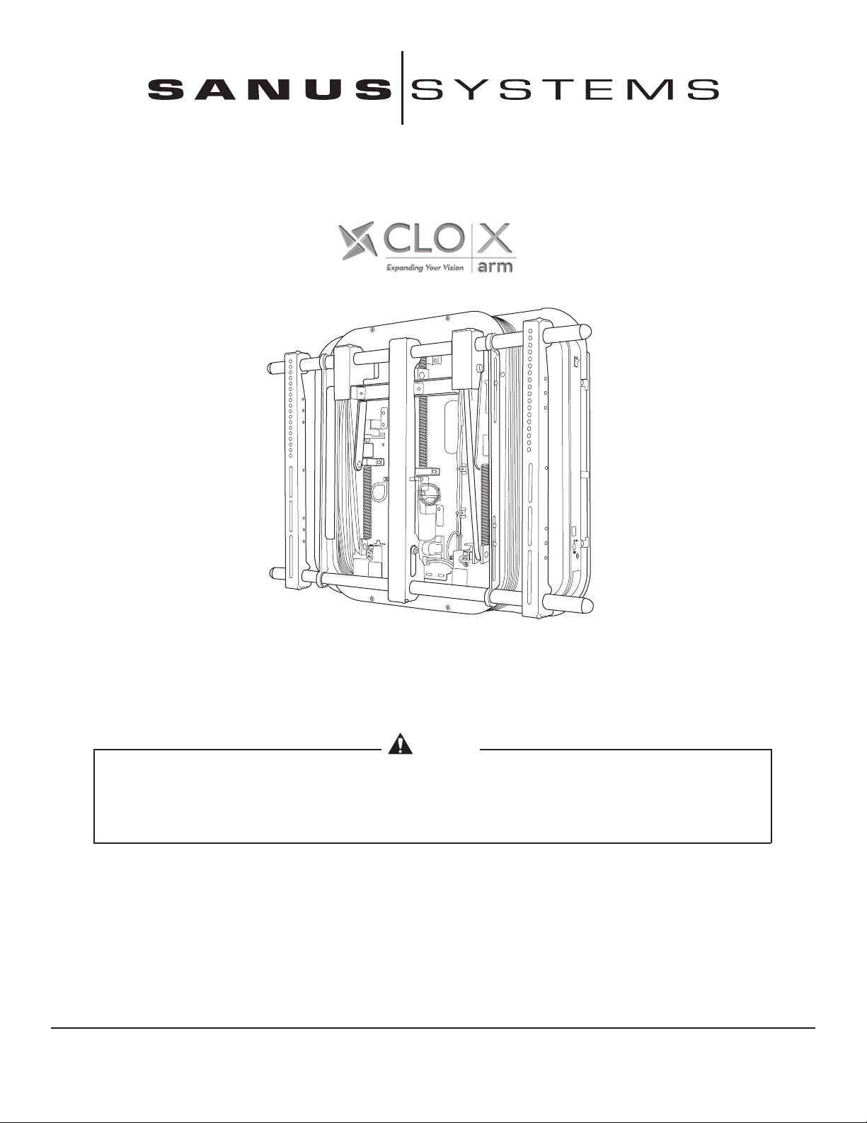
Thank you for choosing the Sanus Systems LA112 motorized mount. The LA112 is a remote-controlled automated
mount for flat panel monitors designed to be fully adjustable. The LA112 supports flat panel monitors with a
maximum weight of 81 kg (180 lbs.), ranging in size from 40 in. – 63 in. (102 cm – 106 cm). The LA112 extends up to
12 in (30 cm) from the wall.
CAUTION
Do not use this product for any purpose not explicitly specified by Sanus Systems. Improper installation may
cause property damage or personal injury. If you do not understand these directions, or have doubts about
the safety of the installation, contact Sanus Systems Customer Service or call a qualified contractor. Sanus
Systems is not liable for damage or injury caused by incorrect mounting, assembly, or use.
Sanus Systems 2221 Hwy 36 West, Saint Paul, MN 55113 USA
Customer Service: 1-800-359-5520 • info@sanus.com • www.sanus.com
Page 2
OPT
3/8
1/8 in. 1/2 in.
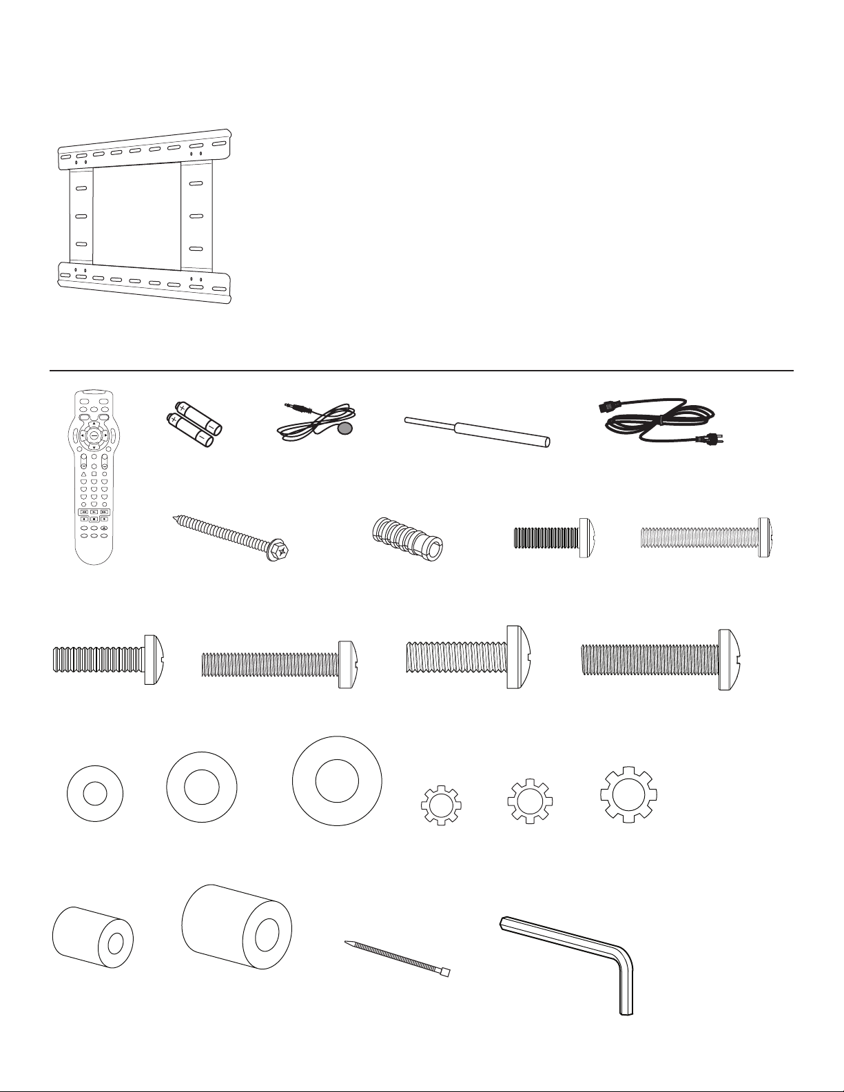
Supplied Parts and Hardware
Before starting assembly, verify all parts are included and undamaged. If any parts are missing or damaged, do not return the item
to your dealer; contact Sanus Systems Customer Service. Never use damaged parts!
WARNING
This product contains small items that could be a choking hazard if swallowed. Keep these items away from
young children!
Adapters are not included with the LA112. If you need an adapter, contact Sanus Systems Customer Service at
1-800-359-5520 or email us at info@sanus.com. You may also visit our website: www.sanus.com
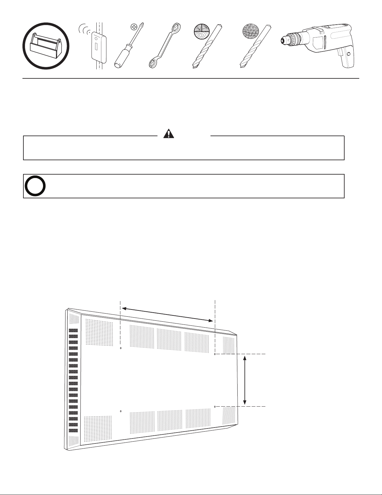
Determine if your monitor will require adapters to fit the LA112. Measure the distance between the mounting holes on the
back of the monitor.
For monitors with hole patterns less than 21.5 inches (54.6 cm) wide, install Cross Plate adapters.
For monitors with hole patterns 26 - 34.5 inches (66 - 87.6 cm) wide, install Bar Extension
adapters.
Measure width
between holes
For monitors 18.5 - 27.5 inches
(47 - 70 cm) high, install
Bracket Extension adapters.
Measure height
between holes
6901-100189 <01>
Page 3
P1
P3
VOL
+
CH
TV
SET
X-ARM
VCR
DVD
CBL
SEL
IN/OUT
P
R
E
S
E
T
MENU
EXIT
MUTE
FAV
1 2 3
4 5 6
7 8 9
0
P2
P4
+
M6 x 35mm
M6 / M8
M5 x 16 mm
M5 x 30mm
M6 x 35mm
M8 x 35mm
M8
M6
M8x20
M6 x 18mm
M4/M5
M6 / M8
M5
M8
M4/M5
M6/M8
NOTE: Items [1] through [4] are pre-assembled.
[09] x 1
[14] x 4
[05] x 2
[10] x 6
[06] x 1
[15] x 4
[02] x 1[01] x 1
[03] x2
[07] x 1
[11] x 6
[12] x 4
[16] x 4
[04] x 4
[08] x 1
[13] x 4
[17] x 4
[18] x 4
[24] x 4
6901-100189 <01>
[19] x 4
[25] x 4
[20] x 4
[21] x 4
[26] x 10
[22] x 4
[27] x 1
[23] x 4
Page 4
CAUTION
Avoid potential injuries or damage to equipment. The LA112 is designed to mount to vertical walls only.
Do not attempt to mount the LA112 to ceilings or non-vertical walls. For indoor use only! Do not mount
outdoors.
CAUTION
Avoid potential injuries or damage to equipment! Always observe the LA112 while in motion. To stop the
motion, press any of the arrow keys on the remote control. Never allow children to operate the LA112.
CAUTION
Avoid potential injuries or damage to equipment! Do not operate the LA112 unless all protective covers and
guards are in place. Keep away from moving parts.
CAUTION
Avoid damage to equipment! Use only accessories distributed or recommended by Sanus Systems. Do
not operate the LA112 if the appliance has malfunctioned, or has been damaged in any way; return to an
authorized service facility for inspection.
CAUTION
Avoid potential injuries or damage to equipment! The LA112 must be connected to a grounded outlet.
Disconnect the LA112 when not in use, or before cleaning or servicing the unit. To disconnect the LA112, turn
off all controls then remove the plug from the outlet.
CAUTION
Do not unplug by pulling on cord. To uplug, grasp the plug, not the cord.
6901-100189 <01>
Page 5
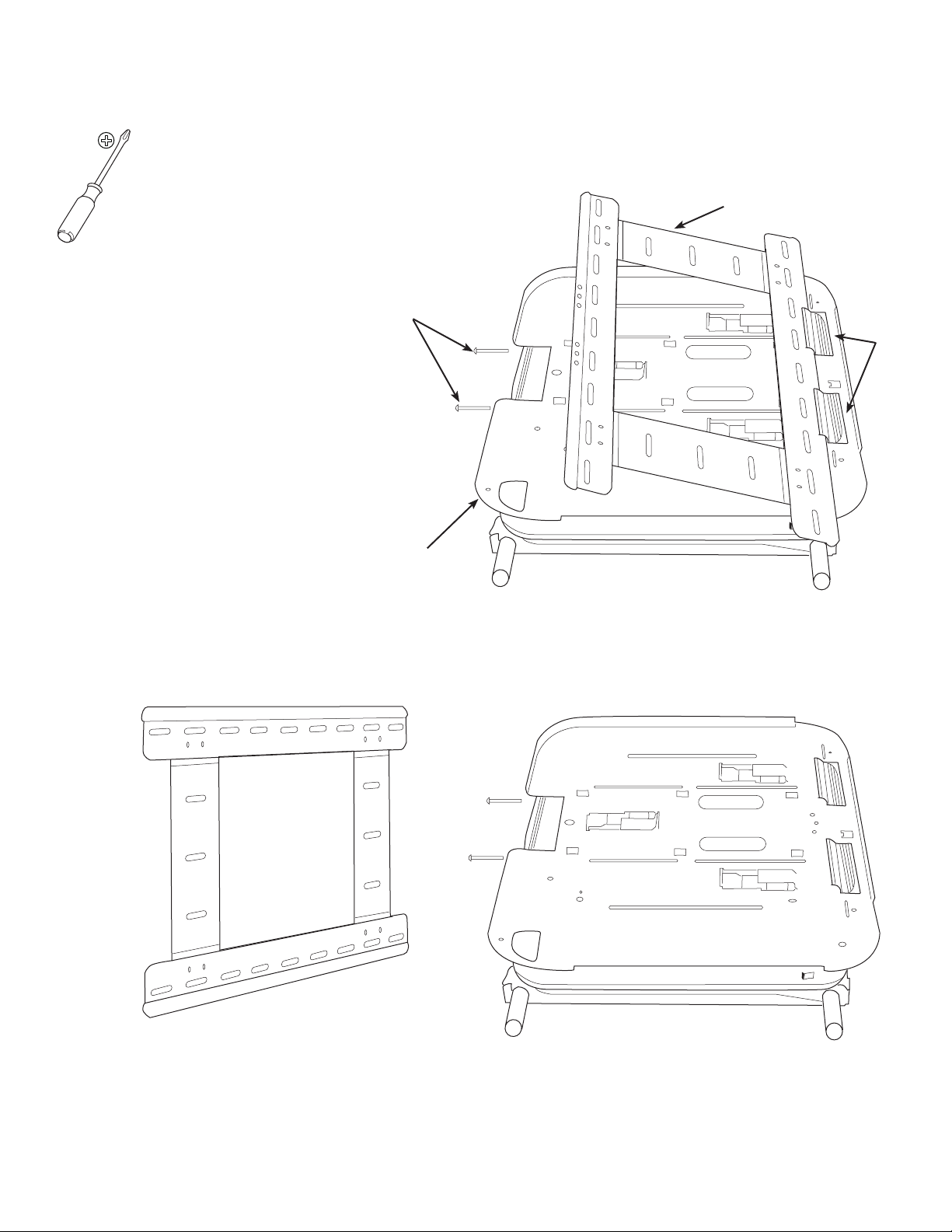
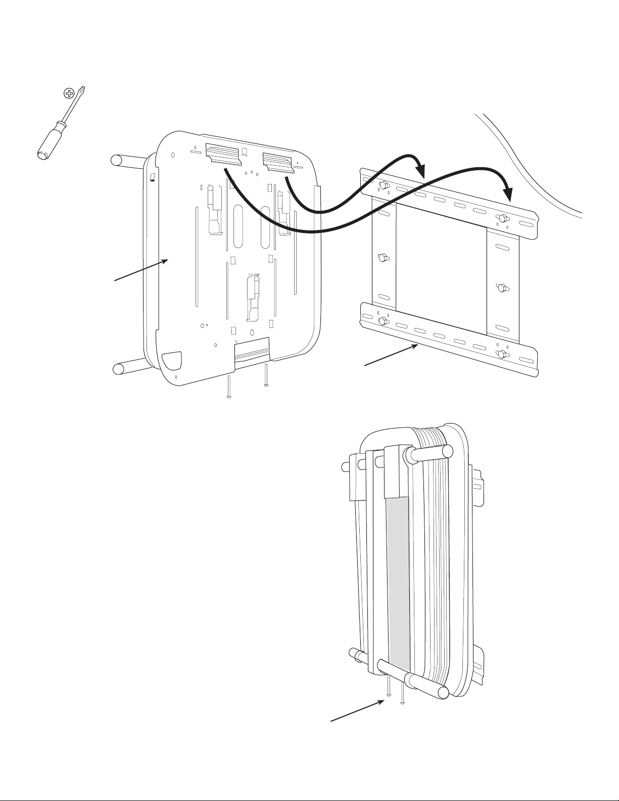
1: Remove Wall Plate from Arm
The LA112 is shipped with the wall plate and arm
assembled. You must remove the wall plate before
installation.
Loosen the two fasteners [A] securing the wall
plate [01] to the arm assembly [02].
Tilt the wall plate away from the arm assembly
then lift the wall plate to disengage it from the
hooks [B].
[01]
[A]
[B]
[02]
6901-100189 <01>
Page 6
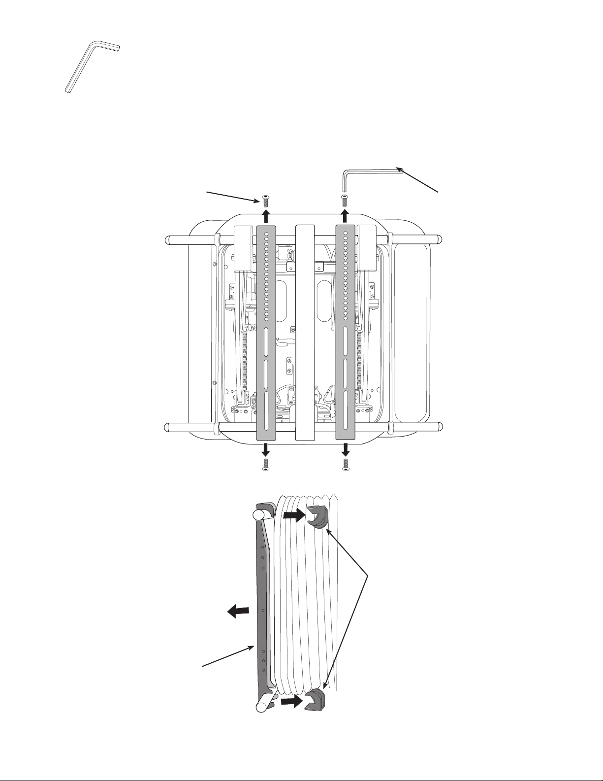
2: Remove Mounting Brackets
P1
P
R
E
S
E
T
MENU
P2
P1
P3
TV
SET
X-ARM
VCR
DVD
CBL
SEL
IN/OUT
P
R
E
S
E
T
MENU
EXIT
P2
P4
[27]
You must remove the two TV Mounting Brackets from the LA112 before attaching the arm to the wall plate.
Remove the hex screws [A] from the mounting brackets [03]. Pull the safety clips [04] from the back of the mounting brackets,
then remove the mounting brackets from the arm assembly.
[A]
[27]
[03]
[04]
6901-100189 <01>
Page 7
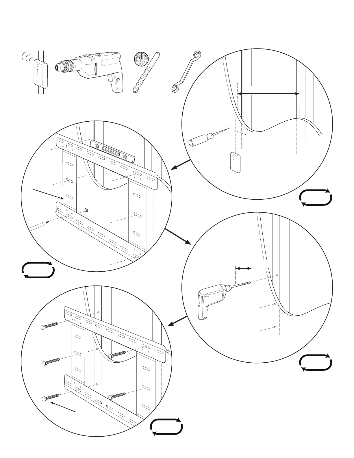
3: Mount Wall Plate
For Wood Stud Walls
[01]
1/8 in.
Max. 43 cm (17 in.)
2x
6x
6901-100189 <01>
Min. 6.5 cm (2.5 in.)
6x
[10]
6x
Page 8
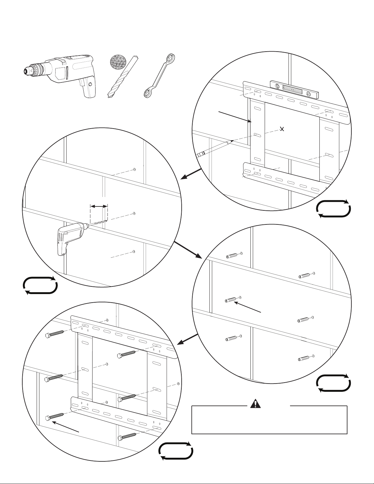
Min. 6.5 cm (2.5 in.)
For Concrete Block or Brick Walls
1/2 in.
[01]
6x
6x
[11]
6x
CAUTION
Avoid potential injuries and / or property damage!
Never drill into the mortar between concrete blocks!
[10]
6x
6901-100189 <01>
Page 9
4: Install Arm Assembly to Wall Plate
[02]
Hang the arm assembly [02] over the top rail of the wall plate
[01]. Be sure both hooks on the arm assembly engage with the
rail.
Align the arm assembly to the desired location on the wall
plates. Secure the bottom of the arm assembly to the wall
plate by tightening the two fasteners [A] at the bottom of
the arm assembly.
[01]
6901-100189 <01>
[A]
Page 10
5: Set the Monitor Width
Set
Selector
Set
CAUTION
Avoid potential injuries and / or property damage! Do
not use the monitor manufacturer’s “screen size”; you
must measure the width of the monitor case, including
any speakers attached to the sides.
CAUTION
The LA112 restricts movement based up on the TV
widteh set on the side controls. The TV widthe must be
set correctly before operating the LA112.
To set the monitor width, determine the correct code from
the chart below.
Insert the power cord [08] into the plug on the arm assembly,
then connect the power cord to a grounded outlet.
Turn the power switch [A] to the ON position. Insert the
selector pin [07] into the receptacle [B] and press until the
correct code is displayed.
Press and hold the “Set” button [C] until the display stops
blinking to accept the code.
Measure monitor width,
including any speakers
[A]
CODE WIDTH
C1 102 - 113 cm (40 - 44.9 in.)
C2 114 - 123 cm (45 - 48.9 in.)
C3 124 - 140 cm (49 - 55.9 in.)
C4 141 - 155 cm (56 - 61.0 in.)
[B]
[C]
[07]
[08]
6901-100189 <01>
Page 11

6: Install Mounting Brackets
P1
P3
TV
SET
X-ARM
VCR
DVD
CBL
SEL
IN/OUT
P
R
E
S
E
T
MENU
EXIT
P2
P4
CAUTION
If your television came with mounting bolts use those. If
not, select bolts from those supplied with your LA112. Bolts
selected must match the manufacturer’s recommendations.
Top
Circular holes and hook
[03]
[18, 19, 20]
[21, 22, 23]
[12, 13, 14,
15, 16, 17]
6.1
Connect the IR receiver cable [06] to the receiver port on the arm assembly.
On the remote control [09], press the “X-ARM” button to activate the remote. Then press the “SEL-IN/OUT” button once to
extend the arm.
[06]
6901-100189 <01>
Page 12

[A]
AV Cables
to TV
AV Cables from
Component
TV Power Outlet
(outside bellows)
Power
to TV
IR Reciever Eye
IR Reciever
Plug
Cable Loops
Bellows
No Cable
2” (5 cm)
No Cable
2” (5cm)
Cable Bar
Bottom Cross Bar
Cable Hole
Cable Tie Anchor
7: Route Cables
For Power Outlets Located Outside the Bellows
[B]
[C]
[26]
[07]
CAUTION
Avoid potential property damage! Keep all cables away
from the center beam of the arm assembly. Do not place
Route the AV cables [A] over the bottom cross bar, through one of the cable loops [B], then through the
cable access port at the back of the arm assembly. Route the power cord [07] over the bottom cross bar,
through the opposite cable loop [B], then through the cable access port at the bottom of the arm assembly.
Disconnect the plug end of the IR receiver cable [06] and route the cable over the bottom cross bar, through
one of the cable loops [B], then through the access port at thebottom of the arm assembly.
Secure the cables to the bottom cross bar with cable ties [26] as shown. Be sure to keep all cables at least
5cm (2 in.) away from the center beam!
Check that the cables are long enough to allow free movement of the arm assembly, but are not long
enough to get caught in the mechanical parts of the arm assembly. Using the remote, adjust the arm up,
down, and side to side through its full extension. Secure the cables to the cable bar [C] at the back of the
arm assembly.
cables closer than 5cm (2 in.) on either side of the beam.
[06]
6901-100189 <01>
Page 13

[C]
AV Cables
to TV
AV Cables from
Component
TV Power
Cord
AV Cable Loop
Bellows
No Cable
2” (5 cm)
No Cable
2” (5 cm)
Cable Bar
Cable Hole
Bottom Cross Bar
IR Receiver Eye
TV Power outlet
inside belows.
Cable Tie Anchor
TV Power &
IR Receiver Hook
For Power Outlets Located Inside the Bellows
CAUTION
Avoid potential property damage! Keep all cables away
from the center beam of the arm assembly. Do not place
cables closer than 5cm (2 in.) on either side of the beam.
[B]
[A]
[06]
6901-100189 <01>
[08]
Route the AV cables over the bottom cross bar, through the left cable loop [A], then through the cable
access port at the bottom of the arm assembly.
Route the power cord [08] over the bottom cross bar, through the opposite cable loop [B], then through the
cable access port at the bottom of the arm assembly. Disconnect the plug end of the IR receiver cable [06]
and route the cable over the bottom cross bar, through the right cable loop [B], then through the access
port at the back of the arm assembly.
Secure the cables to the bottom cross bar with cable ties [26] as shown. Be sure to keep all cables at least
5cm (2 in.) away from the center beam!
Check that the cables are long enough to allow free movement of the arm assembly, but are not long
enough to get caught in the mechanical parts of the arm assembly. Using the remote, adjust the arm up,
down, and side to side through its full extension. Secure the cables to the cable bar [C] at the back of the
arm assembly.
Page 14

8: Install Monitor to Wall Plate
[27]
Position the hooks at the top of the mounting
brackets over the top cross bar [A].
Guide the bottom of the mounting brackets down
and towards the arm assembly until the brackets
engage with the bottom cross bar.
Install the four safety clips [04] as shown. Secure the
safety clips with the fasteners [B].
HEAVY! You will need assistance
with this step.
[A]
[04]
[B]
[B]
6901-100189 <01>
Page 15

9: Calibrate the Arm
Calibrate Arm to the Monitor
NOTE: LA112 must be calibrated to the TV to avoid hitting the wall.
1. Turn the control box power switch to “Off”.
2. While holding down the “Set” button, turn the control box power switch back on and continue to hold Set until “Ct” appears in
the LED display.
3. Stand away from the LA112 as it calibrates. LA112 will move back to the home position against the wall when calibration is
complete.
4. If your TV is not parallel with the wall, proceed to the next section, “Reset the LA112 to Home Position”.
Reset the LA112 Home Position
1. Move the X-arm to its home position against the wall by pressing the “SEL-IN/OUT” button on the remote control.
2. Insert the pointer into the control box Selector hole and press the “SET” button until the display reads “HP”.
3. Adjust the X-arm to the desired home position using the arrow keys on the remote control.
4. Press and hold the control box “Set” button for three seconds. Now the X-arm will move to the new home position each time
the “SEL-IN/OUT” button on the remote control is pushed.
Adjust Monitor Position
CAUTION
Avoid property damage and personal injury. Set the correct width for your TV before using the LA112. See the “Setting
LA112 TV Width” section above to set the correct width for your TV. While the LA112 is in motion keep people and objects
away from it and do not leave it unattended.
1. Turn the control box power switch to “On”.
2. Press the “X-arm” and the the “Power” keys on the remote control.
3. If the TV width code is not displayed on the control box, press “POWER” on the remote. Then press “SEL-IN/OUT” once to
extend the TV out from the wall. There is no need to hold down the button. Pressing any of the arrow buttons while LA112 is
moving the TV will stop it.
4. Use the remote control arrow keys to move the TV in the desired direction. To stop movement, press any of the arrow keys or
the “SEL-IN/OUT” key.
6901-100189 <01>
Page 16

Select the desired device.
Remote Control
P1
P3
VOL
+
CH
TV
SET
X-ARM
VCR
DVD
CBL
SEL
IN/OUT
P
R
E
S
E
T
MENU
EXIT
MUTE
FAV
1 2 3
4 5 6
7 8 9
0
P2
P4
+
P1
P3
VOL
+
CH
POWER
TV
SET
X-ARM
VCR
DVD
CBL
SEL
IN/OUT
P
R
E
S
E
T
P
R
E
S
E
T
MENU
EXIT
MUTE
FAV
1 2 3
4 5 6
7 8 9
0
P2
P4
+
PIP SWAP
OPEN/CLOSE
POSITION
FREEZE SLEEP
INFO
TV/VCR GUIDE
LAST
ENTER
X-ARM
P3
VOL
+
CH
POWER
TV
SET
X-ARM
VCR
DVD
CBL
SEL
IN/OUT
P
R
E
S
E
T
EXIT
MUTE
FAV
P4
+
P3
+
X-ARM
VCR
DVD
CBL
SEL
IN/OUT
P
R
E
S
E
T
EXIT
MUTE
P4
P1
P3
TV
SET
X-ARM
VCR
DVD
CBL
SEL
IN/OUT
P
R
E
S
E
T
P2
P4
P3
VOL
+
CH
POWER
TV
SET
X-ARM
VCR
DVD
CBL
SEL
IN/OUT
P
R
E
S
E
T
EXIT
MUTE
FAV
P4
+
INFO
TV/VCR GUIDE
P1
P3
VOL
+
CH
TV
SET
X-ARM
VCR
DVD
CBL
SEL
IN/OUT
P
R
E
S
E
T
MENU
EXIT
MUTE
FAV
1 2 3
4 5 6
7 8 9
0
P2
P4
+
P3
VOL
+
CH
POWER
TV
SET
X-ARM
VCR
DVD
CBL
SEL
IN/OUT
P
R
E
S
E
T
EXIT
MUTE
FAV
1 2 3
4 5 6
7 8 9
0
P4
+
INFO
TV/VCR GUIDE
LAST
ENTER
Remote Control
P1
P3
VOL
+
CH
TV
SET
X-ARM
VCR
DVD
CBL
SEL
IN/OUT
P
R
E
S
E
T
MENU
EXIT
MUTE
FAV
1 2 3
4 5 6
7 8 9
0
P2
P4
+
P3
VOL
+
CH
POWER
TV
SET
X-ARM
VCR
DVD
CBL
SEL
IN/OUT
P
R
E
S
E
T
MENU
EXIT
MUTE
FAV
1 2 3
4 5 6
7 8 9
0
P4
+
INFO
TV/VCR GUIDE
LAST
ENTER
Remote Control
P1
P3
VOL
+
CH
TV
SET
X-ARM
VCR
DVD
CBL
SEL
IN/OUT
P
R
E
S
E
T
MENU
EXIT
MUTE
FAV
1 2 3
4 5 6
7 8 9
0
P2
P4
+
P3
VOL
+
CH
POWER
TV
SET
X-ARM
VCR
DVD
CBL
SEL
IN/OUT
P
R
E
S
E
T
EXIT
MUTE
FAV
1 2 3
4 5 6
7 8 9
0
P4
+
PIP SWAP
OPEN/CLOSE
INFO
TV/VCR GUIDE
LAST
ENTER
Remote Control
P1
P3
VOL
+
CH
TV
SET
X-ARM
VCR
DVD
CBL
SEL
IN/OUT
P
R
E
S
E
T
MENU
EXIT
MUTE
FAV
1 2 3
4 5 6
7 8 9
0
P2
P4
+
P3
VOL
+
CH
POWER
TV
SET
X-ARM
VCR
DVD
CBL
SEL
IN/OUT
P
R
E
S
E
T
EXIT
MUTE
FAV
1 2 3
4 5 6
7 8 9
0
P4
+
PIP SWAP
OPEN/CLOSE
POSITION
FREEZE SLEEP
INFO
TV/VCR GUIDE
LAST
ENTER
Remote Control
P1
P3
VOL
+
CH
TV
SET
X-ARM
VCR
DVD
CBL
SEL
IN/OUT
P
R
E
S
E
T
MENU
EXIT
MUTE
FAV
1 2 3
4 5 6
7 8 9
0
P2
P4
+
P3
+
CH
X-ARM
VCR
DVD
CBL
SEL
IN/OUT
P
R
E
S
E
T
EXIT
MUTE
FAV
0
P4
OPEN/CLOSE
TV/VCR GUIDE
ENTER
P3
X-ARM
VCR
DVD
CBL
SEL
IN/OUT
P
R
E
S
E
P3
P
R
E
S
E
T
EXIT
P4
X-ARM
P3
+
CH
X-ARM
CBL
P
R
E
S
E
T
EXIT
P4
X-ARM
P3
+
CH
X-ARM
VCR
DVD
CBL
SEL
P
R
E
S
E
T
EXIT
MUTE
FAV
P4
P1
P3
TV
SET
X-ARM
VCR
DVD
CBL
SEL
IN/OUT
P
R
E
S
E
T
P2
P4
P3
+
CH
X-ARM
VCR
DVD
CBL
SEL
IN/OUT
P
R
E
S
E
T
EXIT
MUTE
FAV
P4
TV/VCR GUIDE
P1
P3
TV
SET
X-ARM
VCR
DVD
CBL
SEL
IN/OUT
P
R
E
S
E
T
P2
P4
P3
+
CH
X-ARM
CBL
P
R
E
S
E
T
EXIT
P4
Remote Control
P1
P3
VOL
+
CH
TV
SET
X-ARM
VCR
DVD
CBL
SEL
IN/OUT
P
R
E
S
E
T
MENU
EXIT
MUTE
FAV
1 2 3
4 5 6
7 8 9
0
P2
P4
+
P3
+
CH
X-ARM
CBL
P
R
E
S
E
T
EXIT
P4
OPEN/CLOSE
ENTER
Remote Control
P1
P3
VOL
+
CH
TV
SET
X-ARM
VCR
DVD
CBL
SEL
IN/OUT
P
R
E
S
E
T
MENU
EXIT
MUTE
FAV
1 2 3
4 5 6
7 8 9
0
P2
P4
+
P3
+
CH
X-ARM
VCR
DVD
CBL
SEL
IN/OUT
P
R
E
S
E
T
EXIT
MUTE
FAV
0
P4
OPEN/CLOSE
FREEZE SLEEP
TV/VCR GUIDE
ENTER
Remote Control
P1
P3
VOL
+
CH
TV
SET
X-ARM
VCR
DVD
CBL
SEL
IN/OUT
P
R
E
S
E
T
MENU
EXIT
MUTE
FAV
1 2 3
4 5 6
7 8 9
0
P2
P4
+
P3
+
CH
X-ARM
CBL
P
R
E
S
E
T
EXIT
P4
OPEN/CLOSE
ENTER
Sets the P1 or P2 Preset position to the
current X-Arm position.
Moves LA112 to the selected preset
position.
In X-arm mode: Tilt the TV.
In TV, DVD and CBS modes: Navigate
on-screen menu of selected device.
Opens the setup menu for the selected
device.
Adjusts the volume up or down.
Turns the sound off for the selected
device.
Displays information about the current
video source.
Returns to the previous channel.
Rewind, play, fast-forward, pause, stop,
and record functions for videos.
TV
VCR
DVD
SET
p
p1
r
e
s
e
t
p2
menu
CBL
p3
p4
X-ARM
p
r
e
s
e
t
Remote Control
In TV mode: Freezes PIP.
In DVD mode: Displays Setup menus.
In VCR mode: Displays tape speed.
In CBL mode: Page Up.
Puts the selected device into a low power
consumption state.
10. Using the
Turns on the Picture in Picture feature.
In CBL mode: Moves the page down.
In PIP mode: Changes the position of
the PIP window.
Switches the PIP and background
video sources.
In X-arm mode: Returns LA112 to
home position.
In TV, DVD and CBL modes: Selects or
sets options.
Leaves the current menu.
Changes to the next or previous
channel or chapter.
In CBL mode: Returns to programmed
favorite channels.
Rotates through the available video
sources for the selected device.
In CBL mode: Displays guide.
In TV mode: Opens closed captioning
(CC).
Opens/closes the media tray for the
selected device.
6901-100189 <01>
Page 17

Programming the Preset Position Keys
X-ARM
P1
P3
VOL
+
CH
POWER
TV
SET
X-ARM
VCR
DVD
CBL
SEL
IN/OUT
P
R
E
S
E
T
P
R
E
S
E
T
MENU
EXIT
MUTE
FAV
P2
P4
+
X-ARM
POWER
X-ARM
POWER
TV
SET
X-ARM
VCR
DVD
CBL
CAUTION
To avoid injury or property damage, confirm correct TV width is set before programming the Perset Positions. Do not
come in contact with the LA112 while it is in motion.
1. Turn control box power switch to “On”.
2. Press +
3. Move the LA112 to the desired position for preset using the remote control
arrow keys.
4. Press
5. Select the desired preset button twice within 3 seconds to set.
6. Repeat steps 1-5 for the remaining presets.
6901-100189 <01>
Page 18

X-ARM
P1
P3
VOL
+
CH
POWER
TV
SET
X-ARM
VCR
DVD
CBL
SEL
IN/OUT
P
R
E
S
E
T
P
R
E
S
E
T
MENU
EXIT
MUTE
FAV
P2
P4
+
POWER
TV
X-ARM
VCR
DVD
CBL
P3
X-ARM
VCR
DVD
CBL
SEL
IN/OUT
P
R
E
S
E
Programming the Remote to Operate an Existing TV
P3
X-ARM
VCR
DVD
CBL
SEL
IN/OUT
P
R
E
S
E
1. Turn your TV on.
2. Find your TV’s codes from the list on the following page.
3. Press and hold until the TV button stays lit.
+
4. Point the remote at your TV and enter a code from the list. Keep entering codes until
the TV powers off.
5. Press The TV button will blink 3 times and go out.
6. Test that the remote works properly with your TV. If not, repeat steps 3-5.
NOTE: To program the remote control to operate your DVD player, VCR and cable box, follow the above steps replacing “TV” for
the appropriate device. The following pages list TV, DVD player, VCR and cable box codes.
6901-100189 <01>
Page 19

TV Brand Code Numbers TV Brand Code Numbers
Admiral 220 160 081 072 Emerson 245 155 154 143 096 076 051 048
047 043 028 005 004 001
Advent 231 Fisher 057 007
Aiwa 213 Fujitsu 244
Akai 146 001 Funai 245 043 028
Amark 143 Funai 245 043 028
Ampro 073 Futuretech 043
Amstrad 052 Gateway 041 202
Anam 242 131 080 056 043 GE 220 165 160 155 144 074 073 056
034 009 008 004 001
Aoc 058 004 001 Gradiente 218
Apex 247 haier 203
Audiovox 076 Hallmark 004
Blaupunkt 088 HitachiI 143 075 072 023 012 011 010 009
004
Broksonic 241 Infinity 249 164
Caim 201 JBL 249 164
Candel 004 003 002 001 JCPenney 160 143 101 065 030 024 009 008
004 001
Capehart 058 Jensen 013
Cetronic 043 JV 237 230 145 083 070 038 034
Citizen 143 103 101 043 004 003 002 001 KEC 043
Classic 043 Kenwood 070 001
Concerto 004 Kloss 059 002
Contec 051 043 KMC 143
Cornea System 246 KTV 250 154 143 043 001
Coronado 143 LG (Goldstar) 143 127 119 106 004
Craig 043 Lodgenet 072
Crown 143 043 Loewe 249
Curtis Mathes 143 101 004 001 Logik 072
CXC 043 LXI 249 164 160 081 052 015 007
Daewoo 143 127 125 114 103 076 043 027
016 004
Magnovox 249 205 223 222 216 210 164 160
127 094 064 063 060 059 022 004
003 001 218 219
Daytron 143 004 Marantz 249 164 001
Dell 036 Matsui 164
Dwin 177 Memorex 096 072 007 004
Dynasty 043 Metz 088
Dynatech 062 Mga 042 028 024 004 001
Eiki 187 Minerva 088
Electrohome 196 143 076 024 Mitsibushi 225 146 124 109 042 040 031 028
021 024 004
Motorola 217 Signature 072
MTC 101 062 004 001 Sony 194 147 139 070
Programming Codes
TV Programming Codes
6901-100189 <01>
Page 20

Programming Codes
TV Brand Code Numbers TV Brand Code Numbers
Nad 025 015 Soundesign 043 028 004 003
NEC 056 040 024 019 016 001 SSS 043 004
Nikei 043 Supremacy 002
Olevia 045 Sylvania 249 245 240 229 226 211 164 160
127 064 063 060 059 003
Onking 043 Symphonic 245
Omwa 043 Tandy 081
Optonica 081 019 Signature 072
Orion 096 Tatung 062 056
Panasonic 250 249 238 227 164 080 056 034 Technics 080 034
Philco 164 064 063 060 059 056 024 004
003 0011
Techwood 004
Phillips 249 205 164 127 093 059 038 005
004 003 001
Teknika 043 101 072 043 028 024 004 003
002
Pioneer 135 025 023 018 001 Telefunken 037
Portland 143 004 Telerent 072
Proscan 197 165 220 160 144 Tera 172
Proton 173 171 143 131 058 004 Thomas 245
Quasar 250 056 044 034 017 TMK 004
Radio Shack 143 127 043 019 004 Toshiba 232 138 101 062 040 032 030 015
007
RCA 228 220 165 160 152 144 074 065
056 024 023 004 001
Totevision 143
Realistic 047 043 019 007 Universal 009 008
Roctec 186 Viceo Concepts 146
Runco 182 168 073 Vidikron 184
Sampo 202 058 004 001 Vidtech 004
Samsung 251 248 209 160 143 127 105 101
089 026 004
Visio 100
Sanyo 082 057 053 020 007 Wards 249 164 143 074 072 064 063 060
034 028 019 009 008 004
Sceptre 035 Westinghouse 245 076
Scott 143 048 043 028 004 Yamaha 004 001
Sears 165 160 143 094 082 057 030 028
015 007 004
York 004
Sharp 207 170 143 081 029 028 022 Yupiteru 043
Siemens 088 Zenith 103 095 073 072
TV Programming Codes, continued
6901-100189 <01>
Page 21

DVD Brand Code Numbers DVD Brand Code Numbers
Apex Digital 153 220 Nad 221
Broksonic 017 Onkyo 233 001
Cyberhome 165 020 004 Panasonic 234 228 167 152 149
Daewoo 193 171 Phillips 237 166 168 016 007
Denon 240 226 Pioneer 230 229 189 015
Emerson 158 150 148 Proceed 219
GE 243 231 Proscan 231 229
Go Video 014 160 002 RCA 243 231 170 019
Bgradiente 201 192 Samsung 248 161 013 005
Harmon Kardon 225 218 173 Sansui 017
Humax 190 191 Sanyo 006
JVC 238 012 Sharp 222 202
Kenwood 224 Sony 244 232 204 169 003 009
KLH 223 Sylvania 172 150
LG (Goldstar 249 247 241 235 Thompson 243 231
Lite On 021 TIVO 191
Magnavox 237 163 168 016 Toshiba 250 245 233 190 194 151 011 018
Marantz 168 Yamaha 246 234
Memorex 008 Zenith 247 241 235 014
Mitsubishi 227
Programming Codes
DVD Programming Codes
6901-100189 <01>
Page 22

Programming Codes
VCR Brand Code Numbers VCR Brand Code Numbers
Aiwa 461 334 Magin 404
Akai 446 425 424 346 343 316 Magnavox 464 456 445 367 334
Ampro 372 Marantz 445 369 367 312
Anam 445 Marts 406
Audio Dynamics 343 339 312 Matsui 330
Bloksonic 429 337 Mei 445
Canon 445 Memorex 445 439 406 372 353 334 314
310 301
Capehart 408 MGA 359 346
Craig 435 404 301 Minolta 501
Curtis Mathes 445 341 MTC 404 334
Daewoo 417 412 411 408 310 307 305 Multitech 334 324
Daytron 408 343 339 312 NEC 4348 343 339 312
DBX 353 339 312 Nordmende 343
Dynatech 353 334 Optonica 353
Electrohome 359 Orion 325
Emerson 467 431 429 417 406 445 346
337 336 334 325 306
Panasonic 511 502 445 374 370
Fisher 310 309 308 301 Pentax 445 320
Funia 334 Philco 445 367 334
GE 447 444 409 407 445 372 Philips 406 445
Go Video 468 455 436 432 404 Pilot 406
Harman Kardon 346 312 Pioneer 348 321 320
Hitachi 460 343 334 326 320 Portland 408
Instant Replay 445 Proscan 505 504
JCL 445 Pulsar 372
JCPenney 406 404 445 320 Quartz 341 302
Jensen 343 Quasar 445
JVC 452 430 445 360 348 312 Radio Shack 423
Kenwood 348 347 334 314 RCA 509 458 447 445 444 409 407
404 341 334 320
LG (Goldstar) 423 414 406 320 312 Realistic 406 404 445 353 334 314 310
308 301
Lloyd 334 RICO 358
LXI 406 334 309 301 Runco 448
VCR Programming Codes
6901-100189 <01>
Page 23

Programming Codes
VCR Brand Code Numbers VCR Brand Code Numbers
Salora 314 TEAC 343 339 334
Samsung 508 468 425 412 409 407 404
445 332
Technics 445 370
Sansui 435 348 343 Teknika 406 445 334 319
Santo 404 314 310 307 301 Thomas 334
Scott 431 429 412 337 TMK 306
Sears 412 406 320 314 310 309 308
301
Toshiba 521 431 413 412 382 359 347
320 308
Sharp 515 465 459 445 353 Totevision 406 404
Shintom 324 Unitech 404
Signature 334 Vector Research 312
Sony 512 506 454 453 445 378 376
358 357 356 353 352 301
Victor 348
Soundesign 034 Video Concepts 346 334 312
STS 320 Videosonic 404
Sylvania 520 519 518 445 367 359 334 Wards 431 404 445 353 324 320 301
Symphonic 334 Yamaha 343 339 334 312
Tandy 334 310 Zenith 467 406 380 732 358 356 348
334
Tatung 343 339
VCR Programming Codes, continued
6901-100189 <01>
Page 24

Brand Code Numbers Brand Code Numbers
ABC 205 200 103 039 004 Novaplex 092
Amricast 099 NSC 038
Antronit 014 Oak 204 037
Archer 014 007 Panasonic 047 044
Bell South 099 Paragon 008
Centurion 092 Philips 095 085 020 017
Century 007 Pioneer 203 231 121 105 034 103
Citizen 007 Prucer 078 047
Combano 081 080 PTS 202 001
consat 001 Pulsar 008
Comtronics 030 RCA 047
Digicable 206 Reconton 098
Eagle 003 030 020 Regal 049
Eastern 066 057 Regency 057
Echostar 106 Samsung 030
Electricord 032 Scientific Atlanta 231 205 200 118 117 110 042 037
034 011 008 001
Gemini 201 054 Signal 030
General Electric 072 Signature 103
General 104 001 103 SL Marx 030
GNC 099 Sony 214 213 212 211
Golden 030 Starcom 231 201 004
Hamlin 049 Stargate 201 104 030
Hitachi 103 Tadiran 030
Jerrold 231 201 200 101 069 004 001 103 Time Warner 231
Magnavox 095 094 Tocom 056 039 003
Media One 017 Toshiba 008
Memorex 008 Unika 014 007
Mitsubishi 102 United Cable 004
M-Net 204 Universal 035 032 014 007
Motorola 001 001 Viewstar 089 087 086 020 018
Movie Time 032 Zenith 093 060 008
Programming Codes
For Cable Boxes
6901-100189 <01>
Page 25

11: Troubleshooting
Power Switch
Control Box
LED Display
Selector
Set Button
motor
motor
motor
A1 A2 A3
control box wires
switch switch
switch
X-arm™ Will Not Move
If X-arm becomes unresponsive, first check to see what the LED display on the
side of the X-arm control reads. Then choose a course of action based upon
the code.
“A1”, “A2”, or “A3” is displayed on control box
Possible Causes:
One of the motor cables is disconnected.
•
One of the “stop” sensors is disconnected, misaligned or broken.
•
One of the long drive screws is dirty.
•
A motor coupling is loose.
•
How to Correct:
1. Unplug X-arm™ from power for at least 10 seconds.
2. Check that the TV and X-arm™ are not trapped against the wall or any other object.
3. Plug in X-arm™, turn on the power and try to move the X-arm™ using the remote
control. If it works properly, do not continue to step 4.
4. With the X-arm™ powered on, insert the provided plastic pointer in the Selector
hole on the side of the X-arm™ and press it until “t” shows on the LED display.
5. Using the remote control, straighten X-arm™ so that it is parallel with the wall, and
then press the “Set” button on the control box for three seconds. The X-arm™ should
return to the home position against the wall.
6. Unplug X-arm™ from power for at least 10 seconds and then plug it in again. Turn
on the power and try to move the X-arm™ using the remote control. Continue to the
next step if it does not work correctly.
7. Unplug the X-arm™ from power.
8. Remove the TV and inspect the areas in the picture corresponding to the error
message. For example, if A3 is displayed on the LED, look at areas in the A3 box. Make
sure that all motor and “stop” switch wire connections are securely connected.
9. Check to see that the wires leading to the control box are securely connected.
10. Clean an substances or particles from the long drive screws.
11. Plug in X-arm™, turn on the power and try to move the X-arm™ using the remote
control.
6901-100189 <01>
Page 26

Troubleshooting
Power Switch
Control Box
LED Display
Selector
Set Button
continued
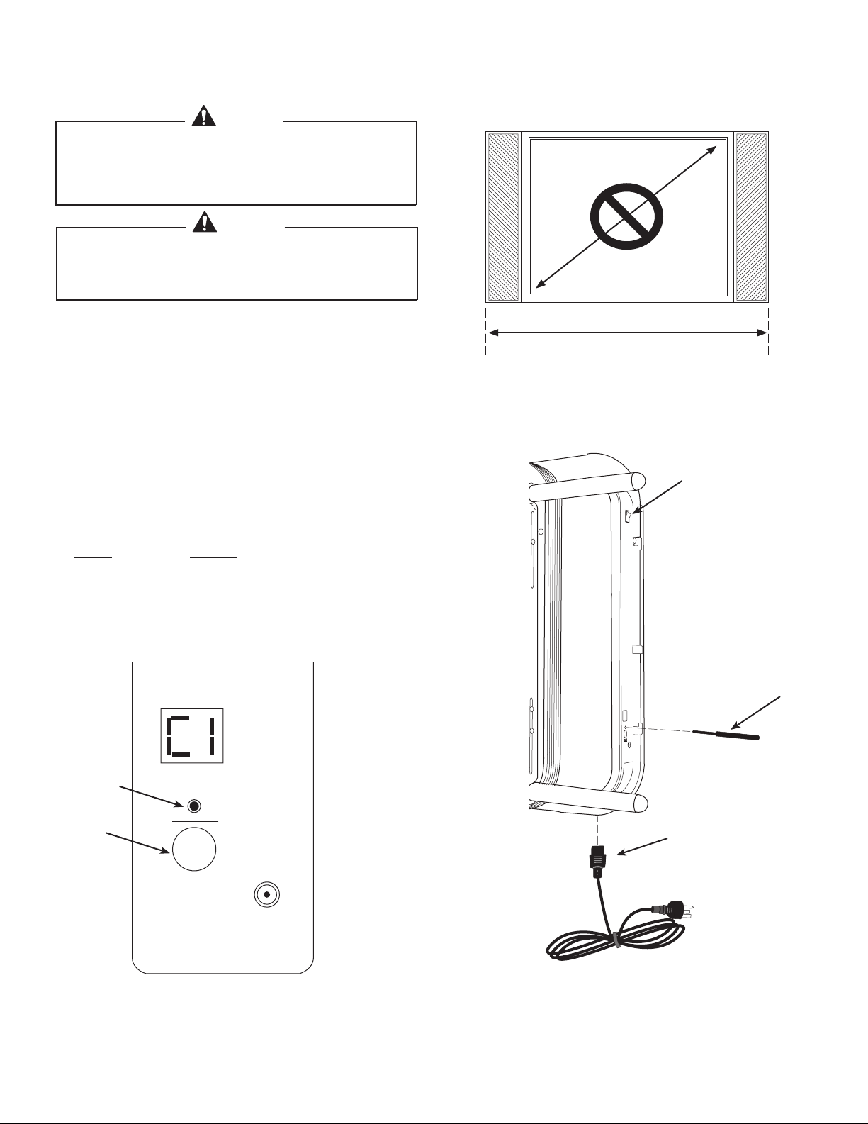
“C1”, “C2”, “C3” or “C4” is displayed on control box
Normally X-arm™ will show the code associated with the TV mounted on it.
1. Check that the IR receiver is plugged into the side of the X-arm™ and that the IR Receiver eye is in direct line of
sight with the remote control.
2. Make sure that the code set on the control box is the correct code for the TV width mounted.
Code TV Outside Width
C1 40” - 44.9” (102 - 113 cm)
C2 45” - 48.9” (114 - 123 cm)
C3 49” - 55.9” (124 - 140 cm)
C4 56” - 63.0” (142 - 160 cm)
If the code is incorrect, reset the width code.
2-1. Press the power switch to ON (1).
2-2. Measure the total outside width of the TV including any side speakers that may be attached to the TV. Do
not use the TV manufacturer’s screen size, which is measured diagonally, to set the TV width on X-arm™.
2-3. Insert the provided plastic pointer into the selector hole, and press the button until the TV width code
corresponds to the outside width of your TV as indicated in the table below.
Code TV Outside Width
C1 40” - 44.9” (102 - 113 cm)
C2 45” - 48.9” (114 - 123 cm)
C3 49” - 55.9” (124 - 140 cm)
C4 56” - 63.0” (142 - 160 cm)
2-4. Hold the black rubber set button, below the selector hole, until the TV width code stops blinking.
3. Check that the TV and X-arm™ are not trapped against the wall or any other object.
4. Plug in X-arm™, turn on the power and try to move the X-arm™ using the remote control. If it works properly,
do not continue to the next step.
5. Insert the provided plastic pointer into the Selector hole on the side of X-arm™, and press the button until a “t”
is shown.
6. Using the remote control, straighten X-arm™ so that it is parallel with the wall and then press the Set button
on the control box for three seconds. X-arm™ will return to the home position.
7. Unplug X-arm™ and plug it in again.
6901-100189 <01>
Page 27

Power Switch
Control Box
LED Display
Selector
Set Button
motor
motor
motor
switch switch
switch
HC Error
Troubleshooting
continued
“HC” is displayed on control box
Possible Causes:
Person or object is obstructing the motion of the X-arm™.
•
One of the large drive screws has dirt or something on it.
•
The linkages are rubbing against something.
•
A motor cable has a short.
•
How to Correct:
1. Unplug X-arm™ from power for at least 10 seconds..
2. Check that the TV and X-arm™ are not trapped against the wall or any other
object.
3. Plug in X-arm™, turn on the power and try to move the X-arm™ using the
remote control. If it works properly, do not continue to the next step.
4. With the X-arm™ powered on, insert the provided plastic pointer in the
Selector hole on the side of the X-arm™ and press it until “t” shows on the LED
display.
5. Using the remote control, straighten X-arm™ so that it is parallel with the
wall, and then press the “Set” button on the control box for three seconds. The
X-arm™ should return to the home position against the wall.
6. Turn the power switch on the control box to “0” (OFF).
7. Hold down the Set button on the control box while switching the power
switch to “1” (ON). Continue holding down the Set button for 5 seconds until
the display reads CT.
8. Stand back while X-arm™ moves through the calibration sequence, moving in
and out, left and right and up and down.
9. X-arm™ is done calibrating when it goes back to the home position against
the wall.
10. Turn on the X-arm™ and test to see if it is operating normally. If it is not,
remove the TV from X-arm™ and continue.
11. Check that there are no foreign objects in the switches and motors in the
areas shown in the picture.
12. Check to see that the wire connections are securely connected and clean
any substances that are found around the large drive screws.
13. Check the motors for faults in the areas shown in the picture.
14. Plug in X-arm™. Turn on the power, and try to move X-arm™ using the
remote control.
6901-100189 <01>
Page 28

Troubleshooting
Power Switch
Control Box
LED Display
Selector
Set Button
H1
H2
H3
continued
“H1”, “H2”, or “H3” is displayed on control box
Possible Causes:
A cable has become disconnected.
•
A “stop” switch is faulty.
•
There is dirty or debris in one of the switches.
•
How to Correct:
1. Unplug X-arm™ from power.
2. Check that the TV and X-arm™ are not trapped against the wall or any other
object.
3. Plug in X-arm™, turn on the power and try to move the X-arm™ using the
remote control. If it works properly, do not continue to step 4.
4. Turn the power switch on the control box to “0” (OFF).
5. With the X-arm™ powered on, insert the provided plastic pointer in the Selector
hole on the side of the X-arm™ and press it until “t” shows on the LED display.
6. Using the remote control, straighten X-arm™ so that it is parallel with the wall,
and then press the “Set” button on the control box for three seconds. The X-arm™
should return to the home position against the wall.
7. Unplug X-arm™ from power for at least 10 seconds and then plug it in again.
Turn on the power and try to move the X-arm™ using the remote control.
Continue to step 8 if it does not work correctly.
8. Unplug the X-arm™ from power.
9. Remove the TV and inspect the areas in the picture corresponding to the
error message. For example, if H3 is displayed on the LED, look at areas in the H3
circle. Make sure that all motor and “stop” switch wire connections are securely
connected.
10. Clean and substances or particles from the long drive screws.
11. Plug in X-arm™, turn on the power and try to move the X-arm™ using the
remote control.
6901-100189 <01>
Page 29

Troubleshooting
continued
If Your TV Leans Forward at the Home Position
1. Move the LA112 to the home position against the wall by pressing the “SEL-IN/OUT” button on the remote once.
2. Insert the provided plastic pointer [07]into the control box Selector hole and press until the until the display reads “HP”.
3. Using the remote control arrow keys ( ) adjust the LA112 so that the TV is parellel with the wall.
4. Press the control box Set button for 3 seconds.
5. The LA112 will now go to the new home position you just programmed every time you select the SEL-IN/OUT
button.
12: Maintenance
Remove the TV from your LA112 yearly to check that no cords are interfering with moving parts.
6901-100189 <01>
Page 30

Home Automation Controls
RJ11/RS 232
Port
Cover Plate
Controlling X-arm™ with Home Automation (RJ11/RS232 port)
X-arm™ X700CS and X700CB (not available on the X700RS and X700RB) can be controlled through
Home Automation remote controls and control panels such as those made by Crestron, AMX, Control4
and life|ware. To do this, do the following:
1. Using a philips screw driver, remove both screws from the cover plate located at the bottom, right-hand side of
the control box.
2. Remove the cover plate to expose the RS232 port.
3. Download the RS232 program from the Home Automation vendor’s web site.
4. Plug the home automation control into the RS232 port on X-arm™ running the cord out the back hole in the
back plate of X-arm™.
5. Replace the cover plate and secure it in place with the screws.
6. Follow the vendor’s instructions.
CSAV, Inc. and its affiliated corporations and subsidiaries (collectively, “CSAV ”), intend to make this manual accurate and complete. However, CSAV makes no claim that the information
contained herein covers all details, conditions, or variations. Nor does it provide for every possible contingency in connection with the installation or use of this product. The information
contained in this document is subject to change without notice or obligation of any kind. CSAV makes no representation of warranty, expressed or implied, regarding the information
contained herein. CSAV assumes no responsibility for accuracy, completeness or sufficiency of the information contained in this document.
6901-100189 <01>
Page 31

Warranty
Sanus Systems and CLO warrants this product, under normal use, to be free from defects in material and workmanship for
a period of one year from the date of original purchase. Sanus Systems and CLO will, upon their discretion, repair or replace
such defective equipment within the warranty period free of charge provided that the products are returned prepaid to CLO.
Thereafter, repairs will be made at established factory prices. Unauthorized service or repair by anyone other than authorized
CLO personnel renders this Warranty void and releases Sanus Systems and CLO from any further responsibility or obligation.
LA112 mounting brackets are intended for use only with the maximum weight of 180 lbs (81 kg) and overall outside TV width
up to 63” (160 cm). Any damage caused by failure to observe proper packing or to observe instructions for installation or by
installing a TV over the specified maximim weight and/or maximim width prescribed, by accident or in transit or elsewhere
will not be covered by the Warranty. This Warranty is in lieu of all other Warranties expressed or implied, and no one is
authorized to assume any liability on behalf of Sanus Systems or CLO, or impose any obligation on Sanus Systems or CLO, in
connection with the sale of any product other than as outlined above. In no event will responsibility be assumed or implied
for consequential damage arising from the theft of any product secured by a CLO security device, by delay of installation,
interrupted operation or other causes.
For updates and information about the LA112, please visit our website at www.sanus.com.
Your sales receipt is rquired for this Warranty to be applicable.
In order to receive warranty service, your product must be registered within 30 days of purchase by mail. To register by mail, fill
out the Warranty Registration Card and mail it in with your original receipt.
To register by mail:
1. Fill out the Warranty Registration Card (below).
2. Provide a copy of your original sales receipt.
3. Mail both the card and the original sales receipt to the following address:
Warranty Registration
CLO Systems, LLC
1501 West Cameron Ave., Suite 215
West Covina, CA 91790
Cut here
Warranty Registration Card
Purchaser Information
First Name:
Last Name:
Address:
City:
Product Information
Model #
Serial #
Place of
Purchase:
Date of
Purchase:
mm/dd/yyyy
State:
Phone #:
E-mail:
6901-100189 <01>
 Loading...