

Page 1
Assembly Instructions for VMPR1
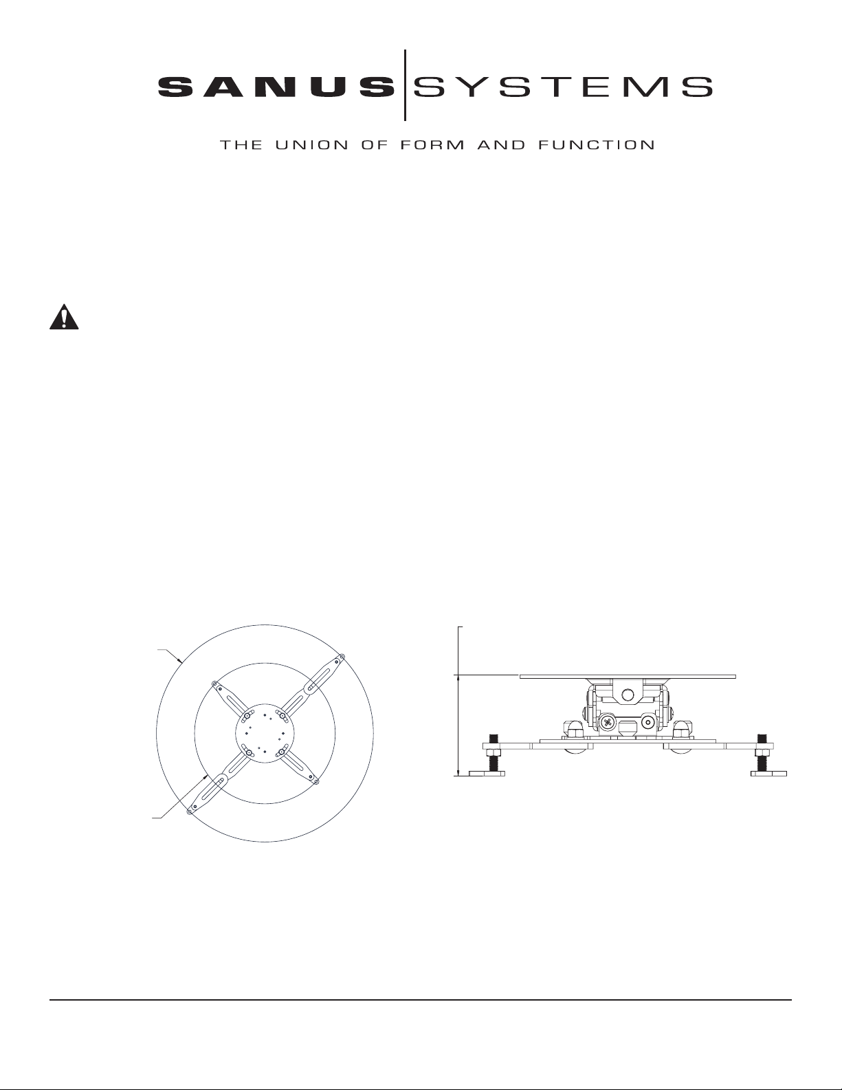
[469.884]
Ø18.50
[304.788]
Ø12.00
Covering area with
extension arms installed
Covering area without
extension arms installed
[62.160]
2.45
TO
[82.804]
3.26
Congratulations on your purchase! The VMPR1 ceiling mount provides a unique, simplified method of ceiling mounting inverted
LCD/DLP projectors. Its low profile design offers roll, pitch and yaw adjustment. The ceiling mount is a steel-to-steel construction with
adjustable height to maintain proper projector ventilation, holds registration for quick lamp changes and easy filter cleaning without
loosing registration.
Caution:
•The maximum weight to be installed on the mount is 50 pounds (22.68 Kg).
•To prevent damage to the mount, which could affect or void the Factory warranty, thoroughly study all instructions and illustrations
before you begin to install the VMPR1.
•If you have any questions about this installation, contact Sanus Systems at 800.359.5520
Warning: Improper installation can result in serious personal injury! Make sure that the structural
members can support a redundant weight factor five times the total weight of the equipment. If the structure can not support this weight, reinforce the structure before installing the VMPR1.
Required Tools: Open End Wrenches (M10 & M12). Phillips screwdrivers, No. 1 and No. 2. Allen Wrench (provided).
Note: Other tools may be required depending on the method of installation.
Dimensional Drawings:
Step 1: Inspect the Unit Before Installing
Carefully inspect the VMPR1 for shipping damage. Please call Sanus if anything is missing or damaged. Our customer service department can assist you quickly with any missing or damage parts. Never use damaged parts! Read all instructions before starting instal-
lation. Lay out components to ensure you have all the required parts before proceeding (see “PARTS” on the next page).
Sanus Systems 2221 Hwy 36 West Saint Paul MN 55113 10.27.04
800.359.5520 www.sanus.com
Page 2
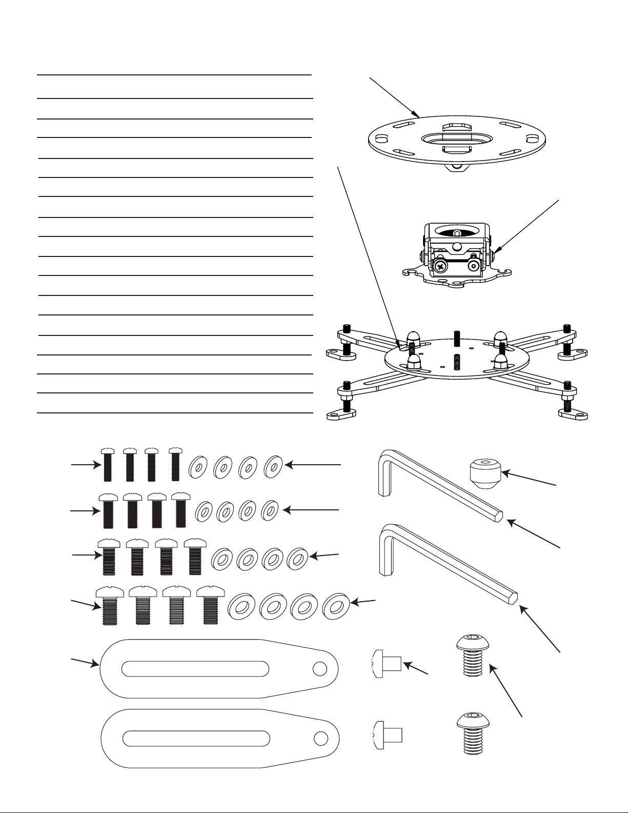
Parts: Check carefully to make sure all parts listed are not missing or damaged!
10
40
50
100 150
110 160
120 170 260
130 180
140 250
190
220
30
Item Nomenclature Qty.
10 Flush Mount Bracket 1
30 10-24 Thumb Nuts 4
40 Bottom VMPR1 Adjustable Projection Portion 1
50 Top VMPR1 Adjustable portion 1
100 M3 x 12mm Phillips Head Pan Screw 4
110 M4 x 12mm Phillips Head Pan Screw 4
120 M5 x 12mm Phillips Head Pan Screw 4
130 M6 x 12mm Phillips Head Pan Screw 4
140 Adjustable Extension Arm 2
150 M3 Flat Washer 4
160 M4 Flat Washer 4
170 M5 Flat Washer 4
180 M6 Flat Washer 4
190 M6 x 8mm Phillips Pan Screw 2
220 5/16-18 x 1/2” Button Head Cap Screw 2
250 Allen Key 1
260 Allen Key 1
Page 3
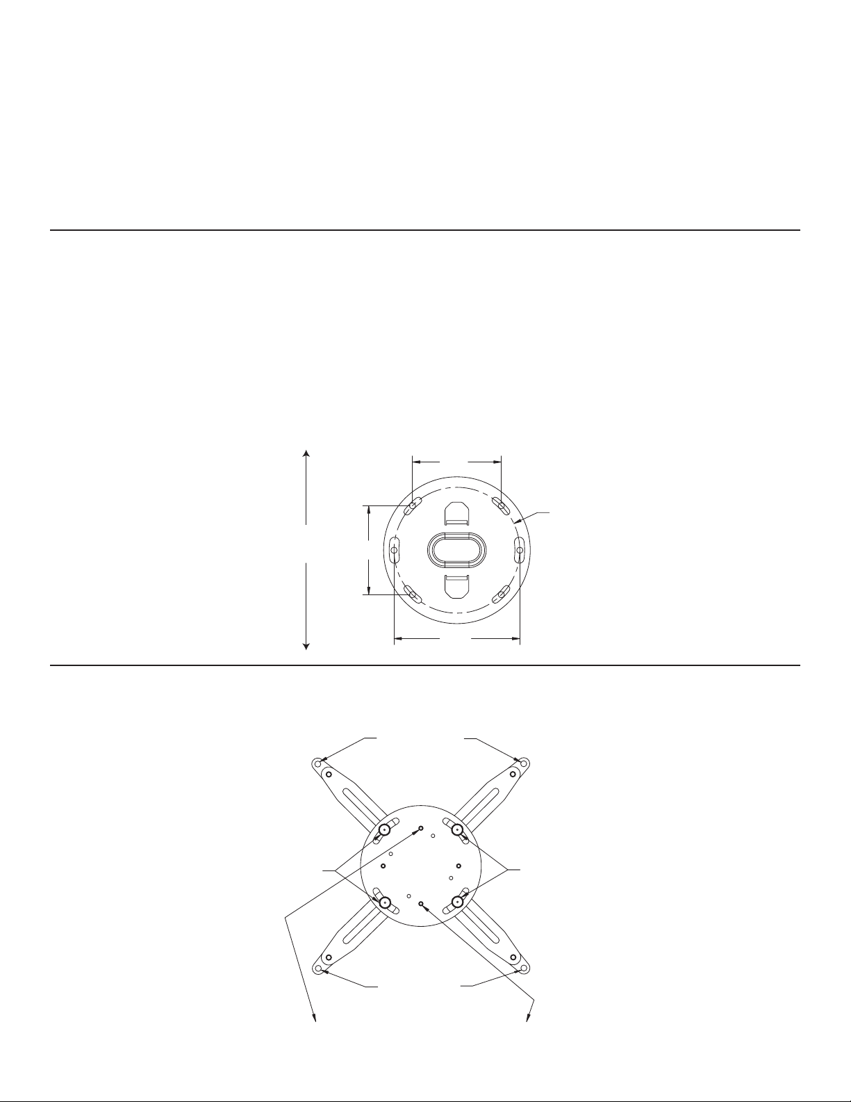
Step 2: Prepare the Ceiling
Back adjustable leg
mounting holes
Acorn hex nuts
Acorn hex nuts
Front adjustable leg
mounting holes
Install the mount bottom so one threaded stud is toward the front
and one toward the back of the projector
3.71
3.71
5.25
Ø
5.25
Plate should
face the screen
in this direction
Because of the wide variety of possible mounting situations, we can only provide general guidelines for installation. Study the following
information carefully, and adapt it as necessary to fit your specific installation. The “General Guidelines” below and the information on
the following pages cover the most common mounting situations:
General Guidelines:
• Carefully determine the position of the mount, and its distance from the screen. This will require knowing the lens to screen distance
(see projector specifications for set-up).
• Use the dimensions from the diagram below to drill hole locations in the ceiling.
The VMPR1 can be suspended from standard fasteners secured to a wood framing member.
WARNING: Improper installation can cause serious personal injury! Make sure the structural members can support a redundant weight factor five times the total weight of the equipment you intend to support overhead. If the structure cannot support
a redundant weight factor five times the total weight of the equipment, the structure must be reinforced before you install the
VMPR1.
Standard Fasteners Flush Mounting to a Wood Framing Member
The VMPR1 can be secured to a wood framing member through the two larger slots (5.25” apart) in the ceiling bracket using two 3/8”
lag screws for single stud mounting. If you have a solid back ceiling, you can use the four slotted holes (3.71” square pattern) in the
ceiling bracket with four 1/4” diameter lag screws. If the area is accessible from above, you many also use four 1/4” diameter machine
bolts, nuts, and washers. (see Dimensional Drawing below).
Dimensional Drawing
Step 3: Attach the bottom portion of the VMPR1 to the projector
Note: Please read text on following page!
Figure 1
Page 4

Attach the bottom portion of the VMPR1 to the projector as follows.
Install M6 x 8mm
Screw Here
Remove Adjustable
foot and install here
L or R
Rotate adjustable foot left or right
to make it taller or short
er, each
rotation is .0625" (.1587mm)
1. Loosen, but do not remove, acorn nuts securing arms. (see Figure 1 on previous page).
2. If necessary, add an extension to the arms (see Figure 2 below).
3. Adjust front and back legs to mounting points. If there are only three mounting points, remove one leg from the mount.
4. Adjust inserts (rotate right to raise, left to lower), making sure to allow for proper air ventilation and the mount is level with the projector. Hint: some inserts may need to be at different heights to keep the mount level (M3, M4, M5 and M6 screws and washers included)
(see Figure 3 below).
5. If the mounting holes are closer than a five inch diameter, lower the feet all the way so the threaded stud will swing under the round
plate.
Warning: You must use proper attaching hardware and installation procedures. Failure to use proper attaching hardware and
installation procedures may result in equipment damage or serious personal injury.
6. Determine proper screw size and depth (M3, M4, M5 and M6 included) for projector mounting and correct washers (M3, M4, M5 and
M6 included). Sanus makes every effort to include all mounting hardware. If proper screw size is not included with this unit, you must
purchase the proper attaching hardware separately.
7. Secure (loosely) back two legs of VMPR1 to the projector at mounting locations.
8. Secure (loosely) front two legs of VMPR1 to the projector at mounting locations.
9. Move VMPR1 to the center of gravity of the projector.
10. Install the mount bottom so one threaded stud is toward the front and one toward the back of the projector. (see Figure 1 on previous
page).
11. Tighten screws and acorn nuts securing the legs.
12. Tighten hex nuts on the threaded studs to secure inserts at proper positions.
Note: Install the mount bottom so one threaded stud is toward the front and one toward the back of the projector. (see Figure 1
on previous page)
Figure 2 Figure 3
Page 5

Step 4: Attach Flush Mount Plate to VMPR1
5/16 - 18 x .5"
Button Head Cap Screw
5/16 - 18 x .5"
Button Head Cap Screw
Place T
abs of flush mount plate
over top of VMPR1 portion and add
5/16" screws
joist 3/8" lag bolts
backing block
Place flush mount plate over top VMPR1 adjustable portion, line up holes in plate with holes in VMPR1 and secure using the two 5/1618 x 1/2” button head cap screws provided. (see Figure 5).
Figure 4
Step 5: Ceiling Installation Procedures
Proceed to mount the top assembly of the VMPR1 to the ceiling using one of the appropriate hardware combinations mentioned in Step
2. (see Figure 5 for installation).
Figure 5
Page 6

Step 6: Install 10-24 Thumb Nuts
VMPR1
projector
thumb nut
Loosely install the 4
10-24 Thumb Nuts onto
the Threaded Studs
Install, loosely, the 10-24 thumb nuts tapered side down on the 10-24 studs of the VMPR1. (see Figure 6).
Make sure 10-24 thumb
nuts are tapered side down!
Figure 6
Step 7: Bracket Attachment
NOTE: It is not necessary to remove the thumb nuts from the studs to install and remove the projector.
The two halves of the VMPR1 attach by lifting and rotating screws of the bracket into the slot and four vee slots of the VMPR1. Secure
the bracket using provided thumb screws and route cabling as necessary. Align the four locating slots of the VMPR1 with the 10-24 studs
of the bracket and rotate the bracket on the VMPR1 to the limit of the slotted holes. Secure the Bracket to the VMPR1 using the thumb
nuts (tapered side down). Route cables as necessary. (see Figure 7).
NOTE: The tapers of the thumb nuts should seat in the holes of the bracket.
Figure 7
Page 7

Step 8: Projector Alignment Instructions
Pitch Adjustment Screw
Pitch Adjustment Scre
w
Roll Adjustment Screw
Roll Adjustment Screw
The VMPR1 can be adjusted for vertical elevation (pitch), horizontal tilt (roll), and rotation (yaw). Once the desired position is located
and all the screws of the VMPR1 are tightened, the projector may be removed from its location and replaced using the four thumb screws
without loosing the registration of the projector. Align the projector as follows:
Pitch Adjustment:
Adjust pitch using the 10-24X3/8” pitch adjustment screws located on each side of the adjustment plate. First, loosen the 10-24X3/8”
pitch adjustment screws located on Figure 8. Next, adjust projector angle to desired pitch. Proceed to tighten the 10-24X3/8” pitch ad
justment screws located on each side of the adjustment plate.
Figure 8
-
Roll Adjustment:
Adjust roll using the 10-24X3/8” roll adjustment screws, one on the front and one on the back, of the adjustment plate. First, loosen the
10-24X3/8” roll adjustment screws on each side of the adjustment plate. (see Figure 9.) Next, adjust projector to desired roll position.
Proceed to tighten the 10-24X3/8” roll adjustment screws on each side of the adjustment plate.
Figure 9
Page 8

Yaw Adjustment:
First, make sure screws in ceiling are slightly loose until projector is aligned. Next, adjust projector to the desired yaw position. Proceed
to tighten the screws in the slotted holes. (see Figure 10).
Figure 10
Sanus Systems 2221 Hwy 36 West Saint Paul MN 55113 10.27.04
800.359.5520 www.sanus.com
 Loading...