

Page 1
THANK YOU FOR CHOOSING SANUS
THE #1 TV MOUNT BRAND IN THE US.
VML
5
Instruction Manual
Scan for easy
install video
Page 2
SANUS
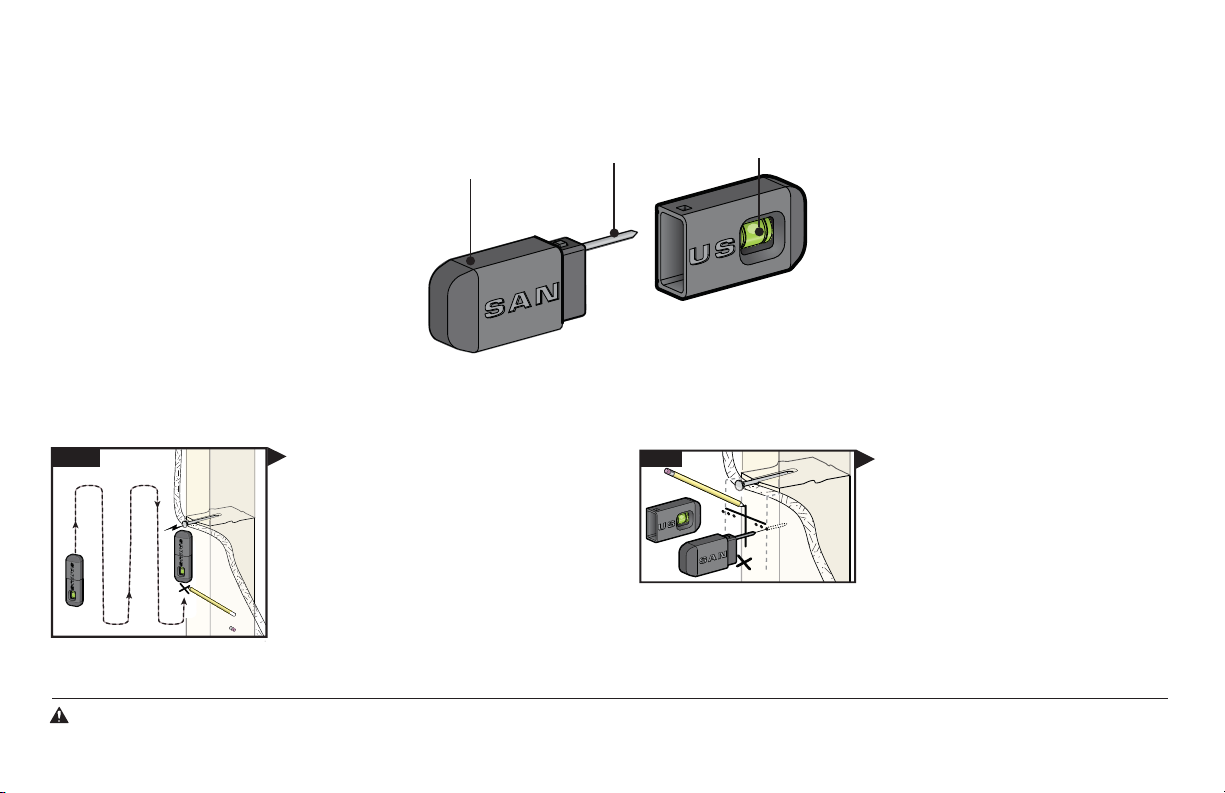
MAGNETIC STUD FINDER
Designed to find your studs and make life easier– included in hardware kit.
TWO SIMPLE STEPS
Step 1
locates screws in drywall
to show exactly where
your studs are
helps find the edges of
your stud within the wall
TO FINDING YOUR STUDS:
Holding it vertically, lightly move the SANUS
Magnetic Stud Finder up and down while
sliding across your wall. The magnet within
will be attracted to the screws in the stud.
Once the magnet has landed on a screw,
place a pencil mark on the wall
directly below the magnet.
You can verify this is a stud by moving the
Magnetic Stud Finder up or down to find
a second or third screw within the wall.
magnet
probing pin
Step 2
level
attaches to your wall plate
for hands free leveling
Pull apart the SANUS Magnetic Stud Finder to
expose the probing pin within. Starting about
1
/2 inch away from the first pencil mark insert
the probing pin into the wall every
it inserts completely into the wall. Once that
happens, you know you've found one edge of
your stud. Repeat this process till you have
found the stud edges and center of the stud.
1
/8 inch until
WARNING:This product contains a magnet. If an implanted medical device such as a pacemaker or implantable cardioverter defibrillator (ICD) is in use, magnetic fields may aect the operation of
those devices, resulting in serious injury or death. If you have an implanted medical device, keep at least 13 cm (5in.) between your device and the magnet. Please consult with your physician or medical
professional prior to using this product.
Page 3
VML5
We’ll Make It Stress-Free
If you have any questions along the way, just give us a call.
1-800-359-5520 (UK: 0800-056-2853) We’re ready to help!
Lo haremos sin estrés
Si tiene preguntas mientras realiza la instalación, llámenos.
1-800-359-5520 (Reino Unido: 0800-056-2853) Estamos listos para ayudarlo.
3
Page 4
IMPORTANT SAFETY INSTRUCTIONS – SAVE THESE INSTRUCTIONS – PLEASE READ ENTIRE MANUAL PRIOR TO USE
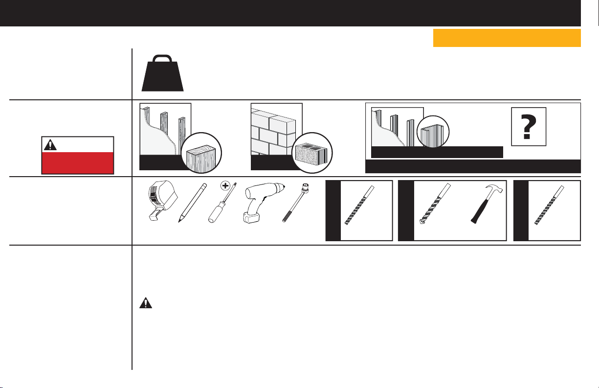
Before getting started, let’s make sure this mount is perfect for you!
1
2
3
4
4
Does your TV weigh
(including accessories)
more than 75 lbs.
(34 kg)?
What is your
wall made of?
CAUTION:
DO NOT install
into drywall alone
Do you have
all the tools
needed?
Ready to
begin?
75 lb
(34 kg)
Perfect! Perfect!
Tape
Measure
Please read through these instructions completely to be sure you’re comfortable with this easy install process.
Also check your TV owner’s manual to see if there are any special requirements for mounting your TV.
If you do not understand these instructions or have doubts about the safety of the installation, assembly or use
of this product, contact Customer Service at 1-800-359-5520 (UK: 0800-056-2853).
CAUTION: Avoid potential personal injuries and property damage!
● This product includes directions and hardware for use with wood stud, solid concrete and concrete block walls –
DO NOT install into drywall alone. For information on how to use this product with steel stud walls contact Customer
Service and ask about the steel stud mounting kit.
● The wall must be capable of supporting fi ve times the weight of the TV and mount combined.
● Do not use this product for any purpose not explicitly specifi ed by manufacturer.
● Manufacturer is not responsible for damage or injury caused by incorrect assembly or use.
No — Perfect!
Yes — This mount is NOT compatible. Visit MountFinder.Sanus.com or call
1-800-359-5520 (UK: 0800-056-2853) to fi nd a compatible mount.
Drywall
with wood
studs?
Pencil Screwdriver
Electric Drill
Solid concrete
or concrete
block?
1/2 in.
(13 mm)
Socket
Wrench
Steel stud kit required [NOT INCLUDED]
Call Customer Service: 1-800-359-5520 (UK: 0800-056-2853)
7/32 in.
(5.5 mm)
Wood
Drill Bit Drill Bit
Wood Stud Install
Para Español ver página 28
3/8 in.
(10 mm)
Concrete
Drill Bit
Concrete Install
Drywall
with steel
studs?
Hammer
Unsure?
1/2 in.
(13 mm)
Steel
Steel Stud Install
Page 5
STEP 1
Attach Brackets to TV
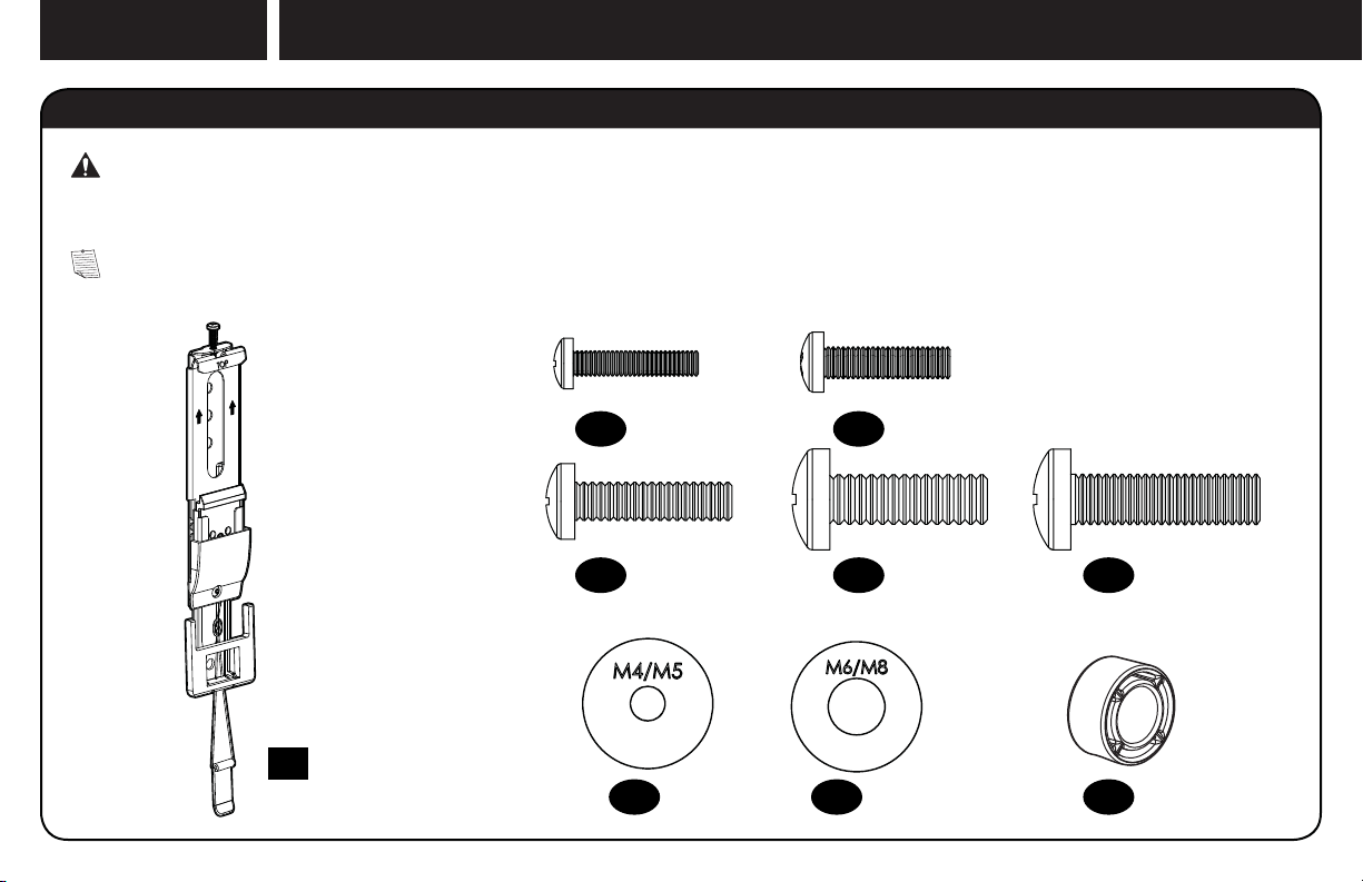
Parts and Hardware for STEP 1
WARNING: This product contains small items that could be a choking hazard if swallowed.
Before starting assembly, verify all parts are included and undamaged. If any parts are missing or damaged, do not return the damaged
item to your dealer; contact Customer Service. Never use damaged parts!
NOTE: Not all hardware included will be used.
TV Screws
TV Brackets
01
x2
M4 x 20mm
x4
02
M6 x 25mm
x4
04
07
M5 x 20mm
x4
03
M8 x 25mm
x4
05
TV Washers Spacers
x4
08
x4
M8x30 mm
06
09
x4
9.5 mm
x4
5
Page 6
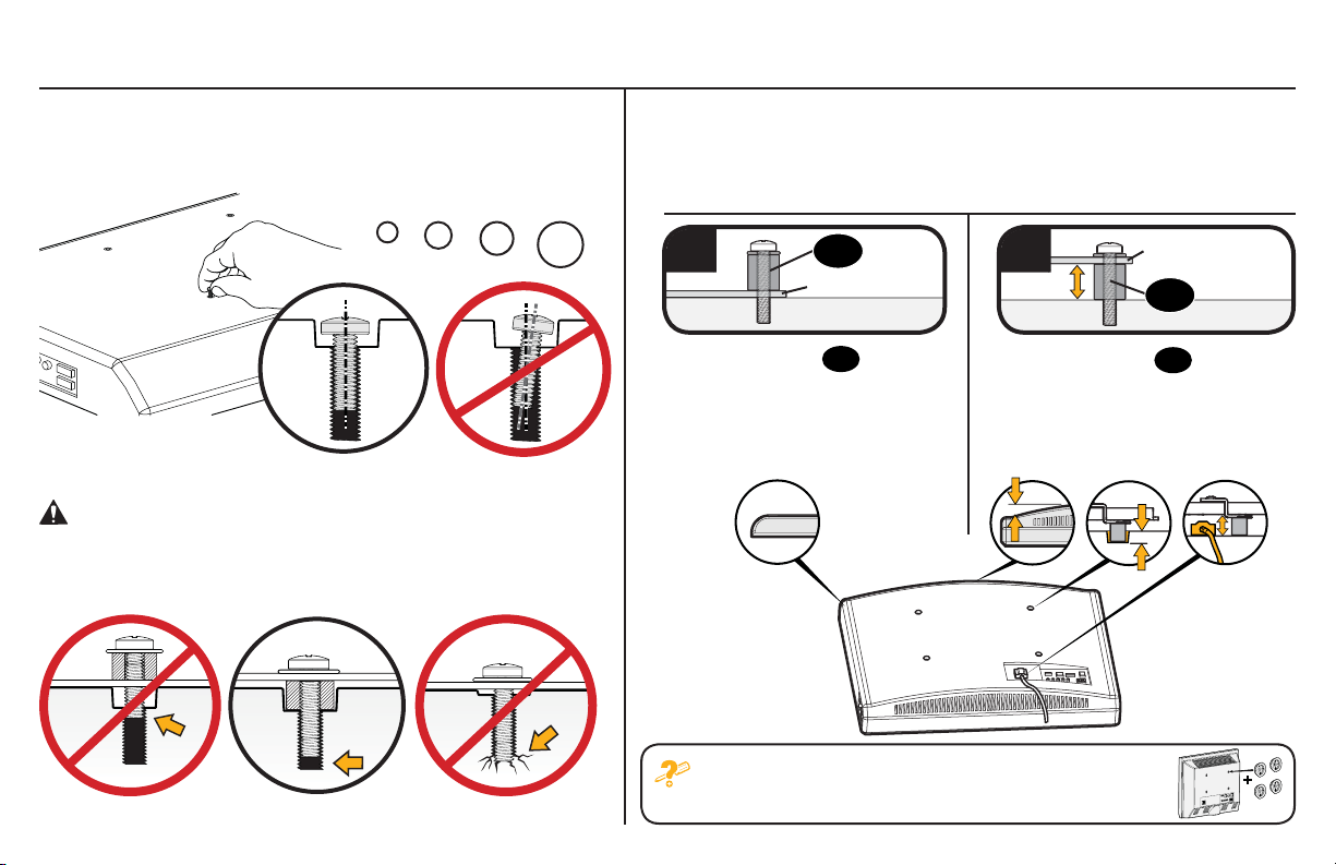
1.1 Select TV Screws
1.2 Spacers
Hand thread screws into the threaded inserts on the back of your TV
to determine which screw diameter (M4, M5, M6, or M8) to use.
M4 M6 M8M5
CAUTION: Verify adequate thread engagement of the
screw/washer/spacer combination on your TV.
Too short will not hold the TV and too long will damage the TV.
Spacers and screws are supplied to install your TV bracket.
Determine your preference for spacer configuration when
attaching your TV bracket.
a
Mount the spacers
TV bracket, for flat back panels
(AND the TV closer to the wall).
09
TV Bracket
09
above the
b
Mount the spacers 09 under the
TV bracket to create extra space
needed for irregular shape TV backs
or large cables.
Round Back CablesInset HolesFlat Back
TV Bracket
09
If your TV included inset spacers or wall mount adapters,
6
Too Short Correct Too Long
see Troubleshooting on PAGE 26.
Page 7
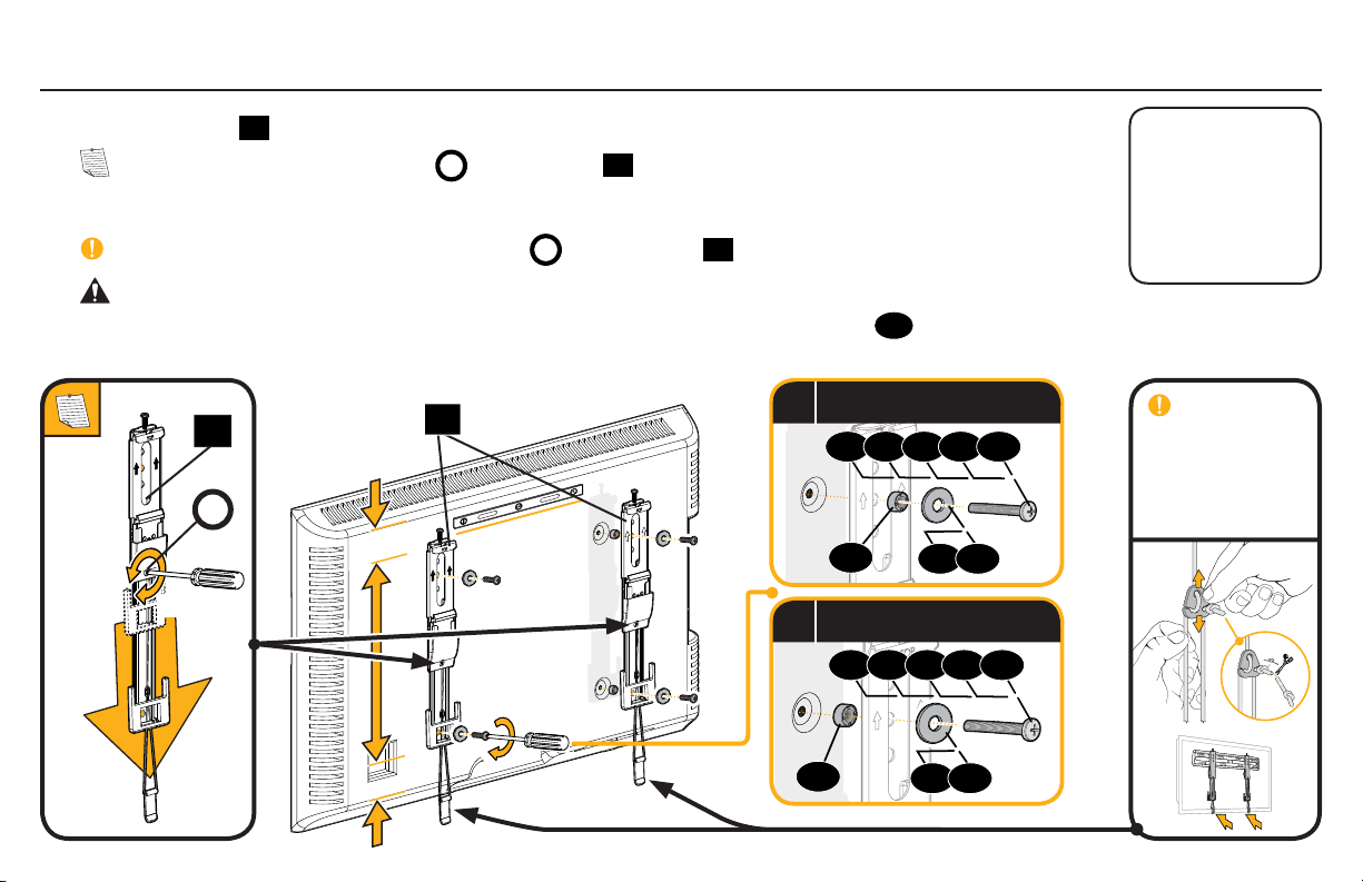
1.3 Attach TV Brackets
Center the TV brackets
NOTE: Loosen the adjustment screws
01
over your TV hole pattern as shown. Be sure to use the same holes and that the brackets are level.
on TV brackets
A
01
to extend the mounting holes over your TV hole pattern.
Install using the spacer, TV screw and washer combination you selected for your TV.
IMPORTANT: Tighten the adjustment screws
on TV brackets
A
01
when finished.
CAUTION: Avoid potential personal injuries and property damage! DO NOT use a power screwdriver for this step.
Tighten screws only until TV Bracket is secured in place. DO NOT overtighten M4 screws
01
01
A
Loosen
Tighten
02
.
Spacer, screw and washer
a
02 03 04 05 06
09
Spacer, screw and washer
b
07 08
02 03 04 05 06
Standard
configurations are
shown. For special
applications, or if
you are uncertain
about your hardware
selection, contact
Customer Service at
1-800-359-5520
.
IMPORTANT:
For ease of access,
straps should
be level with the
bottom of the TV.
09
07 08
7
Page 8
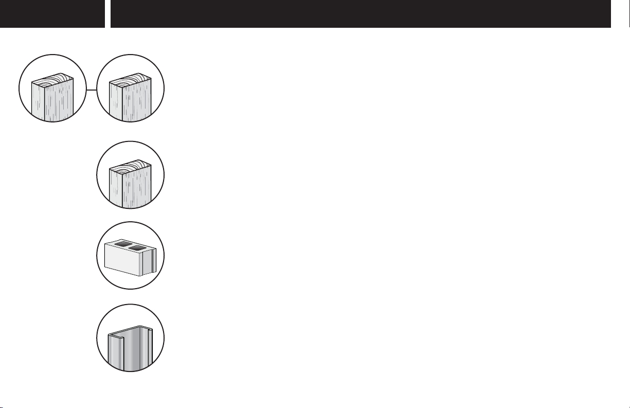
STEP 2 Attach Wall Plate to Wall
For wood stud (Double Stud) installations,
follow STEP 2A on PAGE 10
For wood stud (Single Stud) installations,
follow STEP 2B on PAGE 13
For concrete installations,
follow STEP 2C on PAGE 16
For steel stud installations,
follow STEP 2D on PAGE 18
8
Page 9
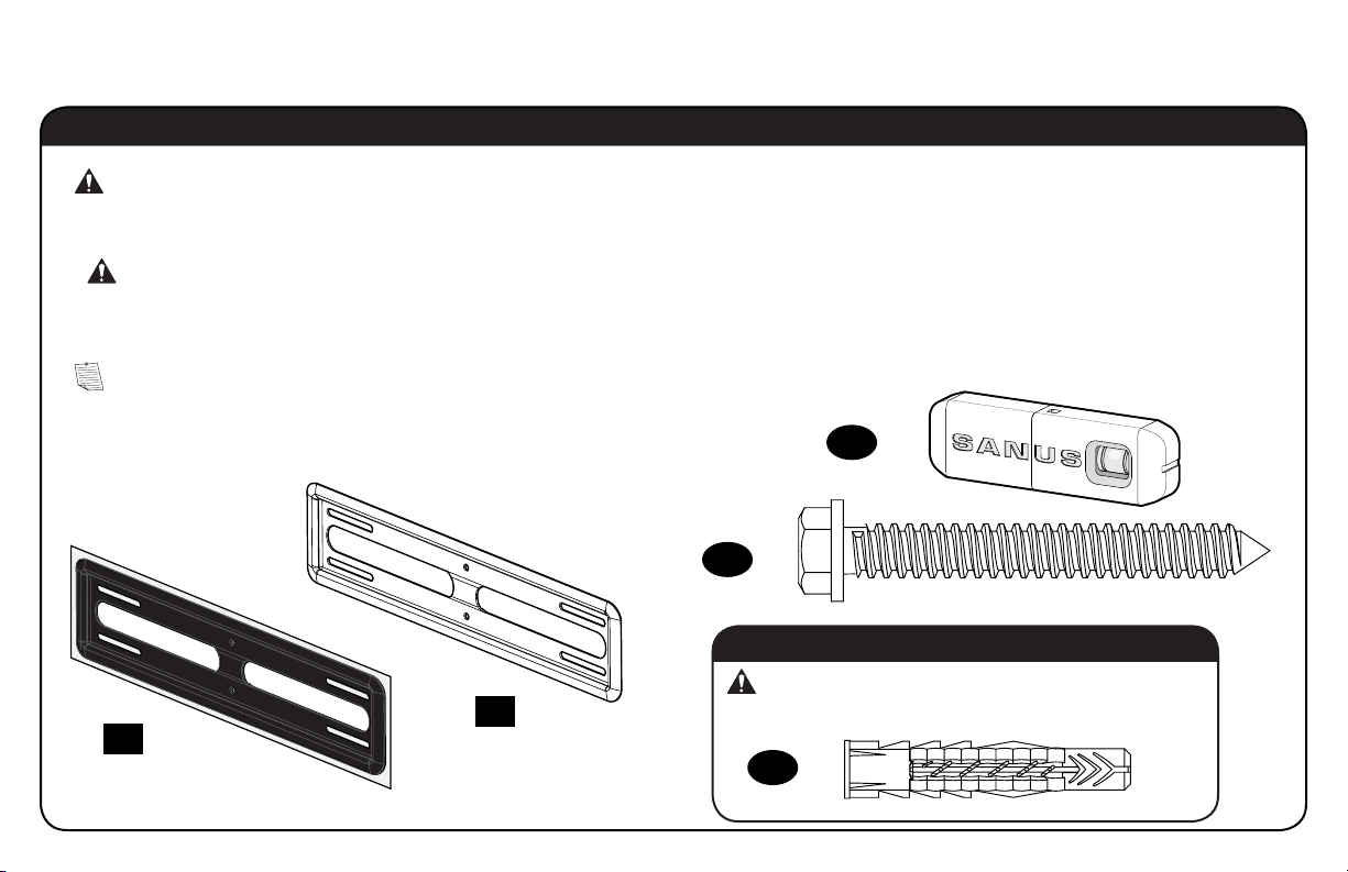
Parts and Hardware for STEP 2
WARNING: This product contains small items that could be a choking hazard if swallowed.
Before starting assembly, verify all parts are included and undamaged. If any parts are missing or damaged, do not return the damaged
item to your dealer; contact Customer Service. Never use damaged parts!
WARNING: This product contains a magnet. If an implanted medical device such as a pacemaker or implantable cardioverter defi brillator
*
(ICD) is in use, magnetic fi elds may a ect the operation of those devices, resulting in serious injury or death. If you have an implanted medical
device, keep at least 13 cm (5 in.) between your device and the magnet. Please consult with your physician or medical professional prior to
using this product.
NOTE: Not all hardware included will be used.
Wall Plate
Template
11
x1
10
Wall Plate
x1
12
x4
13
For concrete installations ONLY
CAUTION: Do not use in drywall or wood
x4
14
Sanus Magnetic Stud Finder*
x1
Lag Bolt
5⁄16 in. x 2 3⁄4 in.
Concrete Anchor
UX10 x 60R
9
Page 10
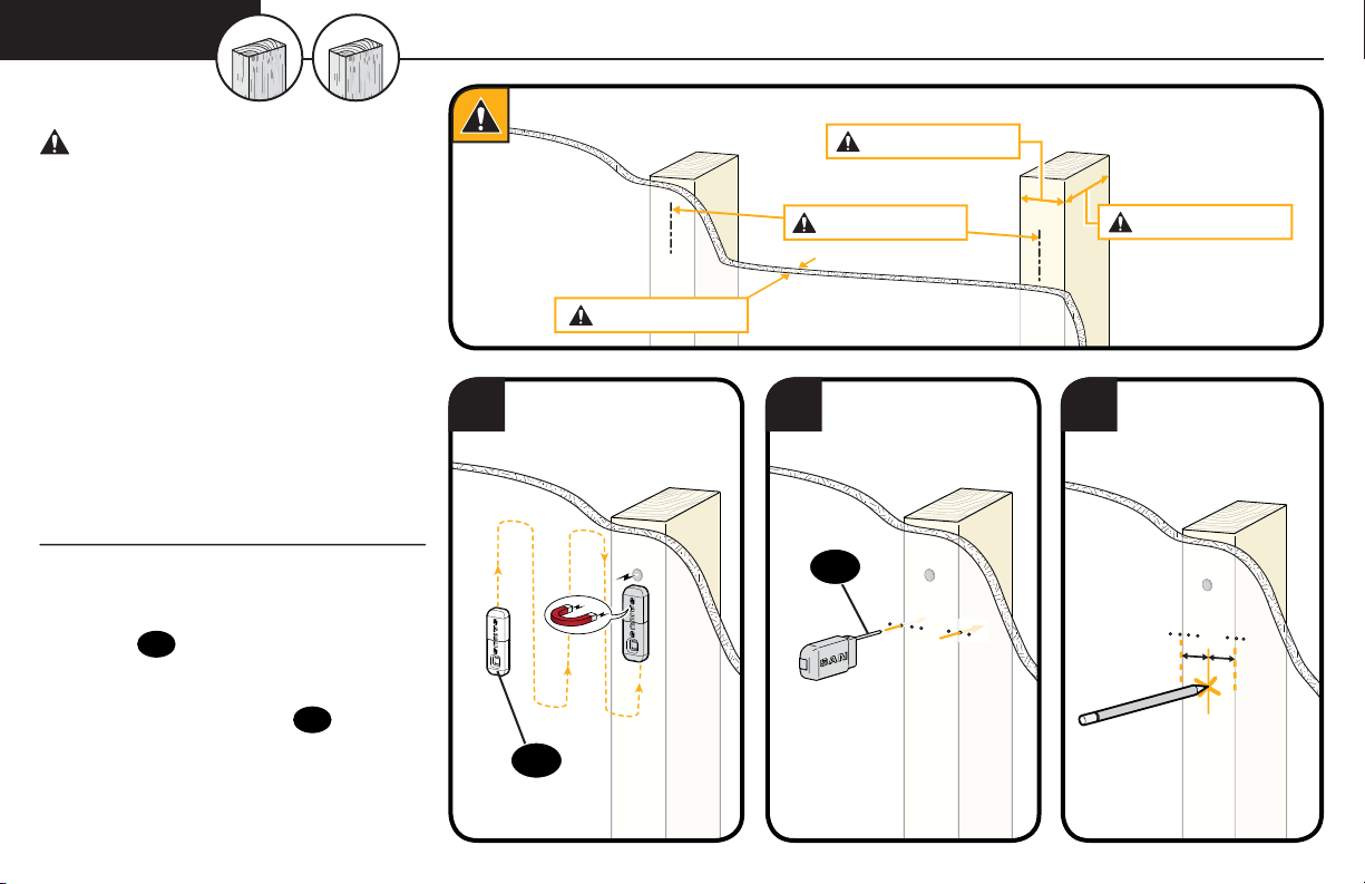
STEP 2A
CAUTION: Avoid potential
personal injuries and property damage!
Wood Stud Option
(Double Stud Install)
Min. 1 1/2 in. (38 mm)
● Drywall covering the wall must not
exceed 5/8 in. (16 mm)
● Minimum wood stud size:
common 2 x 4 in. (51 x 102 mm)
nominal 1½ x 3½ in. (38 x 89 mm)
● Minimum horizontal space between
fasteners: 16 in. (406 mm)
● Stud centers must be verified – not all
walls have conventional 16 in. (406 mm)
or 24 in. (610 mm) stud spacing
1. Locate a nail/screw in the studs
using the Sanus magnetic stud
12
finder
2. Find the edges of the studs using the
probe of the stud finder 12.
3. Mark the centers of the studs with
a pencil.
10
provided.
Min. 16 in. (406 mm)
Max. 5/8 in. (16 mm)
1 2 3
12
12
Min. 3 1/2 in. (89 mm)
Page 11
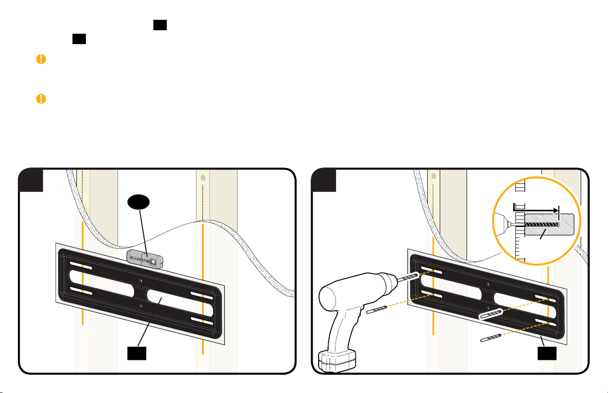
4. Place the wall plate template 10 at your desired height and position the slotted holes over your stud center lines. Level the wall plate
template 10 and tape in place.
IMPORTANT: Be sure you mark and drill into the center of the stud.
5. Drill the four pilot holes using a 7/32 in. (5.5 mm) diameter drill bit.
IMPORTANT: Pilot holes must be drilled to a depth of 3 in. (75 mm).
4 5
12
3 in. (75 mm)
7/32 in.
(5.5 mm)
1010
11
Page 12
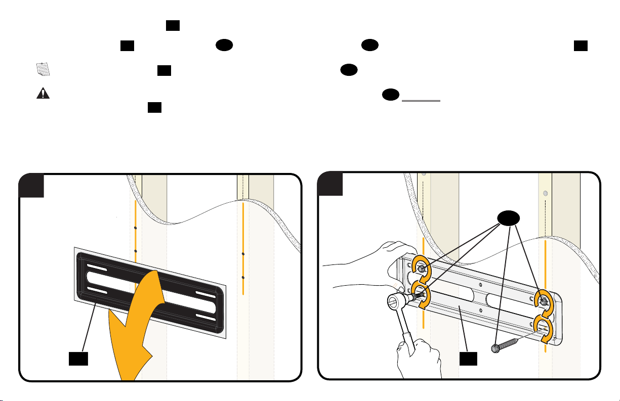
6. Remove the wall plate template
10.
7. Install the wall plate 11 using four lag bolts 13. Firmly tighten all four lag bolts 13 until they are pulled flush against the wall plate
NOTE: Hold the wall plate 11 in place when tightening the first lag bolt 13 to keep the plate from shifting out of place.
CAUTION: Avoid potential personal injury or property damage! All four lag bolts
movement of the wall plate
Go to STEP 3 on PAGE 22.
6
Ensure the wall plate is securely fastened to the wall before continuing on to the next step.
11.
7
13
MUST BE firmly tightened to prevent unwanted
13
11
.
10 11
12
Page 13
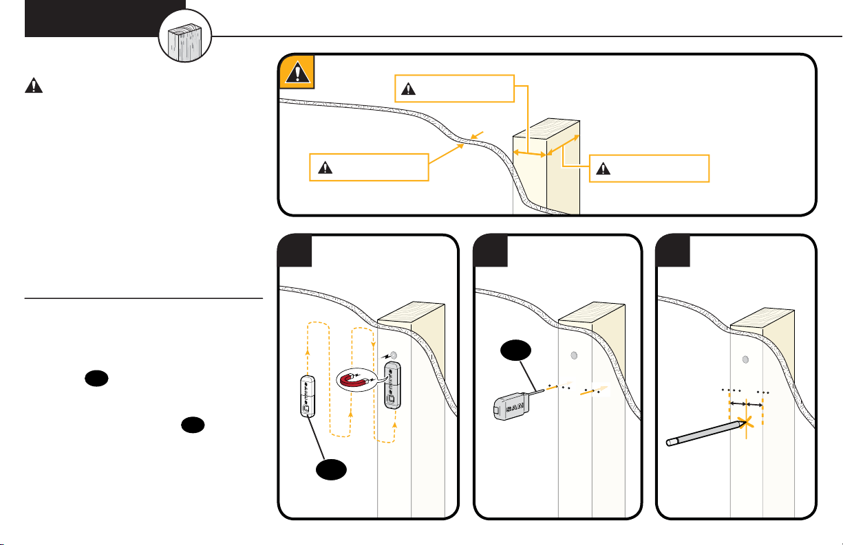
STEP 2B
Wood Stud Option
(Single Stud Install)
CAUTION: Avoid potential
personal injuries and property damage!
● Drywall covering the wall must not
exceed 5/8 in. (16 mm)
● Minimum wood stud size:
common 2 x 4 in. (51 x 102 mm)
nominal 1½ x 3½ in. (38 x 89 mm)
● Minimum horizontal space between
fasteners: 16 in. (406 mm)
● Stud center must be verified
1. Locate a nail/screw in the stud
using the Sanus magnetic stud
12
finder
2. Find the edges of the stud using the
probe of the stud finder 12.
3. Mark the center of the stud with
a pencil.
provided.
Min. 1 1/2 in. (38 mm)
Max. 5/8 in. (16 mm)
Min. 3 1/2 in. (89 mm)
1 2 3
12
12
13
Page 14
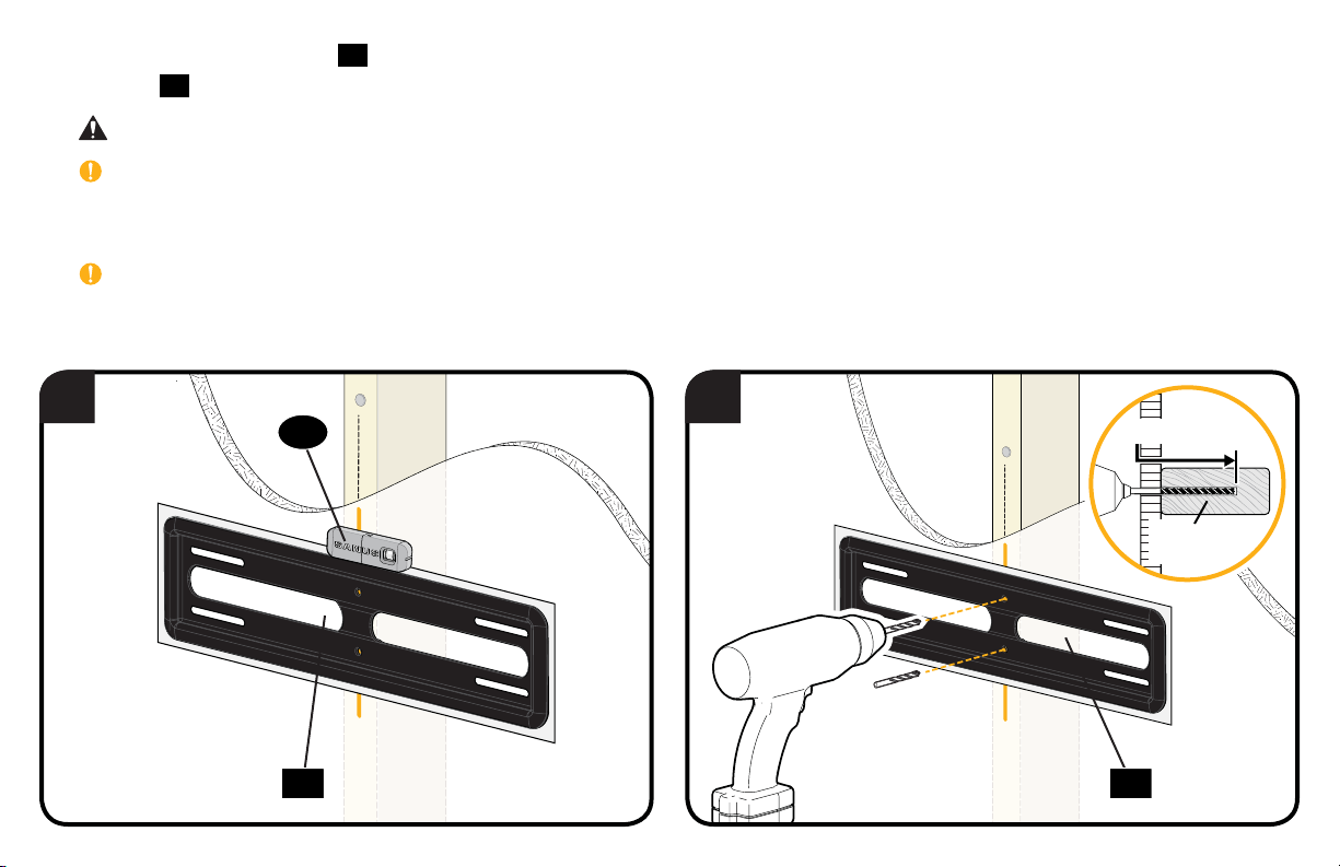
4. Place the wall plate template 10 at your desired height and position the MIDDLE HOLES over your stud center lines. Level the wall plate
template 10 and tape in place.
CAUTION: Avoid potential personal injury or property damage! You MUST install using the center holes in the stud as shown
IMPORTANT: Be sure you mark and drill into the center of the stud.
5. Drill the middle two pilot holes (into the stud) using a 7/32 in. (5.5 mm) diameter drill bit.
IMPORTANT: Pilot holes must be drilled to a depth of 3 in. (75 mm).
4 5
12
3 in. (75 mm)
7/32 in.
(5.5 mm)
10 10
14
Page 15
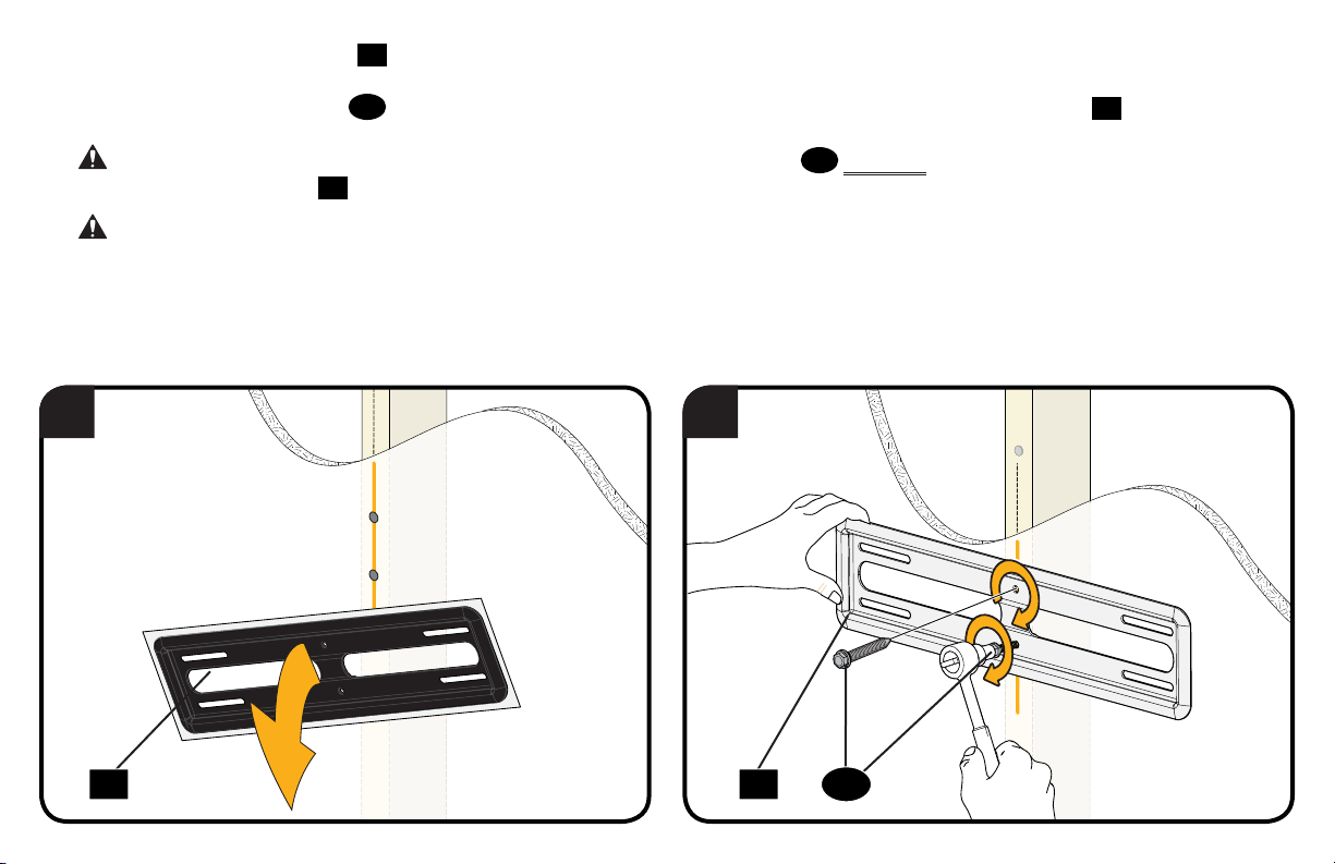
6. Remove the wall plate template
10.
7. Install the middle two lag bolts 13 (into the stud), and firmly tighten until they are pulled flush against the wall plate
CAUTION: Avoid potential personal injury or property damage! Both lag bolts
movement of the wall plate
CAUTION: Avoid potential personal injury or property damage! The middle two lag bolts MUST be installed into a wood stud – this
product was not designed to be used in drywall alone.
Go to STEP 3 on PAGE 22.
11
. Ensure the wall plate is securely fastened to the wall before continuing on to the next step.
13
MUST BE firmly tightened to prevent unwanted
6 7
11
.
1310 11
15
Page 16
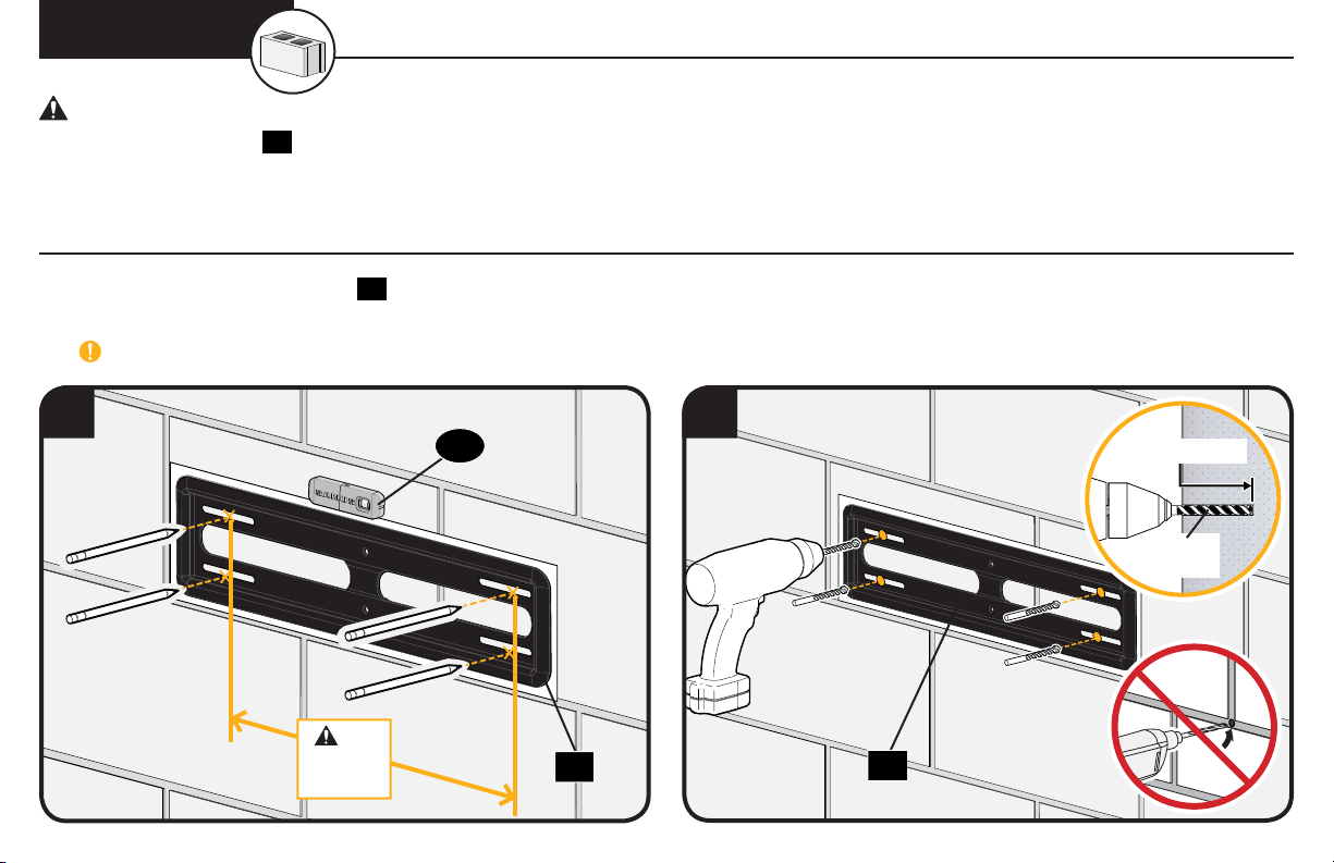
STEP 2C Solid Concrete or Concrete Block Option
CAUTION: Avoid potential personal injuries and property damage!
● Mount the wall plate
● Minimum solid concrete thickness: 8 in. (203 mm)
● Minimum concrete block size: 8 x 8 x 16 in. (203 x 203 x 406 mm)
● Minimum horizontal space between fasteners: 16 in. (406 mm)
directly onto the concrete surface
11
1. Position the wall plate template
2. Drill four pilot holes using a 3/8 in. (10 mm) diameter drill bit.
IMPORTANT: Pilot holes must be drilled to a depth of 3 in. (75 mm). Never drill into the mortar between blocks.
10
on the wall at your desired height. Level the wall plate template and mark the hole locations.
1 2
12
Min.
16 in.
(406 mm)
16
10
3 in. (75 mm)
3/8 in.
(10 mm)
10
Page 17
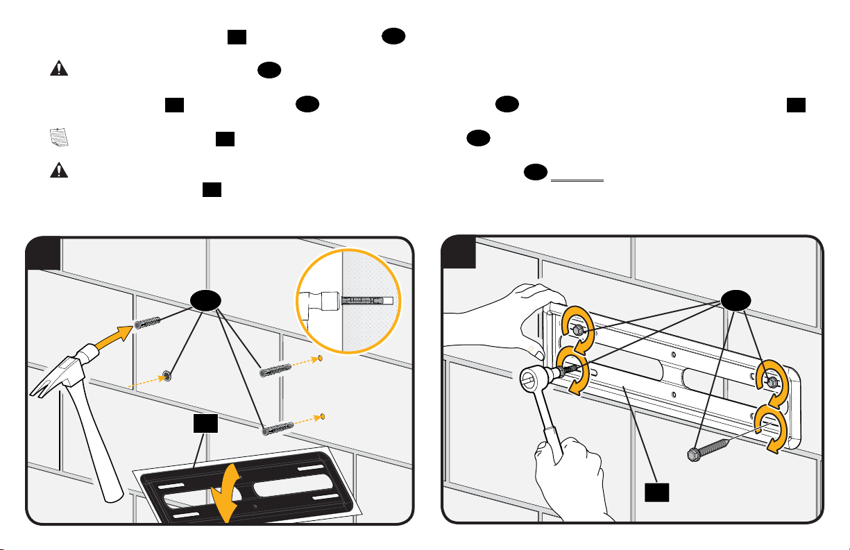
3. Remove the wall plate template
10
and insert four anchors
14
.
CAUTION: Be sure the anchors
4. Install the wall plate 11 using four lag bolts 13. Firmly tighten all four lag bolts 13 until they are pulled flush against the wall plate
NOTE: Hold the wall plate 11 in place when tightening the first lag bolt 13 to keep the plate from shifting out of place.
CAUTION: Avoid potential personal injury or property damage! All four lag bolts
movement of the wall plate
Go to STEP 3 on PAGE 22.
11.
3
14
14
are seated flush with the concrete surface.
13
MUST BE firmly tightened to prevent unwanted
Ensure the wall plate is securely fastened to the wall before continuing on to the next step.
6
13
10
11
.
11
17
Page 18
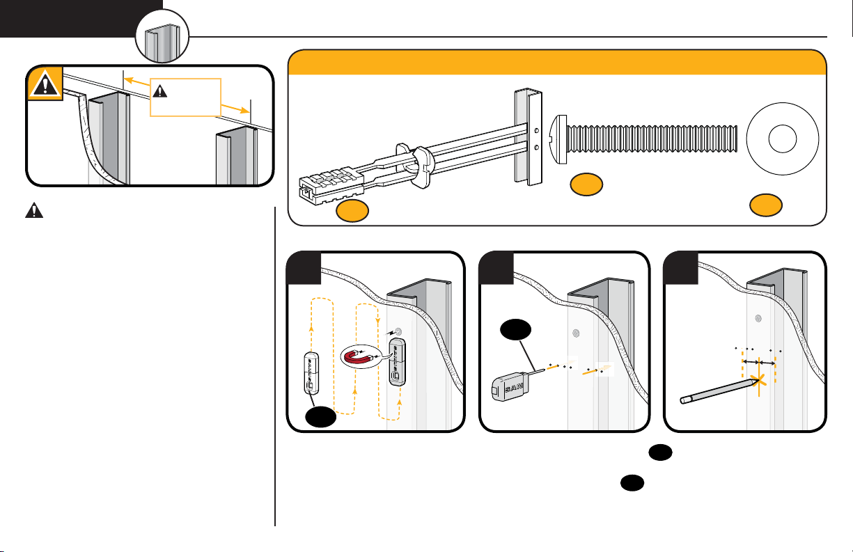
1/4-20 x 1.75
1/4-20 Snap Toggle BB
.734 x .312 x .065 in.
STEP 2D Steel Stud Option (Double and Single Stud Install)
Steel Stud Anchor Kit [NOT INCLUDED]
Min. 16 in.
(406 mm)
CAUTION: Avoid potential personal
injuries and property damage!
● Studs must be at least 2x 4 / 25 ga.
● If back side of wall is unfinished, drywall
must be installed to a minimum of one stud
left and right of the stud(s) being used to
install the mount.
● Drywall must be a minimum of 1/2 in. (13mm)
thick on each side of the studs, and a
minimum clearance of 1 7/8 in. (48 mm)
behind the wall is required.
● This product must be centered on the studs.
● Stud type and structural strength
must conform to the North American
Specification for the Design of Cold-Formed
Steel Structural Members
[362 S 125 18, C-Shape, S - Stud Section].
● Drywall must be secured to studs with
screws 12 in. (304.8 mm) on center.
18
Contact Customer Service at
1-800-359-5520 to have this
additional hardware shipped
directly to you.
Screw
Anchor
x4
S2
x4
S1
1 2 3
13
13
1. Locate a nail/screw in the stud using the Sanus magnetic stud finder 13 provided.
2. Find the edges of the stud using the probe of the stud finder 13.
3. Mark the center of the stud with a pencil.
Washer
S3
x4
Page 19
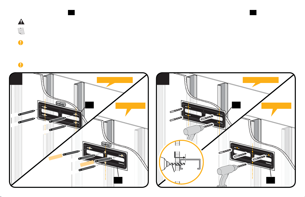
4. Place wall plate template 11 at your desired height and position over your stud center line(s). Level wall plate template 11 and tape in place.
CAUTION: Avoid potential personal injury or property damage! SINGLE STUD installs MUST use the center holes in the stud as shown.
NOTE: For assistance in determining wall plate location, see HeightFinder at sanus.com.
IMPORTANT: Be sure you mark and drill into the center of the stud.
5. Drill the four pilot holes using a 1/2 in. (13 mm) diameter drill bit in the locations illustrated for double stud or single stud installs.
IMPORTANT: Pilot holes must be drilled to a depth of 1 in. (25 mm).
4
STUD
STUD
STUD
STUD
DRYWALL
STUD
STUD
DOUBLE STUD DOUBLE STUD
12 12
SINGLE STUD SINGLE STUD
5
1 in. (25 mm)
DRYWALL
1/2 in.
12 12
(13 mm)
19
Page 20
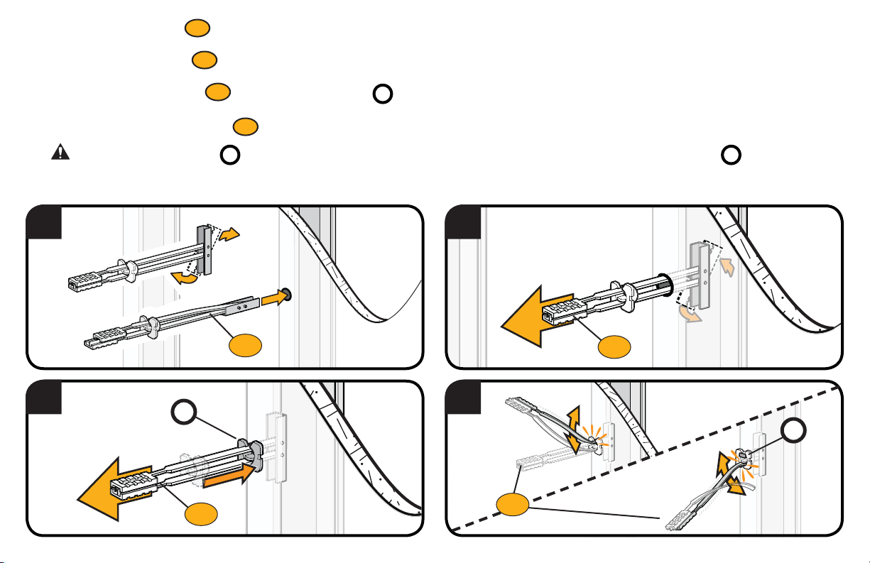
6. Insert the four anchors
7. Pull to rotate the anchor
8. Hold the end of the anchor
S1
into the drilled holes (DOUBLE STUD installs = four in studs. SINGLE STUD installs = two in studs / two in dryway).
*
S1
inside the wall.
*
S1
, while sliding the cap
*
against the drywall.
P
9. Snap off the ends of the anchor
CAUTION: Be sure the cap
6
8
P
S1
S1
to lock in place.
*
is seated against the drywall surface and the ends of the anchor do not extend beyond the cap
P
7
S1
S1
9
S1
- cut if neccessary.
P
P
20
Page 21
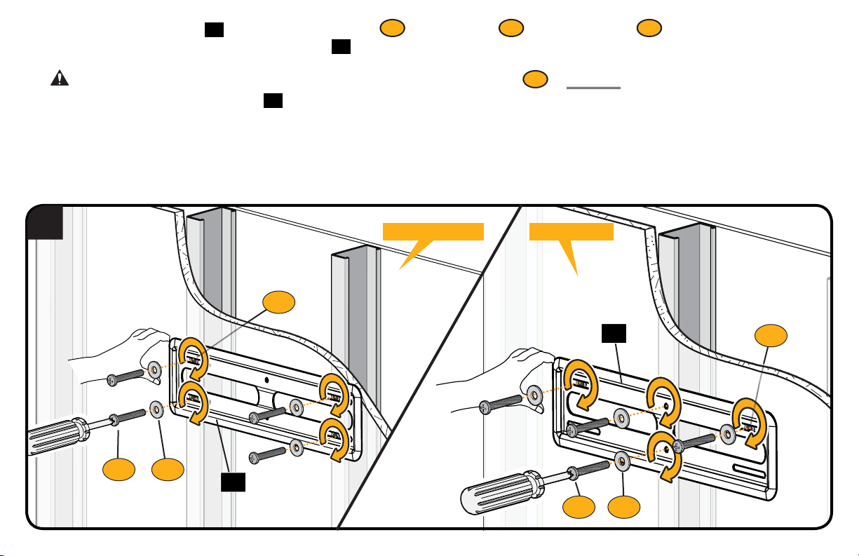
10. Remove wall plate template 11 and install the four screws
the washers are pulled flush against the wall plate
12
.
S2
*
and washers
S3
(into the anchors
*
S1
) and firmly tighten until
*
CAUTION: Avoid potential personal injury or property damage! All four screws
unwanted movement of the wall plate
10
12
. Ensure the wall plate is securely fastened to the wall before continuing on to the next step.
DOUBLE STUD SINGLE STUD
S1
S3S2
12
S2
MUST BE firmly tightened to prevent
*
12
S1
S3S2
21
Page 22

STEP 3
HEAVY! You may need assistance with this step.
1. Hook the TV/brackets 01 onto the wall plate 11.
NOTE: The TV/brackets 01 can be slid anywhere along the wall plate 11 for optimal positioning of your TV.
2. Rest the TV into place against the wall.
3. Press the bottom of the TV against the wall plate 11 until the latches lock the TV in place.
CAUTION: Avoid potential personal injury or property damage! Always make sure your TV brackets 01 are in the locked position
so the TV is securely fastened to the wall plate 11.
Attach TV to Wall Plate
1 2 3
11
01
22
11
01
Page 23
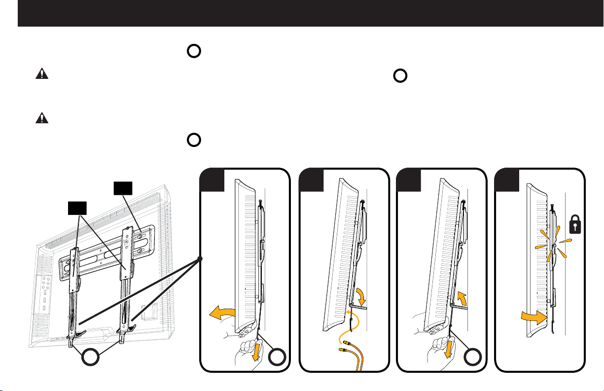
Manage Cables
1. Pull down and hold both release cords
CAUTION: To prevent breaking the locking latch: always pull and hold the release cords
2. Temporarily rest the TV on the kick stands while assembling the cables on the TV.
while gently pulling the bottom of the TV away from the wall until the kick stands fall into place.
R
CAUTION: TV is not secured to the wall when it is in the kick stand position. Assistance is recommended for this step.
3. Pull down and hold both release cords
4. Gently rest the TV back until the brackets click and lock the TV in place.
11
while gently pulling the bottom of the TV away from the wall to unlock the kick stands.
R
1 2 3 4
01
down while pulling the TV away from the wall.
R
R
RR
23
Page 24
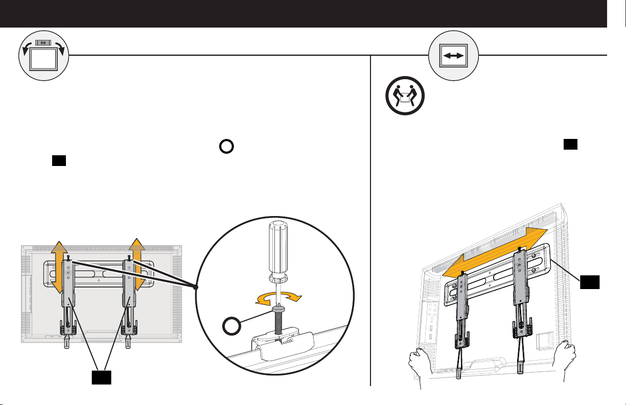
Adjustments
LEVEL
To level your TV, turn the level adjustment screw
bracket 01 to raise or lower that respective side of the TV.
on the top of either TV
S
Lower
S
Raise
TV LATERAL SHIFT
HEAVY! You may need
assistance with this step.
Slide the TV left or right along the wall plate 11
to reposition.
11
01
24
Page 25
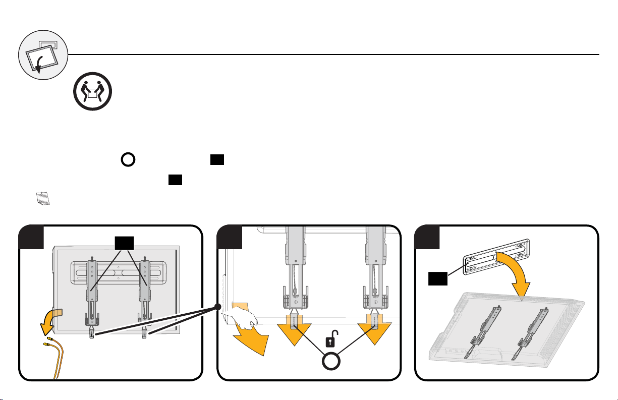
REMOVING THE TV
HEAVY! You may need assistance with this step.
1. Disconnect all cables from the TV (see Manage Cables on PAGE 23).
2. Pull the release cords
3. Lift the TV up and off the wall plate 11.
NOTE: To rehang the TV, follow the procedures in STEP 3 on PAGE 22.
1 2 3
on the TV brackets 01 while gently pulling the bottom of the TV away from the wall.
R
01
R
11
25
Page 26
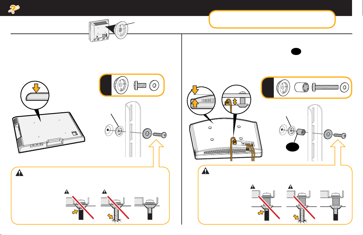
Troubleshooting
TV supplied spacers
TV Supplied
Spacers
If you are uncertain about your hardware selection,
contact Customer Service at 1-800-359-5520.
a: Use your TV supplied spacer for flat back TVs (AND you want
your TV closer to the wall).
FLAT BACK
a
TV Supplied
Spacer
CAUTION: Avoid potential injury or property damage!
Use the correct screw length for adequate thread engagment.
– Too short will
not hold the TV.
– Too long will
damage the TV.
Too Short
Too Long
Correct
b: Use your TV supplied spacer and spacer
● Round (irregular) back TVs ● Extra space needed for cables
ROUND BACK CABLES
09
for:
b
TV Supplied
Spacer
09
CAUTION: Avoid potential injury or property damage!
Use the correct screw length for adequate thread engagment.
Too Short
– Too short will
not hold the TV.
– Too long will
damage the TV.
Too Long
Correct
26
Page 27
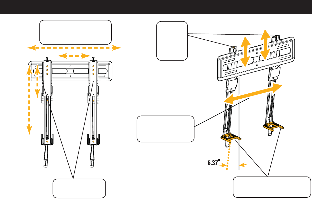
Features
TV bracket expands to fi t TV
hole patterns from 200 x 200 mm
up to 400 x 400 mm
Level
adjustments
create a
worry-free
installation
Brackets adjust side to
side within the wall plate
for optimal positioning
Locking mechanisms
for added security
Kick stands hold TV from wall to
create room to attach cables
27
Page 28
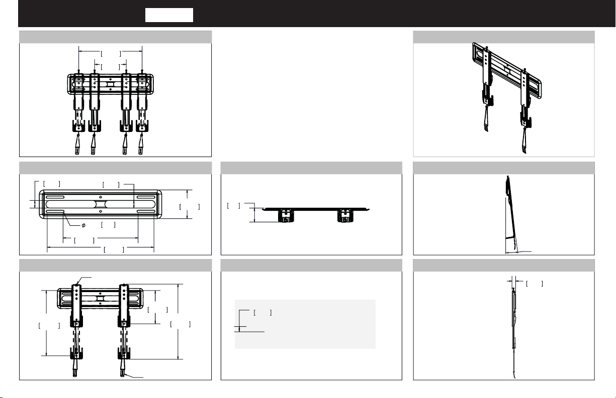
Dimensions
in. [mm]
TV INTERFACE
WALL PLATE
1.32
33.5
13.05
331.5
0.38
15.75
400.0
7.87
200.0
1.32
33.5
9.5
18.56
471.5
FULLY ASSEMBLED MOUNT
16.23
412.3
1" POST INSTALL
HEIGHT ADJUST
8.27
210.0
18.72
475.5
5.00
127.0
3-D
TOP VIEW - EXTENDED
2.78
70.6
TOP VIEW - RETRACTED
0.91
23.0
SIDE VIEW - EXTENDED
6.24°
SIDE VIEW - RETRACTED
0.91
23.0
ADJUSTABLE
28
CORD LEGNTH
Page 29

29
Page 30
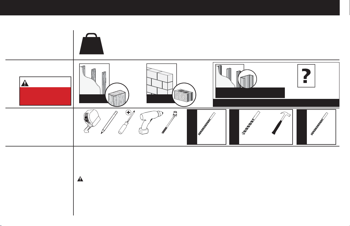
ESPAÑOL
INSTRUCCIONES DE SEGURIDAD IMPORTANTES. CONSÉRVELAS. LEA TODO EL MANUAL ANTES DE UTILIZAR ESTE PRODUCTO.
Antes de comenzar, verifiquemos que este soporte sea el ideal para sus necesidades.
¿Su televisor pesa
1
más de 34 kg
(75 lb), incluidos
los accesorios?
¿De qué está
2
hecha su pared?
PRECAUCIÓN:
NO lo instale en
tabiques únicamente
de yeso
¿Tiene
3
todas las
herramientas
necesarias?
¿Listo para
4
comenzar?
30
No — ¡Perfecto!
34 kg
(75 lb)
¡Perfecto! ¡Perfecto!
Lea estas instrucciones en su totalidad para estar seguro de sentirse cómodo con este fácil proceso de instalación. Consulte
también el manual del usuario de su televisor para ver si existe algún requisito especial para instalar su televisor en la pared.
Si no entiende las instrucciones o si tiene dudas acerca de la seguridad de la instalación, del ensamblado o del uso del
producto, póngase en contacto con el servicio de atención al cliente al 1-800-359-5520 (Reino Unido: 0800-056-2853).
Sí — Este soporte NO es compatible. Visite MountFinder.Sanus.com o llame al
1-800-359-5520 (Reino Unido: 0800-056-2853) para encontrar un soporte compatible.
¿Tabiques
de yeso con
montantes de
madera?
DestornilladorCinta métrica
Lápiz
Taladro eléctrico
¿Hormigón
sólido o
bloques de
cemento?
13 mm
(1/2”)
Llave de tubo
Se requiere el kit para montantes
de acero [no está incluido]
Llame al 1-800-359-5520 (Reino Unido: 0800-056-2853)
5,5 mm
Paredes con
(7/32'')
Madera
Broca BrocaBroca
montantes de madera
¿Tabiques
de yeso con
montantes
de acero?
hormigón
paredes con de
10 mm
(3/8'')
Hormigón
Martillo
¿No está
seguro?
13 mm
paredes con
montantes de acero
(1/2")
Acero
PRECAUCIÓN: Evite posibles lesiones personales y daños materiales.
● Este producto incluye instrucciones y elementos de sujeción para su instalación en paredes con montantes de madera, en superficies de
hormigón y sobre bloques de cemento. NO lo instale en tabiques únicamente de yeso.
paredes con montantes de acero, póngase en contacto con el servicio de atención al cliente y pregunte por el kit de montaje en montantes de acero.
● La pared debe soportar cinco veces el peso del televisor y del soporte juntos.
● No utilice este producto para ningún otro propósito que no sea el explícitamente especificado por el fabricante.
● El fabricante no se responsabiliza por ningún daño o lesión resultante del montaje incorrecto o de uso indebido.
Para obtener información sobre cómo usar este producto en
Page 31
ESPAÑOL
PASO 1 Colocar las placas de sujeción en el televisor
Ver página 5
Piezas y elementos de sujeción para el PASO 1
ADVERTENCIA: Este producto contiene piezas pequeñas que, si fuesen tragadas, podrían producir asfixia.
Antes de iniciar el ensamblaje, compruebe que todas las piezas estén incluidas y en buenas condiciones. Si faltan piezas o alguna está dañada,
no devuelva el artículo al distribuidor; póngase en contacto con el servicio de atención al cliente. Nunca utilice piezas deterioradas.
NOTA: No todos los accesorios incluidos deberán utilizarse.
1,1 Seleccionar los tornillos del televisor
Enrosque manualmente los tornillos en los encastres roscados del dorso del televisor a fin de determinar qué diámetro de tornillos (M4, M5, M6
o M8) utilizar.
PRECAUCIÓN: Verifique que la combinación de tornillo y separador enrosque correctamente en su televisor.
Si el tornillo es demasiado corto, el televisor no se sostendrá; si es demasiado largo, dañará el televisor.
1,2 Separadores
Los separadores y tornillos se proporcionan para instalar la placa de sujeción de su televisor.
Determine cuál es su preferencia para la configuración de los separadores al fijar la placa de sujeción de su televisor.
Instale los separadores 09 encima de la placa de sujeción de su televisor, de modo que la placa de sujeción quede cerca de la superficie
del televisor para los paneles planos posteriores.
Instale los separadores 09 debajo de la placa de sujeción del televisor para crear más espacio para los televisores con forma irregular en
la parte posterior o cables extensos.
1,3 Fijar las placas de sujeción del televisor
Centre las placas de sujeción
las placas de sujeción estén niveladas.
NOTA: Afloje los tornillos de ajuste
Coloque la combinación de separador, tornillo y arandela que seleccionó para su televisor.
IMPORTANTE: Cuando termine, ajuste los tornillos de ajuste
IMPORTANTE: Para facilitar el acceso, las correas deben estar niveladas con la parte inferior del televisor.
PRECAUCIÓN: Evite posibles lesiones físicas y daños materiales. NO utilice un destornillador eléctrico para este paso. Apriete los tornillos
sólo hasta el soporte de la TV se fi ja en su lugar. No apriete demasiado los tornillos M4
Se ilustran las configuraciones estándar. Si desea información sobre aplicaciones especiales o si tiene dudas sobre la elección de los elementos de fijación,
contáctese con el servicio de atención al cliente. 1-800-359-5520 (Reino Unido: 0800-056-2853)
01
sobre el patrón de orificios del televisor como se muestra. Asegúrese de usar los mismos orificios y de que
de las placas de sujeción del televisor
A
01
para extender los orificios de montaje sobre el patrón de orificios del televisor.
sobre las placas de sujeción 01.
A
02
.
31
Page 32
ESPAÑOL
PASO 2 Fijar la placa mural a la pared
Ver página 8
Para instalaciones sobre montantes de madera (doble montante), siga el PASO 2A en la PÁGINA 10
Para instalaciones sobre montantes de madera (un solo montante), siga el PASO 2B en la PÁGINA 13
Para instalaciones en paredes de hormigón, siga el PASO 2C en la PÁGINA 16
Para instalaciones sobre montantes de acero, siga el PASO 2D en la PÁGINA 18
Piezas y elementos de sujeción para el PASO 2
ADVERTENCIA: Este producto contiene piezas pequeñas que, si fuesen tragadas, podrían producir asfixia.
Antes de iniciar el ensamblaje, compruebe que todas las piezas estén incluidas y en buenas condiciones. Si faltan piezas o alguna está dañada,
no devuelva el artículo al distribuidor; póngase en contacto con el servicio de atención al cliente. Nunca utilice piezas deterioradas.
* ADVERTENCIA: Este producto contiene un imán. Si utiliza un dispositivo médico implantado como un marcapasos o un desfibrilador automático
implantable (DAI), los campos magnéticos pueden afectar el funcionamiento de esos dispositivos y causar heridas de gravedad o la muerte. Si tiene
un dispositivo médico implantado, mantenga una distancia de al menos 13 cm (5 pulgadas) entre su dispositivo y el imán. Consulte a su médico antes
de utilizar este producto.
NOTA: No todos los accesorios incluidos deberán utilizarse.
SOLO para instalaciones en hormigón
x4
PRECAUCIÓN: No usar en placas de yeso o montantes de madera
PASO 2A
Opción para montantes de madera (Instalación de doble montante)
14
UX10 x 60R
PRECAUCIÓN: Evite lesiones y daños materiales.
● El yeso que recubre la pared no debe exceder los 16 mm (5/8").
● Tamaño mínimo del montante de madera: común 51mm x 102 mm (2" x 4") (nominal 38 mm x 89 mm (11/2" x 31/2").
● Espacio horizontal mínimo entre los elementos de sujeción: 406 mm (16 pulgadas)
32
● Se deben verificar las partes centrales de los pernos, no todas las paredes tienen una separación convencional de 406 mm (16")
Page 33

ESPAÑOL
1. Encuentre un clavo/tornillo en los montantes con el detector magnético de bordes de montantes Sanus 12 incluido.
2. Encuentre los bordes de los montantes con el detector magnético de bordes de montantes 12.
3. Marque los centros de los montantes con un lápiz.
4. Coloque la plantilla de placa mural 10 a la altura que desee y posicione los orificios en forma de ranura sobre las líneas centrales del
montante. Nivele la plantilla de la placa mural 10 y fíjela con cinta adhesiva en el lugar.
IMPORTANTE: Asegúrese de marcar y perforar el centro del montante.
5. Haga los cuatro orificios guía con una mecha de 5,5 mm (7/32") de diámetro.
IMPORTANTE: Los orificios guía deben realizarse hasta una profundidad de 75 mm (3").
6. Retire la plantilla de la placa mural
7. Instale la placa mural 11 usando quatro tornillos tirafondo 13 . Apriete con firmeza los cuatro pernos tirafondos
en la placa de pared 11.
NOTA: Sostenga la placa mural 11 en su lugar mientras ajusta el primer perno 13 para evitar que se mueva fuera de su sitio.
PRECAUCIÓN: Evite posibles lesiones personales y daños materiales. Los cuatro tornillos tirafondo
firmemente para evitar que la placa mural se desplace
proceder con el siguiente paso.
Continúe con el PASO 3 en la PÁGINA 22.
10
.
13
hasta que queden encajados
13
DEBEN ESTAR apretados
11
. Asegúrese de que la placa mural está fijada con seguridad a la pared antes de
33
Page 34
ESPAÑOL
PASO 2B
PRECAUCIÓN: Evite lesiones y daños materiales.
● El yeso que recubre la pared no debe exceder los 16 mm (5/8").
● Tamaño mínimo del montante de madera: común 51mm x 102 mm (2" x 4") (nominal 38 mm x 89 mm (11/2" x 31/2").
● Se debe verificar la parte central
1. Encuentre un clavo/tornillo en el montante con el detector magnético de bordes de montantes Sanus 12 incluido.
2. Encuentre los bordes del montante con el detector magnético de bordes de montante 12.
3. Marque el centro del montante con un lápiz.
4. Coloque la plantilla de placa mural 10 a la altura que desee y posicione los orificios intermedios sobre las líneas centrales del montante.
Nivele la plantilla de la placa mural 10 y fíjela con cinta adhesiva en el lugar.
Opción para montantes de madera (Instalación de un solo montante)
PRECAUCIÓN: Evite lesiones y daños materiales. Usted debe instalar utilizando los agujeros centrales en el montante de madera como se muestra.
IMPORTANTE: Asegúrese de marcar y perforar el centro del montante.
5. Haga los dos orificios guía intermedios (en el montante) con una mecha de 5,5 mm (7/32") de diámetro.
IMPORTANTE: Los orificios guía deben realizarse hasta una profundidad de 75 mm (3").
6. Retire la plantilla de la placa mural
7. Coloque los dos pernos tirafondo intermedios
PRECAUCIÓN: Evite posibles lesiones personales y daños materiales. Ambos tornillos tirafondo
para evitar que la placa mural se desplace
siguiente paso.
10
.
13
(en el montante) y apriete firmemente hasta que estén nivelados en la placa mural
13
DEBEN ESTAR apretados firmemente
11
. Asegúrese de que la placa mural está fijada con seguridad a la pared antes de proceder con el
PRECAUCIÓN: Evite el riesgo de lesiones y daños materiales. Los dos pernos tirafondo intermedios DEBEN ser instalados en el montante - este
producto no fue diseñado para ser utilizado en el tabique de yeso solo.
Continúe con el PASO 3 en la PÁGINA 22.
11
.
34
Page 35
PASO 2C Opción para hormigón sólido o bloques de cemento
PRECAUCIÓN: Evite lesiones y daños materiales.
● Instale la placa mural
● Espesor mínimo del hormigón: 203 mm (8")
● Tamaño mínimo del bloque de cemento: 203 x 203 x 406 mm (8" x 8" x 16")
● Espacio horizontal mínimo entre los elementos de sujeción: 406 mm (16 pulgadas)
directamente sobre la superficie de hormigón.
11
ESPAÑOL
1. Coloque la plantilla de la placa mural
de los orificios.
2. Haga los cuatro orificios guía con una mecha de 10 mm (3/8") de diámetro.
IMPORTANTE: Los orificios guía deben realizarse hasta una profundidad de 75 mm (3"). Nunca perfore el cemento que une
los bloques.
3. Retire la plantilla de la placa mural
PRECAUCIÓN: Cerciórese de que los anclajes
4. Coloque los dos pernos tirafondos inferiores
placa de pared 11.
NOTA: Sostenga la placa mural 11 en su lugar mientras ajusta el primer perno 13 para evitar que se mueva fuera de su sitio.
PRECAUCIÓN: Evite posibles lesiones personales y daños materiales. Los cuatro tornillos tirafondo
firmemente para evitar que la placa mural se desplace
proceder con el siguiente paso.
Continúe con el PASO 3 en la PÁGINA 22.
10
en la pared a la altura que desee. Nivele la plantilla de la placa mural y marque la ubicación
10
e inserte cuatro anclajes
14
13
. Apriete con firmeza los cuatro pernos tirafondos
queden nivelados respecto de la superficie de hormigón.
11
. Asegúrese de que la placa mural está fijada con seguridad a la pared antes de
14
.
13
hasta que queden encajados en la
13
DEBEN ESTAR apretados
35
Page 36
ESPAÑOL
PASO 2D Opción para montantes de acero
PRECAUCIÓN: Evite posibles lesiones personales y daños materiales.
• LAS VIGAS DEBEN SER AL MENOS DE 2X4” / CALIBRE 25.
• S
I LA PARTE POSTERIOR DE LA PARED NO PRESENTA UN ACABADO, SE DEBE APLICAR MAMPOSTERÍA AL MENOS EN UNA DE LAS VIGAS A LA IZQUIERDA Y A LA DERECHA QUE SE EMPLEEN PARA INSTALAR EL SOPORTE.
• LA MAMPOSTERÍA DEBE TENER UN ESPESOR MÍNIMO DE 13 MM EN CADA LADO DE LAS VIGAS Y UNA HOLGURA MÍNIMA DE 48 MM POR DETRÁS DE LA PARED.
• ESTA PRODUCTO DEBE CENTRARSE EN LAS VIGAS.
• EL TIPO DE VIGA Y LA RESISTENCIA ESTRUCTURAL DEBEN AJUSTARSE A LA NORMATIVA NORTEAMERICANA PARA EL DISEÑO DE COMPONENTES ESTRUCTURALES DE ACERO FORJADO EN FRÍO. [SECCIÓN
362 S 125 18, FORMA EN C, VIGA S]
• LA MAMPOSTERÍA SE DEBE FIJAR CON TORNILLOS A 30,5 CM DEL CENTRO DE LAS VIGAS.
El Kit de instalación de un solo montante no está incluido. Comuníquese con el servicio de atención al cliente al 1-800-359-5520 para solicitar que le
enviemos los elementos de sujeción adicionales.
1. Encuentre un clavo/tornillo en el montante con el detector magnético de bordes de montantes Sanus 13 incluido.
2. Encuentre los bordes del montante con el detector magnético de bordes de montante 13.
3. Marque el centro del montante con un lápiz.
4. Coloque la plantilla de placa mural 11 a la altura que desee y posicione los orificios intermedios sobre las líneas centrales del montante.
Nivele la plantilla de la placa mural 11 y fíjela con cinta adhesiva en el lugar.
PRECAUCIÓN: Evite lesiones y daños materiales. Usted debe instalar utilizando los agujeros centrales en el montante de acero como se muestra.
NOTA: Si necesita ayuda para determinar la ubicación de la placa mural, utilice la herramienta HeightFinder disponible en sanus.com.
IMPORTANTE: Asegúrese de marcar y perforar el centro del montante.
5. Haga los dos orificios guía intermedios (en el montante) con una mecha de 13 mm (1/2") de diámetro.
IMPORTANTE: Los orificios guía deben realizarse hasta una profundidad de 25 mm (1").
6. Retire la plantilla de la placa mural
36
y inserte quatro anclajes
11
S1
en los orificios superiores externos (en el tabique de yeso).
*
Page 37
7. Tire para girar los anclajes
8. Sostenga el extremo del anclaje
9. Rompa los extremos del anclaje
PRECAUCIÓN: Asegúrese de que la tapa
extienden más allá de la tapa
10. Coloque los cuatro pernos tirafondo
placa mural
12
.
S1
dentro en el tabique.
*
S1
, mientras desliza la tapa
*
S1
para que encaje en su lugar.
*
- cortar si es necesario.
P
S2
y arandelas
*
contra el tabique de yeso.
P
está asentada contra la superficie el tabique de yeso y los extremos del anclaje no se
P
S3
*
(en el anclajes
S1
) y apriete firmemente hasta que estén nivelados en la
*
PRECAUCIÓN: Evite posibles lesiones personales y daños materiales. Los cuatro tornillos tirafondo
firmemente para evitar que la placa mural se desplace
12
.
S2
DEBEN ESTAR apretados
*
ESPAÑOL
Fijar el televisor a la placa muralPASO 3
Ver página 22
¡ELEMENTO PESADO! Es posible que necesite ayuda en este paso.
01
1. Cuelgue el módulo televisor-placas
NOTA: El módulo televisor-placas 01 se puede deslizar hacia cualquier parte junto con la placa mural 11 para lograr un posicionamiento
óptimo de su televisor.
2. Apoye el televisor en su lugar contra la pared.
3. Presione la parte inferior del televisor contra la placa mural 11 hasta que las placas de sujeción fijen el televisor en su lugar.
en la placa mural 11.
PRECAUCIÓN: Evite el riesgo de lesiones y daños materiales. Siempre asegúrese de que las placas de sujeción del televisor
estén en la posición bloqueada, de modo que el televisor quede bien sujeto a la placa mural 11.
01
37
Page 38
ESPAÑOL
Organizar los cables
1. Jale hacia abajo y sostenga ambos cordones de desenganche
de la pared hasta que los pies de apoyo se ubiquen en su lugar.
mientras tira con cuidado de la parte inferior del televisor para separarlo
R
Ver página 23
PRECAUCIÓN: Para que el pasador de seguridad no se rompa, siempre jale y sostenga los cordones de desenganche
y mientras retira el televisor de la pared.
2. Apoye temporalmente el televisor sobre los pies de apoyo mientras instala los cables en el televisor.
PRECAUCIÓN: El televisor no está fijo en la pared cuando se encuentra en la posición de los pies de apoyo. Para este paso, se
recomienda que procure asistencia.
3. Jale hacia abajo y sostenga ambos cordones de desenganche
de la pared hasta que los pies de apoyo se ubiquen en su lugar.
4. Con cuidado, apoye el dorso del televisor hasta que las placas de sujeción emitan un chasquido y fijen al televisor en su lugar.
mientras tira con cuidado de la parte inferior del televisor para separarlo
R
hacia abajo
R
38
Page 39
Ajustes
NIVEL
Ver página 24
Para nivelar su televisor, gire el tornillo de ajuste de nivel
el lado respectivo del televisor.
en la parte superior de alguna de las placas de sujeción 01 para levantar o bajar
S
DESPLAZADOR LATERAL DEL TELEVISOR
¡ELEMENTO PESADO! Es posible que necesite ayuda en este paso.
Deslice el televisor hacia la izquierda o hacia la derecha junto con la placa mural 11 para cambiar su posición.
EXTRACCIÓN DEL TELEVISOR
¡ELEMENTO PESADO! Es posible que necesite ayuda en este paso.
1. Desconecte todos los cables del televisor (Ver Organizar los cables en la PÁGINA 23).
2. Tire de los cordones de desenganche
retirarlo de la pared.
3. Levante el televisor y retírelo de la placa mural 11.
NOTA: Para volver a colocar el televisor, siga el procedimiento del PASO 3 en la PÁGINA 22.
en las placas de sujeción 01 mientras tira suavemente de la parte inferior del televisor para
R
39
Page 40
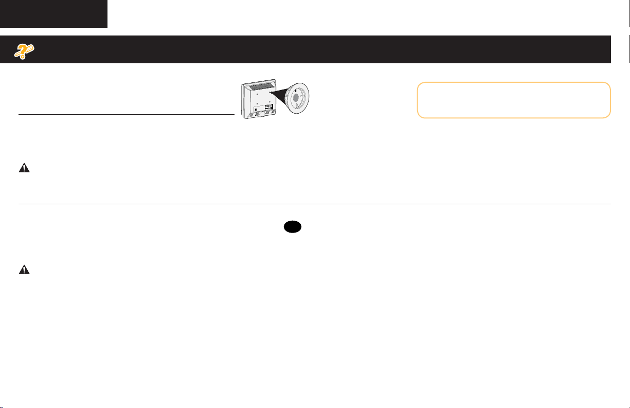
ESPAÑOL
Solución de problemas
Para televisores que incluyen separadores insertados
o aros adaptadores para soportes murales.
los separadores
proporcionados con
el televisor
a. Use los separadores proporcionados con el televisor, si el dorso del televisor es plano (Y usted quiere que su TV más cerca de la pared).
PRECAUCIÓN: Verifique el enrosque adecuado del tornillo o del conjunto tornillo/separador.
– Si es demasiado corto, no sostendrá el televisor. – Si es demasiado largo, dañará el televisor.
b. Use los separadores proporcionados con el televisor y los separadores Sanus
• televisores con dorso irregular o redondeado • dejar un espacio adicional para cables
PRECAUCIÓN: Verifique el enrosque adecuado del tornillo o del conjunto tornillo/separador.
– Si es demasiado corto, no sostendrá el televisor. – Si es demasiado largo, dañará el televisor.
09
para:
Si tiene dudas sobre la elección de los elementos de
fijación, contáctese con el servicio de atención al
cliente. 1-800-359-5520 (Reino Unido: 0800-056-2853)
Ver página 26
40
Page 41

ESPAÑOL
Descripción
La placa de sujeción se expande para adecuarse a televisores con patrones de orificios de 200 x 200 mm hasta 400 x 400 mm.
Los mecanismos de bloqueo brindan una mayor seguridad.
El ajuste del nivel crea una instalación sencilla.
Las placas de sujeción pueden ajustarse de un lado al otro de la placa mural para lograr un posicionamiento óptimo.
Los pies de apoyo sostienen el televisor para crear espacio para conectar los cables
Dimensiones
Ver página 27
Ver página 28
41
Page 42

Milestone AV Technologies and its a liated corporations and subsidiaries (collectively, “Milestone”), intend to make this manual accurate and complete. However,
Milestone makes no claim that the information contained herein covers all details, conditions, or variations. Nor does it provide for every possible contingency in
connection with the installation or use of this product. The information contained in this document is subject to change without notice or obligation of any kind.
Milestone makes no representation of warranty, expressed or implied, regarding the information contained herein. Milestone assumes no responsibility for accuracy,
completeness or su ciency of the information contained in this document.
Milestone AV Technologies y sus empresas asociadas y filiales (colectivamente “Milestone”) tienen la intención de que este manual sea preciso y completo. Sin embargo,
Milestone no garantiza que la información que contiene incluya todos los detalles condiciones y variaciones, ni que contemple toda posible contingencia en conexión con la
instalación y uso de este producto. La información contenida en este documento es susceptible de ser modificada sin aviso ni obligación de ningún tipo. Milestone no hace ninguna
manifestación de garantía, explícita o implícita, respecto a la información contenida este documento. Milestone no asume ninguna responsabilidad por la exactitud, integridad o
suficiencia de la información contenida en este documento.
42
Page 43

FOLLOW
SANUS
ON YOUR FAVORITE SOCIAL NETWORKS!
FACEBOOK.COM/SANUSSYSTEMS
TWITTER.COM/SANUSSYSTEMS
YOUTUBE.COM/SANUSSYSTEMS
Learn ways to get the most out of your space.
Find product updates and more.
Learn installation tips, tricks and household know-hows.
View step-by-step product videos to ease your install experiences.
Find the latest news stories about your favorite SANUS products.
Page 44

REGISTER YOUR NEW
By registering, you'll be entered to win, and will receive
By registering, you'll be entered to win, and will receive
the latest product updates, design tips, and other
the latest product updates, design tips, and other
ways to enhance your life in your home.
ways to enhance your life in your home.
1
1
Visit SANUS.com/register to complete your registration
Visit SANUS.com/register to complete your registration
and start enjoying all of the benefits SANUS has to oer.
and start enjoying all of the benefits SANUS has to oer.
2
2
Leave a product review and
Leave a product review and
let us know how your install went!
let us know how your install went!
3
3
If you ever have questions about your SANUS product, give us a call at 1-800-359-5520. We're ready to help!
If you ever have questions about your SANUS product, give us a call at 1-800-359-5520. We're ready to help!
‘Monthly prize’ rules and restrictions apply. Visit SANUS.com for more info.
‘Monthly prize’ rules and restrictions apply. Visit SANUS.com for more info.
800-359-5520 (UK: 0800-056-2853) • [email protected] • sanus.com
SANUS
PRODUCT!
All other brand names or marks are used for identification purposes and are trademarks of their respective owners.
©2015 Milestone AV Technologies. All rights reserved. SANUS is a division of Milestone.
SANUS • 6436 City West Parkway • Eden Prairie, MN 55344 USA
6901-002508 00
 Loading...