

Assembly Instructions for Model: VMFL1
Thank you for choosing a Sanus Systems Vision Mount wall mount. The VMFL1 is designed to mount up to 30” [76.2 cm] LCD at panel
televisions weighing up to 40 lbs [18 Kg] to a vertical wall. It will allow the television to be just 0.5” [12.7 mm] from the wall.
WARNING: If you do not understand these directions, or have any doubts about the safety of the installation, please call a qualied
contractor or contact Sanus at 800.359.5520 or www.sanus.com. Check carefully to make sure that there are no missing or defective
parts. Our customer service representatives can quickly assist you with installation questions and missing or damaged parts. Replacement
parts for products purchased through authorized dealers will be shipped directly to you. Never use defective parts. Improper installation
may cause damage or serious injury. Do not use this product for any purpose that is not explicitly specied by Sanus Systems. Sanus
Systems can not be liable for damage or injury caused by incorrect mounting, incorrect assembly, or incorrect use. Please call Sanus
Systems before returning products to the point of purchase.
Required Tools: 3/8 or 1/8 drill bit, phillips screwdriver
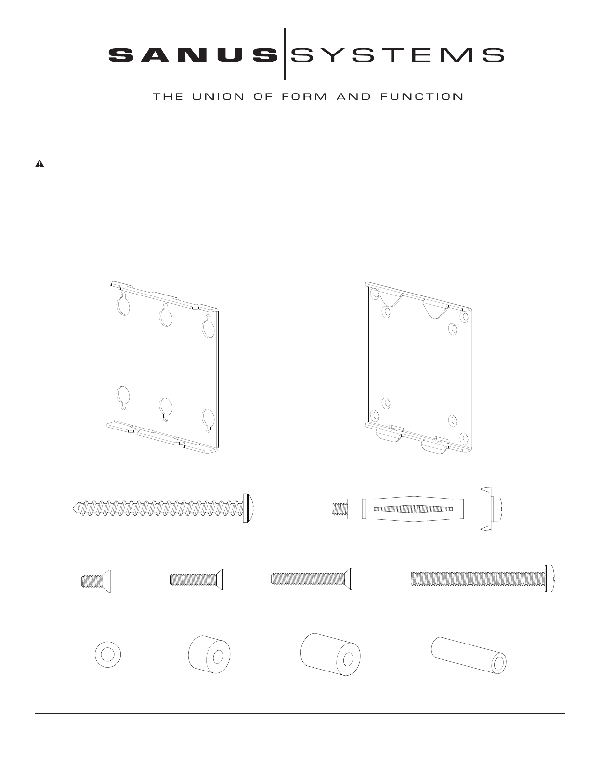
Supplied Parts and Hardware: (All threaded fasteners are shown full size.)
M4 x 10 mm Bolt - E
Qty. 4
M4 Washer - I
Qty. 4
Sanus Systems 2221 Hwy 36 West, Saint Paul, MN 55113 02.23.06 (000026)
Customer Service: 800.359.5520. See complementary Sanus products at www.sanus.com
Wall Plate - A
Qty. 1
Lag Screw - C
Qty. 2
M4 x 20 mm Bolt - F
Qty. 4
Small M4 Spacer - J
Qty. 4
M4 x 30 mm Bolt - G
Qty. 4
Large M4 Spacer - K
Qty. 4
Monitor Bracket - B
Qty. 1
Dry Wall Anchor - D
Qty. 4
M5 Locking Bolt - H
Qty. 2
M5 Spacer - L
Qty. 2
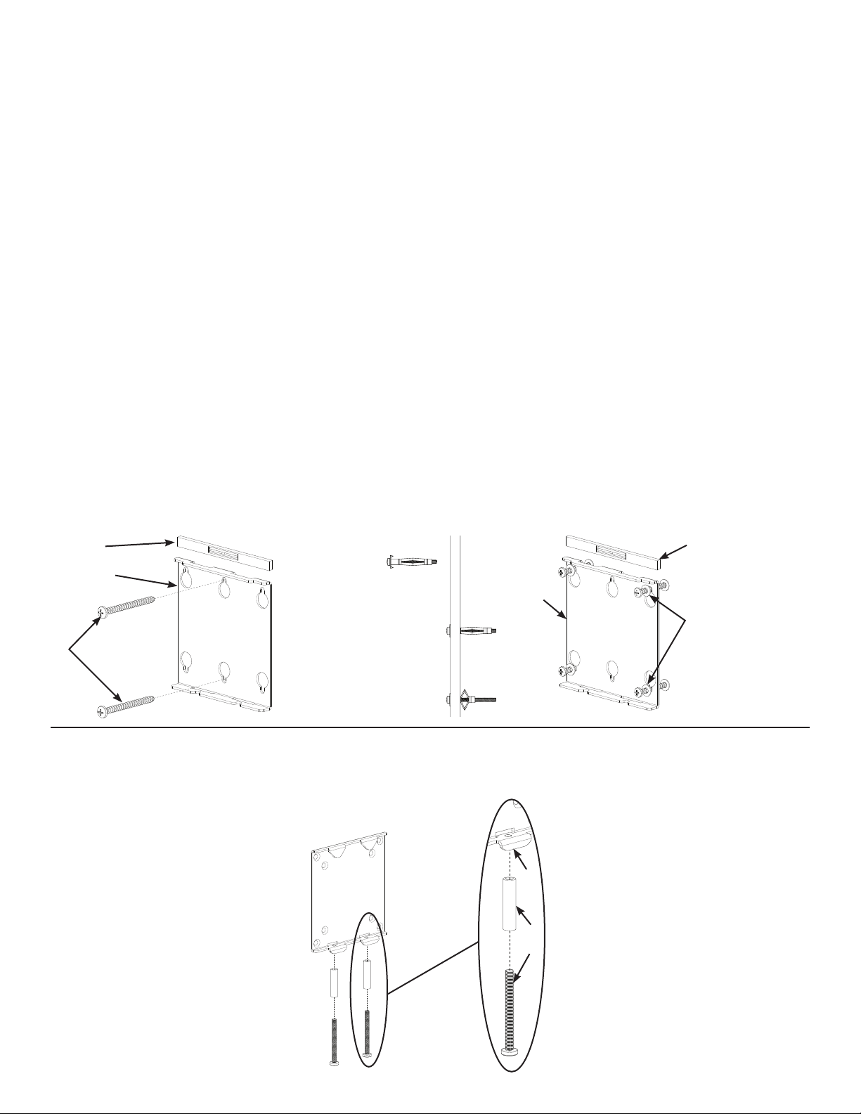
Step 1: Hang Wall Plate
NOTE: Make sure the Wall Plate (A) is oriented so the at surface in the center of the plate is against the wall as shown in
Diagram 1A.
Wood Stud Mounting:
Using a high quality stud sensor to locate a stud: then, using the Wall Plate (A) as a template mark two holes in the appropriate location,
making sure the hole is in the center area of the stud.
Pre-drill a 1/8” hole 2.5” [63.5 mm] deep where the upper Lag Screw (C) will be installed; then, secure the Wall Plate (A) to the stud using
one of the Lag Bolts as shown in Diagram 1A.
Verify that the Wall Plate is level; then pre-drill a 1/8” hole 2.5” [63.5 mm] deep for the lower Lag Screw (C) and secure the bottom of the
Wall Plate (A) with the second Lag Screw as shown in diagram 1A.
Drywall Installation:
Position the Wall Plate (A) in the desired location on the wall; then, use the Wall Plate as a template and mark the location of the four
outer mounting holes.
Using a 3/8” drill bit, proceed to drill a 3/8” pilot hole in each marked location.
Install a Dry Wall Anchor (D) in one of the pilot holes and tighten the Anchor Bolt until it is fully seated as shown in Diagram 1B.
NOTE: Make sure the Washer is between the head of the Anchor Bolt and the Wall Plate (A) as shown in Diagram 1C.
Loosen the Anchor Bolt approximately 1/4” and repeat the above process for the three additional pilot holes. Once Wall Plate (A) is
mounted onto the wall, verify that it is level; then, proceed to tighten all four Anchor Bolts.
Diagram 1A Diagram 1B Diagram 1C
Level
A
Insert
Dry Wall
C
Step 2: Install M5 Locking Bolts
Insert both M5 Locking Bolts (H) through a M5 Spacer (L); then, thread the M5 Locking Bolts into the Monitor Bracket (B) just enough to
engage the threads as shown in Diagram 2.
Diagram 2
Anchor (D)
Tighten Bolt
Until Anchor
is against wall
Drill 3/8”
Pilot Hole
A
B
Level
Washer must
be between
Anchor Bolt
and
Wall Plate (A)
L
H

Step 3: Attach Monitor Bracket to at back TV
To attach the Monitor Bracket (B) to the TV, insert a M4 x 10 mm Bolt (E) through the countersunk hole in the Monitor Bracket, and the
M4 Washer (I); then, thread it into the TV. Repeat this until all four bolts are secured to the TV, as shown in Diagram 3. Tighten each
M4 x 10 mm Bolt with a phillips screw driver.
Diagram 3
I
Step 4: Attach Monitor Bracket to a TV with a recessed hole pattern
To attach the Monitor Bracket (B) to the TV, insert a M4 x 20 mm Bolt (F) through the countersunk hole in the Monitor Bracket, and the
Small M4 Spacer (J); then, thread it into the TV. Repeat this until all four bolts are secured to the TV as shown in Diagram 4. Tighten each
M4 x 20 mm Bolt with a phillips screw driver.
Diagram 4
J
B
B
E
F
Step 5: Attach Monitor Bracket to a TV with a deeply recessed hole pattern
To attach the Monitor Bracket (B) to the TV, insert a M4 x 30 mm Bolt (G) through the countersunk hole in the Monitor Bracket, and the
Large M4 Spacer (K); then, thread it into the TV. Repeat this until all four bolts are secured to the TV as shown in Diagram 5. Tighten each
M4 x 30 mm Bolt with a phillips screw driver.
Diagram 5
K
B
G

Step 6: Attach Monitor Bracket to Wall Plate
Lift the TV so the two hooks on the Monitor Bracket (B) align with the slots on the top of the Wall Plate (A) as shown in Diagram 6A.
Lower the TV so that the hooks on the top of the Monitor Bracket (B) drop into the slots on the Wall Plate (A) but the hooks on the bottom
are not engaged as shown in Diagram 6B.
Diagram 6A Diagram 6B
B
A
Step 7: Cable hook up and lock Monitor Bracket to Wall Plate
To allow for greater space between the wall and your display to install cables, allow the display to hang from the two top hooks on the
Monitor Bracket (B) with the bottom tabs free to move as shown in Diagram 7A.
Once all cables are installed, lift the TV just enough to engage the two lower hooks on the Monitor Bracket (B) with the slots in the Wall
Plate (A) as shown in detail 7B
Tighten both M5 Locking Bolts (H) to secure the Monitor Bracket (B) to the Wall Plate (A).
Diagram 7A Diagram 7B
B
A
A
B
B
Sanus Systems 2221 Hwy 36 West, Saint Paul, MN 55113 02.23.06 (000026)
Customer Service: 800.359.5520. See complementary Sanus products at www.sanus.com
A
H
 Loading...