

GET IT
RIGHT
THE FIRST TIME
VMF
VMF
INSTRUCTION MANUAL
720-B2
720-S2
Follow this step-by-step
instruction manual to
speed up your installation.
AUS: +61 (0) 7 3299 7000
Texto en español, página 26 Deutscher Text Seiten 34 Svensk text sida 42
中文文字说明请参见第 50 页
Texte français page 30 Nederlandse tekst op pagina 38
WE’RE HERE TO HELP
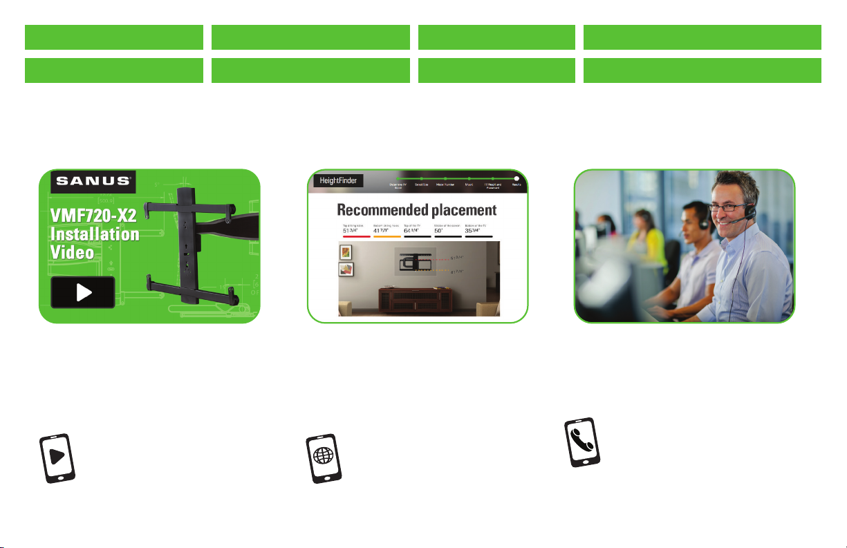
Want to watch a video that
shows how easy this DIY
project will be?
Watch it now at:
SANUS.com/2792
Get it right the first time.
HeightFinder™ shows you
where to drill.
Check it out at:
SANUS.com/2567
Русский текст: стр. 46
日本語は 54 ページ
Our install experts are
standing by to help.
Call us at:
US: 800-359-5520
EMEA: +31 (0) 495 580 852
UK: 0800 056 2853
2
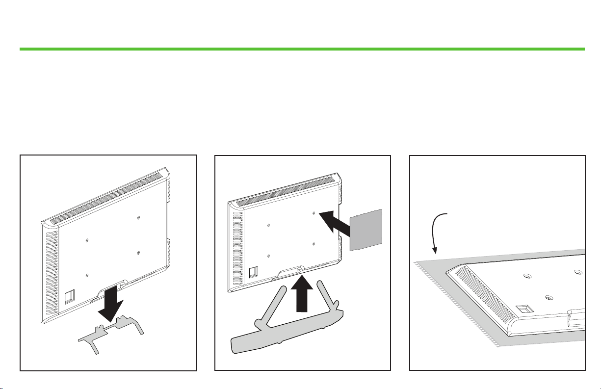
Before you begin
Remove the stand from your TV
— if attached.
Install any accessories
you may have purchased — if they
require the TV to be removed from the
wall for assembly. The TV is removable
for future accessory purchases.
Protect the face of your TV
when laying it down for installation.
Soft clean surface
3
IMPORTANT SAFETY INSTRUCTIONS – PLEASE READ MANUAL PRIOR TO USE – SAVE THESE INSTRUCTIONS
Please read through these instructions completely to be sure you’re comfortable with this easy install process.
Check your TV owner’s manual to see if there are any special requirements for mounting your TV.
If you do not understand these instructions or have doubts about the safety of the installation, assembly or use of this product,
contact Customer Service: [US]: 800-359-5520 [EMEA]: +31 (0) 495 580 852 [UK]: 0800 056 2853 [AUS]: +61 (0) 7 3299 7000.
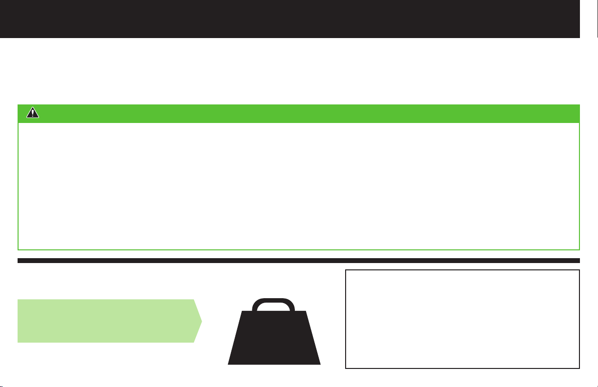
CAUTION: Avoid potential personal injuries and property damage!
● This product is designed ONLY to be installed into wood studs, solid concrete or concrete block.
— DO NOT INSTALL INTO DRYWALL ALONE — DRYWALL ALONE WILL NOT HOLD THE WEIGHT OF YOUR TV.
● This product is designed for INDOOR USE ONLY.
● The wall must be capable of supporting five times the weight of the TV and mount combined.
● Do not use this product for any purpose not explicitly specified by manufacturer.
● Manufacturer is not responsible for damage or injury caused by incorrect assembly or use.
If your TV (including accessories) exceeds
TV Weight Limit
this weight, this mount is NOT compatible.
(including accessories)
DO NOT EXCEED
4
55 lbs.
(24.9 kg)
Visit SANUS.com or call customer service to
find a compatible mount.
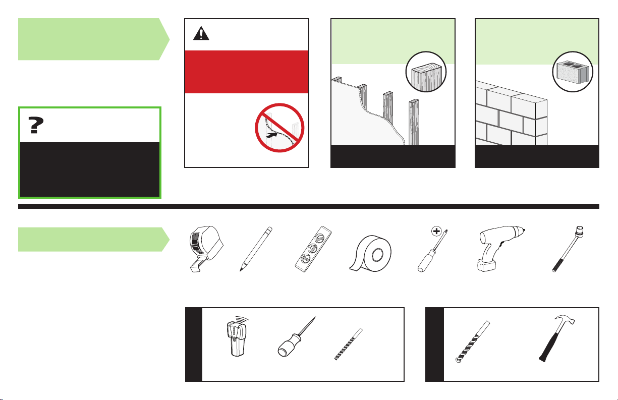
Wall
Construction
ONLY install on
these acceptable
wall types.
Call
Unsure
[US]: 800-359-5520
[EMEA]: +31 (0) 495 580 852
[UK]: 0800 056 2853
[AUS]: +61 (0) 7 3299 7000
Customer
Service
Tools Needed
CAUTION:
DO NOT install
in drywall alone
Drywall alone
will NOT hold
the weight of
your TV.
wood studs Solid concrete or
concrete block
ACCEPTABLE ACCEPTABLE
7/16 in.
(11 mm)
Measure
Wood Stud Install
Pencil Level Tape
Stud
Finder
Awl
1/8 in.
(3 mm)
Wood
Drill Bit
ScrewdriverTape
(10 mm)
Concrete
Concrete Install
Drill Bit
Electric
Drill
3/8 in.
Socket
Wrench
Hammer
5
M8 x 35mm
M8 x 16mm
M5 x 10mm
M6 x 12mm M6 x 35mm
M8 x 50mm
22mm
2.5mm
5mm
M8 x 25mm
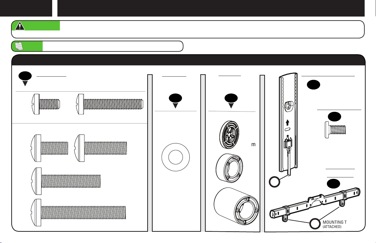
Attach TV Bracket to TVSTEP 1
WARNING: This product contains small items that could be a choking hazard if swallowed. Before starting assembly, verify all parts are included
and undamaged. If any parts are missing or damaged, do not return the damaged item to your dealer; contact Customer Service. Never use damaged parts!
NOTE: Not all hardware included will be used.
STEP 1 Parts and Hardware
M6
TV Screws
01
(qty. 4 each) [Only one size fits your TV]
Washers
(qty. 4 each)
Spacers
[If necessary]
(qty. 4 each)
0302
TV Bracket Vertical
(qty. 1)
04
Interface Screw
M6/M8
M8
6
M6/M8
R
RELEASE CORD
(ATTACHED)
MOUNTING TABS
M
(ATTACHED)
(qty. 4)
05
TV Bracket
Horizontal
(qty. 2)
06
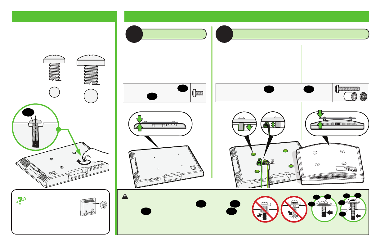
1.2 Select TV Screw Length and Spacers1.1 Select TV Screw Diameter
Only one screw size fits your TV.
M6
01
If your TV included
inset spacers or wall
mount adapters, see
Troubleshooting on PAGE 25.
M8
NO SPACER
A B
• Flat Back TV
[TV brackets
lay flat on your TV]
SPACER NEEDED
• Flat Back TV with
Extra Space Needed
[for deep inset holes
or cable interference]
Use short TV screws
Spacers
not needed.
03
01
.
Use long TV screws 01 and spacers
create extra space between the TV and TV bracket.
Inset Holes Cables Rounded Back
CAUTION: Verify adequate thread
engagement with your screw 01, washer 02,
spacer 03 combination AND TV bracket 06.
— Too short will not hold your TV.
— Too long will damage your TV.
• Rounded or
Irregular Back TV
[TV brackets NOT
resting flat on your TV]
03
to
01
02
06
Too Short Too Long Correct
06
03
01
02
7

W
1.3 Attach TV Brackets to Your TV
MEASURE
1
W
H
mm
mm
W
H
inches cm mm
4 10 100
7 ⅞ 20 200
11 ¾ 30 300
15 ¾ 40 400
inch dimensions are approximate
ADJUST TO WIDTH W
2
M
M
06
300 mm position illustrated
8
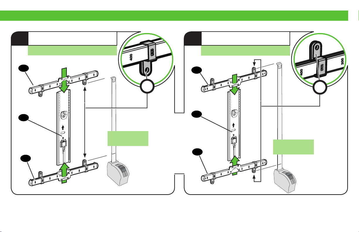
ASSEMBLE FOR HEIGHT H
3a
For height 200 mm or less
ASSEMBLE FOR HEIGHT H
3b
For height greater than 200 mm
06
04
06
≤ 200 mm
M
06
04
06
M
> 200 mm
9

1.3 (continued)
LOOSELY ASSEMBLE
4
06
06
NO SPACER SPACER NEEDED
A B
01
02
03
4X
02
01
5
CENTER
04
06
10
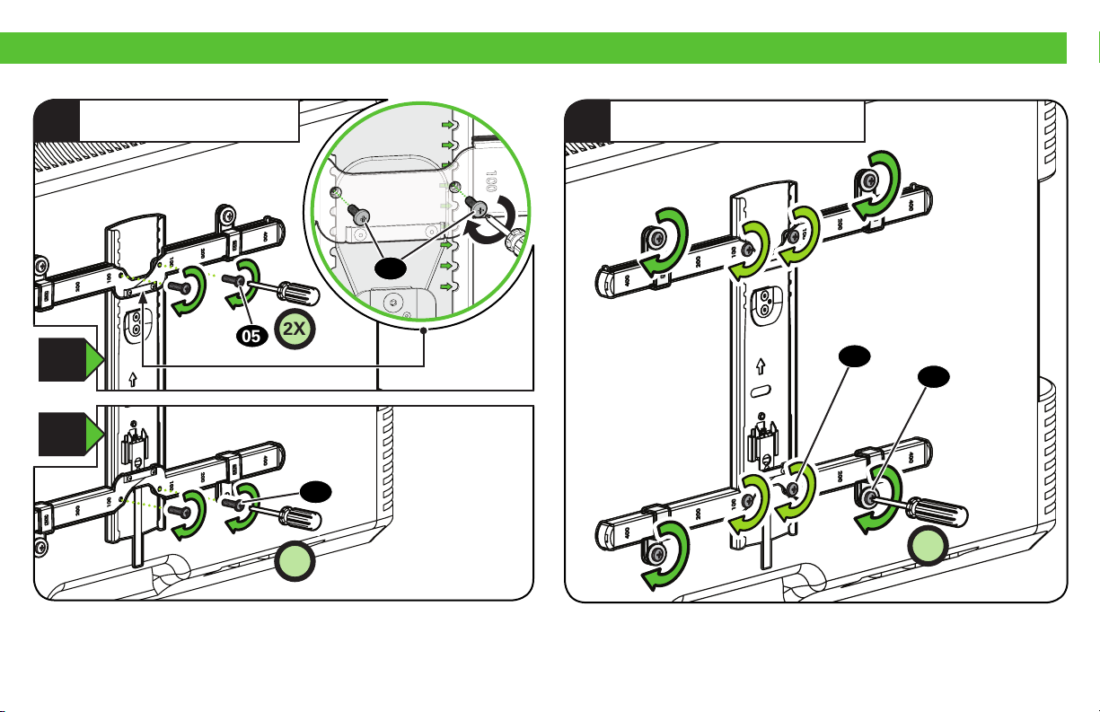
SECURE ASSEMBLY
6
a
b
05
2X
05
05
TIGHTEN ALL SCREWS
7
05
01
2X
8X
11
STEP 2
WARNING: This product contains small items that could be a choking hazard if swallowed. Before starting assembly, verify all parts are
included and undamaged. If any parts are missing or damaged, do not return the damaged item to your dealer; contact Customer Service.
Never use damaged parts!
NOTE: Not all hardware included will be used.
Attach Wall Plate to Wall
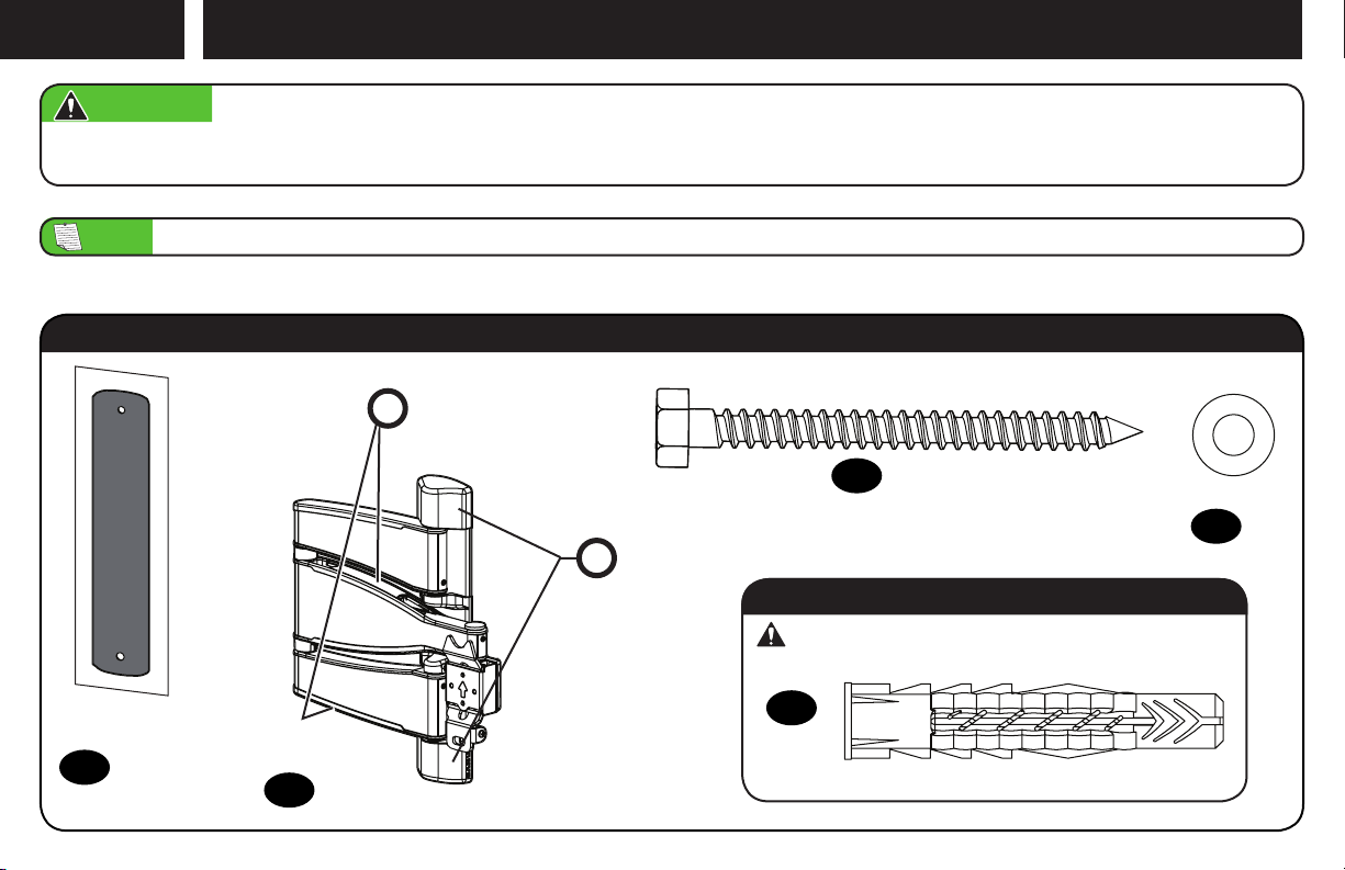
Parts and Hardware for STEP 2
12
Wall Plate
Template
x1
07
Arm Assembly
x1
08
C
CABLE COVERS
(ATTACHED)
WALL PLATE
COVER
(ATTACHED)
P
x2
Lag Bolt
1/4 x 2¾ in.
0
For concrete installations ONLY
CAUTION: Do not use in drywall or wood
09
x2
Concrete Anchor
11
x2
Fischer UX10 x 60R
Washer
1/4 in.
x2
10

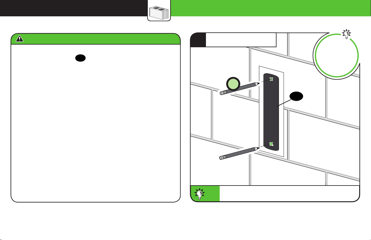
STEP 2A Attach Wall Plate Wood Stud Installation
CAUTION: Avoid potential
personal injury or property damage!
● Drywall covering the wall
must not exceed 5/8 in. (1.5 cm)
● Minimum wood stud size:
nominal 2 x 4 in. (5.1 x 10.2 cm)
actual 1 ½ x 3 ½ in. (3.8 x 8.9 cm)
● Stud center must be verified
Max. 5/8 in. (1.5 cm)
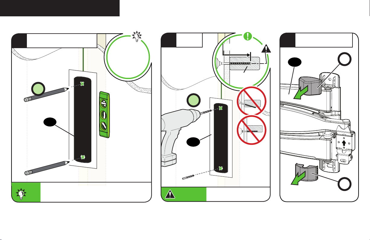
LOCATE
1
Min. 1 ½ in. (3.8 cm)
2
VERIFY
Min. 3 ½ in. (8.9 cm)
3
MARK
13
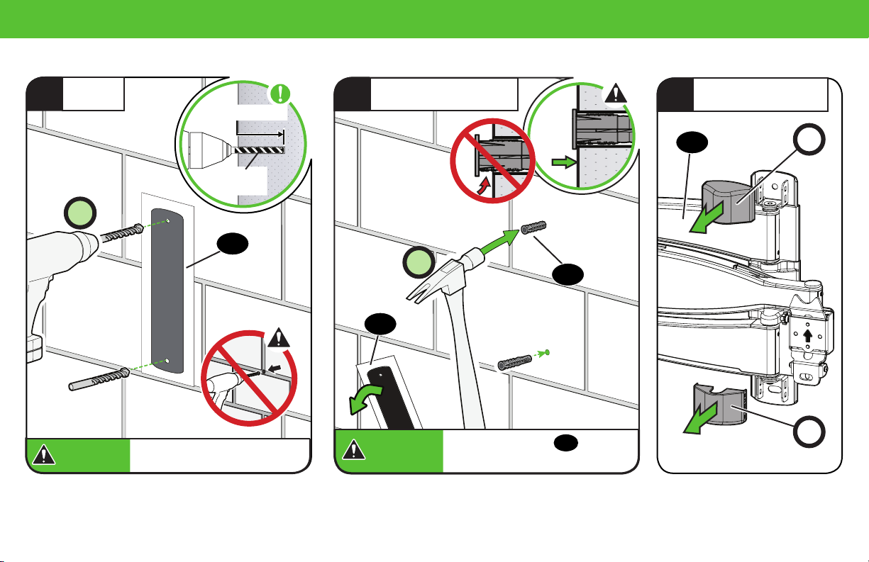
STEP 2A (continued)
POSITION TEMPLATE
4
2X
07
To calculate your precise wall plate location,
check out our HeightFinder at sanus.com
TIP:
[www.sanus.com/2567].
Visit
HeightFinder™
sanus.com
/2567
DRILL
5
CAUTION:
2X
07
2 ¾ in. (7.0 cm)
1/8 in.
(3 mm)
Be sure you drill into the
CENTER of the stud.
REMOVE COVERS
6
08
P
P
14
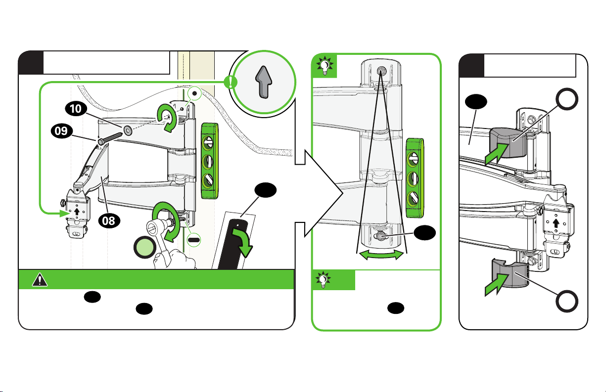
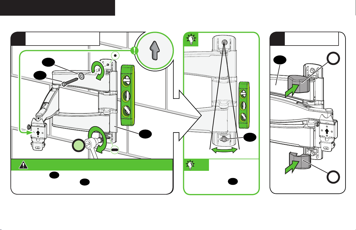
SECURELY TIGHTEN
7
INSERT COVERS
8
10
09
07
08
2X
CAUTION: Avoid potential personal injury or property damage!
Both lag bolts
movement of arm assembly
fastened to the wall before continuing on to the next step.
MUST BE firmly tightened to prevent unwanted
09
08
Ensure the wall plate is securely
.
09
TIP: You can make small
level adjustments by loosening
the bottom lag bolt 09 and
shifting the wall plate until level.
08
Go to STEP 3 on PAGE 19.
P
P
15
STEP 2B Attach Wall Plate
Solid Concrete or Concrete Block Installation
CAUTION: Avoid potential personal injury or property damage!
● Mount the wall plate
● Minimum solid concrete thickness: 8 in. (20.3 cm)
● Minimum concrete block size: 8 x 8 x 16 in. (20.3 x 20.3 x 40.6 cm)
directly onto the concrete surface
08
POSITION TEMPLATE
1
2X
To calculate your precise wall plate location, check out
TIP:
TIP:
our HeightFinder at sanus.com [www.sanus.com/2567].
Visit
HeightFinder™
sanus.com
/2567
07
16
2
DRILL
3 in. (7.5 cm)
INSERT ANCHORS
3
3
REMOVE COVERS
4
2X
CAUTION:
CAUTION:
3/8 in.
(10 mm)
07
Never drill into the mortar
between blocks.
2X
07
CAUTION:
CAUTION:
11
14
Be sure the anchors
flush with the concrete surface.
11
are seated
08
P
P
17
STEP 2B (continued)
SECURELY TIGHTEN
5
10
09
08
2X
CAUTION: Avoid potential personal injury or property damage!
Both lag bolts
movement of arm assembly
fastened to the wall before continuing on to the next step.
MUST BE firmly tightened to prevent unwanted
09
08
Ensure the wall plate is securely
.
09
TIP: You can make small
level adjustments by loosening
the bottom lag bolt 09 and
shifting the wall plate until level.
INSERT COVERS
6
08
P
P
18

STEP 3
Attach TV to Wall Plate
WARNING: Before starting assembly, verify this part is
undamaged. If damaged, do not return the damaged item to your dealer;
contact Customer Service. Never use damaged parts!
Parts and Hardware for STEP 3
Hex Key
Hex Key
5/32 in.
Securement
Screw
3/32 in.
13
14
x1
x1
10-32 x 1/4 in.
12
x1
HANG YOUR TV
1
HEAVY! You may
need assistance
with this step.
04
08
19

STEP 3 (continued)
ATTACH
2
SECURELY TIGHTEN
3
12
04
20
08
04
CAUTION: Avoid potential personal injury or property damage!
Always make sure your securement screw
the TV is securely fastened to the arm assembly 08.
08
14
is tightened, so
12

Manage Cables
ROUTE CABLES
1
C
08
C
IMPORTANT:
Pull arm
and prevent stretching the cables when the arms are moved.
08
to its full extension, to leave enough slack
ATTACH COVERS
2
C
08
C
21

Adjustments
LEVEL ADJUSTMENT TILT ADJUSTMENT
1 2 3
14
L
TILT
T
14
14
12
CAUTION:
12
MUST
Screw
be loosened before
turning screw
22
12
CAUTION:
injury or property damage!
Always make sure your securement screw
is tightened, so the TV is securely
12
.
L
fastened to the arm assembly
Avoid potential personal
08
.
Your TV should adjust easily when moved, then stay in place.
Adjust the tilt tension knobs
NOTE:
If you do not intend to adjust the tilt for different viewing locations,
you can tighten the tilt tension knobs
movement. If needed, use hex key
if your TV naturally tilts up or down.
T
, to prevent unwanted
T
14
to tighten more firmly.

13
EXTEND / RETRACT -- ONLY IF NECESSARY
E
13
E
E
13
TIP:
CAUTION:
ONLY If needed, adjust the arm tension when you extend or retract your TV, with screw
Avoid potential personal injury or property damage! DO NOT remove screws E, only turn enough for slight adjustment.
using hex key
E
13
.
23

REMOVE THE TV
HEAVY! You may need assistance with this step.
1. Disconnect all cables from the TV.
2. Remove securement screw
3. Pull down on the release cord
4. Carefully lift the TV from arm assembly 08.
12
.
to release the TV.
R
1 32
24
14
12
4
04
04
08
R

Troubleshooting
TV SUPPLIED SPACERS
Use your TV supplied spacer for:
A B
• Flat Back TV [TV bracket s lay flat on your TV]
NOTE:
M8 screws can be used without the washer for extra thread engagement.
FLAT BACK
a
• Flat Back TV with Extra Space Needed
ROUND BACK CABLES
If you are uncertain about your hardware selection,
contact Customer Service
Use your TV supplied spacer and spacer 03 for:
• Rounded or Irregular Back TV
[for deep inset holes or cable interference]
NOTE:
M8 screws can be used without the washer for extra thread engagement.
[TV bracket s NOT resting flat on your TV]
b
TV Supplied
Spacer
CAUTION: Avoid potential injury or property damage!
Use the correct screw length for adequate thread engagment.
Correct
– Too short will
not hold the TV.
– Too long will
damage the TV.
Too Short
Too Long
TV Supplied
Spacer
03
CAUTION: Avoid potential injury or property damage!
Use the correct screw length for adequate thread engagment.
Correct
– Too short will
not hold the TV.
– Too long will
damage the TV.
Too Short
Too Long
25

ESPAÑOL
INSTRUCCIONES IMPORTANTES DE SEGURIDAD: GUARDE ESTAS INSTRUCCIONES Y LEA TODO EL MANUAL ANTES DE UTILIZAR ESTE PRODUCTO.
Antes de empezar, asegúrese de que este es el soporte adecuado para usted.
¿Su televisor pesa
1
(accesorios incluidos)
MÁS de 24.9 kg
(55 lbs)?
¿De qué está
2
hecha la pared?
24,9 kg
(55 lbs)
No — ¡Perfecto!
Sí — Este soporte NO es compatible. Visite MountFinder.Sanus.com o llame al : [US]: 800-359-5520
[EMEA]: +31 (0) 495 580 852 [UK]: 0800 056 2853 [AUS]: +61 (0) 7 3299 7000 para encontrar un soporte compatible.
¿Paneles de yeso
con montantes
demadera?
¿Hormigón macizo o
bloques de hormigón?
¿No está seguro?
PRECAUCIÓN:
NO instalar en
paredes de yeso solo
¡Perfecto! ¡Perfecto!
¿Tiene todas las
3
herramientas
necesarias?
¿Preparado para
4
empezar?
Lápiz Nivel DestornilladorCinta métrica Taladro eléctrico Llave de tubo
Lea atentamente estas instrucciones para asegurarse de que está familiarizado con el sencillo proceso de instalación.
Consulte igualmente el manual de su televisor para conocer si existen requisitos especiales para el montaje de su aparato.
Si no entiende las instrucciones o si tiene dudas acerca de la seguridad de la instalación, el montaje o el uso del producto, póngase en
contacto con el servicio de atención al cliente o llame a nuestro servicio técnico.
11 mm
(7/16 pulg.)
Localizador de
Instalación sobre
montantes
montante de madera
Punzón
PRECAUCIÓN: Evite posibles lesiones personales y daños materiales.
● Este producto se ha diseñado para usarse en montantes de madera, hormigón macizo y paredes de bloques de hormigón:
NOloinstale en paredes únicamente de yeso
● La pared debe ser capaz de soportar hasta cinco veces el peso combinado del televisor y el soporte
● No utilice este producto para ningún otro propósito que no sea el especificado explícitamente por el fabricante
● El fabricante no se responsabiliza de ningún daño o lesión resultante del montaje incorrecto o el uso indebido del producto
ESTAMOS A SU DISPOSICIÓN PARA AYUDARLE
¿Desea ver un vídeo que muestra lo fácil que será este proyecto de bricolaje? Puede verlo en: SANUS.com/2592
Acierte a la primera. HeightFinder™ indica el lugar donde debe taladrar. Descúbralo en: SANUS.com/2567
Nuestros expertos instaladores en EE. UU. están a su disposición para ayudarle. Llámenos al:
26
US]: 800-359-5520 [EMEA]: +31 (0) 495 580 852
[UK]: 0800 056 2853 [AUS]: +61 (0) 7 3299 7000
Llame al servicio de atención al cliente:
[US]: 800-359-5520 [EMEA]: +31 (0) 495 580 852
[UK]: 0800 056 2853 [AUS]: +61 (0) 7 3299 7000
3 mm
(1/8 pulg.)
Broca para
madera Martillo
10 mm
(3/8 pulg.)
hormigón
Broca para
Instalación sobre
hormigón

Antes de comenzar
ESPAÑOL
Retire el soporte de su televisor... ¡si ya estaba instalado, claro!
Instale cualquier accesorio que quiera añadir a su televisor.
Consulte todos los manuales de instalación de los accesorios para determinar si necesita INSTALARLOS ANTES de montar su televisor.
Proteja la pantalla de su televisor cuando lo tumbe para la instalación.
Cómo acoplar el soporte al televisorPASO 1
ADVERTENCIA: Este producto contiene piezas pequeñas que, en caso de ser tragadas, podrían causar asfixia. Antes de comenzar a montar la unidad, verifique que dispone de todas las piezas yque se encuentran en
buen estado. Si no dispone de todas las piezas o alguna está dañada, no devuelva el elemento defectuoso al distribuidor. Póngase en contacto con el servicio de atención al cliente. Nunca utilice piezas en mal estado.
NOTA: No se utilizarán todos los elementos de sujeción incluidos.
1.1 Seleccione el diámetro de los tornillos del televisor
Solo se adapta a su televisor un tamaño de tornillo.
1.2 Seleccione la longitud de los tornillos y los espaciadores del televisor
SIN ESPACIADOR
A
• Televisor con parte posterior plana [los soportes del televisor se apoyan planos sobre su televisor]
Utilice tornillos de televisor cortos
ESPACIADOR NECESARIO
B
No es necesario usar
01
.
03
espaciadores.
• Televisor con parte posterior plana que necesita espacio extra [para agujeros profundos o interferencia de cables]
• Televisor con parte posterior redondeada o irregular [los soportes de televisor NO se apoyan completamente planos en su televisor]
Use tornillos de televisor
largos y espaciadores
01
para crear espacio extra entre el televisor y el soporte del televisor.
03
1.3 Monte el soporte del televisor
MEDIR
1
AJUSTAR A LA ANCHURA W
2
MONTAR PARA LA ALTURA H
3a
MONTAR PARA LA ALTURA H
3b
MONTAR SIN APRETAR
4
CENTRAR
5
FIJAR EL MONTAJE
6
APRETAR TODOS LOS TORNILLOS
7
Para una altura de 200 mm o menos
Para una altura superior a 200 mm
Cómo fijar la placa a la paredPASO 2
ADVERTENCIA: Este producto contiene piezas pequeñas que, en caso de ser tragadas, podrían causar asfixia. Antes de comenzar a montar la unidad, verifique que dispone de todas las piezas y
que se encuentran en buen estado. Si no dispone de todas las piezas o alguna está dañada, no devuelva el elemento defectuoso al distribuidor. Póngase en contacto con el servicio de atención al cliente.
Nunca utilice piezas en mal estado.
NOTA: No se utilizarán todos los elementos de sujeción incluidos.
PÁGINA 6
PÁGINA 11
27

ESPAÑOL
1
LOCALIZAR
2
VERIFICAR
3
MARCAR
4
COLOCAR LA PLANTILLA
5
TALADRAR
6
RETIRAR LAS CUBIERTAS
7
APRETAR FIRMEMENTE
8
INSERTAR LAS CUBIERTAS
Vaya al PASO 3 en la PÁGINA 19.
PASO 2A
PRECAUCIÓN: Evite posibles lesiones personales o daños materiales.
Los paneles de yeso que cubren la pared no deben superar los 1,5 cm (5/8 pulg.) • Tamaño mínimo de los montantes de madera: nominal 5,1 x 10,2 cm (2 x 4 pulg.), real 3,8 x 8,9
•
cm (1½ x 3½ pulg.). • Debe comprobar el centro del montante
Colocación sobre montantes de madera
CONSEJO: Para calcular la ubicación precisa de su placa mural, descubra nuestro Height Finder en sanus.com [www.san.us/2567].
P
PRECAUCIÓN: Evite posibles lesiones personales o daños materiales. Los cuatro pernos tirafondo
movimientos no deseados de la placa mural 08.
P
09
DEBEN ESTAR apretados con firmeza para evitar
PÁGINA 12
PASO 2B
PRECAUCIÓN: Evite posibles lesiones personales o daños materiales.
Monte la placa mural 08 directamente sobre la superficie de hormigón • Grosor mínimo del hormigón macizo: 20,3 cm (8 pulg.) • Tamaño mínimo del bloque de hormigón: 20,3 x 20,3 x 40,6 cm (8 x 8 x 16 pulg.)
•
1
COLOCAR LA PLANTILLA
2
TALADRAR
3
INSERTAR ANCLAJES
4
RETIRAR LAS CUBIERTAS
5
APRETAR FIRMEMENTE
PRECAUCIÓN: Evite posibles lesiones personales o daños materiales. Los cuatro pernos tirafondo
6
INSERTAR LAS CUBIERTAS
PRECAUCIÓN: Nunca taladre sobre el cemento entre los bloques.
Instalación en hormigón macizo o bloque de hormigón
CONSEJO: Para calcular la ubicación precisa de su placa mural, descubra nuestro Height Finder en sanus.com [www.san.us/2567].
PRECAUCIÓN: Asegúrese de que los anclajes
P
P
11
estén asentados al mismo nivel que la superficie de hormigón.
DEBEN ESTAR apretados con firmeza para evitar movimientos no deseados de la placamural 08.
09
Cómo fijar el televisor a la placa muralPASO 3
ADVERTENCIA: Antes de comenzar a montar la unidad, verifique que todas las piezas estén en buen estado. Si alguna está dañada, no devuelva el elemento defectuoso al distribuidor.
Póngase en contacto con el servicio de atención al cliente. Nunca utilice piezas en mal estado.
1
COLGAR ¡ELEMENTO PESADO! Podría necesitar ayuda para realizar esta operación.
2
FIJAR
3
APRETAR FIRMEMENTE
PRECAUCIÓN: Evite posibles lesiones personales o daños materiales. Asegúrese siempre de que el tornillo de bloqueo
28
esté bien apretado, para que el televisor quede fijado de forma seguraalconjunto del brazo 08.
12
PÁGINA 15
PÁGINA 18

ESPAÑOL
Gestión de los cables
1
PASE LOS CABLES
2
VUELVA A COLOCAR LA CUBIERTA
IMPORTANTE: xtienda el brazo
08
por completo antes de pasar los cables.
Ajustes
NIVELACIÓN
PRECAUCIÓN:
PRECAUCIÓN: Evite posibles lesiones personales o daños materiales. Asegúrese siempre de que el tornillo de bloqueo
INCLINACIÓN
Su televisor debería ajustarse fácilmente al moverlo y luego mantenerse en su posición. Ajuste la perilla de tensión de inclinación T si su televisor se inclina por sí solo hacia arriba o hacia abajo.
NOTA: Si no tiene intención de ajustar la inclinación para ver el televisor desde diferentes ángulos, puede apretar las perillas de tensión de inclinación a mano T para evitar movimientos indeseados.
Sies necesario, utilice una llave hexagonal para apretar las perillas T.
Se DEBE aflojar el tornillo 12 antes de girar el tornillo L.
esté bien apretado, para que el televisor quede fijado de forma seguraalconjunto del brazo 08.
12
EXTENSIÓN/RETRACCIÓN -- SOLO SI ES NECESARIO
PRECAUCIÓN: NO retire los tornillos
RETIRADA DEL TELEVISOR
1. Desconecte todos los cables del televisor. 2. Retirada el tornillo de bloqueo
, solo gírelos lo suficiente para realizar pequeños ajustes.
E
¡ELEMENTO PESADO! Podría necesitar ayuda para realizar esta operación.
. 3. Tire hacia abajo del anillo de liberación
12
R
para extraer el televisor. 4. Levante con cuidado el televisor para separarlo del conjunto del brazo 08.
Resolución de problemas
a: Use el espaciador suministrado con el televisor si este tiene la parte posterior plana (Y desea que quede más pegado a la pared).
b: Use el espaciador suministrado con el televisor y el espaciador
Si no está seguro de su selección de piezas, póngase en contacto con el servicio de atención al cliente
PRECAUCIÓN: Evite posibles lesiones personales y daños materiales.
Dimensiones
03
para: Televisores con dorsos redondeados (irregulares) o Cuando necesita espacio adicional para los cables.
.
Use la longitud de tornillo adecuada para un enrosque seguro. Si es demasiado corto, no sujetará el televisor. Si es demasiado largo, dañará el aparato.
PÁGINA 23
PÁGINA 24
PÁGINA 28
PÁGINA 29
29

FRANÇAIS
Avant de commencer, assurons-nous que ce support vous convient parfaitement!
Votre téléviseur
1
(accessoires compris)
pèse-t-il PLUS de
24,9 kg (55 lb)?
De quoi est fait
2
le mur?
INFORMATIONS IMPORTANTES CONCERNANT LA SÉCURITÉ – CONSERVEZ CES INSTRUCTIONS –
VEUILLEZ LIRE ATTENTIVEMENT LE MANUEL AVANT D'UTILISER CE PRODUIT
Non — Parfait !
24,9 kg
(55 lb)
Oui — Ce support n'est PAS compatible. Visitez le site MountFinder.Sanus.com ou appelez le
[US]: 800-359-5520 [EMEA]: +31 (0) 495 580 852 [UK]: 0800 056 2853 [AUS]: +61 (0) 7 3299 7000
pour trouver un support compatible.
Cloison sèche à
montants en bois ?
Béton plein ou
bloc de béton ?
Vous avez des
doutes?
ATTENTION:
NE l'installez PAS seul
sur une cloison sèche
Parfait! Parfait!
Contactez le service à la clientèle :
[US]: 800-359-5520 [EMEA]: +31 (0) 495 580 852
[UK]: 0800 056 2853 [AUS]: +61 (0) 7 3299 7000
Avez-vous
3
tous les outils
requis?
Vous êtes prêt à
4
commencer?
11 mm
(7/16 po)
Ruban
à mesurer
Veuillez lire intégralement ces instructions afin que vous soyez à l'aise avec ce processus d'installation facile. Veuillez également
consulter le manuel du fabricant de votre téléviseur pour savoir si son installation présente des exigences particulières.
Si vous ne comprenez pas toutes ces instructions ou si vous avez des doutes sur la sécurité concernant l'installation, le montage ou
l'utilisation dece produit, veuillez contacter le service clientèle.
Crayon Niveau Tournevis
Perceuse
électrique
Clé à
douilles
Localisateur de
montants en bois
montants
Installation sur des
Alêne
3 mm
(1/8 po)
Foret à
bois
du béton
Installation sur
10 mm
(3/8 po)
Foret pour
béton
ATTENTION: Évitez les risques de blessures corporelles ou de dommages matériels!
● Ce produit est conçu pour une utilisation sur des montants en bois, des murs en béton plein et en bloc de béton - NE l'installez
PAS seul sur une cloison sèche.
● Le mur doit pouvoir supporter cinq fois le poids total du téléviseur et du support.
● N'utilisez pas ce produit à d'autres fins que celles spécifiées par le fabricant.
● Le fabricant n'est pas responsable des blessures ou des dommages causés par une mauvaise utilisation ou un montage incorrect.
NOUS SOMMES LÀ POUR VOUS AIDER
Souhaitez-vous voir une vidéo démontrant à quel point cette procédure est facile à eectuer ? Rendez-vous maintenant sur : SANUS.com/2592
Réussissez du premier coup ! HeightFinder™ vous indique à quel endroit percer. Renseignez-vous à l'adresse : SANUS.com/2567
Nos experts de l'installation basés aux États-Unis sont là pour vous aider. Appelez-nous au:
30
US]: 800-359-5520 [EMEA]: +31 (0) 495 580 852
[UK]: 0800 056 2853 [AUS]: +61 (0) 7 3299 7000
Marteau

Avant de commencer
FRANÇAIS
Retirez le socle de votre téléviseur ... s'il est installé bien sûr.
Installez tout accessoire que vous prévoyez d'ajouter à votre téléviseur.
Vérifiez les manuels d'installation de tous les accessoires pour savoir si vous devez les INSTALLER AVANT de monter votre téléviseur.
Protégez la face de votre téléviseur lorsque vous la poserez vers le bas pour l'installation.
Fixation de la patte de fixation au téléviseurÉTAPE 1
AVERTISSEMENT : Ce produit contient de petites pièces qui peuvent représenter un risque d'étouffement si elles sont avalées. Avant de commencer l'assemblage, assurez-vous qu'il ne manque aucune pièce et qu'elles ne sont
pas endommagées. Si une pièce est manquante ou endommagée, contactez le service à la clientèle et non le détaillant. N'utilisez jamais de pièces endommagées!
REMARQUE: Les pièces fournies ne doivent pas nécessairement être toutes utilisées.
1.1 Sélectionnez le diamètre des vis pour le téléviseur
Votre téléviseur ne prend en charge qu’une seule taille de vis.
1.2 Sélectionnez la longueur des vis et les entretoises pour le téléviseur
SANS ENTRETOISE
A
• Téléviseur au dos plat [Les pattes de fixation du téléviseur sont posées à plat sur votre téléviseur]
Utilisez des vis de téléviseurs courtes
ENTRETOISE REQUISE
B
• Téléviseur au dos plat nécessitant plus d’espace [pour les trous d’insertions profonds ou l’enchevêtrement des câbles]
• Téléviseur au dos irrégulier ou arrondi [Les pattes de fixation du téléviseur NE reposent PAS à plat sur votre téléviseur]
Utilisez des vis de téléviseur longues 01 et des entretoises
1.3 Assemblage de la patte de fixation pour téléviseur
MESUREZ
1
RÉGLEZ EN FONCTION DE LA LARGEUR W
2
ASSEMBLEZ RELATIVEMENT À LA HAUTEUR H
3a
ASSEMBLEZ RELATIVEMENT À LA HAUTEUR H
3b
ASSEMBLAGE LÂCHE
4
CENTREZ
5
ASSEMBLAGE SOLIDE
6
SERREZ TOUTES LES VIS
7
ÉTAPE 2
AVERTISSEMENT : Ce produit contient de petites pièces qui peuvent représenter un risque d'étouffement si elles sont avalées. Avant de commencer l'assemblage, assurez-vous qu'il ne manque aucune
pièce et qu'elles ne sont pas endommagées. Si une pièce est manquante ou endommagée, contactez le service à la clientèle et non le détaillant. N'utilisez jamais de pièces endommagées!
REMARQUE: Les pièces fournies ne doivent pas nécessairement être toutes utilisées.
Les entretoises
01
.
ne sont pas nécessaires.
03
pour laisser plus d’espace entre le téléviseur et sa patte de fixation.
03
Relativement à une hauteur de 200mm ou moins
Relativement à une hauteur supérieure à 200mm
Fixation de la plaque murale au mur
PAGE 6
PAGE 11
31

FRANÇAIS
1
LOCALISEZ
2
VÉRIFIEZ
3
MARQUEZ
4
POSITIONNEZ LE GABARIT
5
PERCEZ
6
RETIREZ LES CACHES
7
SERREZ CORRECTEMENT
ATTENTION : Évitez les risques de blessures corporelles ou de dommages matériels! Les quatre boulons tire-fond 09 DOIVENT ÊTRE serrés fermement afin d'éviter tout mouvement non souhaité
de la plaque murale 08.
8
INSÉREZ LES CACHES
Passez à l'ÉTAPE3, PAGE19.
ÉTAPE 2B
ATTENTION : Évitez les risques de blessures corporelles ou de dommages matériels!
Montez la plaque murale 08 directement sur la surface de béton. • Épaisseur minimale du béton solide: 20,3 cm (8 po) • Dimension minimale du bloc de béton: 20,3 x 20,3 x 40,6 cm (8 x 8 x 16 po)
•
1
POSITIONNEZ LE GABARIT
2
PERCEZ
3
INSÉREZ LES CHEVILLES
4
RETIREZ LES CACHES
5
SERREZ CORRECTEMENT
ATTENTION : Évitez les risques de blessures corporelles ou de dommages matériels! Les quatre boulons tire-fond
souhaité de la plaque murale 08.
6
INSÉREZ LES CACHES
ÉTAPE 2A
ATTENTION : Évitez les risques de blessures corporelles ou de dommages matériels! • L'épaisseur du revêtement de cloison sèche ne doit pas excéder 1,5 cm (5/8po).
Taille minimum des montants en bois: nominale 5,1 x 10,2 cm (2 x 4 po), réelle 3,8 x 8,9 cm (1 ½ x 3 ½ po). • Les centres des montants doivent être vérifiés.
Installation sur des montants en bois
CONSEIL: Pour calculer l'emplacement précis de la plaque murale, renseignez-vous sur notre HeightFinder sur le site sanus.com [www.san.us/2567].
P
P
Installation sur du béton plein ou des blocs de béton
ATTENTION : Prenez soin de ne jamais percer dans le mortier entre les blocs.
P
CONSEIL: Pour calculer l'emplacement précis de la plaque murale, renseignez-vous sur notre HeightFinder sur le site sanus.com [www.san.us/2567].
ATTENTION : Assurez-vous que les chevilles
P
11
ne dépassent pas de la surface de béton.
09
DOIVENT ÊTRE serrés fermement afin d'éviter tout mouvement non
ÉTAPE 3 Fixation du téléviseur sur la plaque murale
AVERTISSEMENT : Avant de commencer l'assemblage, assurez-vous que cette pièce est en bon état. Si elle est endommagée, ne la retournez pas à votre détaillant. Contactez plutôt le service à la
clientèle. N'utilisez jamais de pièces endommagées!
1
ACCROCHEZ LOURD ! Vous aurez besoin de quelqu'un pour vous aider à cette étape.
2
FIXEZ
3
SERREZ CORRECTEMENT
ATTENTION : Évitez les risques de blessures corporelles ou de dommages matériels! Veillez toujours à ce que la vis de blocage
12
soit serrée, afin que le téléviseur soit correctement fixé au bras 08.
PAGE 12
•
PAGE 15
PAGE 18
32

FRANÇAIS
Gestion des câbles
IMPORTANT:
Retirez le cache-câble C du bras 08 Faites passer le câble le long du bras. Replacez le cache-câble C .
Allongez complètement le bras 08 pour laisser suffisamment de jeu et éviter que les câbles soient étirés lorsque les bras sont déplacés.
Réglages
NIVEAU
ATTENTION : La vis
ATTENTION : Évitez les risques de blessures corporelles ou de dommages matériels! Veillez toujours à ce que la vis de blocage
INCLINAISON
Votre téléviseur doit se régler facilement lorsqu'il est déplacé, puis il doit rester bien en place. Réglez les boutons de tension de l'inclinaison T si votre téléviseur s'incline naturellement vers le haut
ou le bas. REMARQUE: Si vous ne prévoyez pas de régler l'inclinaison pour différents angles de vue, vous pouvez serrer manuellement les boutons de tension de l'inclinaison T afin d'éviter tout
mouvement non souhaité. Si besoin, utilisez une clé hexagonale pour serrer les boutons T.
EXTENSION / RÉTRACTION - SEULEMENT SI NÉCESSAIRE
ATTENTION: NE retirez PAS les vis
RETRAIT DU TÉLÉVISEUR
1. Débranchez tous les câbles du téléviseur. 2. Retrait la vis de blocage
Dépannage
DOIT être desserée avant de tourner la vis L.
12
, tournez-les simplement suffisamment pour un léger ajustement.
E
LOURD ! Vous aurez besoin de quelqu'un pour vous aider à cette étape.
12
. 3. Tirez la bague de dégagement vers le bas
12
soit serrée, afin que le téléviseur soit correctement fixé au bras 08.
R
pour libérer le téléviseur. 4. Soulevez doucement le téléviseur à partir du bras 08.
PAGE 23
PAGE 24
PAGE 28
a: Utilisez l'entretoise destinée aux téléviseurs à dos plat fournie avec le téléviseur (ET vous devez faire en sorte que votre téléviseur soit le plus près du mur).
b: Utilisez l'entretoise fournie avec le téléviseur et l'entretoise
Si vous avez des doutes sur votre sélection de matériel, contactez le service clientèle
ATTENTION : Évitez les risques de blessures corporelles ou de dommages matériels!
court, le téléviseur ne tiendra pas et s'il est trop long, le téléviseur sera endommagé.
Dimensions
03
pour : des téléviseurs à dos rond ou de forme irrégulière ou pour ajouter de l'espace nécessaire pour les câbles.
.
Utilisez une longueur de vis correcte afin d'assurer un bon engagement dans le filetage. Si l'engagement est trop
PAGE 29
33

DEUTSCH
WICHTIGE SICHERHEITSHINWEISE – BEWAHREN SIE DIESE HINWEISE SORGFÄLTIG AUF – LESEN SIE VOR DEM GEBRAUCH
DES PRODUKTS BITTE DAS GESAMTE HANDBUCH
Stellen Sie vor Montagebeginn sicher, dass diese Halterung für Sie geeignet ist!
Wiegt Ihr Fernseher
1
(einschließlich Zubehör)
MEHR als 24,9 kg (55
lbs.)?
Woraus besteht
2
Ihre Wand?
VORSICHT:
NICHT an reine
Gipskartonwand anbringen
Haben Sie alle
3
erforderlichen
Werkzeuge?
Startklar?
4
24,9kg
(55lbs.)
Perfekt! Perfekt!
Bitte lesen Sie sich diese einfachen Montageanleitungen vollständig durch.
Sehen Sie auch im Handbuch Ihres Fernsehers nach, ob für die Montage Ihres Fernsehers spezielle Anforderungen gelten.
Falls Sie diese Anleitungen nicht verstehen oder Zweifel an der Sicherheit der Montage, des Zusammenbaus oder der Verwendung
dieses Produkts haben, wenden Sie sich an den Kundendienst.
Nein – Perfekt!
Ja – Diese Halterung ist NICHT kompatibel. Besuchen Sie MountFinder.Sanus.com oder rufen Sie die Nummer
[US]: 800-359-5520 [EMEA]: +31 (0) 495 580 852 [UK]: 0800 056 2853 [AUS]: +61 (0) 7 3299 7000
an, um eine kompatible Halterung zu finden.
Gipskarton mit
Holzbalken?
Stift Wasserwaage SchraubendreherMaßband Elektrobohrer
11mm
(7/16")
Steckschlüssel
Massivbeton oder
Betonblöcke?
Montage
anHolzbalken
Kundendienst anrufen:
[US]: 800-359-5520 [EMEA]: +31 (0) 495 580 852
[UK]: 0800 056 2853 [AUS]: +61 (0) 7 3299 7000
3 mm
(1/8")
AhleBalkensucher
Bohreinsatz
für Holz
VORSICHT: Vermeiden Sie Verletzungen und Sachschäden!
● Dieses Produkt ist für die Montage an Wänden mit Holzträgern oder an Massivbeton- und Betonblockwänden bestimmt. NICHT
an einer reinen Gipskartonwand montieren
● Die Wand muss das Fünache des Gesamtgewichts des Fernsehers und der Halterung tragen können
● Verwenden Sie dieses Produkt nur für die vom Hersteller ausdrücklich angegebenen Zwecke
● Der Hersteller haftet nicht für Schäden oder Verletzungen, die durch unsachgemäße Montage, unsachgemäßen Zusammenbau
oder unsachgemäße Verwendung verursacht wurden
WIR SIND FÜR SIE DA
Möchten Sie sich ein Video ansehen, das zeigt, wie einfach dieses Heimwerkerprojekt ist? Schauen Sie rein auf: SANUS.com/2592
Machen Sie es gleich richtig. HeightFinder™ zeigt Ihnen, wo Sie bohren müssen. Sehen Sie es sich an auf: SANUS.com/2567
Unsere Montageexperten in den USA stehen zu Ihrer Verfügung. Rufen Sie uns an:
34
US]: 800-359-5520 [EMEA]: +31 (0) 495 580 852
[UK]: 0800 056 2853 [AUS]: +61 (0) 7 3299 7000
Nicht sicher?
10 mm
(3/8")
Bohreinsatz
Montage an Beton
für Beton
Hammer

Vorbereitung
DEUTSCH
Nehmen Sie Ihren Fernseher vom Standfuß ... natürlich nur, falls Sie einen verwenden.
Montieren Sie alles Zubehör, das Sie mit dem Fernseher benutzen wollen.
Sehen Sie in den Installationshandbüchern des Zubehörs nach, ob Sie es VOR dem Aufhängen des Fernsehers MONTIEREN müssen.
Schützen Sie die Bildschirmseite Ihres Fernsehers, wenn Sie ihn für die Montage hinlegen.
Befestigen der TV-Anschlussplatte am FernseherSCHRITT 1
WARNUNG: Dieses Produkt enthält kleine Teile, die beim Verschlucken zum Erstickungstod führen können. Prüfen Sie vor Montagebeginn, ob alle Teile vorhanden und unbeschädigt sind. Falls Teile fehlen
oder beschädigt sind, bringen Sie das Produkt nicht zum Händler zurück, sondern wenden Sie sich an den Kundendienst. Verwenden Sie niemals beschädigte Teile!
HINWEIS: Es wird nicht das gesamte mitgelieferte Befestigungsmaterial verwendet.
1.1 Wählen Sie den Schraubendurchmesser für den Fernseher aus
Nur eine Schraubengröße passt für Ihren Fernseher.
1.2 Wählen Sie die Schraubenlänge und die Distanzscheiben für den Fernseher aus
KEINE DISTANZSCHEIBE
A
• Flachfernseher [TV-Halterungen flach auf Ihren Fernseher legen]
Verwenden Sie kurze Schrauben für den Fernseher
DISTANZSCHEIBEN ERFORDERLICH
B
• Flachfernsehermit Extra-Distanzscheibe erforderlich [für tiefe Einschublöcher oder störende Kabel]
• Gerundete oder unregelmäßige Rückseite des Fernsehers [Fernsehhalterungen liegen NICHT flach auf Ihrem Fernseher auf]
Verwenden Sie lange Schrauben 01 und Distanzscheiben für den Fernseher,
1.3 Montieren der Anschlussplatten für den Fernseher
MESSUNG
1
ANPASSEN AN DIE BREITE W
2
MONTAGE DER HÖHE H
3a
MONTAGE DER HÖHE H
3b
LOCKERE MONTAGE
4
ZENTRIEREN
5
SICHERE MONTAGE
6
ANZIEHEN ALLER SCHRAUBEN
7
SCHRITT 2
WARNUNG: Dieses Produkt enthält kleine Teile, die beim Verschlucken zum Erstickungstod führen können. Prüfen Sie vor Montagebeginn, ob alle Teile vorhanden und unbeschädigt sind. Falls Teile fehlen
oder beschädigt sind, bringen Sie das Produkt nicht zum Händler zurück, sondern wenden Sie sich an den Kundendienst. Verwenden Sie niemals beschädigte Teile!
HINWEIS: Es wird nicht das gesamte mitgelieferte Befestigungsmaterial verwendet.
Für eine Höhe von maximal 200mm
Für eine Höhe von mehr als 200mm
Anbringen der Wandplatte an der Wand
Distanzscheiben
01
.
nicht erforderlich
03
um mehr Abstand zwischen Fernseher und seiner Halterung zu schaffen.
03
SEITE 6
SEITE 11
35

DEUTSCH
SCHRITT 2A
1
LOKALISIEREN
2
ÜBERPRÜFEN
MARKIEREN
3
4
SCHABLONE ANSETZEN
5
BOHREN
ABDECKUNGEN ENTFERNEN
6
7
FEST ANZIEHEN
VORSICHT: Vermeiden Sie Verletzungen und Sachschäden! Alle vier Schlüsselschrauben
ABDECKUNGEN EINSETZEN
8
Gehen Sie zu SCHRITT3 auf SEITE19.
SCHRITT 2B
VORSICHT: Vermeiden Sie Verletzungen und Sachschäden!
Montieren Sie die Wandplatte 08 direkt an der Betonfläche • Mindestdicke der Massivbetonwand: 20,3 cm (8") • Mindestmaße des Betonblocks: 20,3 x 20,3 x 40,6 cm (8 x 8 x 16")
•
1
SCHABLONE ANSETZEN
2
BOHREN
3
DÜBEL EINSETZEN
ABDECKUNGEN ENTFERNEN
4
5
FEST ANZIEHEN
VORSICHT: Vermeiden Sie Verletzungen und Sachschäden! Alle vier Schlüsselschrauben 09 MÜSSEN fest angezogen werden, um ein ungewolltes Verrutschen der Wandplatte
ABDECKUNGEN EINSETZEN
6
VORSICHT: Bohren Sie niemals in den Mörtel zwischen Steinen.
VORSICHT: Vermeiden Sie Verletzungen und Sachschäden!
Nenngröße 5,1 x 10,2 cm (2 x 4"), tatsächlich 3,8 x 8,9 cm (1½ x 3½"). • Die Balkenmitte muss überprüft werden.
TIPP: Nutzen Sie unseren Height Finder auf salus.com [www.san.us/2567], um die genaue Befestigungsstelle für die Wandplatte zu berechnen.
P
P
Montage an Massivbeton oder Betonblöcken
TIPP: Nutzen Sie unseren Height Finder auf salus.com [www.san.us/2567], um die genaue Befestigungsstelle für die Wandplatte zu berechnen.
VORSICHT: Stellen Sie sicher, dass die Dübel 11 bündig mit der Betonoberfläche abschließen.
P
P
Montage an Holzbalken
Die Gipsschicht der Wand darf 1,5 cm (5/8") nicht überschreiten. • Mindestmaße der Holzbalken:
•
09
MÜSSEN fest angezogen werden, um ein ungewolltes Verrutschen der Wandplatte 15 zu verhindern.
SEITE 12
08
zu verhindern.
SEITE 15
Befestigen des Fernsehers an der WandplatteSCHRITT 3
WARNUNG: Prüfen Sie vor Montagebeginn, ob dieses Teil unbeschädigt ist. Falls das Teil beschädigt ist, bringen Sie es nicht zum Händler zurück, sondern wenden Sie sich bitte an den Kundendienst. Verwenden Sie niemals beschädigte Teile!
1
AUFHÄNGEN SCHWER! Bei diesem Schritt werden Sie eventuell Hilfe benötigen.
2
ANBRINGEN
3
FEST ANZIEHEN
VORSICHT: Vermeiden Sie mögliche Verletzungen und Sachschäden! Stellen Sie stets sicher, dass die Feststellschraube
36
12
fest angezogen ist, damit der Fernseher sicher am Auszieharm 08 befestigt ist.
SEITE 18

DEUTSCH
Kabelführung
WICHTIG: Ziehen Sie den Arm
Entfernen Sie die Kabelabdeckungen C vom Arm 08. Legen Sie die Kabel am Arm entlang. Bringen Sie die Kabelabdeckungen C wieder an.
08
bis zu seiner vollen Länge aus und lassen Sie so genug Spiel, um ein Überdehnen der Kabel beim Bewegen des Arms zu verhindern.
Einstellungen
SEITE 23
SEITE 24
AUSRICHTEN
VORSICHT: Die Schraube
VORSICHT: Vermeiden Sie mögliche Verletzungen und Sachschäden! Stellen Sie stets sicher, dass die Feststellschraube
NEIGEN
Der Fernseher sollte durch Bewegen leicht zu verstellen sein und dann in Position bleiben. Verstellen Sie die Neigungsspannung über die Knöpfe T, falls der Fernseher von alleine vor- oder zurückkippt. HINWEIS: Wenn Sie das Gerät
nicht für unterschiedliche Fernsehpositionen neigen wollen, können Sie die Knöpfe T mit der Hand gegen ungewollte Bewegung fest anziehen. Bei Bedarf können Sie den Sechskantinnenschlüssel verwenden, um die Knöpfe T anzuziehen
MUSS gelöst werden, bevor die Schraube L verstellt werden darf.
12
12
fest angezogen ist, damit der Fernseher sicher am Auszieharm 08 befestigt ist.
AUSZIEHEN/EINFAHREN -- NUR WENN NÖTIG
VORSICHT: Die Schrauben
ABNEHMEN DES FERNSEHERS
1. Entfernen Sie sämtliche Kabel vom Fernseher. 2.
Fehlerbehebung
NICHT HERAUSSCHRAUBEN, nur zum Einstellen ein wenig drehen.
E
SCHWER! Bei diesem Schritt werden Sie eventuell Hilfe benötigen.
Abnehmen die Feststellschraube
.
12
3. Ziehen Sie den Lösering R nach unten, um den Fernseher freizugeben. 4. Heben Sie den Fernseher
vorsichtig vom Auszieharm 08.
SEITE 28
a: Verwenden Sie die mit dem Fernseher mitgelieferten Abstandhalter für einen Flachbildfernseher (UND wenn Sie den Fernseher näher an der Wand befestigen wollen).
b: Benutzen Sie den mit dem Fernseher mitgelieferten Abstandhalter und den Abstandhalter
Wenn Sie sich bei der Wahl der Befestigungsmaterialien nicht sicher sind, kontaktieren Sie den Kundendienst.
VORSICHT: Vermeiden Sie Verletzungen und Sachschäden!
Schrauben beschädigen den Fernseher.
Abmessungen
Verwenden Sie die korrekte Schraubenlänge für die richtige Einschraubtiefe. Zu kurze Schrauben halten den Fernseher nicht und zu lange
03
: für Fernseher mit gewölbter (unregelmäßiger) Rückseite oder wenn zusätzlicher Platz für die Kabel benötigt wird.
SEITE 29
37

NEDERLANDS
BELANGRIJKE VEILIGHEIDSINSTRUCTIES – BEWAAR DEZE INSTRUCTIES – LEES DE VOLLEDIGE HANDLEIDING VOORAFGAAND AAN HET GEBRUIK
Controleer voor u begint of deze wandbevestiging ook voor u geschikt is!
Weegt uw tv
1
(inclusief accessoires)
MEER dan
24,9 kg (55 lbs.)?
Waar is de muur
2
van gemaakt?
LET OP:
NIET op alleen
gipsplaat monteren
Beschikt u over
3
al het benodigde
gereedschap?
Klaar om te
4
beginnen?
24,9 kg
(55 lbs.)
Perfect! Perfect!
Lees deze instructies volledig door om er zeker van te zijn dat u dit gemakkelijke installatieproces juist kunt uitvoeren.
Raadpleeg ook de handleiding van uw tv op speciale vereisten voor het bevestigen van de tv.
Als u deze instructies niet begrijpt of twijfelt over de veiligheid van de installatie, de montage of het gebruik van dit product,
neem dan contact op met de klantenservice.
LET OP: Voorkom lichamelijk letsel en materiële schade!
● Dit product is ontworpen voor gebruik in muren met houten constructie, muren van massief beton en muren van
cementblokken - NIETgebruiken voor alleen gipsplaten
● De wand moet geschikt zijn om vijf keer het gecombineerde gewicht van de tv en de montagesteun te ondersteunen
● Gebruik dit product niet voor doeleinden die niet expliciet zijn gespecificeerd door de fabrikant
● De fabrikant is niet verantwoordelijk voor schade of letsel als gevolg van onjuiste montage of verkeerd gebruik
Nee: Prima!
Ja: Deze wandbevestiging is NIET geschikt. Raadpleeg MountFinder.Sanus.com of bel
[US]: 800-359-5520 [EMEA]: +31 (0) 495 580 852 [UK]: 0800 056 2853 [AUS]: +61 (0) 7 3299 7000 o
m een geschikte wandbevestiging te vinden.
Gipsplaat met
houten dragers?
Potlood Waterpas SchroevendraaierRolmaat maat Boormachine
11 mm
(7/16 in.)
Dopsleutel
Massief beton of
betonblokken?
houten drager
Montage aan een
Bel de klantenservice:
[US]: 800-359-5520 [EMEA]: +31 (0) 495 580 852
[UK]: 0800 056 2853 [AUS]: +61 (0) 7 3299 7000
3 mm
(1/8 in.)
PriemBalkzoeker
Bit voor
boormachine (hout) Hamer
WIJ STAAN VOOR U KLAAR
Wilt u een video bekijken die u toont hoe gemakkelijk dit doe-het-zelf-project is? Bekijk het nu op: SANUS.com/2592
Doe het in een keer goed. HeightFinder™ laat u zien waar u moet boren. Bekijk het op: SANUS.com/2567
Onze installatie-experts in de VS staan klaar om u te helpen. Bel ons op:
38
US]: 800-359-5520 [EMEA]: +31 (0) 495 580 852
[UK]: 0800 056 2853 [AUS]: +61 (0) 7 3299 7000
Weet u het niet
zeker?
10 mm
(3/8 in.)
Bit voor
Montage op beton
boormachine (beton)

Voordat u begint
NEDERLANDS
Verwijder de standaard van uw tv (mits er een is geïnstalleerd natuurlijk).
Installeer eventuele accessoires op uw tv.
Lees alle installatiehandleidingen van de accessoires om te bepalen of u deze moet INSTALLEREN VOORDAT u de tv monteert.
Bescherm de voorkant van de tv wanneer u deze neerzet voor de installatie.
De tv-beugel aan de tv monterenSTAP 1
WAARSCHUWING: Dit product bevat kleine onderdelen die verstikkingsgevaar kunnen opleveren als ze worden ingeslikt. Controleer vóór de montage of alle onderdelen onbeschadigd aanwezig zijn.
Mochten er onderdelen ontbreken of beschadigd zijn, breng het beschadigde item dan niet terug naar de verkoper, maar neem contact op met de klantenservice. Gebruik nooit beschadigde onderdelen!
OPMERKING: Niet alle bijgeleverde materialen zullen worden gebruikt.
PAGINA 6
1.1 De schroeven voor de tv selecteren (dikte)
Slechts één schroefgrootte is geschikt voor uw tv.
1.2 De schroeflengte en afstandhouders voor de tv selecteren
GEEN AFSTANDHOUDER
A
• TV met vlakke achterkant [tv-beugels liggen plat op uw tv]
Gebruik korte tv-schroeven
AFSTANDHOUDER VEREIST
B
Afstandhouders
01
.
zijn niet vereist.
03
• Tv met een vlakke achterkant met extra benodigde ruimte vereist [voor diepe inzetgaten of kabelbelemmeringen]
• Tv met een ronde of onregelmatige achterkant [Tv-beugels liggen NIET plat op de tv]
Gebruik lange tv-schroeven 01 en afstandhouders
om extra ruimte tussen de tv en tv-beugel te creëren.
03
1.3 De tv-beugel monteren
METEN
1
DE BREEDTE AANPASSEN B
2
DE HOOGTE AANPASSEN H
3a
DE HOOGTE AANPASSEN H
3b
LOS MONTEREN
4
MIDDEN
5
VEILIG MONTEREN
6
ALLE SCHROEVEN VASTDRAAIEN
7
WAARSCHUWING: Dit product bevat kleine onderdelen die verstikkingsgevaar kunnen opleveren als ze worden ingeslikt. Controleer vóór de montage of alle onderdelen onbeschadigd aanwezig zijn. Mochten
er onderdelen ontbreken of beschadigd zijn, breng het beschadigde item dan niet terug naar de verkoper, maar neem contact op met de klantenservice. Gebruik nooit beschadigde onderdelen!
OPMERKING: Niet alle bijgeleverde materialen zullen worden gebruikt.
Voor een hoogte van maximaal 200 mm
Voor een hoogte van minimaal 200 mm
Wandplaat aan de wand bevestigenSTAP 2
PAGINA 11
39

NEDERLANDS
1
ZOEKEN
2
CONTROLEREN
3
MARKEREN
4
HET SJABLOON POSITIONEREN
5
BOREN
6
DE AFDEKKINGEN VERWIJDEREN
7
STEVIG AANDRAAIEN
LET OP: Voorkom lichamelijk letsel of materiële schade! Alle vier de schroeven
8
DE AFDEKKINGEN PLAATSEN
Ga naar STAP 3 op PAGINA 19.
STAP 2A
LET OP: Voorkom lichamelijk letsel of materiële schade!
Gipsplaten die de muur bedekken, mogen niet dikker zijn dan 1,5 cm (5/8 in.). • Minimale grootte houten drager: nominaal 5,1 x 10,2 cm (2 x 4 in.), werkelijk 3,8 x 8,9
•
cm (1½ x 3½ in.). • Het midden van de dragers moet worden gecontroleerd
TIP: Om de locatie van de wandplaat te bepalen, kunt u onze Height Finder bekijken op sanus.com [www.san.us/2567].
P
P
Installatie met houten dragers
09
MOETEN stevig worden aangedraaid om ongewenste beweging van de wandplaat te voorkomen 08.
PAGINA 12
STAP 2B
LET OP: Voorkom lichamelijk letsel of materiële schade!
Bevestig de wandplaat
•
1
HET SJABLOON POSITIONEREN
2
BOREN
3
DE ANKERS PLAATSEN
4
DE AFDEKKINGEN VERWIJDEREN
5
STEVIG AANDRAAIEN
LET OP: Voorkom lichamelijk letsel of materiële schade! Alle vier de schroeven
6
DE AFDEKKINGEN PLAATSEN
rechtstreeks op het betonnen oppervlak. • Minimale dikte massief beton: 20,3 cm (8 in.). • Minimale grootte betonblok: 20,3 x 20,3 x 40,6 cm (8 x 8 x 16 in.).
08
LET TOP: Boor nooit in het cement tussen blokken.
Montage aan massief beton of betonblokken
LET OP: Om de locatie van de wandplaat te bepalen, kunt u onze Height Finder bekijken op sanus.com [www.san.us/2567].
LET OP: Zorg ervoor dat de ankers
P
P
11
helemaal in het betonoppervlak worden geplaatst.
09
MOETEN stevig worden aangedraaid om ongewenste beweging van de wandplaat te voorkomen 08.
De tv aan de wandplaat bevestigenSTAP 3
WAARSCHUWING: Controleer voordat u met de montage begint of het onderdeel niet beschadigd is. Mochten er onderdelen beschadigd zijn, breng het beschadigde item dan niet terug naar de verkoper,
maar neem contact op met de klantenservice. Gebruik nooit beschadigde onderdelen!
1
OPHANGEN ZWAAR! Voor het uitvoeren van deze stap is mogelijk assistentie vereist.
2
BEVESTIGEN
3
STEVIG AANDRAAIEN
LET OP: Voorkom lichamelijk letsel of materiële schade! Zorg ervoor dat de vergrendelschroef
40
12
stevig is aangedraaid, zodat het armdeel stevig wordt bevestigd aan de wandplaat 08.
PAGINA 15
PAGINA 18

NEDERLANDS
Kabels verbergen
BELANGRIJK: Trek de arm
Verwijder de kabelafdekking C uit de arm 08. Leid de kabels langs de arm. Bevestig de kabelafdekkingen C.
08
volledig uit, maar laat voldoende speling en zorg ervoor dat de kabel niet worden uitgetrokken wanneer de armen worden bewogen.
Aanpassingen
RECHT HANGEN
LET OP: Schroef
LET OP: Voorkom lichamelijk letsel of materiële schade! Zorg ervoor dat de vergrendelschroef
MOET worden losgemaakt vooraleer aan de schroef L wordt gedraaid.
12
12
stevig is aangedraaid, zodat het armdeel stevig wordt bevestigd aan de wandplaat 08.
KANTELEN
Uw tv moet zich gemakkelijk aanpassen als u hem beweegt en vervolgens op zijn plek blijven zitten. Pas de kantelspanningsknoppen T aan als de tv uit zichzelf omhoog of omlaag beweegt.
OPMERKING: Als u de kijkhoek niet wilt aanpassen, kunt u de kantelspanningsknoppen T handmatig aandraaien om ongewenste bewegingen te voorkomen. Gebruik indien nodig de inbussleutel
om de knoppen T aan te draaien.
INTREKKEN / UITTREKKEN - ALLEEN INDIEN NODIG
LET OP: Verwijder de schroeven NIET
, draai ze alleen voldoende voor een kleine aanpassing.
E
DE TV VERWIJDEREN ZWAAR! Voor het uitvoeren van deze stap is mogelijk assistentie vereist.
1. Koppel alle kabels van de tv los. 2. Verwijder de vergrendelschroef
12
. 3. Druk de ontgrendelingsring omlaag
R
om de tv te ontgrendelen. 4. Til de tv voorzichtig van het armdeel af 08 .
Problemen oplossen
a: Gebruik de bij de tv geleverde afstandhouder voor tv's met een vlakke achterkant (EN als u de tv dichter bij de wand wilt hebben).
b: Gebruik de met de tv meegeleverde afstandhouder en afstandhouder
Als u twijfelt over uw materiaalkeuze, kunt u contact opnemen met de klantenservice
LET OP: Voorkom lichamelijk letsel of materiële schade!
schroef zal de tv beschadigen.
Afmetingen
03
voor: Tv's met een ronde achterkant of als er extra kabelruimte nodig is.
.
Gebruik de juiste schroeflengte zodat de schroef voldoende in de schroefdraad grijpt. Een te korte schroef zal de tv niet vasthouden en een te lange
PAGINA 23
PAGINA 24
PAGINA 28
PAGINA 29
41

SVENSKA
VIKTIGA SÄKERHETSANVISNINGAR – SPARA DESSA ANVISNINGAR – LÄS HELA BRUKSANVISNINGEN INNAN DU ANVÄNDER DENNA PRODUKT
Innan du börjar bör du se till att det här monteringsfästet är perfekt för dig!
Väger TV:n (inklusive
1
tillbehör)
MER än 24,9 kg
(55 lb)?
Vad är din vägg
2
gjord av?
24,9 kg
(55 lb)
Nej – Perfekt!
Ja – Det här monteringsfästet är INTE kompatibelt. Gå in på MountFinder.Sanus.com eller ring
[US]: 800-359-5520 [EMEA]: +31 (0) 495 580 852 [UK]: 0800 056 2853 [AUS]: +61 (0) 7 3299 7000
för att hitta ett kompatibelt monteringsfäste.
Gipsskiva med
träreglar?
Massiv betong eller
betongblock?
Osäker?
Ring kundtjänst:
[US]: 800-359-5520 [EMEA]: +31 (0) 495 580 852
[UK]: 0800 056 2853 [AUS]: +61 (0) 7 3299 7000
3 mm
(1/8 tum)
TräborrbitElborr Hammare
10 mm
(3/8 tum)
påbetong
Installering
Installera INTE på
endast gipsskiva
Har du alla
3
verktyg som
behövs?
Är du redo
4
att börja?
FÖRSIKTIGT:
Perfekt! Perfekt!
11 mm
(7/16 tum)
Hylsnyckel Betongborrbit
Läs igenom hela bruksanvisningen för att vara säker på att du är bekväm med denna enkla monteringsprocess.
Läs också i din TV:s bruksanvisning för att se om det finns några särskilda krav för montering av din TV.
Om du inte förstår dessa anvisningar eller är tveksam om installationen, monteringen eller användningen är säker bör du ringa
kundtjänst.
FÖRSIKTIGHET: Undvik personskada och skada på egendom!
● Den här produkten är utformad för att användas i träregelväggar, väggar av massiv betong och betongblocksväggar –
MONTERA INTE i enbart gipsvägg.
● Väggen måste kunna bära en vikt på upp till fem gånger TV och upphängning tillsammans.
● Använd inte denna produkt för andra ändamål än de som uttryckligen omnämns av tillverkaren.
● Tillverkaren kan inte hållas ansvarig för skador eller olycksfall som förorsakats av felaktig montering eller användning.
påträregel
Installering
PrylPenna Vattenpass RegelsökareSkruvmejselMåttband
VI ÄR HÄR FÖR ATT HJÄLPA DIG
Vill du titta på ett videoklipp som visar hur enkelt det här Gör-det-själv-projektet kommer att bli? Titta på klippet nu på: SANUS.com/2592
Gör rätt från början. HeightFinder™ visar var du borrar. Kolla in den på: SANUS.com/2567
Våra USA-baserade installationsexperter finns redo att hjälpa till. Ring oss på:
42
US]: 800-359-5520 [EMEA]: +31 (0) 495 580 852
[UK]: 0800 056 2853 [AUS]: +61 (0) 7 3299 7000

Innan du börjar
SVENSKA
Ta bort stativet från TV:n ... om det är installerat, självklart.
Installera eventuella tillbehör som du planerar att använda med TV:n.
Läs alla bruksanvisningar till tillbehör för att bestämma om du behöver INSTALLERA dem INNAN du monterar TV:n.
Skydda TV:ns framsida när du lägger den ner för installation.
Montera TV-fästet till TV:nSTEG 1
VARNING: Den här produkten innehåller små delar som kan utgöra kvävningsrisk om de sväljs. Innan du påbörjar hopmonteringen ska du kontrollera att alla delar finns med och är intakta. Om någon del
saknas eller är skadad ska du inte returnera den skadade produkten till din återförsäljare, utan vända dig direkt till kundtjänst. Använd aldrig skadade delar!
OBS! Inte alla monteringstillbehör som medföljer kommer att användas.
1.1 Välja skruvdiameter för TV:n
Endast en skruvstorlek passar TV:n.
1.2 Välja skruvlängd och distansbrickor för TV:n
INGEN DISTANSBRICKA
A
• Flatback-TV [TV-fästena ligger platt på TV:n]
Använd korta TV-skruvar
DISTANSBRICKA KRÄVS
B
Distansbrickor
01
.
03
ej nödvändigt.
• Flatback-TV med extra utrymmeskrav [för djupa hål eller kabelstörning]
• TV med rundad eller oregelbunden baksida [TV-fästena ligger INTE platt mot TV:n]
Använd långa TV-skruvar 01 och distansbrickor
för att skapa extra utrymme mellan TV:n och TV-fästet.
03
1.3 Montera TV-fästet
MÄT
1
JUSTERA BREDDEN B
2
MONTERA FÖR HÖJD H
3a
MONTERA FÖR HÖJD H
3b
LÖS MONTERING
4
CENTRERA
5
MONTERA FAST
6
DRA ÅT ALLA SKRUVAR
7
För en höjd på 200mm eller mindre
För höjder över 200mm
Montera väggplatta på väggSTEG 2
VARNING: Den här produkten innehåller små delar som kan utgöra kvävningsrisk om de sväljs. Innan du påbörjar hopmonteringen ska du kontrollera att alla delar finns med och är intakta. Om någon del
saknas eller är skadad ska du inte returnera den skadade produkten till din återförsäljare, utan vända dig direkt till kundtjänst. Använd aldrig skadade delar!
OBS! Inte alla monteringstillbehör som medföljer kommer att användas.
SIDAN 6
SIDAN 11
43

SVENSKA
STEG 2A
FÖRSIKTIGHET: Undvik eventuella personskador och materiella skador!
Gipsskiva som täcker väggen får inte överstiga 1,5 cm (5/8 tum). • Minsta storlek på träregel: nominell 5,1 x 10,2 cm (2 x 4 tum) eektiv 3,8 x 8,9 cm (1½ x 3½ tum).
1
HITTA
2
VERIFIERA
3
MARKERA
4
PLACERA MALL
5
BORRA
6
TA BORT SKYDDEN
7
DRA ÅT ORDENTLIGT
FÖRSIKTIGHET: Undvik eventuella personskador och materiella skador! Alla fyra fästskruvarna
8
SÄTT SKYDDEN PÅ PLATS
Gå till STEG 3 på SIDA 19.
STEG 2B
FÖRSIKTIGHET: Undvik eventuella personskador och materiella skador!
Montera väggplattan 08 direkt på betongytan. • Minimitjocklek på massiv betong: 20,3 cm (8 tum). • Minimistorlek på betongblock: 20,3 x 20,3 x 40,6 cm (8 x 8 x 16 tum).
•
1
PLACERA MALL
2
BORRA
3
SÄTT I ANKARE
4
TA BORT SKYDDEN
5
DRA ÅT ORDENTLIGT
FÖRSIKTIGHET: Undvik eventuella personskador och materiella skador! Alla fyra fästskruvarna
6
SÄTT SKYDDEN PÅ PLATS
•
• Regelns mitt måste ha verifierats.
TIPS: För att beräkna väggplattans exakta plats kan du använda vår HeightFinder på sanus.com [www.san.us/2567].
P
P
Installation på massiv betong eller betongblock
FÖRSIKTIGT: Borra aldrig i fogarna mellan cementblocken.
TIPS: För att beräkna väggplattans exakta plats kan du använda vår HeightFinder på sanus.com [www.san.us/2567].
FÖRSIKTIGHET: Se till att förankringarna 11 ligger an mot betongytan.
P
P
Installation på träregel
MÅSTE VARA ordentligt åtdragna för att förhindra oönskade rörelser av väggplattan 08.
09
MÅSTE VARA ordentligt åtdragna för att förhindra oönskade rörelser av väggplattan
09
08
SIDAN 12
SIDAN 15
.
Montera TV:n på väggplattanSTEG 3
VARNING: Innan du börjar monteringen ska du kontrollera att denna del inte är skadad. Om någon del är skadad ska du inte returnera den skadade produkten till din återförsäljare, utan vända dig direkt till
kundtjänst. Använd aldrig skadade delar!
1
HÄNGA TUNGT! Du kanske behöver hjälp under det här steget.
2
FÄSTA
3
DRA ÅT ORDENTLIGT
FÖRSIKTIGHET: Undvik eventuella personskador och materiella skador! Se alltid till att låsskruven
44
är åtdragen så att TV:n sitter ordentligt på armenheten 08.
12
SIDAN 18

SVENSKA
Hantera kablar
VIKTIGT: Dra ut armen
Ta bort kabelskyddet C från armen 08. Dra kablarna längs med armen. Sätt tillbaka kabelskydden C.
08
helt för att lämna tillräckligt med kabellängd och förhindra att kablarna inte sträcks när någon rör på armarna.
Justeringar
PLANJUSTERING
FÖRSIKTIGHET: Skruven
FÖRSIKTIGHET: Undvik eventuella personskador och materiella skador! Se alltid till att låsskruven
LUTNING
TV:n bör vara enkel att justera när den flyttas, och sedan sitta på plats. Justera vredet för lutning T om TV:n lutar uppåt eller nedåt av sig själv. OBS! Om du inte har för avsikt att justera lutningen för
olika visningsplatser kan du dra åt vredet T för hand för att förhindra oönskade rörelser. Vid behov kan du använda en insexnyckel för att dra åt vredet T.
MÅSTE lossas innan skruven vrids L.
12
är åtdragen så att TV:n sitter ordentligt på armenheten 08.
12
SIDAN 23
SIDAN 24
DRA IN/DRA UT ENDAST VID BEHOV
FÖRSIKTIGT: TA INTE bort skruvarna
TA BORT TV:N
1. Koppla bort alla kablar från TV:n. 2. Borttagningåt låsskruven
Felsökning
TUNGT! Du kanske behöver hjälp under det här steget.
, får endast vridas för lätt justering.
E
12
. 3. Dra lossningsringen nedåt
R
för att lossa på TV:n. 4. Lyft försiktigt av TV:n från armenheten 08.
SIDAN 28
a: Använd distansbrickan som medföljde TV:n om du har en TV med platt baksida (OCH vill montera TV:n så nära väggen som möjligt).
b: Använd distansbrickan som medföljde TV:n samt distansbrickan
Om du känner dig osäker på vilka monteringstillbehör du ska välja kan du kontakta kundtjänst
FÖRSIKTIGHET: Undvik risker för personskador och materiella skador!
Mått
för: TV-apparater med runda (oregelbundna) baksidor eller när extra utrymme behövs för kablar.
03
.
Använd alltid rätt skruvlängd för att få korrekt gängning. För kort gängning kommer inte att bära TV:n, och för lång gängning kommer att skada TV:n.
SIDAN 29
45

РУССКИЙ
ВАЖНЫЕ ИНСТРУКЦИИ ПО ТЕХНИКЕ БЕЗОПАСНОСТИ – СОХРАНИТЕ ЭТИ ИНСТРУКЦИИ – ПЕРЕД ЭКСПЛУАТАЦИЕЙ ИЗДЕЛИЯ ПОЛНОСТЬЮ ПРОЧТИТЕ ДАННОЕ РУКОВОДСТВО
Перед началом установки необходимо убедиться, что это крепление подходит для вашего телевизора!
Ваш телевизор
(включая
1
принадлежности)
весит больше чем
24,9 кг (55 фунтов)?
Из какого
2
материала сделана
ваша стена?
ВНИМАНИЕ!
ЗАПРЕЩАЕТСЯ
установка только на
гипсокартоне
У вас есть все
3
необходимые
инструменты?
Готовы
4
начать?
24,9 кг
(55 фунтов)
Прекрасно! Прекрасно!
Мерная
рулетка
Прочтите данную инструкцию полностью, чтобы уверенно и с легкостью выполнить установку.
См. специальные требования к установке телевизора в инструкции к телевизору.
Если вы не понимаете приведенные инструкции или не уверены в безопасности установки, сборки или эксплуатации данного изделия, обратитесь в центр
обслуживания клиентов по телефону.
ВНИМАНИЕ! Соблюдайте осторожность во избежание получения травм и повреждения имущества!
● Изделие предназначено для использования на деревянных стойках, стенах из бетона и бетонных блоков. ЗАПРЕЩАЕТСЯ установка только на гипсокартоне.
● Стена должна выдерживать нагрузку, в пять раз превышающую общий вес телевизора и крепления.
● Не используйте изделие для какой-либо цели, явно не оговоренной производителем.
● Производитель не несет ответственности за повреждение оборудования или получение пользователем травмы по причине неправильной сборки или
эксплуатации изделия.
Нет — Прекрасно!
Да — Это крепление НЕ подходит. Посетите веб-сайт MountFinder.Sanus.com или позвоните по телефону
[US]: 800-359-5520 [EMEA]: +31 (0) 495 580 852 [UK]: 0800 056 2853 [AUS]: +61 (0) 7 3299 7000
чтобы найти подходящее крепление.
Гипсокартон с
деревянными
стойками?
11 мм
(7/16 дюйма)
Торцевой
гаечный ключ Сверло по бетону
Монолитный бетон или
бетонные блоки?
Установка на
деревянные стойки
ШилоКарандаш Уровень Искатель стоекОтвертка
МЫ ЗДЕСЬ, ЧТОБЫ ПОМОЧЬ ВАМ!
Хотите посмотреть видео, демонстрирующее, как просто это сделать самому? Посмотрите его прямо сейчас: SANUS.com/2592
Сделайте все правильно с первого раза. HeightFinder™ покажет вам, где сверлить. См. SANUS.com/2567
46
Наши консультанты по установке, находящиеся в США, готовы прийти вам на помощь. Позвоните нам:
US]: 800-359-5520 [EMEA]: +31 (0) 495 580 852
[UK]: 0800 056 2853 [AUS]: +61 (0) 7 3299 7000
Не уверены?
Позвоните в центр обслуживания клиентов:
[US]: 800-359-5520 [EMEA]: +31 (0) 495 580 852
[UK]: 0800 056 2853 [AUS]: +61 (0) 7 3299 7000
Сверло по деревуЭлектродрель
3 мм
(1/8 дюйма)
Установка на бетон
10 мм
(3/8 дюйма)
Молоток

Перед началом работы
Снимите подставку с телевизора ..., конечно, если установлена.
Установите все принадлежности, которые требуется установить на ваш телевизор.
Прочитайте все руководства по установке принадлежностей и проверьте, требуется ли УСТАНАВЛИВАТЬ их ДО крепления телевизора.
Защитите поверхность экрана своего телевизора, когда кладете его на экран для монтажа.
ШАГ 1
ПРЕДУПРЕЖДЕНИЕ! В составе изделия есть мелкие детали, которые могут вызвать удушье при проглатывании. Перед сборкой убедитесь, что все детали имеются в наличии и не повреждены. Если какая-либо деталь отсутствует или
повреждена, не возвращайте изделие дилеру; обратитесь в центр обслуживания клиентов. Не используйте поврежденные детали!
ПРИМЕЧАНИЕ. При монтаже используются не все включенные в комплект поставки крепежные элементы.
1.1 Выбор диаметра винтов для телевизора
Для вашего телевизора подходят винты только одного размера.
1.2 Выбор длины винтов для телевизора и прокладок
БЕЗ ПРОКЛАДОК
A
• Телевизор с плоской стенкой [телевизионные кронштейны плоско прилегают к телевизору]
Используйте короткие винты для телевизора 01. Прокладки
ПРОКЛАДКИ НЕОБХОДИМЫ
B
• Телевизор с плоской стенкой, когда требуется дополнительное пространство [если применяются глубокие установочные отверстия или имеются помехи от других кабелей]
• Телевизор со стенкой искривленной или неправильной формы [телевизионные кронштейны НЕ прилегают к телевизору плоско]
Используйте длинные винты для телевизора 01 и прокладки
1.3 Монтаж телевизионного кронштейна
ИЗМЕРЕНИЯ
1
РЕГУЛИРОВКА ПО ШИРИНЕ W
2
УСТАНОВКА В ЗАВИСИМОСТИ ОТ ВЫСОТЫ H
3a
УСТАНОВКА В ЗАВИСИМОСТИ ОТ ВЫСОТЫ H
3b
ПРЕДВАРИТЕЛЬНАЯ СБОРКА
4
ВЫРАВНИВАНИЕ ПО ЦЕНТРУ
5
ОКОНЧАТЕЛЬНАЯ СБОРКА
6
ЗАТЯЖКА ВСЕХ ВИНТОВ
7
ШАГ 2
ПРЕДУПРЕЖДЕНИЕ! В составе изделия есть мелкие детали, которые могут вызвать удушье при проглатывании. Перед сборкой убедитесь, что все детали имеются в наличии и не повреждены. Если какая-либо деталь отсутствует или
повреждена, не возвращайте изделие дилеру; обратитесь в центр обслуживания клиентов. Не используйте поврежденные детали!
ПРИМЕЧАНИЕ. При монтаже используются не все включенные в комплект поставки крепежные элементы.
Крепление кронштейна к телевизору
не нужны.
03
для создания дополнительного пространства между телевизором и телевизионным кронштейном.
03
При размере по высоте 200 мм и менее
При размере по высоте более 200 мм
Присоединение настенной пластины к стене
РУССКИЙ
СТР. 6
СТР. 11
47

РУССКИЙ
1
НАЙДИТЕ
2
ПРОВЕРЬТЕ
3
РАЗМЕТЬТЕ
4
ПРИЛОЖИТЕ ШАБЛОН
5
ПРОСВЕРЛИТЕ
6
СНЯТИЕ НАКЛАДОК
7
НАДЕЖНО ЗАТЯНИТЕ
ВНИМАНИЕ! Соблюдайте осторожность во избежание получения травм или повреждения имущества! Все четыре винта с шестигранной головкой
настенной пластины в сборе 08.
8
УСТАНОВКА НАКЛАДОК
Перейдите к ШАГУ 3 на СТР. 19.
ШАГ 2B
ВНИМАНИЕ! Соблюдайте осторожность во избежание получения травм или повреждения имущества!
Установите настенную пластину 08 непосредственно на бетонную поверхность. • Минимальная толщина бетонной стены: 20,3 см (8 дюймов). • Минимальный размер бетонного блока: 20,3 x 20,3 x 40,6 см (8 x 8 x 16 дюймов).
•
1
ПРИЛОЖИТЕ ШАБЛОН
2
ПРОСВЕРЛИТЕ
3
ВБЕЙТЕ ДЮБЕЛИ
4
СНЯТИЕ НАКЛАДОК
5
НАДЕЖНО ЗАТЯНИТЕ
ВНИМАНИЕ! Соблюдайте осторожность во избежание получения травм или повреждения имущества! Все четыре винта с шестигранной головкой
в сборе 08.
6
УСТАНОВКА НАКЛАДОК
ШАГ 2A
ВНИМАНИЕ! Соблюдайте осторожность во избежание получения травм или повреждения имущества!
Толщина гипсокартона, покрывающего стену, не должна превышать 1,5 см (5/8 дюйма). • Минимальный размер деревянной стойки: общий 5,1 х 10,2 см (2 х 4 дюйма); номинальный 3,8 х 8,9 см (1 ½ x 3 ½ дюйма).
•
. • Необходимо проверить расстояние между центрами стоек
СОВЕТ: для расчета точного положения настенной пластины воспользуйтесь нашим приложением Height Finder на веб-сайте sanus.com [www.san.us/2567].
P
P
Установка на стену из монолитного бетона или бетонных блоков
СОВЕТ: для расчета точного положения настенной пластины воспользуйтесь нашим приложением Height Finder на веб-сайте sanus.com [www.san.us/2567].
ВНИМАНИЕ! Не допускается сверлить отверстия в швах между блоками.
ВНИМАНИЕ! Убедитесь, что дюбели
P
P
установлены заподлицо с бетонной поверхностью.
11
Установка на деревянные стойки
НЕОБХОДИМО надежно затянуть, чтобы не допустить нежелательного смещения
09
НЕОБХОДИМО надежно затянуть, чтобы не допустить нежелательного смещения настенной пластины
09
СТР. 12
СТР. 15
Прикрепление телевизора к настенной пластинеШАГ 3
ПРЕДУПРЕЖДЕНИЕ! Перед сборкой убедитесь, что эта деталь не повреждена. Если эта деталь повреждена, не возвращайте изделие дилеру; обратитесь в центр обслуживания клиентов. Не используйте поврежденные детали!
1
ПОДВЕСЬТЕ ТЯЖЕЛЫЙ! На этом шаге вам может понадобиться помощь.
2
ПРИКРЕПИТЕ
3
НАДЕЖНО ЗАТЯНИТЕ
ВНИМАНИЕ! Соблюдайте осторожность во избежание получения травм или повреждения имущества! Всегда следите за тем, чтобы стопорный винт 12 был затянут, чтобы телевизор был надежно закреплен на штанге в сборе 08.
48
СТР. 18

1
ПОДВЕСЬТЕ ТЯЖЕЛЫЙ! На этом шаге вам может понадобиться помощь.
2
ПРИКРЕПИТЕ
3
НАДЕЖНО ЗАТЯНИТЕ
ВНИМАНИЕ! Соблюдайте осторожность во избежание получения травм или повреждения имущества! Всегда следите за тем, чтобы стопорный винт 12 был затянут, чтобы телевизор был надежно закреплен на штанге в сборе 08.
РУССКИЙ
Прокладка кабелей
ВАЖНО! Вытяните штангу
Снимите крышку кабельного короба C со штанги 08. Проложите кабели вдоль штанги. Установите на место крышку кабельного короба C.
08
до ее полного удлинения, чтобы оставить достаточный запас длины кабелей и предотвратить их натяжение во время движения штанг.
Регулировки
ВЫРАВНИВАНИЕ
ВНИМАНИЕ! Винт
ВНИМАНИЕ! Соблюдайте осторожность во избежание получения травм или повреждения имущества! Всегда следите за тем, чтобы стопорный винт 12 был затянут, чтобы телевизор был надежно закреплен на штанге в сборе 08.
НАКЛОН
Ваш телевизор должен легко изменять положение при перемещении, а затем оставаться на месте. Вращайте регуляторы натяжения при наклоне T, чтобы увеличить или уменьшить угол наклона телевизора. ПРИМЕЧАНИЕ. Если вы не собираетесь
регулировать наклон при просмотре из различных положений, можно затянуть регуляторы натяжения при наклоне T, чтобы предотвратить нежелательное перемещение. При необходимости можно затянуть регуляторы с помощью шестигранного ключа T.
ВЫДВИНУТЬ/ЗАДВИНУ ТЬ — ТОЛЬКО ЕСЛИ НЕОБХОДИМО
ВНИМАНИЕ! НЕ выворачивайте винты
небольшую регулировку.
СНЯТИЕ ТЕЛЕВИЗОРА ТЯЖЕЛЫЙ! На этом шаге вам может понадобиться помощь.
1. Отсоедините от телевизора все кабели. 2. Снимите стопорный винт
Поиск и устранение неполадок
НЕОБХОДИМО ослабить перед вращением винта L.
12
, просто поверните их настолько, чтобы выполнить
E
12
. 3. Потяните вниз за отсоединяющее кольцо
R
, чтобы освободить телевизор. 4. Осторожно снимите телевизор со штанги в сборе 08.
СТР. 23
СТР. 24
СТР. 28
a: Используйте комплектные втулки для телевизоров с плоской задней стенкой (И если хотите установить свой телевизор ближе к стене).
b: Используйте комплектную прокладку и прокладку
Если вы не уверены в выборе крепежного элемента, обратитесь в центр обслуживания клиентов по телефону.
ВНИМАНИЕ! Соблюдайте осторожность для предотвращения возможных травм или повреждения имущества!
телевизор, а слишком длинные винты повредят его.
Размеры
для телевизоров с выпуклой (неровной) задней стенкой или, если требуется, дополнительное пространство под кабели.
03
Выберите подходящую длину винтов, чтобы обеспечить надлежащее зацепление резьбы. Слишком короткие винты не смогут удерживать
СТР. 29
49

中文
重要安全说明 – 保存这些说明 – 使用本产品之前,请阅读完本说明书
在开始安装之前,我们首先来确认此支架是否适合您!
您的电视机
1
(包括配件)
的重量是否超过
24.9 kg(55 磅)?
墙是什么材料
2
制成的?
24.9 kg
(55 磅)
否 — 适合!
是
—
此支架不兼容。访问 MountFinder.Sanus.com 或致电 [US]: 800-359-5520 [EMEA]: +31 (0) 495 580 852
[UK]: 0800 056 2853 [AUS]: +61 (0) 7 3299 7000 查找兼容的支架。
有木墙柱的
干墙?
实心混凝土或●
混凝土砌块?
不确定?
注意:
不要仅安装
在干墙上
所有必需的工
3
具是否已齐备?
准备就绪?
4
适合! 适合!
11 mm
(7/16 in.)
套筒扳手 混凝土钻头
请完整浏览这些说明,确保您完全理解此简便安装流程。
另请参阅电视机的所有者手册,检查其中对于电视机的安装是否规定了任何特殊要求。
如您不理解这些说明,或对本产品的安全安装、拆卸或使用存有疑问,请拨打下列电话联系客户服务部。
注意:避免潜在人身伤害和财产损毁!
●● 此产品用于木墙柱、实心混凝土和混凝土砌块墙 — 不要仅安装在干墙上
●● 墙壁的承重力必须至少达到电视机和墙壁支架总重量的五倍
●● 请勿将此产品用于制造商明确指定以外的其他目的
●● 对因不当安装或不当使用而造成的损失或伤害,制造商不承担任何责任
木墙柱安装
尖钻铅笔 水平仪 墙柱探测器螺丝刀卷尺
随时随地的帮助
想要通过视频了解如何轻松完成此 DIY 项目? 立即观看:SANUS.com/2592
确保安装一举成功。HeightFinder™ 可提供具体的钻孔位置。 访问以下网址了解详细信息:SANUS.com/2567
我们在美国的安装专家可随时提供帮助。 若需帮助请致电:
50
US]: 800-359-5520 [EMEA]: +31 (0) 495 580 852 [UK]: 0800 056 2853 [AUS]: +61 (0) 7 3299 7000
致电客户服务:
[US]: 800-359-5520 [EMEA]: +31 (0) 495 580 852
[UK]: 0800 056 2853 [AUS]: +61 (0) 7 3299 7000
3 mm
(1/8 in.)
木柱钻头电钻 锤子
10 mm
(3/8 in.)
混凝土安装

开始安装之前
拆除电视机底座。如果电视机已安装底座,先将其拆除。
安装所需配件到电视机上。
查看所有配件安装手册,并确定是否需要在安装电视机之前安装这些配件。
保护电视屏幕。将电视机放倒安装时,请保护好电视屏幕。
步骤 1
警告:此产品包含若吞咽可能引致窒息危险的小部件。在开始装配以前,先确定所有零件均已提供且完好无损。如果有零件缺失或受损,请勿将受损零件返回至经销商;请联系客户服务部。切勿使用
受损零件!
注意:并非包含的所有配件均要使用。
1.1 选择电视机螺钉直径
只有一种螺钉尺寸适用于您的电视机。
1.2 选择电视机螺钉长度和隔圈
无需隔圈
A
• 后部平直电视机 [电视机托架平放在电视机上]
使用较短的电视机螺钉
需要隔圈
B
• 需要额外空间的后部平直电视机 [因应嵌孔较深或线缆较多的情况]
• 圆背形或背面不规则形电视机 [电视机托架无法紧贴在电视机上]
使用较长的电视机螺钉 01 和隔圈 03,以便在电视机和电视机托架之间创造额外的空间。
1.3 安装电视机托架
测量尺寸
1
调整宽度 W
2
根据高度进行安装 H
3a
根据高度进行安装 H
3b
进行大致的安装
4
调整中心位置
5
紧固组件
6
拧紧全部螺钉
7
步骤 2
警告:此产品包含若吞咽可能引致窒息危险的小部件。在开始装配以前,先确定所有零件均已提供且完好无损。如果有零件缺失或受损,请勿将受损零件返回至经销商;请联系客户服务部。切勿使用
受损零件!
注意:并非包含的所有配件均要使用。
安装电视机托架
无需使用隔圈
01
。
如果上下孔距等于或小于 200 毫米
如果上下孔距大于 200 毫米
将壁板安装到墙壁上
。
03
中文
第 6 页
第 11 页
51

中文
步骤 2A
注意:避免潜在人身伤害或财产损毁!
墙上覆盖的干式墙不能超过 1.5 cm (5/8 in.)。 • 最小木墙柱尺寸:标称 5.1 x 10.2 cm (2 x 4 in.) 实际 3.8 x 8.9 cm (1½ x 3½ in.)。
确定位置
1
确认
2
标记
3
定位模板
4
钻孔
5
取下护盖
6
牢固地拧紧
7
插入护盖
8
转至第 19 页的步骤 3。
提示:若要准确计算壁板位置,请访问 sanus.com [www.san.us/2567] 了解我们提供的 Height Finder(测高器)。
P
P
步骤 2B
注意:避免潜在人身伤害或财产损毁!
直接安装壁板 08 到混凝土表面上. • 最小实心混凝土厚度:20.3 cm (8 in.). • 最小混凝土砌块尺寸:20.3 x 20.3 x 40.6 cm (8 x 8 x 16 in.).
•
1
定位模板
钻孔
2
插入锚栓
3
取下护盖
4
5
牢固地拧紧
注意:避免潜在人身伤害或财产损毁!所有四个方头螺栓
插入护盖
6
注意:切勿钻入砌块之间的灰浆层中。
P
P
•
• 确保安装在墙柱中间
避免潜在人身伤害或财产损毁!所有四个方头螺栓 09 均需拧紧,以防止壁板 08 发生不必要的移动。
注意:
实心混凝土或混凝土砌块安装
提示:若要准确计算壁板位置,请访问 sanus.com [www.san.us/2567] 了解我们提供的 Height Finder(测高器)。
注意:确保锚栓
11
与混凝土表面平齐。
木墙柱安装
09
均需拧紧,
第 12 页
第 15 页
步骤 3
警告:开始组装之前,确认零件完好无损。如果有所损伤,请勿将受损零件返回至经销商;请联系客户服务部。切勿使用受损零件!
悬挂 重物!您可能需要帮助来完成此步骤。
1
2
安装
3
牢固地拧紧
注意:避免潜在人身伤害或财产损毁!始终确保锁定螺丝
安装电视到壁板
12
已拧紧,以确保电视机牢固地拧紧在悬臂组件 08 上。
52
第 18 页

中文
管理线缆
重要事项:
拉动悬臂 08 直至其完全展开,留出足够的长度以防止悬臂移动时拉伸电缆。将线缆盖 C 从悬臂 08 上移除。沿悬臂布放线缆。重新安装线缆盖 C。
调节
水平
注意:拧动螺丝●
注意:避免潜在人身伤害或财产损毁!始终确保锁定螺丝
倾斜
电视机应该易于移动和调节,调节完毕后应该保持在位。如果您的电视机向上或向下倾斜,请调整倾斜度调整旋钮 T。 注意:如果不想针对不同观看位置调整倾斜度,则可以用手拧
紧倾斜度调整旋钮 T,以防止意外移动。如果需要,请使用六角扳手拧紧旋钮 T。
延伸/收缩 - 仅在必要时
警告:请勿拧出螺丝
拆卸电视机
1.从电视机上拆下所有线缆。2.●移除上的锁定螺钉●12.●3.拉下释放环 R 以释放电视机。4.小心地从悬臂●08 上提起电视机。
重物!您可能需要帮助来完成此步骤。
故障排除
●前必须先拧松螺丝●L。
12
,只需拧松至足够进行细微的调整即可。
E
12
已拧紧,以确保电视机牢固地拧紧在悬臂组件 08 上。
第 23 页
第 24 页
第 28 页
a:如果电视机后部平直并且您希望让电视机更加靠近墙壁,则使用电视机配套的隔圈。
b:对于以下情况,请使用电视机的配套隔圈和隔圈
如果您不确定您的配件选择,请致电
注意:避免潜在人身伤害或财产损毁!
联系客服。
使用正确长度的螺丝,以保证合适的螺纹啮合长度。太短则无法支承电视机,太长则会损坏电视机。
尺寸
03
:圆背形(不规则形)电视机或线缆需要更多空间。
第 29 页
53

日本語
安全のための重要な説明 – この説明書を保管しておいてください – 本製品を使用する前に、説明書全体をよくお読みください
作業を始める前に、このマウントがお使いのテレビに適しているかどうかを確認します。
設置するテレビ(アク
1
セサリを含む)の重量
が、24.9 kg (55 ポンド)
を超えていますか。
24.9 kg
(55 ポンド)
いいえ — 最 適 で す!
はい — このマウントは、適合しません。MountFinder.Sanus.comをご覧になるか、[US]: 800-359-5520
[EMEA]: +31 (0) 495 580 852 [UK]: 0800 056 2853 [AUS]: +61 (0) 7 3299 7000で適合するマウントについてお問い合わせください。
テレビを掛ける壁の
2
材質は何ですか?
注意:
石膏ボードだけの壁には
取り付け ないでください
最 適 で す! 最 適 で す!
木製スタッドと石
膏 ボ ード
コンクリートまたは ●
コンクリートブ ロック
カスタマーサービスにお問い合わせください:
[US]: 800-359-5520 [EMEA]: +31 (0) 495 580 852
[UK]: 0800 056 2853 [AUS]: +61 (0) 7 3299 7000
必要な工具は全
3
部揃っています
4
か?
準備が整い
ましたか?
鉛筆 水準器 ドラ イバー巻き 尺 電 気ドリル
取り付け作業は難しくありませんが、必ずこの説明書を最後まで読み、手順をすべて理解してください。
また、お使いのテレビ特有の要件があるかどうかを、テレビの取扱説明書で確認してください。
この説明書に不明な点がある場合や、この製品の取り付け、組み立て、使用の安全性について疑問がある場合は、●
のカスタマーサービスにお問い合わせください。
注 意: 起こりうる人身事故や物的損害が発生しないようにご注意ください。
●● この製品は、木製スタッド、コンクリート、またはコンクリートブロック製の壁への取り付け専用です。石膏ボードだけの壁に
は 取り付けないでください。
●● テレビを掛ける壁は、テレビとマウントの合計重量の5倍の重量に耐えられなければなりません。
●● 本製品の製造元によって明示的に指定されている以外の目的で本製品を使用しないでください。
●● 間違った組み立てや使用が原因の物的または人的損害に対し、製造元は一切責任を負いません。
11 mm
(7/16 インチ )
ソ ケット レン チ
り付ける場 合
木 製 ス タッド壁 に 取
ス タッド
ファインダー
千枚通し
3 mm
(1/8Åインチ )
木工用ドリル
ビット
便利な情報サイトとお問い合わせ先
取り付け手順をわかりやすく説明したビデオをご覧いただけます。 次 のサイトにアクセスしてください:SANUS.com/2592
一 度 で 正しく取り付 けられるように 、HeightFinder™で穴を開ける場所を確認できます。 次 のサイトをご覧ください:SANUS.com/2567
弊社の米国の専門技術者が、取り付けのご相談に応じます。 電 話:
54
US]: 800-359-5520 [EMEA]: +31 (0) 495 580 852 [UK]: 0800 056 2853 [AUS]: +61 (0) 7 3299 7000
はっきりし な い?
10 mm
(3/8 インチ )
コンクリート用
コンクリート壁に取
り付ける場 合
ドリ ルビ ット
ハンマー

作業を始める前に
テレビ台を付けている場合は、取り外します。
テレビに必 要なアクセサリをすべて取り付けます。
テレビを壁に掛ける前にアクセサリを取り付ける必要があるかどうかを、それぞれのアクセサリの取扱説明書で確認してください。
テレビを下に 置く場合 は 、画 面を保護します。
手順 1 テレビに壁 掛けブラケットを取り付ける
警告:本製品には、誤って飲み込むと窒息する危険性のある、小さな部品が含まれています。組み立て始める前に、部品がすべて揃っており、破損していないことを確認し てください。足りない
部品や破損している部品がある場合は、販売店に返品せずに、カスタマーサービスまでご連 絡ください。破 損した部品は絶対に使用しないでください。
注 記:付属の金具をすべて使用するわけではありません。
1.1 適切な直径のネジを選ぶ
お使いのテレビに適したネジのサイズは 1 種類だけです。
1.2 適切な長さのネジとスペーサーを選ぶ
スペーサーなし
A
• 背面が平らなテレビ [テレビブラケットをテレビに直接取り付ける]
短いネジ 01を使用します。スペーサー 03 は不要です。
スペーサーが必要
B
• 背面の平らなテレビ(追加の空間を必要とするもの) [ネジ穴が深い、またはケーブルが干渉する場合]
• 背面が丸みを帯びている等、平らでないテレビ[テレビブラケットをテレビ背面に平行に取り付けられない場合]
長いネジ 01 とスペーサー 03 で、テレビとテレビブラケットの間に隙間を作ります。
1.3 壁掛けブラケットを組み立てる
寸法
1
幅を調節するW
2
高さを決めながら取付るH
3a
高さを決めながら取付るH
3b
仮止め
4
中央の位置を合わせる
5
安全な取付け
6
ネジを締める
7
手順 2 ウォールプレートを壁に取り付ける
警告:本製品には、誤って飲み込むと窒息する危険性のある、小さな部品が含まれています。組み立て始める前に、部品がすべて揃っており、破損していないことを確認し てください。足りない
部品や破損している部品がある場合は、販売店に返品せずに、カスタマーサービスまでご連 絡ください。破 損した部品は絶対に使用しないでください。
注 記:付属の金具をすべて使用するわけではありません。
200mm以下の場合
高さ200mmを上回る場合
日本語
6 ページ
11 ページ
55

日本語
1
スタッドを見つける
2
端を確認する
3
印を付ける
4
テンプレ ートを 配 置する
5
ドリル
6
カバーを取り外す
7
ネジで固定する
注意:負傷したり壁面を傷付けたりしないように注意してください。4本のコーチネジは、09●ウォールプレートがぐらつかないようにの●08●必ずしっかり締め付ける必要があ
ります。
8
カバーを挿入する
19 ページの手順3に進みます。
手順2B
手順2A
注意:負傷したり壁面を傷付けたりしないように注意してください。
目 5.1 x 10.2 cm(2 x 4 インチ)、実寸 3.8 x 8.9 cm(1½ x 3½ イ ン チ )● 。 • スタッドの中心を確認する必要がある●。
ヒント:ウォールプレートの正確な位置を計算するには、sanus.comのHeightFinder(www.sanus/2567)をご利用ください。
P
P
コンクリートまたはコンクリートブロック壁 への取り付 け
木製スタッド壁への取り付け
壁面を 覆う石 膏ボードは 1.5 cm(5/8 インチ)を超えてはいけない●。 • 木製スタッドの最小寸法:名
•
注意:負傷したり壁面を傷付けたりしないように注意してください。
ウォー ル プ レ ート ●08●を直 接コンクリート面 に取り付ける● 。●●●
•
1
テンプレ ートを 配 置する
2
ドリル
アンカーを差し込む
3
4
カバーを取り外す
5
ネジで固定する
注意:負傷したり壁面を傷付けたりしないように注意してください。4本のコーチネジ●
6
カバーを挿入する
警告:ブロックの間のモルタルには決して穴を開けないようにしてください。
P
P
ヒント:ウォールプレートの正確な位置を計算するには、sanus.comのHeightFinder(www.sanus/2567)をご利用ください。
注意:アンカー●11●が、コンクリートの表面まで完全に差し込まれていることを確認してください。
コン クリート 壁に必要な最小限の厚さは、20.3 cm(8 イ ン チ )● 。 • コンクリートブロックの 最 小 サ イ ズ:20.3 x 20.3 x 40.6 cm(8 x 8 x 16 イ ン チ )● 。
•
09
●は、ウォールプレート●08●がぐらつかないように●必ずしっかり締め付ける必要があります。
テレビをウォールプレートに掛ける手順 3
警告:組み立て始める前に、該当する部品が破損していないことを確認してください。破損している場合は、販売店に返品せずに、カスタマーサービスまでご連絡ください。破損した部品は絶対
に使用しないでください。
1
取り付ける 重い で す! この手順は、どなたかに手伝ってもらってください。
2
テレビを取り付ける
3
ネジで固定する
注意:起 こりう る 人身事故や物的損害が起こらないようにご注意ください。常に、止めネジ●
56
12
が 締めら れ、テレビ がアームアセンブリー ●08●にしっかり固定され ていることをご確認ください。
12 ページ
15 ページ
18 ページ

日本語
ケーブルの配線
重要:アーム
アーム 08からケーブルカバーCを外します。アームにケーブルを沿わせます。ケーブルカバーCを取り付けます。
08
を完全に伸ばしてください。ケーブルに余裕を持たせ、アームを動かしてもケーブルが引っ張られないようにします。
調節
水平位置
注意: ねじ●
注意:起 こりう る 人身事故や物的損害が起こらないようにご注意ください。常に、止めネジ●
傾き
テレビの傾きは簡単に変えることができ、そのままの位置に留まるはずです。傾き調節ノブ
要のない場合は、傾き調節ノブ
●は必ず、ねじ●L●を回す前に緩める必要があります。
12
T
を手で締めて、テレビの傾きを固定することができます。必要な場合には、ノブ T を締め付けるために六角棒スパナを使用します。
12
が 締めら れ、テレビ がアームアセンブリー 08●にしっかり固定され ていることをご確認ください。
T
を回して、テレビを自然に上下に傾けます。 注記:異なった視聴場所のためにテレビの傾きを調節する必
伸長 / 収縮 -- 必要な場合のみ
注 意: ねじ
テレビを取り外す 重 い で す!
1.テレビのケーブルをすべて取り外します。2. 固定ネジ 12。 3.ロック解除リング
ます。
トラブルシューティング
を取り外さないでください。微調整のためにのみ回してください。
E
誰かに手伝ってもらってください。
R
を下に引っぱり、テレビを動かせるようにします。4.アームアセンブリー●
a: 背面が平らなテレビを壁面に近づけて設置する場合は、テレビに付属しているスペーサーを使用します。
b
:
テレビに同梱されているスペーサーおよびスペーサー
どの金具類を使用したらよいかがわからない場合は、カスタマーサービス にお問い合わせください。
注意:
起こりうる怪我や物的損害が起こらないようにご注意ください。ネジが適度にかみ合うように、正しい長さのネジを使用してください。短すぎるとテレビを支えられません。長すぎるとテレビを傷付けます
寸法
03
●
を以下のために 使用します:背面が丸い(不規則な)テレビまたはケーブルのために余分な空間が必要なテレビ。
●
23 ページ
24 ページ
08
●からテレビをゆっくり持ち上げ
28 ページ
。
29 ページ
57

Dimensions
in. [mm]
TV INTERFACE
15.75
400.0
18.03
458.0
3.94
100.0
16.28
413.4
WALL PLATE
2.59
65.8
13.03
331.0
0.33
8.4
11.39
289.3
FULLY ASSEMBLED MOUNT
15.93
404.5a
3-D
16.40
3.94
100.0
416.6
0.38
9.7
TOP VIEW - EXTENDED
60.00°
SIMULATED 49"
FLAT SCREEN TV
TOP VIEW - RETRACTED
2.46
62.5
OFFSET
20.00
508.1
SIDE VIEW - EXTENDED
5°
15°
SIDE VIEW - RETRACTED
2.04
51.8
58

ONE MORE THING: BE A WINNER!
Register your new mount and tell us
how you like it for a chance to win in
our monthly sweepstakes.
Entering is quick and easy. Visit
SANUS.com/1234 and follow three
simple steps for your chance to win.
"Monthly Prize" sweepstakes rules
and restrictions apply. Visit
SANUS.com/1234 for details.
Milestone AV Technologies and its aliated corporations and subsidiaries (collectively, “Milestone”), intend to make this manual accurate and complete. However, Milestone makes no claim that the
information contained herein covers all details, conditions, or variations. Nor does it provide for every possible contingency in connection with the installation or use of this product. The information
contained in this document is subject to change without notice or obligation of any kind. Milestone makes no representation of warranty, expressed or implied, regarding the information contained herein.
Milestone assumes no responsibility for accuracy, completeness or suciency of the information contained in this document.

IT’S TIME TO SHOW OFF
When you share your handiwork
with your friends, tag
#sanusspaces
for a chance to be featured in the
Inspiration Gallery on SANUS.com.
SANUS.com
WE MAKE IT EASY
All other brand names or marks are used for identification purposes and are trademarks of their respective owners.
SanusSystems
CHAT WITH US
800-359-5520 • info@sanus.com • SANUS.com
SANUS • 6436 City West Parkway • Eden Prairie, MN 55344 USA
©2018 Milestone AV Technologies. All rights reserved. SANUS is a division of Milestone.
pinterest.com/Sanus
BE INSPIRED
SanusSystems
WATCH AND LEARN
6901-602352 00
 Loading...