

Page 1
VMA401 Instruction Manual
We are here to help!
Please contact Customer Service with any questions.
Customer Service
Americas: 800-359-5520 • 925-225-6013 • info@sanus.com
Europe, Middle East, and Africa: +31 (0) 495 580 852 • europe.sanus@milestone.com
Asia Paci c: 86 755 8996 9226 • sanus.ap@milestone.com
SANUS • 6436 City West Parkway • Eden Prairie, MN • 55344 • USA
©2012 Milestone AV Technologies, a Duchossois Group Company. All rights reserved. Sanus is a division of Milestone.
All other brand names or marks are used for identi cation purposes and are trademarks of their respective owners.
6901-002141 <03>
sanus.com
Page 2
English - How to use this manual
OR
OPT
OR
OPT
OR
OPT
OR
OPT
OR
OPT
OR
OPT
OR
OPT
OR
OPT
OR
OPT
OR
OPT
OR
OPT
OR
OPT
OR
OPT
OR
OPT
For best results, reference both the text and illustrations.
Select one item or the other.
This item is optional
English Text Pages 3-11
Suomi - Oppaan käyttäminen
Saavutat parhaan tuloksen tutustumalla sekä tekstiin että kuviin.
Leikkaa katkoviivaa pitkin ja yhdistä kuvat ja suomenkielinen teksti.
Valitse toinen vaihtoehdoista.
Tämä vaihtoehto on valinnainen.
Suomenkielinen teksti on sivulla 24-25
Français - Utilisation de ce guide
Pour obtenir de meilleurs résultats, reportez-vous à la fois au texte
et aux illustrations. Couper le long de la ligne pointillée pour faire
correspondre les illustrations à votre langue de préférence.
Sélectionnez un article ou l’autre.
Cet article est facultatif.
Texte français page 12-13
Deutsch - Verwendung dieses Handbuchs
Die Montage ist am einfachsten, wenn Sie den Text und die
Abbildungen zusammen verwenden. Schneiden Sie daher den Text
in Ihrer Sprache aus (gestrichelte Linien), um ihn den Abbildungen
gegenüberstellen zu können.
Sie haben die Wahl zwischen einem Element oder einem anderen.
Dieses Element ist optional.
Deutscher Text Seite 14-15
Español - Cómo usar este manual
Para obtener mejores resultados, consulte el texto y las ilustraciones.
Corte por las líneas discontinuas para hacer coincidir su idioma con
las ilustraciones.
Seleccione uno de los elementos.
Este elemento es opcional.
Texto en español página 16-17
Svenska - Så här använder du denna bruksanvisning
För bästa resultat, hänvisa till både text och bilder när du använder
denna bruksanvisning. Klipp längs de streckade linjerna för att
matcha ditt språk med bilderna.
Välj ett objekt eller det andra.
Detta objekt är valfritt.
Svensk text sida 26-27
Русский - Как пользоваться данной инструкцией
, ,
. ,
.
.
.
: . 28-29
Polski - Jak używać tej instrukcji
W celu uzyskania najlepszych rezultatów, korzystając z tej instrukcji,
należy zwrócić uwagę zarówno na tekst, jak i na ilustracje. Przeciąć
wzdłuż przerywanych linii w celu dopasowania języka do ilustracji.
Wybrać jedną pozycję lub drugą.
Ta pozycja jest opcjonalna.
Tekst w języku polskim na stronach 30-31
Português -Como usar este manual
Para obter melhores resultados, consulte o texto e as ilustrações.
Recorte nas linhas tracejadas para combinar seu idioma com as
ilustrações.
Selecione um item ou o outro.
Este item é opcional.
Texto em português Página 18-19
Nederlands - Gebruik van deze handleiding
Voor de beste resultaten moet u zowel de tekst als de illustraties
raadplegen. Gebruik de stippellijnen om uw taal bij de illustraties
te plaatsen.
Selecteer een van beide items.
Dit item is optioneel.
Nederlandse tekst op pagina 20-21
Italiano - Uso del manuale
Per risultati ottimali, fare riferimento sia al testo che alle illustrazioni
di questo manuale. Tagliare lungo le linee tratteggiate per abbinare
il testo nella propria lingua alle illustrazioni.
Selezionare uno o l’altro elemento.
Questo elemento è opzionale.
Testo in italiano alle pagine 22-23
Česky - Jak používat tuto příručku
Nejlepších výsledků dosáhnete, budete-li při používání této příručky
srovnávat text s ilustracemi. Odstřihněte podél čárkované čáry, aby
bylo možno české instrukce přiřadit k ilustracím.
Vyberte si jednu nebo druhou položku.
Tato položka je volitelná.
Český text se nachází na straně 32-33
日本語 - このマニュアルの使い方
組み立てをうまく行うためには、説明文とイラストの両方を参照してくだ
さい。点線に沿って切り取ると、ご使用の言語とイラストが一致します。
どちらか片方の品目を選択してください。
この品目は、オプションです。
日本語は34-35
中文 - 如何使用本说明书
ページ
请同时参阅文字说明和插图以获得最佳阅读效果。请沿着虚线
裁剪,将您的语言与插图匹配起来。
选择一项或另一项。
此项可选。
中文文字说明请参见第 36-37 页
2
6901-002141 <03>
Page 3
English
IMPORTANT SAFETY INSTRUCTIONS – SAVE THESE INSTRUCTIONS – PLEASE READ ENTIRE MANUAL PRIOR TO USE
Speci cations
Ù Weight capacity-DO NOT EXCEED: 7 kg (15 lb)
Ù Level: ±7½°
CAUTION: Avoid potential personal injuries and property damage!
Ù Do not use this product for any purpose not explicitly speci ed by manufacturer.
Ù Do not place objects heavier than 7 kg (15 lb) on shelf.
Ù Do not place a TV on shelf.
Ù Do not allow children to climb or hang on shelf.
Ù If you do not understand these instructions, or have doubts about the safety of the installation, assembly or use of this product,
contact Customer Service or call a quali ed contractor.
Ù Manufacturer is not responsible for damage or injury caused by incorrect assembly or use.
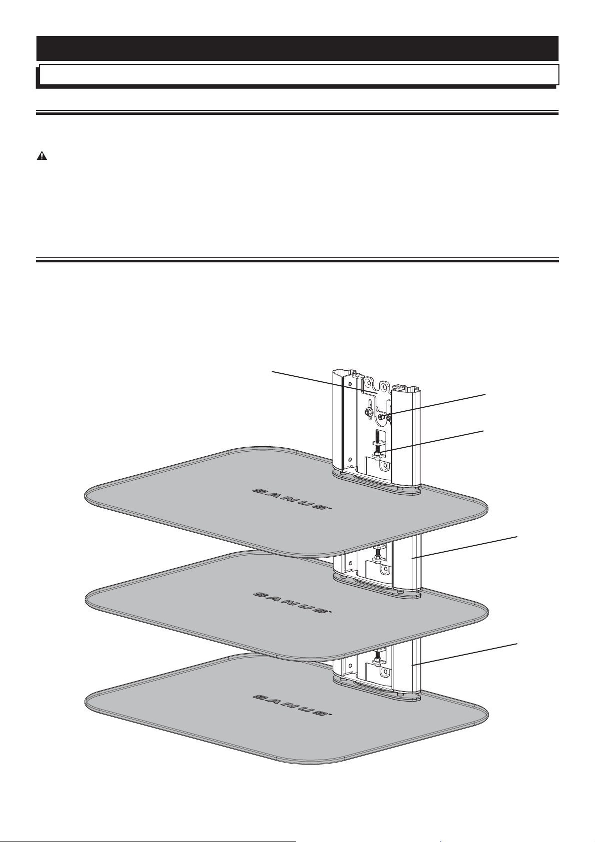
Features and Bene ts
The VMA401:
A. Can be mounted to drywall, wood stud, or concrete.
B. Level can be adjusted by ±7½° post-installation.
C. Height can be adjusted by 1 in. post-installation.
D. Is stackable to accommodate multiple components (not to exceed 7 kg (15 lb) on each shelf).
A
B
C
D
D
6901-002141 <03>
3
Page 4
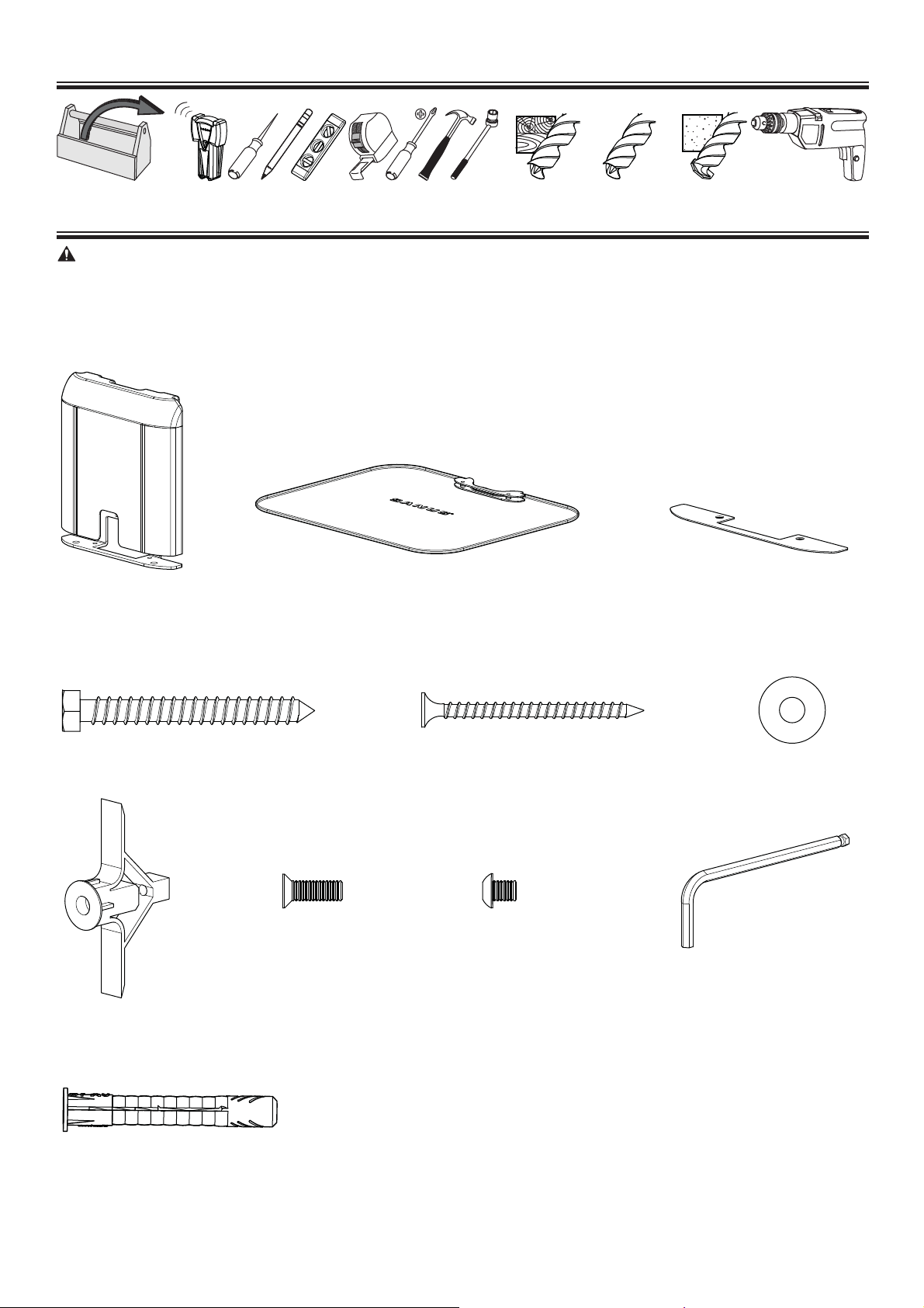
Required Tools
11 mm
(7/16 in.)
3 mm
(1/8 in.)
10 mm
(3/8 in.)
10 mm
(3/8 in.)
Supplied Parts and Hardware
WARNING: This product contains small items that could be a choking hazard if swallowed.
Before starting assembly, verify all parts are included and undamaged. If any parts are missing or damaged, do not return the damaged
item to your dealer; contact Customer Service. Never use damaged parts!
[01] x 1
[02] x 1
[03] x 1
1/4 x 2 ½ in.
[11] x 1
#8 x 2 in.
[04] x 1 [05] x 3
M5 x 20 M5 x 6
[07] x 3
[08] x 2
[09] x 2
[06] x 1
M3
[10] x 1
4
6901-002141 <03>
Page 5
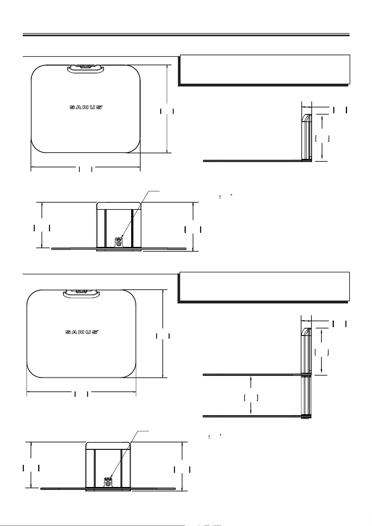
1 Determine Con guration
1-1 Single shelf con guration
18.00
457.2
14.50
368.3
Your VMA401 is 166 mm (6⁄ in.) high. Consider this when determining
wall placement.
See 1-2 for con guration of multiple units.
6.6
166
1.34
33.9
6.11
155.1
1-2 Stacked con guration
POST INSTALLMENT 1" HIEGHT ADJUST
POST INSTALLMENT ROLL
6.55
166.3
7.5
Your VMA401 is 166 mm (6⁄ in.) high. Consider this when determining
wall placement.
IMPORTANT: Begin stacking your VMA401 shelves from the top down.
14.50
368.3
1.34
33.9
6.6
166
6.11
155.1
6901-002141 <03>
18.00
457.2
POST INSTALLMENT 1" HIEGHT ADJUST
POST INSTALLMENT ROLL
6.55
166.3
7.5
5.31
135
5
Page 6
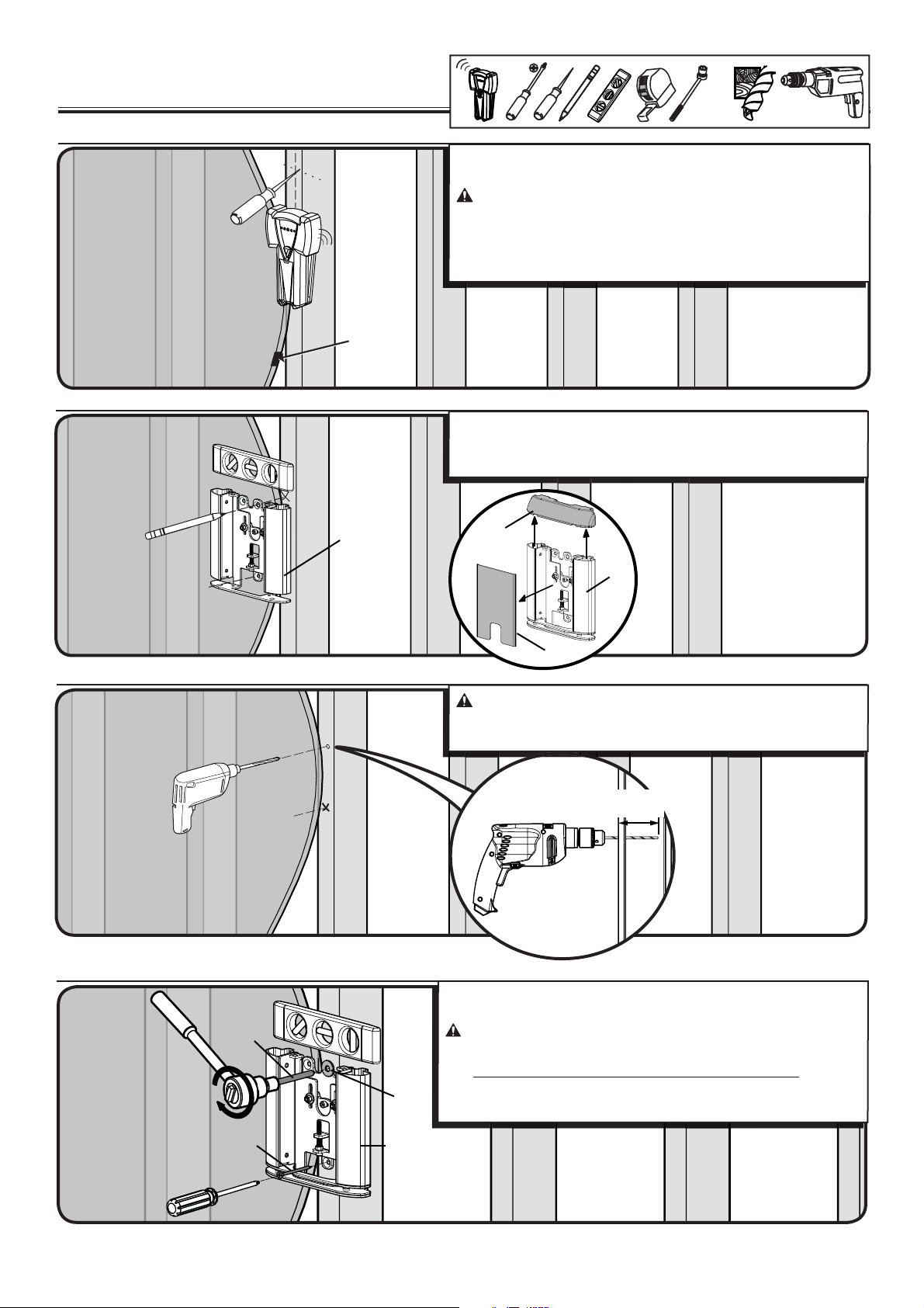
2 Mount the Wall Plate
Wood stud
2-1 Locate stud
2-2 Mark the wall
< 16 mm
(5/8 in.)
11 mm
(7/16 in.)
Verify the center of the stud using an awl, a thin nail, or an edge to
edge stud nder.
CAUTION: Avoid potential personal injuries and property
damage!
Ù Any material covering the wall must not exceed 16 mm (5/8 in.).
Ù Minimum wood stud size: common 51 x 102 mm (2 x 4 in.)
nominal 38 x 89 mm (1½ x 3½ in.).
IMPORTANT: For stacking con gurations, stack from the top down.
Remove the front (F) and top (T) covers from the wall plate [01].
Level the wall plate [01] and mark the hole locations.
3 mm
(1/8 in.)
2-3 Drill pilot holes
2-4 Tighten lag bolt and screw
[01]
(T)
[01]
(F)
CAUTION:
holes MUST be drilled to a depth of 63.5 mm
(1/8 in.) diameter drill bit.
Avoid potential injuries or property damage! Pilot
63.5 mm
(2½ in.)
(2½ in.) using a 3 mm
Use the lag bolt [04] and washer [06] to secure the top of the wall plate.
Use the #8 screw [05] to secure the bottom of the wall plate.
[04]
[05]
[06]
[01]
CAUTION:
lag bolt. To avoid potential injuries or property damage
Ù DO NOT over-tighten the lag bolt [04] or the screw [05].
Ù Tighten the lag bolt [04] only until the washer [06] is pulled rmly
against the wall plate [01].
6
Improper use could reduce the holding power of the
6901-002141 <03>
Page 7
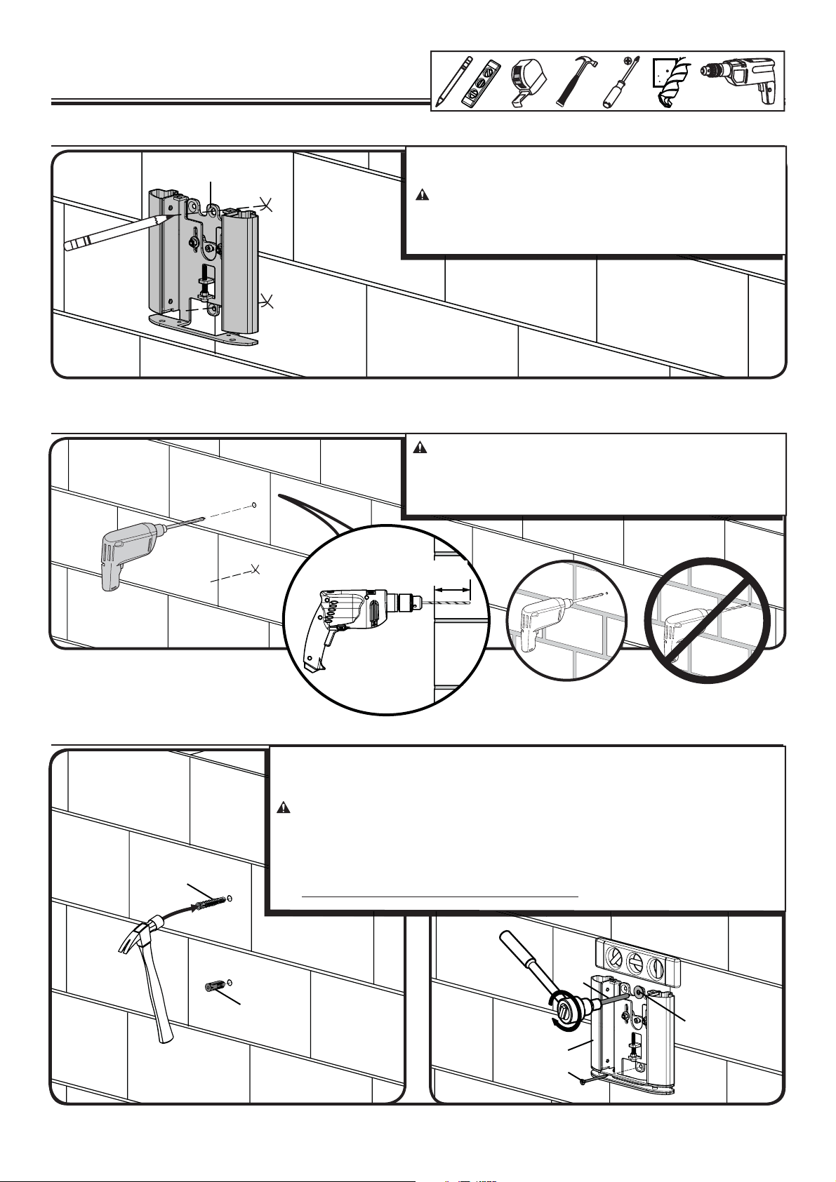
2 Mount the Wall Plate
Solid concrete or concrete block
2-1 Mark the wall
[01]
2-2 Drill pilot holes
10 mm
(3/8 in.)
IMPORTANT: For stacking con gurations, stack from the top down.
Level the wall plate [01] and mark the hole locations.
CAUTION:
Ù Mount the wall plate [01] directly onto the concrete surface.
Ù Minimum solid concrete thickness: 203mm (8 in.).
Ù Minimum concrete block size: 203 x 203 x 406 mm (8 x
Avoid potential injuries or property damage!
8 x 16 in.).
2-3 Insert anchors and screws
Insert anchors [11]/[07].
Use the lag bolt [04], washer [06], and anchor [11] to secure the top of the wall plate. Use the #8
screw [05] and anchor [07] to secure the bottom of the wall plate.
CAUTION:
potential injuries or property damage:
Ù Be sure the anchors [11]/[07] are seated ush with the concrete surface.
Ù Tighten the lag bolt [04] only until the washer [06] is pulled rmly against the wall plate
[11]
Ù DO NOT over-tighten the lag bolt [04] or screw [05].
[01].
CAUTION:
Ù Pilot holes MUST be drilled to a depth of 63.5 mm (
a 10 mm (3/8 in.) diameter drill bit.
Ù Never drill into the mortar between blocks.
63.5mm
(2½ in.)
Improper use could reduce the holding power of the lag bolt. To avoid
Avoid potential injuries or property damage!
2½ in.) using
6901-002141 <03>
[04]
[07]
[06]
[01]
[05]
7
Page 8
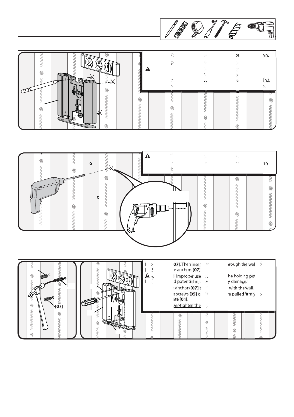
2 Mount the Wall Plate
Drywall
2-1 Mark the wall
[01]
2-2 Drill pilot holes
10 mm
(3/8 in.)
IMPORTANT: For stacking con gurations, stack from the top down.
Level the wall plate [01] and mark the hole locations.
CAUTION:
Ù Mount the wall plate [01] directly onto the wall.
Ù Any material covering the wall must not exceed 13mm (1/2 in.).
Ù Do not install anchors into the seam between drywall pieces.
Avoid potential injuries or property damage!
2-3 Insert anchors and screws
[07]
[07]
[07]
[05]
[01]
[05]
CAUTION:
Pilot holes MUST be drilled to a depth of 38 mm
mm (3/8 in.)
Insert anchors [07]. Then insert screws [05] through the wall plate
[01] and into the anchors [07].
CAUTION:
lag bolt. To avoid potential injuries or property damage:
Ù Be sure the anchors [07] are seated ush with the wall.
Ù Tighten the screws [05] only until they are pulled rmly against
the wall plate [01].
Ù DO NOT over-tighten the screws [05].
Avoid potential injuries or property damage!
(1½ in.) using a 10
diameter drill bit.
38 mm
(1½ in.)
Improper use could reduce the holding power of the
[05]
8
6901-002141 <03>
Page 9
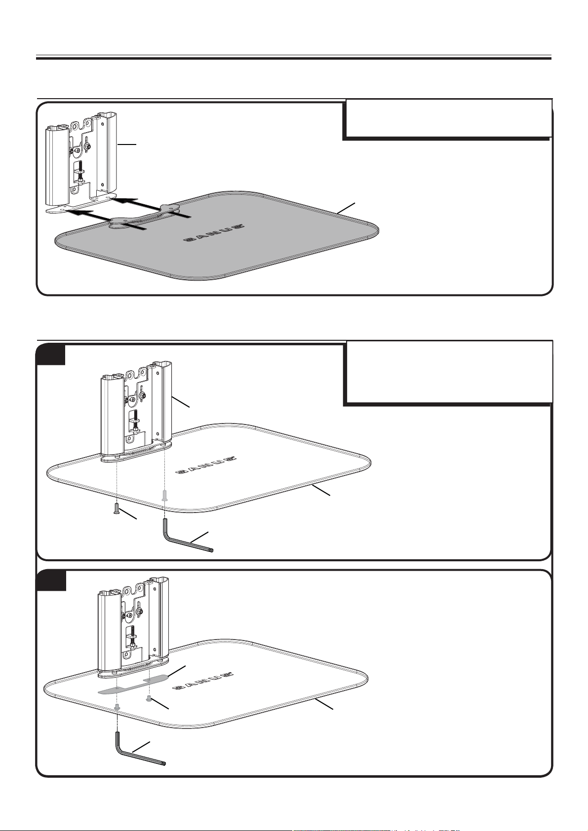
3 Attach Glass to Wall Plate
3-1 Attach glass shelf
[01]
3-2 Secure glass shelf
1
Slide the glass shelf [02] into the wall plate [01].
Line up the holes in the shelf to the holes in the wall
plate, as shown.
[02]
1. Secure the glass shelf [02] to the wall plate [01]
using screws [08].
2. Attach the safety plate [03] to the glass shelf
[02] using screws [09].
2
[01]
[02]
[08]
[10]
[03]
6901-002141 <03>
[10]
[09]
[02]
9
Page 10
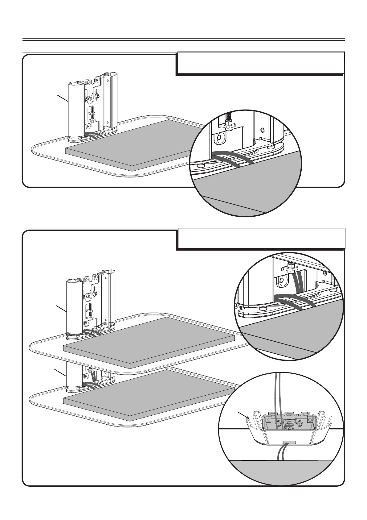
4 Manage Cables
4-1 Single shelf con gurations
[01]
Cables can be routed through the opening in the lower back of the
wall plate [01].
4-2 Stacked con gurations
[01]
[01]
Cables can be routed through the inside of the wall plates [01] for
stacked con gurations.
10
[01]
6901-002141 <03>
Page 11
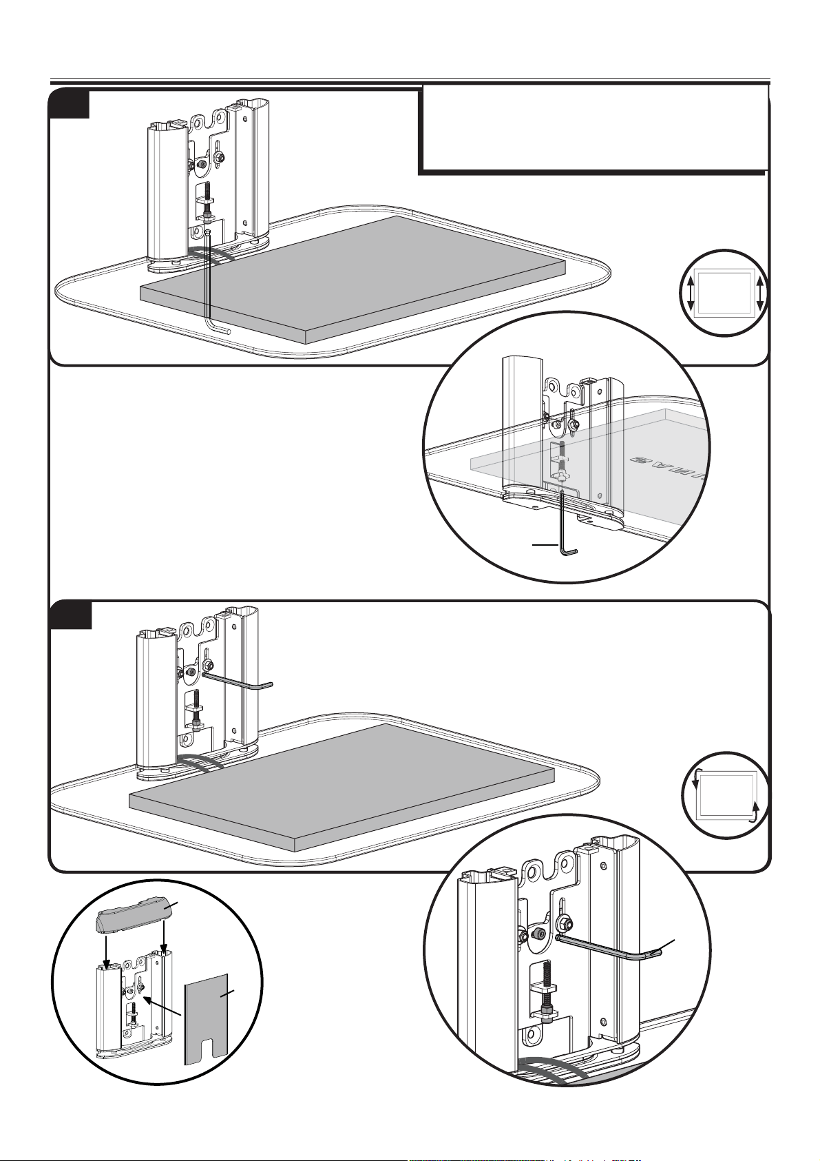
5 Adjustments
1
1. Adjust the height using the allen key [10].
2. Adjust level by hand. Tighten using the allen key [10].
NOTE: Replace the top (T) and front (F) covers when you are
done routing cables and making adjustments.
2
[10]
(T)
[10]
6901-002141 <03>
(F)
11
Page 12
Français
CONSIGNES DE SÉCURITÉ IMPORTANTES – CONSERVEZ CES INSTRUCTIONS – VEUILLEZ LIRE ATTENTIVEMENT LE
MANUEL AVANT D’UTILISER CE PRODUIT
Caractéristiques techniques Voir à la page 3
Ù Capacité de charge – NE PAS DÉPASSER: 7 kg (15 lb).
Ù Niveau: ±7.5°
ATTENTION: Évitez les dommages matériels et les blessures!
Ù Ne pas utiliser ce produit à d’autres ns que celles spéci ées par le fabricant.
Ù Le mur doit pouvoir supporter cinq fois le poids total du moniteur et du support.
Ù Si vous ne comprenez pas toutes ces instructions ou si vous avez des doutes sur la sécurité de l'installation, du montage ou de l’utilisation de ce produit,
veuillez contacter un installateur quali é ou le service à la clientèle.
Ù Le fabricant n’est pas responsable des blessures ou des dommages causés par une mauvaise utilisation ou un montage incorrect.
Fonctions et avantages Voir à la page 3
Le modèle VMA401:
A. peut être installé sur cloison sèche, béton, mur en montant de bois ou d'acier.
B. le niveau peut être réglé à ±7.5° après l'installation.
C. la hauteur peut être réglée à 25mm (1po) après l'installation.
D. est empilable pour loger plusieurs composants (ne pas excéder 7kg (15lb) par tablette).
Outils nécessaires Voir à la page 4
Pièces et quincaillerie fournies Voir à la page 4
AVERTISSEMENT: Ce produit contient de petites pièces qui peuvent représenter un risque d’étou ement.
Avant de commencer l’assemblage, assurez-vous que toutes les pièces sont présentes et qu’elles ne sont pas endommagées. Si une pièce est manquante ou
endommagée, ne retournez pas les pièces endommagées à votre revendeur. Contactez plutôt le service clientèle. N’utilisez jamais de pièces endommagées!
1 Déterminez la con guration Voir à la page 5
1-1 Con guration à une tablette
Votre modèle VMA401 mesure 166mm (6,6po) de hauteur. Veuillez considérer cet aspect lorsque vous choisirez l’emplacement sur le mur. Veuillez aussi
considérer l'emplacement et la taille de votre téléviseur.
Consultez la section 1-2 pour la con guration de plusieurs éléments.
1-2 Con guration d'éléments empilés
Votre modèle VMA401 mesure 166mm (6,6po) de hauteur. Veuillez considérer cet aspect lorsque vous choisirez l’emplacement sur le mur. Veuillez aussi
considérer l'emplacement et la taille de votre téléviseur.
IMPORTANT: Commencez à empiler les tablettes du VMA401 à partir du haut vers le bas.
2 Montage de la plaque murale Montant de bois Voir l'illustration à la page 6
2-1 Trouvez les montants
Véri ez le centre du montant à l’aide d’un poinçon ou d’un clou n, ou utilisez un localisateur bord à bord.
ATTENTION: Évitez les dommages matériels et les blessures!
Ù L’épaisseur du matériau de revêtement de mur ne doit pas excéder 16mm (5/8po).
Ù Dimension minimale du montant de bois: commune 51 x 102mm (2 x 4po) (nominale 38 x 89mm (1½ x 3½po))
2-2 Marquez l'emplacement sur le mur
IMPORTANT: Pour les con guration d'éléments empilés, commencez du haut vers le bas.
Enlevez le cache avant (F) et le cache supérieur (T) de la plaque murale [01]. Mettez la plaque murale [01] à niveau et marquez les emplacements des trous.
2-3 Percez des trous de guidage
ATTENTION: Évitez tout dommage matériel ou blessure! Les avant-trous DOIVENT être percés à une profondeur de 63,5mm (2,5po) à l’aide d’un
foret de 3mm (1/8po).
2-4 Serrez les boulons tire-fond et les vis
Utilisez le boulon tire-fond [04] et une rondelle [06] pour xer le haut du support mural. Utilisez des vis #8 [05] pour xer le bas de la plaque murale.
ATTENTION:
A n d’éviter tout dommage matériel ou blessure
Ù NE PAS trop serrer les boulons tire-fond [04] ou la vis [05].
Ù Serrez les boulons tire-fond [04] jusqu'à ce que les rondelles [06] s’appuient fermement sur la plaque murale [01].
12
Évitez tout dommage matériel ou blessure! Une utilisation inadéquate peut réduire la force de rétention du boulon tire-fond.
:
6901-002141 <03>
Page 13

2 Installation de la plaque murale Béton coulé ou blocs de béton Voir à la page 7
2-1 Marquez l'emplacement sur le mur
Mettez la plaque murale [01] à niveau et marquez les emplacements des trous.
IMPORTANT: Pour les con guration d'éléments empilés, commencez du haut vers le bas.
ATTENTION:
Ù Montez la plaque murale [01] directement sur la surface de béton.
Ù Épaisseur minimale du béton coulé: 203mm (8po)
Ù Dimension minimale du bloc de béton: 203x203x406mm (8x
Évitez tout dommage matériel ou blessure!
8 x 16po)
2-2 Percez des trous de guidage
ATTENTION: Évitez tout dommage matériel ou blessure!
Ù Les avant-trous DOIVENT être percés à une profondeur de 63,5 mm (2,5po) à l’aide d’un foret de 10mm (3/8po).
Ù Ne jamais percer dans le mortier entre les blocs.
2-3 Insérez les douilles et les vis
Insérez les douilles [11], [07] Insérez ensuite les vis [04], [05] dans la plaque murale [01] et dans les douilles [11], [07].
ATTENTION: Évitez tout dommage matériel ou blessure! Une utilisation inadéquate peut réduire la force de rétention du boulon tire-fond.
A n d’éviter tout dommage matériel ou blessure:
Ù Assurez-vous que les douilles à expansion [11], [07] ne dépassent pas de la surface de béton.
Ù Vissez les vis [04], [05] jusqu'à ce qu'elles soient bien appuyées contre la plaque murale [01].
Ù NE PAS trop serrer les vis [04], [05].
2 Montage de la plaque muralesur des murs en cloison sèche Voir à la page 8
2-1 Marquez l'emplacement sur le mur
Mettez la plaque murale [01] à niveau et marquez les emplacements des trous.
IMPORTANT: Pour les con guration d'éléments empilés, commencez du haut vers le bas.
ATTENTION: Évitez tout dommage matériel ou blessure!
Ù Montez la plaque murale [01] directement sur le mur.
Ù L’épaisseur du matériau de revêtement de mur ne doit pas excéder 13mm (1/2po).
Ù Ne pas installer les chevilles d'ancrage dans l'espace entre deux cloisons sèches.
2-2 Percez des trous de guidage
ATTENTION: Évitez tout dommage matériel ou blessure!
Les avant-trous DOIVENT être percés à une profondeur de 38mm
2-3 Insérez les douilles et les vis
Insérez les douilles [07] Insérez ensuite les vis [05] dans la plaque murale [01] et dans les douilles [07].
ATTENTION: Évitez tout dommage matériel ou blessure! Une utilisation inadéquate peut réduire la force de rétention du boulon tire-fond.
A n d’éviter tout dommage matériel ou blessure:
Ù Assurez-vous que les douilles à expansion [07] ne dépassent pas de la surface du mur.
Ù Vissez les vis [05] jusqu'à ce qu'elles soient bien appuyées contre la plaque murale [01].
Ù NE PAS trop serrer les vis [05].
(1,5po) à l’aide d’un foret de 10mm (3/8po).
3 Fixez la tablette en verre à la plaque murale Voir à la page 9
3-1 Fixez la tablette en verre
Glissez la tablette en verre [02] dans la plaque murale [01]. Alignez les trous de la tablette à ceux de la plaque murale, comme illustré.
3-2 Installez solidement la tablette en verre
1. Vissez la tablette en verre [02] à la plaque murale [01] en utilisant les vis [08].
2. Fixez la plaque de sécurité [03] sur la tablette de verre [02] à l'aide des vis [09].
4 Gestion des câbles Voir à la page 10
4-1 Con gurations à une tablette
Acheminez les câbles par l'ouverture du bas à l'arrière de la plaque murale [01].
4-1 Con gurations d'éléments empilés
Acheminez les câbles à l'intérieur des plaques murales [01], pour les con gurations d'éléments empilés.
5 Réglages Voir à la page 11
1. Réglage de la hauteur à l'aide de la clé Allen [10].
2. Réglez le niveau à la main. Serrer avec la clé Allen [10].
6901-002141 <03>
13
Page 14

Deutsch
WICHTIGE SICHERHEITSHINWEISE – BEWAHREN SIE DIESE HINWEISE SORGFÄLTIG AUF – LESEN SIE VOR DEM
GEBRAUCH DES PRODUKTS BITTE DAS GESAMTE HANDBUCH
Technische Daten Siehe Seite 3
Ù Höchstzulässiges Gesamtgewicht-NICHT ÜBERSCHREITEN: 7 kg (15 lb).
Ù Neigungswinkel: ±7.5°
VORSICHT: Vermeiden Sie Verletzungen und Sachschäden!
Ù Verwenden Sie dieses Produkt nur für den vom Hersteller ausdrücklich angegebenen Zweck.
Ù Die Wand muss das Fün ache des Gesamtgewichts von Monitor und Halterung tragen können.
Ù Falls Sie diese Anleitung nicht verstehen sollten oder Zweifel bezüglich der sicheren Montage, des Zusammenbaus oder der Verwendung des Produkts
haben, kontaktieren Sie den Kundendienst oder einen quali zierten Auftragnehmer.
Ù Der Hersteller haftet nicht für Schäden oder Verletzungen, die durch falsche Montage oder Verwendung verursacht werden.
Merkmale und Vorteile Siehe Seite 3
Das VMA401:
A. kann an Gips- und Betonwänden sowie Holz- und Stahlbalken montiert werden.
B. kann nach der Montage um ±7,5° geneigt werden.
C. kann nach der Montage um 25 mm (1 in.) in der Höhe verstellt werden.
D. ist stapelbar, so dass mehrere Komponenten angeordnet werden können (max. 7 kg (15 lb.) pro Boden).
Erforderliche Werkzeuge Siehe 4
Mitgelieferte Teile und Befestigungsmaterialien Siehe Seite 4
WARNUNG: Dieses Produkt enthält kleine Teile, die beim Verschlucken zum Erstickungstod führen können.
Prüfen Sie vor Montagebeginn, ob alle Teile vorhanden und unbeschädigt sind. Falls Teile fehlen oder beschädigt sind, bringen Sie das Produkt nicht zum
Händler zurück, sondern wenden Sie sich an den Kundendienst. Verwenden Sie niemals beschädigte Teile!
1 Bestimmen der Kon guration Siehe Seite 5
1-1 Kon guration mit einem Boden
Das VMA401 ist 166 mm (6,6 in.) hoch. Beachten Sie dies, wenn Sie die Montagestelle an der Wand festlegen. Berücksichtigen Sie außerdem die Größe und die
Position des Fernsehers.
Siehe 1-2 für die Kon guration mit mehreren Böden.
1-2 Stapelkon guration
Das VMA401 ist 166 mm (6,6 in.) hoch. Beachten Sie dies, wenn Sie die Montagestelle an der Wand festlegen. Berücksichtigen Sie außerdem die Größe und die
Position des Fernsehers.
WICHTIG: Stapeln Sie die VMA401-Böden von oben nach unten.
2 Montage der Wandplatte Holzbalken Siehe Seite 6
2-1 Suchen Sie den Balken
Stechen Sie mit einer Ahle oder einem dünnen Nagel die Mitte des Balkens an, oder verwenden Sie einen Kante-zu-Kante-Balkensucher.
VORSICHT: Vermeiden Sie Verletzungen und Sachschäden!
Ù Jegliches Material, das die Wand bedeckt, darf 16mm (5/8 in.) nicht überschreiten.
Ù Mindestmaße der Holzbalken: üblich 51 x 102 mm/2 x 4 in. (nominell 38 x 89 mm/1½ x 3½ in.)
2-2 Markieren Sie Bohrstellen an der Wand
WICHTIG: Bei Stapelkon gurationen von oben nach unten stapeln.
Entfernen Sie die vordere (F) und die obere (T) Abdeckung von der Wandplatte [01]. Richten Sie die Wandplatte [01] aus und markieren Sie die Stellen für
die Bohrlöcher.
2-3 Bohren Sie Vorbohrungen
VORSICHT: Vermeiden Sie Verletzungen und Sachschäden! Vorbohrungen MÜSSEN mit einem 3-mm-Bohrer (1/8 in.) bis zu 63,5 mm (2,5 in.) tief
gebohrt werden.
2-4 Ziehen Sie die Schrauben fest
Befestigen Sie die Wandhalterung oben mit der Ankerschraube [04] und der Unterlegscheibe [06]. Befestigen Sie die Wandhalterung unten mit der
#8-Schraube [05].
VORSICHT:
Vermeiden Sie Verletzungen und Sachschäden:
Ù Ziehen Sie die Ankerschraube [04] bzw. die Schraube [05] NICHT zu fest an.
Ù Ziehen Sie die Ankerschraube [04] nur so weit an, bis die Unterlegscheibe [06] fest an der Wandplatte [01] anliegt.
Vermeiden Sie Verletzungen und Sachschäden! Eine unsachgemäße Verwendung kann die Haltekraft der Ankerschraube verringern.
14
6901-002141 <03>
Page 15

2 Montage der Wandplatte Massivbeton oder Betonblöcke Siehe Seite 7
2-1 Markieren Sie Bohrstellen an der Wand
Richten Sie die Wandplatte [01] aus und markieren Sie die Stellen für die Bohrlöcher.
WICHTIG: Bei Stapelkon gurationen von oben nach unten stapeln.
VORSICHT:
Ù Montieren Sie die Wandplatte [01] direkt an der Beton äche.
Ù Mindestdicke der Massivbetonwand: 203 mm (8 in.)
Ù Mindestmaße der Betonblöcke: 203 x 203 x 406 mm (8 x
Vermeiden Sie Verletzungen und Sachschäden!
8 x 16 in.)
2-2 Bohren Sie Vorbohrungen
VORSICHT: Vermeiden Sie Verletzungen und Sachschäden!
Ù Vorbohrungen MÜSSEN mit einem 10 mm-Bohrer (3/8 in.) bis zu 63,5 mm (2,5 in.) tief gebohrt werden.
Ù Bohren Sie niemals in den Mörtel zwischen Steinen.
2-3 Einsetzen der Ankerschrauben und Dübel
Setzen Sie die Ankerschraubendübel [11], [07] ein. Führen Sie die Ankerschrauben [04], [05] durch die Wandplatte [01] in die Dübel [11], [07] ein.
VORSICHT: Vermeiden Sie Verletzungen und Sachschäden! Eine unsachgemäße Verwendung kann die Haltekraft der Ankerschraube verringern.
Vermeiden Sie Verletzungen und Sachschäden:
Ù Stellen Sie sicher, dass die Dübel [11], [07] bündig mit der Betonober äche abschließen.
Ù Ziehen Sie Ankerschrauben [04], [05] nur so weit an, bis sie fest an der Wandplatte [01] anliegen.
Ù Ziehen Sie die Ankerschrauben [04], [05] NICHT zu fest an.
2 Montage der Wandplatte Gipswand Siehe Seite 8
2-1 Markieren Sie Bohrstellen an der Wand
Richten Sie die Wandplatte [01] aus und markieren Sie die Stellen für die Bohrlöcher.
WICHTIG: Bei Stapelkon gurationen von oben nach unten stapeln.
VORSICHT: Vermeiden Sie Verletzungen und Sachschäden!
Ù Montieren Sie die Wandplatte [01] direkt an der Wand.
Ù Jegliches Material, das die Wand bedeckt, darf 13mm (1/2 in.) nicht überschreiten.
Ù Setzen Sie keine Dübel in die Fugen zwischen den Gipsplatten ein.
2-2 Bohren Sie Vorbohrungen
VORSICHT: Vermeiden Sie Verletzungen und Sachschäden!
Vorbohrungen MÜSSEN mit einem 10-mm-Bohrer
2-3 Einsetzen der Ankerschrauben und Dübel
Setzen Sie die Ankerschraubendübel [07] ein. Führen Sie die Ankerschrauben [05] durch die Wandplatte [01] in die Dübel [07] ein.
VORSICHT: Vermeiden Sie Verletzungen und Sachschäden! Eine unsachgemäße Verwendung kann die Haltekraft der Ankerschraube verringern.
Vermeiden Sie Verletzungen und Sachschäden:
Ù Stellen Sie sicher, dass die Dübel [07] bündig mit der Wand abschließen.
Ù Ziehen Sie Ankerschrauben [05] nur so weit an, bis sie fest an der Wandplatte [01] anliegen.
Ù Ziehen Sie die Ankerschrauben [05] NICHT zu fest an.
(3/8 in.) bis zu 38 mm (1,5 in.) tief gebohrt werden.
3 Anbringen von Glasböden an der Wandplatte Siehe Seite 9
3-1 Anbringen des Glasbodens
Schieben Sie den Glasboden [02] in die Wandplatte [01]. Richten Sie die Löcher im Glasboden mit den Löchern in der Wandplatte aus, wie dargestellt.
3-2 Befestigen des Glasbodens
1. Befestigen Sie den Glasboden [02] mithilfe der Schrauben [08] an der Wandplatte [01].
2. Befestigen Sie die Sicherungsplatte [03] mithilfe der Schrauben [09] am Glasboden [02].
4 Kabelführung Siehe Seite 10
4-1 Kon gurationen mit einem Boden
Die Kabel können durch die Ö nung unten an der Rückseite der Wandplatte [01] durchgeführt werden.
4-1 Stapelkon gurationen
Bei Stapelkon gurationen können die Kabel an den Innenseiten der Wandplatten [01] verlegt werden.
5 Einstellungen Siehe Seite 11
1. Stellen Sie die Höhe mithilfe des Inbusschlüssels [10] ein.
2. Stellen Sie den Neigungswinkel manuell ein. Dann mit dem Inbusschlüssel [10] festziehen.
6901-002141 <03>
15
Page 16

Español
INSTRUCCIONES DE SEGURIDAD IMPORTANTES. CONSÉRVELAS. LEA TODO EL MANUAL ANTES DE UTILIZAR
ESTE PRODUCTO
Especi caciones Ver página 3
Ù Peso máximo admitido —NO LO EXCEDA—: 7 kg (15 lb)
Ù Nivelación: ±7,5°
PRECAUCIÓN: Evite lesiones y daños materiales.
Ù No utilice este producto para ningún otro propósito que no sea el explícitamente especi cado por el fabricante.
Ù La pared debe soportar cinco veces el peso del televisor y del soporte juntos.
Ù Si no entiende las instrucciones o si tiene dudas acerca de la seguridad de la instalación, del ensamblado o del uso del producto, contáctese con el
servicio de atención al cliente o llame a un técnico cali cado.
Ù El fabricante no se responsabiliza por ningún daño o lesión resultante del montaje incorrecto o del uso indebido.
Características y bene cios Ver página 3
El VMA401:
A. puede instalare en paredes de placas de yeso (drywall), de hormigón o con montantes de madera o de acero.
B. permite ajustar la nivelación en hasta ±7,5° después de la instalación.
C. permite ajustar la altura hasta 25 mm (1 in) después de la instalación.
D. es apilable a n de alojar múltiples equipos (peso máximo admitido por estante: 7 kg [15 lb]).
Herramientas necesarias Ver página 4
Piezas y elementos de jación suministrados Ver página 4
ADVERTENCIA: Este producto contiene piezas pequeñas que, si fuesen tragadas, podrían producir as xia.
Antes de iniciar el ensamblaje, compruebe que todas las piezas estén incluidas y en buenas condiciones. Si faltan piezas o alguna está dañada, no devuelva el
artículo al distribuidor; póngase en contacto con el servicio de atención al cliente. Nunca utilice piezas deterioradas.
1 Determinar la con guración Ver página 5
1-1 Con guración de un solo estante
El VMA401 mide 166 mm (6,6 in) de altura. Tenga en cuenta esta medida al determinar el lugar de instalación. También tenga en cuenta la ubicación y el tamaño
del televisor.
Consulte el paso 1-2 para con guraciones de varios estantes.
1-2 Con guración de varios estantes
El VMA401 mide 166 mm (6,6 in) de altura. Tenga en cuenta esta medida al determinar el lugar de instalación. También tenga en cuenta la ubicación y el tamaño
del televisor.
IMPORTANTE: Instale los estantes VMA401 comenzando por el superior.
2 Instalar la placa mural Montantes de madera Ver página 6
2-1 Localizar el montante
Veri que el centro del montante con un punzón o un clavo delgado, o bien utilice un detector de bordes de montantes.
PRECAUCIÓN: Evite lesiones y daños materiales.
Ù El material que recubre la pared no debe exceder los 16 mm (5/8 in).
Ù Tamaño mínimo del montante de madera: común 51 mm x 102 mm [2 in x 4 in] (nominal 38 mm x 89 mm [1½ in x 3½ in])
2-2 Marcar la pared
IMPORTANTE: Para con guraciones de varios estantes, comience por el estante superior.
Quite la cubierta frontal (F) y la cubierta superior (T) de la placa mural [01]. Nivele la placa mural [01] y marque la ubicación de los ori cios.
2-3 Hacer los ori cios guía
PRECAUCIÓN: Evite lesiones y daños materiales. Los ori cios guía DEBEN realizarse con una mecha de 3 mm (1/8 in) de diámetro hasta una profundidad
de 63,5 mm
(2,5 in).
2-4 Ajustar los tornillos
Fije la parte superior de la placa mural con el tornillo tirafondo [04] y la arandela [06] provistos. Fije la parte inferior de la placa mural con el tornillo nro. 8 [05].
PRECAUCIÓN:
y daños materiales:
Ù NO ajuste en exceso el tornillo tirafondo [04] ni el tornillo [05].
Ù Ajuste el tornillo tirafondo [04] solamente hasta que la arandela [06] quede rme contra la placa mural [01].
16
Evite lesiones y daños materiales. El uso indebido podría reducir la capacidad de retención de los tornillos tirafondo. Para evitar lesiones
6901-002141 <03>
Page 17

2 Instalar la placa mural Hormigón o bloques de cemento Ver página 7
2-1 Marcar la pared
Nivele la placa mural [01] y marque la ubicación de los ori cios.
IMPORTANTE: Para con guraciones de varios estantes, comience por el estante superior.
PRECAUCIÓN:
Ù Instale la placa mural [01] directamente sobre la super cie de hormigón.
Ù Espesor mínimo del hormigón: 203 mm (8 in)
Ù Tamaño mínimo del bloque de cemento: 203 x 203 x 406 mm (8 x
Evite lesiones y daños materiales.
8 x 16 in)
2-2 Hacer los ori cios guía
PRECAUCIÓN: Evite lesiones y daños materiales.
Ù Los ori cios guía DEBEN realizarse con una mecha de 10 mm (3/8 in) de diámetro hasta una profundidad de 63,5 mm (2,5 in).
Ù Nunca perfore el cemento que une los bloques.
2-3 Insertar los anclajes y los tornillos
Inserte los anclajes [11], [07]. Luego, pase los tornillos [04], [05] por la placa mural [01] e insértelos en los anclajes [11], [07].
PRECAUCIÓN: Evite lesiones y daños materiales. El uso indebido podría reducir la capacidad de retención de los tornillos tirafondo. Para evitar lesiones
y daños materiales:
Ù Cerciórese de que los anclajes [11], [07] hayan quedado nivelados respecto de la super cie de hormigón.
Ù Ajuste los tornillos [04], [05] solamente hasta que queden rmes contra la placa mural [01].
Ù NO ajuste en exceso los tornillos [04], [05].
2 Instalar la placa mural Pared de placas de yeso (Drywall) Ver página 8
2-1 Marcar la pared
Nivele la placa mural [01] y marque la ubicación de los ori cios.
IMPORTANTE: Para con guraciones de varios estantes, comience por el estante superior.
PRECAUCIÓN: Evite lesiones y daños materiales.
Ù Instale la placa mural [01] directamente sobre la pared.
Ù El material que recubre la pared no debe exceder los 13 mm (1/2 in).
Ù No coloque los anclajes en la unión de las placas.
2-2 Hacer los ori cios guía
PRECAUCIÓN: Evite lesiones y daños materiales.
Los ori cios guía DEBEN realizarse con una mecha de
2-3 Insertar los anclajes y los tornillos
Inserte los anclajes [07]. Luego, pase los tornillos [05] por la placa mural [01] e insértelos en los anclajes [07].
PRECAUCIÓN: Evite lesiones y daños materiales. El uso indebido podría reducir la capacidad de retención de los tornillos tirafondo. Para evitar lesiones
y daños materiales:
Ù Cerciórese de que los anclajes [07] hayan quedado nivelados respecto de la pared.
Ù Ajuste los tornillos [05] solamente hasta que queden rmes contra la placa mural [01].
Ù NO ajuste en exceso los tornillos [05].
10 mm (3/8 in) de diámetro hasta una profundidad de 38 mm (1,5 in).
3 Colocar el estante de vidrio en la placa mural Ver página 9
3-1 Colocar el estante de vidrio
Deslice el estante de vidrio [02] e insértelo en la placa mural [01]. Alinee los ori cios del estante con los ori cios de la placa mural, como se muestra en la
ilustración.
3-2 Fijar el estante de vidrio
1. Fije el estante de vidrio [02] a la placa mural [01] utilizando los tornillos suministrados [08].
2. Fije la placa de seguridad [03] al estante de virio [02] utilizando los tornillos suministrados [09].
4 Organización de cables Ver página 10
4-1 Con guración de un solo estante
Los cables pueden pasarse por la abertura ubicada en la parte posterior inferior de la placa mural [01].
4-1 Con guración de varios estantes
Los cables pueden pasarse por el interior de las placas murales [01].
5 Ajustes Ver página 11
1. Ajuste la altura con la llave Allen provista [10].
2. Ajuste la nivelación en forma manual. Apriete con la llave Allen [10].
6901-002141 <03>
17
Page 18

Português
INFORMAÇÕES DE SEGURANÇA IMPORTANTES – GUARDE ESTAS INSTRUÇÕES – LEIA O MANUAL INTEIRO ANTES
DE USAR
Especi cações Consulte a página 3
Ù Capacidade de peso—NÃO EXCEDER: 7 kg (15 lb.)
Ù Nível: ±7,5°
CUIDADO: Evite possíveis ferimentos pessoais e dano à propriedade!
Ù Não use este produto para uma nalidade diferente daquela explicitamente especi cada pelo fabricante.
Ù A parede tem que ser capaz de suportar cinco vezes o peso do monitor e do suporte combinados.
Ù Se houver dúvida sobre essas instruções ou sobre a segurança da instalação, montagem ou uso deste produto, entre em contato com o Atendimento
ao Cliente ou ligue para um prestador de serviços quali cado.
Ù O fabricante não se responsabiliza por danos ou ferimentos causados por montagem ou uso incorretos.
Recursos e benefícios Consulte a página 3
O VMA401:
A. pode ser montado em parede de gesso, pino de madeira, parafusos para concreto ou aço.
B. o nível pode ser ajustado em ±7,5° após a instalação.
C. a altura pode ser ajustada em 25 mm (1 pol.) após a instalação.
D. é empilhável para acomodar vários componentes (não deve exceder 7 kg (15 lb.) em cada prateleira).
Ferramentas necessárias Consulte a página 4
Peças e ferramentas fornecidas Consulte a página 4
AVISO: Este produto contém itens pequenos que podem oferecer risco de sufocamento se engolidos.
Antes de iniciar a montagem, veri que se todas as peças estão incluídas e intactas. Se qualquer peça estiver faltando ou se estiver dani cada, não devolva o
item dani cado para seu fornecedor; entre em contato com o Atendimento ao Cliente. Nunca use peças dani cadas!
1 Determine a con guração Consulte a página 5
1-1 Con guração de prateleira única
Seu VMA401 tem 166 mm (6.6 pol.) de altura. Considere isso ao determinar a localização da parede. Considere também o local e o tamanho de sua TV.
Consulte 1-2 para con guração de várias unidades.
1-2 Con guração empilhado
Seu VMA401 tem 166 mm (6.6 pol.) de altura. Considere isso ao determinar a localização da parede. Considere também o local e o tamanho de sua TV.
IMPORTANTE: Comece a empilhar suas prateleiras VMA401 de cima para baixo.
2 Monte a Placa da parede Pino de madeira Consulte a página 6
2-1 Encontre o pino
Veri que o centro do pino com um furador ou um prego no, ou use um localizador de pino borda a borda.
CUIDADO: Evite possíveis ferimentos pessoais e dano à propriedade!
Ù Qualquer material que cubra a parede não deve exceder 16 mm (5/8 pol.).
Ù Tamanho mínimo do pino de madeira: comum 51x102mm (2 x 4 pol.) (nominal 38 x 89 mm (1½ x 3½ pol.))
2-2 Marque a parede
IMPORTANTE: Para con gurações de empilhamento, empilhe de cima para baixo.
Remova as tampas frontal (F) e superior (T) da placa da parede [01]. Nivele a placa na parede [01] e marque os locais de furo.
2-3 Faça os furos-piloto
CUIDADO: Evite possíveis ferimentos ou dano à propriedade! Os furos-piloto DEVEM ser perfurados em uma profundidade de 63,5 mm (2,5 pol.),
usando uma broca de 3 mm (1/8 pol.) de diâmetro.
2-4 Aperte parafuso e parafuso interfragmentário
Use o parafuso interfragmentário [04] e a arruela [06] para prender a parte superior da montagem de parede. Use o parafuso 8 [05] para prender a parte
inferior da placa de parede.
CUIDADO:
Para evitar possíveis ferimentos ou dano à propriedade.
Ù NÃO aperte demais o parafuso interfragmentário [04] nem o parafuso [05].
Ù Aperte os parafusos interfragmentários [04] somente até a arruela [06] ser puxada rmemente contra a placa da parede [01].
18
Evite possíveis ferimentos ou dano à propriedade! O uso incorreto pode reduzir a potência de xação do parafuso interfragmentário.
6901-002141 <03>
Page 19

2 Monte a Placa da parede - Concreto sólido ou bloco de concreto Consulte a página 7
2-1 Marque a parede
Nivele a placa na parede [01] e marque os locais de furo.
IMPORTANTE: Para con gurações de empilhamento, empilhe de cima para baixo.
CUIDADO:
Ù Monte a placa da parede [01] diretamente na superfície de concreto.
Ù Espessura mínima do concreto sólido: 203 mm (8 pol.)
Ù Tamanho mínimo do bloco de concreto: 203 x 203 x 406 mm (8 x
Evite possíveis ferimentos ou dano à propriedade!
8 x 16 pol.)
2-2 Faça os furos-piloto
CUIDADO: Evite possíveis ferimentos ou dano à propriedade!
Ù Os furos-piloto DEVEM ser perfurados até uma profundidade de 63,5 mm (2,5 pol.), usando uma broca de 10 mm (3/8 pol.) de diâmetro.
Ù Nunca perfure na argamassa entre os blocos.
2-3 Insira âncoras e parafusos
Insira as âncoras [11], [07]. Insira os parafusos [04], [05] através da placa de parede [01] e nas âncoras [11], [07].
CUIDADO: Evite possíveis ferimentos ou dano à propriedade! O uso incorreto pode reduzir a potência de xação do parafuso interfragmentário.
Para evitar possíveis ferimentos ou dano à propriedade:
Ù Certi que-se de que as âncoras [11], [07] estejam assentadas de forma plana na superfície de concreto.
Ù Aperte os parafusos [04], [05] somente até serem puxados rmemente contra a placa de parede [01].
Ù NÃO aperte demais os parafusos [04], [05].
2 Monte a Placa da parede parede de gesso Consulte a página 8
2-1 Marque a parede
Nivele a placa na parede [01] e marque os locais de furo.
IMPORTANTE: Para con gurações de empilhamento, empilhe de cima para baixo.
CUIDADO: Evite possíveis ferimentos ou dano à propriedade!
Ù Monte a placa da parede [01] diretamente na parede.
Ù Qualquer material que cubra a parede não deve exceder 13mm (1/2 pol.)
Ù Não instale âncoras na costura entre as partes da parede de gesso.
2-2 Faça os furos-piloto
CUIDADO: Evite possíveis ferimentos ou dano à propriedade!
Os furos-piloto DEVEM ser perfurados até uma profundidade de 38 mm
2-3 Insira âncoras e parafusos
Insira as âncoras [07]. Insira os parafusos [05] através da placa de parede [01] e nas âncoras [07].
CUIDADO: Evite possíveis ferimentos ou dano à propriedade! O uso incorreto pode reduzir a potência de xação do parafuso interfragmentário.
Para evitar possíveis ferimentos ou dano à propriedade:
Ù Certi que-se de que as âncoras [07] estejam assentadas de forma plana na parede.
Ù Aperte os parafusos [05] somente até serem puxados rmemente contra a placa de parede [01].
Ù NÃO aperte demais os parafusos [05].
(1,5 pol.), usando uma broca de 10 mm (3/8 pol.) de diâmetro.
3 Prenda o vidro na placa de parede Consulte a página 9
3-1 Prenda a prateleira de vidro
Deslize a prateleira de vidro [02] na placa de parede [01]. Alinhe os furos na prateleira aos furos na placa de parede, como mostrado.
3-2 Prenda a prateleira de vidro
1. Prenda a prateleira de vidro [02] na placa de parede [01] usando parafusos [08].
2. Prenda a placa de segurança [03] na a prateleira de vidro [02] usando parafusos [09].
4 Gerenciamento dos cabos Consulte a página 10
4-1 Con gurações de prateleira única
Os cabos podem ser orientados pela abertura na parte inferior traseira da placa de parede [01].
4-1 Con gurações de empilhado
Os cabos podem ser orientados pelo interior das placas de parede [01]. para con gurações empilhadas.
5 Ajustes Consulte a página 11
1. Ajuste a altura usando a chave allen [10].
2. Ajuste o nível com a mão. Aperte com a chave allen [10].
6901-002141 <03>
19
Page 20

Nederlands
BELANGRIJKE VEILIGHEIDSINSTRUCTIES – BEWAAR DEZE INSTRUCTIES – LEES DE VOLLEDIGE HANDLEIDING
VOORAFGAAND AAN HET GEBRUIK
Speci caties zie pagina 3
Ù Gewichtscapaciteit-NIET OVERSCHRIJDEN: 7 kg (15 lb.)
Ù Waterpas: ±7.5°
VOORZICHTIG: Voorkom mogelijk persoonlijk letsel en apparatuurschade!
Ù Gebruik dit product niet voor doeleinden die niet expliciet zijn gespeci ceerd door de fabrikant.
Ù De wand moet geschikt zijn om vijf keer het gecombineerde gewicht van het scherm en de montagesteun te ondersteunen.
Ù Als u deze instructies niet begrijpt of twijfelt over de veiligheid van de installatie, de montage of het gebruik van dit product, neemt u contact op met de
klantenservice of belt u met een erkend vakman.
Ù De fabrikant is niet verantwoordelijk voor schade of letsel als gevolg van onjuiste montage of verkeerd gebruik.
Kenmerken en voordelen zie pagina 3
De VMA401:
A. kan bevestigd worden op gipsplaat, houtskeletmuur, beton of metal stud.
B. stand kan nog tot ±7.5° afgesteld worden na installatie.
C. hoogte kan nog tot 25mm (1 inch) afgesteld worden na installatie.
D. kan gestapeld worden om meerdere componenten te kunnen herbergen (die de gewichtscapaciteit van 7 kg (15 lb.) per plank niet mogen overschrijden).
Benodigd gereedschap zie pagina 4
Bijgeleverde onderdelen en materialen zie pagina 4
WAARSCHUWING: Dit product bevat kleine onderdelen die verstikkingsgevaar kunnen opleveren als ze worden ingeslikt.
Controleer voor de montage of alle onderdelen onbeschadigd aanwezig zijn. Mochten er onderdelen ontbreken of beschadigd zijn, breng het beschadigde
item dan niet terug naar de dealer, maar neem contact op met de klantenservice. Gebruik nooit beschadigde onderdelen!
1 De constructie bepalen zie pagina 5
1-1 Enkelvoudige constructie
Uw VMA401 is 166 mm (6,6 in.) hoog. Houd hier rekening mee als u de plaats op de wand bepaalt. Let ook op de positie en grootte van uw tv.
Raadpleeg 1-2 voor de constructie van meerdere units.
1-2 Gestapelde constructie
Uw VMA401 is 166 mm (6,6 inch) hoog. Houd hier rekening mee als u de plaats op de wand bepaalt. Let ook op de positie en grootte van uw tv.
BELANGRIJK: Werk bij het stapelen van uw VMA401 planken van boven naar beneden.
2 De wandplaat bevestigen Houtskeletmuur zie pagina 6
2-1 De drager zoeken
Controleer het midden van de drager met een priem of een dunne spijker, of gebruik een balkzoeker van rand tot rand.
VOORZICHTIG: Voorkom mogelijk persoonlijk letsel en apparatuurschade!
Ù Materialen die de muur bedekken, mogen niet dikker zijn dan 16 mm (5/8 inch).
Ù Minimale grootte houten drager: gebruikelijk 51 x 102 mm (2 x 4 inch) (nominaal 38 x 89 mm (1½ x 3½ inch))
2-2 Markeringen op de wand aanbrengen
BELANGRIJK: Werk bij gestapelde constructies van boven naar beneden.
Verwijder de bedekking van de voor- (F) en bovenkant (T) van de wandplaat [01]. Plaats de wandplaat [01] waterpas en markeer de locaties van de gaten.
2-3 Montagegaten boren
VOORZICHTIG: Voorkom mogelijk letsel of schade aan meubilair! De montagegaten MOETEN tot een diepte van 63,5 mm (2,5 inch) worden
geboord met behulp van een boorkop van 3 mm (1/8 inch).
2-4 Vastdraaien van de bout en schroef
Gebruikt de bout [04] en het afstandsringetje [06] om de bovenkant van de wandplaat te bevestigen. Gebruik de #8 schroef [05] om te onderkant van de
wandplaat te bevestigen.
VOORZICHTIG:
letsel of materiële schade.
Ù Draai de bout [04] en de schroef [05] NIET te strak.
Ù Draai de bout [04] alleen vast tot het afstandsringetje [06] stevig tegen de wandplaat [01] zit.
20
Voorkom mogelijk letsel of schade aan meubilair! Een onjuist gebruik kan de grip van de bout verminderen. Voorkom persoonlijk
6901-002141 <03>
Page 21

2 De wandplaat bevestigen Massief beton of betonblok zie pagina 7
2-1 Markeringen op de wand aanbrengen
BELANGRIJK: Werk bij gestapelde constructies van boven naar beneden.
Plaats de wandplaat [01] waterpas en markeer de locaties van de gaten.
VOORZICHTIG:
Ù Bevestig de wandplaat [01] rechtstreeks op het betonnen oppervlak.
Ù Minimale dikte massief beton: 203 mm (8 inch)
Ù Minimale grootte betonblok: 203 x 203 x 406 mm (8 x
Voorkom mogelijk letsel of schade aan meubilair!
8 x 16 inch)
2-2 Montagegaten boren
VOORZICHTIG: Voorkom mogelijk letsel of schade aan meubilair!
Ù De montagegaten MOETEN tot een diepte van 63,5 mm (2,5 inch) worden geboord met behulp van een boorkop van 10 mm (3/8 inch).
Ù Boor nooit in het cement tussen blokken.
2-3 Pluggen en schroeven plaatsen
Plaats de pluggen [11], [07]. Steek vervolgens de schroeven [04], [05] door de wandplaat [01] en in de pluggen [11], [07].
BELANGRIJK: Werk bij gestapelde constructies van boven naar beneden.
VOORZICHTIG: Voorkom mogelijk letsel of schade aan meubilair! Een onjuist gebruik kan de grip van de bout verminderen. Voorkom persoonlijk
letsel of materiële schade:
Ù Zorg ervoor dat de pluggen [11], [07] helemaal in het betonoppervlak worden geplaatst.
Ù Draai de schroeven [04], [05] alleen vast tot ze stevig tegen de wandplaat [01] zitten.
Ù Draai de schroeven [04], [05] NIET te strak.
2 De wandplaat bevestigen Gipsplaat zie pagina 8
2-1 Markeringen op de wand aanbrengen
Plaats de wandplaat [01] waterpas en markeer de locaties van de gaten.
BELANGRIJK: Werk bij gestapelde constructies van boven naar beneden.
VOORZICHTIG: Voorkom mogelijk letsel of schade aan meubilair!
Ù Bevestig de wandplaat [01] rechtstreeks op de wand.
Ù Materialen die de muur bedekken, mogen niet dikker zijn dan 13mm (1/2 inch).
Ù Bevestig geen pluggen in de naden tussen gipsplaten.
2-2 Montagegaten boren
VOORZICHTIG: Voorkom mogelijk letsel of schade aan meubilair!
De montagegaten MOETEN tot een diepte van 38 mm
2-3 Pluggen en schroeven plaatsen
Plaats de pluggen [07]. Steek vervolgens de schroeven [05] door de wandplaat [01] en in de pluggen [07].
VOORZICHTIG: Voorkom mogelijk letsel of schade aan meubilair! Een onjuist gebruik kan de grip van de bout verminderen. Voorkom persoonlijk
letsel of materiële schade:
Ù Zorg ervoor dat de pluggen [07] helemaal in de wand worden geplaatst.
Ù Draai de schroeven [05] alleen vast tot ze stevig tegen de wandplaat [01] zitten.
Ù Draai de schroeven [05] NIET te strak.
(1,5 inch) worden geboord met behulp van een boorkop van 10 mm (3/8 inch).
3 Het glas aan de wandplaat bevestigen zie pagina 9
3-1 De glazen plank plaatsen
Schuif de glazen plank [02] in de wandplaat [01]. Zorg dat de gaten in de plank op dezelfde plaats zitten als de gaten in de wandplaat, zoals weergegeven.
3-2 De glazen plank bevestigen
1. Bevestig de glazen plank [02] aan de wandplaat [01] met behulp van de schroeven [08].
2. Bevestig de veiligheidsplaat [03] aan de glazen plaat [02] met behulp van de schroeven [09].
4 Kabelvoering zie pagina 10
4-1 Enkelvoudige constructies
Kabels kunnen door de opening onderaan de achterzijde van de wandplaat [01] worden geleid.
4-1 Gestapelde constructies
In gestapelde constructies kunnen de kabels via de binnenkant van de wandplaten [01] worden geleid.
5 Aanpassingen zie pagina 11
1. Gebruik de inbussleutel [10] om de hoogte aan te passen.
2. Stel de gewenste stand met de hand af. Draai de bout vast met de inbussleutel [10].
6901-002141 <03>
21
Page 22

Italiano
ISTRUZIONI DI SICUREZZA IMPORTANTI – CONSERVARE QUESTE ISTRUZIONI – LEGGERE TUTTE LE ISTRUZIONI
PRIMA DI USARE QUESTO PRODOTTO
Speci che Vedere a pagina 3
Ù Portata-NON ECCEDERE: 7 kg (15 libbre)
Ù Livello: ±7.5°
ATTENZIONE: evitare la possibilità di danni alle cose o lesioni alle persone!
Ù Non utilizzare il prodotto per qualsiasi scopo non esplicitamente speci cato dal produttore.
Ù La parete deve essere in grado di sostenere cinque volte il peso complessivo del monitor e di tutti i supporti.
Ù Se le istruzioni risultassero poco chiare o in casi dubbi riguardo la sicurezza dell'installazione, dell'assemblaggio o dell'utilizzo del prodotto, contattare
l'Assistenza clienti oppure rivolgersi a un tecnico quali cato.
Ù Il produttore non è responsabile per danni o lesioni personali derivanti dall'assemblaggio o dall'uso non corretti.
Caratteristiche e vantaggi Vedere a pagina 3
VMA401:
A. può essere installato su cartongesso, montanti in legno, calcestruzzo o montanti in acciaio.
B. il livello può essere regolato con la postinstallazione ±7.5°.
C. l'altezza può essere regolata con la post-installazione di 25 mm (1 pollici).
D. è modulabile per posizionare più componenti (non supera i 7 kg (15 libbre) su ogni mensola).
Strumenti richiesti Vedere a pagina 4
Pezzi e componenti forniti Vedere a pagina 4
ATTENZIONE: questo prodotto comprende elementi di piccole dimensioni che potrebbero causare il so ocamento in caso di ingestione.
Prima di iniziare il montaggio, assicurarsi di avere tutti i pezzi, e che questi non siano stati danneggiati. Se qualsiasi pezzo manca o risulta danneggiato, non
riportare l'elemento danneggiato in negozio, rivolgersi invece all'Assistenza clienti. Non usare mai pezzi danneggiati!
1 Determinare la con gurazione Vedere a pagina 5
1-1 Con gurazione singola mensola
Il VMA401 è alto 166 mm (6,6 pollici). Considerare questo aspetto quando si considera l'installazione a muro. Considerare inoltre la posizione e le dimensioni
del televisore.
Vedere 1-2 per la con gurazione di diverse unità.
1-2 Con gurazione modulare
Il VMA401 è alto 166 mm (6,6 pollici). Considerare questo aspetto quando si considera l'installazione a muro. Considerare inoltre la posizione e le dimensioni
del televisore.
IMPORTANTE: iniziare a impilare le mensole VMA401 dal basso verso l'alto.
2 Montare il perno di legno della piastra a muro Vedere a pagina 6
2-1 Individuare il montante
Veri care il centro del montante con un punteruolo, un chiodo sottile, oppure con un cercamontanti per rilevare la distanza da bordo a bordo.
ATTENZIONE: evitare la possibilità di danni alle cose o lesioni alle persone!
Ù Lo spessore di qualsiasi materiale che copre la parete non deve eccedere i 16 mm (5/8 poll.).
Ù Dimensione minima del montante di legno: normale 51 x 102 mm (2 x 4 pollici) (nominale 38 x 89 mm (1½ x 3½ pollici))
2-2 Contrassegnare la parete
IMPORTANTE: per le con gurazioni impilabili, iniziare dal basso verso l’alto.
Rimuovere i coperchi anteriore (F) e superiore (T) dalla piastra a muro [01]. Mettere a livello la piastra a muro [01] e contrassegnare le posizioni dei fori.
2-3 Praticare i fori guida
ATTENZIONE: evitare la possibilità di danni alle cose o lesioni alle persone! I fori guida DEVONO essere praticati a una profondità di 63,5 mm (2.5 in.),
con una punta per trapano dal diametro di 3 mm (1/8 poll.).
2-4 Stringere il tirafondo e la vite
Utilizzare il tirafondo [04] e la rondella [06] per fermare il rivestimento del supporto a parete. Utilizzare la vite n.8 [05] per fermare la parte sottostante della
piastra a muro.
ATTENZIONE:
Per evitare la possibilità di danni alle cose o lesioni alle persone.
Ù NON serrare eccessivamente i tirafondi [04] o la vite [05].
Ù Serrare il tirafondo [04] solo no a quando la rondella [06] non è a livello con la piastra a muro [01].
22
evitare la possibilità di danni alle cose o lesioni alle persone! l’utilizzo improprio potrebbe ridurre la capacità di tenuta dei tirafondi.
6901-002141 <03>
Page 23

2 Montare la piastra a muro Calcestruzzo o blocchi di calcestruzzo Vedere a pagina 7
2-1 Contrassegnare la parete
Mettere a livello la piastra a muro [01] e contrassegnare le posizioni dei fori.
IMPORTANTE: per le con gurazioni impilabili, iniziare dal basso verso l’alto.
ATTENZIONE:
Ù Montare la piastra a muro [01] direttamente sulla super cie di calcestruzzo.
Ù Spessore minimo del calcestruzzo: 203 mm (8 pollici)
Ù Dimensione minima del blocco di calcestruzzo: 203 x 203 x 406 mm (8 x
evitare la possibilità di danni alle cose o lesioni alle persone!
8 x 16 pollici)
2-2 Praticare i fori guida
ATTENZIONE: evitare la possibilità di danni alle cose o lesioni alle persone!
Ù I fori guida DEVONO essere praticati a una profondità di 63,5 mm (2,5 pollici), con una punta per trapano del diametro di 10 mm (3/8 poll.).
Ù Non praticare mai i fori nei giunti di malta tra i blocchi di calcestruzzo.
2-3 Inserire i tasselli e le viti
Inserire i tasselli [11], [07]. Inserire le viti [04], [05] attraverso la piastra a muro [01] e nei tasselli [11], [07].
ATTENZIONE: evitare la possibilità di danni alle cose o lesioni alle persone! l’utilizzo improprio potrebbe ridurre la capacità di tenuta dei tirafondi.
Per evitare la possibilità di danni alle cose o lesioni alle persone:
Ù assicurarsi che i tasselli [11], [07] siano inseriti a livello rispetto alla super cie di calcestruzzo.
Ù Serrare le viti [04], [05] solo no a quando le rondelle non sono a livello con la piastra a muro [01].
Ù NON serrare eccessivamente le viti [04], [05].
2 Montare la piastra a muro al calcestruzzo Vedere a pagina 8
2-1 Contrassegnare la parete
Mettere a livello la piastra a muro [01] e contrassegnare le posizioni dei fori.
IMPORTANTE: per le con gurazioni impilabili, iniziare dal basso verso l’alto.
ATTENZIONE: evitare la possibilità di danni alle cose o lesioni alle persone!
Ù Montare la piastra a muro [01] direttamente sulla parete.
Ù Lo spessore di qualsiasi materiale che copre la parete non deve eccedere i 13mm (1/2 poll.).
Ù Non installare tasselli nella giunzione tra elementi in cartongesso.
2-2 Praticare i fori guida
ATTENZIONE: evitare la possibilità di danni alle cose o lesioni alle persone!
I fori guida DEVONO essere praticati a una profondità di 38 mm
2-3 Inserire i tasselli e le viti
(1.5 in.) con una punta per trapano del diametro di 10 mm (3/8 pollici)
Inserire i tasselli [07]. Inserire le viti [05] attraverso la piastra a muro [01] e nei tasselli [07].
ATTENZIONE: evitare la possibilità di danni alle cose o lesioni alle persone! l’utilizzo improprio potrebbe ridurre la capacità di tenuta dei tirafondi. Per
evitare la possibilità di danni alle cose o lesioni alle persone:
Ù assicurarsi che i tasselli
Ù Serrare le viti [05] solo no a quando le rondelle non sono a livello con la piastra a muro [01].
Ù NON serrare eccessivamente le viti [05].
[07] siano inseriti a livello rispetto alla parete.
3 Collegare il vetro alla piastra a muro Vedere a pagina 9
3-1 Collegare la mensola in vetro
Far scorrere la mensola in vetro [02] nella piastra a muro [01]. Allineare i fori nella mensola ai fori nella piastra a muro, come mostrato.
3-2 Fissare la mensola in vetro
1. Fissare la mensola in vetro [02] alla piastra a muro[01] utilizzando le viti [08].
2. Collegare la piastra di sicurezza [03] alla mensola in vetro [02] utilizzando le viti [09].
4 Gestire i cavi Vedere a pagina 10
4-1 Con gurazioni singola mensola
I cavi possono essere inseriti nell'apertura nella parte posteriore bassa della piastra a muro [01].
4-1 Con gurazioni modulari
I cavi possono essere instradati all'interno delle piastre a muro [01]. per le con gurazioni modulari.
5 Regolazioni Vedere a pagina 11
1. Regolare l'altezza utilizzando una chiave a brugola [10].
2. Regolare il livello a mano. Serrare con la chiave a brugola [10].
6901-002141 <03>
23
Page 24

Suomi
TÄRKEITÄ TURVALLISUUSOHJEITA – SÄILYTÄ NÄMÄ OHJEET – LUE OPAS KOKONAAN ENNEN LAITTEEN
KÄYTTÄMISTÄ
Tekniset tiedot katso sivu 3
Ù Painokapasiteetti-ÄLÄ YLITÄ: 7 kg (15 lb.)
Ù Taso: ±7.5°
VAROITUS: Vältä mahdolliset henkilövahingot ja laitevauriot!
Ù Käytä laitetta vain valmistajan ilmoittamiin käyttötarkoituksiin.
Ù Seinän täytyy kestää viisi kertaa näytön ja telineen yhteispaino.
Ù Jos et ymmärrä näitä ohjeita, tai jos sinulla on laitteen kokoamiseen, asennukseen tai käyttämiseen liittyviä kysymyksiä, ota yhteyttä asiakaspalveluun tai
soita valtuutetulle rakentajalle.
Ù Valmistaja ei ole vastuussa virheellisen kokoamisen tai käytön aiheuttamista vaurioista tai vahingoista.
Ominaisuudet ja edut Katso sivu 3
VMA401:
A. voidaan kiinnittää kipsilevyyn, koolauspuuhun, betoniin tai teräskoolaukseen.
B. vaakatasoa voidaan säätää±7.5° asennuksen jälkeen.
C. korkeutta voidaan säätää 25mm (1 in.) asennuksen jälkeen.
D. voidaan pinota useamman komponentin (hyllykohtainen paino ei saa ylittää 7 kg (15 lb.)) kiinnittämiseksi.
Tarvittavat työkalut katso sivu 4
Toimitetut osat ja kiinnitysosat katso sivu 4
VAROITUS: Laite sisältää pieniä osia, jotka voivat aiheuttaa tukehtumisvaaran.
Varmista ennen kokoamista, että pakkaus sisältää kaikki osat ja ettei osissa ole vaurioita. Jos osia puuttuu tai ne ovat vaurioituneita, ota yhteyttä
asiakaspalveluun; älä palauta vaurioituneita osia valmistajalle. Älä käytä vaurioituneita osia!
1 Määritä kiinnitystapa Katso sivu 5
1-1 Yhden hyllyn kiinnitys
VMA401 korkeus on 166 mm (6.6 in.). Ota tämä huomioon kiinnityskohtaa päätettäessä. Ota huomioon myös TV:n sijainti ja koko.
Katso useamman yksikön kiinnitystapa kohdasta 1-2.
1-2 Pinottu kiinnitystapa
VMA401 korkeus on 166 mm (6.6 in.). Ota tämä huomioon kiinnityskohtaa päätettäessä. Ota huomioon myös TV:n sijainti ja koko.
TÄRKEÄÄ: Aloita VMA401-hyllyjen pinoaminen ylhäältä alas.
2 Seinälevyn kiinnittäminen koolauspuuhun Katso sivu 6
2-1 Etsi koolauspuut
Etsi koolauspuiden keskikohta lävistimellä, ohuella naulalla tai mittarilla.
VAROITUS: Vältä mahdolliset henkilövahingot ja laitevauriot!
Ù Seinää peittävän materiaalin paksuus saa olla enintään 16 mm (5/8 in.).
Ù Koolauspuiden vähimmäiskoko: tavallinen 51 x 102 mm (2 x 4 in.) (nimellinen 38 x 89 mm (1½ x 3½ in.))
2-2 Merkitse reikien paikat seinälle
TÄRKEÄÄ: Pinoamista käytettäessä, aloita pinoaminen ylhäältä alas.
Irrota etu- (F) ja yläsuojat (T) seinälevystä [01]. Aseta seinälevy [01] vaakasuoraan ja merkitse reikien paikat.
2-3 Poraa ohjausreiät
VAROITUS: Vältä mahdolliset henkilövahingot ja laitevauriot! Ohjausreikien syvyyden TÄYT YY olla vähintään 63,5 mm (2.5 in.) ja ne täytyy porata
halkaisijaltaan 3 mm:n (1/8 in.) terällä.
2-4 Kansiruuvin kiinnittäminen
Kiinnitä seinälevyn yläosa kansiruuvilla [04] ja aluslevyllä [06]. Kiinnitä seinälevyn alaosa #8 ruuvilla [05].
VAROITUS:
henkilövahingot ja laitevauriot.
Ù ÄLÄ kiristä kansiruuvia [04] tai ruuvia [05] liian tiukalle.
Ù Kiristä kansiruuvia [04] vain siihen asti, kunnes aluslevy [06] painuu tiukasti seinälevyä [01] vasten.
24
Vältä mahdolliset henkilövahingot ja laitevauriot! Virheellinen käyttö voi alentaa kansiruuvien pitovoimaa. Vältä mahdolliset
6901-002141 <03>
Page 25

2 Seinälevyn kiinnittäminenBetoni tai betoniharkko Katso sivu 7
2-1 Merkitse reikien paikat seinälle
Aseta seinälevy [01] vaakasuoraan ja merkitse reikien paikat.
TÄRKEÄÄ: Pinoamista käytettäessä, aloita pinoaminen ylhäältä alas.
VAROITUS:
Ù Kiinnitä seinälevy [01] suoraan betonipinnalle.
Ù Betonin vähimmäispaksuus: 203mm (8 in.)
Ù Betoniharkon vähimmäiskoko: 203 x 203 x 406 mm (8 x
Vältä mahdolliset henkilövahingot ja laitevauriot!
8 x 16 in.)
2-2 Poraa ohjausreiät
VAROITUS: Vältä mahdolliset henkilövahingot ja laitevauriot!
Ù Ohjausreikien syvyyden TÄYT YY olla vähintään 63,5 mm (2,5 in.) ja ne täytyy porata halkaisijaltaan 10 mm:n (3/8 in.) terällä.
Ù Älä poraa harkkojen välissä olevaan laastiin.
2-3 Aseta ankkurit ja ruuvit
Kiinnitä ankkurit [11], [07]. Kiinnitä sitten ruuvit [04], [05] seinälevyn [01] läpi ankkureihin [11], [07].
VAROITUS: Vältä mahdolliset henkilövahingot ja laitevauriot! Virheellinen käyttö voi alentaa kansiruuvien pitovoimaa. Vältä mahdolliset
henkilövahingot ja laitevauriot:
Ù Varmista, että ankkurit [11], [07] ovat samassa tasossa betonipinnan kanssa.
Ù Kiristä kansiruuveja [04], [05] vain siihen asti, kunnes ne painuvat tiukasti seinälevyä [01] vasten.
Ù ÄLÄ KIRISTÄ ruuveja liian tiukalle [04], [05].
2 Seinälevyn kiinnittäminenKipsilevy Katso sivu 8
2-1 Merkitse reikien paikat seinälle
JAseta seinälevy [01] vaakasuoraan ja merkitse reikien paikat.
TÄRKEÄÄ: Pinoamista käytettäessä, aloita pinoaminen ylhäältä alas.
VAROITUS: Vältä mahdolliset henkilövahingot ja laitevauriot!
Ù Kiinnitä seinälevy [01] suoraan betonipinnalle.
Ù Seinää peittävän materiaalin paksuus saa olla enintään 13mm (1/2 in.).
Ù Älä asenna ankureita kipsilevyjen välisiin saumoihin.
2-2 Poraa ohjausreiät
VAROITUS: Vältä mahdolliset henkilövahingot ja laitevauriot!
Ohjausreikien syvyyden TÄYT YY olla vähintään 38 mm
2-3 Aseta ankkurit ja ruuvit
Kiinnitä ankkurit [07]. Kiinnitä sitten ruuvit [05] seinälevyn [01] läpi ankkureihin [07].
VAROITUS: Vältä mahdolliset henkilövahingot ja laitevauriot! Virheellinen käyttö voi alentaa kansiruuvien pitovoimaa. Vältä mahdolliset
henkilövahingot ja laitevauriot:
Ù Varmista, että ankkurit [07] ovat samassa tasossa betonipinnan kanssa.
Ù Kiristä kansiruuveja [05] vain siihen asti, kunnes ne painuvat tiukasti seinälevyä [01] vasten.
Ù ÄLÄ KIRISTÄ ruuveja liian tiukalle [05].
(1.5 in.) ja ne täytyy porata halkaisijaltaan 10 mm:n (3/8 in.) terällä.
3 Lasin kiinnittäminen seinälevyyn Katso sivu 9
3-1 Asenna lasihylly
Liu'uta lasihylly [02] seinälevyyn [01]. Kohdista hyllyn reiät seinälevyn reikien kanssa kuvan osoittamalla tavalla.
3-2 Kiinnitä lasihylly
1. Kiinnitä lasihylly [02] seinälevyyn [01] ruuveilla [08].
2. Kiinnitä turvalevy [03] lasihyllyyn [02] ruuveilla [09].
4 Kaapelisuojat Katso sivu 10
4-1 Yhden hyllyn kiinnitys
Kaapelit voidaan viedä seinälevyn [01] takana olevan ala-aukon läpi.
4-1 Pinottu kiinnitystapa
Kaapelit voidaan viedä seinälevyjen [01] sisällä.
5 Säädöt Katso sivu 11
1. Säädä korkeutta kuusiokoloavaimella [10].
2. Aseta vaakataso käsin. Kiristä kuusiokoloavaimella [10].
6901-002141 <03>
25
Page 26

Svenska
VIKTIGA SÄKERHETSANVISNINGAR – SPARA DESSA ANVISNINGAR – LÄS HELA BRUKSANVISNINGEN INNAN DU
ANVÄNDER DENNA PRODUKT
Speci kationer Se sidan 3
Ù Viktkapacitet – ÖVERSKRID INTE: 7 kg (15 lb.)
Ù Nivå: ±7.5°
FÖRSIKTIGT: Undvik risk för personskador och materiella skador!
Ù Använd inte denna produkt för andra ändamål än dem som uttryckligen omnämns av tillverkaren.
Ù Väggen måste kunna bära en vikt på upp till fem gånger bildskärm och upphängning tillsammans.
Ù Om du inte förstår dessa anvisningar eller är tveksam om installationen, monteringen eller användningen är säker, kontakta kundtjänst eller en kvali ce-
rad tekniker.
Ù Tillverkaren kan inte hållas ansvarig för skador eller olycksfall som förorsakats av felaktig montering eller användning.
Funktioner och fördelar Se sidan 3
VMA401:
A. kan monteras på vägg med gipsplattor, träreglar, betong eller metallreglar.
B. nivån kan justeras med ±7.5° efter installationen.
C. höjden kan justeras med 25mm (1 tum) efter installationen.
D. kan staplas för att få plats med era komponenter (får inte överstiga 7 kg (15 lb.) på varje hylla).
Verktyg som behövs Se sidan 4
Medföljande delar och monteringstillbehör Se sidan 4
VARNING: Den här produkten innehåller små delar som kan utgöra kvävningsrisk om de sväljs.
Innan du påbörjar hopmonteringen ska du kontrollera att alla delar nns med och är intakta. Om någon del saknas eller är skadad ska du inte returnera den
skadade produkten till din återförsäljare, utan vända dig direkt till kundtjänst. Använd aldrig skadade delar!
1 Bestäm kon guration Se sidan 5
1-1 Montering av separat hylla
VMA401 är 166 mm (6,6 tum) hög. Tänk på detta när du bestämmer var du placerar den på väggen. Ha också TV:ns placering och storlek i åtanke.
Se 1-2 för kon guration av era enheter.
1-2 Staplad kon guration
VMA401 är 166 mm (6,6 tum) hög. Tänk på detta när du bestämmer var du placerar den på väggen. Ha också TV:ns placering och storlek i åtanke.
VIKTIGT: Börja stapla VMA401-hyllorna med den översta först.
2 Montera väggplattan Träreglar Se sidan 6
2-1 Leta upp regeln
Markera regelns mitt med en pryl eller en smal spik, eller använd en regelsökare (kant till kant).
FÖRSIKTIGT: Undvik risk för personskador och materiella skador!
Ù Material som täcker väggen får inte överstiga 16 mm (5/8 tum).
Ù Minsta storlek på träregel: gemensam 51 x 102 mm (2 x 4 tum) (nominell 38 x 89 mm (1½ x 3½ tum))
2-2 Markera på väggen
VIKTIGT: Vid stapling, börja alltid med den översta hyllan.
Avlägsna skydden på framsidan (F) och översidan (T) av väggplattan [01]. Se till att väggplattan [01] är rak och markera hålplatserna.
2-3 Borra pilothål
FÖRSIKTIGT: Undvik risk för personskador och materiella skador! Pilothålen MÅSTE borras till ett djup av 63,5 mm (2,5 tum) med en 3 mm (1/8 tum)
borrspets.
2-4 Dra åt träskruv och skruv
Använd träskruv [04] och bricka [06] för att sätta fast överdelen av väggfästet. Använd #8-skruven [05] för att sätta fast nederdelen av väggplattan.
FÖRSIKTIGT:
personskador och materiella skador:
Ù DRA INTE åt träskruven [04] eller skruven [05] för hårt.
Ù Dra endast åt träskruven [04] tills brickan [06] sitter ordentligt fast jäms med väggplattan [01].
26
Undvik risk för personskador och materiella skador! Olämplig användning kan minska träskruvens hålle ekt. För att undvika risk för
6901-002141 <03>
Page 27

2 Montera väggplattan - Massiv betong eller betongblock Se sidan 7
2-1 Markera på väggen
Se till att väggplattan [01] är rak och markera hålplatserna.
VIKTIGT: Vid stapling, börja alltid med den översta hyllan.
FÖRSIKTIGT:
Ù Montera väggplattan [01] direkt på betongytan.
Ù Minimitjocklek på massiv betong: 203mm (8 tum)
Ù Minimistorlek på betongblock: 203 x 203 x 406 mm (8 x
Undvik risk för personskador och materiella skador!
8 x 16 tum)
2-2 Borra pilothål
FÖRSIKTIGT: Undvik risk för personskador och materiella skador!
Ù Pilothålen MÅSTE borras till ett djup av 63,5 mm (2,5 tum) med en 10 mm (3/8 tum) borrspets.
Ù Borra aldrig i fogarna mellan cementblocken.
2-3 Sätt i ankare och skruvar
Sätt i ankare [11], [07]. För sedan in skruvarna [04], [05] genom väggplattan [01] och in i ankarna [11], [07].
VIKTIGT: Vid stapling, börja alltid med den översta hyllan.
FÖRSIKTIGT: Undvik risk för personskador och materiella skador! Olämplig användning kan minska träskruvens hålle ekt. För att undvika risk för
personskador och materiella skador:
Ù Se till att ankarna [11], [07] sitter plant mot betongytan.
Ù Dra endast åt skruvarna [04], [05] tills de sitter ordentligt fast jäms med väggplattan [01].
Ù DRA INTE åt skruvarna [04], [05] för hårt.
2 Montera väggplattanGipsvägg Se sidan 8
2-1 Markera på väggen
Se till att väggplattan [01] är rak och markera hålplatserna.
VIKTIGT: Vid stapling, börja alltid med den översta hyllan.
FÖRSIKTIGT: Undvik risk för personskador och materiella skador!
Ù Montera väggplattan [01] direkt på väggen.
Ù Material som täcker väggen får inte överstiga 13 mm (1/2 tum)
Ù Sätt inga ankare i skarvarna mellan gipsskivorna.
2-2 Borra pilothål
FÖRSIKTIGT: Undvik risk för personskador och materiella skador!
Pilothålen MÅSTE borras till ett djup av 38 mm
2-3 Sätt i ankare och skruvar
Sätt i ankare [07]. För sedan in skruvarna [05] genom väggplattan [01] och in i ankarna [07].
FÖRSIKTIGT: Undvik risk för personskador och materiella skador! Olämplig användning kan minska träskruvens hålle ekt. För att undvika risk för
personskador och materiella skador:
Ù Se till att ankarna [07] sitter plant mot väggen.
Ù Dra endast åt skruvarna [05] tills de sitter ordentligt fast jäms med väggplattan [01].
Ù DRA INTE åt skruvarna [05] för hårt.
(1,5 tum)med en 10 mm (3/8 tum) borrspets.
3 Sätt fast glaset på väggplatta Se sidan 9
3-1 Montera glashyllan
Skjut in glashyllan [02] i väggplattan [01]. Passa in hålen i hyllan med hålen i väggplattan som bilden visar.
3-2 Sätt fast glashyllan
1. Fäst glashyllan [02] på väggplattan [01] med skruvar [08].
2. Fäst säkerhetsplattan [03] på glashyllan [02] med skruvar [09].
4 Kabelhantering Se sidan 10
4-1 Montering av separat hylla
Kablarna kan dras genom öppningen i väggplattans bakre nedre del [01].
4-1 Staplade hyllor
Kablarna kan dras genom insidan av väggplattorna [01] för staplade hyllor.
5 Justeringar Se sidan 11
1. Justera höjden med hjälp av insexnyckeln [10].
2. Justera nivån manuellt. Dra åt med insexnyckeln [10].
6901-002141 <03>
27
Page 28

Русский
ВАЖНЫЕ ИНСТРУКЦИИ ПО ТЕХНИКЕ БЕЗОПАСНОСТИ – СОХРАНИТЕ ЭТИ ИНСТРУКЦИИ — ПЕРЕД
ЭКСПЛУАТАЦИЕЙ ПОЛНОСТЬЮ ПРОЧТИТЕ ДАННОЕ РУКОВОДСТВО
Технические характеристики См. стр. 3
Ù Нагрузка на изделие – НЕ ПРЕВЫШАТЬ: 7 кг (15 фунтов)
Ù Выравнивание: ±7.5°
ПРЕДОСТЕРЕЖЕНИЕ. Соблюдайте правила безопасности, чтобы предотвратить возможные травмы и повреждение имущества.
Ù Не используйте изделие для какой-либо цели, явно не оговоренной производителем.
Ù Стена должна выдерживать нагрузку, в пять раз превышающую общий вес монитора и кронштейна.
Ù Если вы не понимаете приведенные инструкции или не уверены в безопасности установки, сборки или эксплуатации данного изделия,
обратитесь в центр послепродажного обслуживания или позвоните квалифицированному подрядчику.
Ù Производитель не несет ответственности за повреждение оборудования или получение травмы по причине неправильной сборки или
эксплуатации изделия.
Возможности и преимущества См. стр. 3
VMA401:
A. может устанавливаться на стену сухой кладки, деревянную стойку, стену из кирпича или на стену со стальным каркасом.
B. уровень можно отрегулировать с помощью системы регулировки уровня после установки ±7.5°.
C. высоту можно отрегулировать с помощью системы регулировки высоты после установки на 25 мм (1 дюймов).
D. является стекируемым для размещения нескольких компонентов (не более 7 кг (15 фунтов) на каждую полку).
Необходимые инструменты См. стр. 4
Поставляемые комплектующие и крепежные элементы См. стр. 4
ПРЕДУПРЕЖДЕНИЕ. В изделии есть мелкие детали, которые могут стать причиной удушения при попадании в дыхательные пути.
Перед сборкой убедитесь, что все детали имеются в наличии и не повреждены. Если какие-либо детали отсутствуют или повреждены, не
возвращайте поврежденную деталь продавцу; обратитесь в центр послепродажного обслуживания. Никогда не используйте поврежденные детали.
1 Определение конфигурации См. стр. 5
1-1 Конфигурация одной полки
Изделие VMA401 166 мм (6,6 дюймов) в высоту. Это следует учитывать при расположении на стене. Также учитывайте расположение и размер телевизора.
См. 1-2 для конфигурации нескольких устройств.
1-2 Стекируемая конфигурация
Изделие VMA401 166 мм (6,6 дюймов) в высоту. Это следует учитывать при расположении на стене. Также учитывайте расположение и размер телевизора.
ВАЖНО. Начните стекирование полок VMA401 с верхней полки.
2 Установка стеновой пластины Деревянный каркас См. стр. 6
2-1 Определение положения стойки
Определите центр стойки с помощью шила или тонкого гвоздя; также для этого можно использовать искатель краев.
ПРЕДОСТЕРЕЖЕНИЕ. Соблюдайте правила безопасности, чтобы предотвратить возможные травмы и повреждение имущества.
Ù Толщина материала, покрывающего стену, не должна превышать 16 мм (5/8 дюйма).
Ù Минимальный размер деревянной стойки. Общий: 51 x 102 мм (2 х 4 дюйма); номинальный: 38 x 89 мм (1½ х 3½ дюйма).
2-2 Разметка стены
ВАЖНО. Для стекирования конфигураций начните с верхней полки.
Извлеките переднюю (F) и верхнюю (T) крышки со стеновой пластины [01]. Выровняйте стеновую пластину [01] и отметьте расположение отверстий.
2-3 Сверление направляющих отверстий
ПРЕДОСТЕРЕЖЕНИЕ. Соблюдайте правила безопасности, чтобы предотвратить возможные травмы и повреждение имущества.
Направляющие отверстия ДОЛЖНЫ быть просверлены с помощью сверла диаметром 3 мм (1/8 дюйма) на глубину 63,5 мм
(2,5 дюйма).
2-4 Затяжка болта и винта
Используйте болт [04] и шайбу [06], чтобы прикрепить верхнюю часть настенного крепления. Используйте винт #8 [05], чтобы прикрепить нижнюю
часть настенной пластины.
ПРЕДОСТЕРЕЖЕНИЕ.
Неправильное использование может уменьшить прочность соединения болта. Во избежание возможных травм или повреждения имущества:
Ù НЕ затягивайте болт [04] или винт [05] слишком сильно.
Ù Затяните болт [04] только до тех пор, пока шайба [06] не будут подтянута к стеновой пластине [01].
28
Соблюдайте правила безопасности, чтобы предотвратить возможные травмы и повреждение имущества.
6901-002141 <03>
Page 29

2 Установка стеновой пластины Стена из бетона или бетонных блоков См. стр. 7
2-1 Разметка стены
Выровняйте стеновую пластину [01] и отметьте расположение отверстий.
ВАЖНО. Для стекирования конфигураций начните с верхней полки.
ПРЕДОСТЕРЕЖЕНИЕ.
Ù Установите стеновую пластину [01] непосредственно на бетонную поверхность.
Ù Минимальная толщина бетонной стены: 203 мм (8 дюймов).
Ù Минимальный размер бетонного блока: 203 x 203 x 406 мм (8 x
Соблюдайте правила безопасности, чтобы предотвратить возможные травмы и повреждение имущества.
8 x 16 дюймов).
2-2 Сверление направляющих отверстий
ПРЕДОСТЕРЕЖЕНИЕ. Соблюдайте правила безопасности, чтобы предотвратить возможные травмы и повреждение имущества.
Ù С помощью сверла диаметром 10 мм (3/8 дюйма) НЕОБХОДИМО просверлить направляющие отверстия глубиной 63,5 мм (2,5 дюйма).
Ù Ни в коем случае не сверлите отверстия в швах между блоками.
2-3 Вставка дюбелей и винтов
Вставьте дюбели [11], [07]. Затем вставьте винты [04], [05] через стеновую пластину [01] в дюбели [11], [07].
ПРЕДОСТЕРЕЖЕНИЕ. Соблюдайте правила безопасности, чтобы предотвратить возможные травмы и повреждение имущества.
Неправильное использование может уменьшить прочность соединения болта. Во избежание возможных травм или повреждения имущества:
Ù убедитесь, что дюбели [11], [07] установлены заподлицо с бетонной поверхностью;
Ù Затягивайте винты [04], [05] только до тех пор, пока они не будут подтянуты к стеновой пластине [01].
Ù НЕ затягивайте винты [04], [05] слишком сильно.
2 Установка стеновой пластины Стена сухой кладки См. стр. 8
2-1 Разметка стены
Выровняйте стеновую пластину [01] и отметьте расположение отверстий.
ВАЖНО. Для стекирования конфигураций начните с верхней полки.
ПРЕДОСТЕРЕЖЕНИЕ. Соблюдайте правила безопасности, чтобы предотвратить возможные травмы и повреждение имущества.
Ù Установите стеновую пластину [01] непосредственно на стену.
Ù Толщина материала, покрывающего стену, не должна превышать 13 мм (1/2 дюйма).
Ù Не устанавливайте дюбели для гипсокартона в швы между листами гипсокартона.
2-2 Сверление направляющих отверстий
ПРЕДОСТЕРЕЖЕНИЕ. Соблюдайте правила безопасности, чтобы предотвратить возможные травмы и повреждение имущества.
Направляющие отверстия ДОЛЖНЫ быть просверлены с помощью сверла диаметром 10 мм
2-3 Вставка дюбелей и винтов
Вставьте дюбели [07]. Затем вставьте винты [05] через стеновую пластину [01] в дюбели [07].
ПРЕДОСТЕРЕЖЕНИЕ. Соблюдайте правила безопасности, чтобы предотвратить возможные травмы и повреждение имущества.
Неправильное использование может уменьшить прочность соединения болта. Во избежание возможных травм или повреждения имущества:
Ù убедитесь, что дюбели [07] установлены заподлицо со стеной.
Ù Затягивайте винты [05] только до тех пор, пока они не будут подтянуты к стеновой пластине [01].
Ù НЕ затягивайте винты [05] слишком сильно.
(3/8 дюйма) на глубину 63,5 мм (1/8 дюйма).
3 Прикрепите стекло к настенному креплению См. стр. 9
3-1 Установка стеклянной полки
Установите стеклянную полку [02] в стеновую пластину [01]. Выровняйте отверстия в полке с отверстиями в пластине, как показано на рисунке.
3-2 Крепление стеклянной полки
1. Прикрепите стеклянную полку [02] к настенной пластине [01] с помощью винтов [08].
2. Прикрепите безопасную пластину [03] к стеклянной полке [02] с помощью винтов [09].
4 Прокладка кабелей См. стр. 10
4-1 Конфигурации одной полки
В нижней тыльной панели стеновой пластины есть прорези для скрытой протяжки кабелей через отверстия [01].
4-1 Стекируемые конфигурации
Во внутренней части стеновых пластин можно протянуть кабели [01] для стекируемой конфигурации.
5 Настройка См. стр. 11
1. Отрегулируйте высоту с помощью шестигранного ключа [10].
2. Отрегулируйте уровень вручную. Затяните винты с помощью шестигранного ключа [10].
6901-002141 <03>
29
Page 30

Polski
WAŻNE WSKAZÓWKI ODNOŚNIE BEZPIECZEŃSTWA — PROSZĘ ZACHOWAĆ TĘ INSTRUKCJĘ I PRZED UŻYCIEM
PRZECZYTAĆ JĄ W CAŁOŚCI
Dane techniczne Patrz strona 3
Ù Nośność — NIE PRZEKRACZAĆ: 7 kg (15 lb.)
Ù Poziomowanie: ±7.5°
UWAGA: Należy unikać potencjalnych obrażeń ciała i uszkodzenia mienia!
Ù Produkt nie powinien być wykorzystywany do celów innych, niż określonych przez producenta.
Ù Nośność ściany powinna pięciokrotnie przekraczać łączny ciężar monitora oraz uchwytu.
Ù W razie niejasności instrukcji lub wątpliwości co do bezpieczeństwa montażu, zespołu lub korzystania z produktu prosimy o kontakt z Obsługą klienta
lub z odpowiednią rmą usługową.
Ù Producent nie odpowiada za uszkodzenia i obrażenia spowodowane nieprawidłowym montażem albo użytkiem.
Funkcje i korzyści Patrz strona 3
VMA401:
A. może być montowany na ścianie z płyt kartonowo-gipsowych, belce drewnianej, elemencie betonowym lub stalowym.
B. poziom można wyregulować w zakresie ±7,5° po instalacji.
C. wysokość można wyregulować w zakresie 25 mm (1 cal) po instalacji.
D. mieści wiele komponentów na każdej półce (o łącznej wadze do 7 kg (15 funtów).
Wymagane narzędzia Patrz strona 4
Dostarczone części i osprzęt Patrz strona 4
OSTRZEŻENIE: Produkt zawiera małe elementy, które mogą grozić zakrztuszeniem w przypadku połknięcia.
Przed rozpoczęciem montażu prosimy upewnić się, czy zestaw zawiera wszystkie części, i czy nie są one uszkodzone. W razie braków lub uszkodzenia nie
zwracaj towaru do sprzedawcy. Skontaktuj się z obsługą klienta. Nigdy nie używaj uszkodzonych części!
1 Określenie kon guracji Patrz strona 5
1-1 Kon guracja z jedną półką
Model VMA401 ma wysokość 166 mm (6,6 cala). Należy wziąć to pod uwagę, ustalając pozycję na ścianie. Należy również uwzględnić lokalizację i rozmiar
telewizora.
Patrz punkty 1-2 w celu zapoznania się z kon guracją wielu modułów.
1-2 Kon guracja wielomodułowa
Model VMA401 ma wysokość 166 mm (6,6 cala). Należy wziąć to pod uwagę, ustalając pozycję na ścianie. Należy również uwzględnić lokalizację i rozmiar
telewizora.
UWAGA: Zacząć układać półki modelu VMA401 od góry.
2 Montaż płyty ściennej Belki drewniane Patrz strona 6
2-1 Zlokalizować belkę
Sprawdź położenie środka słupa za pomocą szydła, długiego gwoździa albo wykrywacza belek.
UWAGA: Należy unikać potencjalnych obrażeń ciała i uszkodzenia mienia!
Ù Grubość materiału stanowiącego pokrycie ściany nie może przekraczać 16 mm (5/8 cala).
Ù Minimalny rozmiar belki drewnianej: typowe: 51 x 102mm (2 x 4 cale), nominalne: 38 x 89 mm (1½ x 3½ cala))
2-2 Oznacz ścianę
UWAGA: W przypadku kon guracji wielomodułowej zacząć montaż od góry.
Usunąć przednią (F) i górną (T) osłonę z płyty ściennej [01]. Wyrównać płytę ścienną [01] i zaznaczyć położenie otworów.
2-3 Wywiercić otwory pilotażowe
UWAGA: Należy uważać na możliwość obrażeń i uszkodzenia sprzętu! Otwory prowadzące MUSZĄ być nawiercone na głębokość 63,5 mm (2,5 cala)
za pomocą wiertła o średnicy 3 mm (1/8 cala).
2-4 Dokręcić śrubę montażową i wkręt
Za pomocą śruby montażowej [04] i podkładki [06] do zabezpieczenia góry uchwytu ściennego. Za pomocą śruby nr 8 [05] zabezpieczyć dół płyty ściennej.
UWAGA:
groźby obrażeń i uszkodzenia sprzętu.
Ù NIE NALEŻY dokręcać za mocno śruby montażowej [04] ani wkrętu [05].
Ù Śrubę montażową [04] należy dokręcić tylko do momentu, aż podkładka [06] będą dobrze przylegać do płyty ściennej [01].
30
Należy uważać na możliwość obrażeń i uszkodzenia sprzętu! Nieprawidłowe użycie zmniejszyć może siłę śrub kotwiczących. Aby uniknąć
6901-002141 <03>
Page 31

2 Montaż na ścianie Lany beton i bloczki betonowe Patrz strona 7
2-1 Oznacz ścianę
Wyrównać płytę ścienną [01] i zaznaczyć położenie otworów.
UWAGA: W przypadku kon guracji wielomodułowej zacząć montaż od góry.
UWAGA:
Ù Zamontuj płytę [01] ścienną bezpośrednio na ścianie betonowej.
Ù Minimalna grubość betonu: 203 mm (8 cali)
Ù Minimalny rozmiar bloczka betonowego: 203 x 203 x 406 mm (8 x
Należy uważać na możliwość obrażeń i uszkodzenia sprzętu!
8 x 16 cal.)
2-2 Wywiercić otwory pilotażowe
UWAGA: Należy uważać na możliwość obrażeń i uszkodzenia sprzętu!
Ù Otwory pilotażowe MUSZĄ być nawiercone na głębokość 63,5 mm (2,5 cala) za pomocą wiertła o średnicy 10 mm (3/8 cala).
Ù Nigdy nie wierć otworów w zaprawie między cegłami.
2-3 Włożyć kotwy i wkręty
Włożyć kotwy [11], [07]. Następnie włożyć wkręty [04], [05] przez płytę ścienną [01] do kotw [11], [07].
UWAGA: Należy uważać na możliwość obrażeń i uszkodzenia sprzętu! Nieprawidłowe użycie zmniejszyć może siłę śrub kotwiczących. Aby uniknąć
groźby obrażeń i uszkodzenia sprzętu:
Ù Sprawdzić, czy kotwy [11], [07] są równe z powierzchnią betonowej ściany.
Ù Wkręty [04], [05] dokręcać tylko do momentu, aż będą dobrze przylegać do płyty ściennej [01].
Ù NIE NALEŻY dokręcać za mocno wkrętów [04], [05].
2 Montaż płyty ściennejŚciana pokryta płytami okładzinowymi Patrz strona 8
2-1 Oznaczyć ścianę
Wyrównać płytę ścienną [01] i zaznaczyć położenie otworów.
UWAGA: W przypadku kon guracji wielomodułowej zacząć montaż od góry.
UWAGA: Należy uważać na możliwość obrażeń i uszkodzenia sprzętu!
Ù Zamontować płytę ścienną [01] bezpośrednio na ścianie.
Ù Grubość materiału stanowiącego pokrycie ściany nie może przekraczać 13mm (1/2 cala).
Ù Nie montować kotw do ścian pokrytych płytami okładzinowymi w szczelinie między elementami okładzin.
2-2 Wywiercić otwory pilotażowe
UWAGA: Należy uważać na możliwość obrażeń i uszkodzenia sprzętu!
Otwory prowadzące MUSZĄ być nawiercone na głębokość 38 mm
2-3 Włożyć kotwy i wkręty
Włożyć kotwy [07]. Następnie włożyć wkręty [05] przez płytę ścienną [01] do kotw [07].
UWAGA: Należy uważać na możliwość obrażeń i uszkodzenia sprzętu! Nieprawidłowe użycie zmniejszyć może siłę śrub kotwiczących. Aby uniknąć
groźby obrażeń i uszkodzenia sprzętu:
Ù Sprawdź czy kotwy [07] są równe z powierzchnią ściany.
Ù Wkręty [05] dokręcać tylko do momentu, aż będą dobrze przylegać do płyty ściennej [01].
Ù NIE NALEŻY dokręcać za mocno wkrętów [05].
(1,5 cala) za pomocą wiertła o średnicy 10 mm (3/8 cala).
3 Przymocować szybę do płyty ściennej Patrz strona 9
3-1 Przymocować półkę szklaną
Wsunąć półkę szklaną [02] na płytę ścienną [01]. Wyrównać otwory w półce z otworami w płycie ściennej, w sposób pokazany na ilustracji.
3-2 Przymocować półkę szklaną
1. Przymocować półkę szklaną [02] do płyty ściennej [01] za pomocą śrub [08].
2. Przymocować płytę bezpieczeństwa [03] do półki szklanej [02] za pomocą śrub [09].
4 Ułożenie kabli Patrz strona 10
4-1 Kon guracje z jedną półką
Kable można poprowadzić przez otwór w dolnej tylnej części płyty ściennej [01].
4-1 Kon guracje wielomodułowe
W przypadku kon guracji wielomodułowych kable można poprowadzić wewnątrz płyt ściennych [01].
5 Regulacje Patrz strona 11
1. Dostosować wysokość za pomocą klucza imbusowego [10].
2. Wyregulować poziom ręcznie. Dokręcić kluczem imbusowym [10].
6901-002141 <03>
31
Page 32

Česky
DŮLEŽITÉ BEZPEČNOSTNÍ POKYNY – BEZPEČNĚ SI JE ULOŽTE – PŘED POUŽITÍM TOHOTO VÝROBKU SI PŘEČTĚTE
CELOU PŘÍRUČKU
Speci kace viz str. 3
Ù Nosnost-NEPŘEKRAČOVAT: 7 kg (15 lb.)
Ù Vyrovnání: ±7.5°
POZOR: Zabraňte možným úrazům a hmotným škodám!
Ù Nepoužívejte tento výrobek k žádnému účelu, který nebyl výslovně speci kován výrobcem.
Ù Stěna musí být schopná unést zatížení ve výši pětinásobku součtu hmotností monitoru a držáku.
Ù Pokud nerozumíte těmto pokynům nebo máte pochybnosti o bezpečnosti instalace, montáže nebo používání tohoto výrobku, kontaktujte oddělení
služeb zákazníkům nebo kvali kovaného montéra.
Ù Výrobce neodpovídá za poškození ani poranění způsobená nesprávným sestavením nebo používáním.
Funkce a výhody viz str. 3
Model VMA401:
A. může být přimontován na sádrokarton, dřevěné, betonové nebo ocelové nosníky.
B. vyrovnání lze po namontování nastavit o ± 7,5°.
C. výška může být po namontování upravena o 25 mm (1 in.).
D. je stohovatelný k uložení více součástí (hmotnost nesmí překročit 7 kg (15 lb.) na každé polici).
Požadované nářadí viz str. 4
Materiál a součástky obsažené v dodávce viz str. 4
VAROVÁNÍ: Tento výrobek obsahuje malé součástky; při jejich polknutí hrozí riziko zadušení.
Před zahájením montáže si ověřte, zda jsou v balení všechny součástky a zda jsou nepoškozené. Pokud některé součástky chybí nebo jsou poškozené,
nevracejte je prodejci, ale kontaktujte oddělení služeb zákazníkům. Nikdy nepoužívejte poškozené součástky!
1 Určení kon gurace viz str. 5
1-1 Kon gurace se samostatnou policí
Model VMA401 je vysoký 166 mm (6,6 in.). Při stanovení umístění na zeď vezměte tuto skutečnost na vědomí. Dále vezměte v úvahu umístění a velikost
svého televizoru.
Kon gurace více jednotek viz kapitola 1-2.
1-2 Stohovaná kon gurace
Model VMA401 je vysoký 166 mm (6,6 in.). Při stanovení umístění na zeď vezměte tuto skutečnost na vědomí. Dále vezměte v úvahu umístění a velikost
svého televizoru.
DŮLEŽITÉ: Stohování polic modelu VMA401 provádějte odshora dolů.
2 Montáž nástěnné desky Dřevěný nosník viz str. 6
2-1 Vyhledání nosníku
Střed nosníku ověřte pomocí šídla, tenkého hřebíčku nebo použijte detektor nosníků.
POZOR: Zabraňte možným úrazům a hmotným škodám!
Ù Jakýkoli materiál pokrývající stěnu nesmí být silnější než 16 mm (5/8 in.).
Ù Minimální velikost dřevěného nosníku: obecná 51 x 102 mm (2 x 4 in. (jmenovitá 38 x 89 mm (1½ x 3½ in.))
2-2 Označení zdi
Pomoc s určením umístění montážní desky viz Height Finder (Výškoměr) na webových stránkách sanus.com.
DŮLEŽITÉ: U stohovacích kon gurací provádějte stohování odshora dolů.
Odstraňte přední (F) a vrchní (T) kryt z nástěnné desky [01]. Vyrovnejte nástěnnou desku [01] a označte si umístění otvorů.
2-3 Vyvrtání vodicích otvorů
POZOR: Zabraňte možným úrazům a hmotným škodám! Vodicí otvory MUSÍ být vyvrtány do hloubky 63,5 mm (2,5 in.) vrtákem o průměru 3 mm (1/8 in.).
2-4 Utažení kotvicího šroubu a šroubu
Pro připevnění horní části nástěnného držáku použijte kotvicí šroub [04] a podložku [06]. Pro připevnění spodní části nástěnného držáku použijte šroub #8 [05].
POZOR:
úrazům nebo věcným škodám:
Ù NEUTAHUJTE kotvicí šroub [04] nebo šroub [05] příliš velkou silou.
Ù Kotvicí šroub [04] utahujte jen do té míry, než se podložky [06] pevně dotknou nástěnné desky [01].
32
Zabraňte možným úrazům a hmotným škodám! Nesprávné použití by mohlo snížit únosnost kotvicího šroubu. Abyste předešli možným
6901-002141 <03>
Page 33

2 Montáž nástěnné desky Masivní beton nebo betonový panel viz str. 7
2-1 Označení zdi
Vyrovnejte nástěnnou desku [01] a označte si umístění otvorů.
DŮLEŽITÉ: U stohovacích kon gurací provádějte stohování odshora dolů.
POZOR:
Ù Nástěnnou desku [01] připevněte přímo na betonový povrch.
Ù Minimální tloušťka betonové stěny: 203 mm (8 in.)
Ù Minimální velikost betonové tvárnice: 203 x 203 x 406 mm (8 x
Zabraňte možným úrazům a hmotným škodám!
8 x 16 in.)
2-2 Vyvrtání vodicích otvorů
POZOR: Zabraňte možným úrazům a hmotným škodám!
Ù Vodicí otvory MUSÍ být vyvrtány do hloubky 63,5 mm (2.5 in.) vrtákem o průměru 10 mm (3/8 in.).
Ù Nikdy nezapouštějte šrouby do malty mezi cihly.
2-3 Zapuštění kotev a šroubů
Zatlučte kotvy [11], [07] Potom zaveďte šrouby [04], [05] skrz nástěnnou desku [01] a do kotev [11], [07].
POZOR: Zabraňte možným úrazům a hmotným škodám! Nesprávné použití by mohlo snížit únosnost kotvicího šroubu. Abyste předešli možným
úrazům nebo věcným škodám:
Ù Ujistěte se, zda kotvy [11], [07] lícují s betonovým povrchem.
Ù Šrouby [04], [05] utahujte jen do té míry, než se pevně přitisknou k nástěnné desce [01].
Ù NEUTAHUJTE šrouby [04], [05] příliš velkou silou.
2 Montáž nástěnné desky Sádrokarton viz str. 8
2-1 Označení zdi
Vyrovnejte nástěnnou desku [01] a označte si umístění otvorů.
DŮLEŽITÉ: U stohovacích kon gurací provádějte stohování odshora dolů.
POZOR: Zabraňte možným úrazům a hmotným škodám!
Ù Nástěnnou desku [01] připevněte přímo na zeď.
Ù Jakýkoli materiál pokrývající stěnu nesmí být silnější než 13 mm (1/2 in.).
Ù Neumisťujte kotvy do spár mezi sádrokartonovými deskami.
2-2 Vyvrtání vodicích otvorů
POZOR: Zabraňte možným úrazům a hmotným škodám!
Vodicí otvory MUSÍ být vyvrtány do hloubky 38 mm
2-3 Zapuštění kotev a šroubů
Zatlučte kotvy [07] Potom zaveďte šrouby [05] skrz nástěnnou desku [01] a do kotev [07].
POZOR: Zabraňte možným úrazům a hmotným škodám! Nesprávné použití by mohlo snížit únosnost kotvicího šroubu. Abyste předešli možným
úrazům nebo věcným škodám:
Ù Ujistěte se, zda kotvy [07] lícují se zdí.
Ù Šrouby [05] utahujte jen do té míry, než se pevně přitisknou k nástěnné desce [01].
Ù NEUTAHUJTE šrouby [05] příliš velkou silou.
(1,5 in.) vrtákem o průměru 10 mm (3/8 in.).
3 Připevnění skla na nástěnnou desku viz str. 9
3-1 Připevnění skleněné poličky
Skleněnou poličku [02] zasuňte do nástěnné desky [01]. Otvory v poličce vyrovnejte podle vyobrazení s otvory v nástěnné desce.
3-2 Upevnění skleněné poličky
1. Skleněnou poličku [02] upevněte k nástěnné desce [01] pomocí šroubů [08].
2. Bezpečnostní destičku [03] připevněte k nástěnné desce [02] pomocí šroubů [09].
4 Správa kabelů viz str. 10
4-1 Kon gurace se samostatnou policí
Kabely mohou být vedeny otvorem ve spodní části zadní strany nástěnné desky [01].
4-1 Stohované kon gurace
Kabely mohou být u stohovaných kon gurací vedeny vnitřkem nástěnných desek [01].
5 Upravování nastavení viz str. 11
1. Výšku upravte pomocí inbusového klíče [10].
2. Vyrovnání upravte ručně. Následně utáhněte inbusovým klíčem [10].
6901-002141 <03>
33
Page 34

日本語
安全のための重要な説明 – この説明書を保管しておいてください – 本製品を使用する前に、説明書全体をよくお読みください
仕様 3 ページを参照
Ù
Ù
Ù
Ù
Ù
Ù
機能と特徴 3 ページを参照
VMA401:
A.
B. 水平度は取り付け後に± 7.5°の角度で調節できます。
C. 高さは 取り付け 後 に 25mm (1 in.) 調節できます。
D. 複数のコンポーネントを収納するために積み重ねることができます ( ただし、各棚の重量が 7 kg (15 lb.) を超えないこと )。
必要なツール 4ページを参 照
付属の部品とハードウェア 4 ページを参照
- 超 過しないようにしてくだ さい : 7 kg (15 lb.)
耐荷重
: ± 7.5°
水平
ケガ をしたり、 壁 面を破 損しない ように注意してくだ さい 。
注意 :
メーカーが明確に指定している以外の目的で本製品を使用しないでください。
取り付け先の壁は、モニターとマウントの総重量の
ここに記載される説明を理解できない場合、または製品の取り付け、組み立て、使用について質問がある場合、カスタマーサービスまたは認定業者にお問い合わ
せください。
メーカーは、不適切な組み立てや使用によって起きた破損またはケガに対して責任を負いません。
ドライウォール、木製スタッド、コンクリート、または鋼製スタッドに取り付けられます。
5 倍を支えられなければなりません。
本製品には小さい部品が付属しており、誤って飲み込むと窒息の危険性があります。
警告 :
組み立てを始める前に、部品がすべてそろっており、破損していないことを確認してください。足りない部品または破損している部品がある場合は、販売店に破損して
いる製品を返品されるのではなく、カスタマーサービスまでご連絡ください。破損した部品は絶対にご使用にならないでください。
1 構成を決める 5 ページを参 照
1-1 棚1枚の構成
VMA401 は 166 mm (6.6 in.) の高さです。壁面に取り付ける場合に、この高さを考慮に入れます。また、テレビの場所とサイズも考慮に入れる必要があります。
複数ユニットの構成は手順
1-2 を参照してください。
1-2 積み重ねた構成
VMA401 は 166 mm (6.6 in.) の高さです。壁面に取り付ける場合に、この高さを考慮に入れます。また、テレビの場所とサイズも考慮に入れる必要があります。
重要
: VMA401 の棚は上から下へと積み重ねます。
2 ウォー ルプレ ートを取り付 ける 木製スタッド 6ページの図を参照
2-1 スタッドを探 す
千枚通しや細い釘などを使って、またはスタッドチェッカーを使って、スタッドの 中 央を 確認しま す。
ケガ をしたり、 壁 面を破 損しない ように注意してくだ さい 。
注意 :
Ù
壁面を覆う材料が
Ù
最小の木製スタッドの寸法
2-2 壁に印を付ける
重要 : 積み重ねる場合は、上から下に向かって行います。
ウォールプレート
2-3 パイロット穴を開ける
16 mm (5/8 in.) を超えな いようにします。
: 通常 51 x 102 mm (2 x 4 in.) 小型 38 x 89 mm (1½ x 3½ in.)
[01] から前面 (F) と上部 (T) のカバーを外します。ウォールプレート [01] を水平にし、穴の場所に印を付けます。
ケガをしたり、壁面を破損しないように注意してください。パイロット穴は、3 mm (1/8 in.) 径 のドリルビットを使って、 必ず 63.5 mm (2.5 in.) の深さの穴に
注意 :
します。
2-4 ラグボルトとネジを締める
ラグボルト[04] とワッシャー [06] を 使って、ウォー ルマウントの 上部 を固 定します。#8 ネジ [05] を 使って、ウォールプレ ートの下 部を 固定します。
ケガをしたり、壁面を破損しないように注意してください。適切に使用しないと、ラグボルトでしっかりと支えることができません。ケガをしたり、 壁面を破
注意 :
損しないようにするには、次の点に注意します。
Ù
Ù
34
ラグボルト
ワッシャー
[04] またはネジ [05] を締めすぎないようにします。
[06] がウォールプレート [01] にしっかりと取り付けられるまで、 ラグボ ルト [04] を締めます。
6901-002141 <03>
Page 35

2 ウォー ルプレ ートを取り付 ける コンクリートまたはコンクリートブロック 7 ページの図を参照
2-1 壁に印を付ける
ウォールプレート [01] を水平にし、穴の場所に印を付けます。
重要
: 積み重ねる場合は、上から下に向かって行います。
ケガ をしたり、 壁 面を破 損しない ように注意してくだ さい 。
注意 :
Ù
ウォールプレート
Ù
コンクリートの最小厚さ
Ù
コンクリートブロックの最小サイズ
[01] をコンクリート壁 面に直 接取り付けます。
: 203mm (8 in.)
: 203 x 203 x 406 mm (8 x 8 x 16 in.)
2-2 パイロット穴を開ける
ケガ をしたり、 壁 面を破 損しない ように注意してくだ さい 。
注意 :
Ù
パイロット穴は、
Ù
ブロックの間のモルタルには、ドリルで穴を開けないようにしてください。
10 mm (3/8 in.) 径のドリルビットを使って、必ず 63.5 mm (2.5 in.) の深さの穴にします。
2-3 アンカーとネジを取り付ける
[11], [07]
アンカー
注意 :
損しないようにするには、次の点に注意します。
Ù
アンカー
Ù
ウォールプレート
Ù
ネジ
を差し込みます。次にネジ
ケガをしたり、壁面を破損しないように注意してください。適切に使用しないと、ラグボルトでしっかりと支えることができません。ケガをしたり、 壁面を破
[11], [07]
[04], [05]
がコンクリート壁面にきちんとそろっていることを確 認します。
[01] にしっかりと取り付けられるまで、 ネジ
を締 めすぎな いようにします。
[04], [05]
をウォールプレート [01] に通して、アンカー
[04], [05]
を締めます。
[11], [07]
に差し込みます。
2 ウォー ルプレ ートを取り付 ける ドライウォール 8 ページを参 照
2-1 壁に印を付ける
ウォールプレート [01] を水平にし、穴の場所に印を付けます。
重要
: 積み重ねる場合は、上から下に向かって行います。
ケガ をしたり、 壁 面を破 損しない ように注意してくだ さい 。
注意 :
Ù
ウォールプレート
Ù
壁面を覆う材料が
Ù
ドライウォールの間の継ぎ目にアンカーを取り付けないでください。
[01] を壁面 に直接 取り付 けます。
13mm (1/2 in.) を超えな いようにします。
2-2 パイロット穴を開ける
ケガ をしたり、 壁 面を破 損しない ように注意してくだ さい 。
注意 :
パイロット穴は、
10 mm (3/8 in.) 径のドリルビットを使って、必ず 38 mm (1.5 in.) の深さの穴にします。
2-3 アンカーとネジを取り付ける
アンカー [07] を差し込みます。次にネジ [05] をウォールプレート [01] に通して、アンカー [07] に差し込みます。
ケガをしたり、壁面を破損しないように注意してください。適切に使用しないと、ラグボルトでしっかりと支えることができません。ケガをしたり、 壁面を破
注意 :
損しないようにするには、次の点に注意します。
Ù
アンカー
Ù
ウォールプレート
Ù
[07] が壁面にきちんとそろっていることを確認します。
[01] にしっかりと取り付けられるまで、 ネジ [05] を締 めます。
ネジ
[05] を締 めすぎな いようにします。
3 ガラスをウォー ルプレ ートに 取り付 ける 9 ページを参照
3-1 ガラスの棚を取り付ける
ガラスの棚 [02] をウォールプレート [01] に差し込みます。図のように、棚の穴とウォールプレートの 穴を揃えます。
3-2 ガラスの棚を固定する
1. ネジ [08] を使って、 ガラス の棚 [02] をウォールプレート [01] に固定します。
2. ネジ [09] を使って、 セイフティプレート [03] をガラスの棚 [02] に固定します。
4 ケーブル管理 10 ページを参照
4-1 棚1枚の構成
ケーブル はウォールプレート [01] 背面の下部にある開口部を通して配線できます。
4-1 積み重ねた構成
積み重ねた構成の場合、ケーブルはウォールプレート [01] の中に通して配線できます。
5 調節 11 ページを参照
1. 六角レンチ [10] を使って、高 さを調節します。
2. 手で水平度を調節します。六角レンチ [10] で締めます。
6901-002141 <03>
35
Page 36

中文
重要安全说明 – 保存这些说明 – 使用之前,请阅读完本说明书
规格 参见第 3 页
Ù 承重能力 -- 请勿超过:7 kg (15 lb.)
Ù 水平:±7.5°
注意:避免潜在人身伤害和财产损毁!
Ù 请勿将此产品用于制造商明确指定以外的其他目的。
Ù 墙壁的承重力必须至少达到显示器和墙壁支架总重量的五倍。
Ù 如您不理解这些说明,或对本产品的安全安装、拆卸或使用存有疑问,请联系客户服务中心,或致电合格的承建商以咨询相关信息。
Ù 对因不当安装或不当使用而造成的损失或伤害,制造商不承担任何责任。
功能和益处 参见第 3 页
VMA401:
A. 可安装至干式墙、木墙柱、混凝土或钢墙柱。
B. 可在安装后变动±7.5° 调节水平。
C. 可在安装后变动 25mm (1 in.) 调节高度。
D. 可堆叠以容纳多个组件(每个架板不超过 7 kg (15 lb.))。
需要的工具 参见第 4 页
配套零件和配件 参见第 4 页
警告:此产品包含若吞咽可能引致窒息危险的小部件。
开始装配以前,先确定所有零件均已提供且完好无损。如果任何零件缺失或受损,请勿将受损零件返还给零售商,请联系客户服务部门。切勿使用受
损零件!
1 确定配置 参见第 5 页
1-1 单架板配置
您的 VMA401 高 166 mm (6.6 in.)。在确定墙位置时请考虑这一点。还需要考虑您电视机的位置和尺寸。
参见 1-2 了解多个装置的配置。
1-2 堆叠配置
您的 VMA401 高 166 mm (6.6 in.)。在确定墙位置时请考虑这一点。还需要考虑您电视机的位置和尺寸。
重要事项:自上而下堆叠 VMA401 架板。
2 安装壁板 木墙柱 参见第 6 页
2-1 确定墙柱位置
使用尖钻、细钉或者使用边到边墙柱查找器确定墙柱的中心。
注意:避免潜在人身伤害和财产损毁!
Ù 墙上覆盖的任何东西不能超过 16 mm (5/8 in.)。
Ù 最小木墙柱尺寸:通常 51 x 102 mm (2 x 4 in.)(标称 38 x 89 mm (1½ x 3½ in.))
2-2 标注墙
重要事项:对于堆叠配置,请自上而下堆叠。
将前盖 (F) 和顶盖 (T) 从壁板 [01] 上拆下。将壁板 [01] 放置水平并标注孔位置。
2-3 打钻导孔
注意:避免潜在人身伤害或财产损毁! 使用直径 3 mm (1/8 in.) 的钻头打钻导孔,深度必须达到 63.5 mm (2.5 in.)。
2-4 紧固方头螺栓和螺丝
使用方头螺栓 [04] 和垫圈 [06] 固定墙壁支架的顶部。使用 #8 螺丝 [05] 固定壁板的底部。
注意:避免潜在人身伤害或财产损毁! 不当使用可能减少方头螺栓的保持力。要避免潜在人身伤害或财产损毁。
Ù 请勿过紧紧固方头螺栓 [04] 或螺丝 [05]。
Ù 紧固方头螺栓 [04] 直到将垫圈 [06] 牢牢固定在壁板 [01] 上。
36
6901-002141 <03>
Page 37

2 安装壁板 实心混凝土或混凝土砌块墙 参见第 7 页
2-1 标注墙
重要事项:对于堆叠配置,请自上而下堆叠。
将壁板 [01] 放置水平并标注孔位置。
注意:避免潜在人身伤害或财产损毁!
Ù 直接安装壁板 [01] 到混凝土表面上。
Ù 最小实心混凝土厚度:203mm (8 in.)
Ù 最小混凝土砌块尺寸:203 x 203 x 406 mm (8 x
8 x 16 in.)
2-2 打钻导孔
注意:避免潜在人身伤害或财产损毁!
Ù 使用直径 10 mm (3/8 in.) 的钻头打钻导孔,深度必须达到 63.5 mm (2.5 in.)。
Ù 切勿钻入砌块之间的灰浆层中。
2-3 插入锚栓和螺丝
插入锚栓 [11], [07]。然后,将方头螺栓 [04], [05] 通过壁板 [01] 并插入锚栓 [11], [07]。
注意:避免潜在人身伤害或财产损毁! 不当使用可能减少方头螺栓的保持力。要避免潜在人身伤害或财产损毁:
Ù 确保锚栓 [11], [07]
Ù 紧固螺丝 [04], [05] 直到它们牢牢固定在壁板 [01] 上。
Ù 请勿过紧紧固方头螺栓 [04], [05]。
与混凝土表面平齐。
2 安装壁板木墙柱 参见第 8 页
2-1 标注墙
将壁板 [01] 放置水平并标注孔位置。
重要事项:对于堆叠配置,请自上而下堆叠。
注意:避免潜在人身伤害或财产损毁!
Ù 直接安装壁板 [01] 到墙上。
Ù 墙上覆盖的任何东西不能超过 13mm (1/2 in.)
Ù 勿将锚栓安装到干式墙片之间的接缝处。
2-2 打钻导孔
注意:避免潜在人身伤害或财产损毁!
使用直径
2-3 插入锚栓和螺丝
插入锚栓 [07]。然后,将螺丝 [05] 通过壁板 [01] 并插入锚栓 [07]。
10 mm (3/8 in.) 的钻头打钻导孔,深度必须达到 38 mm (1.5 in.)。
注意:避免潜在人身伤害或财产损毁!不当使用可能减少方头螺栓的保持力。要避免潜在人身伤害或财产损毁:
Ù 确保锚栓 [07] 与墙平齐。
Ù 紧固螺丝 [05] 直到它们牢牢固定在壁板 [01] 上。
Ù 请 勿过紧紧固方头螺栓 [05]。
3 安装玻璃到壁板 参见第 9 页
3-1 安装玻璃架板
将玻璃架板 [02] 滑入壁板 [01]。将架板上的孔和壁板上的孔对齐,如图所示。
3-2 固定玻璃架板
1. 使用螺丝 [08] 将玻璃架板 [02] 固定到壁板 [01] 上。
2. 使用螺丝 [09] 将安全板 [03] 固定到玻璃架板 [02]。
4 管理线缆 参见第 10 页
4-1 单架板配置
线缆可以穿过壁板 [01] 背下方的开口进行布线。
4-1 堆叠配置
对于堆叠配置,线缆可以穿过壁板 [01] 内部进行布线。
5 调节 参见第 11 页
1. 使用内六角扳手 [10] 调节高度。
2. 手动调节水平。使用内六角扳手 [10] 紧固。
6901-002141 <03>
37
Page 38

English
Milestone AV Technologies and its a liated corporations and subsidiaries (collectively, “Milestone”),
intend to make this manual accurate and complete. However, Milestone makes no claim that the
information contained herein covers all details, conditions, or variations. Nor does it provide for every
possible contingency in connection with the installation or use of this product. The information
contained in this document is subject to change without notice or obligation of any kind. Milestone
makes no representation of warranty, expressed or implied, regarding the information contained
herein. Milestone assumes no responsibility for accuracy, completeness or su ciency of the
information contained in this document.
Français
Milestone AV Technologies et ses sociétés a liées et ses liales (collectivement dénommées
« Milestone »), se sont e orcées de rendre ce manuel précis et complet. Cependant, Milestone ne
garantit pas que les informations qu’il contient couvrent tous les détails et toutes les conditions
ou variations. Il ne pare pas non plus à toute éventualité relative à l’installation ou à l’utilisation de
ce produit. Les informations contenues dans ce document peuvent faire l’objet de modi cations
sans avertissement ou obligation préalable quelconque. Milestone ne donne aucune garantie
explicite ou implicite quant aux informations contenues dans le manuel. Milestone n’assume aucune
responsabilité quant à l’exactitude, l’exhaustivité ou la su sance des informations contenues dans
ce document.
Deutsch
Die Milestone AV Technologies und ihre angegliederten Unternehmen und Tochtergesellschaften
(Sammelbegri : “Milestone”) sind um genaue und vollständige Abfassung dieser Anleitung
bemüht. Milestone beansprucht jedoch nicht, dass die hierin enthaltenen Informationen alle
Details, Bedingungen oder Varianten umfassen. Auch sind darin nicht alle Eventualitäten in
Verbindung mit Montage oder Gebrauch dieses Produkts abgedeckt. Die in diesem Dokument
enthaltenen Informationen können ohne Ankündigung oder Verp ichtung jeder Ar t geändert
werden. Milestone haftet weder ausdrücklich noch stillschweigend für die in diesem Dokument
enthaltenen Informationen. Milestone übernimmt keine Haftung für Genauigkeit, Vollständigkeit
oder Hinlänglichkeit der in diesem Dokument enthaltenen Informationen.
Español
Milestone AV Technologies y sus empresas asociadas y liales (colectivamente “Milestone”) tienen
la intención de que este manual sea preciso y completo. Sin embargo, Milestone no garantiza que
la información que contiene incluya todos los detalles condiciones y variaciones, ni que contemple
toda posible contingencia en conexión con la instalación y uso de este producto. La información
contenida en este documento es susceptible de ser modi cada sin aviso ni obligación de ningún
tipo. Milestone no hace ninguna manifestación de garantía, explícita o implícita, respecto a la
información contenida este documento. Milestone no asume ninguna responsabilidad por la
exactitud, integridad o su ciencia de la información contenida en este documento.
Português
A Milestone AV Technologies e as suas companhias aliadas e subsidiárias (colectivamente: “a
Milestone”), tencionam elaborar um manual exacto e completo. No entanto a Milestone não alega
que a informação no presente manual cubra todos os detalhes, condições ou alternativas Nem
alega que o manual descreva todas as possíveis situações de contingência em relação à instalação
ou utilização deste produto. A informação contida neste documento está sujeita a alterações sem
aviso prévio ou obrigação qualquer. A Milestone não oferece garantias de natureza alguma, expressa
ou implícita, em relação à informação contida no presente documento. A Milestone não assume
responsabilidade pela precisão, integridade ou su ciência da informação contida neste documento.
Nederlands
Milestone AV Technologies en haar aangesloten bedrijven en dochterondernemingen (verder samen
te noemen: “MIlestone”) hebben de intentie deze montagehandleiding zo accuraat en volledig
mogelijk te maken. Echter, Milestone claimt niet dat de informatie in deze montagehandleiding een
weergave vormt van alle denkbare details, voorwaarden en variaties. Milestone claimt ook niet dat
het rekening heeft gehouden met iedere mogelijke eventualiteit in verband met de installatie of het
gebruik van dit product. De informatie in deze montagehandleiding is onderhevig aan verandering
zonder dat Milestone verplicht is zulks te berichten, en zonder dat Milestone dienaangaande
enigerlei andere verplichtingen heeft. Milestone doet geen enkele uitspraak van waarborg, expliciet
noch impliciet, met betrekking tot de informatie die in deze montagehandleiding is opgenomen.
Milestone aanvaardt geen enkele verantwoordelijkheid voor de accuraatheid, volledigheid of
geschiktheid van de informatie die in dit document is opgenomen.
Italiano
Milestone AV Technologies e le sue società a liate e controllate (congiuntamente denominate
(“Milestone”) si propongono di redigere il presente manuale in modo preciso e completo. Milestone,
tuttavia, non rilascia alcuna garanzia che le informazioni ivi contenute coprano tutti i dettagli, le
condizioni o le modi che, né che lo stesso preveda tutti i possibili imprevisti connessi all’installazione
o all’uso del presente prodotto. Le informazioni contenute nel presente documento sono soggette
a modi ca senza preavviso od obbligo di alcun genere. Milestone non rilascia alcuna garanzia,
espressa o implicita, circa le informazioni ivi contenute. Milestone declina ogni responsabilità
in merito all’accuratezza, completezza o su cienza delle informazioni contenute nel presente
documento.
Suomi
Milestone AV Technologies sisar- ja tytär yhtiöineen (yhdessä Milestone) on pyrkinyt tekemään
tästä oppaasta mahdollisimman kattavan ja tarkan. Milestone ei kuitenkaan takaa, että oppaan
tiedot kattavat kaikki yksityiskohdat, käyttöolosuhteet tai vaihtelut. Opas ei myöskään kata kaikk ia
laitteen asennukseen ja käyttöön liittyviä mahdollisuuksia. Tämän asiakirjan tietoja voidaan muuttaa
sitoumuksetta ja ilman erillistä ilmoitusta. Milestone ei anna suoria tai epäsuoria takuita, jotka
koskevat tämän oppaan tietoja. Milestone ei ota vastuuta tämän asiakirjan tietojen tarkkuudesta,
täydellisyydestä tai riittävyydestä.
Svenska
Milestone AV Technologies och dess dotterbolag och (tillsammans under namnet “Milestone”), strävar
efter att göra denna bruksanvisning noggrann och komplett. Milestone kan dock inte garantera att
den information som ges här är fullständig och att den täcker alla detaljer, tillstånd eller variationer.
Den täcker inte heller alla tänkbara möjligheter vad det gäller monteringen av produkten.
Informationen som ingår i detta dokument kan ändras utan föregående varsel och utan förpliktelser
av något slag. Milestone gör inga föreställningar om garanti, uttryckt eller underförstådd, angående
informationen som ingår här. Milestone tar inte på sig något ansvar för hur noggrann, fullständig eller
tillräcklig information som ingår i dokumentet är.
Русский
Milestone AV Technologies и связанные с ней корпорации и дочерние предприятия
(упоминаемые здесь под общим названием “Milestone”) стремятся сделать это руководство
точным и полным. Однако Milestone не гарантирует, что содержащаяся в нем информация
охватывает все детали, условия и модификации. Кроме того, в нем рассматриваются не все
возможные нештатные ситуации, касающиеся установки и использования данного изделия.
Информация, содержащаяся в данном документе, может быть изменена без предварительного
уведомления и каких-либо обязательств. Milestone не дает гарантии, как прямой, так и
косвенной, относительно содержащейся в нем информации. Milestone не несет ответственности
за точность, полноту и достаточность информации, содержащейся в данном документе.
Polski
Zamiarem rmy Milestone AV Technologies oraz związanych z nią korporacji i lii (nazwa zbiorowa
“Milestone”) było stworzenie dokładnej i kompletnej instrukcji. Jednakże rma Milestone zastrzega,
że informacje tu zawarte nie obejmują wszystkich szczegółów, warunków lub wersji. Ani też wszelkich
innych możliwych okoliczności związanych z instalacją i użytkowaniem produktu. Informacje zawarte
w tym dokumencie podlegają zmianie bez uprzedzenia i bez żadnych zobowiązań. Firma Milestone
nie składa żadnych zapewnień gwarancyjnych, wyrażonych wprost lub dorozumianych, odnośnie
informacji tu zawartych. Firma Milestone nie bierze na siebie odpowiedzialności za dokładność,
kompletność oraz wystarczającą ilość informacji zawartych w tym dokumencie.
Česky
Společnost Milestone AV Technologies a její sesterské a dceřiné společnosti (společně nazývané
„Milestone“) si přejí, aby byla tato příručka přesná a úplná. Společnost Milestone nijak netvrdí, že
informace, které jsou zde obsaženy, zahrnují všechny podrobnosti, podmínky nebo varianty. Ani
nezajišťuje veškeré možné eventuality, které mohou nastat ve spojení s instalací nebo používáním
tohoto výrobku. Informace obsažené v tomto dokumentu se mohou měnit bez upozornění nebo
jakýchkoli povinností. Společnost Milestone nedává žádné záruky, ať výslovné či implicitní, ve spojení
se zde obsaženými informacemi. Společnost Milestone nepřebírá žádnou odpovědnost za přesnost,
úplnost nebo dostatečnost informací, které jsou v tomto dokumentu obsaženy.
日本語
Milestone AV Technologies およびその関連会社と支店 ( 総称して Milestone) は、本説明書の内容が正
確であり漏れがないよう万全を期しておりますが、あらゆる詳細、状態、バリエーションが本書に記載され
ているわけではありません。また、本製品の取り付けもしくは使用に関し、起こり得るあらゆる不測の事態を
説明しているわけでもありません。本書に記載された情報は、予告またはその義務なしに変更されること
があります。
また、本書の情報の正確さ、完全性、または十分性に関しても、一切の責任を負いかねます。
Milestone は本書の内容に関して、明示または黙示に関わりなく、一切の保証をいたしません。
中文
Milestone AV Technologies 及其联营公司和子公司(通称为 “Milestone”)旨在使本手册准确而完
整。然而,Milestone 无法断言此处所含信息包括所有详情、条件或变更。Milestone 也无法保证
安装或使用本产品不会出现任何可能的意外。本文档所含信息如有变更,恕不另行通知或承担任
何义务。在此处所含信息内,无论明示或隐含,Milestone 未做出任何保修陈述。对于本文档所
含信息的准确性、完整性或充分性,Milestone 概不负责。
38
6901-002141 <03>
 Loading...