

Page 1
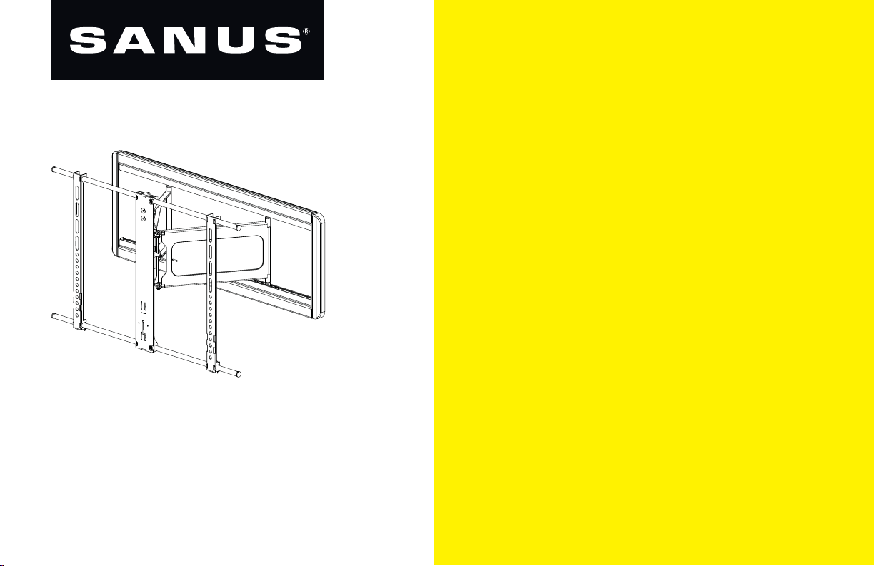
GET IT
RIGHT
THE FIRST TIME
Follow this step-by-step
VLF
INSTRUCTION MANUAL
613
instruction manual to
speed up your installation.
Page 2
WE’RE HERE TO HELP
Recommended placement
Want to watch a video that
shows how easy this DIY
project will be?
Watch it now at:
SANUS.com/2575
2
Get it right the first time.
HeightFinder™ shows you
where to drill.
Check it out at:
SANUS.com/1172
Our US-based install experts
are standing by to help.
Call us at:
800-359-5520
Or, chat at:
SANUS.com/chatSP
Page 3
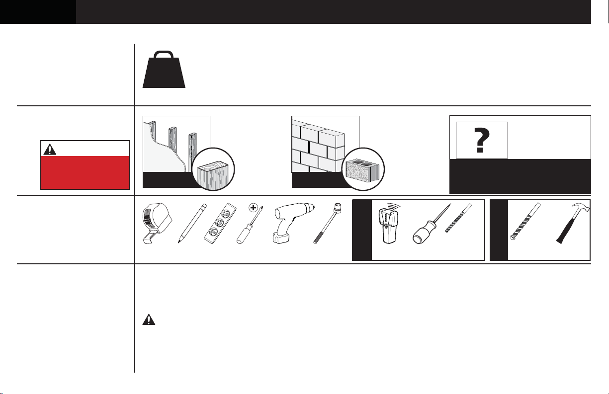
IMPORTANT SAFETY INSTRUCTIONS – SAVE THESE INSTRUCTIONS – PLEASE READ ENTIRE MANUAL PRIOR TO USE
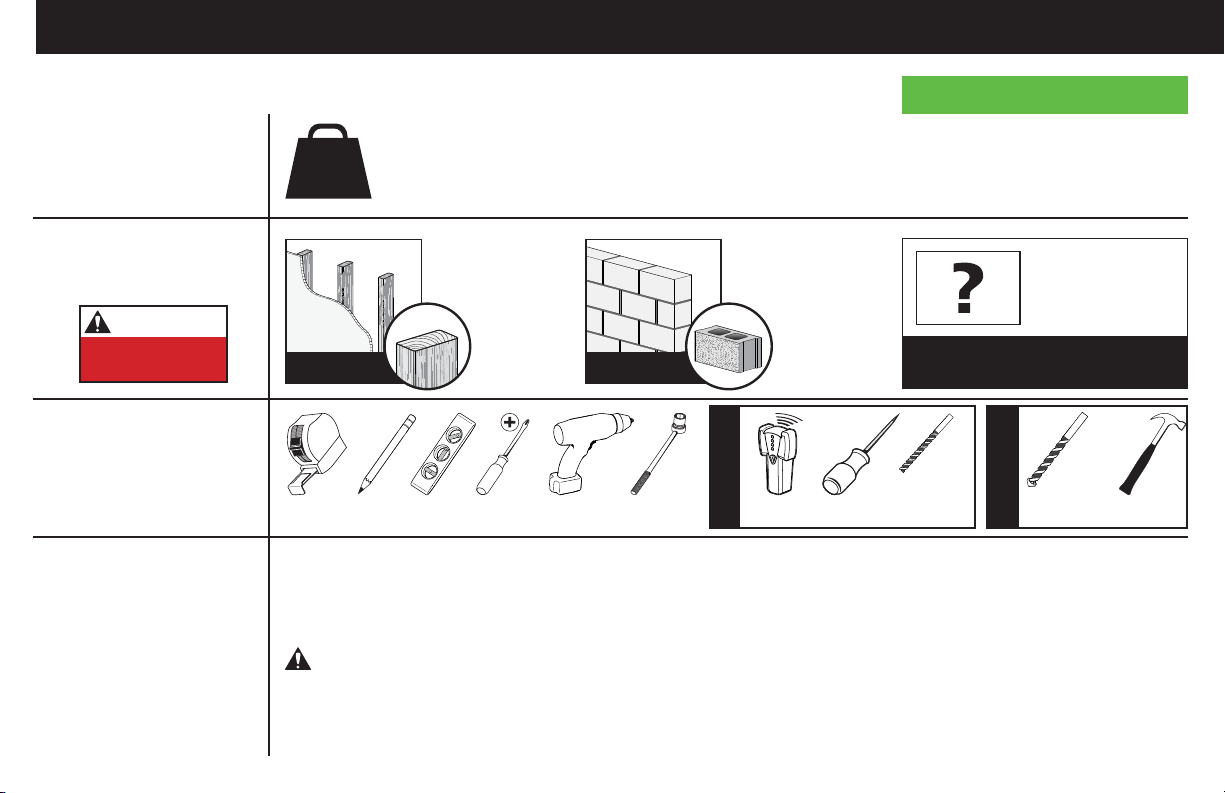
Before getting started, let’s make sure this mount is perfect for you!
Does your TV
1
(including accessories)
weigh MORE than
125 lbs. (56.6 kg)?
What is your
2
wall made of?
125 lbs.
(56.6 kg)
No — Perfect!
Yes — This mount is NOT compatible. Visit MountFinder.Sanus.com or call
1-800-359-5520 (UK: 0800-056-2853) to fi nd a compatible mount.
Drywall with
wood studs?
Solid concrete or
concrete block?
CAUTION:
DO NOT install
into drywall alone
Do you have
3
all the tools
needed?
Ready to
4
begin?
Perfect! Perfect!
1/2 in.
(13 mm)
Measure
Please read through these instructions completely to be sure you’re comfortable with this easy install process.
Also check your TV owner’s manual to see if there are any special requirements for mounting your TV.
If you do not understand these instructions or have doubts about the safety of the installation, assembly or use
of this product, contact Customer Service at 1-800-359-5520 (UK: 0800-056-2853).
Electric Drill Hammer
Socket
Wrench
Wood Stud Install
Para Español ver página 28
Unsure?
Call Customer Service:
1-800-359-5520 (UK: 0800-056-2853)
7/32 in.
(5.5 mm)
AwlPencil Level Stud FinderScrewdriverTape
Wood
Drill Bit
3/8 in.
(10 mm)
Concrete
Drill Bit
Concrete Install
CAUTION: Avoid potential personal injuries and property damage!
● This product is designed for use in wood stud, solid concrete, and concrete block walls - DO NOT install into drywall alone
● The wall must be capable of supporting fi ve times the weight of the TV and mount combined
● Do not use this product for any purpose not explicitly specifi ed by manufacturer
● Manufacturer is not responsible for damage or injury caused by incorrect assembly or use
3
Page 4
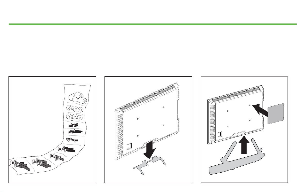
Before you begin
Don’t stress out when you see
all the hardware included.
Extra TV screw sizes and lengths
are provided to fi t most TVs.
RELAX!
You only use four
of the TV screws.
HARDWARE BAG
Remove the stand from your TV
— if attached.
Install any accessories
you may have purchased — if they
require the TV to be removed from the
wall for assembly. The TV is removable
for future accessory purchases.
4
Page 5
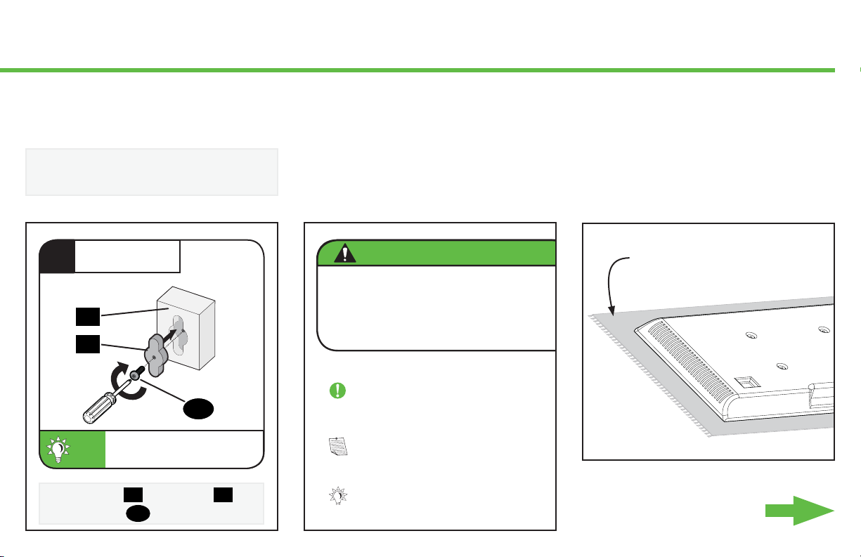
Step-by-Step illustrations
speed up your installation.
Don’t get it? Read the detailed
explanation below each step.
Read ALL CAUTION warnings.
These are IMPORTANT!
Protect the face of your TV
when laying it down for installation.
ASSEMBLE
1
Y
X
Each component has a number
TIP:
designation. See PAGE 6.
Secure part
using screw
X
to housing
S
.
S
CAUTION: Avoid potential
Read Important Stuff read read rea
Must Read read read read read read
Read read read Safety First read re
IMPORTANT: Read Important read
NOTE: Read read Dually Noted read
Y
TIP: Read That's Helpful read read
Soft clean surface
Let’s Go
5
Page 6
M8 x 25mm
M6 x 12mm
M6 x 35mm
M8 x 45mm
M8 x 50mm
M8 x 35mm
M8 x 16mm
M8 x 20mm
5mm 22mm
2.5mm
Attach TV Bracket to TVSTEP 1
WARNING:
and undamaged. If any parts are missing or damaged, do not return the damaged item to your dealer; contact Customer Service. Never use damaged parts!
NOTE: Not all hardware included will be used.
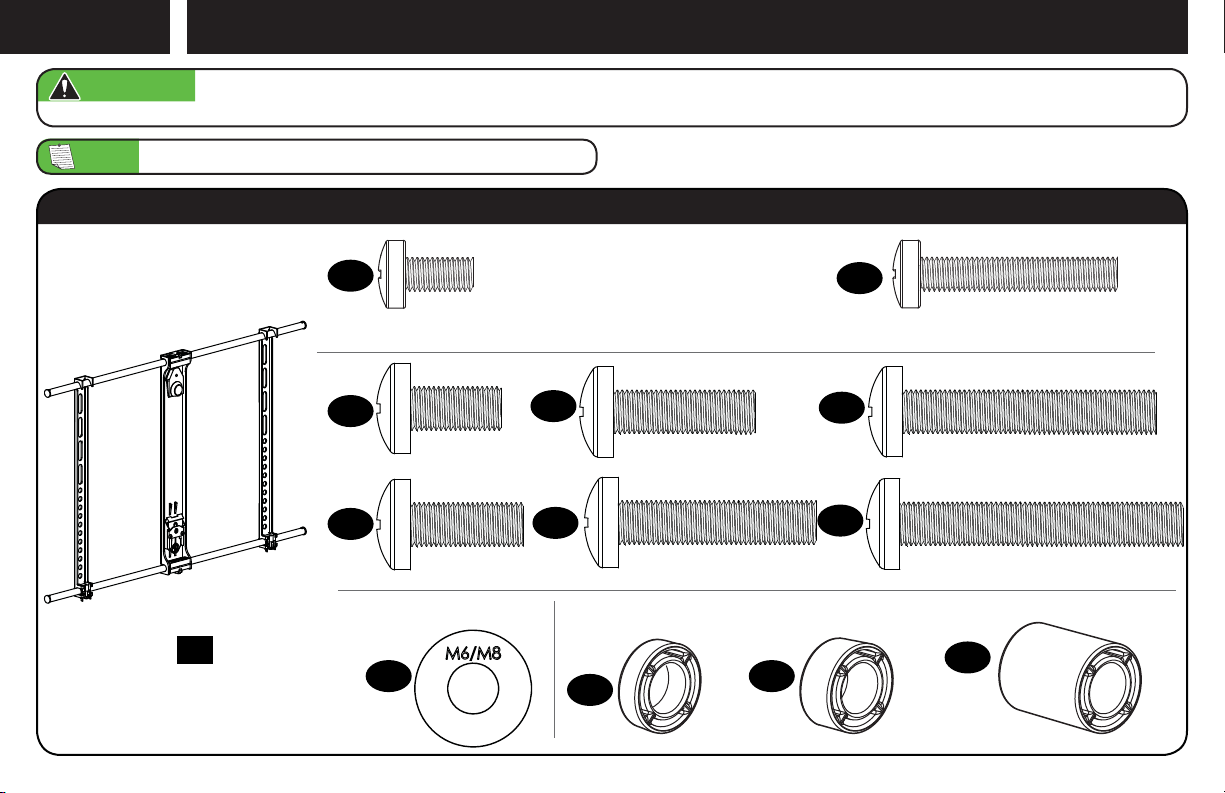
This product contains small items that could be a choking hazard if swallowed. Before starting assembly, verify all parts are included
Parts and Hardware for STEP 1
TV Bracket
01
x1
02
x4
03
x4
TV Screws M8 TV Screws M6
04
x4
10
x4
TV Washers
05
x4
06
x4
11
x4
12
x4
07
x4
08
x4
09
x4
Spacers
13
x4
6
Page 7
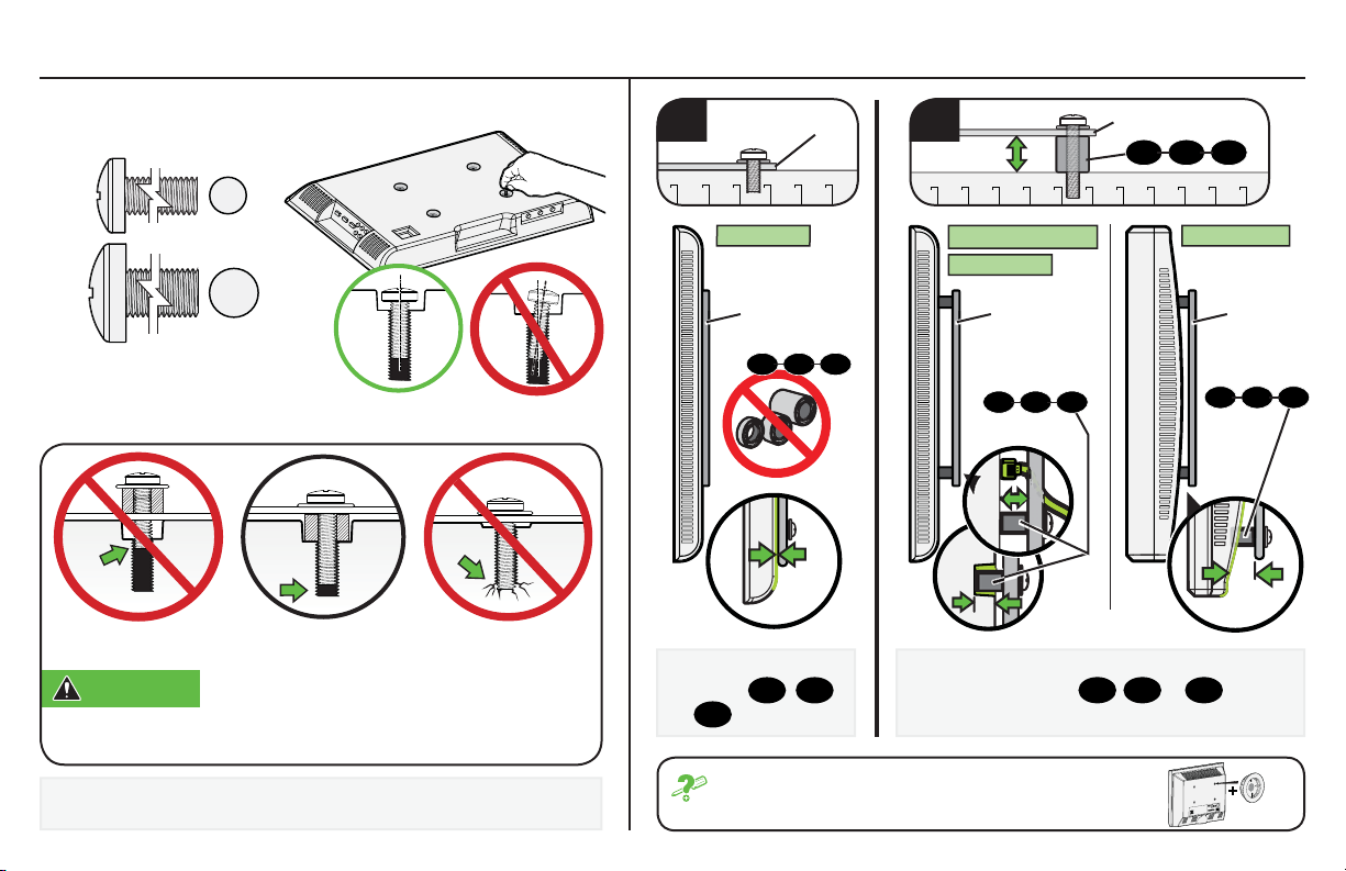
1.1 Select TV Screws
1.2 Spacer Determination
M6
M8
Too Short Correct Too Long
CAUTION: Verify adequate thread engagement with your
screw/washer/spacer combination AND the TV bracket. (STEP 1.2).
TOO SHORT will not hold the TV and TOO LONG will damage the TV.
a
Flat Back
For
flat-back TVs,
spacers
13
or
TV Bracket
TV Bracket TV Bracket TV Bracket
1211 13
no
11
12
,
are required.
b
Cable Interference
Inset Holes
1211 13
For rounded-back TVs, cable interference or
inset holes, spacers
extra space between the TV and TV bracket.
TV Bracket
11
,
12 or
1211 13
Round Back
13
to create
1211 13
Determine which screw diameter (M6 or M8) fits the four
mounting holes on the back of your TV.
If your TV included inset spacers or wall mount
adapters, see Troubleshooting on PAGE 27.
7
Page 8
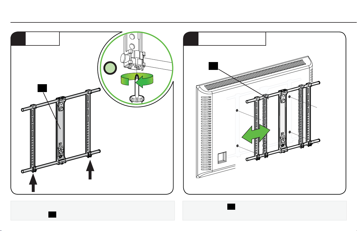
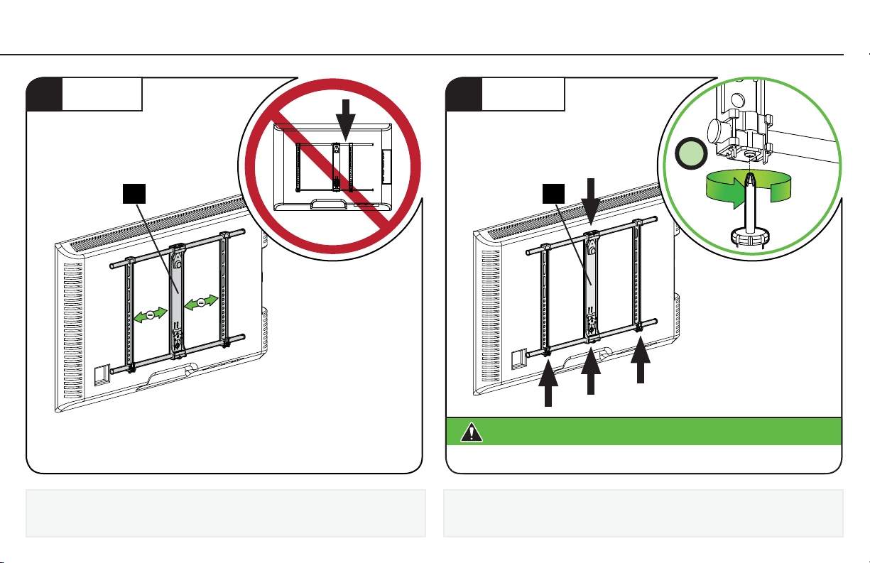
1.3 Assemble TV Bracket
LOOSEN
1
2X
01
Loosen the two lower fasteners enough to slide the outer columns
on TV bracket
8
01
(Indicated with arrows).
.
ADJUST TO FIT TV
2
01
Adjust TV bracket 01 to line up with your TV's mounting hole pattern.
Page 9
3
CENTER
TIGHTEN
4
01 01
CAUTION:
Do not overtighten the fasteners. Tighten only until snug.
4X
Avoid potential personal injury or property damage!
Be sure the center column is evenly spaced between the outer columns.
Tighten the two lower fasteners, and verify the two middle lower/
upper fasteners are tightened. (Indicated with arrows).
9
Page 10
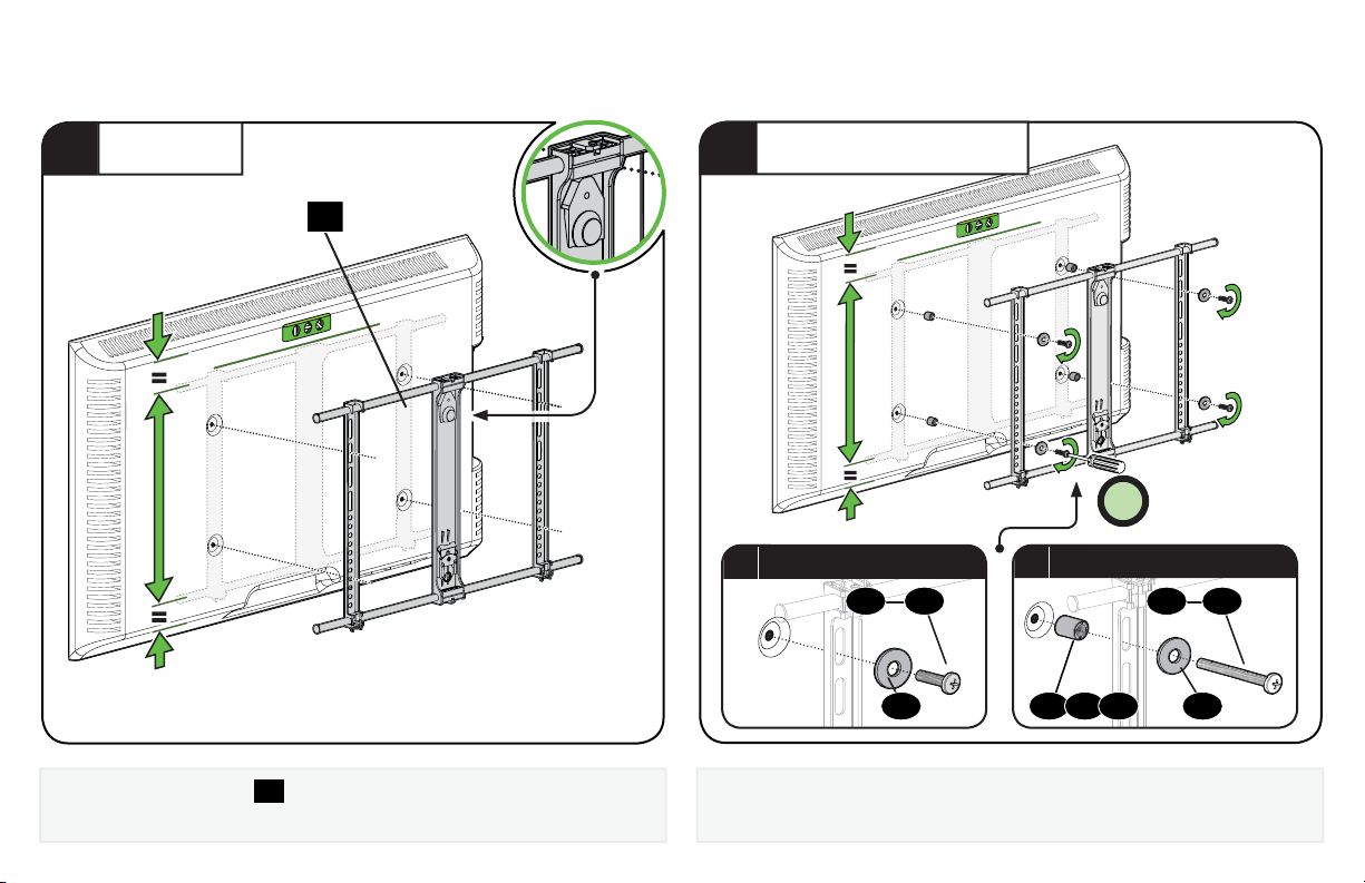
1.4 Attach TV Bracket Assembly to TV
POSITION
1
01
Top of TV
Center the TV bracket
making sure the bracket is level. Note the orientation of the bracket.
10
01
over your TV hole pattern as shown,
SECURELY TIGHTEN
2
4X
Flat-back TVs
a
Install using the spacer, screw and washer combination you
selected for your TV.
Rounded-back TVs / Extra Space
b
0202 0909
11 12 1310 10
Page 11
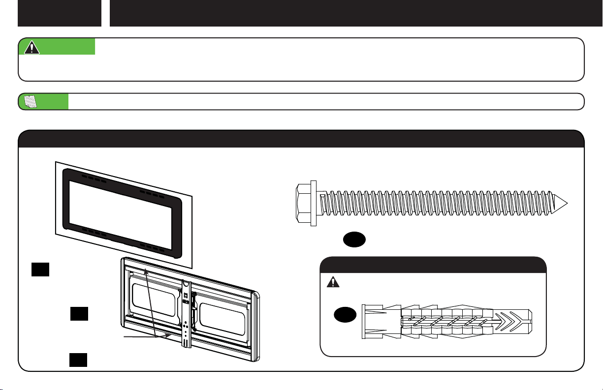
STEP 2
Attach Wall Plate to Wall
WARNING:
included and undamaged. If any parts are missing or damaged, do not return the damaged item to your dealer; contact Customer Service.
Never use damaged parts!
NOTE: Not all hardware included will be used.
This product contains small items that could be a choking hazard if swallowed. Before starting assembly, verify all parts are
Parts and Hardware for STEP 2
Lag Bolt
5⁄16 in. x 3 ½ in.
x4
Wall Plate
Template
x1
14
Wall Plate /
Arm Assembly
Wall Plate Cover
x1
15
(Attached)
x2
16
17
For concrete installations ONLY
CAUTION: Do not use in drywall or wood
Concrete Anchor
18
x4
Fischer UX10 x 60R
11
Page 12
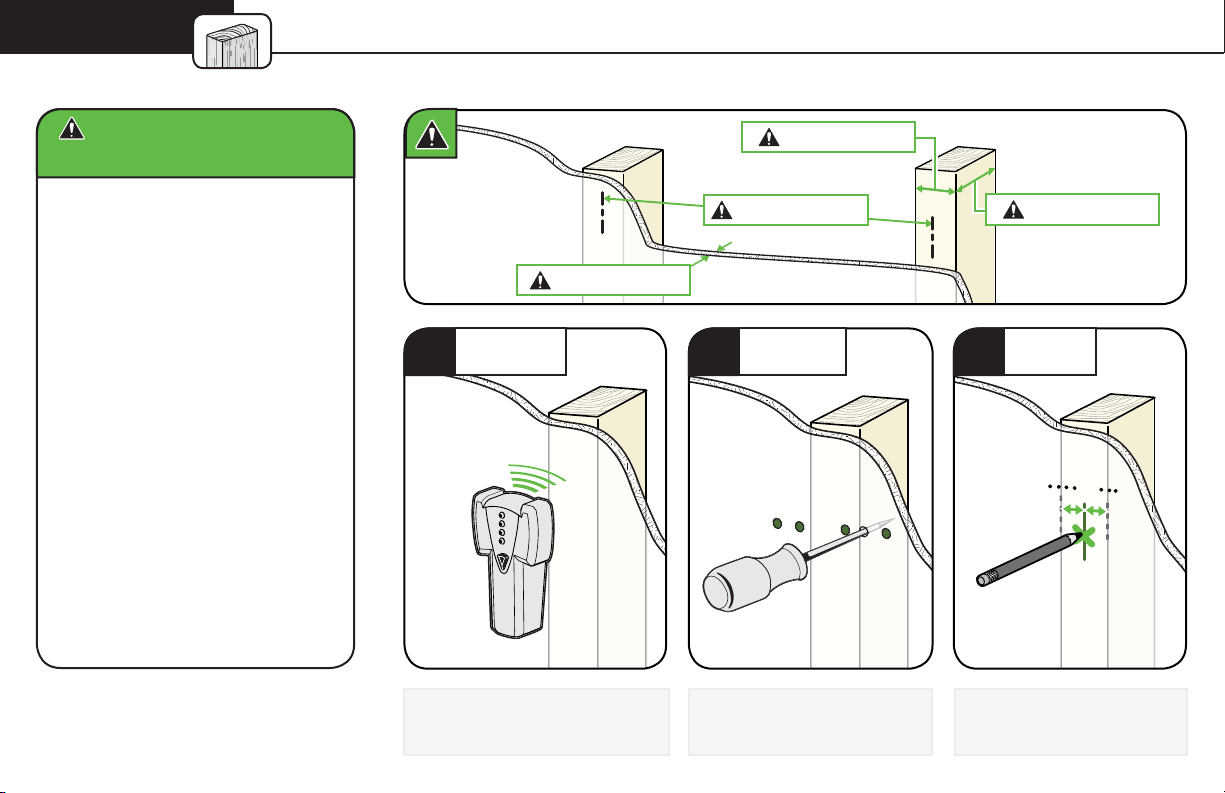
STEP 2A Wood Stud Installation
CAUTION: Avoid potential
personal injury or property damage!
● Drywall covering the wall
must not exceed 5/8 in. (1.5 cm)
● Minimum wood stud size:
nominal 2 x 4 in. (5.1 x 10.2 cm)
actual 1 ½ x 3 ½ in. (3.8 x 8.9 cm)
● Minimum horizontal space
between fasteners:16 in. (40.6 cm)
● Stud centers must be verifi ed
12
Max. 5/8 in. (1.5 cm)
LOCATE
1
Locate the studs using a
stud finder.
Min. 1 ½ in. (3.8 cm)
Min. 16 in. (40.6 cm)
VERIFY
2
Find the edges of the studs
using an awl or small drill bit.
Min. 3 ½ in. (8.9 cm)
MARK
3
Mark the centers of the
studs with a pencil.
Page 13
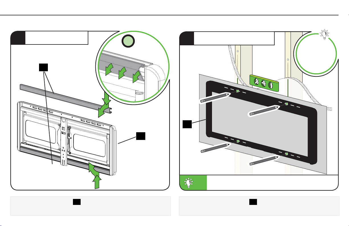
REMOVE COVERS
4
16
2X
15
POSITION TEMPLATE
5
14
To calculate your precise wall plate location, check out
TIP:
our HeightFinder at sanus.com [www.sanus.com/1172].
Visit
HeightFinder™
sanus.com
/1172
Remove wall plate covers
while pulling the cover forward.
16
by pushing the outer edge inward,
Place the wall plate template 14 at your desired height and position
the slotted holes over your stud center lines. Level and tape in place.
13
Page 14
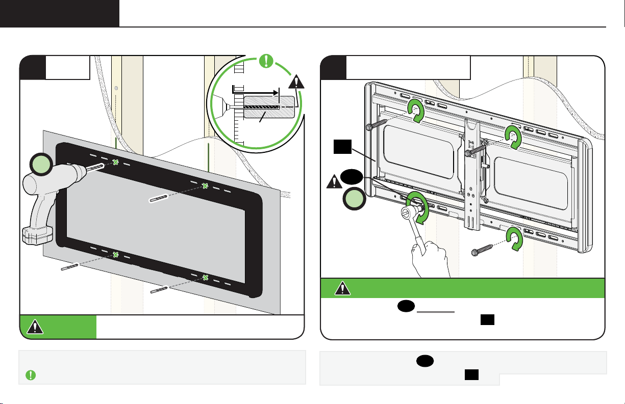
STEP 2A (continued)
DRILL
6
4X
CAUTION:
Drill the four pilot holes using a 7/32 in. (5.5 mm) diameter drill bit.
IMPORTANT: Pilot holes must be drilled to a depth of 3 ½ in. (8.9 cm).
14
Be sure you drill into the CENTER of the stud.
3 ½ in. (8.9 cm)
7/32 in.
(5.5 mm)
SECURELY TIGHTEN
7
15
17
4X
CAUTION:
All four lag bolts
unwanted movement of the wall plate
securely fastened to the wall before continuing on to the next step.
Install the four lag bolts 17 and firmly tighten until they are pulled flush
against the wall plate/arm assembly
Avoid potential personal injury or property damage!
MUST BE firmly tightened to prevent
17
Ensure the wall plate is
15.
15
.
Go to STEP 3 on PAGE 18.
Page 15
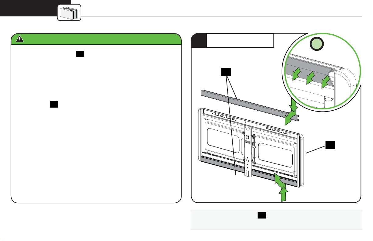
STEP 2B
CAUTION: Avoid potential personal injury or property damage!
● Mount the wall plate
● Minimum solid concrete thickness: 8 in. (20.3 cm)
● Minimum concrete block size: 8 x 8 x 16 in. (20.3 x 20.3 x 40.6 cm)
● Minimum horizontal space between fasteners: 24 in. (61.0 cm)
Solid Concrete or Concrete Block Installation
15
directly onto the concrete surface
REMOVE COVERS
1
16
2X
● For Concrete applications, the arm assembly of wall plate/arm
assembly
this in mind when selecting the wall plate location.
15
must remain centered in the wall plate. Keep
Remove wall plate covers
while pulling the cover forward.
16
by pushing the outer edge inward,
15
15
Page 16
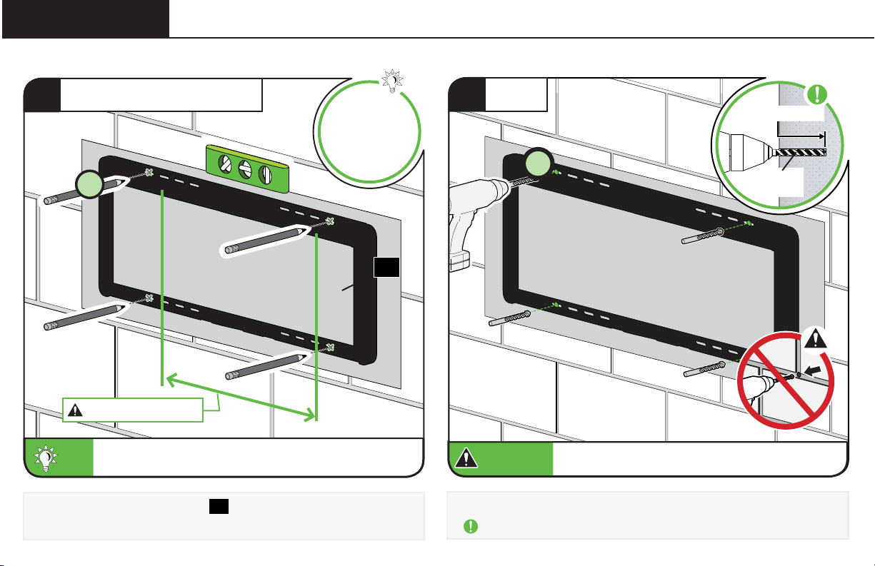
STEP 2B (continued)
POSITION TEMPLATE
2
Visit
HeightFinder™
sanus.com
/1172
4X
Min. 24 in. (61.0 cm)
To calculate your precise wall plate location, check out
TIP:
TIP:
our HeightFinder at sanus.com [www.sanus.com/1172].
Position the wall plate template 14 on the wall at your desired height.
Level and tape in place.
16
.
14
DRILL
3
4X
CAUTION:
CAUTION:
Drill four pilot holes using a 3/8 in. (10 mm) diameter drill bit.
IMPORTANT: Pilot holes must be drilled to a depth of 3 ¾ in. (9.5 cm).
Never drill into the mortar between blocks.
Never drill into the mortar between blocks.
3 ¾ in. (9.5 cm)
3/8 in.
(10 mm)
Page 17
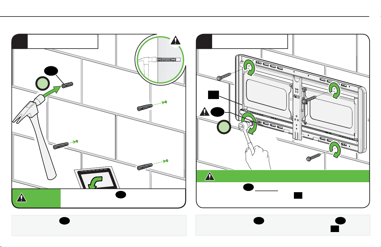
INSERT ANCHORS
34
18
4X
CAUTION:
CAUTION:
Be sure the anchors
with the concrete surface.
14
18
are seated fl ush
SECURELY TIGHTEN
5
15
17
4X
CAUTION:
All four lag bolts
unwanted movement of the wall plate
securely fastened to the wall before continuing on to the next step.
Avoid potential personal injury or property damage!
MUST BE firmly tightened to prevent
17
Ensure the wall plate is
15.
Insert four anchors
18
.
Install the four lag bolts 17. Firmly tighten all four lag bolts 17 until
they are pulled flush against the wall plate/arm assembly
15
.
17
Page 18
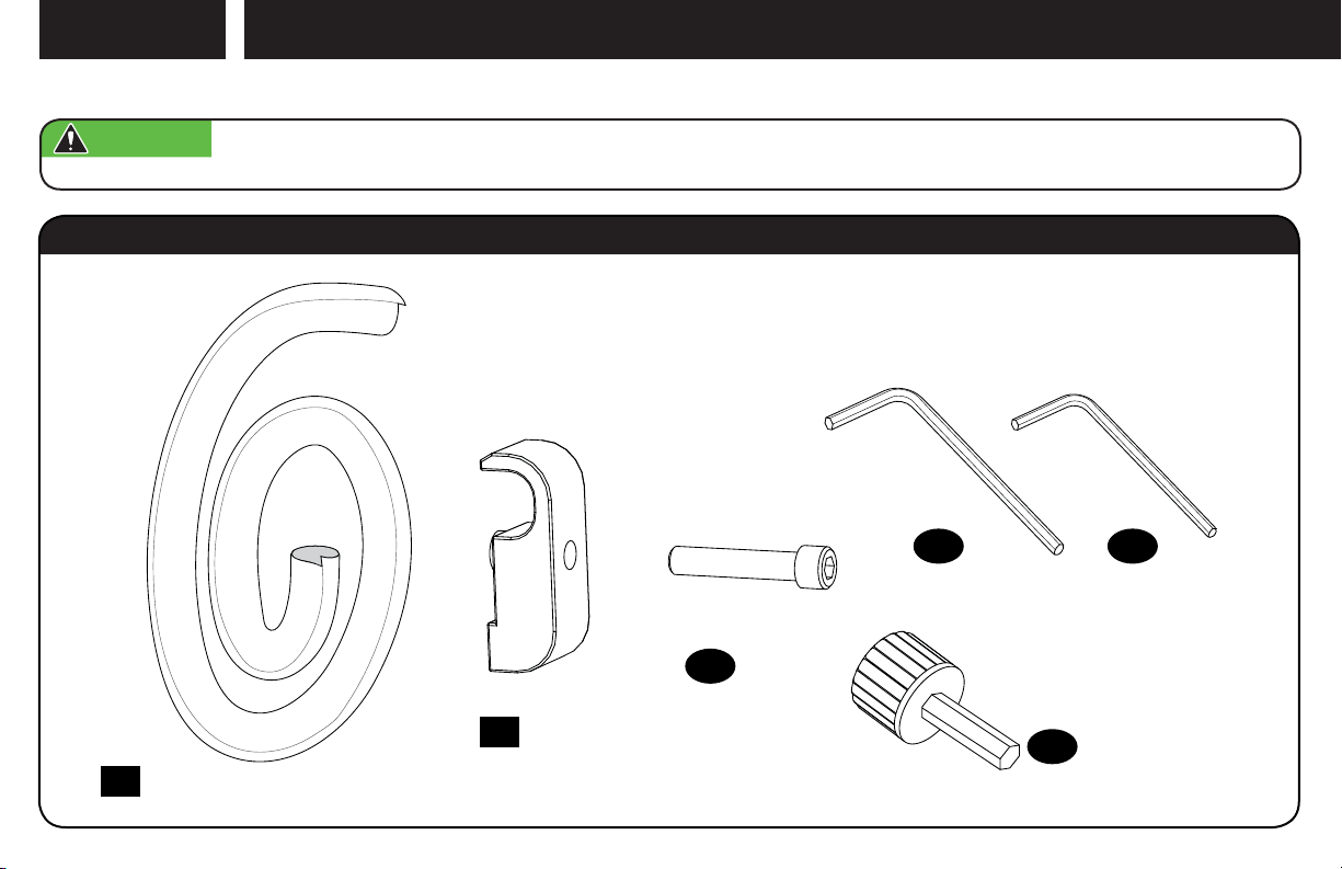
STEP 3
WARNING: Before starting assembly, verify this part is undamaged. If damaged, do not return the damaged item to your dealer; contact
Customer Service. Never use damaged parts!
Attach TV to Wall Plate
Parts and Hardware for STEP 3
3/16 in. 5/32 in.
Hex Key Hex Key
Cable Sleeve
x1
19
Cable Holder
x1
20
Securement Screw
(Cable Holder)
21
x1
22
x1
3/16 in. Hex
Knob Tool
23
x1
24
x1
18
Page 19
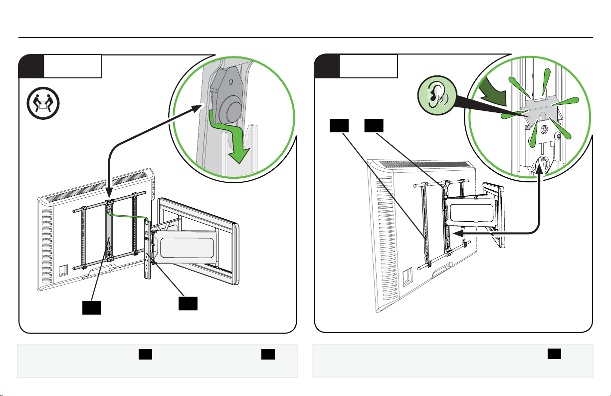
3.1 Hang Your TV
HANG
1
HEAVY! You may
need assistance
with this step.
01
Hang the TV/Bracket assembly 01 onto wall plate/arm assembly
15
ATTACH
2
1501
15
.
Press the bottom of the TV into the wall plate/arm assembly
you hear the lock click, securing the TV in place.
15
until
19
Page 20
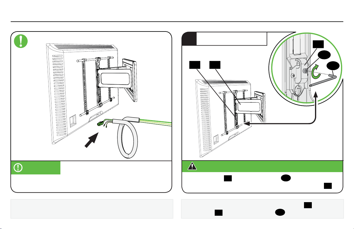
3.1 (continued)
SECURELY TIGHTEN
3
20
21
IMPORTANT:
Skip STEP 3 and proceed to SECTION 3.2 on PAGE 21.
Otherwise you MUST proceed with STEP 3 on the right.
To secure your cables using the cable system, go to PAGE 21 now.
If skipping the cable system, you MUST complete STEP 3 on the right.
20
For cable management:
1501
CAUTION:
The cable holder 20 and securement screw 21 MUST be in place and
tightened, to securely fasten the TV to the wall plate/arm assembly
To lock the TV in place on wall plate/arm assembly
cable holder
Avoid potential personal injury or property damage!
15
20
and securement screw
21
as shown.
15
, install the
22
.
Page 21
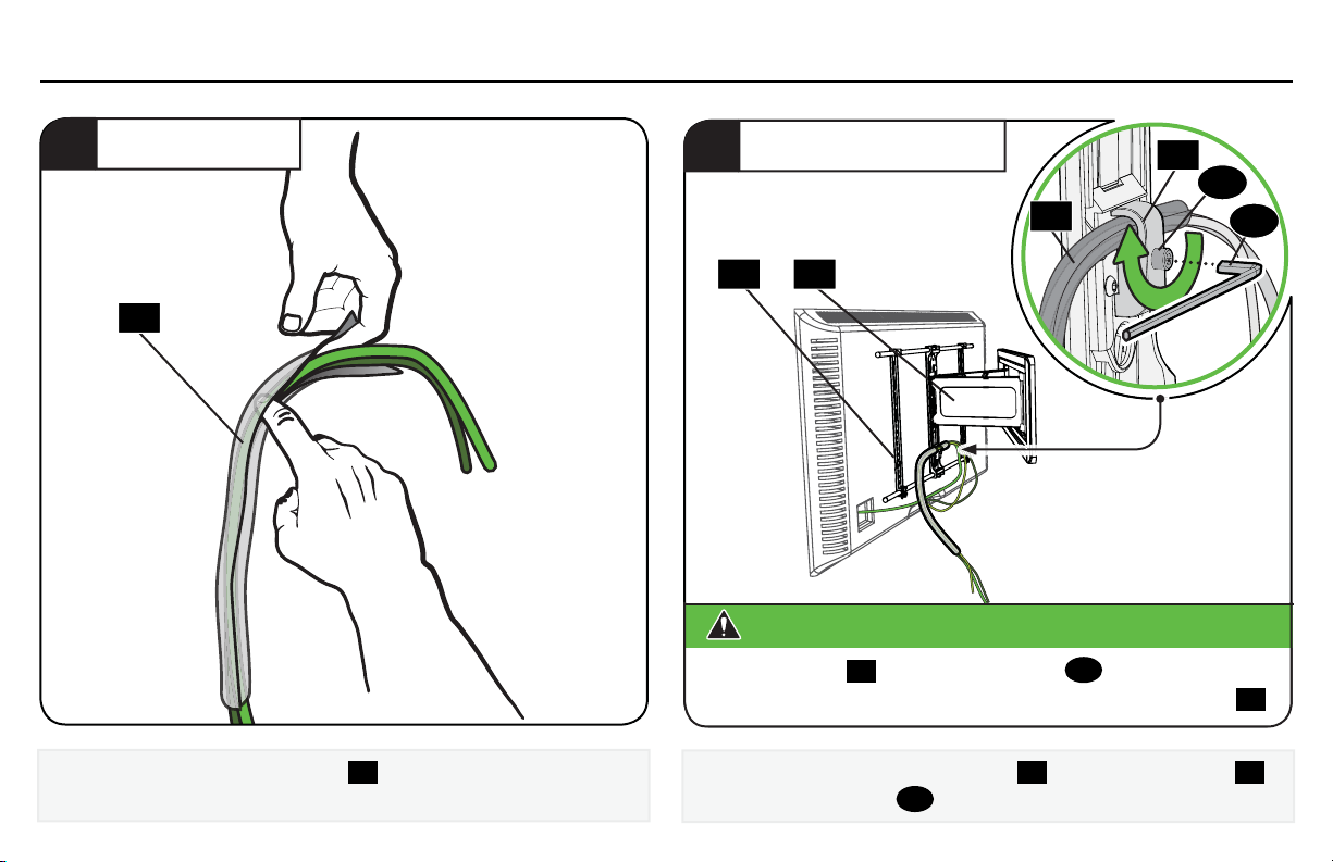
3.2 Manage Cables
WRAP CABLES
1
19
Slip your cables into cable sleeve 19.
SECURELY TIGHTEN
2
20
21
19
1501
CAUTION:
The cable holder 18 and securement screw 19 MUST be in place and
tightened, to securely fasten the TV to the wall plate/arm assembly
Secure the cables and cable sleeve
and securement screw
Avoid potential personal injury or property damage!
19
with the cable holder
,
21
as shown.
22
12
20
.
21
Page 22
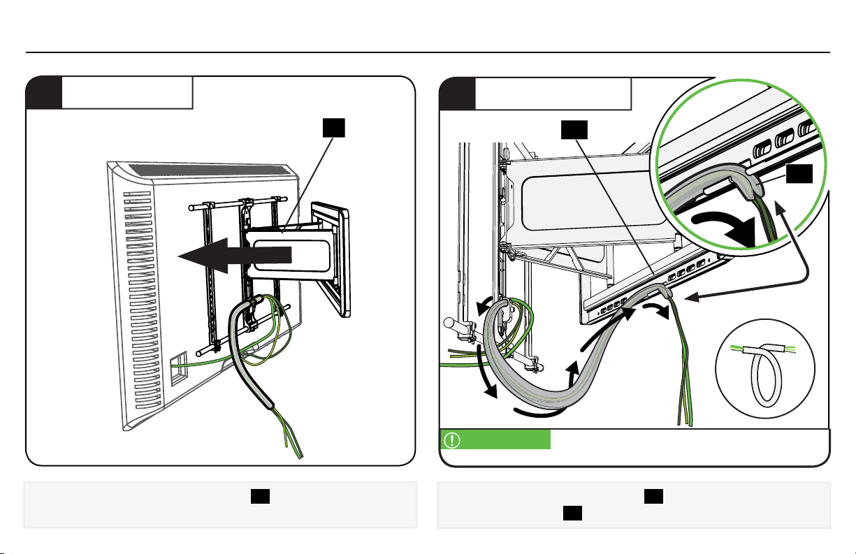
3.2 (continued)
EXTEND ARMS
3
15
Pull the arms of wall plate/arm assembly
enough slack and prevent stretching the cables when the TV is moved.
22
15
to full extension, to leave
POSITION CABLES
4
15
IMPORTANT: Curve the cable sleeve into a coil shape as shown —
TIP:
to allow the cables to curl up when the TV is retracted.
Insert the free end of cable sleeve
plate/arm assembly
15.
19
into the channels of wall
19
Page 23
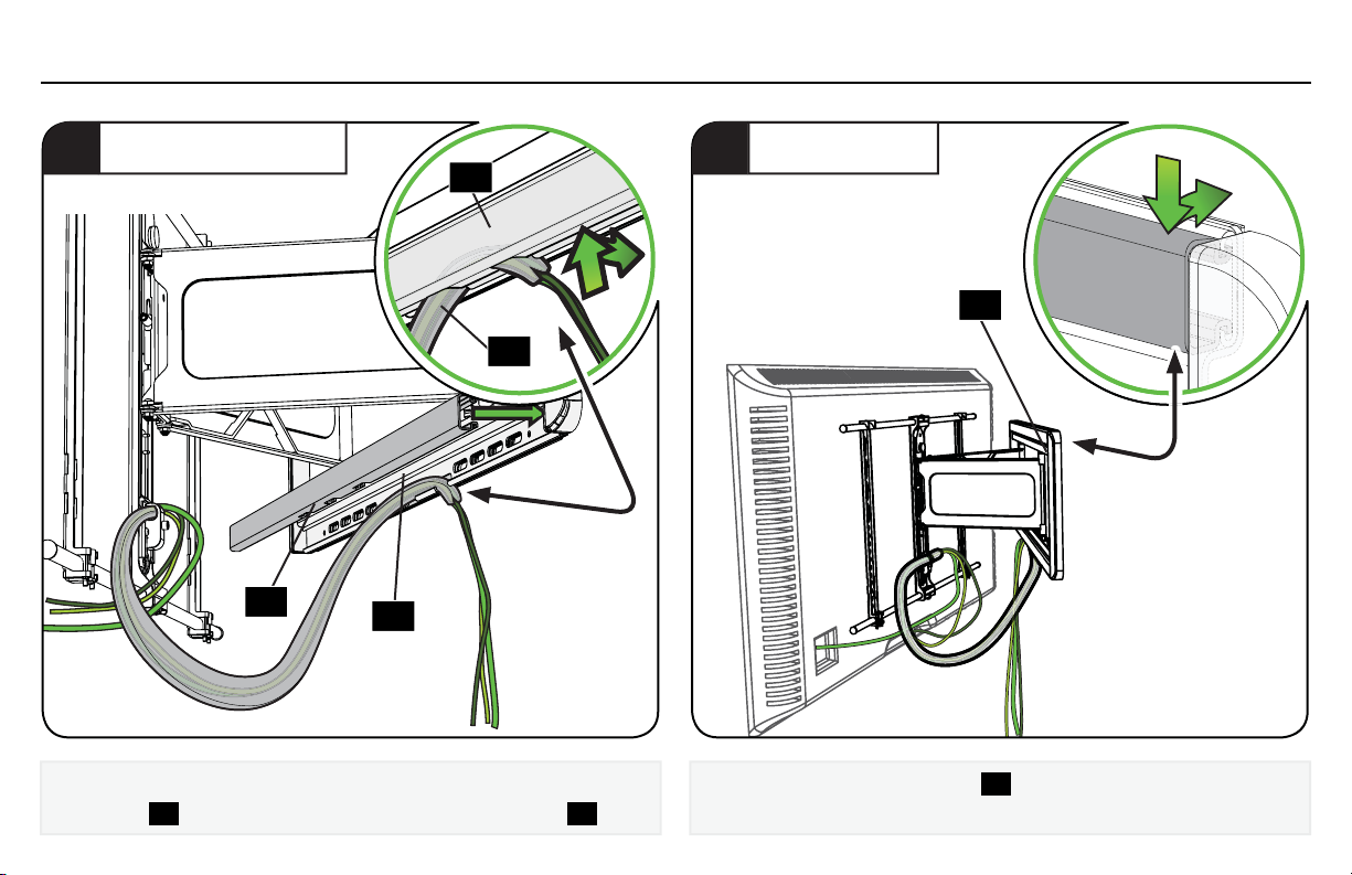
3.3 Install Cover Strips
INSTALL BOTTOM
1
16
Secure the cables onto the bottom channel of wall plate/arm
assembly
15
, by snapping in the bottom wall plate cover 16.
15
16
19
INSTALL TOP
2
Install the top wall plate cover
16
16
.
23
Page 24
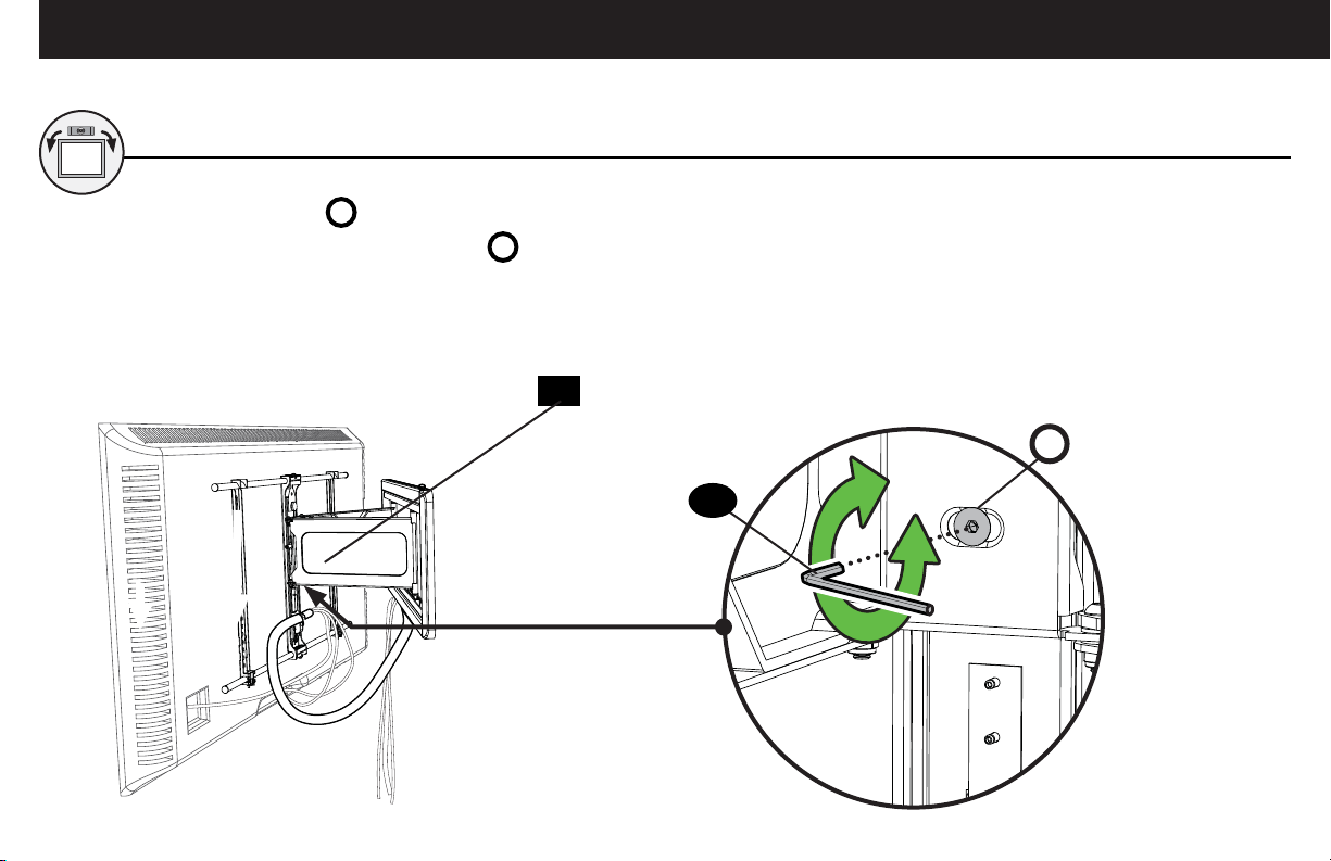
Adjustments
LEVEL
Loosen leveling screw
Level your TV, then tighten leveling screw L.
L.
15
L
24
24
Page 25
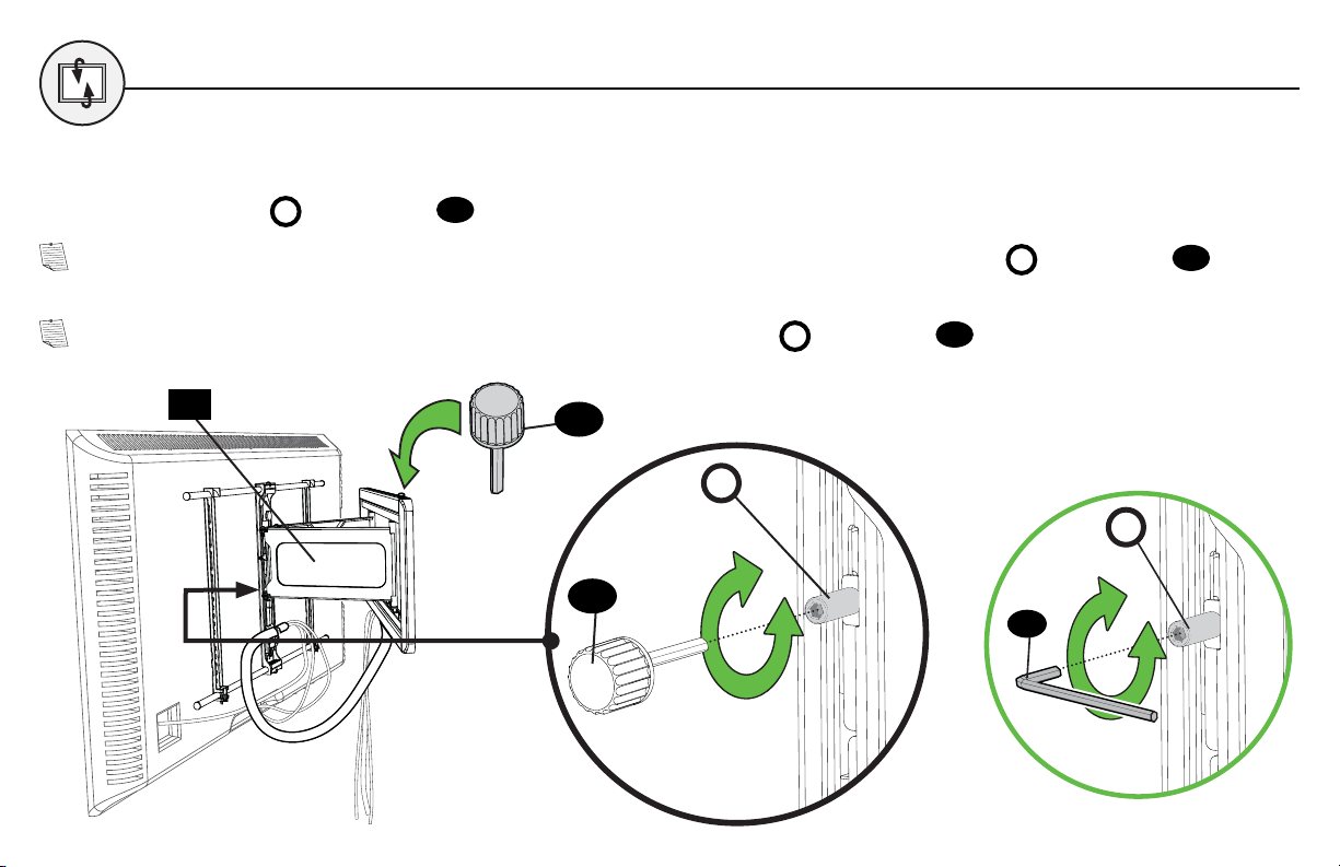
TILT
Your TV should adjust easily when moved, then stay in place.
Adjust the tilt tension knob
using knob tool
T
23
if your TV naturally tilts up or down.
NOTE: If you do not intend to adjust the tilt for different viewing locations, you can tighten the tilt tension knob
to prevent unwanted movement.
NOTE: If needed for additional tightening, you may also tighten the tilt tension knob
15
23
using hex key
T
T
23
22
T
.
22
using knob tool
T
23
25
Page 26
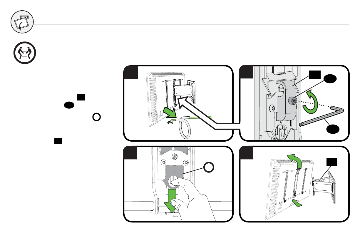
REMOVING THE TV
HEAVY! You may need
assistance with this step.
1. Disconnect all cables from the TV.
21
20
and
.
2. Remove the cable holder
securement screw
3. Pull down on the Release ring
to release the TV.
4. Carefully lift the TV from wall plate/
arm assembly
26
15.
R
1
2
3 4
R
20
21
22
15
Page 27
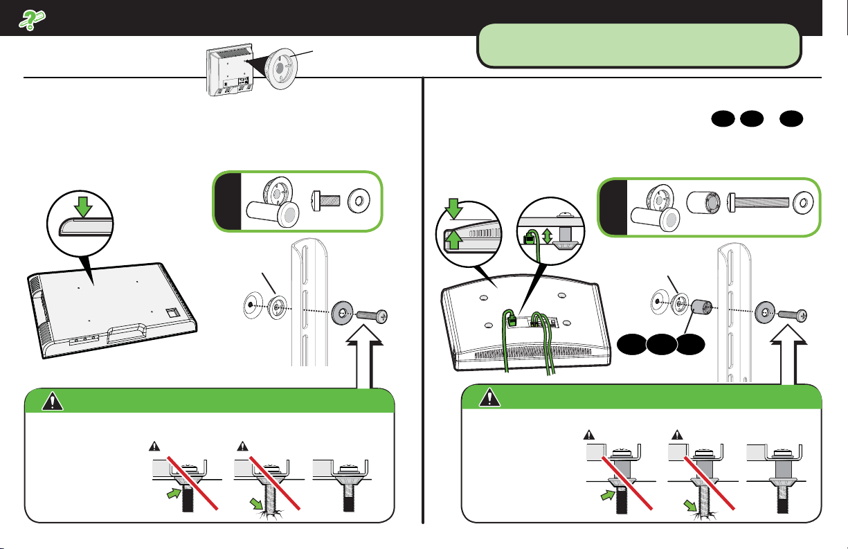
Troubleshooting
TV supplied spacers
TV Supplied
Spacers
If you are uncertain about your hardware selection,
contact Customer Service at 1-800-359-5520
a: Use your TV supplied spacer/adapter for flat back TVs (AND
you want your TV closer to the wall).
FLAT BACK
a
TV Supplied
Spacer/adapter
CAUTION:
Use the correct screw length for adequate thread engagment.
– Too short will
not hold the TV.
– Too long will
damage the TV.
Avoid potential injury or property damage!
Too Short
Too Long
Correct
b: Use your TV supplied spacer/adapter and spacer
● Round (irregular) back TVs
ROUND BACK CABLES
● Extra space needed for cables
11
b
TV Supplied
Spacer/adapter
11 1312
CAUTION:
Use the correct screw length for adequate thread engagment.
– Too short will
not hold the TV.
– Too long will
damage the TV.
Avoid potential injury or property damage!
Too Short
Too Long
12 or
,
13
Correct
for:
27
Page 28
Español
CONSERVE ESTAS INSTRUCCIONES DE SEGURIDAD IMPORTANTES Y LEA TODO EL MANUAL ANTES DE UTILIZAR ESTE PRODUCTO.
Antes de comenzar, verifi quemos si este soporte es el adecuado para usted.
¿Su televisor
1
(incluidos los
accesorios)
MÁS de 56,6 kg
(125 lb)?
pesa
56,6 kg
(125 lb)
No. ¡Perfecto!
Sí. Este soporte NO es compatible. Visite MountFinder.Sanus.com o llame al 1-800-359-5520
(Reino Unido: 0800-056-2853) para encontrar un soporte compatible.
¿De qué está
2
hecha su pared?
PRECAUCIÓN:
NO lo instale en
tabiques únicamente
de yeso
¡Perfecto! ¡Perfecto!
¿Tabiques de yeso
con montantes de
madera?
¿Hormigón sólido o
bloques de hormigón?
¿No está seguro?
Llame al servicio de atención al
cliente: 1-800-359-5520
(Reino Unido: 0800-056-2853)
¿Tiene todas
3
las herramientas
necesarias?
¿Listo para
4
comenzar?
Llave de
métrica
Lea estas instrucciones en su totalidad para sentirse seguro y cómodo con este fácil proceso de instalación. Consulte igualmente
el manual del usuario de su televisor para saber si existe algún requisito especial para instalar su televisor en la pared.
Si no entiende las instrucciones o si tiene dudas acerca de la seguridad de la instalación, del ensamblado o del uso del producto,
póngase en contacto con el servicio de atención al cliente al 1-800-359-5520 (Reino Unido: 0800-056-2853).
DestornilladorCinta
Taladro
eléctrico
tubo de
13 mm
(1/2 pulg.)
Instalación en
Localizador
de montantes
montantes de madera
PunzónLápiz Nivel
Broca para
madera
de 5,5 mm
(7/32 pulg.)
Broca para
hormigón
hormigón
de 10 mm
Instalación en
(3/8 pulg.)
Martillo
PRECAUCIÓN: Evite posibles lesiones personales y daños materiales.
● Este producto está diseñado para usarse únicamente en aplicaciones con montantes de madera, hormigón y bloques de
hormigón. NO lo instale en tabiques únicamente de yeso
● La pared debe soportar cinco veces el peso del televisor y del soporte juntos
● No utilice este producto para ningún otro propósito que no sea el explícitamente especifi cado por el fabricante
28
● El fabricante no se responsabiliza por ningún daño o lesión resultante del montaje incorrecto o de uso indebido
Page 29
Español
ESTAMOS AQUÍ PARA AYUDAR
¿Quiere ver un video donde se muestra lo fácil que va a ser seguir estos pasos?
Véalo ahora en: SANUS.com/2575
Acierte a la primera. HeightFinder™ le indica el lugar donde debe taladrar.
Descúbralo en: SANUS.com/1172
Nuestros expertos en instalación de EE. UU. están listos para ayudar.
Llámenos al: 800-359-5520 O contacte con nosotros por chat en: SANUS.com/chatSP
Antes de comenzar
No se estrese cuando vea todas las piezas que se incluyen. Se proporcionan tornillos específi cos de diferentes tamaños y longitudes para
poder usarlos con la mayoría de televisores.
Retire el soporte de su televisor... ¡si ya lo tenía instalado claro!
Instale todos los accesorios que quiera añadir a su televisor.
Compruebe en los manuales de los accesorios si es necesario instalarlos ANTES de montar el televisor.
Utilice solo las ilustraciones para instalar el soporte del televisor.
¿No lo entiende? Lea la explicación detallada debajo de cada paso.
Lea TODAS las advertencias de seguridad. ¡Son muy IMPORTANTES! [ PRECAUCIÓN: IMPORTANTE: NOTA: CONSEJO: ]
Proteja la pantalla del televisor cuando lo ponga boca abajo para la instalación.
¡RELÁJESE! Solamente tendrá que usar cuatro de estos tornillos para el televisor.
PÁGINA 6
Fijar el soporte al televisorPASO 1
ADVERTENCIA: Este producto contiene piezas pequeñas que, en caso de ser tragadas, podrían producir asfixia. Antes de iniciar el ensamblaje, compruebe que todas
las piezas estén incluidas y en buenas condiciones. Si faltan piezas o alguna está dañada, no devuelva el artículo al distribuidor. Póngase en contacto con el servicio de
atención al cliente. Nunca utilice piezas deterioradas.
NOTA: No todos los elementos de sujeción incluidos deberán utilizarse.
29
Page 30
Español
1.1 Seleccione los tornillos del televisor
PRECAUCIÓN: Compruebe el enrosque adecuado de la combinación tornillo/arandela/espaciador y los soportes del televisor. (PASO 1.3).
Si el tornillo es DEMASIADO CORTO, no sostendrá el televisor. Si es DEMASIADO LARGO, el televisor se dañará.
Determine qué diámetro de tornillos (M6 o M8) encaja en los cuatro orificios de montaje de la parte trasera de su televisor.
1.2. Determine el espaciador que necesita para su tipo de televisor
Determine dónde desea colocar el espaciador cuando fije el soporte del televisor en el PASO 1.3.
Para los televisores con la parte trasera plana y para que su televisor esté más cerca de la pared, utilice tornillos más cortos sin espaciador. Para los televisores con la parte trasera
redondeada, interferencia de cables u orificios intercalados, utilice tornillos más largos y espaciadores 11 12 o 13 para crear espacio adicional entre el televisor y el soporte.
1.3 Arme el soporte del televisor
1
AFLOJAR
Afloje los dos elementos de sujeción superiores y los dos inferiores del soporte del televisor 01. (Se indica con flechas).
2
AJUSTAR
Ajuste el soporte del televisor 01 para alinearlo con el patrón de orificios del montante del televisor.
3
CENTRAR
Asegúrese de que la columna central es equidistante de las otras dos columnas.
4
APRETAR
Apriete los elementos de sujeción superior e inferior y compruebe que los de la parte central también están bien apretados. (Se indica con flechas).
1.4 Fije las placas de sujeción al televisor
1
COLOCAR
Centre el soporte del televisor 01 sobre el patrón de orificios del aparato tal y como se muestra y asegúrese de que el soporte quede nivelado. Tome nota de la orientación del
soporte.
2
APRETAR CON FIRMEZA
Haga la instalación utilizando la combinación de espaciadores, tornillos y arandelas que seleccionó para su televisor.
Fijar la placa mural a la paredPASO 2
ADVERTENCIA: Este producto contiene piezas pequeñas que, en caso de ser tragadas, podrían producir asfixia. Antes de iniciar el ensamblaje, compruebe que todas las
piezas estén incluidas y en buenas condiciones. Si faltan piezas o alguna está dañada, no devuelva el artículo al distribuidor. Póngase en contacto con el servicio de atención al
cliente. Nunca utilice piezas deterioradas.
NOTA: No todos los elementos de sujeción incluidos deberán utilizarse.
PÁGINA 11v
PASO 2A
PRECAUCIÓN: Evite posibles lesiones físicas y daños materiales
● El yeso que recubre la pared no debe exceder los 1,5 cm (5/8 pulg.)
● Tamaño mínimo del montante de madera: común 5,1 x 10,2 cm (2 x 4 pulg.) nominal 3,8 x 8,9 cm (1 ½ x 3 ½ pulg.)
● Espacio horizontal mínimo entre los elementos de sujeción: 40,6 cm (16 pulg.)
● Debe comprobar los montantes centrales
30
Instalación en pared con montantes de madera
PÁGINA 12
Page 31
1
LOCALIZAR
Localice los montantes usando un localizador de montantes.
2
COMPROBAR
Encuentre los bordes de los montantes usando un punzón o una pequeña broca.
3
MARCAR
Marque los centros de los montantes con un lápiz.
4
COLOCAR LA PLANTILLA
CONSEJO: Para calcular la ubicación concreta de la placa mural, pruebe nuestra herramienta HeightFinder disponible en sanus.com [www.sanus.com/1172].
Coloque la plantilla de la placa mural
5
TALADRAR LOS ORIFICIOS
Taladre los cuatro orificios guía con una broca de 5,5 mm (7/32 pulg.) de diámetro.
(3 ½ pulg.). Retire la plantilla de la placa mural
6
RETIRAR LAS CUBIERTAS
Retire las cubiertas de la placa mural 16 apretando hacia abajo el borde superior mientras tira de la cubierta hacia delante.
7
APRETAR CON FIRMEZA
PRECAUCIÓN: Evite posibles lesiones físicas y daños materiales. Los cuatro pernos tirafondo 17 DEBEN estar bien apretados para evitar los movimientos no deseados
de la placa mural
Instale los cuatro pernos tirafondo 17 y apriételos con firmeza hasta que queden nivelados respecto a la placa mural 15.
15
. Compruebe que la placa mural está bien apretada a la pared antes de continuar con el siguiente paso.
14
a la altura que desee y ubique los orificios muescados sobre las líneas centrales del montante. Nivele y marque la ubicación de los orificios.
08
y deséchela.
IMPORTANTE: Los orificios guía deben taladrarse hasta una profundidad de 8,9 cm
Vaya al PASO 3 en la PÁGINA 18.
Español
PASO 2B
PRECAUCIÓN: Evite posibles lesiones físicas y daños materiales
● Instale la placa mural
● Espesor mínimo del hormigón: 20,3 cm (8 pulg.)
● Tamaño mínimo del bloque de hormigón: 20,3 x 20,3 x 40,6 cm (8 x 8 x 16 pulg.)
● Espacio horizontal mínimo entre los elementos de sujeción: 60,1 cm (24 pulg.)
● Para las aplicaciones sobre hormigón, el conjunto del brazo de pared conjunto del brazo/placa mural
la hora de seleccionar la ubicación de la placa de pared.
1
COLOCAR LA PLANTILLA
directamente en la superfi cie de hormigón
15
Instalación en paredes de hormigón sólido o en bloques de hormigón
debe permanecer centrada en la placa de pared. Tenga esto en cuenta a
15
PÁGINA 15
CONSEJO: Para calcular la ubicación concreta de la placa mural, pruebe nuestra herramienta HeightFinder disponible en sanus.com [www.sanus.com/1172].
Coloque la plantilla de la placa mural 14 en la pared a la altura que desee. Nivele y marque la ubicación de los orificios.
2
TALADRAR LOS ORIFICIOS
PRECAUCIÓN: Nunca perfore el cemento que une los bloques.
Taladre cuatro orificios guía con una broca de 10 mm (3/8 pulg.) de diámetro. IMPORTANTE: Los orificios guía deben taladrarse hasta una profundidad de 9,5 cm (3 ¾ pulg.).
31
Page 32
3
Español
Retire la plantilla de la placa mural 14 e introduzca cuatro anclajes 18.
4
RETIRAR LAS CUBIERTAS
Retire las cubiertas de la placa mural 16 apretando hacia abajo el borde superior mientras tira de la cubierta hacia delante.
5
APRETAR CON FIRMEZA
PRECAUCIÓN: Evite posibles lesiones físicas y daños materiales. Los cuatro pernos tirafondo 17 DEBEN estar bien apretados para evitar los movimientos no deseados
de la placa mural
Instale los cuatro pernos tirafondo 17. Apriételos 17 con firmeza hasta que queden nivelados respecto a la placa mural 15.
INSERTAR LOS ANCLAJES
PRECAUCIÓN: Compruebe que los anclajes
15
Compruebe que la placa mural está bien apretada a la pared antes de continuar con el siguiente paso.
.
18
queden nivelados respecto a la superficie de hormigón.
Fijar el televisor en la placa muralPASO 3
ADVERTENCIA: Antes de empezar el montaje, compruebe que esta parte no esté dañada. Si lo está, no la devuelva al distribuidor. Póngase en contacto con el servicio de
atención al cliente. Nunca utilice piezas deterioradas.
3.1 Cuelgue el televisor
1
COLGAR
Cuelgue el conjunto del soporte/televisor
2
FIJAR
Presione la parte inferior del televisor contra el conjunto del brazo/placa mural
IMPORTANTE: Para instalar el organizador de cables: Omita el PASO 3 y avance a la SECCIÓN 3.2 en la PÁGINA 21. En su defecto, DEBE realizar el PASO 3 que
encontrará a la derecha.
Para asegurar sus cables utilizando el sistema de cableado, vaya a la PÁGINA 21. Si omite el sistema de cableado, DEBE realizar el PASO 3 que encontrará a la derecha.
3
APRETAR CON FIRMEZA
PRECAUCIÓN: Evite posibles lesiones físicas y daños materiales. El soporte para cables
fi jar de forma segura el televisor al conjunto del brazo/placa mural
Para asegurar el televisor en su sitio en el conjunto del brazo/placa mural
3.2 Organice los cables
1
ENVOLVER LOS CABLES
Introduzca los cables en el manguito
2
APRETAR CON FIRMEZA
PRECAUCIÓN: Evite posibles lesiones físicas y daños materiales. El soporte para cables
fi jar de forma segura el televisor al conjunto del brazo/placa mural
Asegure los cables y el manguito del cable
32
¡ELEMENTO PESADO! Es posible que necesite ayuda en este paso.
01
en el conjunto del brazo/placa mural 15.
15
hasta que oiga el chasquido de bloqueo que indica que ha colocado el televisor en su sitio.
15
.
15
, coloque el soporte para cables 20 y el tornillo de seguridad 21 como se muestra en la imagen.
19
.
15
19
con el soporte para cables 20 y el tornillo de seguridad 21 tal y como se muestra.
.
20
y el tornillo de seguridad 21 DEBEN estar bien colocados y apretados para
20
y el tornillo de seguridad 21 DEBEN estar bien colocados y apretados para
PÁGINA 18
Page 33
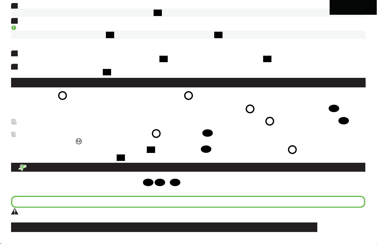
3
EXTENDER LOS BRAZOS
Extienda completamente los brazos del conjunto del brazo/placa mural 15 para dejar suficiente holgura y así evitar tirar de los cables al mover el televisor.
4
COLOCAR LOS CABLES
Español
IMPORTANTE: Curve el manguito del cable en forma de espiral tal y como se muestra para que los cables se enrosquen cuando el televisor se retracte.
Inserte el extremo libre del manguito del cable 19 en los canales del conjunto del brazo/placa mural 15.
3.3 Instale las tiras de recubrimiento
1
INSTALAR LA PARTE INFERIOR
Asegure los cables en el canal inferior del conjunto del brazo/placa mural
2
INSTALAR LA PARTE SUPERIOR
Instale la cubierta de la placa mural superior
16
.
Ajustes
15
colocando la cubierta de la placa mural inferior 16 hasta que emita un chasquido.
PÁGINA 24
NIVEL
Afloje el tornillo regulador L. Nivele su televisor y, a continuación, apriete el tornillo regulador L.
INCLINACIÓN
El televisor debe acomodarse fácilmente al moverlo y, posteriormente, quedar en su lugar. Ajuste la perilla de tensión de inclinación T usando la herramienta para tal propósito 23
si su televisor se inclina naturalmente hacia arriba o hacia abajo.
NOTA: Si no tiene la intención de ajustar la inclinación para los diferentes puntos de visualización, puede ajustar la perilla de tensión de inclinación T con la herramienta para tal propósito 23
y así evitar movimientos no deseados.
NOTA: En caso necesario, puede apretar la perilla de tensión de inclinación T con la llave hexagonal
RETIRAR EL TELEVISOR
1: Desconecte todos los cables del televisor. 2: Retire el soporte para cables 20 y el tornillo de seguridad 21. 3: Tire hacia abajo del anillo de liberación R para liberar el televisor. 4: Levante
con cuidado el televisor del conjunto del brazo/placa mural
Solución de problemas
¡ELEMENTO PESADO! Es posible que necesite ayuda en este paso.
15
.
22
PÁGINA 27
a: Use el separador proporcionado para televisores con partes traseras planas (o bien si quiere que su televisor esté más cerca de la pared).
b: Use el separador proporcionado con el televisor y el separador
para los cables.
11
12 o
13
para televisores con la parte trasera redondeada (irregular) o si necesita espacio adicional
Si tiene dudas sobre la selección de las piezas, contacte con el servicio de atención al cliente en el 1-800-359-5520
PRECAUCIÓN: Evite posibles lesiones personales y daños materiales.
sostendrá el televisor. Si es demasiado largo, el televisor se dañará.
Use la longitud correcta de tornillos para un enrosque adecuado. Si el tornillo es demasiado corto, no
Dimensiones
.
PÁGINA 34
33
Page 34
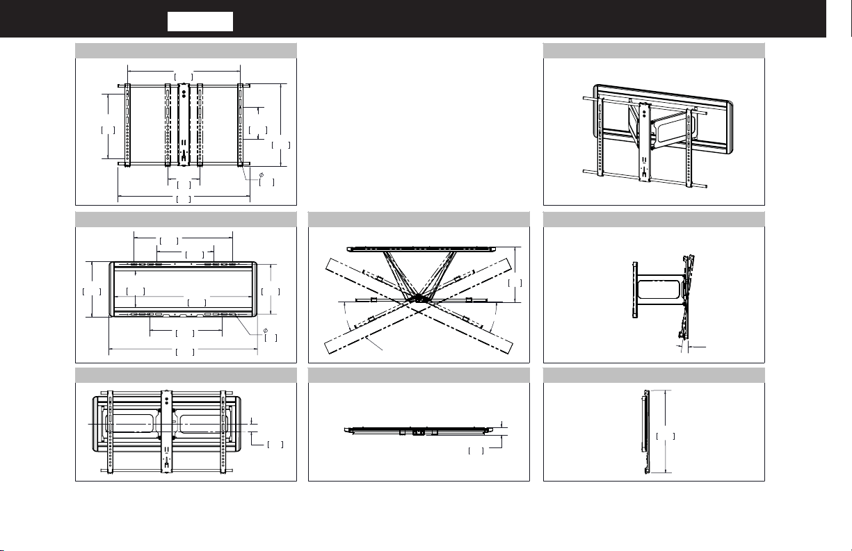
Dimensions
in. [mm]
TV INTERFACE
MAX
15.75
400
MAX
27.56
700.0
MIN
7.87
200.0
MIN
7.9
200
32.2
817
WALL PLATE
24.00
609.6
14.00
355.6
OPENING
13.59
345.2
8.98
228.2
OPENING
17.72
450.0
36.24
920.6
33.54
852.0
FULLY ASSEMBLED MOUNT
11.0
0.43
12.19
309.5
0.34
8.6
OFFSET
3-D
20.10
510.6
TOP VIEW - EXTENDED
25°
SIMULATED 50"
FLAT SCREEN TV
25°
TOP VIEW - RETRACTED
1.88
47.7
1.86
47.3
SIDE VIEW - TILT RANGE
13.5
342
SIDE VIEW - RETRACTED
8°
20.16
512.0
Milestone AV Technologies and its a liated corporations and subsidiaries (collectively, “Milestone”), intend to make this manual accurate and complete. However, Milestone makes no claim that the
information contained herein covers all details, conditions, or variations. Nor does it provide for every possible contingency in connection with the installation or use of this product. The information
contained in this document is subject to change without notice or obligation of any kind. Milestone makes no representation of warranty, expressed or implied, regarding the information contained herein.
Milestone assumes no responsibility for accuracy, completeness or su ciency of the information contained in this document.
34
Page 35
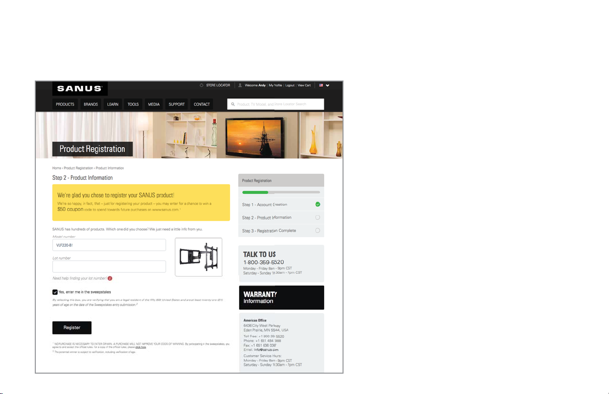
ONE MORE THING: BE A WINNER!
Register your new mount and tell us
how you like it for a chance to win in
our monthly sweepstakes.
Entering is quick and easy. Visit
SANUS.com/1234 and follow three
simple steps for your chance to win.
"Monthly Prize" sweepstakes rules
and restrictions apply. Visit
SANUS.com/1234 for details.
Page 36
IT’S TIME TO SHOW OFF
When you share your handiwork
with your friends, tag
#sanusspaces
for a chance to be featured in the
Inspiration Gallery on SANUS.com.
SANUS.com
WE MAKE IT EASY
All other brand names or marks are used for identification purposes and are trademarks of their respective owners.
SanusSystems
CHAT WITH US
800-359-5520 • [email protected] • SANUS.com
SANUS • 6436 City West Parkway • Eden Prarie, MN 55344 USA
©2016 Milestone AV Technologies. All rights reserved. SANUS is a division of Milestone.
pinterest.com/Sanus
BE INSPIRED
SanusSystems
WATCH AND LEARN
6901-602109 00
 Loading...