

Page 1
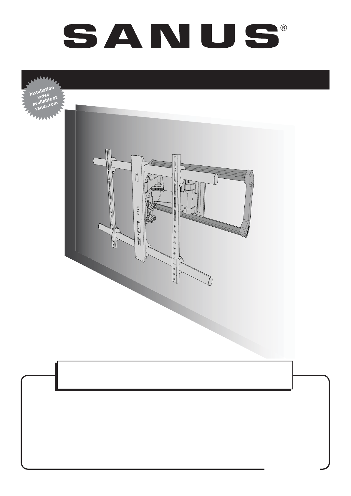
VLF220 Instruction Manual
We are here to help!
Please contact Customer Service with any questions.
Customer Service
Americas: 800-359-5520 • 952-225-6013 • info@sanus.com
UK: 0800 056 2853 • info@sanus.com
Europe, Middle East, and Africa: + 31 40 2324700 • europe.sanus@milestone.com
Asia Paci c: 86 755 8996 9226 • sanus.ap@milestone.com
SANUS • 6436 City West Parkway • Eden Prairie, MN 55344 USA
©2013 Milestone AV Technologies, a Duchossois Group Company. All rights reserved. Sanus is a division of Milestone.
All other brand names or marks are used for identi cation purposes and are trademarks of their respective owners.
sanus.com
Page 2
IMPORTANT SAFETY INSTRUCTIONS – SAVE THESE INSTRUCTIONS – PLEASE READ ENTIRE MANUAL PRIOR TO USE
OR
OPT
OR
OPT
OR
OPT
OR
OPT
OR
OPT
OR
OPT
OR
OPT
OR
OPT
OR
OPT
OR
OPT
OR
OPT
OR
OPT
OR
OPT
OR
OPT
English - How to use this manual
For best results, reference both the text and illustrations. Cut along
the dashed lines to match your language with the illustrations.
Select one item or the other.
This item is optional
English Text Pages 3-11
Français - Utilisation de ce guide
Pour obtenir de meilleurs résultats, reportez-vous à la fois au texte
et aux illustrations. Couper le long de la ligne pointillée pour faire
correspondre les illustrations à votre langue de préférence.
Sélectionnez un article ou l’autre.
Cet article est facultatif.
Texte français page 12-13
Deutsch - Verwendung dieses Handbuchs
Die Montage ist am einfachsten, wenn Sie den Text und die
Abbildungen zusammen verwenden. Schneiden Sie daher den Text
in Ihrer Sprache aus (gestrichelte Linien), um ihn den Abbildungen
gegenüberstellen zu können.
Sie haben die Wahl zwischen einem Element oder einem anderen.
Dieses Element ist optional.
Deutscher Text Seite 14-15
Suomi - Oppaan käyttäminen
Saavutat parhaan tuloksen tutustumalla sekä tekstiin että kuviin.
Leikkaa katkoviivaa pitkin ja yhdistä kuvat ja suomenkielinen teksti.
Valitse toinen vaihtoehdoista.
Tämä vaihtoehto on valinnainen.
Suomenkielinen teksti on sivulla 24-25
Svenska - Så här använder du denna bruksanvisning
För bästa resultat, hänvisa till både text och bilder när du använder
denna bruksanvisning. Klipp längs de streckade linjerna för att
matcha ditt språk med bilderna.
Välj ett objekt eller det andra.
Detta objekt är valfritt.
Svensk text sida 26-27
Русский - Как пользоваться данной инструкцией
Для получения наилучшего результата ориентируйтесь
как на текст, так и на иллюстрации, приведенные в данном
руководстве. Отрежьте по пунктирной линии, чтобы совместить
нужный язык с иллюстрациями.
Выберите один из вариантов.
Эта деталь может не входить в комплект поставки.
Русский текст: стр. 28-29
Español - Cómo usar este manual
Para obtener mejores resultados, consulte el texto y las ilustraciones.
Corte por las líneas discontinuas para hacer coincidir su idioma con
las ilustraciones.
Seleccione uno de los elementos.
Este elemento es opcional.
Texto en español página 16-17
Português -Como usar este manual
Para obter melhores resultados, consulte o texto e as ilustrações.
Recorte nas linhas tracejadas para combinar seu idioma com as
ilustrações.
Selecione um item ou o outro.
Este item é opcional.
Texto em português Página 18-19
Nederlands - Gebruik van deze handleiding
Voor de beste resultaten moet u zowel de tekst als de illustraties
raadplegen. Gebruik de stippellijnen om uw taal bij de illustraties
te plaatsen.
Selecteer een van beide items.
Dit item is optioneel.
Nederlandse tekst op pagina 20-21
Italiano - Uso del manuale
Per risultati ottimali, fare riferimento sia al testo che alle illustrazioni
di questo manuale. Tagliare lungo le linee tratteggiate per abbinare
il testo nella propria lingua alle illustrazioni.
Selezionare uno o l’altro elemento.
Questo elemento è opzionale.
Testo in italiano alle pagine 22-23
Polski - Jak używać tej instrukcji
W celu uzyskania najlepszych rezultatów, korzystając z tej instrukcji,
należy zwrócić uwagę zarówno na tekst, jak i na ilustracje. Przeciąć
wzdłuż przerywanych linii w celu dopasowania języka do ilustracji.
Wybrać jedną pozycję lub drugą.
Ta pozycja jest opcjonalna.
Tekst w języku polskim na stronach 30-31
Česky - Jak používat tuto příručku
Nejlepších výsledků dosáhnete, budete-li při používání této příručky
srovnávat text s ilustracemi. Odstřihněte podél čárkované čáry, aby
bylo možno české instrukce přiřadit k ilustracím.
Vyberte si jednu nebo druhou položku.
Tato položka je volitelná.
Český text se nachází na straně 32-33
日本語 - このマニュアルの使い方
組み立てをうまく行うためには、説明文とイラストの両方を参照してくだ
さい。点線に沿って切り取ると、ご使用の言語とイラストが一致します。
どちらか片方の品目を選択してください。
この品目は、オプションです。
日本語は
中文 - 如何使用本说明书
请同时参阅文字说明和插图以获得最佳阅读效果。请沿着虚线裁剪,
将您的语言与插图匹配起来。
34 -35
ページ
选择一项或另一项。
此项可选。
中文文字说明请参见第 36 -37页
2
6901-002111 05
Page 3
English
5.36
136.1
31.71
805.5
1.41
35.8
17.72
450.0
5
LEVEL
29.56
750.8
75
3.46
87.8
21.21
538.6
-15
TILT
+5
Speci ca
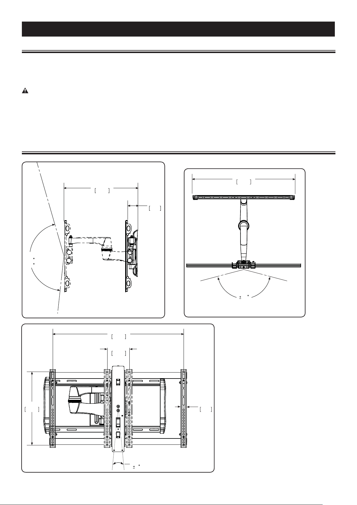
Ù Weight capacity-DO NOT EXCEED: 59 kg (130 lb) includes TV and any accessories
Ù Swivel: ±75°
Ù Tilt: +5° to –15°
Ù Level: ±5°
tions
CAUTION: Avoid potential personal injuries and property damage!
Ù Do not use this product for any purpose not explicitly speci ed by manufacturer.
Ù The wall must be capable of supporting ve times the weight of the TV and mount combined.
Ù This product is not designed for use in metal stud walls!
Ù If you do not understand these instructions, or have doubts about the safety of the installation, assembly or use of this product, contact
Customer Service or call a quali ed contractor.
Ù Manufacturer is not responsible for damage or injury caused by incorrect assembly or use.
Technical Speci cations
6901-002111 05
3
Page 4
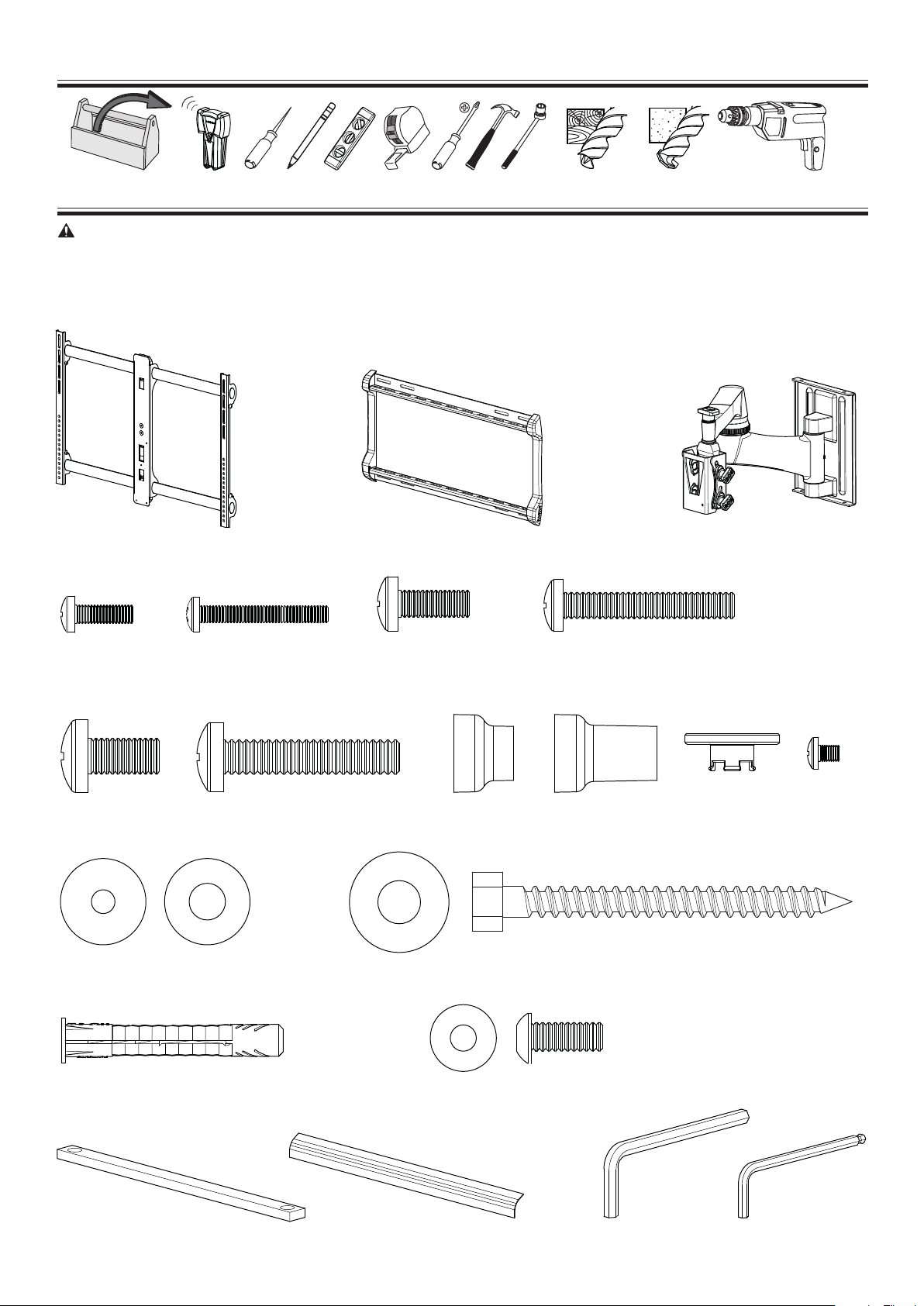
Required Tools
13 mm
(1/2 in.)
5.5mm
(7/32 in.)
10 mm
(3/8 in.)
Supplied Parts and Hardware
WARNING: This product contains small items that could be a choking hazard if swallowed.
Before starting assembly, verify all parts are included and undamaged. If any parts are missing or damaged, do not return the damaged
em to your dealer; contact Customer Service. Never use damaged parts!
it
NOTE: M4, M6, or M8 describes the diameter, mm describes the length of screws that are labeled M0 X 00mm. Not all hardware included
will be used.
[01] x 1
[02] x 1 [03] x 1
M4 x 12mm
[04] x 4
M8 x 16mm
M4 M6 / M8
[14] x 4
[15] x 4
[18] x 4
M4 x 30mm
[05] x 4
M8 x 40mm
[09] x 4[08] x 4
M6 x 14mm
[06] x 4
[16] x 4
[10] x 4
[19] x 4
14mm
M6 x 40mm
[07] x 4
[11] x 4
5/16 x 3½ in.
[17] x 4
1/4-20 x 5/8 in.
[20] x 4
24mm
[12] x 4
10-32 x 1/4 in.
[13] x 1
3/16 in.
[21] x 2
[22] x 2
[23] x 1
4
5/32 in.
[24] x 1
6901-002111 05
Page 5
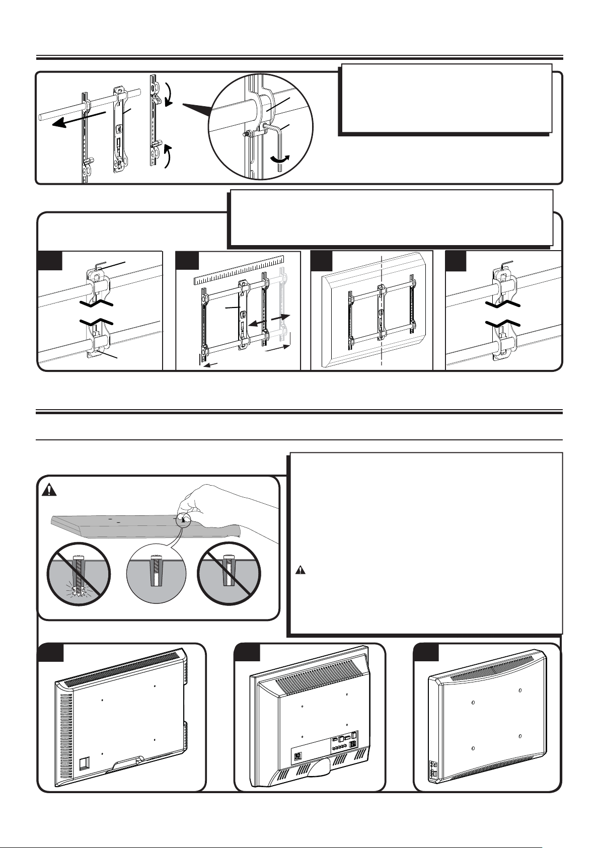
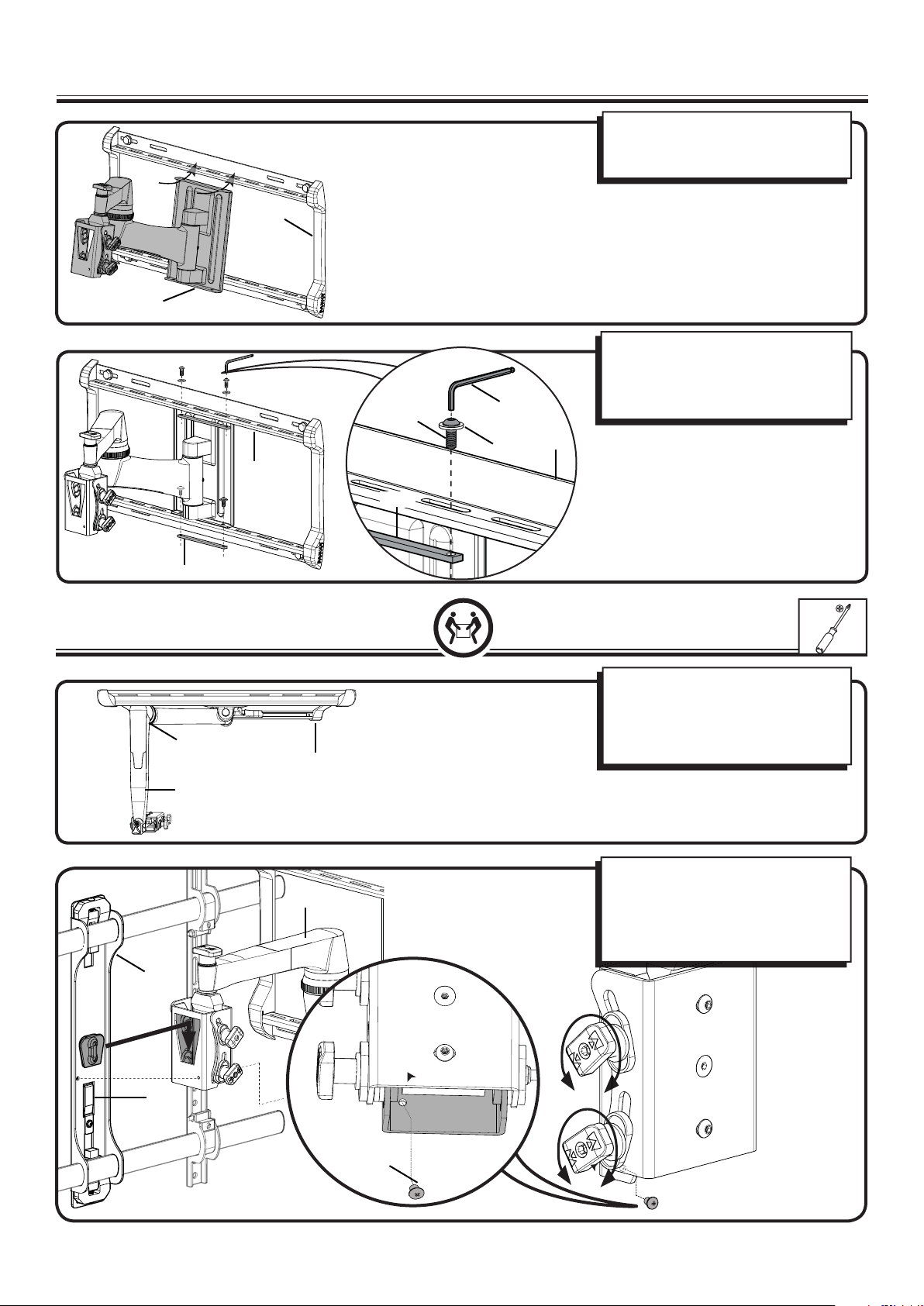
Before You Begin - Determine Your TV Hole Pattern
For all hole patterns other than 400 x 400mm,
proceed to parts A, B, C, and D below. For TVs with
(C)
[01]
[23]
A. Loosen the upper [U] and lower [L] fasteners.
B. Adjust the TV plate [01] to t the hole pattern of your TV.
C. Be sure that the center column is aligned with the center of your TV.
D. Tighten the upper [U] and lower [L] fasteners. Do not overtighten.
400 x 400mm spacing, rst remove the support
tubes and release the locking carriages (C). Then
continue to parts A, B, C, and D below.
[L]
[U]
B
C
[01]
14 - 81 cm
(5-32 in.)
A
1 Select TV Hardware and Mount TV Brackets
1-1 Select the hardware diameter and length
Your TV type will help you determine which hardware con guration to
use. Match your type of TV to the suggested hardware con guration
on the next page.
A. Installation option without spacers (TVs with at backs)
B. Installation option using 14mm spacers (TVs with irregular backs)
C. Installation option using 24mm spacers (For TVs with irregular
backs that require more length than the 14mm spacer provides.)
Hand thread screws into the threaded inserts on the back of your TV
to determine the correct screw diameter (M4, M6, or M8).
CAUTION: Avoid potential personal injuries and property
damage! Verify that there are adequate threads to secure the brackets
to the monitor. If you encounter resistance, stop immediately
and contact customer service. Use the shortest screw and spacer
combination to accommodate your needs. Using hardware that is too
long may damage your TV.
D
A
6901-002111 05
B C
5
Page 6
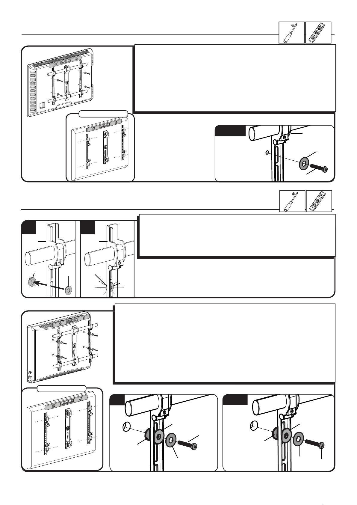
1-2 Attach brackets to a TV with a at back
In step 1, if you selected the:
M4 x 12mm screw [04] use the M4 washer [14].
M6 x14mm screw [06] use the M6/M8 washer [15].
M8 x16mm diameter screw [08] use the M6/M8 washer [15].
Con rm that the brackets are level on the back of the TV.
For 400 x 400mm hole spacing: Resecure the locking carriages (c) and insert the
support tubes.
If you require additional space for cables, recesses, or protrusions, choose one of the
con gurations below.
400 x 400mm
1-2 Attach brackets to a TV with an irregular back
1. Push the shoulder washer [12] through the appropriate openings of the brackets
1
[01]
[10, 11]
[12]
2
[01]
[10, 11]
[12]
[01].
2. Snap shoulder washer [12] into the spacer you selected in step 1-2.
If your TV has a curved or obstructed back, or if you need more room to accommodate
cables, recesses, or protrusions, use either the 14mm, or 24mm spacer [10 or 11].
M4/M6/M8
[01]
[14, 15]
[04, 06, 08]
In step 1, if you selected the:
M4 x 30mm screw [05] use the M4 washer [14] and spacer [10].
M6 x 40mm screw [07], use the M6/M8 washer [15] and spacer [11].
M8 x 40mm screw [09], use the M6/M8 washer [15] and spacer [11].
Con rm that the brackets are level on the back of the TV.
For 400 x 400mm hole spacing: Resecure the locking carriages (c) and insert the support
tubes.
Standard con gurations are shown. For special applications, or if you are uncertain about your
hardware selection, contact Customer Service.
400 x 400mm
M4
[12]
[05]
[10]
[14]
6
M6/M8
[11]
[12]
[15]
[07, 09]
6901-002111 05
Page 7
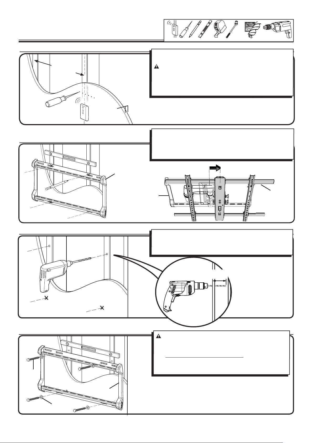
2 Mount the Wall Plate
Wood stud mounting
13 mm
(1/2 in.)
5.5mm
(7/32 in.)
2-1 Locate studs
41 - 61 cm
(16 - 24 in.)
2-2 Mark the wall
≤ 16 mm
(5/8 in.)
[02]
Locate studs. Verify the center of the stud(s) using an awl. a thin nail,
or an edge to edge stud nder.
CAUTION: Avoid potential personal injuries and property
damage!
Ù Drywall covering the wall must not exceed 16 mm (5/8 in.).
Ù Minimum wood stud size: common 51 x 102 mm (2 x 4 in.)
(nominal 38 x 89 mm (1.5 x 3.5 in.))
For assistance in determining wall plate location, see Height Finder at
sanus.com.
Level the wall plate [02] and mark the hole locations. NOTE: TV
will shift 82.5 mm (3.5 in.) to the right when in the home position.
Consider this when selecting the location of your wall mount.
82.5 mm
3.25 in.
[01]
[02]
2-3 Drill pilot holes
2-4 Tighten lag bolts
[17]
Drill pilot holes as illustrated.
Pilot holes MUST be drilled to a depth of 89 mm (3.5 in.), using a 5.5
mm (7/32 in.) diameter drill bit.
89 mm
(3.5 in.)
CAUTION:
Improper use could reduce the holding power of the lag bolt. To
avoid potential injuries or property damage:
Ù DO NOT over-tighten the lag bolts [17].
Ù Tighten the lag bolts only until the washers [16] are pulled
rmly against the wall plate [02].
Avoid potential injuries or property damage!
[16]
6901-002111 05
[02]
7
Page 8
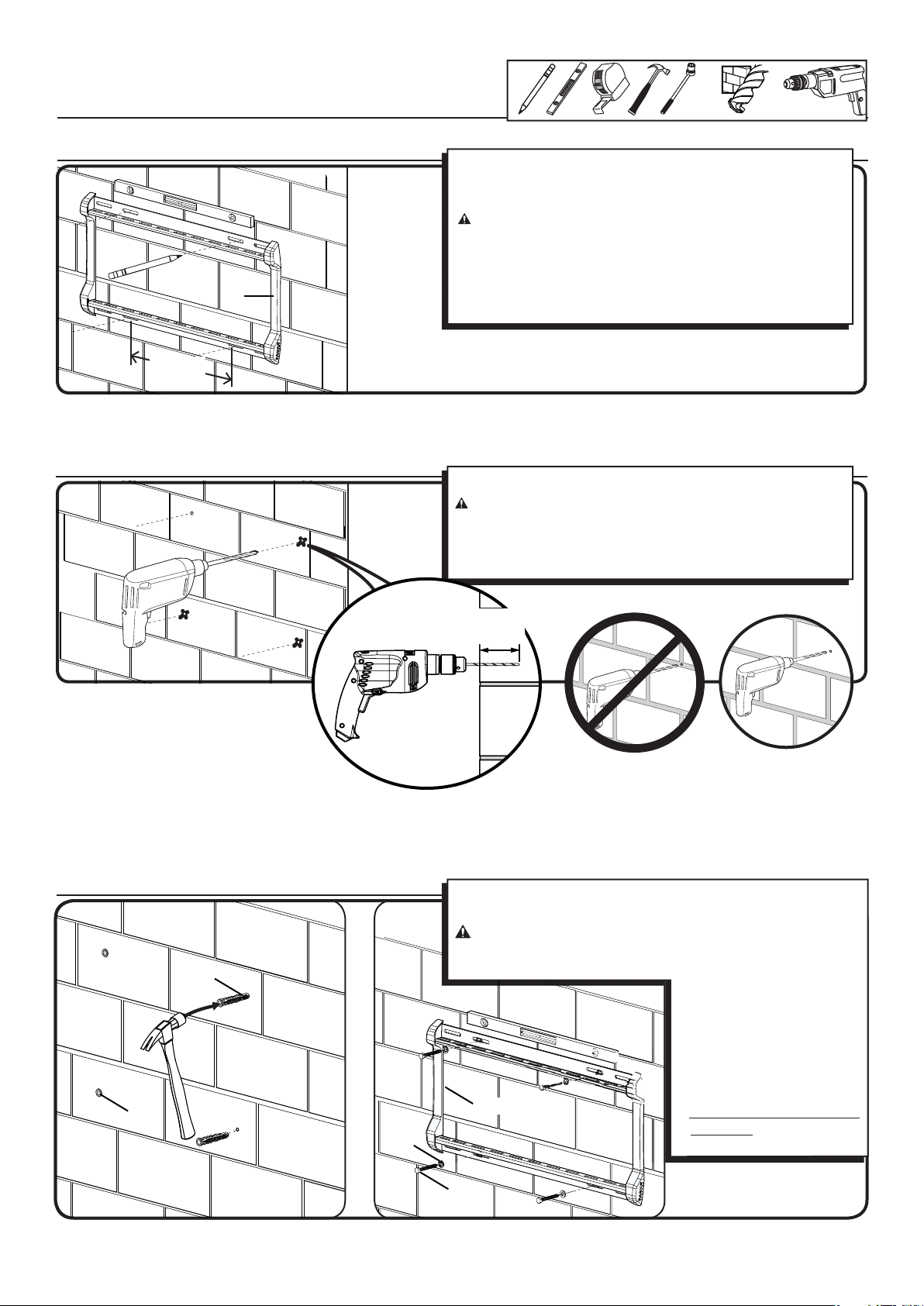
2 Mount the Wall Plate
Solid concrete or concrete block
13 mm
(1/2 in.)
10 mm
(3/8 in.)
2-1 Mark the wall
[02]
406 mm
(16 in.)
2-2 Drill pilot holes
For assistance in determining wall plate location, see Height Finder
at sanus.com.
Level the wall plate [02] and mark the hole locations.
CAUTION:
Ù Mount the wall plate [02] directly onto the concrete surface.
Ù Minimum solid concrete thickness: 203 mm (8 in.)
Ù Minimum concrete block size: 203mm x 203 mm x 406 mm (8
x 8 x 16 in.)
Ù Minimum distance between fasteners: 406 mm (16 in.)
Drill pilot holes as illustrated.
CAUTION:
Ù Pilot holes MUST be drilled to a depth of 89 mm (3.5 in.) using
a 10 mm (3/8 in.) diameter drill bit.
Ù Never drill into the mortar between blocks.
Avoid potential injuries or property damage!
Avoid potential injuries or property damage!
2-3 Insert anchors and lag bolts
[18]
[18]
[16]
89 mm
(3.5 in.)
Insert lag bolt anchors [18]. Then insert lag bolts [17] through the
wall plate [02] and into the anchors.
CAUTION:
Improper use could reduce the holding power of the lag bolt. To avoid
potential injuries or property damage:
[02]
Avoid potential injuries or property damage!
ÙBe sure the anchors [18]
seat ush with the concrete
surface.
ÙTighten the lag bolts [17]
only until the washers [16]
are pulled rmly against the
wall plate [02].
ÙDO NOT over-tighten the lag
bolts [17].
[17]
8
6901-002111 05
Page 9
3 Attach Arm to Wall Plate
[02]
[03]
[02]
[20]
[21]
[23]
[19]
Align the holes at the top and bottom
of the arm [03] to the slots in the wall
plate [02].
Attach plates [21] and the arm [03] to
the wall plate [02] using washer [19]
and screw [20]. Secure with the allen
key [23].
[02]
[21]
4 Attach TV to Arm
(T)
[03]
[01]
[02]
[03]
Position arm [03] so the elbow is
pressed against the wall. Tighten the
tension adjustment (T) to prevent the
arms from moving while installing the
TV bracket.
Attach the TV bracket [01] to the arm
assembly [03]. There is an audible click
when the parts are correctly assembled.
TILT TV UPWARD. Install and tighten
locking screw [13].
(L)
6901-002111 05
[13]
9
Page 10
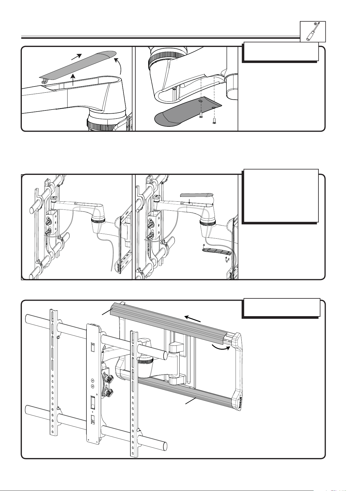
5 Manage Cables
Carefully remove the arm
covers.
Pull each arm to its full
extension then route the
cables through the arm. Leave
enough slack to prevent
stretching the cables when the
arm is moved.
Reattach arm covers.
10
Install the upper and lower
covers [22].
[22]
[22]
6901-002111 05
Page 11
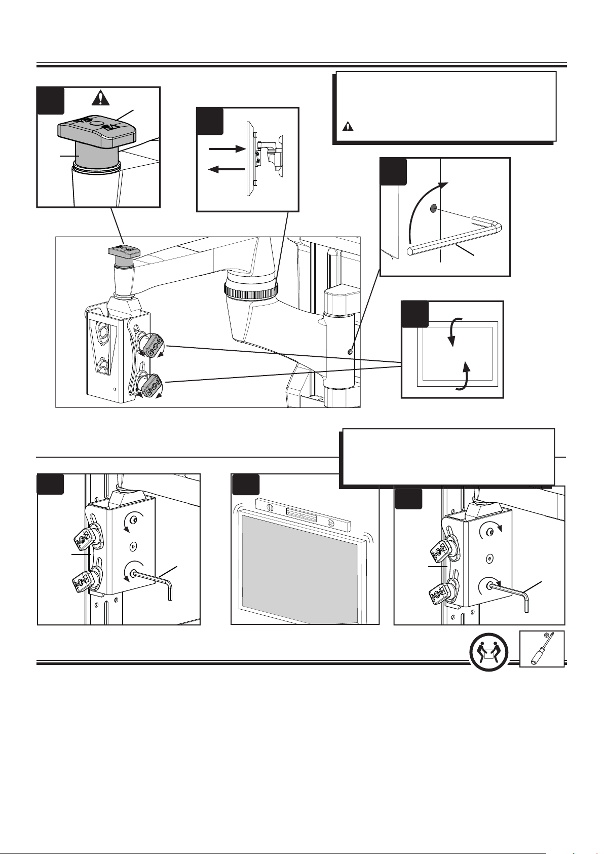
6 Adjustments
A
[03]
(K)
B
A. Adjust left / right swivel tension.
B. Adjust arm extend / retract tension.
C. Adjust up / down tilt tension.
CAUTION: Never remove the tension knob (K).
B
[24]
C
Adjust level.
6-1
A
B
A. Loosen screws
B. Adjust level
C. Re-tighten screws
C
[03]
[23]
Troubleshooting and Maintenance
To remove the TV: (See illustrations in step 4.)
1. Unscrew the locking screw [13].
2. Push and hold the locking tab (L).
3. Carefully lift the TV from the arm [03], then release the locking tab (L).
TV will not hold the downward tilt position and oats upward:
1. Adjust tilt tension setting (see step 6).
2. If the problem persists, use a bracket installation option that uses longer spacers (see step 1-2).
TV will not hold the home position and oats downward:
1. Adjust tilt tension setting (see step 6).
2. If the problem persists, use a bracket installation option that uses shorter spacers (see step 1-2).
[03]
[23]
6901-002111 05
11
Page 12
Français
CONSIGNES DE SÉCURITÉ IMPORTANTES – CONSERVEZ CES INSTRUCTIONS – VEUILLEZ LIRE ATTENTIVEMENT LE MANUEL
AVANT D’UTILISER CE PRODUIT
Caractéristiques techniques
Ù Capacité de charge – NE PAS DÉPASSER: 59kg (130lb) incluant le téléviseur et tous les accessoires.
Ù Pivotement: ±75°
Ù Inclinaison: de +5° à –15°
Ù Niveau: ±5°
Voir à la page 3
ATTENTION: Évitez les dommages matériels et les blessures!
Ù Ne pas utiliser ce produit à d’autres ns que celles spéci ées par le fabricant.
Ù Le mur doit pouvoir supporter cinq fois le poids total du téléviseur et du support.
Ù Ce produit n’est pas conçu pour être utilisé sur des murs dont les montants sont en métal!
Ù Si vous ne comprenez pas toutes ces instructions ou si vous avez des doutes sur la sécurité de l’installation, du montage ou de l’utilisation de ce produit,
veuillez contacter un installateur quali é ou le service à la clientèle.
Ù Le fabricant n’est pas responsable des blessures ou des dommages causés par une mauvaise utilisation ou un montage incorrect.
Caractéristiques techniques
Pièces et quincaillerie fournies
- Voir à la page 3
- Voir à la page 4
AVERTISSEMENT: Ce produit contient de petites pièces qui peuvent représenter un risque d’étou ement.
Avant de commencer l’assemblage, assurez-vous que toutes les pièces sont présentes et qu’elles ne sont pas endommagées. Si une pièce est manquante ou
endommagée, ne retournez pas les pièces endommagées à votre revendeur. Contactez plutôt le service clientèle. N’utilisez jamais de pièces endommagées!
REMARQUE: M4, M6, ou M8 décrit le diamètre et mm décrit la longueur des vis qui sont identi ées M0 X 00mm. Les pièces comprises ne doivent pas
nécessairement être toutes utilisées.
Avant de commencer - Déterminez la con guration des trous du téléviseur.
Pour les con gurations de trous di érentes de 400x400mm, passez aux parties A, B, C, et D ci-dessous. Pour les téléviseurs avec un espacement de
400x400mm, retirez en premier les barres de support et les xations verrouillables (c). Ensuite poursuivre avec les parties A, B, C, et D ci-dessous.
A. Desserrez les attaches du haut [U] et du bas [L].
B. Réglez la plaque du téléviseur [01] pour qu’elle s’ajuste à la con guration de trous de votre téléviseur.
C. Assurez-vous que la colonne centrale est alignée avec le centre de votre téléviseur.
D. Resserrez les attaches du haut [A] et du bas [B]. Ne pas trop serrer.
Voir à la page 5
1 Sélectionnez la quincaillerie et le support de xation pour le téléviseur
1-1 Sélectionnez lediamètre et la longueur de la quincaillerie
Le type de téléviseur vous aidera à choisir la con guration de la quincaillerie à utiliser. Faites correspondre votre type de téléviseur à l’une des con gurations de
quincaillerie suggérées à la page suivante.
A. Option d’installation sans entretoises (téléviseur à dos plat)
B. Option d’installation avec des entretoises de de 14mm (téléviseur avec dos irrégulier)
C. Option d’installation avec des entretoises de 24mm (pour les téléviseurs avec un dos irrégulier qui nécessitent plus long que les 14mm donnés par les entretoises.)
Serrez à la main les vis dans les ori ces letées au dos du téléviseur a n de déterminer le diamètre de vis approprié (M4, M6, ou M8).
ATTENTION: Évitez les dommages matériels et les blessures! Assurez-vous qu’il y a su samment de lets pour installer solidement les supports sur le
moniteur. Si vous sentez une résistance, arrêtez immédiatement et contactez le Service à la clientèle. Utilisez la combinaison la plus courte possible de vis et
d’entretoise nécessaire. L’utilisation d’une quincaillerie trop longue pourrait endommager le téléviseur.
Voir à la page 5
1-2 Attachez les brides de montage au téléviseur dont l’arrière est plat
À l’étape 1, si vous avez choisi:
la vis M4 x 12mm [04] utilisez la rondelle M4 [14].
la vis M6 x 14mm [06] utilisez la rondelle M6/M8 [15].
la vis M8 x 16mm [08] utilisez la rondelle M6/M8 [15].
Assurez-vous que les supports sont l’horizontale (à niveau) derrière le téléviseur.
Pour les téléviseurs avec un espacement de 400x400mm: Resserrez les xations verrouillables (c) et insérez les barres de support.
Si vous avez besoin de plus d’espace à cause des câbles, des creux ou des protubérances, sélectionnez l’une des con gurations ci-dessous.
1-2 Attachez les brides de montage au téléviseur avec dos irrégulier
1. Poussez la rondelle à épaulement [12] dans les ori ces appropriés des supports [01].
2. Pressez la rondelle à épaulement [12] dans l’entretoise que vous avez sélectionné à l’étape 1-2.
Si le dos de votre téléviseur est incurvé ou obstrué, ou si vous avez besoin d’un espace plus grand pour les câbles, les creux ou les protubérances, utilisez les
entretoises de 14mm ou 24mm [10 ou 11].
À l’étape 1, si vous avez choisi:
la vis M4 x 30mm [05] utilisez la rondelle M4 [14] et l’entretoise [10].
la vis M6 x 40mm [07] utilisez la rondelle M6/M8 [15] et l’entretoise [11].
la vis M8 x 40mm [09] utilisez la rondelle M6/M8 [15] et l’entretoise [11].
Assurez-vous que les supports sont l’horizontale (à niveau) derrière le téléviseur.
Pour les téléviseurs avec un espacement de 400x400mm: Resserrez les xations verrouillables (c) et insérez les barres de support.
Les con gurations standard sont illustrées. Consultez le Service à la clientèle pour toute application particulière ou si vous avez des doutes quant à la
quincaillerie à utiliser.
Voir à la page 5
Voir à la page 6
Voir à la page 6
12
6901-002111 05
Page 13

2 Installation sur des murs à montant de bois
Voir à la page 7
2-1 Trouvez les montants
Pour obtenir de l’aide a n de déterminer l’emplacement de la plaque murale, consultez le site sanus.com sous la rubrique «Height Finder».
Trouvez les montants. Véri ez le centre du montant à l’aide d’un poinçon ou d’un clou n, ou utilisez un localisateur bord à bord.
ATTENTION: Évitez les dommages matériels et les blessures!
Ù L’épaisseur du matériau de revêtement de mur ne doit pas excéder 16mm (5/8po).
Ù Dimension minimale du montant de bois: commune 51x102mm (2x4po) (nominale 38x89mm/1,5x3,5po).
2-2 Marquez l’emplacement sur le mur
Mettez la plaque murale [02] à niveau et marquez les emplacements des trous. REMARQUE: Le téléviseur pivotera de 9cm (3,5po) vers la droite en position
«Repos». Veuillez considérer cet aspect lorsque vous choisirez l’emplacement de votre support mural.
2-3 Percez des trous de guidage
Percez des avant-trous tel qu’illustré.
Les avant-trous DOIVENT être percés à une profondeur de 89mm (3,5 po) à l’aide d’un foret de 5,5mm (7/32po).
2-4 Serrez les boulons tire-fond Serrez les boulons tire-fonds.
ATTENTION:
dommage matériel ou blessures!
Ù NE PAS trop serrer les boulons tire-fond [17].
Ù Serrez les boulons tire-fond [16] jusqu’à ce que les rondelles s’appuient fermement sur la plaque murale [02].
2 Montage mural
Évitez tout dommage matériel ou blessure! Une utilisation inadéquate peut réduire la force de rétention du boulon tire-fond. Évitez tout
Voir à la page
2-1 Marquez l’emplacement sur le mur
Pour obtenir de l’aide a n de déterminer l’emplacement de la plaque murale, consultez le site sanus.com sous la rubrique «Height Finder».
Mettez la plaque murale [02] à niveau et marquez les emplacements des trous.
ATTENTION:
Ù Montez la plaque murale [02] directement sur la surface de béton.
Ù Épaisseur minimale du béton coulé: 203mm (8po)
Ù Dimension minimale du bloc de béton: 203x203x406mm (8x8x16po)
Évitez tout dommage matériel ou blessure!
2-2 Percez des trous de guidage
ATTENTION:
Ù Les avant-trous DOIVENT être percés à une profondeur de 89mm (3.5po) à l’aide d’un foret de 10mm (3/8po) de diamètre.
Ù Ne jamais percer dans le mortier entre les blocs.
Évitez tout dommage matériel ou blessure!
2-3 Insérez les douilles à expansion et les boulons tire-fond
Insérez les douilles à expansion des boulons tire-fond [18]. Insérez ensuite les boulons tire-fond [17] dans la plaque murale [02] et dans les douilles.
ATTENTION:
dommage matériel ou blessures !
Ù Assurez-vous que les douilles à expansion [18] ne dépassent pas de la surface de béton.
Ù Serrez les boulons tire-fond [17] jusqu’à ce les rondelles [16] s’appuient fermement sur la plaque murale [02].
Ù NE PAS trop serrer les boulon tir
Évitez tout dommage matériel ou blessure! Une utilisation inadéquate peut réduire la force de rétention du boulon tire-fond. Évitez tout
3 Attachez le bras à la plaque murale
Voir à la page 7
Voir à la page 7
Voir à la page 7
Béton coulé ou blocs de béton
Voir à la page 8
Percez des avant-trous tel qu’illustré. Voir à la page 8
e-fond [17].
Voir à la page 9
Voir à la page 8
Voir à la page 8
Alignez les trous en haut et en bas du bras [03] avec les fentes de la plaque murale [02].
Attachez les plaques [21] et le bras [03] à la plaque murale [02] à l’aide de la rondelle [19] et de la vis [20]. Serrer avec la clé Allen [23].
4 Fixez le téléviseur au bras
Placez le bras [03] pour que le joint coudé s’appuie sur le mur. Serrez le dispositif de réglage de tension (T) de façon à immobiliser les bras durant
l’installation de la bride de montage du téléviseur.
Installez la bride de montage du t
PIVOTEZ LE TÉLÉVISEUR VERS LE HAUT.Installez et serrez la vis de verrouillage [13].
5 Gestion des câbles
Enlevez les caches des bras.
Allongez complètement les bras et faites passer les câbles dans les bras. Laissez su samment de jeu pour éviter que les câbles soient étirés lorsque les bras
sont déplacés.
Re xez les caches du bras. Installer les couvercles supérieur et inférieur [22].
6 Réglages
1. Réglez la tension de pivotement à gauche/droite.
ATTENTION: Ne jamais retirer l’écrou de tension (K).
2. Réglez la tension d’extension/rétraction des bras.
3. Réglez la tension d’inclinaison vers le haut/bas.
Voir à la page 11
Voir à la page 10
Dépannage et maintenance
Pour retirer le téléviseur : (Consultez les illustrations à l'étape 4.)
1. Desserrez la vis de verrouillage [13].
2. Poussez a n de libérer la languette de verrouillage (L).
3. Levez le téléviseur en faisant à partir de l’arbre [03].
Le téléviseur ne tiendra pas sa position de pivotement vers le bas et otte vers le haut:
1. Ajustez le réglage de la tension de pivotement (se reporter à l'étape 6).
2. Si le problème persiste, utilisez une option d’installation de support qui n’utilise pas d’entretoise (se reporter à l'étape 1-2).
Le téléviseur ne tiendra pas sa position d'origine et otte vers le bas :
1. Ajustez le réglage de la tension de pivotement (se reporter à l'étape 6).
2. Si le problème persiste, utilisez une option d’installation de support qui utilise des entretoises plus courtes (se reporter à l'étape 1-2).
Voir à la page 9
éléviseur [01] sur l’assemblage du bras [03]. Vous devriez entendre un clic lorsque les pièces sont correctement assemblées.
6-1
Voir à la page 11
Réglage du niveau.
A. Desserrer les vis
B. Réglage du niveau
C. Resserrez les vis
Voir à la page 11
6901-002111 05
13
Page 14

Deutsch
WICHTIGE SICHERHEITSHINWEISE – BEWAHREN SIE DIESE HINWEISE SORGFÄLTIG AUF – LESEN SIE VOR DEM GEBRAUCH DES
PRODUKTS BITTE DAS GESAMTE HANDBUCH
Spezi kationen
Ù Höchstzulässiges Gesamtgewicht-NICHT ÜBERSCHREITEN: 59 kg (130 lb) inkl. Fernseher und Zubehör
Ù Schwenkbar: ±75°
Ù Neigungswinkel: +5° bis -15°
Ù Höhe: ±5°
Siehe Seite 3
ACHTUNG: Vermeiden Sie Verletzungen und Sachschäden!
Ù Verwenden Sie dieses Produkt nur für den vom Hersteller ausdrücklich angegebenen Zweck.
Ù Die Wand muss das Fün ache des Gesamtgewichts von Fernseher und Halterung tragen können.
Ù Dieses Produkt ist nicht für die Verwendung an Wänden mit Metallträgern geeignet!
Ù Falls Sie diese Anleitung nicht verstehen sollten oder Zweifel bezüglich der sicheren Montage, des Zusammenbaus oder der Verwendung des Produkts
haben, kontaktieren Sie den Kundendienst oder einen quali zierten Auftragnehmer.
Ù Der Hersteller haftet nicht für Schäden oder Verletzungen, die durch falsche Montage oder Verwendung verursacht werden.
Technische Daten
Mitgelieferte Teile und Befestigungsmaterialien
- Siehe Seite 3
- Siehe Seite 4
WARNUNG: Dieses Produkt enthält kleine Teile, die beim Verschlucken zum Erstickungstod führen können.
Prüfen Sie vor Montagebeginn, ob alle Teile vorhanden und unbeschädigt sind. Falls Teile fehlen oder beschädigt sind, bringen Sie das Produkt nicht zum
Händler zurück, sondern wenden Sie sich an den Kundendienst. Verwenden Sie niemals beschädigte Teile!
HINWEIS: Bei Schrauben mit der Bezeichnung M0 X 00mm steht M4, M6 oder M8 für den Durchmesser und mm für die Länge. Es wird nicht das gesamte
mitgelieferte Befestigungsmaterial verwendet.
Vorbereitung - Bestimmen Sie das Lochbild Ihres Fernsehers
Bei allen Lochbildern außer 400 x 400 mm gehen Sie bitte direkt zu den nachfolgenden Schritten A, B, C und D weiter. Entfernen Sie bei Fernsehern mit dem
Lochbild 400 x 400 mm zuerstdie Stützrohre und lösen Sie die Sperrmechanismen (c). Fahren Sie dann ebenfalls mit den nachstehenden Schritten A, B, C und D fort.
A. Lösen Sie die obere [U] und die untere [L] Schraube.
B. Passen Sie die Platte [01] an das Lochbild Ihres Fernsehers an.
C. Die mittlere Säule muss genau mit der Mitte des Fernsehers ausgerichtet sein.
D. Ziehen Sie die obere [A] und die untere [B] Schraube wieder an. Ziehen Sie die Schrauben nicht zu fest an.
1 Auswählen der Befestigungsmaterialien und Montieren der Anschlussplatten für den Fernseher
Siehe Seite 5
Siehe Seite 5
1-1 Wählen Sie Länge und Durchmesser der Befestigungsmaterialien
Ihr Fernsehertyp wird Ihnen beim Bestimmen der richtigen Kon guration der Befestigungsmaterialien behil ich sein. Stimmen Sie Ihren Fernsehertyp mit den
Befestigungsmaterialien nach den auf der nächsten Seite angegebenen Kon gurationsvorschlägen ab.
A. Montage ohne Abstandhalter (Fernseher mit acher Rückseite)
B. M
ontage mit 14-mm-Abstandhaltern (Fernseher mit unebener Rückseite)
C. Montage mit 24-mm-Abstandhaltern (Für Fernseher mit unebener Rückseite, für die 14-mm-Abstandhalter zu kurz sind.)
Bestimmen Sie den geeigneten Schraubendurchmesser (M4, M6 oder M8), indem Sie die Schrauben mit der Hand in die Gewindeeinsätze an der Rückseite
Ihres Fernsehers schrauben.
ACHTUNG: Vermeiden Sie Verletzungen und Sachschäden! Stellen Sie sicher, dass geeignete Gewindegänge für die Befestigung der Anschlussplatten
am Monitor vorhanden sind. Falls Sie auf Widerstand stoßen, brechen Sie die Montage unverzüglich ab und rufen Sie den Kundendienst an. Verwenden
Sie die kürzeste Schrauben-Abstandhalter-Kombination, die unter den gegebenen Montagebedingungen möglich ist. Durch die Verwendung von zu langen
Schrauben kann Ihr Fernseher beschädigt werden.
1-2 Befestigen der Anschlussplatten an einem Fernseher mit acher Rückseite
Verwenden Sie in Schritt 1 mit
M4 x 12 mm-Schrauben [04] die M4-Unterlegscheiben [14].
M6 x 14 mm-Schrauben [06] die M6/M8-Unterlegscheiben [15].
M8 x 16 mm-Schrauben [08] die M6/M8-Unterlegscheiben [15].
Vergewissern Sie sich, dass die Anschlussplatten ach auf der Rückseite des Fernsehers anliegen.
Bei einem Lochbild von 400 x 400 mm: Befestigen Sie die Sperrmechanismen (c) erneut sicher und führen Sie die Stützrohre ein.
Wenn Sie mehr Platz für Kabel, Vertiefungen oder Überstände benötigen, wählen Sie eine der nachstehenden Kon gurationen.
1-2 Befestigen der Anschlussplatten an einem Fernseher mit unebener Rückseite
1. Stecken Sie die Ansatzscheiben [12] durch die entsprechenden Ö nungen der Anschlussplatten [01].
2. Drücken Sie die Ansatzscheibe [12] in den Abstandhalter , den Sie in Schritt 1-2 ausgewählt haben.
Wenn Ihr Fernseher eine gewölbte oder unebene Rückseite aufweist oder Sie mehr Platz für Kabel, Vertiefungen oder Überstände benötigen, verwenden Sie
die 14-mm- oder 24-mm-Abstandhalter [10 bzw. 11].
Verwenden Sie in Schritt 1 mit
M4 x 30 mm-Schrauben [05] die M4-Unterlegscheiben [14] und die Abstandhalter [10].
M6 x 40 mm-Schrauben [07] die M6/M8-Unterlegscheiben [15] und die Abstandhalter [11].
M8 x 40 mm-Schrauben [09] die M6/M8 Unterlegscheiben [15] und die Abstandhalter [11].
Vergewissern Sie sich, dass die Anschlussplatten ach auf der Rückseite des Fernsehers anliegen.
Bei einem Lochbild von 400 x 400 mm: Befestigen Sie die Sperrmechanismen (c) erneut sicher und führen Sie die Stützrohre ein.
Die Abbildungen zeigen Standardkon gurationen. Für Spezialanwendungen oder, wenn Sie sich bei der Wahl der Befestigungsmaterialien nicht sicher sind,
wenden Sie sich an den Kundendienst.
Siehe Seite 5
Siehe Seite 6
Siehe Seite 7
14
6901-002111 05
Page 15

2 Wandmontage Montage an Holzbalken
Siehe Seite 7
2-1 Suchen Sie die Balken
Hilfe zum Bestimmen der geeigneten Wandplattenposition nden Sie unter Height Finder auf sanus.com.
Suchen Sie die Balken. Stechen Sie mit einer Ahle oder einem dünnen Nagel die Mitte des Balkens bzw. der Balken an, oder verwenden Sie einen Kante-zu-
Kante-Balkensucher.
VORSICHT: Vermeiden Sie Verletzungen und Sachschäden!
Ù Jegliches Material, das die Wand bedeckt, darf 16mm (5/8 Zoll) nicht überschreiten.
Ù Mindestmaße der Holzbalken: üblich 51 x 102 mm (2 x 4 Zoll) (nominell 38 x 89 mm /1,5 x 3,5 Zoll).
2-2 Markieren Sie Bohrstellen an der Wand
Richten Sie die Wandplatte [02] aus und markieren Sie die Stellen für die Bohrlöcher. HINWEIS: Der Fernseher lässt sich in der Ausgangsstellung 9 cm (6 Zoll)
nach rechts oder links verschieben. Berücksichtigen Sie dies bei der Auswahl der Montagestelle für die Wandhalterung.
2-3 Bohren Sie Vorbohrungen
Bohren Sie Vorbohrungen wie in der Abbildung dargestellt.
Vorbohrungen MÜSSEN mit einem 5,5 mm-Bohrer (7/32 Zoll) bis zu 89 mm (3,5 Zoll) tief gebohrt werden.
2-4 Anziehen der Ankerschrauben
Ziehen Sie die Ankerschrauben an.
VORSICHT:
Vermeiden Sie Verletzungen und Sachschäden:
Ù Ziehen Sie die Ankerschrauben [17] NICHT zu fest an.
Ù Ziehen Sie die Ankerschrauben nur so weit an, bis die Unterlegscheiben [16] fest an der Wandplatte [02] anliegen.
Vermeiden Sie Verletzungen und Sachschäden! Eine unsachgemäße Verwendung kann die Haltekraft der Ankerschraube verringern.
Siehe Seite 7
Siehe Seite 7
2 Wandmontage Massivbeton oder Betonblöcke
2-1 Markieren Sie Bohrstellen an der Wand
Hilfe zum Bestimmen der geeigneten Wandplattenposition nden Sie unter Height Finder auf sanus.com.
Richten Sie die Wandplatte [02] aus und markieren Sie die Stellen für die Bohrlöcher.
VORSICHT:
Ù Montieren Sie die Wandplatte [02] direkt an der Beton äche.
Ù Mindestdicke der Massivbetonwand: 203 mm (8 Zoll)
Ù Mindestmaße der Betonblöcke: 203 x 203 x 406 mm (8 x 8 x 16 Zoll)
2-2 Bohren Sie Vorbohrungen
Bohren Sie Vorbohrungen wie in der Abbildung dargestellt.
VORSICHT:
Ù Vorbohrungen MÜSSEN mit einem 10-mm-Bohrer (3/8 Zoll) bis zu 89 mm (3,5 Zoll) tief gebohrt werden.
Ù Bohren Sie niemals in den Mörtel zwischen den Blöcken.
Vermeiden Sie Verletzungen und Sachschäden!
Siehe Seite 8
Vermeiden Sie Verletzungen und Sachschäden!
2-3 Einsetzen der Dübel und Ankerschrauben
Setzen Sie die Ankerschraubendübel [18] ein. Führen Sie dann die Ankerschrauben [17] durch die Wandplatte [02] in die Dübel ein.
VORSICHT:
Vermeiden Sie Verletzungen und Sachschäden:
Ù Stellen Sie sicher, dass die Dübel [18] bündig mit der Beton äche abschließen.
Ù Ziehen Sie die Ankerschrauben [17] nur so weit an, bis die Unterlegscheiben [16] fest an der Wandplatte [02] anliegen.
Ù Ziehen Sie die Ankerschrauben [17] NICHT zu the fes an.
Vermeiden Sie Verletzungen und Sachschäden! Eine unsachgemäße Verwendung kann die Haltekraft der Ankerschraube verringern.
3 Befestigen des Arms an der Wandplatte
Siehe Seite 7
Siehe Seite 8
Siehe Seite 8
Siehe Seite 8
Siehe Seite 9
Richten Sie die Löcher oben und unten am Arm [03] mit den Schlitzen in der Wandplatte [02] aus.
Befestigen Sie die Platten [21] und den Arm [03] mithilfe der Schrauben [20] und Unterlegscheiben [19] an der Wandplatte [02]. Ziehen Sie die Schrauben
mit dem Inbusschlüssel [23] fest.
4 Befestigen des Fernsehers am Arm
Positionieren Sie den Arm [03] so, dass ein Winkelstück an der Wand lehnt. Ziehen Sie Einstellschraube (T) an, um zu verhindern, dass sich der Arm während
der Montage der Anschlussplatte des Fernsehers bewegen.
Befestigen Sie die Anschlussplate [01] des F
klickenden Geräusch ein.
NEIGEN SIE DEN FERNSEHER NACH OBEN. Setzen Sie die Feststellschraube [13] ein und ziehen Sie sie fest.
5 Kabelführung
Entfernen Sie die Armabdeckungen.
Ziehen Sie die Arme vollständig aus und verlegen Sie die Kabel durch die Arme. Lassen Sie genug Spiel, um ein Überdehnen der Kabel beim Bewegen des
Arms zu verhindern.
Bringen Sie die Armabdeckungen wieder an. Bringen Sie die obere und untere Abdeckung [22] an.
6 Einstellungen
1. Stellen Sie die Spannung für die Drehung nach rechts/links ein.
ACHTUNG: Entfernen Sie die Spannmuttern (K) nie vollständig.
2. Stellen Sie die Spannung zum Ausziehen/Einfahren des Arms ein.
3. Stellen Sie die Spannung für die Neigung nach oben/unten ein.
6-1
Siehe Seite 11
Einstellen der Höhe.
A. Lösen Sie die Schrauben
B. Stellen Sie die Höhe ein
C. Ziehen Sie die Schrauben wieder an
Siehe Seite 10
Siehe Seite 11
ernsehers an der Armvorrichtung [03]. Wenn die Teile richtig zusammengebaut wurden, rasten sie mit einem
Siehe Seite 9
6901-002111 05
15
Page 16

Español
INSTRUCCIONES IMPORTANTES DE SEGURIDAD. GUARDE ESTAS INSTRUCCIONES. LEA TODO EL MANUAL ANTES DE UTILIZAR
ESTE PRODUCTO.
Especi caciones
Ù Peso máximo-NO SUPERAR: 59 kg (130 lb) incluidos el televisor y los accesorios
Ù Giro: ±75°
Ù Inclinación: +5° a –15°
Ù Nivelación: ±5°
Consulte la página 3
PRECAUCIÓN: Evite posibles lesiones personales y daños materiales.
Ù No utilice este producto para ningún otro propósito que no sea el explícitamente especi cado por el fabricante.
Ù La pared debe ser capaz de soportar hasta cinco veces el peso del televisor y la montura combinados.
Ù ¡Este producto no está diseñado para utilizar en paredes con montantes de metal!
Ù Si no entiende las instrucciones o si tiene dudas acerca de la seguridad de la instalación, el montaje o el uso del producto, póngase en contacto con el
servicio de atención al cliente de Sanus Systems o llame a un técnico cuali cado.
Ù El fabricante no se responsabiliza de ningún daño o lesión resultante del montaje incorrecto o el uso indebido.
Especi caciones técnicas
Piezas y elementos de sujeción suministrados
- Consulte la página 3
- Consulte la página 4
ADVERTENCIA: Este producto contiene piezas pequeñas que podrían causar as xia si se tragasen.
Antes de comenzar a montar la unidad
devuelva el elemento defectuoso al distribuidor. Póngase en contacto con el servicio de atención al cliente. Nunca utilice piezas en mal estado.
NOTA: M4, M6 o M8 describe el diámetro, mm describe la longitud de los tornillos que están etiquetados M0 X 00mm. No se utilizarán todos los elementos
de sujeción incluidos.
Antes de empezar - Determine el patrón de ori cios de su televisor
Para todos los patrones de ori cios distintos de 400 x 400mm, continúe con las partes A, B, C y D siguientes. Para televisores con una separación entre
ori cios de 400 x 400 mm, primeroretire los tubos de soporte y libere los carros de bloqueo (c). Después continúe con las partes A, B, C y D siguientes.
A. A oje las sujeciones superiores [U] e inferiores [L].
B. Ajuste la placa del televisor [01] de modo que encaje en el patrón de ori cios de su televisor.
C. Asegúrese de que la columna central esté alineada con el centro de su televisor.
D. Apriete las sujeciones superior [A] e inferior [B]. No las apriete demasiado.
, veri que que todas las piezas estén incluidas y en buen estado. En caso de que falten piezas o alguna esté dañada, no
Consulte la página 5
1 Seleccione los elementos de sujeción y los soportes de la montura del televisor
1-1 Seleccione el diámetro y la longitud de los elementos de sujeción
El tipo de televisor le ayudará a determinar la con guración de elementos de sujeción que debe utilizar. Compruebe la con guración de elementos de sujeción
recomendada para su tipo de televisor en la página siguiente.
A. Opción de instalación sin espaciadores (televisores con parte posterior plana).
B. Opción de instalación utilizando espaciador
C. Opción de instalación utilizando espaciadores de 24mm (Para televisores con la parte posterior irregular que requieren más longitud de la que ofrece el
espaciador de 14mm.)
Enrosque manualmente los tornillos en los ori cios roscados de la parte posterior del televisor para determinar el diámetro correcto del tornillo (M4, M6 o M8).
PRECAUCIÓN: Evite posibles lesiones personales y daños materiales. Veri que que haya roscas adecuadas para sujetar los soportes al monitor. Si nota
resistencia, no continúe y póngase en contacto con el servicio de atención al cliente. Utilice la combinación de tornillo y espaciador más corta que se ajuste a
sus necesidades. Si usa elementos de sujeción demasiado largos puede dañar el televisor.
es de 14mm (televisores con la parte posterior irregular)
Consulte la página 5
1-2 Colocación de los soportes en un televisor con la parte posterior plana
En el paso 1, si seleccionó el:
tornillo M4 x 12mm [04] utilice la arandela M4 [14].
tornillo M6 x 14mm [06] utilice la arandela M6/M8 [15].
tornillo con diámetro M8 x 16mm [08] utilice la arandela M6/M8 [15].
Asegúrese de que los soportes estén a igual altura en la parte posterior del televisor.
Para una separación entre ori cios de 400 x 400mm: Vuelva a asegurar los carros de bloqueo (c) e inserte los tubos de soporte.
Si necesita espacio adicional para cables, huecos o protuberancias, elija una de las con guraciones siguientes.
1-2 Colocación de los soportes en un televisor con la parte posterior irregular
1. Empuje la arandela de aislamiento [12] a través de las aberturas correspondientes de los soportes [01].
2. Encaje la arandela de aislamiento [12] en el espaciador que seleccionó en el paso 1-2.
Si el televisor tiene la parte posterior curvada u obstruida, o si necesita más espacio para cables, huecos o protuberancias, utilice los espaciadores de 14mm o
24mm [10 o 11].
En el paso 1, si seleccionó el:
tornillo M4 x 30mm [05] utilice la arandela [14] y el espaciador M4 [10].
tornillo M6 x 40mm [07] utilice la arandela [15] y el espaciador M6/M8 [11].
tornillo M8 x 40mm [09] utilice la arandela [15] y el espaciador M6/M8 [11].
Asegúrese de que los soportes estén a igual altura en la parte posterior del televisor.
Para una separación entre ori cios de 400 x 400mm: Vuelva a asegurar los carros de bloqueo (c) e inserte los tubos de soporte.
Se muestran las con guraciones estándar. Para aplicaciones especiales, o si no está seguro de la selección de elementos de sujeción, póngase en contacto con
el servicio de atención al cliente.
Consulte la página 5
Consulte la página 6
Consulte la página 6
16
6901-002111 05
Page 17

2 Montaje en pared Montante de madera
Consulte la página 7
2-1 Localice los montantes
Si necesita ayuda para determinar la posición de la placa de pared, consulte Height Finder en sanus.com.
Localice los montantes. Veri que el centro de los montantes utilizando un punzón, un clavo no o un localizador de montantes de borde a borde.
PRECAUCIÓN: Evite posibles lesiones personales y daños materiales.
Ù Ningún material que cubra la pared debe superar los 16 mm (5/8 in.).
Ù Tamaño mínimo del montante de madera: común 51x102 mm (2 x 4 in.) (nominal 38x89 mm /1,5 x 3,5 in).
2-2 Marque la pared
Nivele la placa de pared [02] y marque la posición de los ori cios. NOTA: El televisor se inclinará 9 cm (3,5 in.) a la derecha o a la izquierda en la posición inicial.
Tenga esto en cuenta cuando seleccione la ubicación de la montura de pared.
2-3 Taladre los ori cios guía
Taladre los ori cios guía tal como se ilustra en la imagen.
Los ori cios guía DEBEN taladrarse hasta una profundidad de 89 mm (3,5 in.), utilizando una broca de 5,5 mm (7/32 in.) de diámetro.
2-4 Apriete los pernos tirafondo
Apriete los pernos tirafondo.
PRECAUCIÓN:
posibles lesiones o daños materiales
Ù NO apriete excesivamente los pernos tirafondo [17].
Ù Apriete los pernos tirafondo solo hasta que las arandelas [16] queden rmemente sujetas contra la placa de pared [02].
Consulte la página 7
Consulte la página 7
Consulte la página 7
Evite posibles lesiones o daños materiales. El uso incorrecto podría reducir la capacidad de sujeción del perno tirafondo. Para evitar
2 Montaje en pared Hormigón macizo o bloque de hormigón
2-1 Marque la pared
Si necesita ayuda para determinar la posición de la placa de pared, consulte Height Finder en sanus.com.
Nivele la placa de pared [02] y marque la posición de los ori cios.
PRECAUCIÓN:
Ù Monte la placa de pared [02] directamente sobre la super cie de hormigón.
Ù Grosor mínimo del hormigón macizo: 203 mm (8 in.)
Ù Tamaño mínimo del bloque de hormigón: 203x203x406 mm (8x8x16 in.)
2-2 Taladre los ori cios guía
Taladre los ori cios guía tal como se ilustra en la imagen.
PRECAUCIÓN:
Ù Los ori cios guía DEBEN taladrarse hasta una profundidad de 89 mm (3.5 in.) utilizando una broca de 10mm (3/8 in.) de diámetro.
Ù Nunca taladre en el mortero entre los bloques.
2-3 Inserte los anclajes y los pernos tirafondo
Inserte los anclajes de los pernos tirafondo [18]. A continuación inserte los pernos tirafondo [17] a través de la placa de pared [02] en los anclajes.
PRECAUCIÓN:
posibles lesiones o daños materiales:
Ù Asegúrese de que los anclajes [18] están asentados al mismo nivel que la super cie de hormigón.
Ù Apriete los pernos tirafondo [17] solo hasta que las arandelas [16] queden rmemente sujetas contra la placa de pared [02].
Ù NO apriete excesivamente los pernos tirafondo [17].
3 Colocación del brazo en la placa de pared
Alinee los ori cios de la parte superior e inferior del brazo [03] con las ranuras de la placa de pared [02].
Coloque las placas [21] y el brazo [03] en la placa de pared [02] utilizando la arandela [19] y el tornillo [20]. Fíjelos con la llave Allen [23].
Consulte la página 8
Evite posibles lesiones o daños materiales.
Consulte la página 8
Evite posibles lesiones o daños materiales. :
Consulte la página 8
Evite posibles lesiones o daños materiales. El uso incorrecto podría reducir la capacidad de sujeción del perno tirafondo. Para evitar
Consulte la página 9
Consulte la página 8
4 Colocación del televisor en el brazo
Coloque el brazo [03] de modo que el codo quede presionado contra la pared. Apriete el ajuste de tensión (T) para evitar que los brazos se muevan mientras
instala el soporte del televisor.
Coloque el soporte del televisor [01] en el c
INCLINE EL TELEVISOR HACIA ARRIBA. Instale y apriete el tornillo de bloqueo [13].
5 Gestión de cables
Retire las cubiertas del brazo.
Estire cada brazo hasta su máxima extensión y luego dirija los cables a través del brazo. Deje su ciente holgura para evitar tirar del cable cuando se mueve el brazo.
Vuelva a colocar las cubiertas del brazo. Instale las cubiertas superior e inferior [22].
6 Ajustes
1. Ajuste la tensión del giro a la izquierda/derecha.
PRECAUCIÓN: Nunca retire la tuerca de tensión (K).
2. Ajuste la tensión de extensión/retracción del brazo.
3. Ajuste la tensión de la inclinación hacia arriba/abajo.
6-1
Consulte la página 11
Ajuste del nivel.
A. A oje los tornillos
B. Ajuste el nivel
C. Apriete de nuevo los tornillos
Consulte la página 11
Consulte la página 10
onjunto del brazo [03]. Se escuchará un clic cuando las partes queden montadas correctamente.
6901-002111 05
Consulte la página 9
17
Page 18

Português
INFORMAÇÕES DE SEGURANÇA IMPORTANTES – GUARDE ESTAS INSTRUÇÕES – LEIA O MANUAL INTEIRO ANTES DEUSAR
Especi cações
Ù Capacidade de peso—NÃO EXCEDER: 59 kg (130 lb.), incluindo TV e acessórios
Ù Giro: ±75°
Ù Inclinação: +5° a –15°
Ù Nível: ±5°
Consulte a página 3
CUIDADO: Evite possíveis ferimentos pessoais e dano à propriedade!
Ù Não use este produto para uma nalidade diferente daquela explicitamente especi cada pelo fabricante.
Ù A parede tem que ser capaz de suportar cinco vezes o peso da TV e do suporte combinados.
Ù Este produto não foi projetado para uso em paredes com parafusos de metal!
Ù Se houver dúvida sobre essas instruções ou sobre a segurança da instalação, montagem ou uso deste produto, entre em contato com o Atendimento
ao Cliente ou ligue para um prestador de serviços quali cado.
Ù O fabricante não se responsabiliza por danos ou ferimentos causados por montagem ou uso incorretos.
Especi cações técnicas
Peças e ferramentas fornecidas
- Consulte a página 3
- Consulte a página 4
AVISO: Este produto contém itens pequenos que podem oferecer risco de sufocamento se engolidos.
Antes de iniciar a montagem, veri que se todas as peças estão incluídas e intactas. Se qualquer peça estiver faltando ou se estiver dani cada, não devolva
o item dani cado para seu fornecedor; entre em contato com o Atendimento ao Cliente. Nunca use peças dani cadas!
OBSERVAÇÃO: M4, M6 ou M8 descrevem o diâmetro, mm descreve o comprimento dos parafusos identi cados como M0 X 00 mm. Nem todas as ferramentas
incluídas serão usadas.
Antes de começar - Determine o padrão de orifício da TV
Para todos os padrões de orifício diferentes de 400 x 400 mm, siga para as seções A, B, C e D abaixo. Para TVs com espaçamento de 400 x 400 mm,
primeiro remova os tubos de suporte e solte os carros de trava (c). Depois siga para as seções A, B, C e D abaixo.
A. Solte os prendedores superiores [U] e inferiores [L].
B. Ajuste a placa da TV [01] para encaixar no padrão de orifício da sua TV.
C. Certi que-se de que a coluna central está alinhada com o centro da sua TV.
D. Prenda os prendedores superiores [A] e inferiores [B]. Não aperte demais.
1 Selecione o tipo da TV e monte os suportes
Consulte a página 5
Consulte a página 5
1-1 Selecione o diâmetro e o comprimento
O tipo da TV ajudará a determinar qual con guração que deve ser usada. Combine o tipo da sua TV com a con guração na próxima página.
A: Instalação sem espaçadores (TVs com a parte traseira plana)
B: Instalação usando espaçadores de 14 mm (TVs com parte traseira irregular)
C: Instalação usando espaçadores de 24 mm (para TVs com parte traseira irregular e que exigem um comprimento maior do que o oferecido por um espaçador
de 14 mm.)
Rosqueie manualmente os parafusos nas inserções rosqueadas, na parte traseira da TV, para determinar o diâmetro correto do parafuso (M4, M6, ou M8).
CUIDADO: Evite possíveis ferimentos pessoais e dano à propriedade! Veri que se há roscas adequadas para prender os suportes no monitor. Se você
encontrar resistência, pare imediatamente e contate o serviço ao cliente. Use a combinação mais curta de parafuso e espaçador para acomodar suas
necessidades. Sua TV pode ser dani cada se você usar hardware longo demais.
1-2 Prenda o suporte a uma TV com a parte traseira plana
Na etapa 1, se você selecionou o:
Parafuso M4 x 12 mm [04] use a arruela M4 [14].
Parafuso M6 x 14 mm [06] use a arruela M6/M8 [15].
Parafuso M6 x 16 mm [08] use a arruela M6/M8 [15].
Con rme que os suportes estão nivelados na parte de trás da TV.
Para espaçamento de orifício de 400 x 400 mm: Reaperte os carros de trava (c) e insira os tubos de suporte.
Se você precisar de mais espaço para cabos, recuos ou protuberâncias, escolha uma das con gurações abaixo.
1-2 Prenda o suporte a uma TV com a parte traseira irregular
1. Empurre a arruela de pressão [12] pelas aberturas adequadas dos suportes [01].
2. Encaixe a arruela de pressão [12] no espaçador selecionado na etapa 1-2.
Se a TV tiver a parte traseira curva ou obstruída, ou se você precisar de mais espaço para cabos, recuos ou protuberâncias, use o espaçador
de 14 mm ou 24 mm [10 ou 11].
Na etapa 1, se você selecionou o:
Parafuso M4 x 30 mm [05], use a arruela M4 [14] e o espaçador [10].
Parafuso M6 x 40 mm [07], use a arruela M6/M8 [15] e o espaçador [11].
Parafuso M8 x 40 mm [09], use a arruela M6/M8 [15] e o espaçador [11].
Con rme que os suportes estão nivelados na parte de trás da TV.
Para espaçamento de orifício de 400 x 400 mm: Reaperte os carros de trava (c) e insira os tubos de suporte.
As con gurações padrão são mostradas. Para aplicações especiais, ou se você não tiver certeza sobre sua seleção de ferramentas, contate
o Serviço ao cliente.
Consulte a página 5
Consulte a página 6
Consulte a página 6
18
6901-002111 05
Page 19

2 Pino de madeira montado na parede
Consulte a página 7
21 - Encontre os pinos
Para obter assistência na determinação do local da placa da parede, consulte sanus.com.
Posicione os parafusos. Veri que o centro do(s) pino(s) com um furador ou um prego no, ou use um localizador de pino borda a borda.
Consulte a página 7
CUIDADO: Evite possíveis ferimentos pessoais e dano à propriedade!
Ù Qualquer material que cubra a parede não deve exceder 16 mm (5/8 pol.).
Ù Tamanho mínimo do pino de madeira: comum 51x102 mm (2 x 4 in.) (nominal 38x89 mm /1,5 x 3,5 pol.).
2-2 Marque a parede
Nivele a placa na parede [02] e marque os locais de furo. OBSERVAÇÃO: A TV será deslocada 9 cm (3,5 pol.) para a direita ou equerda quando estiver na
posição inicial. Tenha isso em mente ao seleciontar o local da montagem na parede.
2-3 Faça os furos-piloto
Perfure os furos-piloto, como ilustrado.
Os furos-piloto DEVEM ser perfurados até uma profundidade de 89 mm (3,5 pol.), usando uma broca de 5,5 mm (7/32 pol.) de diâmetro.
2-4 Aperte os parafusos interfragmentários
Prenda os parafusos interfragmentários.
CUIDADO:
Para evitar possíveis ferimentos ou dano à propriedade:
Ù NÃO aperte demais os parafusos interfragmentários [17].
Ù Aperte os parafusos interfragmentários somente até as arruelas [16] serem puxadas contra a placa da parede [02].
Evite possíveis ferimentos ou dano à propriedade! O uso incorreto pode reduzir a potência de xação do parafuso interfragmentário.
2 Montagem na parede Concreto sólido ou bloco de concreto
2-1 Marque a parede
Para obter assistência na determinação do local da placa da parede, consulte sanus.com.
Nivele a placa na parede [02] e marque os locais de furo.
CUIDADO:
Ù Monte a placa da parede [02] diretamente na superfície de concreto.
Ù Espessura mínima do concreto sólido: 203 mm (8 pol.)
Ù Tamanho mínimo do bloco de concreto: 203x203x406 mm (8x8x16 pol.)
2-2 Faça os furos-piloto
Perfure os furos-piloto, como ilustrado.
CUIDADO:
Ù Os furos-piloto DEVEM ser perfurados a uma profundidade de 89 mm (3,5 pol.) usando uma broca com 10 mm (3/8 pol.) de diâmetro.
Ù Nunca perfure o cimento entre os blocos.
Evite possíveis ferimentos ou dano à propriedade!
Evite possíveis ferimentos ou dano à propriedade!
Consulte a página 7
Consulte a página 7
Consulte a página 7
Consulte a página 8
Consulte a página 8
Consulte a página 8
2-3 Insira as âncoras e parafusos interfragmentários 8
Insira as âncoras do parafuso interfragmentário [18]. Depois insira os parafusos interfragmentários [17] através da placa de parede [02] e nas âncoras.
CUIDADO:
Para evitar possíveis ferimentos ou dano à propriedade:
Ù Certi que-se de que as âncoras [18] estão niveladas com a superfície de concreto.
Ù Aperte os parafusos interfragmentários [17] somente até as arruelas [16] serem puxadas rmemente contra a placa da parede [02].
Ù NÃO aperte demais os parafusos interfragmentários [17].
3 Prenda o braço na placa da parede
Alinhe os furos no topo e em baixo do braço [03] com os encaixes na placa de parede [02]
Prenda as placas [21] e o braço [03] na placa de parede [02] usando a arruela [19] e o parafuso [20]. Aperte com a chave allen [23].
4 Prenda a TV no braço
Posicione o braço [03] de modo que o conector angular que pressionado contra a parede. Aperte o ajuste de tensão (T) para impedir que os braços
se movam durante a instalação do suporte da TV.
Prenda o suporte da TV [01] no conjunto do braço [03]. Um clique audível ocorre quando as partes são unidas corretamente.
INCLINE A TV PARA CIMA. Instale e aperte o parafuso de trava [13].
5 Tratamento dos cabos
Remova as tampas o braço.
Puxe cada braço em toda sua extensão e, então, direcione o cabo pelo braço. Deixe folga su ciente para evitar que os cabos se estendam quando o braço
for movido.
Recoloque as tampas do braço. Instale as tampas superior e inferior [22].
6 Ajustes
1. Ajustar tensão da base esquerda/direita.
CUIDADO: Nunca remova a porca de tensão (K).
2. Ajustar tensão de extensão/retração do braço.
3. Ajustar tensão de inclinação acima/abaixo.
6-1
Consulte a página 11
Ajuste o nível.
A: Afrouxe os parafusos
B: Ajuste o nível.
C. Reaperte os parafusos
Evite possíveis ferimentos ou dano à propriedade! O uso incorreto pode reduzir a potência de de xação do parafuso interfragmentário.
Consulte a página 9
Consulte a página 9
Consulte a página 10
Consulte a página 11
6901-002111 05
19
Page 20

Nederlands
BELANGRIJKE VEILIGHEIDSINSTRUCTIES – BEWAAR DEZE INSTRUCTIES – LEES DE VOLLEDIGE HANDLEIDING VOORAFGAAND
AAN HET GEBRUIK
Speci caties
Ù Gewichtscapaciteit-NIET OVERSCHRIJDEN: 59 kg (130 lb) inclusief tv en accessoires
Ù Zwenking: ±75°
Ù Kanteling: +5° tot –15°
Ù Waterpas: ±5°
Zie pagina 3
LET OP: Voorkom mogelijk persoonlijk letsel en apparatuurschade!
Ù Gebruik dit product niet voor doeleinden die niet expliciet zijn gespeci ceerd door de fabrikant.
Ù De wand moet geschikt zijn om vijf keer het gecombineerde gewicht van de tv en de montagesteun te ondersteunen.
Ù Dit product is niet ontworpen voor gebruik aan een muur met een metalen constructie!
Ù Als u deze instructies niet begrijpt of twijfelt over de veiligheid van de installatie, de montage of het gebruik van dit product, neemt u contact op met de
klantenservice of belt u met een erkend vakman.
Ù De fabrikant is niet verantwoordelijk voor schade of letsel als gevolg van onjuiste montage of verkeerd gebruik.
Technische speci caties
Bijgeleverde onderdelen en materialen
- Zie pagina 3
- Zie pagina 4
WAARSCHUWING: Dit product bevat kleine onderdelen die verstikkingsgevaar kunnen opleveren als ze worden ingeslikt.
Controleer voor de montage of alle onder
item dan niet terug naar de dealer, maar neem contact op met de klantenservice. Gebruik nooit beschadigde onderdelen!
OPMERKING: Met M4, M6 of M8 wordt de diameter beschreven, met mm wordt de lengte beschreven van schroeven die zijn voorzien van het label M0 X 00
mm. Niet alle bijgeleverde materialen zullen worden gebruikt.
Voordat u begint - Het gatenpatroon van de tv bepalen
Voor alle andere gatenpatronen dan 400 x 400 mm gaat u verder met deel A, B, C en D hieronder. Voor tv’s met een afstand van 400 x 400 mm
verwijdert u eerst de ondersteuningsbuizen en ontgrendelt u de vergrendelingssledes (c). Vervolgens gaat u verder met deel A, B, C en D hieronder.
A. Draai de bovenste [U] en onderste [L] bevestigingen los.
B. Pas de tv-plaat [01] zodanig aan dat deze past bij het gatenpatroon van uw tv.
C. Zorg ervoor dat de middenkolom is uitgelijnd met het midden van de tv.
D. Draai de bovenste [A] en onderste [B] bevestigingen vast. Draai ze niet te vast.
1 Tv-materialen en tv-beugels voor montage selecteren
delen onbeschadigd aanwezig zijn. Mochten er onderdelen ontbreken of beschadigd zijn, breng het beschadigde
Zie pagina 5
Zie pagina 5
1-1 De diameter en lengte van de materialen selecteren
Op basis van het type tv kunt u bepalen welke materialencon guratie u moet gebruiken. Zoek de voorgestelde materialencon guratie voor uw type tv op de
volgende pagina.
A. Installatieoptie zonder afstandsringetjes (tv’s met een vlakke achterkant)
B. I
nstallatieoptie met afstandsringetjes van 14 mm (tv’s met een onregelmatige achterkant)
C. Installatieoptie met afstandsringetjes van 24 mm (voor tv’s met een onregelmatige achterkant die meer lengte nodig hebben dan het afstandsringetje van
14 mm biedt).
U moet de schroeven in de schroe nzetten aan de achterkant van de tv handmatig vastdraaien, zodat u de juiste schroefdiameter kunt bepalen (M4, M6 of M8).
LET OP: Voorkom mogelijk persoonlijk letsel en apparatuurschade! Controleer of er geschikte schroefdraden zijn om de beugels mee op het scherm te
bevestigen. Als u weerstand voelt, moet u onmiddellijk stoppen en contact opnemen met de klantenservice. Gebruik de kortst mogelijke combinatie van
schroef en afstandsringetje om te voorzien in uw behoeften. Als u materialen gebruikt die te lang zijn, kunt u hiermee mogelijk uw tv beschadigen.
1-2 De beugels bevestigen aan een tv met een vlakke achterkant
Als u in stap 1 het volgende hebt geselecteerd:
M4 x 12 mm schroef [04] , gebruik dan het M4-plaatje [14].
M6 x 14 mm schroef [06] , gebruik dan het M6/M8-plaatje [15].
M8 x 16 mm schroef [08] , gebruik dan het M6/M8-plaatje [15].
Controleer of de beugels waterpas op de achterkant van de tv liggen.
Voor een gatenpatroon van 400 x 400 mm: Zet de vergrendelsledes (c) opnieuw vast en breng de steunbuizen aan.
Als u extra ruimte nodig hebt voor kabels, uitsparingen of uitsteeksels, kiest u een van de onderstaande con guraties.
1-2 Beugels bevestigen aan een tv met een onregelmatige achterkant
1. Duw het schouderplaatje [12] door de toepasselijke openingen van de beugels [01].
2. Klik het schouderplaatje [12] in het afstandsringetje dat u in stap 1-2 hebt geselecteerd.
Als uw tv een gebogen achterkant of een achterkant met uitsteeksels heeft, of als u meer ruimte nodig hebt voor kabels, uitsparingen of uitsteeksels, gebruikt
u het afstandsringetje van 14 mm of 24 mm [10 of 11].
Als u in stap 1 het volgende hebt geselecteerd:
M4 x 30 mm schroef [05], gebruik dan het M4-plaatje [14] en het afstandsringetje [10].
M6 x 40 mm schroef [07], gebruik dan het M6/M8-plaatje [15] en het afstandsringetje [11].
M8 x 40 mm schroef [09], gebruik dan het M6/M8-plaatje [15] en het afstandsringetje [11].
Controleer of de beugels waterpas op de achterkant van de tv liggen.
Voor een gatenpatroon van 400 x 400 mm: Zet de vergrendelsledes (c) opnieuw vast en breng de steunbuizen aan.
De standaardcon guraties worden weergegeven. Voor speciale toepassingen of als u twijfelt over uw hardwarekeuze, kunt u contact opnemen met de klantenservice.
Zie pagina 6
Zie pagina 6
20
6901-002111 05
Page 21

2 Wandmontage - Montage aan een houten drager
Zie pagina 7
2-1 De dragers zoeken
Voor hulp bij het bepalen van de locatie voor de wandplaat, zie Height Finder op sanus.com.
Zoek de dragers. Controleer het midden van de drager(s) met een priem of een dunne spijker, of gebruik een balkzoeker van rand tot rand.
Zie pagina 7
VOORZICHTIG: Voorkom mogelijk persoonlijk letsel en apparatuurschade!
Ù Materialen die de muur bedekken, mogen niet dikker zijn dan 16 mm (5/8 in).
Ù Minimale grootte houten drager: gebruikelijk 51 x 102 mm (2 x 4 in) (nominaal 38 x 89 mm /1,5 x 3,5 in).
2-2 Markeringen op de wand aanbrengen
Plaats de wandplaat [02] waterpas en markeer de locaties van de gaten. OPMERKING: De tv wordt 9 cm (3,5 in) naar rechts verplaatst wanneer deze in de
standaardpositie staat. Houd hier rekening mee wanneer u de locatie voor uw wandmontage kiest.
2-3 Montagegaten boren
Boor de montagegaten zoals in de illustratie wordt getoond.
De montagegaten MOETEN tot een diepte van 89 mm (3,5 in) worden geboord met behulp van een boorkop van 5,5 mm (7/32 in).
2-4 De bouten vastdraaien
Draai de bouten vast.
VOORZICHTIG:
of materiële schade
Ù Draai de bouten NIET te strak [17].
Ù Draai de bouten alleen vast tot de afstandsringetjes [16] stevig tegen de wandplaat [02] zitten.
Zie pagina 7
Zie pagina 7
Voorkom mogelijk letsel en schade aan meubilair! Een onjuist gebruik kan de grip van de bout verminderen. Voorkom persoonlijk letsel
2 Wandmontage Massief beton of betonblokken
2-1 Markeringen op de wand aanbrengen
Voor hulp bij het bepalen van de locatie voor de wandplaat, zie Height Finder op sanus.com.
Plaats de wandplaat [02] waterpas en markeer de locaties van de gaten.
VOORZICHTIG:
Ù Bevestig de wandplaat [02] rechtstreeks op het betonnen oppervlak.
Ù Minimale dikte massief beton: 203 mm (8 in)
Ù Minimale grootte betonblok: 203 x 203 x 406 mm (8 x 8 x 16 in)
2-2 Montagegaten boren
Boor de montagegaten zoals in de illustratie wordt getoond.
VOORZICHTIG:
Ù De montagegaten MOETEN tot een diepte van 89 mm (3,5 in) worden geboord met behulp van een boorkop van 10 mm (3/8 in).
Ù Boor nooit in het cement tussen blokken.
2-3 Ankers en bouten plaatsen
Plaats de ankers voor de bouten [18]. Steek vervolgens de bouten [17] door de wandplaat [02] en in de ankers.
VOORZICHTIG:
of materiële schade :
Ù Zorg ervoor dat de ankers [18] helemaal in het betonoppervlak worden geplaatst.
Ù Draai de bouten [17] alleen vast tot de afstandsringetjes [16] stevig tegen de wandplaat [02] zitten.
Ù Draai de bouten NIET te strak [17].
Voorkom mogelijk letsel en schade aan meubilair!
Zie pagina 8
Voorkom mogelijk letsel en schade aan meubilair!
Zie pagina 8
Voorkom mogelijk letsel en schade aan meubilair! Een onjuist gebruik kan de grip van de bout verminderen. Voorkom persoonlijk letsel
Zie pagina 7
Zie pagina 8
Zie pagina 8
3 Arm aan wandplaat bevestigen
Lijn de gaten boven en onder aan de arm [03] uit met de sleuven in de wandplaat [02].
Bevestig platen [21] en de arm [03] aan de wandplaat [02] met plaatje [19] en schroef [20]. Draai de bout vast met de inbussleutel [23].
4 Tv aan arm bevestigen
Plaats de arm [03] zodat de elleboog tegen de muur drukt. Draai de spanningsaanpassing (T) vast om te voorkomen dat de armen bewegen terwijl u de tv-
beugel installeert.
Bevestig de tv-beugel [01] aan de arm [03]. U hoort een klik wanneer de onderdelen goed zijn gemonteerd.
KANTEL DE TV OMHOOG. Plaats borgschroef [13] en draai deze vast.
5 Kabelbeheer
Verwijder de armbedekkingen.
Trek iedere arm volledig uit en stuur vervolgens de kabels door de arm. Laat genoeg speling over om te voorkomen dat de kabels uitrekken wanneer u de arm beweegt.
Bevestig de armbedekkingen weer. Installeer de bovenste en onderste [22].
6 Aanpassingen
1. Pas de zwenkspanning naar links/rechts aan.
LET OP: U mag de spanningsmoer (K) nooit verwijderen.
2. Pas de uittrek-/intrekspanning van de arm aan.
3. Pas de kantelspanning omhoog/omlaag aan.
6-1
Zie pagina Zie pagina 11
Pas het niveau aan.
A. Draai de schroeven los
B. Pas het niveau aan
C. Draai de schroeven opnieuw vast
Zie pagina Zie pagina 10
Zie pagina 11
Zie pagina 9
Zie pagina 9
6901-002111 05
21
Page 22

Italiano
ISTRUZIONI DI SICUREZZA IMPORTANTI – CONSERVARE QUESTE ISTRUZIONI – LEGGERE TUTTE LE ISTRUZIONI PRIMA DI USARE
QUESTO PRODOTTO
Speci che
Ù Portata-NON ECCEDERE: 59 kg (130 libbre) comprende televisore e accessori
Ù Funzione girevole: ±75°
Ù Inclinazione: da +5° a –15°
Ù Livello: ±5°
Vedere a pagina 3
ATTENZIONE: evitare la possibilità di danni alle cose o lesioni alle persone!
Ù Non utilizzare il prodotto per qualsiasi scopo non esplicitamente speci cato dal produttore.
Ù La parete deve essere in grado di sostenere cinque volte il peso complessivo del televisore e di tutti i supporti.
Ù Questo prodotto non è progettato per l’uso su pareti con montanti metallici.
Ù Se le istruzioni risultassero poco chiare o in casi dubbi riguardo la sicurezza dell’installazione, dell’assemblaggio o dell’utilizzo del prodotto, contattare
l’Assistenza clienti oppure rivolgersi a un tecnico quali cato.
Ù Il produttore non è responsabile per danni o lesioni personali derivanti dall’assemblaggio o dall’uso non corretti.
Speci che tecniche
Pezzi e componenti forniti
- Vedere a pagina 3
- Vedere a pagina 4
ATTENZIONE: questo prodotto comprende elementi di piccole dimensioni che potrebbero causare il so ocamento in caso di ingestione.
Prima di iniziar
riportare l’elemento danneggiato in negozio, rivolgersi invece all’Assistenza clienti. Non usare mai pezzi danneggiati!
NOTA: M4, M6, o M8 descrive il diametro, mm descrive la lunghezza delle viti che sono etichettate M0 X 00mm. Non tutti i componenti inclusi nella
confezione verranno usati.
Prima di iniziare - Determinare la sequenza dei fori di montaggio del televisore
Per tutte le sequenze di fori diverse da 400 x 400mm, passare alle sezioni A, B, C, e D qui sotto. Per televisori con distanza tra i fori di 400 x 400 mm,
prima rimuovere i tubi di supporto e rilasciare i dispositivi di bloccaggio (c). Quindi proseguire nelle sezioni A, B, C, e D qui sotto.
A. Allentare i dispositivi di ssaggio superiore [U] e inferiore [L].
B. Regolare la piastra [01] in modo che si adatti alla sequenza dei fori di montaggio del televisore.
C. Assicurarsi che la colonna centrale sia allineata con il centro del televisore.
D. Serrare i dispositivi di ssaggio superiore [A] e inferiore [B]. Non stringere eccessivamente.
e il montaggio, assicurarsi di avere tutti i pezzi, e che questi non siano stati danneggiati. Se qualsiasi pezzo manca o risulta danneggiato, non
Vedere a pagina 5
1 Selezionare i componenti e le sta e di montaggio del televisore
1-1 Selezionare il diametro e la lunghezza dei componenti
Il tipo di televisore può aiutare a determinare quale con gurazione dei componenti usare. Confrontare il tipo di televisore con la con gurazione dei
componenti suggerita nella pagina successiva.
A. Opzione di installazione senza distanziatori (televisori con retro piatto)
B. Op
zione di installazione con distanziatori da 14 mm (televisori con il retro irregolare)
C. Opzione di installazione con distanziatori da 24 mm (per televisori con il retro irregolare che richiedono una lunghezza maggiore di quella fornita dal
distanziatore da 14 mm).
Presentare le viti negli inserti lettati sul retro del televisore per determinare il diametro corretto delle viti (M4, M6, o M8).
ATTENZIONE: evitare la possibilità di danni alle cose o lesioni alle persone! Assicurarsi che la parte lettata sia su ciente ad assicurare le sta e al monitor.
Se si avverte resistenza, fermarsi subito e contattare l’Assistenza clienti. Per rispondere alle proprie esigenze, utilizzare la combinazione vite/distanziatore più
corta. L’impiego di componenti troppo lunghi potrebbe danneggiare il televisore.
1-2 Fissare le sta e a un televisore con il retro piatto
Al passo 1, se si seleziona la:
vite M4 x 12 mm [04] usare la rondella M4 [14].
vite M6 x 14 mm [06] usare la rondella M6/M8 [15].
vite del diametro M8 x 16 mm [08] usare la rondella M6/M8 [15].
Veri care che le sta e siano livellate sul retro del televisore.
Per la distanza tra i fori di 400 x 400 mm: Rimettere in sicurezza i dispositivi di bloccaggio (c) e inserire i tubi di supporto.
Se è necessario uno spazio maggiore per sistemare cavi, incassi o sporgenze, scegliere una delle con gurazioni sottostanti.
1-2 Fissare le sta e a un televisore con il retro irregolare
1. Spingere la rondella spallamento [12] attraverso le opportune aperture delle sta e [01].
2. Far scattare la rondella spallamento [12] nel distanziatore selezionato al passo 1-2.
Se il televisore ha il retro curvo o ostruito, oppure se è necessario uno spazio maggiore per sistemare cavi, incassi o sporgenze, usare un distanziatore da 14 mm
o un distanziatore da 24 mm [10 o 11].
Al passo 1, se si seleziona la:
vite M4 x 30 mm [05] usare la rondella M4 [14] e il distanziatore [10].
vite M6 x 40 mm [07] usare la rondella M6/M8 [15] e il distanziatore [11].
vite M8 x 40mm [09] usare la rondella M6/M8 [15] e il distanziatore [11].
Veri care che le sta e siano livellate sul retro del televisore.
Per la distanza tra i fori di 400 x 400 mm: Rimettere in sicurezza i dispositivi di bloccaggio (c) e inserire i tubi di supporto.
L’illustrazione mostra le con gurazioni standard. Per applicazioni particolari, o in caso di qualsiasi dubbio sulla selezione dell’hardware, rivolgersi all’Assistenza clienti.
Vedere a pagina 6
Vedere a pagina 6
Vedere a pagina 5
Vedere a pagina 5
22
6901-002111 05
Page 23

2 Montaggio a parete Installazione su montante di legno
Vedere a pagina 7
2-1 Individuare i montanti
Per determinare la posizione della piastra a muro, è possibile consultare la funzione di assistenza Height Finder sul sito sanus.com.
Identi care i montanti. Veri care il centro del montante o dei montanti con un punteruolo, un chiodo sottile, oppure con un cercamontanti per rilevare la
distanza da bordo a bordo.
ATTENZIONE: evitare la possibilità di danni alle cose o lesioni alle persone!
Ù Lo spessore di qualsiasi materiale che copre la parete non deve eccedere i 16 mm (5/8 poll.).
Ù Dimensione minima del montante di legno: comune 51x102 mm (2 x 4 poll.) (nominale 38x89 mm /1,5 x 3,5 poll.).
2-2 Contrassegnare la parete
Mettere a livello la piastra a muro [02] e contrassegnare le posizioni dei fori. NOTA: Il televisore si sposterà di 9 cm (3,5 poll.) verso destra quando si trova in
posizione home. Tenere conto di questo nel momento in cui si sceglie la posizione della montatura a parete.
2-3 Praticare i fori guida
Praticare i fori guida come illustrato.
I fori guida DEVONO essere praticati a una profondità di 89 mm (3,5 poll.), con una punta per trapano del diametro da 5,5 mm (7/32 poll.).
2-4 Serrare i tirafondi
Serrare i tirafondi.
ATTENZIONE:
evitare la possibilità di danni alle cose o lesioni alle persone
Ù NON serrare eccessivamente i tirafondi [17].
Ù Serrare i tirafondi solo no a quando le rondelle [16] non sono a livello con la piastra a muro [02].
evitare la possibilità di danni alle cose o lesioni alle persone! L’utilizzo improprio potrebbe ridurre la capacità di tenuta dei tirafondi. Per
Vedere a pagina 7
Vedere a pagina 7
Vedere a pagina 7
2 Montaggio a parete Calcestruzzo o blocchi di calcestruzzo
2-1 Contrassegnare la parete
Per determinare la posizione della piastra a muro, è possibile consultare la funzione di assistenza Height Finder sul sito sanus.com.
Mettere a livello la piastra a muro [02] e contrassegnare le posizioni dei fori.
ATTENZIONE:
Ù Montare la piastra a muro [02] direttamente sulla super cie di calcestruzzo.
Ù Spessore minimo del calcestruzzo: 203 mm (8 poll.)
Ù Dimensione minima del blocco di calcestruzzo: 203x203x406 mm (8x8x16 poll.)
evitare la possibilità di danni alle cose o lesioni alle persone!
2-2 Praticare i fori guida
Praticare i fori guida come illustrato.
ATTENZIONE:
Ù I fori guida DEVONO essere praticati a una profondità di 89 mm (3,5 poll.) con una punta per trapano dal diametro di 10 mm (3/8 poll.).
Ù Non praticare mai i fori nei giunti di malta tra i blocchi.
evitare la possibilità di danni alle cose o lesioni alle persone!
2-3 Inserire i tasselli e i tirafondi
Inserire i tasselli dei tirafondi [18]. Quindi inserire i tirafondi [17] attraverso la piastra a muro [02] e nei tasselli.
ATTENZIONE:
evitare la possibilità di danni alle cose o lesioni alle persone:
Ù Assicurarsi che i tasselli [18] siano inseriti a livello con la super cie del calcestruzzo.
Ù Serrare i tirafondi [17] solo nché le rondelle [16] vengono tirate fermamente contro la piastra a muro [02].
Ù NON serrare eccessivamente i tiraf
evitare la possibilità di danni alle cose o lesioni alle persone! L’utilizzo improprio potrebbe ridurre la capacità di tenuta dei tirafondi. Per
3 Fissare il braccio alla piastra a muro
Allineare i fori nella parte superiore e inferiore del braccio [03] alle aperture poste sulla piastra a muro [02].
Fissare le piastre [21] e il braccio [03] alla piastra a muro [02] con una rondella [19] e una vite [20]. Fissare con la chiave a brugola [23].
4 Fissare il televisore al braccio
Posizionare il braccio [03] in modo che un gomito sia appoggiato alla parete. Serrare la regolazione della tensione (T) per evitare che i bracci si muovano
durante l’installazione della sta a del televisore.
Fissare la sta
INCLINARE IL TELEVISORE VERSO L’ALTO. Installare e stringere la vite di ssaggio [13].
a del televisore [01] al gruppo braccio [03]. Se le parti sono montate correttamente, si dovrebbe sentire un “clic” ben distinto.
Vedere a pagina 8
Vedere a pagina 8
Vedere a pagina 8
ondi [17].
Vedere a pagina 9
Vedere a pagina 9
Vedere a pagina 8
5 Gestione dei cavi
Rimuovere i coperchi del braccio.
Tirare ciascun braccio no alla completa estensione, quindi far passare i cavi attraverso il braccio. Lasciare abbastanza gioco da evitare lo stiramento dei cavi
quando si muove il braccio.
Riposizionare i coperchi dei bracci. Installare i coperchi superiore e inferiore [22].
6 Regolazioni
ATTENZIONE: non rimuovere il dado della tensione (K).
1. Regolare la tensione dell’estensione/ritrazione del braccio.
2. Regolare la tensione dell’inclinazione alto/basso.
6-1
Vedere a pagina 11
Regolare il livello.
A. Allentare le viti
B. Regolare il livello
C. Serrarenuovamente le viti
Vedere a pagina 10
Vedere a pagina 11
Regolare la tensione della rotazione sinistra/destra.
6901-002111 05
23
Page 24

Suomi
TÄRKEITÄ TURVALLISUUSOHJEITA – SÄILYTÄ NÄMÄ OHJEET – LUE OPAS KOKONAAN ENNEN LAITTEEN KÄYTTÄMISTÄ
Tekniset tiedot
Ù Painokapasiteetti-ÄLÄ YLITÄ: 59 kg (130 lb) mukaan lukien TV ja mahdolliset lisälaitteet
Ù Kääntö: ±75°
Ù Kallistus: +5° - –15°
Ù Taso: ±5°
katso sivu 3
HUOMAUTUS: Vältä mahdolliset henkilövahingot ja laitevauriot!
Ù Käytä laitetta vain valmistajan ilmoittamiin käyttötarkoituksiin.
Ù Seinän täytyy kestää viisi kertaa television ja telineen yhteispaino.
Ù Laitetta ei voi asentaa seinälle, jossa on metallikoolaus!
Ù Jos et ymmärrä näitä ohjeita, tai jos sinulla on laitteen kokoamiseen, asennukseen tai käyttämiseen liittyviä kysymyksiä, ota yhteyttä asiakaspalveluun tai
soita valtuutetulle rakentajalle.
Ù Valmistaja ei ole vastuussa virheellisen kokoamisen tai käytön aiheuttamista vaurioista tai vahingoista.
Tekniset tiedot
Toimitetut osat ja kiinnitysosat
- katso sivu 3
- katso sivu 4
VAROITUS: Laite sisältää pieniä osia, jotka voivat aiheuttaa tukehtumisvaaran.
Varmista ennen kokoamista, että pakkaus sisältää kaikki osat ja ettei osissa ole vaurioita. Jos osia puuttuu tai ne ovat vaurioituneita, ota yhteyttä
asiakaspalveluun; älä palauta vaurioituneita osia valmistajalle. Älä käytä vaurioituneita osia!
HUOMAUTUS: M4, M6 tai M8 kertoo ruuvin halkaisijan, mm ruuvin pituuden. Ruuvien merkintätapa on M0 X 00mm. Kaikkia laitteen mukana toimitettuja
kiinnitysosia ei käytetä.
Ennen aloittamista - määritä television reikäkuvio
Jos reikäkuvio on jokin muu kuin 400 x 400mm, siirry alla oleviin kohtiin A, B, C ja D. Jos television reikäkuvio on 400 x 400mm, poista ensiksi
tukiputket jat vapauta sitten lukot(c). Siirry alla oleviin kohtiin A, B, C, ja D.
A. Löysää ylä- [U] ja alakiinnikkeet [L].
B. Säädä TV-levy [01] vastaamaan television reikäkuviota.
C. Varmista, että keskipylväs on kohdistettu television keskikohdan kanssa.
D. Kiristä ylä- [A] ja alakiinnike [B]. Äläkiristä ruuveja liian tiukalle.
katso sivu 5
1 Valitse TV:n kiinnitysosat ja kiinnitä TV:n kiinnikkeet
1-1 Valitse kiinnitysosan halkaisija ja pituus
Television tyyppi auttaa määrittämään käytettävät kiinnitysosat. Katso tyyppikohtaiset kiinnitysosat seuraavalta sivulta.
A. Asennus ilman välikappaleita (TV:t, joiden takaosa on tasainen)
B. Asennus 14 mm:n välikappaleiden kanssa (TV:t, joiden takaosa on epäsäännöllinen)
C. Asennus 24 mm:n välikappaleiden kanssa (TV:t, joiden takaosa on epäsäännöllinen ja joihin 14 mm:n välikappale ei ole riittävä.)
Ruuvaa ruuveja käsin TV:n takaosaan määrittääksesi oikean halkaisijakoon (M4, M6 tai M8).
HUOMAUTUS: Vältä mahdolliset henkilövahingot ja laitevauriot! Varmista, että kiinnikkeiden kiinnittämiseksi on sopivat kierteet. Jos kohtaat vastustusta,
lopeta välittömästi ja ota yhteyttä asiakaspalveluun. Käytä lyhintä mahdollista, tarkoitukseen sopivaa ruuvi-välikappale-yhdistelmää. Liian pitkien kiinnitysosien
käyttäminen voi vaurioittaa TV:tä.
Vedere a pagina 5
1-2 Kiinnikkeiden kiinnittäminen televisioon, jonka takaosa on tasainen
Jos kohdassa 1 valitaan:
M4 x 12mm pultti [04], käytä M4-aluslevyä [14].
M6 x 14 mm pultti [06], käytä M6/M8-aluslevyä [15].
M8 x 16 mm pultti [08] , käytä M6/M8-aluslevyä [15].
Varmista, että kiinnikkeet ovat tasaisesti TV:n takaosaa vasten.
400 x 400mm reikäkuviolle: Kiinnitä lukot (c) ja aseta tukiputket.
Jos tarvitset lisätilaa johtoja, syvennyksiä tai ulokkeita varten, käytä jotakin alla esitetyistä asennustavoista.
1-2 Kiinnikkeiden kiinnittäminen televisioon, jonka takaosa on epätasainen
1. Paina laippa-aluslevy [12] kiinnikkeiden aukkojen läpi [01].
2. Napsauta laippa-aluslevy [12] kohdassa 1-2 valittuun välikappaleeseen.
Jos TV:n takaosa on kaareva tai epäsäännöllinen, tai jos tarvitset lisätilaa johtoja, syvennyksiä tai ulokkeita varten, käytä joko 14 mm:n, 24 mm:n tai 38 mm:n
välikappaleita [10 tai 11].
Jos kohdassa 1 valitaan:
M4 x 30 mm pultti [05], käytä M4-aluslevyä [14] ja välikappaletta [10].
M6 x 40mm pultti [07], käytä M6/M8-aluslevyä [15] ja välikappaletta [11].
M8 x 40mm pultti [09], käytä M6/M8-aluslevyä [15] ja välikappaletta [11].
Varmista, että kiinnikkeet ovat tasaisesti TV:n takaosaa vasten.
400 x 400mm reikäkuviolle: Kiinnitä lukot (c) ja aseta tukiputket.
Kuvassa tavalliset asennustavat. Ota erityistapauksissa ja kiinnitysosien valintaa koskevissa kysymyksissä yhteyttä asiakaspalveluun.
katso sivu 5
katso sivu 6
katso sivu 6
24
6901-002111 05
Page 25

2 Kiinnittäminen seinälle Koolauspuut
katso sivu 7
2-1 Etsi koolauspuut
Jos tarvitset apua seinälevyn korkeuden määrittämisessä, tutustu Height Finder -sovellukseen osoitteessa sanus.com.
Etsi koolauspuut. Etsi koolauspuun (-puiden) keskikohta lävistimellä, ohuella naulalla tai mittarilla.
katso sivu 7
VAROITUS: Vältä mahdolliset henkilövahingot ja laitevauriot!
Ù Seinää peittävän materiaalin paksuus saa olla enintään 16 mm (5/8 in.).
Ù Koolauspuiden vähimmäiskoko: tavallinen 51x102 mm (2 x 4 in.) (vähimmäiskoko 38x89 mm /1.5 x 3.5 in).
2-2 Merkitse reikien paikat
Aseta seinälevy [02] vaakasuoraan ja merkitse reikien paikat. HUOMAUTUS: TV siirtyy 9 cm (3.5 in.) oikealle lopullisessa asennossa. Ota tämä huomioon
valitessasi kiinnityspaikkaa.
2-3 Poraa ohjausreiät
Poraa ohjausreiät kuvan osoittamalla tavalla.
Ohjausreikien syvyyden TÄYT YY olla vähintään 89 mm (3.5 in.) ja ne täytyy porata halkaisijaltaan 5,5 mm:n (7/32 in.) terällä.
2-4 Kiristä kansiruuvit
Kiristä kansiruuvit.
VAROITUS:
laitevaurioide välttämiseksi.
Ù ÄLÄ kiristä kansiruuveja [17] liikaa.
Ù Kiristä kansiruuveja vain siihen asti, kunnes aluslevyt [16] painuvat tiukasti seinälevyä [02] vasten.
Vältä mahdolliset henkilövahingot ja laitevauriot! Virheellinen käyttö voi alentaa kansiruuvin pitovoimaa. Mahdollisten loukkaantumisten tai
2 Kiinnittäminen seinälle Betoni tai betoniharkko
katso sivu 7
katso sivu 7
katso sivu 7
katso sivu 8
2-1 Merkitse reikien paikat
Jos tarvitset apua seinälevyn korkeuden määrittämisessä, tutustu Height Finder -sovellukseen osoitteessa sanus.com.
Aseta seinälevy [02] vaakasuoraan ja merkitse reikien paikat.
VAROITUS:
Ù Kiinnitä seinälevy [02] suoraan betonipinnalle.
Ù Betonin vähimmäispaksuus: 203 mm (8 in.)
Ù Betoniharkon vähimmäiskoko: 203x203x406 mm (8x8x16 in.)
Vältä mahdolliset henkilövahingot ja laitevauriot!
2-2 Poraa ohjausreiät
Poraa ohjausreiät kuvan osoittamalla tavalla.
VAROITUS:
Ù Ohjausreiät TÄY TY Y porata 89 mm:n syvyyteen (3.5 in.) 10 mm:n (3/8 in.) terää käyttämällä.
Ù Älä poraa harkkojen välissä olevaan laastiin.
Vältä mahdolliset henkilövahingot ja laitevauriot!
2-3 Kiinnitä ankkurit ja kansiruuvit
Kiinnitä kansiruuvin ankkurit [18]. Kiinnitä sitten kansiruuvit [17] seinälevyn [02] läpi ankkureihin.
VAROITUS:
laitevaurioiden välttämiseksi:
Ù Varmista, että ankkureiden [18] kannat ovat samassa tasossa betonipinnan kanssa.
Ù Kiristä kansiruuveja [17] kunnes aluslevyt [16] painuvat tiukasti seinälevyä [02] vasten.
Ù ÄLÄ kiristä kansiruuveja [17].
Vältä mahdolliset henkilövahingot ja laitevauriot! Virheellinen käyttö voi alentaa kansiruuvin pitovoimaa. Mahdollisten loukkaantumisten tai
3 Tukivarren kiinnittäminen seinälevyyn
Kohdista varren [03] ylä- ja alaosan reiät seinälevyn [02] uriin.
Kiristä kuusiokoloavaimella [23].
4 Television kiinnittäminen tukivarteen
Aseta tukivarsi [03] niin, että kulmakappale painuu seinää vasten. Kiristä jännityksen säätö (T). Näin tukivarret eivät voi liikkua TV-kiinnikkeen asennuksen yhteydessä.
Kiinnitä TV-kiinnike [01] varsikokoonpanoon [03]. Naksahdus kertoo osien olevan paikoillaan.
YLÖSPÄIN KALLISTAMINEN. Asenna ja kiristä lukitusruuvia [13].
5 Kaapelien hallinta
Irrota varren suojukset.
Vedä varret täyteen pituuteen ja reititä kaapelit varren läpi. Jätä riittävästi ylimääräistä kaapelia, jotta kaapeli ei veny vartta liikutettaessa.
Kiinnitä varren suojukset. Asenna ylä- ja alasuojat [22].
katso sivu 8
katso sivu 8
katso sivu 9
katso sivu 9
katso sivu10
6 Säädöt
1. Säädä vasemmalle/oikealle kääntämisen jäykkyyttä.
HUOMAUTUS: Älä koskaan poista kiristysmutteria (K).
2. Säädä varren pidennyksen/lyhennyksen jäykkyyttä.
3. Säädä ylös/alas kallistuksen jäykkyyttä.
6-1
katso sivu 11
Säädä taso.
A. Löysää ruuvit
B. Säädä taso
C. Kiristä ruuvit
katso sivu 11
6901-002111 05
25
Page 26

Svenska
VIKTIGA SÄKERHETSANVISNINGAR – SPARA DESSA ANVISNINGAR – LÄS HELA BRUKSANVISNINGEN INNAN DU ANVÄNDER
DENNA PRODUKT
Speci kationer
Ù Viktkapacitet – ÖVERSKRID INTE: 59 kg (130 lb), inkluderar TV och tillbehör
Ù Vridning: ±75°
Ù Lutning: +5° till –15°
Ù Jämn: ±5°
Se sidan 3
VARNING: Undvik risk för personskador och materiella skador!
Ù Använd inte denna produkt för andra ändamål än dem som uttryckligen omnämns av tillverkaren.
Ù Väggen måste kunna bära en vikt på upp till fem gånger TV och upphängning tillsammans.
Ù Produkten är inte avsedd för användning på väggar med metallreglar.
Ù Om du inte förstår dessa anvisningar eller är tveksam om installationen, monteringen eller användningen är säker, kontakta kundtjänst eller en kvali cerad tekniker.
Ù Tillverkaren kan inte hållas ansvarig för skador eller olycksfall som förorsakats av felaktig montering eller användning.
Tekniska speci kationer
Medföljande delar och monteringstillbehör
- Se sidan 3
- Se sidan 4
VARNING: Den här produkten innehåller små delar som kan utgöra kvävningsrisk om de sväljs.
Innan du påbörjar hopmont
skadade produkten till din återförsäljare, utan vända dig direkt till kundtjänst. Använd aldrig skadade delar!
Obs! M4, M6 eller M8 anger diameter, mm anger längden på de skruvar som betecknas M0 X 00 mm. Alla monteringstillbehör som medföljer kommer inte att användas.
Innan du börjar - Fastställ TV:ns hålmönster
För alla hålmönster utom 400 x 400 mm, fortsätt till del A, B, C och D nedan. För TV-apparater med 400 x 400 mm mellanrum, tar du först bort
stödrören och frigör låsslädarna (c). Fortsätt sedan till del A, B, C och D nedan.
A. Lossa det övre [U] och undre [L] fästet.
B. Ställ in TV-plattan [01] så att den passar TV:ns hålmönster.
C. Kontrollera att staven i mitten är inriktad mot TV:ns mitt.
D. Dra åt det övre [A] och nedre [B] fästet. Dra inte åt för hårt.
ering ska du kontrollera att alla delar nns med och är intakta. Om någon del saknas eller är skadad ska du inte returnera den
Se sidan 5
1 Välja TV-monteringstillbehör och montera TV-fästen
1-1 Välja diameter och längd på monteringstillbehören
Med hjälp av din TV-typ avgör du vilka monteringstillbehör du ska använda. Se vilka monteringstillbehör du behöver till din typ av TV på nästa sida.
A. Installationsalternativ utan distansbrickor (TV med plan baksida)
B. Installationsalternativ med 14 mm distansbrickor (TV med ojämn baksida)
C. Installationsalternativ med 24 mm distansbrickor (för TV med ojämn baksida som kräver mer längd än en 14 mm distansbricka ger.)
Skruva in skruvarna för hand i den gängade insatsen på baksidan av tv:n för att fastställa korrekt skruvdiameter (M4, M6 eller M8).
VARNING: Undvik risk för personskador och materiella skador! Kontrollera att det nns tillräckligt långa gängor för att säkra fästena vid bildskärmen.
Om du känner motstånd, sluta omedelbart och kontakta kundtjänst. Använd den kortaste kombination av skruv och bricka du behöver. Om du använder
monteringstillbehör som är för långa kan de skada din TV.
1-2 Montera fästen på en TV med plan baksida
Om du i steg 1 valde:
M4 x 12 mm skruv [04] ska du använda M4 bricka [14].
M6 x 14 mm skruv [06] ska du använda M6/M8 bricka [15].
M8 x 16 mm skruv [08] ska du använda M6/M8 bricka [15].
Kontrollera att fästena är jämna på baksidan av tv:n.
För 400 x 400 mm hålavstånd: Säkra låsslädarna (c) igen och sätt i stödrören.
Välj en av kon gurationerna nedan om du behöver mer plats för kablar, fördjupningar eller utskjutande delar.
1-2 Montera fästen på en TV med ojämn baksida
1. Skjut ansatsbrickan [12] genom lämpliga öppningar i fästena [01].
2. Sätt fast ansatsbrickan [12] i den distansbricka du valde i steg 1-2.
Om din TV har böjd eller skrymmande baksida eller om du behöver mer plats för kablar, fördjupningar eller utskjutande delar använder du 14 mm eller 24 mm
distansbricka [10 eller 11].
Om du i steg 1 valde:
M4 x 30 mm skruv [05] ska du använda M4 bricka [14] och distansbricka [10].
M6 x 40 mm skruv [07] ska du använda M6/M8 bricka [15] och distansbricka [11].
M8 x 40 mm skruv [09] ska du använda M6/M8 bricka [15] och distansbricka [11].
Kontrollera att fästena är jämna på baksidan av tv:n.
För 400 x 400 mm hålavstånd: Säkra låsslädarna (c) igen och sätt i stödrören.
Standardutföranden visas. För specialinstallationer, eller om du inte är säker på vilka monteringstillbehör du ska välja, kontakta kundtjänst.
Se sidan 5
Se sidan 5
Se sidan 6
Se sidan 6
26
6901-002111 05
Page 27

2 Väggmontering Träregelsmontering
Se sidan 7
2-1 Ta reda på var reglarna är
Du kan få hjälp med att besluta var väggplattan ska placeras genom att gå till höjd nnaren (Height Finder) på sanus.com.
Leta upp reglarna. Markera regelns/reglarnas mitt med en pryl eller en smal spik, eller använd en regelsökare (kant till kant).
Se sidan 7
FÖRSIKTIGT: Undvik risk för personskador och materiella skador!
Ù Material som täcker väggen får inte överstiga 16 mm (5/8 tum).
Ù Minimistorlek på träregel: gemensam 51x102 mm (2 x 4 tum) (nominell 38x89 mm /1,5 x 3,5 tum).
2-2 Markera på väggen
Se till att väggplattan [02] är rak och markera hålplatserna. Obs! TV:n för yttas 9 cm (3,5 tum) åt höger när den är i utgångsläget. Tänk på detta när du väljer
plats för väggfästet.
2-3 Förborra hål
Förborra hål enligt bilden.
De förborrade hålen MÅSTE borras till ett djup av 89 mm (3,5 tum) med en 5,5 mm (7/32 tum) borrspets.
2-4 Dra åt fästskruvarna
Dra åt fästskruvarna.
FÖRSIKTIGT:
personskador och materiella skador.
Ù DRA INTE åt fästskruvarna [17] för hårt.
Ù Dra endast åt fästskruvarna tills brickorna [16] möter väggplattan [02] ordentligt.
Undvik risk för personskador och materiella skador! Felaktig användning kan minska fästskruvens bärkraft. För att undvika risk för
2 Väggmontering Massiv betong eller betongblock
2-1 Markera på väggen
Du kan få hjälp med att besluta var väggplattan ska placeras genom att gå till höjd nnaren (Height Finder) på sanus.com.
Se till att väggplattan [02] är rak och markera hålplatserna.
FÖRSIKTIGT:
Ù Montera väggplattan [02] direkt på betongytan.
Ù Minimitjocklek på massiv betong: 203 mm (8 tum)
Ù Minimistorlek på betongblock: 203x203x406 mm (8x8x16 tum)
2-2 Förborra hål
Förborra hål enligt bilden.
FÖRSIKTIGT:
Ù De förborrade hålen MÅSTE borras till ett djup av 89 mm (3,5 tum) med en 10 mm (3/8 tum) diameters borrspets.
Ù Borra aldrig i fogarna mellan blocken.
2-3 Sätta i ankare och fästskruvar
Sätt i fästskruvsankare [18]. För sedan in fästskruvarna [17] genom väggplattan [02] och in i ankarna.
FÖRSIKTIGT:
personskador och materiella skador:
Ù Se till att ankarna [18] sitter plant mot betongytan.
Ù Dra endast åt fästskruvarna [17] till dess att brickorna [16] sitter stadigt mot väggplattan [02].
Ù DRA INTE åt fästskruvarna [17] för hårt.
Undvik risk för personskador och materiella skador!
Undvik risk för personskador och materiella skador!
Undvik risk för personskador och materiella skador! Felaktig användning kan minska fästskruvens bärkraft. För att undvika risk för
Se sidan 7
Se sidan 7
Se sidan 7
Se sidan 8
Se sidan 8
Se sidan 8
Se sidan 8
3 Montera armen på väggplattan
Rikta in hålen högst upp och längst ner på armen [03] mot spåren i väggplattan [02].
Sätt fast platta [21] och arm [03] mot väggplattan [02] med bricka [19] och skruv [20]. Dra åt med insexnyckeln [23].
4 Montera TV:n på armen
Placera armen [03] så att en krök är tryckt mot väggen. Dra åt spännanordningen (T) för att hindra armarna från att röra sig medan du monterar TV-fästet.
Sätt fast TV-fästet [01] på armenheten [03]. Det ska höras ett ljudligt klick när delarna sammanfogas korrekt.
LUTA T V:N UPPÅT. Montera och dra åt låsskruven [13].
5 Kabelhantering
Ta bort armskydden.
Dra ut varje arm helt och hållet och dra sedan kablarna genom armen. Lämna tillräckligt slack för att hindra kablarna från att sträckas när armen yttas.
Sätt tillbaka armskydden. Sätt fast det övre och undre skyddet [22].
6 Justeringar
1. Anpassa höger/vänster svängningsspänning.
VARNING: Ta aldrig bort spännmuttern (K).
2. Justera armens spännkraft vid ut- och indragning.
3. Justera lutningsvinkelns spännkraft uppåt/nedåt.
6-1
Se sidan 11
Justera nivå.
A. Lossa skruvarna
B. Justera nivå
C. Dra åtskruvarna igen
Se sidan 10
Se sidan 11
Se sidan 9
Se sidan 9
6901-002111 05
27
Page 28

Русский
ВАЖНЫЕ ИНСТРУКЦИИ ПО ТЕХНИКЕ БЕЗОПАСНОСТИ – СОХРАНИТЕ ЭТИ ИНСТРУКЦИИ – ПЕРЕД ЭКСПЛУАТАЦИЕЙ
ПОЛНОСТЬЮ ПРОЧТИТЕ ДАННОЕ РУКОВОДСТВО
Технические характеристики
Ù Нагрузка на изделие – НЕ ПРЕВЫШАТЬ: 59 кг (130 фунтов), включая телевизор и все необходимые принадлежности
Ù Угол поворота: ±75°
Ù Угол наклона: от +5° до –15°
Ù Выравнивание: ±5°
См. стр. 3
ПРЕДОСТЕРЕЖЕНИЕ: Соблюдайте правила безопасности, чтобы предотвратить возможные травмы и повреждение имущества!
Ù Не используйте изделие для какой-либо цели, явно не оговоренной производителем.
Ù Стена должна выдерживать нагрузку, в пять раз превышающую общий вес телевизора и кронштейна.
Ù Изделие не предназначено для установки на металлическую каркасную стену!
Ù Если вы не понимаете приведенные инструкции или не уверены в безопасности установки, сборки или эксплуатации данного продукта,
обратитесь в центр послепродажного обслуживания или позвоните квалифицированному подрядчику.
Ù Производитель не несет ответственности за повреждение оборудования или получение травмы по причине неправильной сборки или
эксплуатации изделия.
Технические характеристики
Поставляемые комплектующие и крепежные элементы
- См. стр. 3
- См. стр. 4
ПРЕДУПРЕЖДЕНИЕ. В изделии есть мелкие детали, которые могут стать причиной удушения при попадании в дыхательные пути.
Перед сборкой убедитесь, что все части имеются в наличии, и они не повреждены. Если какие-либо детали отсутствуют или повреждены, не
возвращайт
ПРИМЕЧАНИЕ. M4, M6, и M8 обозначают диаметр, "мм" обозначает длину винтов, которые имеют маркировку M0 X 00 мм. При монтаже
используется не вся включенная в комплект поставки металлическая фурнитура.
Перед тем, как начать - ознакомьтесь с расположением отверстий для крепления на телевизоре
Если схема расположения отлична от 400 х 400 мм, перейдите к частям A, B, C, и D далее по тексту. Для телевизоров со схемой 400 x 400 мм:
сначала необходимо снять опорные трубки и ослабить фиксаторы (c). После этого переходите к частям A, B, C, и D далее по тексту.
A. Ослабьте верхние [U] и нижние [L] крепления.
B. Отрегулируйте положение пластины крепления телевизора [01] таким образом, чтобы отверстия на ней совпали с отверстиями на телевизоре.
C. Убедитесь в том, что центральная стойка установлена по центру телевизора.
D. Затяните верхние [A] и нижние [B] крепления. Не затягивайте винты с излишним усилием.
1 Выбор деталей крепежа и монтажных кронштейнов для телевизора
е повреждённую деталь продавцу; обратитесь в центр послепродажного обслуживания. Никогда не используйте поврежденные детали!
См. стр. 5
См. стр. 5
1-1 Определение диаметра и длины крепежных деталей
Выбор варианта крепежа зависит от типа телевизора. Сравните тип телевизора с предлагаемым вариантом крепежа на следующей странице.
A. Вариант установки без втулок (для телевизоров с ровной задней панелью)
B. Вариант у
C. Вариант установки с втулками 24 мм (для телевизоров с неровной задней панелью, где требуется применение втулок с длиной более 14 мм.)
Вставьте винты в отверстия с резьбой на задней панели телевизора для определения соответствующего диаметра винта (M4, M6 или M8).
ПРЕДОСТЕРЕЖЕНИЕ: Соблюдайте правила безопасности, чтобы предотвратить возможные травмы и повреждение имущества! Проверьте,
достаточно ли длины резьбы, чтобы прикрепить кронштейны к монитору. Если винты затягиваются плохо, немедленно прекратите установку и
обратитесь в отдел технической поддержки. Используйте сочетание винта и втулки наименьшей подходящей длины. Использование слишком
длинного крепежа может привести к повреждению телевизора.
становки с втулками 14 мм (для телевизоров с неровной задней панелью)
1-2 Крепление кронштейнов к телевизору с ровной задней панелью
На шаге 1, если был выбран:
винт M4 x 12 мм [04], используйте шайбу M4 [14].
винт M6 x 14 мм [06], используйте шайбу M6/М8 [15].
винт M8 x 16 мм [08], используйте шайбу M6/М8 [15].
Убедитесь в том, что кронштейны на задней панели телевизора установлены по уровню.
Для схемы 400 x 400 мм: Снова закрепите фиксаторы (с) и вставьте опорные трубки.
Если требуется дополнительное пространство, чтобы уложить кабель, подогнать утопленные или выпуклые поверхности, выберите один из
следующих вариантов.
1-2 Крепление кронштейнов к телевизору с неровной задней панелью
1. Протолкните упорную шайбу [12] в соответствующие отверстия кронштейнов [01].
2. Установите упорную шайбу [12] во втулку, выбранную на шаге 1-2.
Если у телевизора неровная задняя панель, или она с выступами, или если нужно дополнительное пространство для укладки кабеля, либо подгонки
утопленных или выступающих поверхностей, используйте втулки длиной 14 или 24 мм [10 или 11].
На шаге 1, если был выбран:
винт M4 x 30 мм [05], используйте шайбу M4 [14] и втулку [10].
винт M6 x 40 мм [07], используйте шайбу M6/M8 [15] и втулку [11].
винт M8 x 40 мм [09], используйте шайбу M6/M8 [15] и втулку [11].
Убедитесь в том, что кронштейны на задней панели телевизора установлены по уровню.
Для схемы 400 x 400 мм: Снова закрепите фиксаторы (с) и вставьте опорные трубки.
На рисунке показаны стандартные конфигурации. Для получения информации о нестандартных конфигурациях и уточнения выбора приспособлений
обратитесь в отдел технической поддержки.
См. стр. 5
См. стр. 6
См. стр. 6
28
6901-002111 05
Page 29

2 Установка на стену с деревянным каркасом
См. стр. 7
2-1 Определение положения стоек
Для определения расположения стеновой пластины воспользуйтесь приложением Height Finder на sanus.com.
Определение положения стоек. Определите центр стойки с помощью шила или тонкого гвоздя, также для этого можно использовать искатель краев.
См. стр. 7
ПРЕДОСТЕРЕЖЕНИЕ! Соблюдайте правила безопасности, чтобы предотвратить возможные травмы и повреждение имущества!
Ù Толщина материала, покрывающего стену, не должна превышать 16 мм (5/8 дюйма).
Ù Минимальный размер деревянной стойки: общий 51 x 102 мм (2 х 4 дюйма) (номинальный 38 x 89 мм/1,5 х 3,5 дюйма).
2-2 Разметка стены
Выровняйте стеновую пластину [02] и отметьте расположение отверстий. ПРИМЕЧАНИЕ. Из начального положения телевизор будет сдвинут на 9 см
(3,5 дюймов) вправо. Это следует учитывать при выборе места для настенного крепления.
2-3 Сверление направляющих отверстий
Просверлите направляющие, как показано на рисунке.
С помощью сверла диаметром 5,5 мм (7/32 дюйма) ДОЛЖНЫ быть просверлены направляющие отверстия глубиной 89 мм (3,5 дюйма).
2-4 Затяжка болтов
Затяните болты.
ПРЕДОСТЕРЕЖЕНИЕ!
использование может уменьшить прочность соединения болта. Для предотвращения возможных травм или повреждения имущества
Ù НЕ ПРИЛАГАЙТЕ чрезмерные усилия при затягивании болтов [17].
Ù Затягивайте болты только до тех пор, пока шайбы [16] не будут подтянуты к стеновой пластине [02].
2 Настенное крепление Установка на стену из бетона или бетонных блоков
2-1 Разметка стены
Для определения расположения стеновой пластины воспользуйтесь приложением Height Finder на sanus.com.
Выровняйте стеновую пластину [02] и отметьте расположение отверстий.
ПРЕДОСТЕРЕЖЕНИЕ!
Ù Установите стеновую пластину [02] непосредственно на бетонную поверхность.
Ù Наименьшая толщина бетонной стены: 203 мм (8 дюймов)
Ù Минимальный размер бетонного блока: 203 x 203 x 406 мм (8 x 8 x 16 дюймов)
2-2 Сверление направляющих отверстий
Просверлите направляющие, как показано на рисунке.
ПРЕДОСТЕРЕЖЕНИЕ!
Ù Направляющие отверстия ДОЛЖНЫ быть просверлены на глубину 89 мм (3,5 дюйма) сверлом диаметром 10 мм (3/8 дюйма).
Ù Не допускается сверлить отверстия в швах между блоками.
2-3 Вставка дюбелей и болтов
Вставьте дюбели для болтов [18]. Затем просуньте болты [17] через стеновую пластину [02] и вставьте в дюбели.
ПРЕДОСТЕРЕЖЕНИЕ!
использование может уменьшить прочность соединения болта. Для предотвращения возможных травм или повреждения имущества:
Ù Убедитесь, что дюбели [18] установлены заподлицо с бетонной поверхностью.
Ù Затягивайте болты [17] только до тех пор, пока шайбы [16] не будут крепко подтянуты к стеновой пластине [02].
Ù НЕ ПРИЛАГАЙТЕ чрезмерные усилия при затягивании болтов [17].
См. стр. 7
См. стр. 7
См. стр. 7
Соблюдайте осторожность для предотвращения возможных травм или повреждения имущества! Неправильное
См. стр. 8
См. стр. 8
Соблюдайте осторожность для предотвращения возможных травм или повреждения имущества!
См. стр. 8
Соблюдайте осторожность для предотвращения возможных травм или повреждения имущества!
См. стр. 8
Соблюдайте осторожность для предотвращения возможных травм или повреждения имущества! Неправильное
3 Прикрепление штанги к стеновой пластине
Совместите отверстия вверху и внизу штанги [03] с пазами стеновой пластины [02].
Присоедините пластины [21] и штангу [03] к стеновой пластине [02] с помощью шайбы [19] и винта [20]. Затяните при помощи шестигранного ключа
[23].
4 Присоединение телевизора к штанге
Установите штангу [03] так, чтобы колено прижималось к стене. Затяните винт регулировки усилия [T], чтобы предотвратить движение штанг во
время установки кронштейна телевизора.
Прикрепите кронштейн телевизора [01] к узлу штанги [03]. Если детали собраны правильно, прозвучит щелчок.
ОТКЛОНИТЕ ТЕЛЕВИЗОР ВВЕРХ. Установите и затяните стопорный винт [13].
5 Укладка кабелей
Снимите крышки штанги.
Вытяните каждую штангу до полного ее удлинения, после чего проложите кабели внутри штанги. Оставьте достаточный запас длины кабеля, чтобы
предотвратить натяжение кабеля во время движения штанги.
Наденьте крышки штанги. Установите верхнюю и нижнюю крышки [22].
6 Регулировки
1. Отрегулируйте усилие при повороте влево/вправо.
ПРЕДОСТЕРЕЖЕНИЕ: Ни в коем случае не снимайте натяжную гайку (K).
2. Отрегулируйте усилие при выдвижении/обратном перемещении штанги.
3. Отрегулируйте усилие при наклоне вверх/вниз.
6-1
См. стр. 11
Регулировка уровня.
A. Ослабьте винты
B. Отрегулируйте уровень
C. Затяните винты
См. стр. 10
См. стр. 11
См. стр. 9
См. стр. 9
6901-002111 05
29
Page 30

Polski
WAŻNE INSTRUKCJE BEZPIECZEŃSTWA – ZACHOWAĆ TE INSTRUKCJE – PRZED UŻYCIEM PRZECZYTAĆ CAŁY PODRĘCZNIK
Opis techniczny
Ù Nośność – NIE PRZEKRACZAĆ: 59 kg (130 lb), w tym telewizor i akcesoria.
Ù Obrót: ±75°
Ù Nachylenie: +5° do –15°
Ù Poziomowanie: ±5°
Patrz strona 3
PRZESTROGA: Należy unikać potencjalnych obrażeń ciała i uszkodzenia mienia!
Ù Produkt nie powinien być wykorzystywany do celów innych, niż określonych przez producenta.
Ù Nośność ściany powinna pięciokrotnie przekraczać łączny ciężar telewizora oraz uchwytu.
Ù Produktu nie jest przeznaczony do użycia na ścianach ze słupami metalowymi.
Ù W razie niejasności instrukcji lub wątpliwości co do bezpieczeństwa montażu, zespołu lub korzystania z produktu prosimy o kontakt z Obsługą klienta
lub z odpowiednią rmą usługową.
Ù Producent nie odpowiada za uszkodzenia i obrażenia spowodowane nieprawidłowym montażem albo użytkiem.
Opis techniczny
Dostarczone części i osprzęt
- Patrz strona 3
- Patrz strona 4
OSTRZEŻENIE: Produkt zawiera małe elementy, które mogą grozić zakrztuszeniem w przypadku połknięcia.
Przed rozpoczęciem montażu pr
zwracaj towaru do sprzedawcy. Skontaktuj się z obsługą klienta. Nigdy nie używaj uszkodzonych części!
UWAGA: M4, M6 lub M8 to opis średnicy, mm to parametr opisujący długość wkrętów oznaczonych jako M0 X 00 mm. Nie cały osprzęt zostanie
wykorzystany.
Przed rozpoczęciem - Określenie rozmieszczenia otworów montażowych w telewizorze
W przypadku rozstawu otworów innego niż 400 x 400 mm należy przejść do części A, B, C i D poniżej. W przypadku telewizorów z otworami o
rozstawie 400 x 400 mm najpierw zdemontować tulejki i zwolnić suwaki blokujące (c). Następnie przejść do części A, B, C i D poniżej.
A. Poluzować górne [U] i dolne [L] mocowanie.
B. Wyregulować płytę telewizora [01], tak aby pasowała do rozstawu otworów.
C. Upewnić się, czy środkowa kolumna jest wyrównana względem środka telewizora.
D. Dociągnąć górne [A] i dolne [B] mocowanie. Nie należy dokręcać zbyt mocno.
1 Wybrać osprzęt i zamontować wsporniki telewizora
osimy upewnić się, czy zestaw zawiera wszystkie części, i czy nie są one uszkodzone. W razie braków lub uszkodzenia nie
Patrz strona 5
Patrz strona 5
1-1 Wybrać średnicę i długość osprzętu
Kon gurację sprzętu można określić na podstawie typu telewizora. Dopasuj typ telewizora do kon guracji sprzętu zasugerowanej na następnej stronie.
A. Opcja instalacji bez elementów dystansowych (telewizory z płaskim tyłem)
B. Opcja instalacji z uż
C. Opcja instalacji z użyciem elementów dystansowych 24 mm (telewizory z nieregularnym tyłem wymagające długości większej niż zapewniana przez
elementy dystansowe 14 mm).
Do otworu montażowego z tyłu telewizora włożyć ręcznie wkręt, określając właściwą średnicę wkrętu (M4, M6 lub M8).
PRZESTROGA: Należy unikać potencjalnych obrażeń ciała i uszkodzenia mienia! Sprawdzić, czy dostępne są połączenia gwintowane wystarczające do
zamocowania wsporników do monitora. W przypadku odczuwania oporu należy natychmiast przerwać i skontaktować się z działem obsługi klienta. Połączenie
najkrótszych wkrętów i podkładki pozwala na dopasowanie instalacji do potrzeb. Zbyt długie połączenia mogą spowodować uszkodzenie telewizora.
yciem elementów dystansowych 14 mm (telewizory z nieregularnym tyłem)
1-2 Przymocować wsporniki do telewizora z płaskim tyłem
Jeśli w kroku 1 wybrano:
Wkręt M4 x 12mm [04]: użyć podkładki M4 [14].
Wkręt M6 x 14mm [06]: użyć podkładki M6/M8 [15].
Wkręt M6 x 16mm [08]: użyć podkładki M6/M8 [15].
Sprawdzić, czy uchwyty z tyłu telewizora są wyrównane.
W przypadku rozstawu otworów 400 x 400mm: Ponownie zamocować suwak blokujący (c) i włożyć tuleje.
Jeżeli potrzeba będzie więcej miejsca na kable, wgłębienia lub występy, wybrać jedną z kon guracji poniżej.
1-2 Przymocować wsporniki do telewizora z nieregularnym tyłem
1. Wepchnąć podkładkę z występem [12] przez odpowiednie otwory uchwytów [01].
2. Zatrzasnąć podkładkę z występem [12] na elemencie dystansowym wybranym w kroku 1-2.
Jeśli telewizor ma obły lub nierówny tył lub jeśli potrzeba więcej miejsca na kable, wnęki lub występy, należy użyć elementu dystansowego 14 mm lub 24 mm
[10 lub 11].
Jeśli w kroku 1 wybrano:
Wkręt M4 x 30mm [05]: użyć podkładki M4 [14] i elementu dystansowego [10].
Wkręt M6 x 40mm [07]: użyć podkładki M6/M8 [15] i elementu dystansowego [11].
Wkręt M8 x 40mm [09]: użyć podkładki M6/M8 [15] i elementu dystansowego [11].
Sprawdzić, czy uchwyty z tyłu telewizora są wyrównane.
W przypadku rozstawu otworów 400 x 400mm: Ponownie zamocować suwak blokujący (c) i włożyć tuleje.
Na rysunku pokazano standardowe kon guracje. W celu uzyskania informacji o zastosowaniach specjalnych i w razie braku pewności, co do wyboru sprzętu,
prosimy o kontakt z Działem obsługi klienta.
Patrz strona 5
Patrz strona 6
Patrz strona 6
30
6901-002111 05
Page 31

2 Montaż na ścianie - belki drewniane
Patrz strona 7
2-1 Znaleźć belki
Aby uzyskać pomoc w określeniu położenia na płycie ściennej, patrz Height Finder na stronie sanus.com.
Znaleźć słupy. Sprawdzić położenie środka słupa za pomocą szydła, długiego gwoździa albo wykrywacza belek.
Patrz strona 7
UWAGA: Należy unikać potencjalnych obrażeń ciała i uszkodzenia mienia!
Ù Grubość materiału stanowiącego pokrycie ściany nie może przekraczać 16 mm (5/8 cala).
Ù Minimalny rozmiar belki drewnianej: typowo 51x102 mm (2 x 4 cala) (nominalnie 38x89 mm /1,5 x 3,5 cala).
2-2 Oznaczyć ścianę
Wyrównać płytę ścienną [02] i zaznaczyć położenie otworów. UWAGA: Telewizor w pozycji wyjściowej jest przesunięty o 9 cm (3,5 cala) w prawo. Wziąć to pod
uwagę przy wyborze miejsca na uchwyt ścienny.
2-3 Wywiercić otwory pilotażowe
Wywiercić otwory prowadzące.
Otwory pilotażowe MUSZĄ być nawiercone na głębokość 89 mm (3,5 cala) za pomocą wiertła o średnicy 5,5 mm (7/32 cala).
2-4 Wkręcić wkręty montażowe
Wkręcić wkręty montażowe.
UWAGA:
groźby obrażeń i uszkodzenia sprzętu,
Ù NIE NALEŻY dokręcać za mocno wkrętów montażowych [17].
Ù Wkręty montażowe dokręcić tylko do momentu, aż podkładki [16] będą dobrze przylegać do płyty ściennej [02].
Należy uważać na możliwość obrażeń i uszkodzenia sprzętu! Nieprawidłowe użycie może zmniejszyć siłę śrub kotwiczących. Aby uniknąć
2 Montaż na ścianie Beton lany lub bloczek betonowy
2-1 Oznaczyć ścianę
Aby uzyskać pomoc w określeniu położenia na płycie ściennej, patrz Height Finder na stronie sanus.com.
Wyrównać płytę ścienną [02] i zaznaczyć położenie otworów.
UWAGA:
Ù Zamontować płytę [02] ścienną bezpośrednio na ścianie betonowej.
Ù Minimalna grubość betonu: 203 mm (8 cali)
Ù Minimalny rozmiar bloczka betonowego: 203x203x406 mm (8x8x16 cali)
Należy uważać na możliwość obrażeń i uszkodzenia sprzętu!
2-2 Wywiercić otwory pilotażowe
Wywiercić otwory prowadzące.
UWAGA:
Ù Otwory pilotażowe MUSZĄ być nawiercone na głębokość 89 mm (3.5 cali) za pomocą wiertła o średnicy 10 mm (3/8 cala).
Ù Nie wolno wiercić w zaprawie między bloczkami.
Należy uważać na możliwość obrażeń i uszkodzenia sprzętu!
2-3 Włożyć kotwy i wkręty montażowe
Włożyć kotwy wkrętów montażowych [18]. Następnie włożyć wkręty montażowe [17] przez płytę ścienną [02] do kotw.
UWAGA:
obrażeń i uszkodzenia sprzętu.
Ù Sprawdzić, czy kotwy [18] są równe z powierzchnią ściany betonowej.
Ù Wkręty montażowe dokręcić [17] tylko do momentu, aż podkładki [16] będą dobrze przylegać do płyty ściennej [02].
Ù NIE NALEŻY dokręcać za mocno wkrętów montażowych [17].
Należy uważać na możliwość obrażeń i uszkodzenia sprzętu! Nieprawidłowe użycie może zmniejszyć siłę śrub kotwiczących. Aby uniknąć groźby
3 Przymocować ramię do płyty naściennej
Patrz strona 7
Patrz strona 7
Patrz strona 7
Patrz strona 8
Patrz strona 8
Patrz strona 8
Patrz strona 8
Patrz strona 9
Wyrównać otwory na górze i dole ramienia [03] względem szczelin w płycie ściennej [02].
Przymocować płyty [21] i ramię [03] do płyty ściennej [02], korzystając z podkładki [19] oraz śruby [20]. Dokręcić kluczem imbusowym [23].
4 Przymocować telewizor do ramienia
Ustawić ramię [03] tak, aby zagięcie było dociśnięte do ściany. Dociągnąć regulację nastawy (T), aby zapobiec przesuwaniu ramion podczas instalacji
wspornika telewizora.
Zamoc
ować wspornik telewizora [01] do zespołu ramienia [03]. Prawidłowe złożenie sygnalizuje słyszalne kliknięcie.
ODCHYL TELEWIZOR W GÓRĘ. Zamocować i dokręcić śrubę mocującą [13].
5 Prowadzenie kabli
Zdemontować osłony ramienia.
Wysunąć ramiona na pełną długość, a następnie przeprowadzić kable przez ramię. Należy pozostawić wystarczający luz, aby zapobiec napinaniu kabli przy
przesunięciu ramienia.
Przymocuj ponownie osłony ramienia. Zainstalować górną i dolną osłonę [22].
6 Regulacje
1. Wyregulować kąt obrotu w lewo/w prawo.
PRZESTROGA: Nigdy nie zdejmować nakrętki regulującej opór (K).
2. Wyregulować wysunięcie ramienia.
3. Wyregulować kąt pochylenia w górę/w dół.
6-1
Patrz strona 11
Wyregulować poziom.
A. Poluzować śruby
B. Wyregulować poziom
C. Ponownie dokręcić śruby
Patrz strona 11
Patrz strona 10
Patrz strona 9
6901-002111 05
31
Page 32

Česky
DŮLEŽITÉ BEZPEČNOSTNÍ POKYNY – BEZPEČNĚ JE ULOŽTE – PŘED POUŽITÍM TOHOTO VÝROBKU SI PŘEČTĚTE CELOU PŘÍRUČKU
Speci kace
Ù Nosnost-NEPŘEKRAČOVAT: 59 kg (130 lb) zahrnuje televizor a všechna příslušenství.
Ù Otáčení: ±75°
Ù Náklon: +5° až –15°
Ù Vyrovnání: ±5°
viz str. 3
POZOR: Zabraňte možným úrazům a hmotným škodám!
Ù Nepoužívejte tento výrobek k žádnému účelu, který nebyl výslovně speci kován výrobcem.
Ù Stěna musí být schopná unést zatížení ve výši pětinásobku součtu hmotností televizoru a držáku.
Ù Tento produkt není určen pro použití na stěnách nesených kovovými sloupky!
Ù Pokud nerozumíte těmto pokynům nebo máte pochybnosti o bezpečnosti instalace, montáže nebo používání tohoto výrobku, kontaktujte oddělení
služeb zákazníkům nebo kvali kovaného montéra.
Ù Výrobce neodpovídá za poškození ani poranění způsobená nesprávným sestavením nebo používáním.
Technické speci kace
Materiál a součástky obsažené v dodávce
- viz str. 3
- viz str. 4
VAROVÁNÍ: Tento výrobek obsahuje malé součástky; při jejich polknutí hrozí riziko zadušení.
Před zahájením montáž
nevracejte je prodejci, ale kontaktujte oddělení služeb zákazníkům. Nikdy nepoužívejte poškozené součástky!
POZNÁMKA: Označení M4, M6 nebo M8 označuje průměr, mm označuje délku šroubů, které jsou označeny M0 X 00mm. Nebude nutné použít všechny
dodané součástky.
Než začnete - Určete rozmístění otvorů televizoru
U všech rozmístění otvorů jiných než 400 x 400 mm pokračujte částmi A, B, C a D dále. U televizorů s rozměry 400 x 400 mm nejprve odstraňte
podpůrné trubičky a uvolněte pojistné zámky (c). Potom pokračujte k částem A, B, C a D dále.
A. Uvolněte horní [U] a dolní [L] upevňovací prvky.
B. Desku televizoru [01] upravte tak, aby odpovídala rozmístění otvorů televizoru.
C. Zkontrolujte zarovnání středového sloupku se středem televizoru.
D. Utáhněte horní [A] a dolní [B] upevňovací prvky. Šrouby nedotahujte nadměrně.
1 Výběr spojovacího materiálu a montáž držáků televizoru
e si ověřte, zda jsou v balení všechny součástky a zda jsou nepoškozené. Pokud některé součástky chybí nebo jsou poškozené,
viz str. 5
viz str. 5
1-1 Výběr průměru a délky spojovacího materiálu
Typ televizoru vám pomůže stanovit, kterou kon guraci spojovacího materiálu použít. Typ televizoru přiřaďte ke kon guraci spojovacího materiálu doporučené
na další straně.
A. Instalace bez použití rozpěrek (televizory splochou zadní stěnou)
B. Instalace s použitím rozpěrek 14 mm (televizory s nepravidelnými zadními stěnami)
C. Instalace s použitím rozpěrek 24 mm (pro televizory s nepravidelnými zadními stěnami, které vyžadují větší délku, než dodávají rozpěrky 14 mm).
Rukou zašroubujte šrouby do závitových otvorů v zadní části televizoru, abyste stanovili správný průměr šroubu (M4, M6 nebo M8).
POZOR: Zabraňte možným úrazům a hmotným škodám! Zkontrolujte, zda jsou pro zajištění držáků kmonitoru k dispozici vyhovující závity. Pokud ucítíte,
že materiál klade odpor, okamžitě přerušte činnost a kontaktujte zákaznické centrum. Použijte co nejkratší kombinaci šroubu a rozpěrky, jaká je zapotřebí.
Použití příliš dlouhého spojovacího materiálu by mohlo způsobit poškození televizoru.
1-2 Připojení držáků na televizory s plochou zadní stěnou
Pokud jste v kroku 1 vybrali:
Šroub M4 x 12 mm [04], použijte podložku M4 [14].
Šroub M6 x 14 mm [06], použijte podložku M6/M8 [15].
Šroub M8 x 16 mm [08], použijte podložku M6/M8 [15].
Ověřte, zda jsou držáky vrovině se zadní stěnou televizoru.
Rozestup otvorů 400 x 400 mm: Zajistěte zámky (c) a vložte nosné trubičky.
Pokud potřebujete další prostor pro kabely, výklenky nebo výstupky, vyberte si jednu z dále uvedených kon gurací.
1-2 Připojení držáků na televizory s nepravidelnou zadní stěnou
1. Podložku s osazením [12] zasuňte skrze odpovídající otvory v držácích [01].
2. Podložku s osazením [12] zacvakněte do rozpěrky vybrané v kroku 1-2.
Má-li televizor zaoblenou nebo členitou zadní stěnu nebo potřebujete-li více prostoru pro kabely, výklenky či výstupky, použijte rozpěrku 14 nebo 24 mm
[10 nebo 11].
Pokud jste v kroku 1 vybrali:
Šroub M4 x 30 mm [05], použijte podložku M4 [14] a rozpěrku [10].
Šroub M6 x 40 mm [07], použijte podložku M6/M8 [15] a rozpěrku [11].
Šroub M8 x 40 mm [09], použijte podložku M6/M8 [15] a rozpěrku [11].
Ověřte, zda jsou držáky vrovině se zadní stěnou televizoru.
Rozestup otvorů 400 x 400 mm: Zajistěte zámky (c) a vložte nosné trubičky.
Zobrazeny jsou standardní kon gurace. U speciálních aplikací nebo pokud si nejste jisti výběrem upevňovacích prvků se obraťte na oddělení služeb zákazníkům.
viz str. 5
viz str. 6
viz str. 6
32
6901-002111 05
Page 33

2 Montáž na zeď Montáž na dřevěné nosníky
viz str. 7
2-1 Vyhledání nosníků
Pomoc s určením umístění montážní desky viz Height Finder (Výškoměr) na webových stránkách sanus.com.
Vyhledejte nosníky. Střed nosníků ověřte pomocí šídla, tenkého hřebíčku nebo použijte detektor nosníků.
viz str. 7
POZOR: Zabraňte možným úrazům a hmotným škodám!
Ù Jakýkoli materiál pokrývající stěnu nesmí být silnější než 16 mm (5/8 in.).
Ù Minimální velikost dřevěného nosníku: obecná 51x102 mm (2 x 4 in.) (jmenovitá 38x89 mm /1,5 x 3,5 in).
2-2 Označení zdi
Vyrovnejte nástěnnou desku [02] a označte si umístění otvorů. POZNÁMKA: Ve složené poloze se televizor posune o 9 cm (3,5 in.) doprava. Při výběru
umístění nástěnného držáku veďte tuto skutečnost v patrnosti.
2-3 Vyvrtání vodicích otvorů
Podle ilustrace vyvrtejte vodicí otvory.
Vodicí otvory MUSÍ být vyvrtány do hloubky 89 mm (3,5 in.) vrtákem o průměru 5,5 mm (7/32 in.).
2-4 Utažení kotvicích šroubů
Utáhněte kotvicí šrouby.
POZOR:
nebo věcným škodám.
Ù NEUTAHUJTE kotvicí šrouby [17] příliš velkou silou.
Ù Kotvicí šrouby utahujte jen do té míry, než se podložky [16] pevně dotknou nástěnné desky [02].
2 Montáž na zeď Masivní beton nebo betonová tvárnice
2-1 Označení zdi
Pomoc s určením umístění montážní desky viz Height Finder (Výškoměr) na webových stránkách sanus.com.
Vyrovnejte nástěnnou desku [02] a označte si umístění otvorů.
POZOR:
Ù Nástěnnou desku [02] připevněte přímo na betonový povrch.
Ù Minimální tloušťka betonové stěny: 203 mm (8 in.)
Ù Minimální velikost betonové tvárnice: 203x203x406 mm (8x8x16 in.)
2-2 Vyvrtání vodicích otvorů
Podle ilustrace vyvrtejte vodicí otvory.
POZOR:
Ù Vodicí otvory MUSÍ být vyvrtány do hloubky 89 mm (3.5 in.) vrtákem o průměru 10 mm (3/8 in.).
Ù Nikdy nevrtejte do malty mezi tvárnicemi.
2-3 Vložení kotev a kotvicích šroubů
Zatlučte kotvy šroubů [18]. Potom zasuňte kotvicí šrouby [17] skrze nástěnnou desku [02] a do kotev.
POZOR:
nebo věcným škodám:
Ù Ujistěte se, zda kotvy [18] lícují s betonovým povrchem.
Ù Kotvicí šrouby [17] utahujte jen do té míry, než se podložky [16] pevně dotknou nástěnné desky [02].
Ù NEUTAHUJTE kotvicí šrouby [17] příliš velkou silou.
3 Připevnění ramene na nástěnnou desku
viz str. 7
viz str. 7
viz str. 7
Zabraňte možným úrazům a hmotným škodám! Nesprávné použití by mohlo snížit únosnost kotvicího šroubu. Abyste předešli možným úrazům
viz str. 8
viz str. 8
Zabraňte možným úrazům a hmotným škodám!
viz str. 8
Zabraňte možným úrazům a hmotným škodám! :
viz str. 8
Zabraňte možným úrazům a hmotným škodám! Nesprávné použití by mohlo snížit únosnost kotvicího šroubu. Abyste předešli možným úrazům
viz str. 9
Vyrovnejte otvory v horní a spodní části ramene [03] s drážkami na nástěnné desce [02]
Desky [21] a rameno [03] připevněte na nástěnnou desku [02] pomocí podložky [19] a šroubu [20]. Utáhněte je inbusovým klíčem [23].
4 Připevnění televizoru na rameno
Rameno [03] umístěte tak, aby ohbí bylo přitlačeno ke zdi. Utáhněte nastavení napnutí (T), aby během instalace držáku televizoru nedošlo k pohybu ramen.
Držák televizoru [01] upevněte k sestavě ramene [03]. Správná montáž je potvrzena slyšitelným zacvaknutím.
NAKLOŇTE TELEVIZOR VZHŮRU. Našroubujte a utáhněte stavěcí šroub [13].
5 Organizace kabelů
Sejměte kryty ramene.
Vytáhněte jednotlivá ramena do celé délky, poté přes ramena veďte kabely. Aby během pohybu ramene nedocházelo k napínání kabelů, ponechejte
dostatečný průvěs.
Kryty ramene přimontujte do původní polohy. Nainstalujte horní a dolní kryt [22].
6 Upravování nastavení
1. Upravte tuhost pohybu vlevo/vpravo.
POZOR: Nikdy úplně nedemontujte napínací matici (K).
2. Upravte tuhost pohybu pro vysouvání/zasouvání ramene.
3. Upravte tuhost sklápění nahoru/dolů.
6-1
viz str. 11
Upravte vyrovnání.
A. Povolte šrouby
B. Upravte vyrovnání
C. Utáhněte šrouby
viz str. 10
viz str. 11
6901-002111 05
viz str. 9
33
Page 34

日本語
安全のための重要な説明 – この 説明 書 を 保 管しておいてください – 本製品を使用する前に、説明書全体をよくお読みください。
3
ページを参 照
仕様
Ù
Ù
Ù
Ù
注意 :
Ù
Ù
Ù
Ù
Ù
技術仕様
付属の部品とハードウェア
警告 :
組み立てを始める前に、部品がすべてそろっており、破損していないことを確認してください。足りない部品または破損している部品がある場合は、販
売店に破損している製品を返品されるのではなく、カスタマーサービスまでご連絡ください。破損した部品は絶対にご使用にならないでください。
注記 :
ありませ ん 。
始める前に - テレビの穴 パターンを決める
400 x 400 mm の穴パターン以外は、以下の A、B、C、D に進んでください。テレビの 穴 パターンが 400 x 400 mm の場合、まずサポートチューブを
外し、 ロックキャリッジ (c) を解除します。次に、以下の A、B、C、D に進みます。
A. 上部の [U] 留め具と下部の [L] 留め具を緩めます。
B.
お使いのテレビの穴パターンに合うように、テレビプレート [01] を調節します。
C.
中央のバーがテレビの中央にあっていることを確認します。
D. 上部の [A] 留め具と下部の [B] 留め具を締めます。ただし、締めすぎないでください。
1 テレビのハードウェアとマウント TVブラケットを 選 択する
- 超 過しな いようにしてください : 59 kg (130 lb) テレビと付 属 品 を含みます。
耐荷重
スイベル
チルト
水平
メーカーが明確に指定している以外の目的で本製品を使用しないでください。
取り付け先の壁は、テレビとマウントの総重量の
本製品は金属スタッドの壁での使用には適していません。
ここに記載される説明を理解できない場合、または製品の取り付け、組み立て、使用について質問がある場合、カスタマーサービスまたは認定
業者にお問い合わせください。
メーカーは、不適切な組み立てや使用によって起きた破損またはケガに対して責任を負いません。
: ± 75°
: +5°から –15°
: ± 5°
ケガをしたり、 壁 面 を破 損しないように注意してください。
5 倍を支えられなければなりません。
3
ページを参 照
-
4
ページを参 照
-
本製品には小さい部品が付属しており、誤って飲み込むと窒息の危険性があります。
M4、M6、または M8 は直径を指し、mm は「M0 X 00 mm」の表記において、ネジの長さを指します。付属の金具をすべて使用するわけでは
5
ページを参 照
5
1-1 ハードウェアの直径と長さを選択する
お使いのテレビのタイプによって、使用するハードウェア設定が決まります。次のページに推奨されるハードウェア設定の中から、お使いのテレビのタイ
プに一致するものを選択してください。
ページを参 照
A. スペーサーを使用しないインストールオプション ( 背面が平らなテレビ向け )
B. 14 mm
C. 24 mm
テレビの背面のネジ穴に手でネジを入れて、正しいネジの直径 (M4、M6、または M8) を判断します。
のスペーサーを使用するインストールオプション ( 背面が平らではないテレビ向け )
のスペーサーを使用するインストールオプション (14 mm スペーサーよりも背面にさらにスペースが必要なテレビ向け )
注意 : ケガをしたり、壁面を破損しないように注意してください。テレビをブラケットで固定するためにネジの長さが十分かどうかを確認します。抵
抗があった場合、直ちに中止して、カスタマーサービスに連絡してください。ニーズに応じて、最も短いネジとスペーサーを組み合わせて使用します。
使用するハードウェアが長すぎる場合、テレビを破損する恐れがあります。
6
1-2 背面が平らなテレビにブラケットを 取り付 ける
手順 1 での選択に応じて、部品を選択します。
ページを参 照
M4 x 12 mm ネジ [04] を選択した場合、M4 ワッシャー [14] を使用します。
M6 x 14 mm ネジ [06] を選択した場合、M6/M8 ワッシャー [15] を使用します。
M8 x 16 mm 直径ネジ [08] を選択した場合、M6/M8 ワッシャー [15] を使用します。
ブラケットがテレビの背面と水平になるようにしてください。
400 x 400 mm の穴パターンの場合、ロックキャリッジ (c) を固定し、サポートチューブを取り付け直します。
ケーブル、窪み、または突起に対して余分なスペースが必要な場合は、以下の設定のいずれかを選択してください。
6
1-2 背面が平らでないテレビにブラケットを 取り付 ける
1. 適切 なブラケット [01] の穴にショルダワッシャー [12] を通します。
2. 手順 1-2 で選択したスペーサーにショルダーワッシャー [12] を取り付 け ます。
お使いのテレビの背面が湾曲していたり、障害物がある場合、またはケーブル、窪み、突起に対してスペースが必要な場合は、
[10 または 11] のいずれかを使用します。
サー
1 での選択に応じて、部品を選択します。
手順
M4 x 30 mm ネジ [05] を選択した場合、M4 ワッシャー [14] およびスペーサー [10] を使用します。
M6 x 40 mm ネジ [07] を選択した場合、M6/M8 ワッシャー [15] およびスペーサー [11] を使用します。
M8 x 40 mm ネジ [09] を選択した場合、M6/M8 ワッシャー [15] およびスペーサー [11] を使用します。
ブラケットがテレビの背面と水平になるようにしてください。
400 x 400 mm の穴パターンの場合、ロックキャリッジ (c) を固定し、サポートチューブを取り付け直します。
標準のハードウェア設定は図のとおりです。特別な用途の場合またはハードウェアの選択に関して確かではない場合、カスタマーサービスに連絡してください。
ページを参 照
14 mm または 24 mm のスペー
34
6901-002111 05
Page 35

7
2 ウォー ル マウントの 木 製 スタッドへ の取り付 け
7
2-1 スタッドを探 す
ウォールプレートの取り付け位置を決めるには、sanus.com の Height Finder ( 高さ検索機能 ) をご利用ください。
スタッドを探します。千枚通しや細い釘などを使って、また は スタッドチェッカーを使って、スタッド の 中 央 を 確 認しま す。
ケガ をし たり、 壁面を破 損しな いように 注 意してください。
注意 :
Ù
壁面を覆う材料が
Ù
最小の木製スタッドの寸法
2-2 壁に印を付ける
ウォールプレ ート [02] を水平にし、穴の場所に印を付けます。注記 : テレビがホームポジションにある場合、右に 9 cm (3.5 in.) ず れます。ウォールマウン
トの位置を選ぶときに、この点を考慮してください。
2-3 パイロット穴を開ける
図のようにパイロット穴を開けます。
パイロット穴は、5.5 mm (7/32 in.) 径 のドリルビットを使って、必ず 89 mm (3.5 in.) の深さの穴にします。
2-4 ラグボルトを締める
ラグボルトを締めます。
ケガをしたり、壁面を破損しないように注意してください。適切に使用しないと、ラグボルトでしっかりと支えることができません。
注意 :
壁面を破損しないようにするには、次の点に注意してください。
Ù
ラグボルト
Ù
ワッシャー
2 ウォー ル マウント
2-1 壁に印を付ける
ウォールプレートの取り付け位置を決めるには、sanus.com の Height Finder ( 高さ検索機能 ) をご利用ください。
ウォールプレ ート [02] を水平にし、穴の場所に印を付けます。
ケガ をし たり、 壁面を破 損しな いように 注 意してください。
注意 :
Ù
ウォールプレ ート
Ù
コンクリートの最小厚さ
Ù
コンクリートブロックの最小サイズ
2-2 パイロット穴を開ける
図のようにパイロット穴を開けます。
ケガ をし たり、 壁面を破 損しな いように 注 意してください。
注意 :
Ù
パイロット穴は、
Ù
ブロックの間のモルタルには、ドリルで穴を開けないようにしてください。
2-3 アンカーとラグボルトを取り付 ける
ラグボルトアンカー [18] を差し込みます。ラグボルト [17] をウォールプレート [02] に通し、次にアンカーに差し込みます。
ケガ をし たり、壁面を破損しないように注意してください。適切に使用しないと、ラグボルトでしっかりと支えることができません。ケガをしたり、
注意 :
壁面を破損しないようにするには、次の点に注意してください。
Ù
アンカー
Ù
ワッシャー
Ù
ラグボルト
3 ウォー ルプレ ートにア ー ムを 取り付 ける
アーム [03] の上部と下部にある穴をウォールプレート [02] のスロットにあわせます。
ワッシャー [19] とネジ [20] を使って、プレ ート [21] とアーム [03] をウォールプレート [02] に 取り付けます。 六 角レンチ [23] で締めます。
4 アームにテレ ビを 取り付ける
アーム [03] の肘が壁面に押し付けられるように取り付けます。張力調節 (T) を締めてアームを固 定し、テレビブラケットを取り付けます。
テレビブラケット
テレビ を 上 方向 にチルトします。 ロックネジ [13] を取り付けて締 めま す。
5 ケーブル管理
アームカバ ーを外します。
アームを最大限に引き伸ばして、アームにケーブルを通します。アームを動かしたときにケーブルが引っ張られないように、十分たるませておきます。
アー ムカバーを取り付 けます。 上下 のカバ ー [22] を取り付けま す。
11
6 調節
ページを参 照
ページを参 照
16 mm (5/8 in.) を超えな いようにします。
: 通常 51 x 102 mm (2 x 4 in.)( 小型 38 x 89 mm /1.5 x 3.5 in)。
7
ページを参 照
7
ページを参 照
7
ページを参 照
[17] を締 めすぎないようにします。
[16] がウォールプレート [02] にしっかりと取り付けられ るまで、ラグボルトを締めます。
コンクリートまたはコンクリートブロック
8
ページを参 照
[02] をコンクリート壁面 に直 接取り付けま す。
: 203 mm (8 in.)
: 203 x 203 x 406 mm (8 x 8 x 16 in.)
8
ページを参 照
10 mm (3/8 in.) 径のドリルビットを 使って、 必ず 89 mm (3.5 in.) の深さの穴にします。
8
ページを参 照
[18] がコンクリート壁面 にきちんとそろっていることを確認します。
[16] がウォールプレート [02] にしっかりと取り付けられるまで、ラグボルト [17] を締めます。
[17] を締 め す ぎないようにします。
9
9
ページを参 照
[01] をアームアセンブリー [03] に取り付けます。部品が所定の位置に正しく収まると、カチッという音がします。
10
ページを参 照
ページを参 照
ページを参 照
8
ページを参 照
ケガ をし たり、
1. 左右のスイベル張力を調整します。
テンションナット (K) を絶対に外さないでください。
注意 :
2. アームの伸縮張力を調整します。
3. 上下のチルト張力を調整します。
11
ページを参 照
6-1
水平度を調節します。
A. ネジを緩めます。
B. 水平度を調節します。
C. ネジを締め直します。
6901-002111 05
35
Page 36

中文
重要安全说明 – 保存这些说明 – 使用之前,请阅读完本说明书
规格
参见第 3 页
Ù 承重能力 – 请勿超过:59 kg (130 磅)含电视机及任何附件
Ù 水平摆动:±75°
Ù 竖向摆动:+5° 至 –15°
Ù 水平:±5°
注意:避免潜在人身伤害和财产损毁!
Ù 请勿将此产品用于制造商明确指定以外的其他目的。
Ù 墙壁的承重力必须至少达到电视机和墙壁支架总重量的五倍。
Ù 本产品不适用于金属墙柱墙!
Ù 如您不理解这些说明,或对本产品的安全安装、拆卸或使用存有疑问,请联系客户服务中心,或致电合格的承建商以咨询相关信息。
Ù 对因不当安装或不当使用而造成的损失或伤害,制造商不承担任何责任。
技术规格
- 参见第 3 页
配套零件和配件
- 参见第 4 页
警告:此产品包含若吞咽可能引致窒息危险的小部件。
开始装配以前,先确定所有零件均已提供且完好无损。如果任何零件缺失或受损,请勿将受损零件返还给零售商,请联系客户服务。切勿使用受损零件!
注意:M4、M6 或 M8 描述直径,mm 描述标识为 M0 X 00mm 的螺钉的长度。所附配件并非全部使用。
开始之前 – 确定电视机的螺孔距离
对于所有非 400 x 400mm 的螺孔距离,转到以下 A、B、C 和 D 部分。对于带有 400 x 400mm 间隔的电视机,首先拆卸支持套管并释放锁定托架 (c)。
然后继续以下的 A、B、C 和 D 部分。
A. 松开上部 [U] 和下部 [L] 扣件。
B. 调节电视机板 [01] 以匹配电视机的螺孔距离。
C. 确保中心立柱与电视机的中心对齐 。
D. 拧紧上部 [A] 和下部 [B] 扣件。请勿过度紧固。
1 选择电视机配件并安装电视机托架
1-1 选择配件直径和长度
电视机类型可帮助您确定要使用哪种配件配置。将电视机类型与下一页的建议配件配置匹配起来。
A. 不使用隔圈的安装选项(背面呈平面的电视机)
B. 使用 14mm 隔圈的安装选项(背面不规则的电视机)
C. 使用 24mm 隔圈的安装选项(针对背面不规则且需要比提供的 14mm 隔圈更长的隔圈的电视机。)
请先用手将螺钉旋进电视机背面的螺纹导衬,以确定正确的螺钉直径(M4、M6 或 M8)。
注意:避免潜在人身伤害和财产损毁!查验将托架固定到显示器的螺纹是足够的。如果遇到阻力,请立即停止安装并联系客户服务部门。使用最短
螺钉和隔圈组合以适应您的需求。使用过长的配件可能损坏电视机。
1-2 安装托架到背面平直的电视机
在步骤 1 中,如果选择:
M4 x 12mm 螺丝 [04] 使用 M4 垫圈 [14]。
M6 x 14mm 螺丝 [06] 使用 M6/M8 垫圈 [15]。
M6 x 16mm 直径螺丝 [08] 使用 M6/M8 垫圈 [15]。
确定托架在电视机背面呈水平状态。
对于 400 x 400mm 螺孔间距:重新固定锁定托架 (c) 并插入支持套管。
如果您需要额外的空间来处理电缆、凹陷或突起,选择以下配置之一。
1-2 将托架安装到背面不规则的电视机
1. 将台阶垫圈 [12] 推到托架 [01] 相应的开口内。
2. 将台阶垫圈 [12] 扣入在步骤 1-2 选定的隔圈 。
如果电视机背面弯曲或不规则,或者需要额外的空间来处理电缆、凹陷、或突起,则使用 14mm 或 24mm 隔圈(10 或 11)。
在步骤 1 中,如果选择:
M4 x 30mm 螺丝 [05] 使用 M4 垫圈 [14] 和隔圈 [10]。
M6 x 40mm 螺丝 [07] 使用 M6/M8 垫圈 [15] 和隔圈 [11]。
M8 x 40mm 螺丝 [09] 使用 M6/M8 垫圈 [15] 和隔圈 [11]。
确定托架在电视机背面呈水平状态。
对于 400 x 400mm 螺孔间距:重新固定锁定托架 (c) 并插入支持套管。
图示为标准配置。对于特殊应用,或者您不确定您的配件选择,请联系客户服务部门。
参见第 5 页
参见第 6 页
参见第 5 页
参见第 5 页
参见第 6 页
36
6901-002111 05
Page 37

2 墙壁安装木墙柱安装
参见第 7 页
2-1 确定墙柱位置
如需帮助确定壁板的位置,请参考 sanus.com 网站上的 Height Finder。
确定墙柱位置。使用尖钻、细钉或者使用边到边墙柱查找器确定墙柱的中心。
参见第 7 页
注意:避免潜在人身伤害和财产损毁!
Ù 墙上覆盖的任何东西不能超过 16 mm (5/8 in.)。
Ù 最小木墙柱尺寸:通常 51x102 mm (2 x 4 in.)(标称 38x89 mm /1.5 x 3.5 in)。
2-2 标注墙
将壁板 [02] 放置水平并标注孔位置。注意:在原位时电视机将向右移动 9 cm (3.5 in.)。在选择墙壁安装位置时请考虑这一点。
2-3 打钻导孔
按照图示打钻导孔。
使用直径 5.5 mm (7/32 in.) 的钻头打钻导孔,深度必须达到 89 mm (3.5 in.)。
2-4 紧固方头螺栓
紧固方头螺栓
参见第 7 页
注意:避免潜在人身伤害或财产损毁!不当使用可能减少方头螺栓的保持力。为避免潜在的人身伤害或财产损毁。
Ù 请勿过紧紧固方头螺栓 [17]。
Ù 紧固方头螺栓直到将垫圈 [16] 牢牢固定在壁板 [02] 上。
2 墙壁安装 实心混凝土或混凝土砌块
2-1 标注墙 如需帮助确定壁板的位置,请参考 sanus.com 网站上的 Height Finder。
将壁板 [02] 放置水平并标注孔位置。
注意:
Ù 直接安装壁板 [02] 到混凝土表面上。
Ù 最小实心混凝土厚度:203 mm (8 in.)
Ù 最小混凝土砌块尺寸:203x203x406 mm (8x8x16 in.)
2-2 打钻导孔
Ù 使用直径 10 mm (3.5/8 in.) 的钻头打钻导孔,深度必须达到 89 mm (3 in.) 。
Ù 切勿钻入砌块之间的灰浆层中。
避免潜在人身伤害或财产损毁!
按照图示打钻导孔。 参见第 8 页
注意:
避免潜在人身伤害或财产损毁! :
参见第 8 页
参见第 8 页
2-3 插入锚栓和方头螺栓
插入方头螺栓锚栓 [18]。然后将方头螺栓 [17] 通过壁板 [02] 并插入锚栓。
注意:
避免潜在人身伤害或财产损毁!不当使用可能减少方头螺栓的保持力。为避免潜在的人身伤害或财产损毁:
Ù 确保锚栓 [18] 与混凝土表面平齐。
Ù 紧固方头螺栓 [17] 直到垫圈 [16] 牢牢固定在壁板 [02] 上。
Ù 请勿过度紧固方头螺栓 [17]。
3 安装悬臂到壁板
将悬臂 [03] 上部和下部的孔与壁板 [02] 的插槽对齐。
将板 [21] 和悬臂 [03] 安装到壁板 [02] 上:使用垫圈 [19] 和螺丝 [20]。使用内六角扳手 [23] 固定。
4 安装电视机到悬臂上。
定位悬臂 [03] 使其肘弯压住墙。安装电视机支架时,拧紧张力调节器 (T) 以防悬臂移动。
安装电视机托架 [01] 到悬臂组件 [03]。安装正确则会听到咔嗒声。
向上倾斜电视机。安装和紧固锁定螺丝 [13]。
5 线缆管理 拆卸悬臂封盖。
在悬臂内布设电缆时,请将各悬臂完全伸开。预留足够的电缆松弛度,以防止悬臂移动过程中拉抻电缆。
重新安装悬臂封盖。安装上、下外盖 [22]。
6 调节
1. 调节左/右摆动拉力。
2. 调节悬臂伸/缩拉力。
3. 调节上/下倾斜拉力。
故障排除与维护
要拆下电视机:(参见步骤 4 图示。)
1. 旋开锁定螺丝 [13]。
2. 推动以松开锁定片 (L)。
3. 小心地从悬臂 [03] 上提起电视机。
电视机将不会保持在向下倾斜的位置上并向上摇摆:
1. 调整倾斜张力设置(请参考步骤 6)。
2. 如果此问题依然存在,采用使用更长隔圈的托架安装选项(请参考步骤 1-2)。
电视机将不会保持在主位置上并向下摇摆:
1. 调整倾斜张力设置(请参考步骤 6)。
2. 如果此问题依然存在,采用使用更短隔圈的托架安装选项(请参考步骤 1-2)。
参见第 11 页
注意:切勿拆除压紧螺母 (K)。
参见第 8 页
参见第 9 页
参见第 11 页
参见第 9 页
参见第 10 页
6-1
参见第 11 页
调节水平。
A. 松开螺丝
B. 调节水平
C. 重新-紧固螺丝
6901-002111 05
37
Page 38

English
Milestone AV Technologies and its a liated corporations and subsidiaries (collectively, “Milestone”),
intend to make this manual accurate and complete. However, M ilestone makes no claim that the
information contained herein covers all details, conditions, or variations. Nor does it provide for every
possible contingency in connection with the installation or use of this product. The information
contained in this document is subject to change without notice or obligation of any kind. Milestone
makes no representation of warranty, expressed or implied, regarding the information contained
herein. Milestone assumes no responsibility for accuracy, completeness or su ciency of the
information contained in this document.
Svenska
Milestone AV Technologies och dess dotterbolag och (tillsammans under namnet “Milestone”), strävar
efter att göra denna bruksanvisning noggrann och komplett. Milestone kan dock inte garantera att
den information som ges här är fullständig och att den täcker alla detaljer, tillstånd eller variationer.
Den täcker inte heller alla tänkbara möjligheter vad det gäller monteringen av produkten.
Informationen som ingår i detta dokument kan ändras utan föregående varsel och utan förpliktelser
av något slag. Milestone gör inga föreställningar om garanti, uttryckt eller underförstådd, angående
informationen som ingår här. Milestone tar inte på sig något ansvar för hur noggrann, fullständig eller
tillräcklig information som ingår i dokumentet är.
Français
Milestone AV Technologies et ses sociétés a liées et ses liales (collectivement dénommées
« Milestone »), se sont e orcées de rendre ce manuel précis et complet. Cependant, Milestone ne
garantit pas que les informations qu’il contient couvrent tous les détails et toutes les conditions
ou variations. Il ne pare pas non plus à toute éventualité relative à l’installation ou à l’utilisation de
ce produit. Les informations contenues dans ce document peuvent faire l’objet de modi cations
sans avertissement ou obligation préalable quelconque. Milestone ne donne aucune garantie
explicite ou implicite quant aux informations contenues dans le manuel. Milestone n’assume aucune
responsabilité quant à l’exactitude, l’exhaustivité ou la su sance des informations contenues dans
ce document.
Deutsch
Die Milestone AV Technologies und ihre angegliederten Unternehmen und Tochtergesellschaften
(Sammelbegri : “Milestone”) sind um genaue und vollständige Abfassung dieser Anleitung
bemüht. Milestone beansprucht jedoch nicht, dass die hierin enthaltenen Informationen alle
Details, Bedingungen oder Varianten umfassen. Auch sind darin nicht alle Eventualitäten in
Verbindung mit Montage oder Gebrauch dieses Produkts abgedeckt. Die in diesem Dokument
enthaltenen Informationen können ohne Ankündigung oder Verp ichtung jeder Ar t geändert
werden. Milestone haftet weder ausdrücklich noch stillschweigend für die in diesem Dokument
enthaltenen Informationen. Milestone übernimmt keine Haftung für Genauigkeit, Vollständigkeit
oder Hinlänglichkeit der in diesem Dokument enthaltenen Informationen.
Español
Milestone AV Technologies y sus empresas asociadas y liales (colectivamente “Milestone”) tienen
la intención de que este manual sea preciso y completo. Sin embargo, Milestone no sostiene que
la información que contiene cubra todos los detalles, condiciones y variaciones. Ni que contemple
toda posible contingencia en conexión con la instalación y uso de este producto. La información
contenida en este documento es susceptible de ser modi cada sin aviso ni obligación de ningún
tipo. Milestone no hace ninguna manifestación de garantía, explícita o implícita, respecto a la
información contenida en él. Milestone no asume ninguna responsabilidad por la exactitud,
integridad o su ciencia de la información contenida en este documento.
Português
A Milestone AV Technologies e as suas companhias aliadas e subsidiárias (coletivamente: “a
Milestone”), tencionam elaborar um manual exato e completo. No entanto a Milestone não alega que
a informação no presente manual cubra todos os detalhes, condições ou alternativas Nem alega que
o manual descreva todas as possíveis situações de contingência em relação à instalação ou utilização
deste produto. A informação contida neste documento está sujeita a alterações sem aviso prévio ou
obrigação qualquer. A Milestone não oferece garantias de natureza alguma, expressa ou implícita,
em relação à informação contida no presente documento. A Milestone não assume responsabilidade
pela precisão, integridade ou su ciência da informação contida neste documento.
Nederlands
Milestone AV Technologies en haar aangesloten bedrijven en dochterondernemingen (verder samen
te noemen: “MIlestone”) hebben de intentie deze montagehandleiding zo accuraat en volledig
mogelijk te maken. Echter, Milestone claimt niet dat de informatie in deze montagehandleiding een
weergave vormt van alle denkbare details, voorwaarden en variaties. Milestone claimt ook niet dat
het rekening heeft gehouden met iedere mogelijke eventualiteit in verband met de installatie of het
gebruik van dit product. De informatie in deze montagehandleiding is onderhevig aan verandering
zonder dat Milestone verplicht is zulks te berichten, en zonder dat Milestone dienaangaande
enigerlei andere verplichtingen heeft. Milestone doet geen enkele uitspraak van waarborg,
hetzij expliciet of impliciet, met betrekking tot de informatie die in deze montagehandleiding
is opgenomen. Milestone aanvaardt geen enkele verantwoordelijkheid voor de accuraatheid,
volledigheid of adequatie van de informatie die in dit document is opgenomen.
Русский
Milestone AV Technologies и связанные с ней корпорации и дочерние предприятия
(упоминаемые здесь под общим названием “Milestone”) стремятся сделать это руководство
точным и полным. Однако Milestone не гарантирует, что содержащаяся в нем информация
охватывает все детали, условия и модификации. Кроме того, в нем рассматриваются не все
возможные нештатные ситуации, касающиеся установки и использования данного изделия.
Информация, содержащаяся в данном документе, может быть изменена без предварительного
уведомления и каких-либо обязательств. Milestone не дает гарантии, как прямой, так и
косвенной, относительно содержащейся в нем информации. Milestone не несет ответственности
за точность, полноту и достаточность информации, содержащейся в данном документе.
polski
Zamiarem rmy Milestone AV Technologies oraz związanych z nią korporacji i lii (nazwa zbiorowa
“Milestone”) było stworzenie dokładnej i kompletnej instrukcji. Jednakże rma Milestone zastrzega,
że informacje tu zawarte nie obejmują wszystkich szczegółów, warunków lub wersji. Ani też wszelkich
innych możliwych okoliczności związanych z instalacją i użytkowaniem produktu. Informacje zawarte
w tym dokumencie podlegają zmianie bez uprzedzenia i bez żadnych zobowiązań. Firma Milestone
nie składa żadnych zapewnień gwarancyjnych, wyrażonych wprost lub dorozumianych, odnośnie
informacji tu zawartych. Firma Milestone nie bierze na siebie odpowiedzialności za dokładność,
kompletność oraz wystarczającą ilość informacji zawartych w tym dokumencie.
Česky
Společnost Milestone AV Technologies a její sesterské a dceřiné společnosti (společně nazývané
„Milestone“) si přejí, aby byla tato příručka přesná a úplná. Společnost Milestone ovšem nijak netvrdí,
že informace, které jsou zde obsaženy, zahrnují všechny podrobnosti, podmínky nebo varianty. Ani
nezajišťuje veškeré možné eventuality, které mohou nastat ve spojení s instalací nebo používáním
tohoto výrobku. Informace obsažené v tomto dokumentu se mohou měnit bez upozornění nebo
jakýchkoli povinností. Společnost Milestone nedává žádné záruky, ať výslovné či implicitní, ve spojení
se zde obsaženými informacemi. Milestone nepřebírá žádnou odpovědnost za přesnost, úplnost
nebo dostatečnost informací, které jsou v tomto dokumentu obsaženy.
日本語
Milestone AV Technologies およびその関連会社と支店(総称して Milestone)は、本説明書の内容が
正確であり漏れがないよう万全を期しておりますが、あらゆる詳細、状態、バリエーションが本書に
記載されているわけではありません。また、本製品の取り付けもしくは使用に関し、起こり得るあら
ゆる不測の事態を説明しているわけでもありません。本書に記載された情報は、予告またはその 義
務なしに変更されることがあります。 Milestone は本書の内容に関して、明示または黙示に関わりな
く、一切の保証をいたしません。また、本書の情報の正確さ、完全性、または十分性に関しても、一切
の責任を負いかねます。
中文
Milestone AV Technologies 及其联营公司和子公司(通称为 “Milestone”)旨在使本手册准确而完
整。然而,Milestone 无法断言此处所含信息包括所有详情、条件或变更。Milestone 也无法保证
安装或使用本产品不会出现任何可能的意外。本文档所含信息如需变更,恕不另行通知或承担任
何义务。在此处所含信息内,无论明示或隐含,Milestone 未做出任何保修陈述。对于本文档所
含信息的准确性、完整性或充分性,Milestone 概不负责。
Italiano
Milestone AV Technologies e le sue società a liate e controllate (congiuntamente denominate
(“Milestone”) si propongono di redigere il presente manuale in modo preciso e completo. Milestone,
tuttavia, non rilascia alcuna garanzia che le informazioni ivi contenute coprano tutti i dettagli, le
condizioni o le modi che, né che lo stesso preveda tutti i possibili imprevisti connessi all’installazione
o all’uso del presente prodotto. Le informazioni contenute nel presente documento sono soggette
a modi ca senza preavviso od obbligo di alcun genere. Milestone non rilascia alcuna garanzia,
espressa o implicita, circa le informazioni ivi contenute. Milestone declina ogni responsabilità
in merito all’accuratezza, completezza o su cienza delle informazioni contenute nel presente
documento.
Norsk
Milestone AV Technologies og dets tilknyttede selskaper og datterselskaper (samlet k alt “Milestone”),
har til hensikt å gjøre denne bruksanvisningen nøyaktig og fullstendig. Milestone hevder imidlertid
ikke at informasjonen i bruksanvisningen dekker alle detaljer, forhold eller variasjoner. Den dekker
heller ikke alle tenkelige muligheter hva angår montering eller bruk av produktet. Informasjonen i
dette dokumentet kan endres uten forutgående varsel og uten noen form for forpliktelser. M ilestone
gir ingen fremstilling om garanti, uttrykt eller underforstått, angående informasjonen som gjengis
her. Milestone påtar seg ikke ansvar for hvor nøyaktig, fullstendig eller tilstrekkelig informasjonen i
dette dokumentet er.
38
6901-002111 05
 Loading...