

Sanken SAMCO-NS Series, NS-4A003-B, NS-4A017-B, NS-4A004-B, NS-4A006-B Instruction Manual
...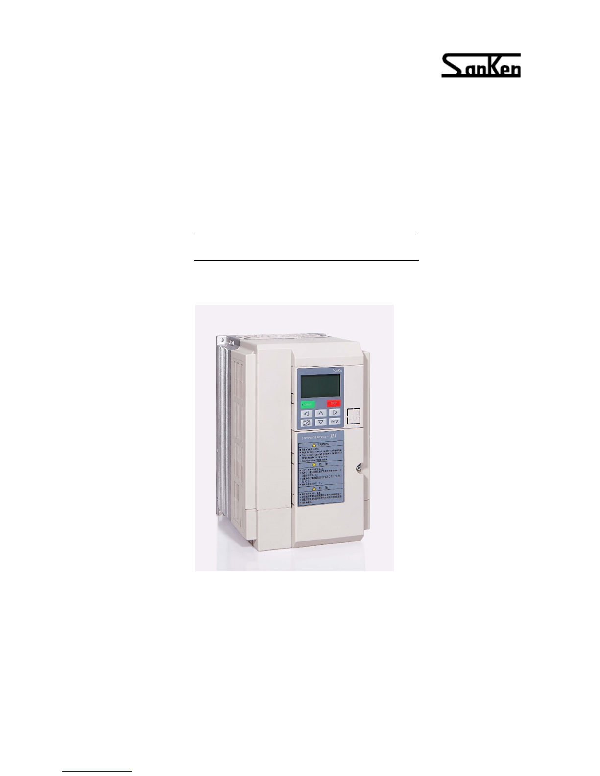
Compact Vector Control Inverter
VVVF Inverter
SAMCO-NS series
Instruction Manual (
Simple Version
)
SANKEN ELECTRIC. CO., LTD.
Warning Notification
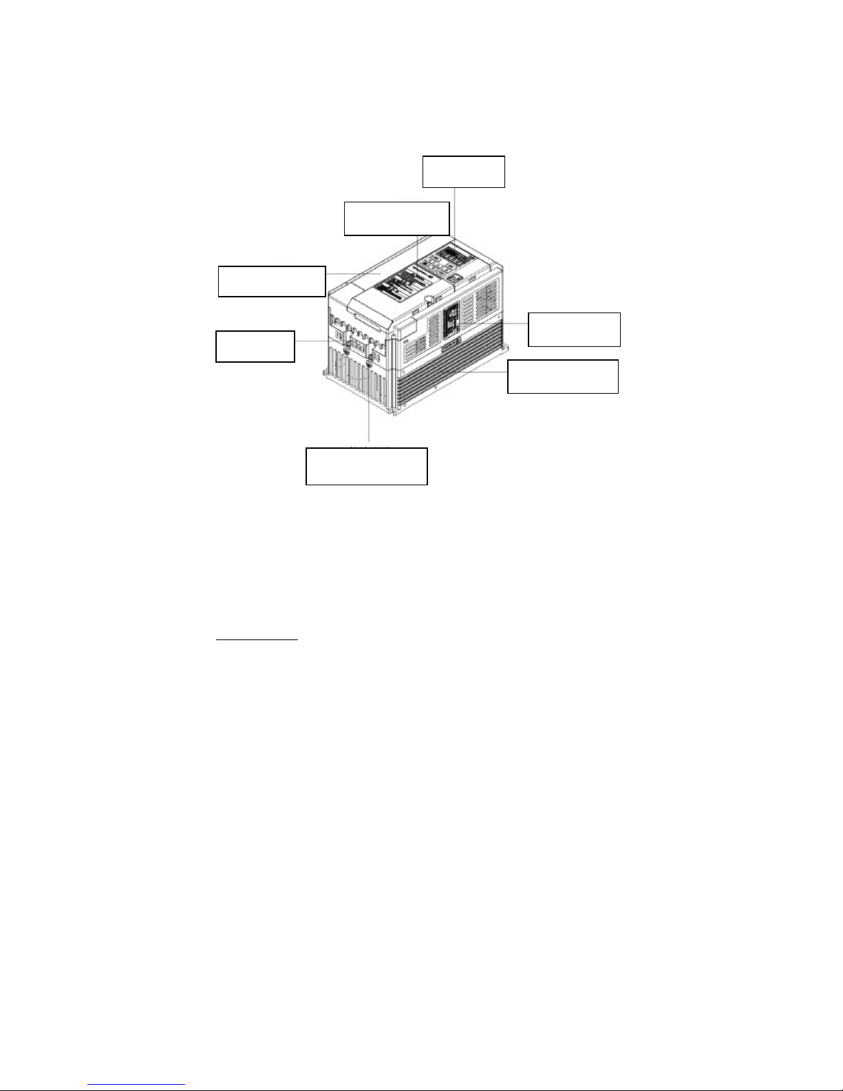
Plastic outlook frame
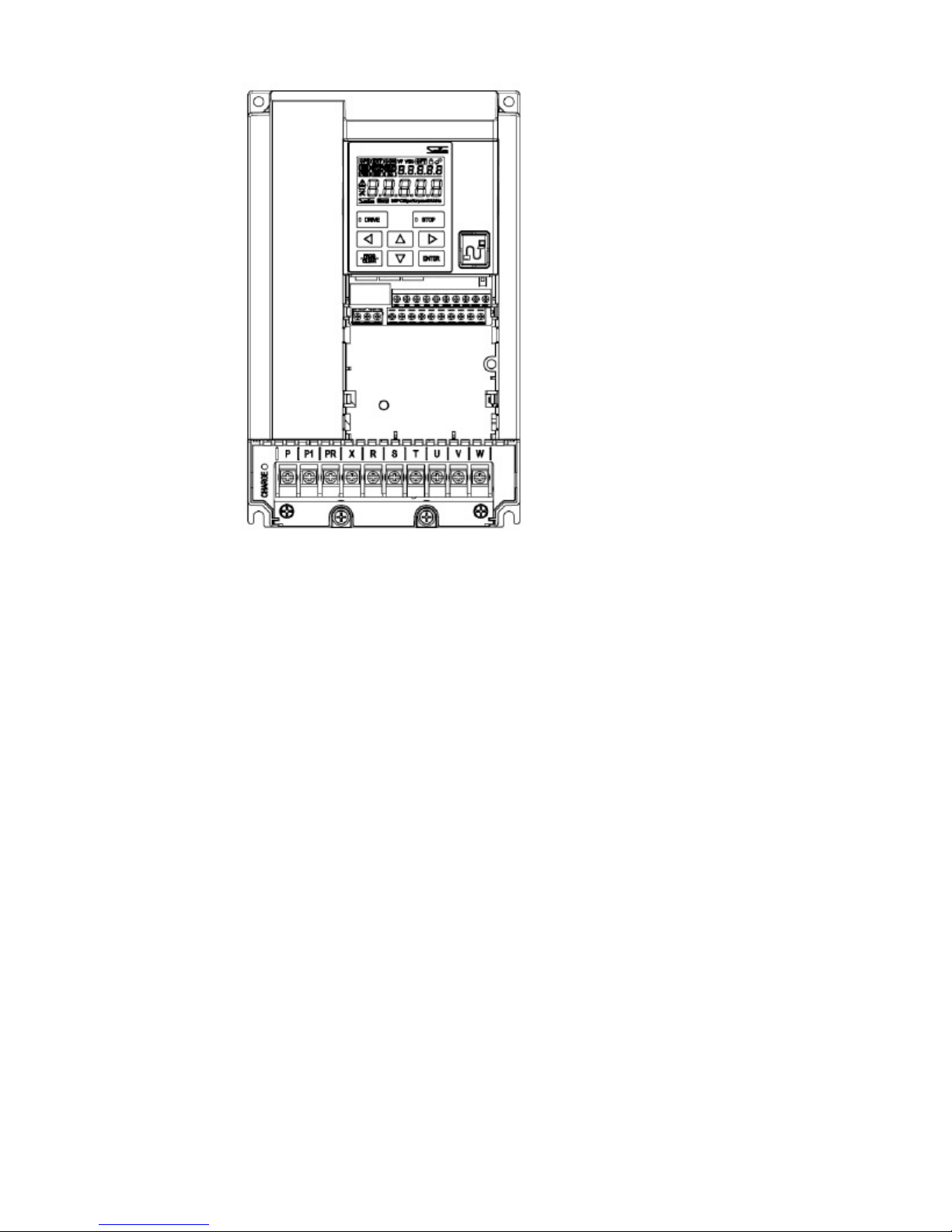
Terminal block
Grounding terminal
Checking the product and precautions on use
Checking the product
■ Product body:
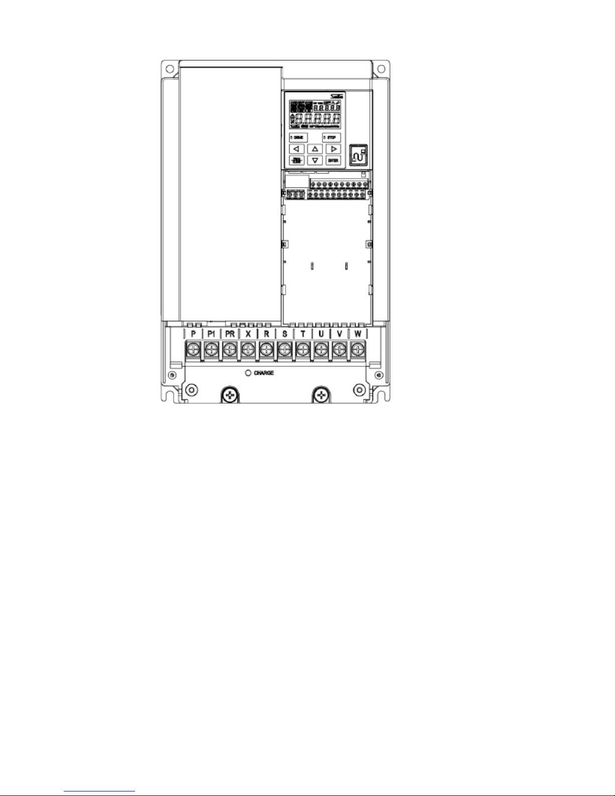
NS Vector Control Inverter Body (For example: NS-4A017-B):
LCD Display
-1-
Rating nameplate
Radiator structure
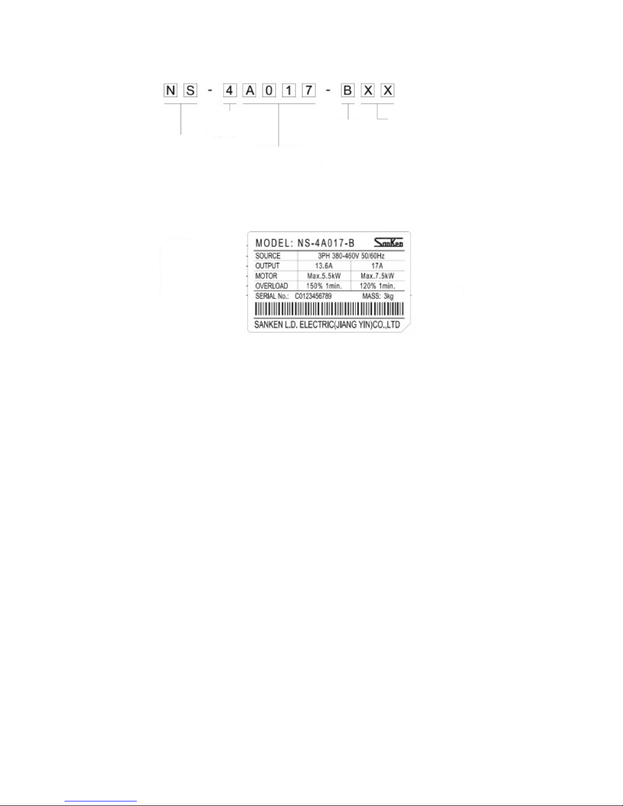
Rated Current
Load Mode
The contents of the model
Series Name
Vo ltage Class
3Ø-400V
Rating nameplate
Internal Code
B: 120% 1 Min.
A017: 17A
Capacity: 7.5KW
-2-
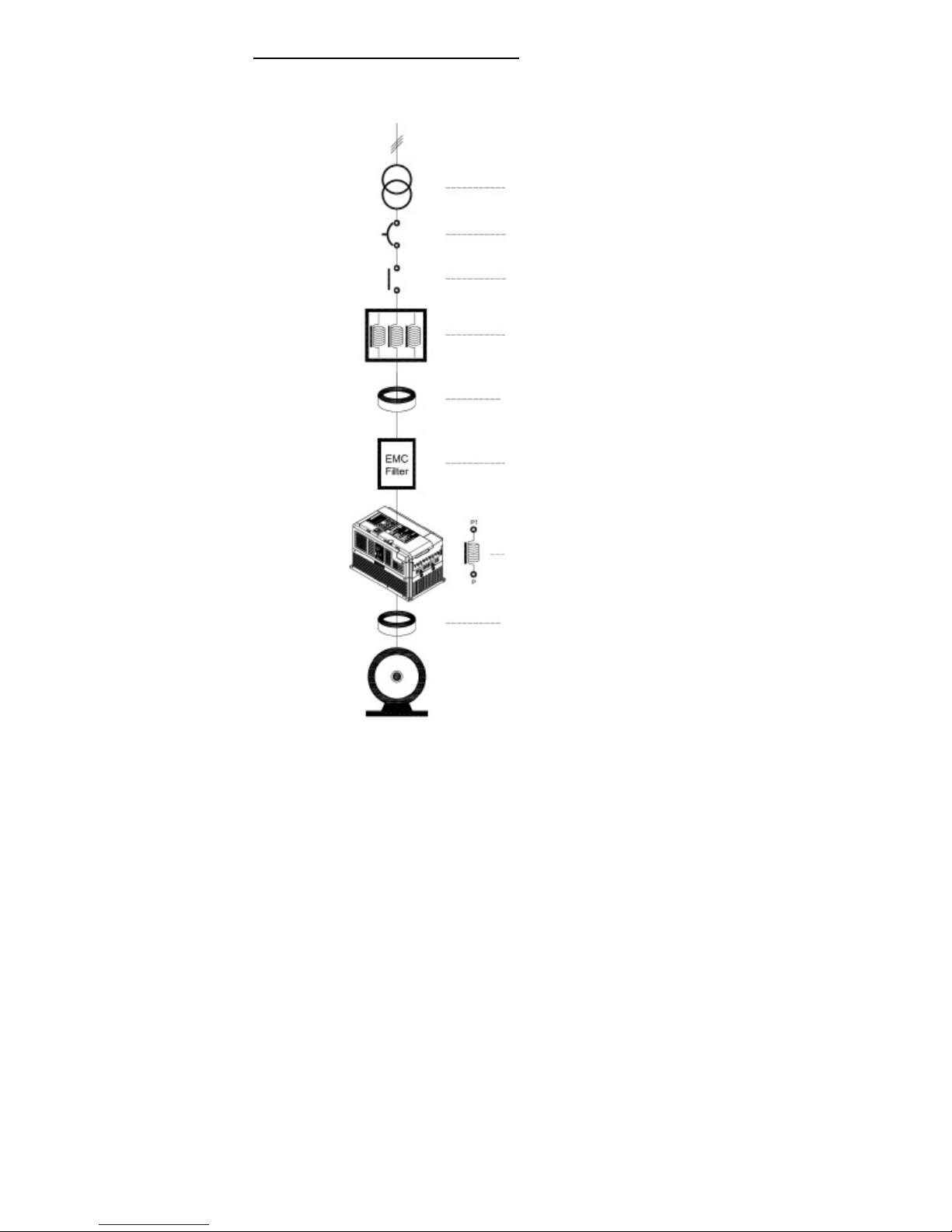
Connection with peripheral device
Draft for the connection with peripheral device
Power Supply
Input power supply transformer
Wiring circuit breaker
Or
Leakage circuit breaker
Electromagnetic contactor
AC reactor
Zero-phase reactor
Radio noise filter
/noise filter
DC reactor
Zero-phase reactor
-3-
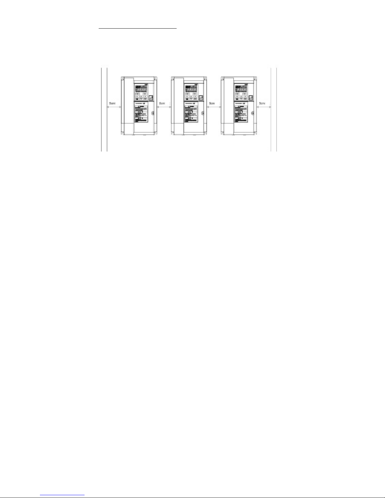
■ Installation in the side of left / right :
Pls. assure the space is above 5cm, whatever is between the inside of cabinet and the
outlook frame of Inverter, or between Inverter’s outlook frame while installed in the side of left/right
Or could be caused of not enough of heat dissipation for Inverter.
-4-
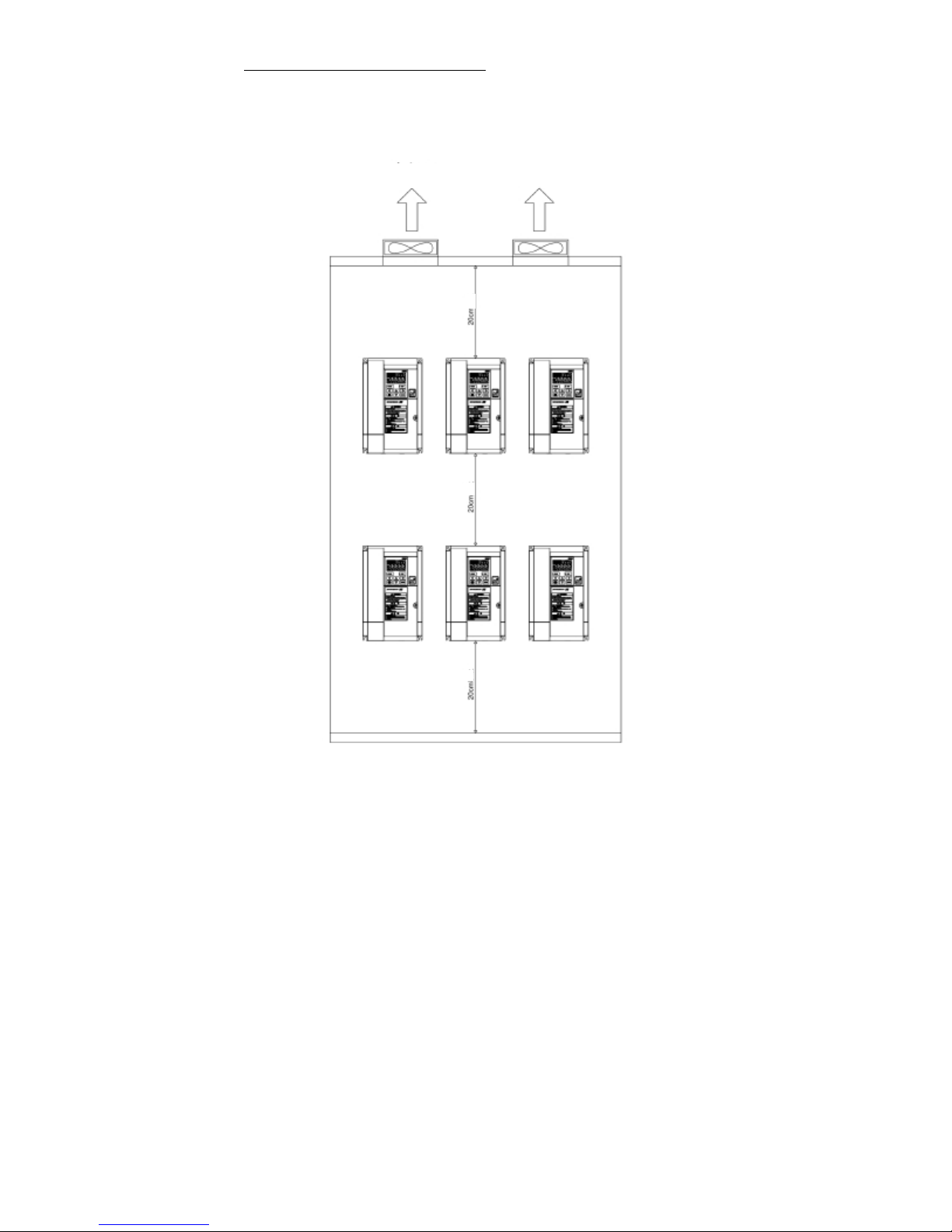
■ Installation more layers in the side of up /down:
Pls. assure the distance is above 20cm, whatever is between the inside of cabinent and the outlook frame of Inverter,
or between the Inverter’s outlook frame, and ensure the ventilation and cooling for each Inverter, or will be caused of
being not enough of heat dissipation.
Cooling Air
Cooling Air
-5-
V
entilation Fan
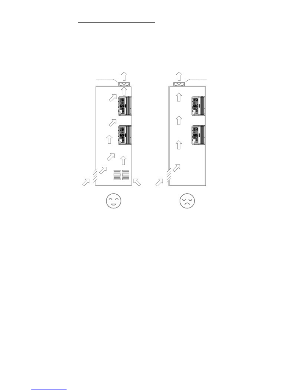
■ Installment site for ventilation fan in the cabinent:
■ Notification:
◆ When several inverters are set in a control cabinet, be sure to local the ventiliation fans properly
to allow free aire circulation.
◆ Ensure the air in the outside of cabinent flow to the Inverter’s heat dissipation route, take those heat from the
Inverter in operation away in efficient.
◆ If the ventiliation fans are located properly, t he ambient termperature will rise and affect the cooling of the Inverter.
Ven tilation Fan
Cooling Air
Cooling Air
(Correct) (Incorrect)
-6-
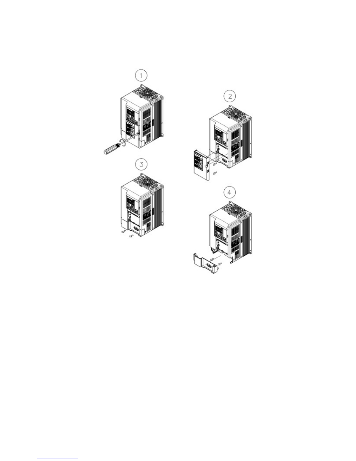
Removal and Installation of the front cover
(1)Removal of front cover (Lower)
Unscrew the M4 screws, dismantle as the below Pic.
◆
Pls. carry out this work during the main circuit wiring、control circuit wiring.
-7-
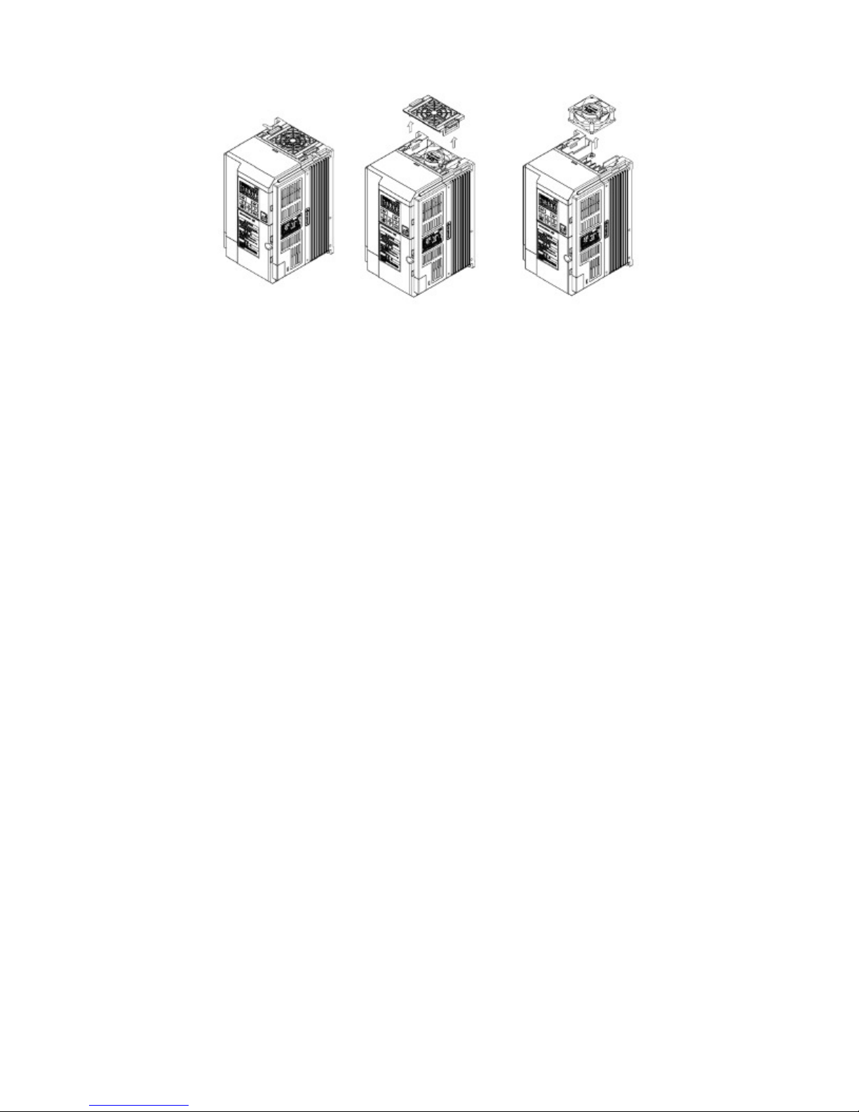
(2)Changed fan
Carry out this work only under changing fan.
(3)Installation
On installation, carrry out this work as the reverse procedures.
-8-
电位器
>5kΩ
JP2
CLEAR
ENTE R
for
10
open
after
while
CLEAR
ENTE R
取付け、運転の前に必ず取扱説明書を読み、
そ
の指示に従うこと。
通電中及び電源遮断後10分以内
はカバーを開け
ないこと。
for
10
open
after
while
CLEAR
ENTE R
取付け、運転の前に必ず取扱説明書を読み、
そ
の指示に従うこと。
通電中及び電源遮断後10分以内
はカバーを開け
ないこと。
for
10
open
after
while
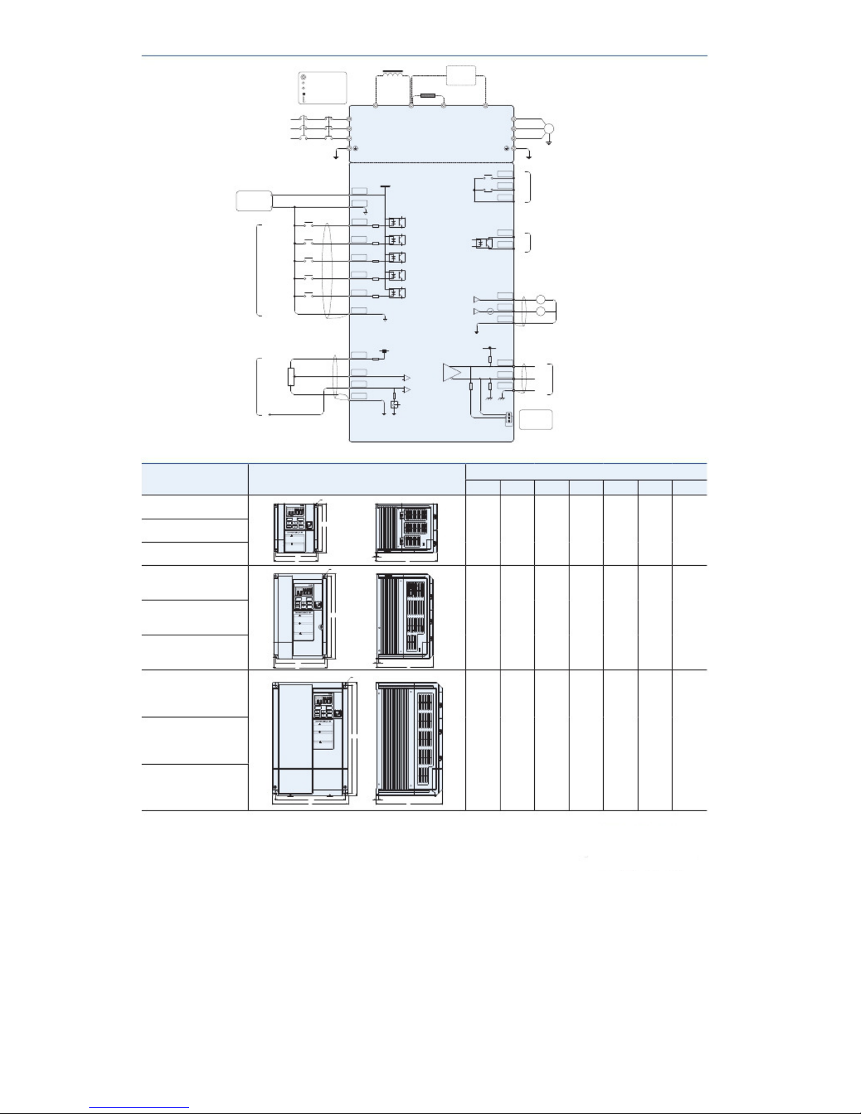
Terminal Connection Draft
Terminal in Main circuit
Input terminal
Output terminal
Communication terminal
Isolation cable
DC reactor (optional selection)
Brake Unit
(Optional)
Braking Resistor (Optional Selection)
P1 P PR X
Input Power
3Ø 380~460V
50/60Hz
MCC B
MC
R
S
T
Main Circuit
U
V
W
IM
3 phase inductive motor
User load
Load Current<150mA
24V
DCM
Digital Power
24V
FA
FB
FC
Relay contact output
Contact capacity:250V,0.3A
Factory preset:Breakdow display
Code No.:F1513
FR
RR
2DF
3DF
MBS
DI1
DI2
DI3
DI4
DI5
DCM
Control Circuit
DO1
DOE
Vout
V
Iout
Open collector output
Allowed loading:48V,50mA
Factory preset:Display in operation
Code No.:F1509
0 ~ 10V Voltage output
4 ~ 20mA Current output
Digital signal on ground
Frequency setting power 12V
ACM
Analog signal
5V
Only for potentiometer
V+
0~5V,0~10V voltage
0.3W
0~10Vvoltage or 4~20mA current
VRF
V/ I
ACM
F1002=9 Current Mode
Analog signal on ground
Terminal resistor
5G
TRA
TRB
SG
ON
OFF
Terminal Resistor
Switching
RS485 communication port
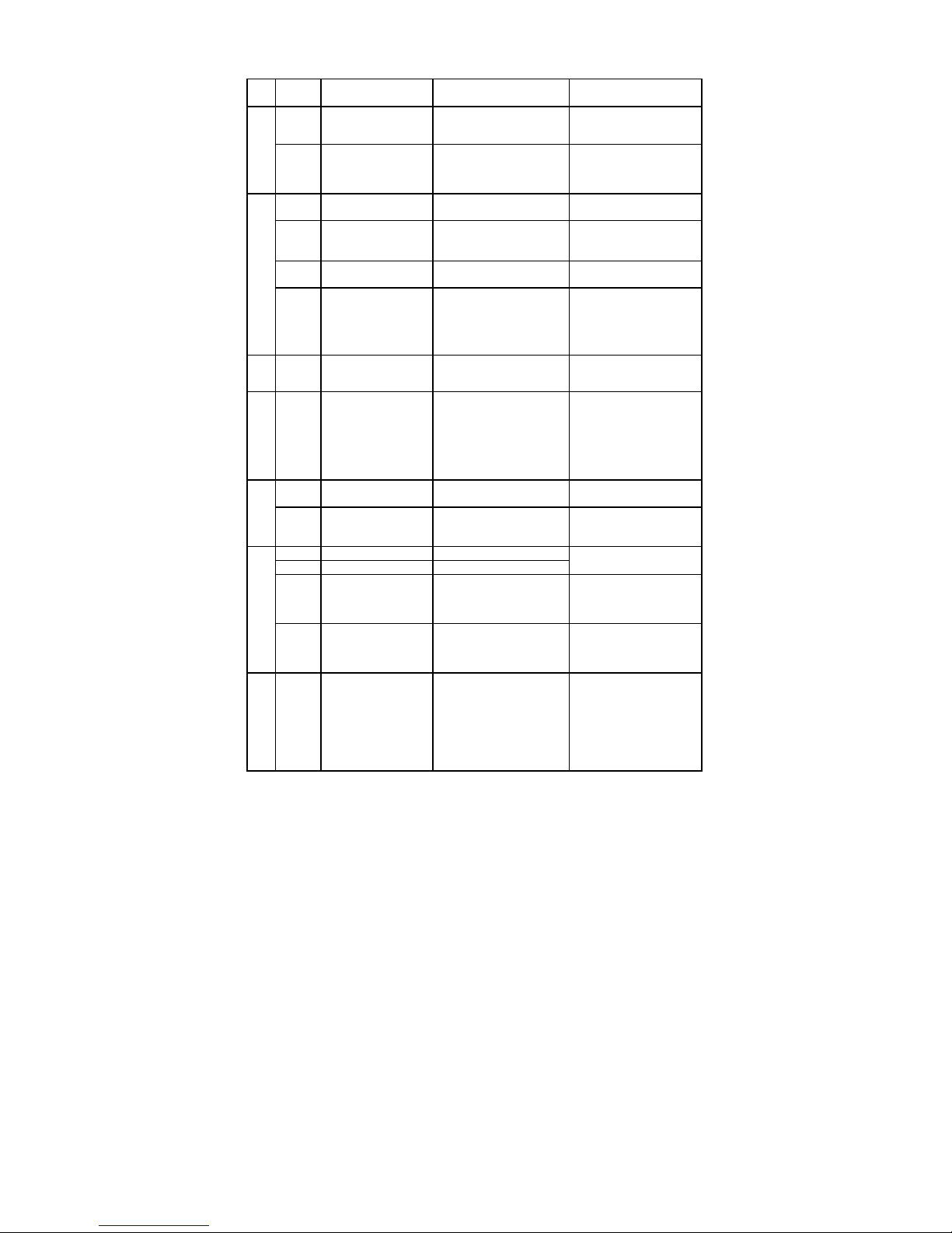
Outlook dimensions
Mode No. Outlook Frame
Dimension
H H1 W W1 D
d
t
NS-4A003-B
Ød
Easyk W ° C Mp a % r p m skVAH z
NS-4A004-B
DRIV E
STOP
PROG
WARNING
■
Riskofelectricshock.
●Readthemanualb eforein stallationand operation .
●Do
not
minutes
this
cover
isolating
power.
isappliedor
●Ensure
properearthconnection.
H1H
130
121
115
106
166
4.5
5
危险
NS-4A006-B
■有可能引起受伤,触电。
●安装运行前请务必阅读操作说明书并遵照其指示。
●通电时及切断电源10分钟内 请不要打开前面盖板。
●请正确接地。
W1
W
t
D
Ød
NS-4A009-B
Easyk W ° C Mp a % r p m skVAH z
DRIV E STOP
PROG
NS-4A013-B
WARNING
■
Riskofelectricshock.
●Readthemanual
befo r ei ns t al l ati o n
and
oper a ti on.
●Do
not
minutes
this
cover
isolating
power.
isappliedor
●Ensure
properearthconnection.
危険
■けが、感電のおそれあり。
●
●
●確実に接地を行うこと。
H1H
225
214
140
129
150
5.5
6
危险
■有可能引起受伤,触电。
●安装运行前请务必阅读操作说明书并遵照其指示。
●通电时及切断电源10分钟 内请不要打开前面盖板。
●请正确接地。
NS-4A017-B
W1
W
t
D
Ød
NS-4A024-B
Easyk W ° C Mp a % r p m skVAH z
DRIV E STOP
PROG
NS-4A032-B
WARNING
■
Riskofelectricshock.
●Readthemanualb eforein stallationand operation .
●Do
not
minutes
this
cover
isolating
power.
isappliedor
●Ensure
properearthconnection.
危険
■けが、感電のおそれあり。
●
●
●確実に接地を行うこと。
危险
■有可能引起受伤,触电。
●安装运行前请务必阅读操作说明书并遵照其指示。
●通电时及切断电源10分钟 内请不要打开前面盖板。
●请正确接地。
H1H
300
285
200
185
175
6.5
6
NS-4A038-B
-9-
Multi
-
functions terminal
Frequency setting terminal
Relay
-9-
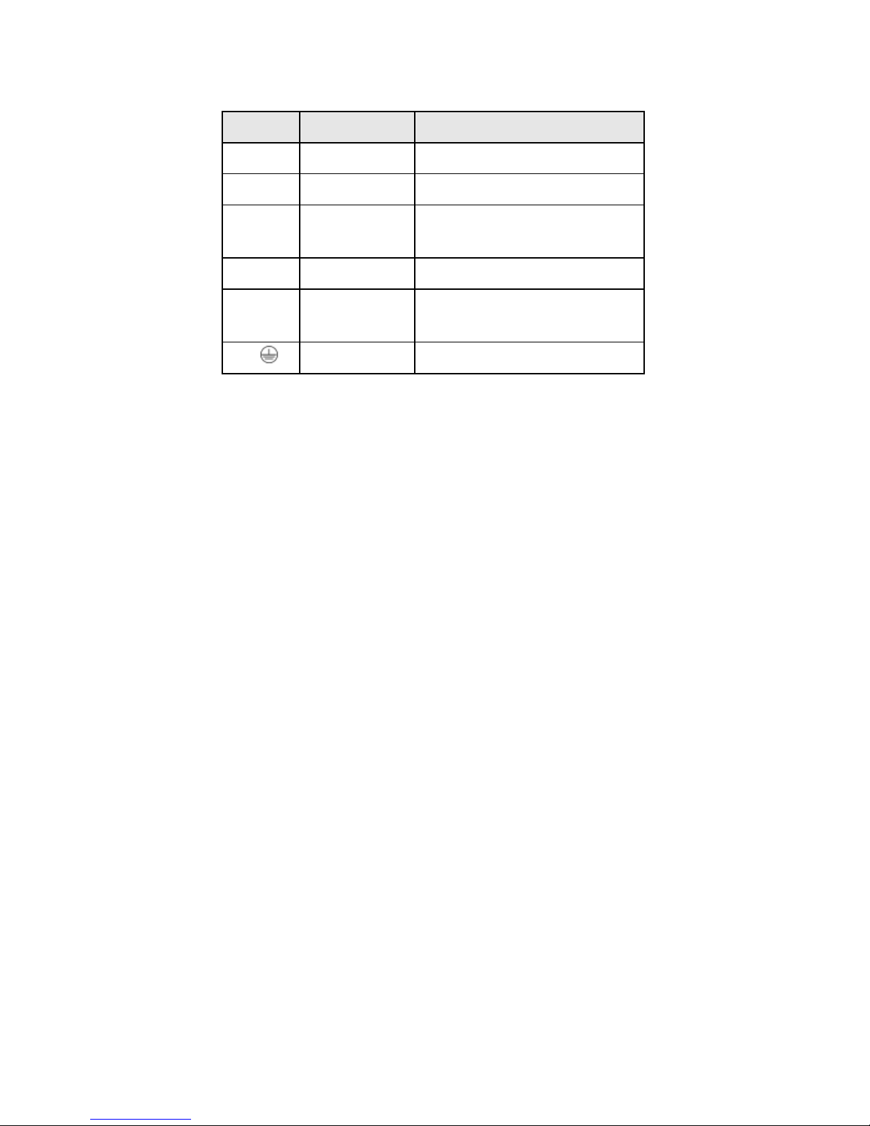
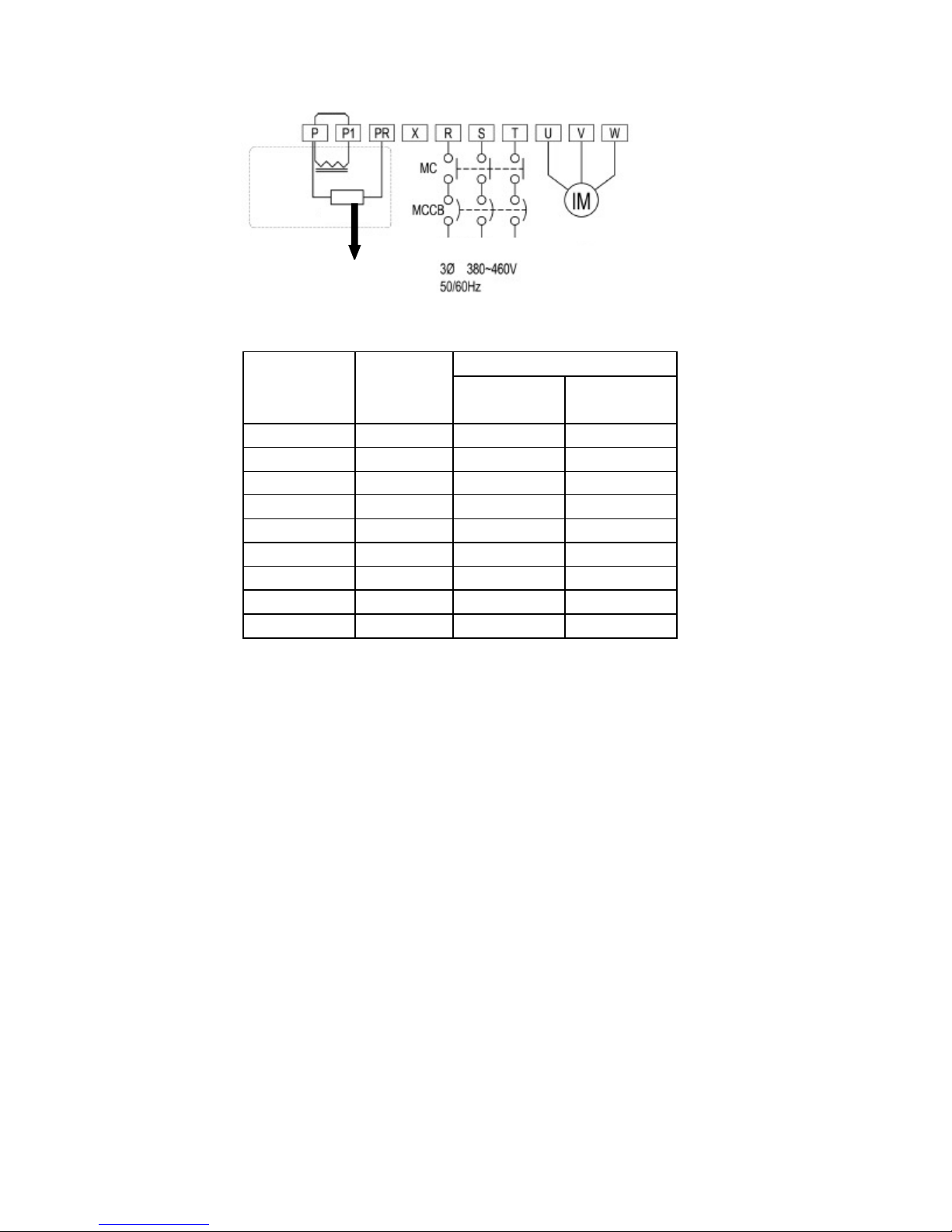
Description of Main Circuit Terminals
*1
When connecting the reactor, pls. remove the jumper
P1 and P
Composition of Main Circuit Terminals
Terminal Symbol
R,S,T Input Power Terminals Terminals connected to 3 phase commercial power supply
U,V,W Inverter output terminals Terminals connected to 3 phase induction motor
P,P1 DC reactor connection
P,PR
P,X
Brak Resistor connection
termials
DC side voltage terminals
Name Description
Terminals connected to DC reactor *1
Terminals
Terminals connected to brake resistor between P-PR
Ground Terminal Terminal for grounding of inverter casing
Terminals connected to brake unit
P is DC positive,X is DC negatitive
-10-
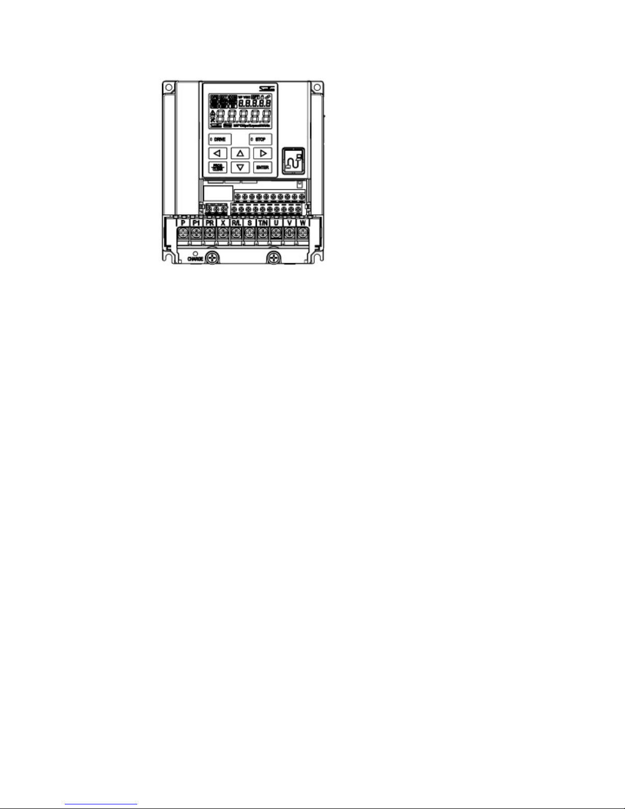
Distribution Terminal For Main Circuit
1.NS-4A003-B、NS-4A004-B、NS-4A006-B
-11-
2.NS-4A009-B、NS-4A013-B、NS-4A017-B
-12-
3.NS-4A024-B、NS-4A032-B、NS-4A038-B
-13-
(Leakage circuit brakerer)
DC
Optional Accessory
Braking Resistor
Power Supply
Motor
Main circuit terminal connection draft
Shorten Plate
Reactor
◎ Capacities of MCCB and MC and wire size
MCCB
Model No.
[A]
NS-4A003-B 5 7 20
NS-4A004-B 5 7 20
NS-4A006-B 15 7 20
NS-4A009-B 20 7 20
NS-4A013-B 30 7 20
NS-4A017-B 30 17 32
NS-4A024-B 50 25 50
NS-4A032-B 60 25 50
NS-4A038-B 70 32 60
MC(Electromagnetic contactor)
Rated Current
[A]
-14-
Rated making current
[A]

Recommend Wire Size
Note 1: The value for wires in the main circuit are for
600V
IV
PVC-insulated wires (
60 ) When the ℃
diameter
Main Circuit
Recommended wire size[mm ]
Input Wire R、S、T
NS-4A003-B 2.0 (2.0) 2.0 (2.0) 2.0 (2.0) 5.5
NS-4A004-B
NS-4A006-B
NS-4A009-B
2.0 (2.0) 2.0 (2.0) 2.0 (2.0) 5.5
2.0 (2.0) 2.0 (2.0) 2.0 (2.0) 5.5
2.0 (2.0) 2.0 (2.0) 2.0 (2.0) 5.5
P、P1
PR、X
2
U、V、W
Grounding wire
Tightening
Screw
Torque
N·m
M4 1.2 5.5
Max.
Wire size
2
mm
NS-4A013-B
NS-4A017-B
NS-4A024-B
3.5 (2.0) 3.5 (2.0) 2.0 (2.0) 5.5
5.5 (2.0) 5.5 (2.0) 3.5 (2.0) 5.5
5.5 (2.0) 5.5 (2.0) 5.5 (2.0) 5.5
NS-4A032-B
NS-4A038-B
8.0 (3.5) 8.0 (3.5) 8.0 (3.5) 14
14 (5.5) 14 (5.5) 8.0 (3.5) 14
M5 2.0 14
inverter ambient temperature is 40℃
The value in( )are for
Note 2: The maximum wire size indicates the maximum wire cross-sectional are that can be used with
the terminal block
600V bridged-polyethylened insulated wires(90℃)
-15-

※
1
The above brake resistor is selected by the max. use rate
10%ED.
Model No.
NS-4A003-B 700Ω or above
NS-4A004-B 700Ω or above
NS-4A006-B 320Ω or above
NS-4A009-B 160Ω or above
NS-4A013-B 120Ω or above
NS-4A017-B 80Ω or above
NS-4A024-B 60Ω or above
NS-4A032-B 40Ω or above
NS-4A038-B 40Ω or above
External brake resistor(Recommend) External brake resistor (limit value)
Resistor value Capacity
100W
100W
200W
400W
600W
800W
1000W
1500W
1500W
※ 1
Resistor value Capacity
420Ω or above
420Ω or above
190Ω or above
130Ω or above
80Ω or above
52Ω or above
38Ω or above
32Ω or above
32Ω or above
-16-
300W
300W
300W
500W
800W
1100W
1500W
1800W
1800W
※ 1
Recommend wire size
:
0.75[
mm
2
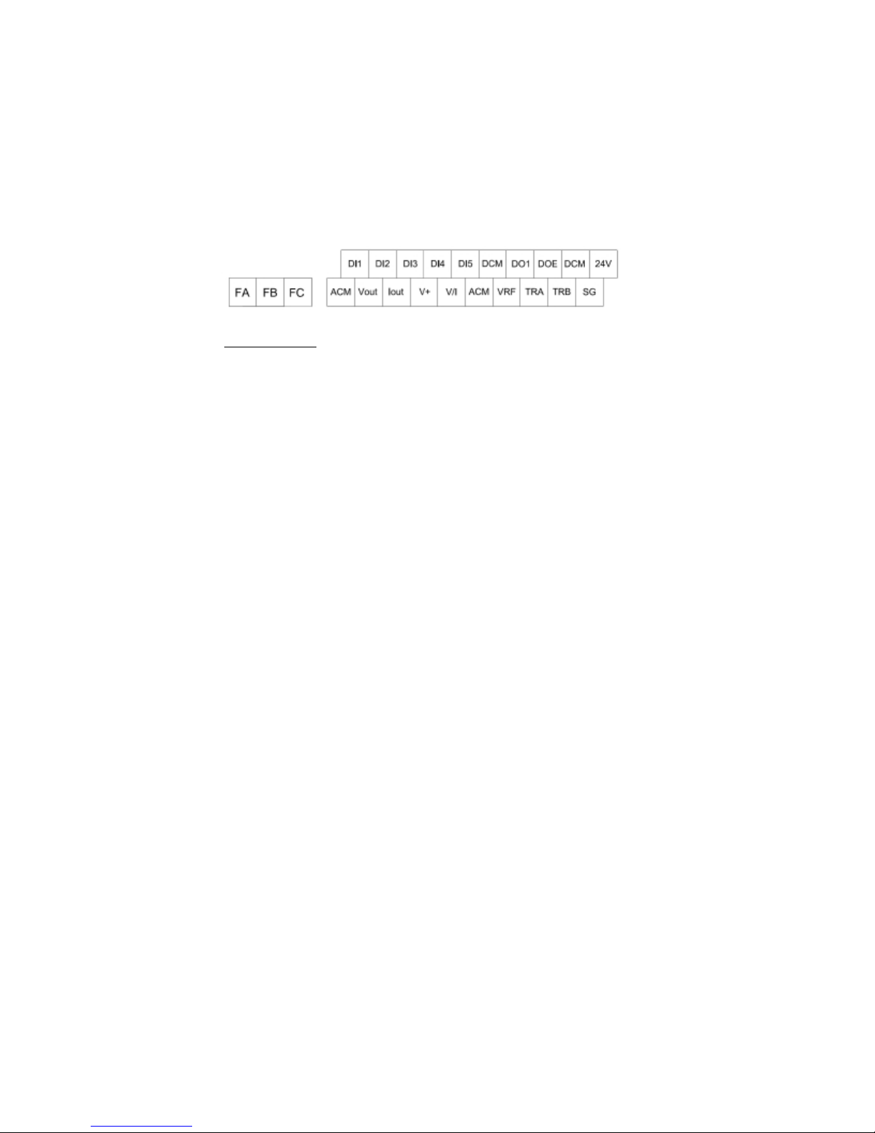
Composition of Control Circuit Terminals
Wire size
Terminal screw diameter:M3
]
Tightening torque:0.5[N•m]
The arrangement of control circuit terminals is as shown in the following
■ Most Attention:
▲ Don’t input stronger voltage to the control terminal! Or control board burnt
▲ Pls. move the control calbe far away to power cable in avoid of intevenue or noise.
-17-
Function of control circuit terminals
nput and
power supply
5mA
Power supply for customer
Max. allowable output current
tion through
selected on site for Inverter side
whethe connected
Type Terminal
Symbol
Multi function input
DCM
DI1
~
DI5
ACM
+V
Analog value input
VRF
V/I
Power
Supply
24V 24V client’s power supply DC24V
Multifunctional output
DO1
DOE
Analog value output
Vout
Iout
Communication terminals
TRA
TRB
SG
JP2 Terminal resistor switching
Contact output
FA
FB
FC
Terminal Name
Digital signal common
terminals
Multi-Functional input
terminals
Analog signal common
terminals
Frequency setting power
supply
Analog voltage input
terminal
Analog voltage or input
Current terminal
Multifunctional collector
output terminals
0~10V voltage output
terminal
4~20mA current output
terminal
RS485 communication sending/receiving (+) RS485“+” signal
RS485 communication sending/receiving (-)
RS485 common
communication terminals
selected
Abnormal alarm signal
Output and multifunctional
Contact output
Function Description
Common terminals for digital i
output signals and 24V
Signals valid while the short
-circuited between DIX and
DCM
Common terminals for analog
Input and output
Connected to a potentiometer
of 5kΩ,0.3W or above
Setting frequency through input
voltage
This way of current/voltage
switching independely
Sending signals for func
selected fuction code.
voltage output for setting
internal signal
Current output for setting
Internal signal
RS485“-” signal
SG terminal for connected
communicated equipment while
RS485 on communication
The selection of
100Ω terminal resistor
The default of that terminal is
Inverter warning and stop contact
output signal, which is selected the
others function through setting
function code of F1513、F1504
Rated Specification
Total current consumed:
100mA or less
Input resistor:about 6.6kΩ
When short-circuited:about 3~
Total current consumed:100mA or less
DC 10~12V
※ it can not be connnected to any
Element other than the potentiometer
Input resistor:about 34kΩ
Max. alllowed voltage:DC12V
Vo ltage input is the same spec. as
VRF current input resisto: about
250Ω, Max.allowed current:30mA
for DC 24V 150mA
Open collector output
Allowable loading: DC48V
、50mA
0~10V
4~20mA
Communication speed:1200-57600bps
Total Length:500m
※
Communication equipment side
Single-end earthed
OFF Resistor Open
ON Resistor Connection
Contact capacity: AC250V/0.3A
The selection of warning contact
Normal:FA-FC opened
Abnormal:FA-FC closed
-18-
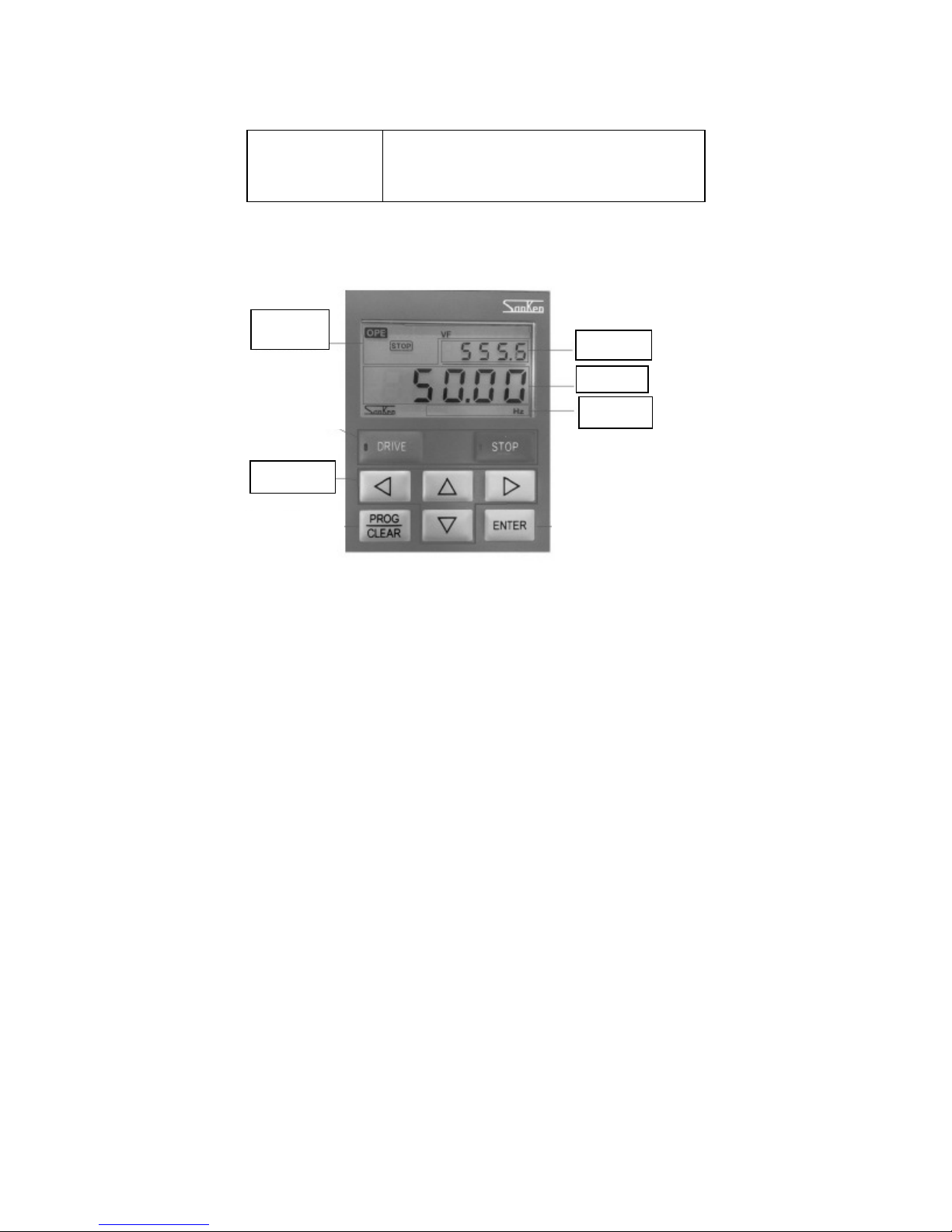
LCD Operation Panel
Information
Status Display
Name and Function for each part of panel
Inverter status during operation /stop
<Frequency> <Output Current> <Roatation Speed> <load factor>
<Output Voltage> <Pressure Value>
Inverter Condition
Direction Key
Sec ond ary sc ree n
Primary screen
Units
Description:
Primary Screen 5 digit 7 segment LCD : Shown the following data through changing Left/Right direction key or
parameters setting, “Current operation frequency、Output current、RPM、Load factor、Output voltage、Voltage value、
Set value and warning content”.
Secondary Screen 5 digit 7 seg ment LCD: Shown t he data of “Current output voltage、DC Voltage、Active power、Apparent
power、Radiator temperature and the others content” by setting parameters.
“Units” is only for primary screen, mainly display “Frequency(Hz)、Output current(A)、Speed roation(Rpm)、Load factor(%)、
Output voltage(V)、Pressure value(MPa)”.
-19-
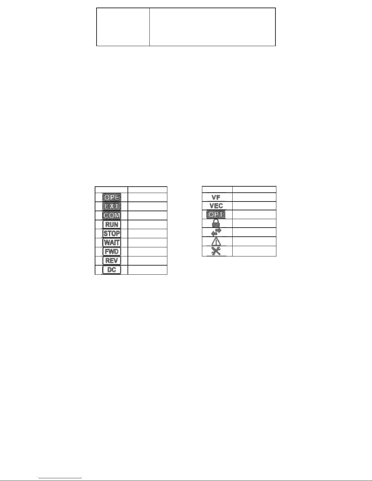
List of each status description
Function Code Display Code No. and data
F1001, and
Operation panel display mode:
Prmary screen and Secondary screen classified by【Status Display】and【Function Code Display】
two Modes, and switched that through【PROG】Key
For example: Push【PR/CL】Key, secondary screen shown
Primary screen show the value of F1001
Push【ENTER】Key, Primary screen flashing, and revise
data through【∧ 】、【∨ 】、【<】、【>】
Push【ENTER】Key, parameters setting successfully
Status display mode for Inverter statis monitor、Alarm display、Output frequency setting and run/ stop
Inverter and so on.
5-3-1 Version Display
Turn on the power supply in a while, Primary monitor show the Inverter Version.
Such as: VER 1.00 as the below:
U0100
LCD Inverter Status Information
Display content Description
Operation panel control
External terminal control
Remote communication control
Operation
Stop
Standby
Forward
Reverse
DC braking
Inverter status mode
Display Inverter status.
Display Inverter each status in operation and stop.
Display Content Description
V/f control mode
Vector control mode
Operational parts
Parameters locked
Communication
Inverter alarm
Inverter brake-down
-20-
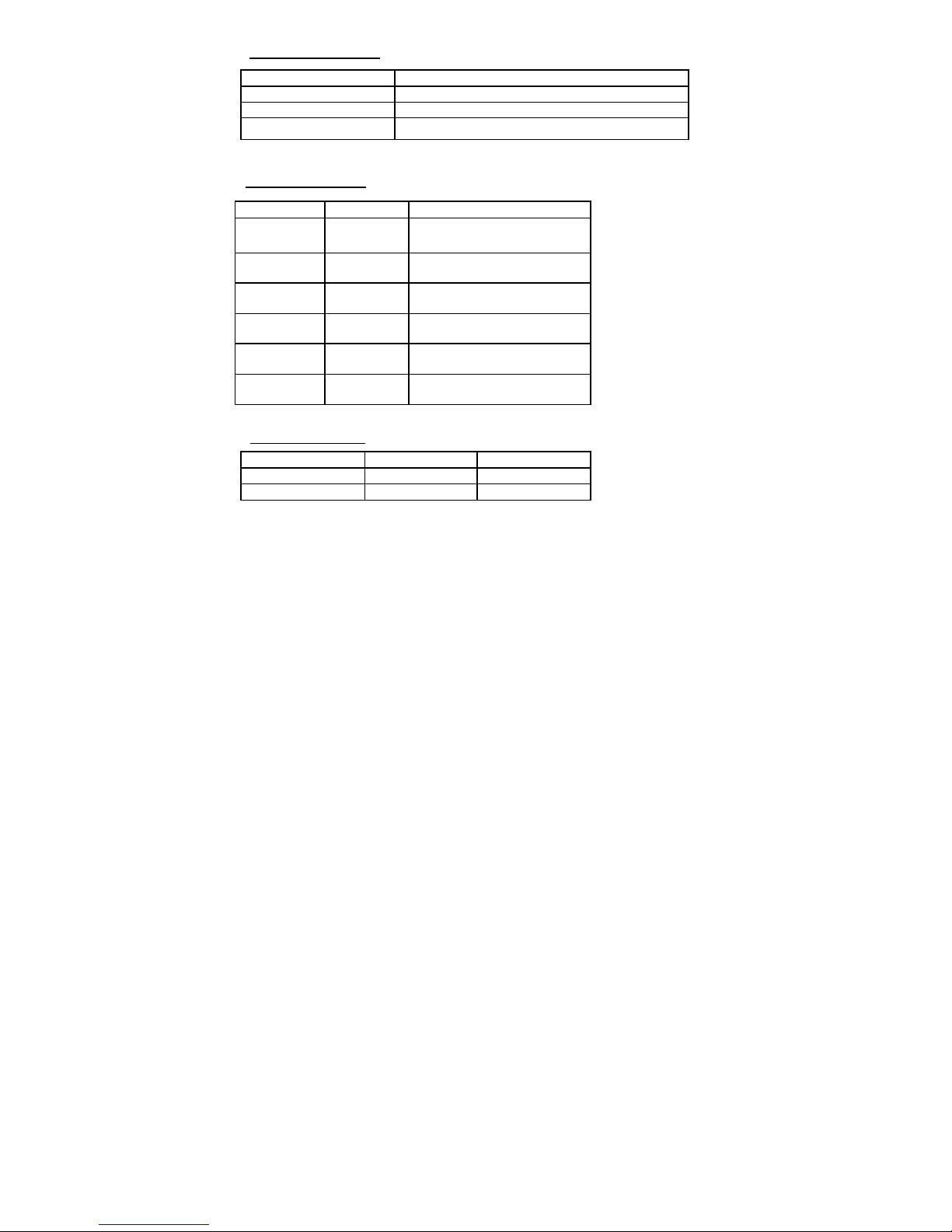
表
5-4
转速显示内容
Speed display content
Operation mode display
Action status
Stop
Operation
Fault
Operation lamp “off”, Stop lamp “on”
Operation lamp “on”, Stop lamp “off”
Operation lamp “flashing”, Stop lamp “flashing”
Display content
Monitor mode display
Display content
Frequency Hz
Output current A Output Current
Rotation speed rpm Speed
Load factor % Load factor
Unit
7-Segments LCD display
On operation:That is output frequency
At stop: That is setting frequency
Output Voltage V Output voltage
Pressure MPa Pressure feedback
Motor control mode
V/f control mode
Sensorless vector control Mode
Operation
Motor synchronized speed
Motor estimated speed Set speed
Stop
Set speed
During Inverter status monitor display, press【<】key or 【>】key one times, switching the display content
on the primary screen at one times, the display content on primary screen can also be switched by the function
code. As for the details, pls. referring the function code: F2303.
When the alrarm is stopped, alarm type will be shown on the primary screen.
※ During alarm display, even press【<】Key or 【>】Key, it can’t be switched the display on primary screen.
※ It can be switched to the function code display mode through press【PROG】key during alarm display.
-21-
For Example
:
From
5Hz to 45Hz
For example: set
F1414=10
inished, and then back
g,
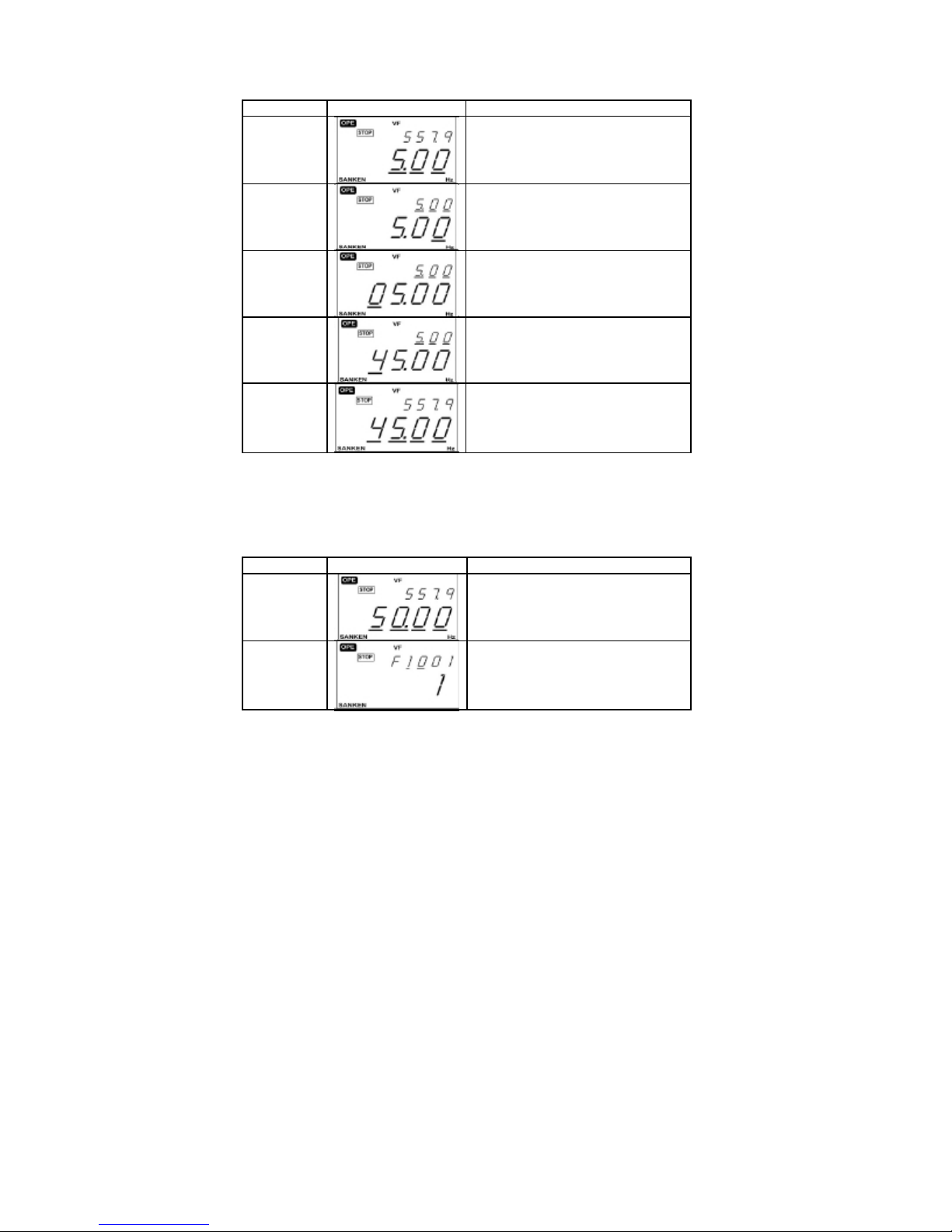
During status monitor display, frequency setting as the below method whatever is on operation or at stop
Operation
Display
Description
Status monitor display(Frequency display)
【ENTER】
Input value display the last right digit.
(Revise the value while this digit flashing)
※( 1)
【<】*3
【∧ 】*4
【ENTER】
Press 【<】key one time, flahsing position will move to
the left on one digit.
Press【<】key 3 times,ten digits flashing.
(※1)
Press【∧】key every one time, value added 1
Press【∨】key every one time, value minus 1
Press【∧】key 4 times, ten digits value will be changed
to “4”
Press【ENTER】, frequency setting f
to the status monitor interface.
※ 1 While no needing the frequency setting,press【PR/CL】key return to status monitor display Mode.
Basic operation
Function code setting
Normal operation used for the changing the value of function code.
Operation Display
【PR/CL】
Description
Status monitor display(frequency display)
Press【PR/CL】key show function code input
interface.
Second display parameters number10 flashin
and the value could be revised.
-22-

※
1 When no needing to set the new value, return to parameter number setting interface through
【∧ 】*4
【>】
【∧ 】*13
【ENTER】
【∧ 】*9
【ENTER】
【PROG】Key.Parameter numble in the second monitor flashing.
Confirmation
Some function codes need to re-confirm for the prevent of wrong operation which could be caused
of data re-written.
For example:set F1001=10
Press【∧】key, changing number to 14, second display
parameters number 14 flashing, may be revised again.
Press【>】key switch to parameters number revised
mode, second display parameters number 01 flashing,
the value could be revised
Press【∧】Key, parameters number revise to 14,
Seondary monitor parameters number 14 flashing,
may be revised.
Press【ENTER】Key, switch to parameters modify mode,
primary monitior F1414 value 1 flashing,
may be amended.
Press【∧】key, revised the parameters value to
10, primary monitor F1414 revised value 10 flashing,
and can be amended.
Press【ENTER】key, confirm the changing value,
secondary monitor parameter number 14 flashing,
may be modified. Parameter value revised finished.
.
Operation Display
【PR/CL】
Description
Status monitor display(Frequency display)
Press【PR/CL】key show display function code input
interface, secondary monitor paramerter no: 10 flashing,
may be ameneded.
-23-

※
1
ready
flashing, press
【
PROG/
CLEAR
】
key return to function code selection interface
while
alue
key, primary monitor show the setting value, secondary
【ENTER】
【∧ 】
【ENTER】
【∧ 】
【PR/CL】
found out some wrong on operation, and interrupt the action of input.
※ 2
Press【PROG/ CLEAR】key could also return to status monitor display mode interface.
Primary monitor parameter value 1 flashing, that is
meaning to be revised the current value.
Press 【∧ 】key, to change the revised v
to 10
Press 【ENTER】
monitor show flashing, remind to the final
confirmation for the setting value.(※1)
Press【∧】again, new setting confirmed, and display
return to the function code selection interface. (※2)
Press【PROG】key,return to status monitor
display interface.
5-5 Special Functions
5-5-1 Changed code display function
Due to the data in the current function code is different with the factory presets and user’s initial
value, therefore, it displays the function code for which data values have changed.
This is an effective function for finding out the difference between the current function code and
factory presets or user’s initial value.
Repair and maintenance functions such as confirmation of codes etc, can be easily executed.
-24-

For example:
D
isplay the disfference with the factory pr
eset
-25-
】
key, starting to search thee function code, that
】
Operation Display
【ENTER】
【∧ 】/【∨
Or digit keyboard
(Optional selection)
【ENTER】
Searching Ending
【∧ 】/【∨
Or
Or
【PR/CL】
Description
Select function code F1602
(Changed code display function)
Press【ENTER】Key, entered into the
parameters setting condition.
Press【∧】/【∨】or digit keyboard, select 1.
F1602=1 , this will compare the factory presets with
current function code data.
Press【ENTER】
which is the value changed compared with the factory
presets.
Primary monitor 7 segments display F
Searching ending, secondary monitor display the
changed code, and flashing.
No changed code found, secondary monitor display
on flashing, primary monitor show the current value for
related parameter.
Browse the page of different parameter code
and its current value through【∧】/【∨】key.
Press【PR/CL】Key, back to the selection
of function code interface.
ind
in flashing.
End

Alarm status confirmation
Alarm status confirmation is the function shown the Inverter status in case of a Alarm.
It could be confirmed for alarm status during the latest 5 times through function code F1806~F1810
New alarm happened, the easliest alarm will be deleted. That is latest alarm in F1806, and the earliest
one in F1810.
For example: While the latest alarm occurs, the confirmation for Inverter’s status.
Operation Display
Or
【ENTER】 Or
【∧ 】/【∨ 】
【PR/CL】
Or
Description
Select function code F1806
(Alarm status confirmation)
Press【ENTER】,alarm name in1
Monitor show the current display alarm name If
the alarm isn’t recorded, display
Alarm saving, press【∧ 】/【∨ 】, switching the
shown content. Secondary monitor display the name
(※ 1), primary monitor show the
value during alarm happened (※ 2)
Press 【PR/CL】Key,which is back to the
selection of function code
st
Monitor . 2
nd
Function code F1805=9 is set. all alarm record will be deleted. At this moment, the data records in
F1806 t~ F1810 will be erased.
-26-

※
2 The value displayed is the status before the occurrence of an alarm. Therefore, if an alarm is caused by transient over
-
current, over
※ 1:Display name as below:
Display Content
Alarm Name -
Output Frequency Hz
Output current A
Output Voltage V
Dc Voltage V
Output Power kW
Radiator Temperature ℃
Unit
voltage he stored value is the differ ent from the current value、voltage value on the alar m.
Monitor display list
Monitor Display
The Data is on flashing during initialization.
During initialization of user data, the data is displayed flashing.
The data is on flashing on the confirmation of user data.
Display shown that needs to reconfirm the operation by function code.
During search of the function code, of which user data is discrepant from
the default settings, the display is on flashing status.
The display is flashing during the trasfer of host function code data to the
operation panel.
During the trasfer of the operation panel function code to host, it is displayed flashing.
It is displayed flashing, while the desired data can’t be found through the function code
search and alarm history record.
Indicates auto turning.
Description
-27-

Function code are functionally classified into “function blocks”
Function Code
Representation and Description of Function Code
By changing the function code, Inverter action can be changed
Function
Basic operation function
F10xx~F13xx
Inpu/output-related function
F14xx~F15xx
System-related functions
F16xx~F18xx
Special function
F19xx~F20xx
Scheduled opertion functions
F21xx~Fxx
Display function F23xx F23xx LCD display function
PID fucntion
F30xx~F33xx
Water supply fu nction F34xx F34xx Water supply fu nction
Communication functions
F40xx~F41xx
Motor parameter F5xxx F5xxx Motor parameter
Vector Co ntrol F60xx F60xx Vect or Control Function
Function Block
F10xx
F11xx
F12xx
F13xx
F14xx Input function
F15xx Output function
F16xx System function
F17xx Protective function
F18xx Information function
F19xx Energy-saving function
F20xx V∕f characteristics
F21xx Multi-speed function
Fxx Scheduled operation function
F30xx Basic PID1 Function
F31xx Basic PID2 Function
F32xx Combined function of PID1,PID2
F33xx PID control parameter reading
F40xx Serial communication functions
F41xx MODBUS communication function
Function Block Name
Basic function
Starting• Braking function
Display function
Auxiliary functions
-28-

ol)
1
1
1
Function Code List
Basic Operation Function F10xx~F13xx
Runing Function F10xx~F13xx
Code Function Name Data Content
1001 Motor control mode
selection
1:V∕f Control Mode
2:Speed Control(Speed sensorless vector contr
3:Speed Control(Speedy sensor vector control)
10:Auto tuning mode 1
11:Auto tuning mode 2
40:V•f separation control
Setting
resolution
1
Factory
preset
1st Speed frequency
1002
Setting selection
1003 V∕f patten selection
1004 Torque boost
1005 Base Voltage
1006 Base Frequency 0.1~600Hz
1:Operation Panel
2:External analog VRF voltage(0~5V)
3:External analog VRF voltage(0~10V
or potentiometer)
4:External analog V/I Voltage(0~5V)
5:External analog V/I voltage(0~10V
or potentiometer)
9:External analog V/I current(4~20mA)
11: External analog VRF voltage+V/I voltage
14: External analog VRF voltage-V/I voltage
15: External analog V/I voltage-VRF voltage
18: External analog VRF voltage+V/I current
19: External analog VRF voltage-V/I current
20: External analog V/I current-VRF voltage
21: Terminal block stepping
22: Communication
25: Pulse Train Input
26: External analog VRF forward /reverse r un
operation(0~10V、5V reference)
27: External analog V/I forward/ reverse run
operation(0~10V、5V reference)
1:Linear patten
2:Square-law decreasing patten (weak)
3:Square-law decreasing patten (strong)
0~20%(Maximum voltage ratio)
400V series 0:No AVR
50~460V
-29-
1
1
0.1%
1V
0.01Hz
※ 1
※ 1
※ 1

60
1
5
1% 50
1% 50
shaped acceleration
1% 0
1% 50
1% 50
1% 0
Code Function Name Data Content
1007 Upper frequency limit 5~600Hz
1008 Lower frequency limit 0.05~200Hz
1009 Carrier frequency
adjustment
1010 Acceleration/
Deceleration Curve
Reference frequency
1011
for acceleration
/deceleration
1012 1st acceleration time 0~6500 sec.
1013 2nd acceleration time 0~6500 sec.
1014 3rd acceleration time 0~6500 sec.
1015 4th acceleration time 0~6500 sec.
1016 1st deceleration time 0~6500 sec.
1017 2nd deceleration time 0~6500 sec.
1018 3rd deceleration time 0~6500 sec.
1019 4th deceleration time 0~6500 sec.
1020 JOG acc./dec.time 0~20 sec.
1021 JOG frequency 0~60Hz
1022 1st start of S-shaped
Acceleration
1023 1st end of S-shaped
Acceleration
1024 Gradient of middle of
1st S-
1025 1st start of S-shaped
Deceleration
1026 1st end of S-shaped
Deceleration
1027 Gradient of middle of
1st S-shaped
Deceleration
5~130
1:Random Soft Carrier Mode 1
2:Random Soft Carrier Mode 2
3:Random Soft Carrier Mode 3
4:Random Soft Carrier Mode 4
1:Linear
2:S-shaped
3:Reduction of acceleration/deceleration
1~120Hz
0~200%
0~200%
0~100%
0~200%
0~200%
0~100%
-30-
Setting
resolution
0.01Hz
0.01Hz
1
1
0.01Hz
0.1 sec.
0.1 sec.
0.1 sec.
0.1 sec.
0.1 sec.
0.1 sec.
0.1 sec.
0.1 sec.
0.1 sec.
0.01Hz
Factory
preset
0.05
※ 1
※ 1
※ 2—1
※ 2—2
※ 2—3
※ 2—4
※ 2—5
※ 2—6
※ 2—7
※ 2—8
0.1

1% 50
1% 50
1% 0
1% 50
1% 50
1% 0
1
0
1
1
Code
1028 2nd Start of S-shaped
1029 2nd End of S-shaped
1030 Gradient of middle of 2nd
1031 2nd Start of S-shaped
1032 2nd End of S-shaped
1033 Gradient of middle of
1034
1035
1036
1037 Terminal block stepping
1038 Terminal block stepping
1101 Operation command selection
Function Name
Acceleration
Acceleration
2nd S-shaped acc.
Deceleration
Deceleration
2nd S-shaped dec.
1st speed frequency selection A
1st speed frequency selection B
1st speedy frequency selection C
Frequency varied
Frequency clear
Data Content
0~200%
0~200%
0~100%
0~200%
0~200%
0~100%
1: Operation Panel
2: External analog VRF voltage(0~5V)
3: External analog VRF Voltage(0~10V
or potentiometer)
4: External analog V/I voltage(0~5V)
5: External analog V/I voltage(0~10V
or potentiometer)
9: External analog V/I current(4~20mA)
21: Terminal block stepping
22: Communication
25: Pulse train input
26: External analog VRF forward/reverse run
(0~10V 5V Reference)
27: External analog V/I forward/reverse run
(0~10V 5V Reference)
0.1~10Hz/sec
0:Clear No(Frequency Maintain)
1:Power OFF clear
2:Stop Clear
1:Operation Panel
2:External Terminal
3:Communication
4: External Terminal (Three Wired)
Setting
resolution
1
0.1Hz 2.5
1
1
Factory
preset
1
1
1102 Starting Method
1:Starting frequency
2:Flying Start
3:Starting frequency after DC braking
-31-
1

1
0
0
0
5
0
1
1
1
1 5
Duty cycle of brake resistor
Discharge resistor on signal
1
Code Function Name
1103 Starting frequency
1104 Operation start frequency 0~20Hz
1105 Start delay time
1106 Start standby time
1107 Start standby frequency 0.05~60Hz
1108 Restart after momentary
Power failure
1109 Direction of rotation of
Motor
1110 Direction of rotation of
Motor (Setting through
Operation panel)
1111 Braking method
1112 DC braking start frequency
Data Content
0.05~60Hz
0~5 sec.
0~120 sec.
0: Do not start
1: Restart
2: Compensation for momentary power failure
1:Forward and reverse run
2:Forward run only
3:Reverse run only
1:Forward
2:Reverse
1: Deceleration to stop
2: Deceleration to stop + DC braking
3: Free run stop
4: Deceleration to stop + continuously DC braking
0.05~20Hz
1113 DC braking time
1114 DC braking force
1115
1116
Output time
1117 Parameters setting
Continuously DC braking
1~25 Sec.
1~10
0: No brake resistor
2~25%ED
98: No discharge resistor protection
(with discharge)
99: External brake unit
0.01~10.00 sec.
0:Braking invalid
1:Braking Valid
2:Valid for braking time
-32-
Setting
resolution
0.01Hz
0.01Hz
0.1sec.
0.1sec.
0.01Hz
1
1
1
1
0.01Hz
0.1 Sec. 2
1%ED
0.01sec. 0.1
1
Factory
preset
0.5
※ 1

1
2
2
2
1 5
1 5
1 1
1
Code Function Name
1118 DC braking start
Frequency on stop
1119 DC braking time
T1
1120 DC braking time
T2
1121 DC braking time
T3
1122 DC braking force F1
1123 DC braking force F2
1124 Overexcited deceleration
Rate
1201 Monitor display selection
(Optional Parts)
Data Content
0.05~60Hz
0.1~6500.0 sec.
0.1~6500.0 sec.
0.1~6500.0 sec.
1~10
1~10
0.01~4.00
1:Frequency [Hz]
2:Output Current [A]
3:Speed of rotation [rpm].
4:Load factor [%]
5:Pressure[MPa]
6:No unit display
-33-
Setting
resolution
0.01Hz
0.1sec.
0.1sec.
0.1sec.
1
Factory
preset

3
0
1 ※
Code Function Name
1202 State display selection
Data Content
1:No units(Multiple of F1203 )
2:Output voltage [V]
3:Dc voltage [V]
4:Active power [kW]
5:Apparent power [kVA].
6:Radiator Temperature [℃]
7:Command Speed [rpm]
8:PID1 feedback value [Hz]
9:PID2 feedback value [Hz]
10:VRF analog input value [Hz]
11:V/I analog input value [Hz]
14:Partial excitation current [A]
15:Partial torque current [A]
17:Setting pressure[MPa]
18:Command pressure[MPa]
19:Pressure feedback[MPa]
20:Regular pump switching calculating time
29:Command frequency [Hz]
35:Detect speed of rotation[rpm]
44:Target frequency[Hz]
45:Output frequency[Hz]
Setting
resolution
1
Factory
preset
1203 Multiple for no unit
display
1301 1st jump bottom frequency
0~100 times
(multiple of output frequency)
0~600 [Hz]
1302 1st jump top frequency
0~600 [Hz]
1303 2nd jump bottom frequency
0~600 [Hz]
1304 2nd jump top frequency
0~600 [Hz]
1305 3rd jump bottom frequency
0~600 [Hz]
1306 3rd jump top frequency
0~600 [Hz]
1307 Auto alarm recovery
1308 Instability elmination 0~20
0:No Auto reset function
1:Auto reset function
0.01 times 1
0.01 [Hz] 0
0.01 [Hz] 0
0.01 [Hz] 0
0.01 [Hz] 0
0.01 [Hz] 0
0.01 [Hz] 0
1
-34-

mode
1: Continuous Operation
0
0
1
2
Code Function Name
Operation direction
1309
Switching in v/f control
Data Content
0: Start from the direction opposite to current
directiorn after a stop
Setting
resolution
1
Factory
preset
1315 Shotest operation time
function
1316 2nd upper frequency
1317 3rd upper frequency
1318 Cooling fan ON/OFF
control
1319 Functions corresponding
to high altitude areas
1320 Rating Selection
0~99.99 sec.
5~600Hz [Hz]
5~600Hz [Hz]
0:0N/OFF control
1:Normally ON
1:1000m or below
2:1000m~1500m or below
3:1500m~2000m or below
4:2000m~2500m or below
5:2500m~3000m
1:A Mode(Heavy Loading)150% 1 min.
2:B Mode(Light loading)120% 1 min.
-35-
0.01 sec. 0
0.01 [Hz] 60
0.01 [Hz] 60
1
1
1

Function Code List
-
Input/Output Functions
F14xx
~
F16xx
0
60
0
60
1 10
1 10
1 0
0
1
1
Input/Output Functions F14xx~F16xx
Code Function Name
1401 Bias frequency
(VRF)
1402 Gain frequency
(VRF)
1403 Bias frequency
(V/I)
1404 Gain frequency
(V/I)
1407 External analog input
Filter time
(VRF)
1408 External analog input
Filter time
(V/I)
1410 Set frequency gain
1411 Analog input switching
For set frequency gain
Data Content
0~±600 [Hz]
(Frequency at 0V )
0~±600 [Hz]
(frequency at 5V / 10V )
0~±600 [Hz]
(Frequency at 0V / 4mA )
0~±600 [Hz]
(frequency at5V or 10V or 20mA)
1~500(set value 1=10ms)
1~500(set value 1=10ms)
0~100
0: No analog input
1: External analog VRF voltage(0~5V)
2: External analog VRF voltage(0~10V
or potentiometer)
3: External analog V/I voltage(0~5V)
4: External analog V/I voltage(0~10V
or potentiometer)
8: External analog V/I current(4~20mA)
Setting
resolution
0.1 [Hz]
0.1 [Hz]
0.1 [Hz]
0.1 [Hz]
Factory
preset
1
1412 MBS terminal input
Method
1413 ES input signal
Functions
1:Level triggered
2:Edge triggered
1:Normally open
2:Normally close
1
1
-36-

DI1
1
Code Function Name Data Content
1414
Input terminal
1415
Definition
1416
Input terminal DI2
1417
Definition
1418
Input terminal DI3
Definition
Input terminal DI4
Definition
Input terminal DI5
Definition
0:Unused
2:RR,
4:3DF
6:ES,
8:AD2,
10:JOG,
12:9DF,
14:RR+JOG,
16:RR+AD2,
18:RR+AD3,
20:RR+2DF,
22:RR+3DF,
24:RR+2DF+3DF,
26:RR+AD2+2DF,
28:RR+AD2+3DF,
29:FR+AD2+2DF+3DF,
30:RR+AD2+2DF+3DF,
31:FR+AD3+2DF,
33:FR+AD3+3DF,
35:FR+AD3+2DF+3DF,
36:RR+AD3+2DF+3DF,
37:PTR,
40:HD,
46:CCL,
57:P0,
59:FR+RCCL,
65:RR+MBS,
68:2DF+AD3,
70:3DF+AD3,
75:3MAX,
77:PIDLCK,
79:Terminal selection for
continuous DC braking
84: S2,
86: PIDH,
88: PID1EX,
91: IHOLD,
109: RCCL,
115: 1DFB,
117: ROPE,
119: ROPE+RCOM,
121: 1DFB+RCOM,
130:RUN
131:STOP
135:FR/RR
136:R3W
137: ROPE+RCOM+R3W
138: Valid for high speed pulse
train
253~255: for factory
adjustment
1:FR,
3:2DF,
5:MBS,
7:RST,
9:AD3
11:5DF,
13:FR+JOG,
15:FR+AD2,
17:FR+AD3,
19:FR+2DF,
21:FR+3DF,
23:FR+2DF+3DF,
25:FR+AD2+2DF,
27:FR+AD2+3DF,
32:RR+AD3+2DF,
34:RR+AD3+3DF,
39:FR+5DF,
47:PC,
58:FR+CCL,
64:FR+MBS,
67:2DF+AD2,
69:3DF+AD2,
74:2MAX,
76:VFPID,
83:For factory
Adjustment
85:PIDL,
87:RPID1,
89:PID2EX,
92:ICLEAR
114:1DFA,
116 :
1DFA+1DFB,
118: RCOM,
120: 1DFA+ROPE,
122: 1DFA+1DFB
+ROPE+RCOM,
Setting
resolution
Factory
preset
1
-37-

10
Effective number of bits for
10
0
1
0
Code Function Name
1422 Reference frequency
for pulse input
1423
Effective number of bits
for VRF detection
1424
V/I detection
1501 Internal analog output
function 1
1502 Internal analog output
Coefficient 1
1503 Internal analog output
Bias 1
Data Content
1000~60000
7~10bit
7~10bit
0: No Function
1: Set frequency [Hz]
2: Output frequency [Hz]
3: PID1 feedback value [Hz]
4: PID2 feedback value [Hz]
5: Output current [A]
6: Output voltage [V]
7: DC voltage [V]
8: Radiator temperature [℃]
9: Load factor [%] (electric thermistor
integrated value)
10: Load factor [%](Ratio to rated current)
11: VRF analog input value [V]
12: V/I analog input value [V]
14: Speed [rpm]
15: Active power [kW]
16: Apparent power [kVA]
17: PID1 command value [Hz]
18: PID1 input deviation value [Hz]
19: PID2 command value [Hz]
20: PID2 input deviation value [Hz]
24: External PID1 output value [Hz]
25: External PID2 output value [Hz]
35: command frequency [Hz]
36: command torque [%]
0~20
0~±10.0V
-38-
Setting
resolution
1bit
1bit
0.01
0.1V
1Hz
Factory
preset
1000
1

0
1
0
10
0
Code Function Name Data Content
1504 Internal analog output
Function 2
1505 Internal analog output
coefficient 2
1506 Internal analog output
Bias 2
1507 Approach frequency 0~600Hz
Frequency matching range
1508
0:No function
1:Set frequency [Hz]
2:Output frequency [Hz]
3:PID1 feedback value [Hz]
4:PID2 feedback value [Hz]
5:Output current [A]
6:Output voltage [V]
7:DC voltage [V]
8:Radiator temperature [℃]
9: Load factor [%] (accumulated vale of electric
thermistor)
10: Load factor [%](Ratio to rated current)
11:VRF analog input value [V]
12:V/I analog input value [V]
14:Speed [rpm]
15:Active power [kW]
16:Apparent power [kVA]
17:PID1 command value [Hz]
18:PID1 input deviation value [Hz]
19:PID2 command value [Hz]
20:PID2 input deviation value [Hz]
24:External PID1 output value [Hz]
25:External PID2 output value [Hz]
35:Command frequency [Hz]
36:Command torque [%]
0~20
4~±20.0mA
0~10Hz
-39-
Setting
resolution
0.1mA
0.01Hz
0.01Hz
0.01
Factory
preset
1

Selection of output
1
Code Function Name Data Content
1509
terminal DO1
0: Unused
1: In operation 1
2: Undervoltage
3: End of simple scheduled operation
4: In operation 2
5: Frequency matching (1st speed frquency)
6: Frequency matching (1st ~16th speed frequency)
7: Frequency approach
8: Overload alarm level setting signal (the value of F1704 )
9: Electric thermistor pre-alarm signal(80% of electric
thermistor)
10:Radiator overheat pre-alarm signal
13:Excitiation and DC braking signals
14:Lower frequency limit matching signal
15:Upper frequency limit matching signal
18:FR signal 19:RR signal
20:2DF signal 21:3DF signal
22:5DF signal 23:9DF signal
24:AD2 signal 25:AD3 signal
26:JOG signal 27:MBS signal
28:ES signal 29:RST signal
32:Discharge resistor on signal
34:Frequency counter(output frequency)
35:Frequency counter(command frequency)
36:Overload alarm level setting signal (Including
Acceleration/Deceleration)
43:Low speed detection signal
47:Motor speed counter
48:Forward run detection signal
49:Reverse run detection signal
60:breakdown output
61:In forward run(only for three wired)
62:In reverse run(only for three wired)
Setting
resolution
1
Factory
preset
1512 Counter output
multiple
1~100 times
1 times 1
-40-

0
Code Function Name Data Content
1513 Relay contact output
Selection
0: Alarm contact
1: In operation 1
2: Undervoltage
3: End of simply scheduled operation
4: In operation 2
5: Frequency matching (1st speed frequency)
6: Frequency matching(1st ~16th speed frequency)
7: Frequency approach
8: Overload alarm level setting signal (the value of
F1704)
9: Electric thermitor pre-alarm signal(80% of electric
thermitor)
10:Radiator overheat pre-alarm signal
13:Excitation and DC braking signals
14:Lower frequency limit matching signal
15:Upper frequency limit matching signal
16:Servo on ready signal
17:Zero servo completion signal
18:FR signal 19:RR signal
20:2DF signal 21:3DF signal
22:5DF signal 23:9DF signal
24:AD2 signal 25:AD3 signal
26:JOG signal 27:MBS signal
28:ES signal 29:RST signal
32:Discharge resistor on signal
36:Overload alarm level setting signal (Including in
Acceleration/Deceleration)
43:Low speed detection signal
48:Forward run detection signal
49:Reverse run detection signal
Setting
resolution
1
Factory
preset
1518 Low speed matching
Level
1519 Low speed matching
Range
0~2000rpm
0~100rpm
1rpm 100
1rpm 10
-41-

Function Code List
– System
-
Related Functions
F16xx~F18xx
0
0
0
0
System-related Functions F16xx~F18xx
Code Function Name
1601 Copy Function
(Optional accessories)
Data content
0:No function
1: Transfer current code data to the operation panel
2: Transfer the contents stored by operation panel
to the inverter
(Excluding motor parameters measured)
3: Transfer the contents stored by operation panel
to the inverter
(Including motor parameters measured)
Setting
resolution
Factory
preset
1
1602
Changing code display
Function
1603 Function Lock
1604 Data initialization
1701 Output current limiting
Function
1702 Electric thermal setting
0:No Function
1:Display differences from factory preset
2:Display differences from user’s initial value
0:Code data changeable(No lock function)
1:Code data unchangable(except F1603)
2:Code data (except frequency setting-related)
unchangable(except F1603、F1021、
F2101~ F2116)
3:Code data unchangeable (excep F1603 and
function code using communication)
0:No function
1:Initialize factory presets
2:Invalid parameters by auto tuning
3:Initialize user’s data
99:set user’s initial value
A Mode 0:No function
50~200%
B Mode 0:No function
50~150%
0:No function
20~105%
-42-
1%
1%
1
1
1
150%
120%
100

0
1
0
Missing phase detection
3
1
Code Function name
1703 Output current limit
at constant speed
Data content
0: No function
1: Yes, V/f mode(Current acceleration/deceleration
time)
2: Yes, V/f mode( 1st acceleration/deceleration
time)
3: Yes, V/f mode(2nd acceleration/deceleration
time)
4: Yes, V/f mode (3rd acceleration/deceleration
time)
5: Yes, V/f mode (4th acceleration/deceleration
time)
6: Yes, V/f mode and speed vector control mode
(1st acceleration/deceleration time)
7: Yes, V/f mode and speed vector control mode
(2nd acceleration/deceleration time)
8: Yes, V/f mode and speed vector control mode
(3rd acceleration/deceleration time)
9: Yes, V/f mode and speed vector control mode
(4th acceleration/deceleration time)
Setting
resolution
1
Factory
preset
1704 Overload alarm level
Setting value
1705 Motor Type
1706
Function to switch “OV”
And “LV” alarms when
stopped
1707
Function
1708 Overvoltage stalling
prevention functions
1709 Feedback signal
disconnection detection
time
A Mode
20%~200%
B Mode
20%~150%
1:General-purpose motor
2:Exclusive motor for Inverter
0:“ov”enabled; “Lv”disabled when stopped
1:“ov”disabled; “Lv”enabled when stopped
2:“ov”disabled; “Lv”disabled when stopped
3:“ov”enabled; “Lv”enabled when stopped
0:No input phase loss, No output phase loss
1:Input phase loss, No output phase loss
2:No input phase loss, output phase loss
3:Input phase loss, output phase loss
0:No overvoltage stalling prevention functions
1:Overvolatage stalling prevention functions
0:Only warning
0.01~119.99 sec.
120:No disconnection detection
-43-
1%
1%
1
1
1
1
0.01sec. 5
150
120

0
0
Code Function Name
1710
Carrier frequency varied
by lowering temperature
(Active when only A
mode selected)
1801 Inverter host software
Version query
1802 Memory version query
Data content
0:Disabled
1:Enabled
Read only
Read only
Setting
resolution
Factory
preset
1
Version
Version
1803 Operation panel software
Version query
1804 Operation time display Read only
1805 Reading alarm data
1806
Alarm status confirmation 1 Read only
1807
Alarm status confirmation 2 Read only
1808
Alarm status confirmation 3 Read only
1809
Alarm status confirmation 4 Read only
1810
Alarm status confirmation 5 Read only
Read only
0:No function
1:Read start
9:Record erase
-44-
1 hr.
Version
---
1
---
---
---
---
---
---
---
---
---
---

Special Functions
F19xx~F20xx
0
1% 0
10
1
separation command
0
1V 0
1V 0
20
40
0
time constant
1 10
1
Special Functions F19xx~F20xx
Code Function Name
1901 Energy-saving mode
selection
1902
Simple energy-saving rate 0~50%
1903
Simple energy-saving time 0~65000 sec,
2001 V·f separation function
selection
2002 V·f
voltage
2003 Arbitrary V/f patten
Intermediate voltage 1
2004 Arbitrary V/f patten
Intermediate voltage 2
2005 Arbitrary V/f patten
Intermediate frequency 1
2006 Arbitrary V/f patten
Intermediate frequency 2
2007 Automatic torque boost
selection
Data Content
0:No function
1:Simple energy-saving mode(V/f mode)
2:Auto energy-saving mode
1:V·f proportional separation
2:Complete separation
0:No function (command given by VRF)
0.01~10.23V
0~460V
0~460V
0.05~600Hz
0.05~600Hz
0:No automatic torque boost
1:Vo ltage compensation function
2:Slip frequency compensation
Setting
resolution
0.01V
0.01Hz
0.01Hz
1
1sec.
1
1
Factory
preset
2008
2009
Slip compensation response
Slip compensation multiple
0~1000(set value 1=10ms)
0.01~2
-45-
0.01

Graph operation function
F21xx~Fxx
0
10
20
30
40
50
60
0
0
5
15
25
35
45
55
0
0
1
10
10
10
10
10
10
10
10
10
T10
10
10
Graph operation function F21xx~Fxx
Code Function Name Data Content
2101 1st frequency
2102 2nd frequency 0~600Hz
2103 3rd frequency 0~600Hz
2104 4th frequency 0~600Hz
2105 5th frequency 0~600Hz
2106 6th frequency 0~600Hz
2107 7th frequency 0~600Hz
2108 8th frequency 0~600Hz
2109 9th frequency 0~600Hz
2110 10th freuqency 0~600Hz
2111 11th frequency 0~600Hz
2112 12th frequency 0~600Hz
2113 13th frequency 0~600Hz
2114 14th frequency 0~600Hz
2115 15th frequency 0~600Hz
2116 16th frequency 0~600Hz
Selection of
2201
scheduled operation
Simple scheduled
2202
operation repetition
2203 Operation timer T1 0~65000 sec.
2204 Operation timer T2 0~65000 sec.
2205 Operation timer T3 0~65000 sec.
2206 Operation timer T4 0~65000 sec.
2207 Operation timer T5 0~65000 sec.
2208 Operation timer T6 0~65000 sec.
2209 Operation timer T7 0~65000 sec.
2210 Operation timer T8 0~65000 sec.
2211 Operation timer T9 0~65000 sec.
2212 Operation timer
2213 Opertion timer T11 0~65000 sec.
0~600Hz
0:Normal operation
1:Simple scheduled operation
2:Disturbed operation
0:Continuous
1~250:Repetition count
0~65000 sec.
-46-
Setting
resolution
0.01Hz
0.01Hz
0.01Hz
0.01Hz
0.01Hz
0.01Hz
0.01Hz
0.01Hz
0.01Hz
0.01Hz
0.01Hz
0.01Hz
0.01Hz
0.01Hz
0.01Hz
0.01Hz
1
1
1sec.
1sec.
1sec.
1sec.
1sec.
1sec.
1sec.
1sec.
1sec.
1sec.
1sec.
Factory
preset

-47-
10
10
10
10
10
1
1
11
11
in
T3
11
in T4
11
in T5
21
in T6
21
in T7
21
in T8
11
in T9
11
in
T10
11
Code Function Name
2214 Operation timerT12 0~65000 sec.
2215 Operation timerT13 0~65000 sec.
2216 Operation timerT14 0~65000 sec.
2217 Operation timerT15 0~65000 sec.
2218 Operation stop timer
T0
Midway stop
2219
deceleration time
Midway start
2220
acceleration time
Forward/reverse and
2221
Acceleration
/deceleration in T1
Forward/reverse and
2222
acceleration/deceleration
in T2
Forward/reverse and
2223
Acceleration/deceleration
Forward/reverse and
2224
Acceleration/deceleration
Forward/reverse and
2225
Acceleration/deceleration
Forward/reverse and
2226
Acceleration/deceleration
Forward/reverse and
2227
Acceleration/deceleration
Forward/reverse and
2228
Acceleration/deceleration
Forward/reverse and
2229
Acceleration/deceleration
Forward/reverse and
2230
Acceleration/deceleration
Data Content
0~65000 sec.
1:1st deceleration time(value of F1016 )
2:2nd deceleration time(value of F1017 )
3:3rd deceleration time(value of F1018)
4:4th deceleration time(value of F1019 )
1:1st acceleration time(value of F1012 )
2:2nd acceleration time(value of F1013)
3:3rd acceleration time(value of F1014)
4:4th acceleration time(value of F1015)
X Y
X…1: Forward
2: Reverse
Y…1~4: Acceleration/deceleration time
specified
Setting
resolution
1sec.
1sec.
1sec.
1sec.
1sec.
1
1
---
---
---
---
---
---
---
---
---
---
Factory
preset

in
T11
11
in T12
21
in
T13
21
in
T14
21
in
T15
21
0
1% 0
Code Function Name
Forward/reverse and
2231
Acceleration/deceleration
Forward/reverse and
2232
Acceleration/deceleration
Forward/reverse and
2233
Acceleration/deceleration
Forward/reverse and
2234
Acceleration/deceleration
Forward/reverse and
2235
Acceleration/deceleration
2236
Disturb modulation
analog input switching
Disturb modulation rate
2237
Data Content
0: No analog input
1: External analog VRF voltage(0~5V)
2: External analog VRF voltage(0~10V
or potentiometer)
3: External analog V/I voltage(0~5V)
4: External analog V/I voltage(0~10V
or potentiometer)
8: External analog V/I current(4~20mA)
0~50%
-48-
Setting
resolution
Factory
preset
---
---
---
---
---
1

Display Function
F23xx
1 8
1 1
Display Function F23xx
Code Function Name Data Content
LCD contrast adjustment
2301
2303 LCD ‘s 1st screen
display parameters
setting(1-5)
1~16
0:No display
1:Frequency[Hz]
2:Output current[A]
3:Speed[rpm]
4:Load factor[%]
5:Output voltage[V]
6:DC voltage[V]
7:Active power[kW]
8:Apparent power[kVA]
9:Radiator Temperature[℃]
10:Command speed[rpm]
11:PID1 feeback value[Hz]
12:PID2 feedback value[Hz]
13:VRF analog input value
14:V/I analog input value
17:Partial excitation current[A]
18:Partial torque current[A]
20:Set pressure[Mpa]
21:Command pressure[Mpa]
22:Feedback pressure[Mpa]
32:Command frequency[Hz]
33:Command torque[%]
42:Target frequency[Hz]
43:Output frequency[Hz]
99:Factory adjustment
Setting
resolution
Factory
preset
-49-

2
10
Code Function Name Data Content
2304 LCD ‘s 2nd screen
display parameters
setting
1:No unit(Multiple of F1203 )
2:Output voltage [V]
3:DC voltage[V]
4:Active power [kW]
5:Apparent power [kVA].
6:Radiator temperature [℃]
7:Command speed [rpm]
8:PID1 feedback value [Hz]
9:PID2 feedback value [Hz]
10:VRF analog input value [Hz]
11:V/I analog input value [Hz]
14:Partial execitation current [A]
15:Partial torque current [A]
17:Set pressure[MPa]
18:Command pressure[MPa]
19:Feedback pressure[MPa]
20:Regular pump to switch calculating time
29:Command frequency [Hz]
35:Detection speed [rpm]
44:Target frequency [Hz]
45:Output frequency [Hz]
Setting
resolution
Factory
preset
1
2306
LCD backlight out
time
0:off
1~600:the time until it goes off
999:Normally on
-50-
1min.

PID Function
F30xx~F33xx
command value input
1
0
judgement
1 10
PID Function F30xx~F33xx
Code Function Name
3001
PID1
switching
Data Content
1:Frequency
2:External analog VRF voltage(0~5V)
3:External analog VRF voltage(0~10V
or potentiometer)
4:External analog V/I voltage(0~5V)
5:External analog V/I voltage(0~10V
or potentiometer)
9:External analog V/I current(4~20mA)
11:Function code setting(F3017)
Setting
resolution
1
Factory
preset
3002
PID1 Feedback input
switching
3003
PID1 control proportion’
gain
3004
PID1 control integral time
3005
PID1 control differential
time
3006
PID1control integral separation
3007
PID1 feedbak signal
Input filter time constant
value
0: No input
1: External analog VRF voltage(0~5V)
2: External analog VRF voltage(0~10V
or potentiometer)
3: External analog V/I voltage(0~5V)
4: External analog V/I voltage(0~10V
or potentiometer)
8: External analog V/I current(4~20mA)
10: Communication mode
0~100
0.01~100 sec.
0~100 sec.
5~100%(upper frequency limit reference)
1~500(set value 1=10ms)
3008 Indirect PID1 input
reference
3009 PID1 deviation limit
value
3010 PID1 output limit value 0:No limit
5~100%(Target value reference)
0:No limit
1~100%(Upper freuqncy limit reference)
1~100%(Upper frequency limit reference)
1
0.01 0.1
0.01 sec. 1
0.01 sec. 0
0.1% 100
0.1% 20
0.1% 100
0.1% 100
-51-

1
1:
The positive or negative
deviation indicates the
d
ifferent
gain
1
1
1
0
0
0
Code Function Name
PID1 operation polarity
3011
switching
3012
PID1 gain polarity switching
3013 PID1 command value
gain
3014 PID1 feedback value
gain
3015
PID1 control proportional
gain( negative F3012=2)
3016
PID1 control integral time
(negative :F3012=2)
3017
PID1 control command value
3018
PID1 control feedback value
(communication function)
3019
Frequency corresponding to
PID1 control max. command
value
3101 PID2 command value
Input switching
Data Content
1:Command value-feedbakck value
2:Feedback value-command value
same gain
2: The positiveor negative deviation indicates the
0~50
0~50
0~100
0.01~100 sec.
0~6000
0~6000
0~600Hz
1: Frequency
2: External analog VRF voltage(0~5V)
3: External analog VRF voltage(0~10V
or potentiometer)
4: External analog V/I voltage(0~5V)
5: External analog V/I voltage(0~10V
or potentiometer)
9: External analog V/I current(4~20mA)
11: Function code setting(F3117)
Setting
resolution
1
1
0.01
0.01
0.01
0.01 sec. 0.1
0.1
0.1
0.01Hz 60
1
Factory
preset
0.1
-52-

0
Code Function Name Data Content
3102
PID2 Feedback input
switching
0:No input
1:External analog VRF voltage(0~5V)
2:External analog VRF voltage (0~10V
or potentiometer)
3:External analog V/I voltage(0~5V)
4:External analog V/I voltage (0~10V
or potentiometer)
8:External analog V/I current(4~20mA)
10:Communication mode
-53-
Setting
resolution
Factory
preset
1

Setting
resolution
Factory
preset
roportional
1
0
value
1 10
20
1
1:
The plus or minus de
viation indicates
the
different
gain
1
1
1
0
function
0
Code Function Name
3103 PID2 control p
gain
3104 PID2 control integral
Time
3105
PID2 control dividential
Time
PID2 control integral
3106
speparation judgement
3107
PID2 feedback signal
Input filter time constant
3108 Indirect PID2 input
Reference
3109
PID2 deviation limit value
3110 PID2 output limit value
3111 PID2 operation polarity
switching
3112 PID2 gain polarity
Switching
3113 PID2 command value
gain
3114 PID2 Feedback value
Gain
3115
PID2 control proportional
gain
(Negative :F3012=2)
3116
PID2 control integral time
(negative :F3012=2)
Data Content
0~100
0.01~100 sec.
0~100 sec.
5~100%(Upper frequency limit reference) 0.1%
1~500(set value 1=10ms)
5~100%(Target value reference)
0:No limit
1~100% (Upper frequency limit reference)
0:No limit
1~100% (Upper frequency limit reference)
1:command value-feedback value
2:feedback value-command value
same gain
2: The plus or minus deviation indicates the
0~50
0~50
0~100
0.01~100 sec.
0.01
0.01 sec.
0.01 sec.
0.1%
0.1%
0.1%
1
1
0.01
0.01
0.01
0.01sec.
0.1
100
100
100
0.1
0.1
3117 PID2 control command
Value
PID2 control feedback
3118
value(communication
)
0~6000
0~6000
0.1
0.1
-54-

60
1
1
)
20
2
0
0
1
0
1
1
1
Code Function Name
Frequency corresponding
3119
to PID2 control max.
command value
Data Content
0~600Hz
Setting
resolution
0.01Hz
Factory
preset
3123
PID start mode seleciton
3124 PID end mode selection
3125 PID end setting value 1~100%(upper frequency limit standard
3127
PID feedback signal
abnormal detection time
3201
PID control action selection
3203
External PID control
selection
3204 External PID operation
mode selection
3205
PID constitution selection
3206 Command value addition
Calculation PID control
gain
3207
PID1/PID2 switching time
1:Direct input mode
2:Condition input mode
1:Direct end mode
2:Condition end mode
0:Only warning
0.01~119.99 sec.
120:No abnormal detection
0:Open loop control
1:PID1 control
2:PID2 control
4:External terminal switching PID control
5:Timing switch PID control
0:No external PID control
1:PID1 external control
2:PID2 external control
4:PID1 and PID2 external control
1:Operation interlock with Inverter operation
2:PID output after power input
3:PID output controled by external terminals
0:without command value addition calculation
1:with command value addition calculation
0.01~100
0.1~6000 min.
1
1
0.1%
0.01 sec.
1
1
1
1
0.01
0.1 min.
0.1
3301 Reading PID1 command
Value
3302 Reading PID1 feedback
Value
Ready only
Ready only
---
---
-55-

1
1
1
feedback
1
1
1
Code Function Name
3303
Re adi ng PID1 in put
Deviation
3304 Reading PID1 output
Value
3305
Reading PID2 command
Va lue
3306 Reading PID2
Value
3307 Reading PID2 input
Deviation
3308 Reading PID2 output
Value
Data Content
Read only
Read only
Read only
Read only
Read only
Read only
-56-
Setting
resolution
Factory
preset
---
---
---
---
---
---

Water Supply Function
F34xx
0
5
1% 50
5
Pressure command
Pref
0
0
0
Upper pressure
value
limit Ph
1
Lower pressure value
limit PL
0
Water Supply Function F34xx
Code Function Name Data Content
Water supply mod e
3401
3402
3403
3404
Selection
Lower limit range
continued time T1
Sleep wake up ratio
K
Sleep wake up
Judgement time Tp
0:Water supply function disabled
1:Single Pump Mode
0.1~10 Min.
30~95%
0.1~10 min.
Setting
resolution
0.1min.
0.1min.
Factory
preset
1
3405
3406
3407
3408
3409
3410
3411
Analog feedback upper
pressure limit
Analog feedback lower
Pressure limit
The slip of pressure in
Acceleration
/Deceleration
Allowed deviation on
Motor switching
0~9.999MPa
0~±9.999MPa
0~±9.999MPa
0.001~9.999MPa
0~9.999MPa
0.001~9.999MPa
0.0-20.0%
-57-
0.001MPa
0.001MPa
0.001MPa
0.001MPa
0.001MPa
0.001MPa
0.1%
0.1
0.0

Communication Functions
F40xx~F41xx
1
1
Communication response
time
10
1
1
4
1
1
0
0
0
0
1
Communication Functions F40xx~F41xx
Code Function Name
4001 Message checksum 0:No
4003
Pull up/Down function
4004
4005 Serial communication
function
Data Content
1:Yes
0:No
1:Yes
10~6000ms
0:No function
1:Dedicated protocol communication function
2:ModBus communication function
Setting
resolution
1ms
Factory
preset
1
1
1
4006 Inverter No.
4007
Communication speed 1:1200bps
4008 Parity bit
4009 Stop bit
4010 End bit
4011 Inverter response to
specified commands
ModBus communication
4101
timeout setting
ModBus communication
4102
timeout action
Modbus register address
4103
switching
0~254;for Modbus only
(1~32;RS485 communication)
5:19200bps
2:2400bps
3:4800bps
4:9600bps
0:No
1:Odd
2:Even
1:1 bit
2:2 bits
0:CR+LF
1:CR
0:Sent
1:No sent(Error response sent)
2:No sent(No error response sent)
0:No function
0.01~600 sec.
0:Keep the status
1:Stop alarms
1:Register No. A
2:Register No. B
6:38400bps
7:57600bps
-58-
1
1
1
1
1
1
0.01 sec.
1
1

Motor Parameters
F5xxx
r
esolution
p
reset
0
2
Motor Parameters F5xxx
Code Function Name
5001 Motor poles voltage
capacity
5002 Motor current rating 0.1~999.9A
5003
Motor frequency rating
5004 Motor speed rating 0~24000 rpm
5005
Motor insulation type 1:Type A
Motor’s rated voltage
5006
during auto tuning of
parameters
5007
Rated motor slip ratio
Data Content
X Y ZZZ
X:Poles
Y:Rated Voltage
Z:Motor Capacity
About 30~110% of the Inverter current rating
10~600Hz
2:Type E
3:Type B
4:Type F
5:Type H
0:The voltage selected by F5001
100~460V
0~50%
The setting of motor
5008
parameters auto tunning
range
0:No range
50~300%
Setting
—
0.1A
1Hz
1rpm
1
1V
0.1%
0.1%
Factory
※
※
※
※
※ 1
200
1
1
1
1
5009
Motor stator resistance 55kW or below
5010
Motor rotator resistance
5011
Motor stator inductance
75kW or above
55kW or below
75kW or below
55kW or below
-59-
0.001 ~ 65
Ω
0.01~650m
Ω
0.001 ~ 65
Ω
0.01~650m
Ω
0.1 ~
6000mH
0.001Ω
0.01mΩ
0.001Ω
0.01mΩ
0.1mH

Motor’s mutual inductance
Motor’s moment of
inerita
1
5012
Motor rotator inductance
5013
5014
Motor excitation current 0.01~650A
5015
5016 Load’s inerita moment
ratio
75kW or above
55kW or below
75kW or above
55kW or below
75kW or above
2
0~65kgm
1~200 times
-60-
0.01 ~
600mH
0.1 ~
6000mH
0.01 ~
600mH
0.1 ~
6000mH
0.01 ~
600mH
0.01A
0.001kgm
0.01 times
0.01mH
0.1mH
0.01mH
0.1mH
0.01mH
※ 1
2
※ 1

Vector Control
F60xx
r
esolution
p
reset
0
0
1
Vector Control F60xx
Code Function Name Data Content
6001 Torque limiter
(Power running)
6002
Torque limiter analog
Input function
(Power running)
A Mode
B Mode
0:F6001
1:External analog VRF voltage(0~5V)
2:External analog VRF voltage(0~10V
or potentiometer)
3:External analog V/I voltage(0~5V)
4:External analog V/I voltage(0~10V
or potentiomenter)
8:External analog V/I current(4~20mA)
Setting
Factory
0~200% 0.1%
0~150% 0.1%
1
6003 Torque limiter
(Regeneration)
6004
Torque limiter analog
Input function
(Regeneration)
6005 Multiple for starting
excitation current
6006
Starting excitation
time
6007 Multiple for braking
excitation current
6008 Braking Excitation
time
6009 Current control gain
compensation
6010 Speed control ASR
Proportional gain
6011 Speed control ASR
Integral time
A Mode
B Mode
0:F6003
1:External analog VRF voltage(0~5V)
2:External analog VRF voltage(0~10V or
potentiometer)
3:External analog V/I voltage(0~5V)
4:External analog V/I voltage(0~10V or
potentiometer)
8:External V/I current(4~20mA)
0.1~2 times(for applicable motor)
0:No starting excitation
0.1~10 sec.
0.1~2 times(for applicable motor)
0:No braking excitation
0.1~10 sec.
0.5~1.5
0.01~150%
0~20 sec.
-61-
0~200% 0.1%
0~150%
1
0.01 times 1
0.1 sec.
0.01 times 1
0.1 sec.
0.01 1
0.01%
0.001 sec.
※ 1
※ 1
※ 1

Setting
r
esolution
Factory
p
reset
0
0
0
30
1
15
10
30
Code Function Name Data Content
6014
Motor virbration
reduction rate
Lower frequency limit
6015
for motor vibration
reduction function
Upper frequency limit
6016
For motor vibration
reduction
6017
Starting Tor que 0~100%
Starting torque
6018
Duration time
Va riable 2nd gain for
6019
Speed control
Frequency top of
6020
variable gain for speed
control
Frequency bottom of
6021
variable gain for speed
control
0:No Function
1:75%
2:50%
3:25%
0~240Hz
0~240Hz
0~6500 sec.
0:No variable gain function
0.01~150%
0~240Hz
0~240Hz
1
0.01Hz
0.01Hz
0.1%
0.1sec.
0.01%
0.01Hz
0.01Hz
-62-

F3401
■ Water supply function code description
F3401
f Water Supply Mode
■ F3401=0,Water supply function disabled
■ F3401=1,Selected single pump water supply
Please set the related code with pressure as the actual needing:F3405(pressure command)、
F3406(analog feedback: pressure bias)、F3407(analog feedback:pressure gain)
F3402 Lower limit range continued time Tl
Pls. set the judging time from Inverter output frequency to the lower frequency limit till to reduce
the motor drving.
The reference for the code setting value is varied with the time of pressure changing, the shortest
time is the better under the range of no oscillation.
F3403 Sleep wake up ratio K
F3403 is available with only using auxiliary pump, which is judge whether is needing to switch the auxiliary pump to Inverter
pump
Judgement equation:
K·F*≥Ff...... (1)
F* is frequency comman,Ff is frequency feedback value, k(≦1) is auxiliary pump switch ratio.
While using pressure command, frquency command turns into pressure command, and frequency
feedback value turned into pressure feedback value. The larger K, the slower swithcing to Inverter pump. By the way, that
function code also used for main pump sleep wake up, the same method as the above.
F3404 Sleep wake up decision time Tp
This function code is used in the main pump sleep wake up
F3404 is availability with only using auxiliary pump,Pls. set the decision time to switch to Inverter
Pump under the condition of meeting F3403. The reference time to set is the shorter the best withou Oscillation.
F3405 Pressure command Pref
F3405 is used for set pressure command value through operation panel, While F3405≠0 , even setting F3001=2、3、4、5、9,
it is invalid for analog reference pressure value. Action as the pressure command setted by F3405.
While F3405=0 , If set code F3001=2、3、4、5、9,which is analog reference. Pressure command
decided by analog value.
While F3405=0,and F3001=1(frequency reference), run as the frequency mode.
F3406 Analog feedback upper pressure limit
-63-

F3406 is valid code under the control mode of pressure command given
While F3002=1、3、5 : Set pressure value at 5V
While F3002=2、4、6 : Set pressure value at 10V
While F3002=7、8、9 : Set pressure value at 20mA
F3407 Analog feedback lower pressure limit
F3407 is valid code under pressure command given control mode.
While F3002=1~6 : Pressure value setting as at 0V
While F3002=7~9 : Pressure value setting as at 4mA
F3408 Upper pressure value limit PH
F3408 is valid code under the control mode of pressure command given.
While F3001=2、4 : Pressure value setting as at 5V
While F3001=3、5 : Pressure value setting as at 10V
While F3001=9 : Pressure value setting as at 20mA
While F3405>F3408 , Pressure value is limited to the upper limit setting value of F3408
F3409 Lower pressure value limit PL
F3409 is valid code under the control mode of pressure command given.
While F3001=2、3、4、5 : Set pressure value at 0V
While F3001=9 : Set pressure value at 4mA
While F3405<F3409 , Pressure command is limited to the lower setting value of F3409 limit
F3410 The slop of pressure acceleration/deceleration
F3407 is the ratio of setting pressure variations under the control mode of pressure command given
Higher setting value, the faster change of speed.
F3411 Allowable devitation for Motor switching
This code for setting the allowable devitation for Motor switching, 1% of pressure value for setting
unit. The suitable value in setting will be improved the stabilities of system, and in avoid of
frequently switching action.
-64-

Setting resolution
0
1% 0
Energy-saving Function
Energy-saving Function
F1901
F1902
F1903
These codes are for the selection of energy saving mode、pa rameters setting for the operation of energy saving.
Code Function Name Data Content
F1901
F1902
F1903
Energy-saving mode selection
Simple energy saving rate
Simple energy saving time
Energy-saving selection
Mode
Simple energy-saving
rate
Simple energy-saving
time
0: No Function
1: Simple energy-saving Mode
(V/f Mode)
2: Auto energy-saving mode
0~50%
0~65000 Sec.
1
1 Sec. 10
■ F1901=1 Simple energy-saving Mode(V/f)
This code can execute energy saving with the setting of F1902、F1903.
Details for the references of F1902 和 F1903 descriptio n
Factory preset
■ F1901=2 Inverter operates on the conditions of auto energy saving.
After selecting this mode,No need to set the others parameters, Inverter can enter into the auto saving operation.
It performes obviously on the stable output, especially for the loading of fan and pump. The energy saving still enabled,
even if the loading is slightly changed.
■ F1902=0~50% Simple energy-saving rate.
This code used for setting the recommend rate of voltage droped under energy-saving mode.
For example:Rated output voltage: 300V, and F1902=20%, The output voltage will decrease to 300*(1-20%)=240V,
operation frequency no changing on the conditions of energy-saving mode.
Simple energy saving function can be adjusted by hand, making the related Voltage/Frequency in compliant with the load
charactertistics and torque charactertistics in order to get the best peformance of energy-saving.
-65-

F1902
■ F1903=0~65000
This code is used for setting the delay time of running energy-saving while the conditions are ready.
While Inverter finished acclerating and running stable, is satisified to simple energy saving, set the value
of F1903 in order to find the suitable t ime into the operat io n of simple energy-saving mode.
Operation command
■ Complemental descriptions for operation of energy-saving function:
Output voltage & frequency
Simple energy-saving time
Simple energy-saving rate
Output frequency
Normal V/F output voltage
Simple energy-saving rate
Output voltage
Action scope of simple energy saving
◆While inverter were on the conditions of energy-saving, output voltage satisified with voltage decrease
rate to execute V/F control, even under frequency command changing. But, while Inverter stop
command given, the original output voltage slowly increased till to completely recovery, and then
turned into deceleration procedure.
◆Turned into simple energy-saving action, the voltage decreased slowly in avoid of drastically changing
for the torque of loading, should be kept the slope around 10 sec. for Max. output voltage value.
For example: Inverter Max. output voltage is 440V,Normally run at 22.7Hz, and output voltage is 200V,
Simple energy-saving rate is 50%,so, approximately it could take around 2.3 sec. to drop the voltage to 100V.
◆ Disabled simple energy-saving condition through using stop command, needs the fast recovery of voltage
in avoid of not enough torque for loading, and causing the decline for control capacity. It should make
slope of 1 sec. for Max. output voltage.
-66-

For example:Inverter max. output voltage is 440V run at 22.7Hz output voltage 200V, and simple
energy-saving rate is 50%, it is needing 0.23 sec. from 100V up to 200V when exited from the simple
energy-saving action, and then do the action of deceleration while the voltage was recovered.
■ Note for the application of simple energy-saving mode:
◆Simple energy-saving function decreased the output voltage of Inverter. Therefore, the voltage dropped
caused the decreased rotation speed due to the different conditions of loading. If some equipments are not
permitted to reduce the rotation speed, it is needing the complimentary of energy-saving and rotation in
accordance with auto energy-saving mode (Speed Control) and the combination of PID control.
◆Do not use this method, if the performance of energy-saving is not good even through decreasing the
voltage.
◆Re-judge the condition and start the simple energy-saving, while starting through flying、Alarm auto
recovery、Momentary stop and re-start.
◆The stop action during the simple energy-saving is the output voltage returned to the original value, and
then into the action of deceleration, so, the stop time could be slightly changed. The recovery time is
needed under the occasion of existing the sequency control.
■ Description for auto energy-saving function:
◆Action of auto energy-saving is on the basis of V/f control method and speed control method, pls. use
the function code F1001 for selection.
◆This function could automatically calculate voltage value in higher efficiency, and play a role of
stability and energy-saving functions.
◆V/f patten for auto energy-saving mode is linear patten
◆Even auto energy-saving mode is set, it also work at normal control method during the action of
acceleration/deceleration.
◆Stop action in Auto energy saving, which is different with that of simple energy-saving. Stop command
and action of deceleration is at the same time, therefore, stop time is also the same as the normal action.
But, while reclaimed energy can’t be completely absourbed, and torque limiter needed in some
occassions, the pronlong deceleration time as referrring the protective function.
-67-

◆Auto saving control is effective during constant torque operation. When rated speed has been exceeded
during constant power operation, a weak magnectic control will be adpted as normal modes.
■ Compliment description for energy-saving functions
◆On the occasion of energy-saving、Motor speed control、the others feedback control using at the same
time, enginer-saving function could be executed with PID control functio if the system was installed
sensor.
◆The better performace for the square torque loading, such as fan、pump and the others light load, but it
is not valuable in energy-saving for constant torque loading of heavy load.
◆Re-set auto energy-saving function under re-start through Flying function、Alarm auto-recovery
function、Momentary re-starting function.
◆Action of energy-saving is effective during constant speed operation of stable loading torque(frequency
matching condition). Therefore, on the occasions of frequency setting throught analog frequency input,
Energy-saving is effective for slowly change of freuency setting through increasing frequency
matching range (F1508).
◆ On the occasions of F1001=2、3 (Speed Control Mode), the speed should be compensated during
energy saving.
-68-

Alarm list
7-segment
monitor
display
AL1
Alarm
description
Memory
Abnormality
Check points Actions
Turn off the power, while CHARGE
Lamp turn off, turn the power on again,
And check the alarm.
Contact the supplier
AL2
AL3
AL4
AL5
AL9
System
Abnormality
System
Abnormality
System
Abnormality
Excessive external noise?
Are the signal and power lines
separated far enough?
Abrupt capacitor discharge? turn
off the power, so, the CHARGE
lfamp turn off, turn the power
on again and check the alarm.
Excessive external noise?
Are the signal and power lines
separated far enough?
Install a noise collector or filter
Keep the signal line far away from the
power line
Reconfirm the modified code data. Turn the
power on/off several times, if the alarm is still
on, pls. reset the system, using F1604=1, and
then turn power on and off again, All the
function data is initialized to the factory preset.
Install the noise collector and filter.
Keep the signal line far away from the
power line
-69-

Under voltage during
acceleration
Under voltage during
constant speed
Under voltage during
deceleration
acceleration/deceleration
circuited or ground
during
AL10
ACER
CnEr
dCEr
ES
7 segments
monitor
display
oH
LuA
Lun
Lud
oCH
oCA
oCn
oCd
oCPA
System
Abnormality
Overload
prevention
acceleration
Overload
Prevention during
constant speed
Overload
prevention during
deceleration
External
Thermistor alarm.
Turn off the power, while CHARGE
lamp turns of, turn the power on
again and check the alarm again.
Setting for output current limiting
function is too small?
Motor overheated?
Function setting are correct?
Alarm
Description
Radiator temperature
abnormally
Main switch element
temperature abnormality
Overcurrent during
accleration
Overcurrent during
constant speed
Overcurrent during
deceleration
Momentary overload
during acceleration
Check points
Fans stopped?
Ambinent temperature too high?
Whether power supply
conditions is good?
Whether voltaged dropped?
Fans stopped?
Ambient temperature too high?
Abrupt
Operation?
Output short-
fault?
Main switch elements
abnormality?
Excessive acceleration rate?
Setting for current limiting
function(F1701)too high?
Contact the local supplier
Increase the setting value of F1701
Pronlong acceleration/deceleration time
Reduce the load
Re-set the function codes correctly(F1413)
Actions
Check fan operation.
Increase the ventilation.
Impove the power supply conditions.
Checking fan operation.
Increase the ventilation.
Extened acceleration/deceleration time
Correct short-circuited or ground fault
Contact the local supplier when the alarms
are issued repeatedly .
Extend the acceleration time.
Decrease the settomg value.
oCPn
Momentary overload
during constant speed.
Abrupt change in load?
(Increase)
Setting for current limiting
function (F1701)too high?
-70-
Eliminate the abrupt change(Increase)
Decrease the setting value.

Overload during
acceleration
Overload during
constant speed
7- segment
monitor
display
oCPd
oLA
oLn
oLd
ouA
oun
oud
ouP
GAL1
Alarm
descripation
Momentary overload
during deceleration
Overload during
deceleration
Overvoltage during
acceleration
Overvoltage during
constant speed
Overvoltage during
deceleration
Brake resistor
overvoltage
protection
Disconnection of
feedback signal cable
(during PID control
action)
Check points
Excessive deceleration rate with
?
2
GD
setting for current limiting
function (F1701) too high?
Motor operated with an excessive
load?
Electrothermal level set properly?
Load GD2
too larger?
Whether start-up occur during
idle run.
Whether motor is turned by
Other force?
Excessive deceleration
Whether the frequency of
braking is too high?
Feedback signal cable
disconnected?
Feedback signal correct?
Gain frequency correct?
(F1402、F1404)
Actions
Extend the deceleration time.
Decrease the setting value.
Reduce the load.
Increase the capacity of Inverter and
Motor.
Change to flying start mode.
Redesign the system so that the motor is not
driven by external force.
Extened the deceleration time.
(so that GD
Reduce the braking frequency.
Increase the brake resistor capacity.
Checking feedback signal cable and connected
securely.
Set gain frequency properly.
(F1402、F1404)
2
of the load is met)
-71-

segment
7-
monitor
display
GAL 2
GAL 3
PonG
oPn o
oPn 1
Gnd F
Alarm
description
Overspeed
Modbus
communication
timeout
Power supply
abnormality
Missing output phase Missing an output phase? Connect the output cables securely.
Misssing input phase M issing an in input phase? Check and improve the input current..
Check grounding
short-circuit current
Check points Actions
Over-shoot or under-shoot
happened?
Communication cable
disconnected?
+24V power supply output from
the control circuit overloaded or
shortened?
Short-circuited when grounding? Co nfirm output cable and motor insulation
Confirm speed command value or
torque command value.
Confirm communication cables are
connected securely.
Check the +24V output power supply for load
conditions.
performance.
FAn L
rYoFF
Cooling fan
abnormality
Main relay
abnormality
Cooling fan is working? Check the fan performance
Turn of power and wait untill
CHARGE lamp turns off, turn the
power on again and check the
alarm?
Contact the supplier.
-72-

Fault Analysis
No display
on the surface of
Problem
Motor does not rotate
Rotation direction
reversed what it should
be.
Rotation speed does
not increase
Rotation is not stability
Unstability during
acceleration/deceleration
Motor heating up
Rotation speed changed
abnormally during
operation
operator panel
Main circuit
Load side
Operator panel
Input signal
Check points
Vo ltage at input termianls R、S、T are normal?
Whether is the motor wired correctly?
Load too heavy?
Motor locked?
Starting frequency setting too high (F1103)?
Operation start frequency (F1104) setting too high?
Operation command selected for control by external signal (F1102=2)?
Upper frequency limit set too low (F1007)?
2nd upper frequency limit(F1316)and 3rd upper frequency limit selected
by multi-function input signal are setting too low?
Checking whether is no setting for the direction of rotationof motor (F1109)
Whether operation signals(FR、RR)is input?
FR and RR signals are input simultaneous ly?
Idle run stop signal (MBS)?
Analog frequency for frequency setting is zero?
Wrong wiring of output U、V、W terminals?
Wrong wiring of forward 、reverse?
Upper frequency limit (F1007) activated?
Output current limiting function activated?
F1701 setting too low?
Torque increased is too high (F1004)?
Load too heavy?
Whether is correct setting for the capacity of Inverter ; number of poles
Frequency setting (analog) signal fluctuating?
and capacity of motor under senslorless speed control mode?
Setting time for accleration/deceleration too short?
Whether the connection between Inverter and operation panel is the standard
Load fluctuating?
Output current limiting function activated?
Load too heavy?
Wrong setting for V/f Mode?
Torque compensation too hight?
Whether is the load fluctuating?
Output current limiting function activated
F1701 setting too low?
Vo ltage at R、S、T terminal are normal?
-73-

SANKEN L.D. CO., LTD.
Address: RM.703 Concordia Plaza, 1 Sciences Museum Rd., T.S.T. H.K.
Phone:+852-2721-3611 Fax:+852-2721-6405
Published in Jun. 2016 Sanken L.D. Co., Ltd.
 Loading...