

Sanken S06-4A025-B, S06-4A009-B, S06 Series, S06-4A006-B, S06-4A019-B Instruction Manual
...
High Performance Vector Control Multifunction Inverter
S06
Instruction Manual
Thank you for purchasing the Sanken High Performance Vector Control Inverter .
[For Safe Use]
Please read the instructions thoroughly and use it correctly before using this product.
After reading, please keep this manual near to the machines for convenient reference.
Expressions and meanings of safety notes
This symbol indicates a hazard that could lead to death or serious injury if the warning is ignored and the
product is handled incorrectly.
Danger
Caution
Furthermore, even an instruction marked [Caution] can also cause serious consequences under certain circumstances. Be sure to
abide by all instructions in this manual, irrespective of the degree of danger.
This symbol indicates a hazard that could lead to injury or damage to property if the warning is ignored and
the product is handled incorrectly.
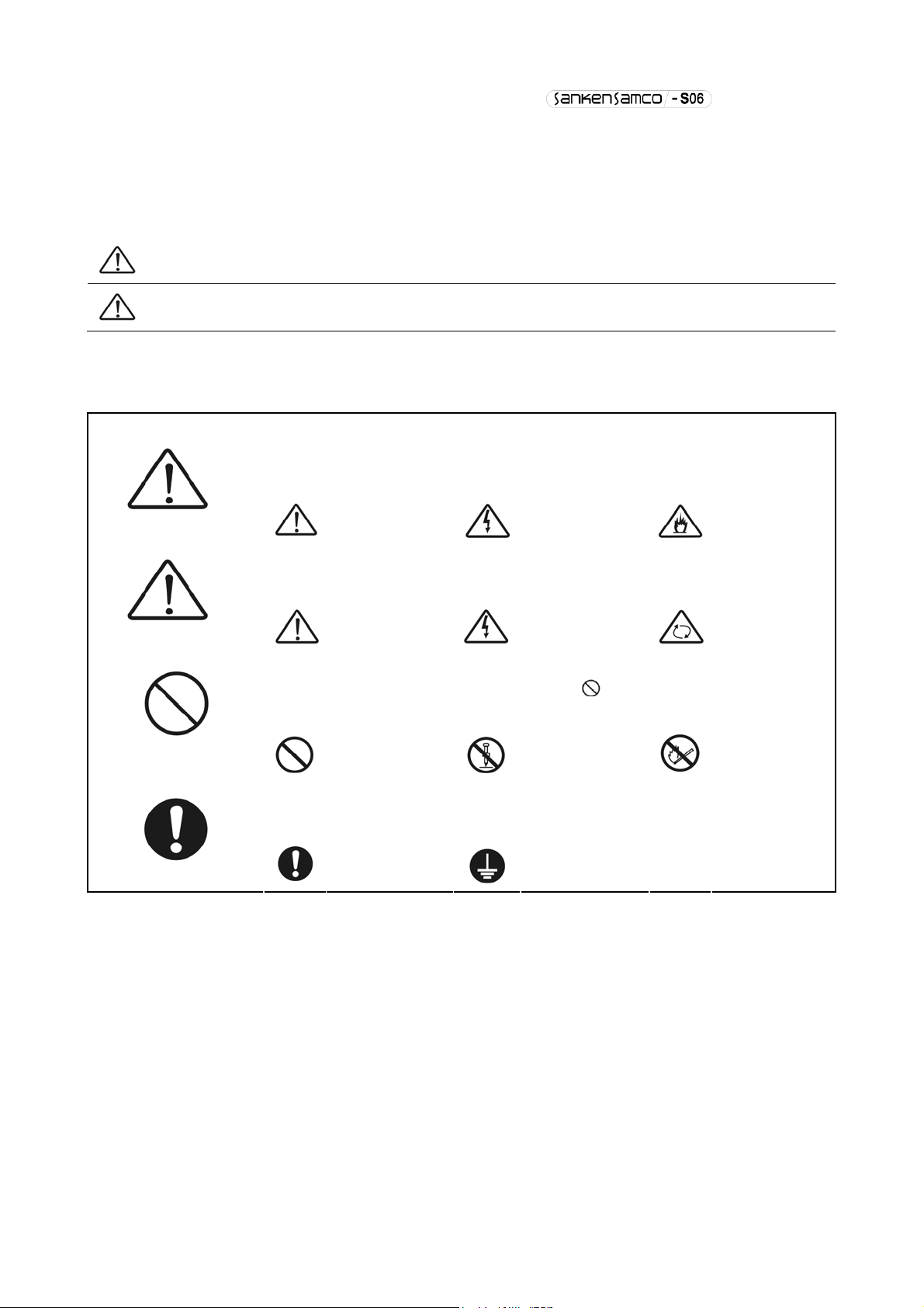
Meanings of graphic symbols
This symbol indicates a potential danger.
The specific content of danger is indicated within Ì. (this example indicates a general danger.)
This symbol indicates the need for caution.
The specific content of caution is indicated within Ì. (This example indicates a general caution.)
This symbol indicates a prohibition (strictly prohibited).
The specific content of prohibition is indicated within
prohibition)
Gengeral danger
Gengeral danger
General prohibition
Electric shock
danger
Caution: risk of
electric shock
. (This example indicates a general
Disassembly is
prohibited
Fire danger
Caution:risk of
rotating objects
The use of open
fire is prohibited.
This symbol indicates an action that must be performed (the project that must be performed).
The specific content is indicated within. (This example indicates a general compulsory item.)
General
compulsory item
Must be grounded
- 1 -

CONTENTS
1. Safety Notes ...................................................................................... - 5 -
1-1 Important notes .......................................................................... - 5 -
1-2 Notes on Use ............................................................................. - 5 -
1-3 Notes on Installation .................................................................... - 5 -
1-4 Notes on Handling and Moving ............................................................. - 6 -
1-5 Notes on Wiring .......................................................................... - 6 -
1-6 Notes on Operation ....................................................................... - 7 -
1-7 Notes on Maintenance and Inspection ...................................................... - 7 -
1-8 Disposal ................................................................................. - 7 -
1-9 Others ................................................................................... - 7 -
2. Product Validation and Precautions on Use................................................... - 8 -
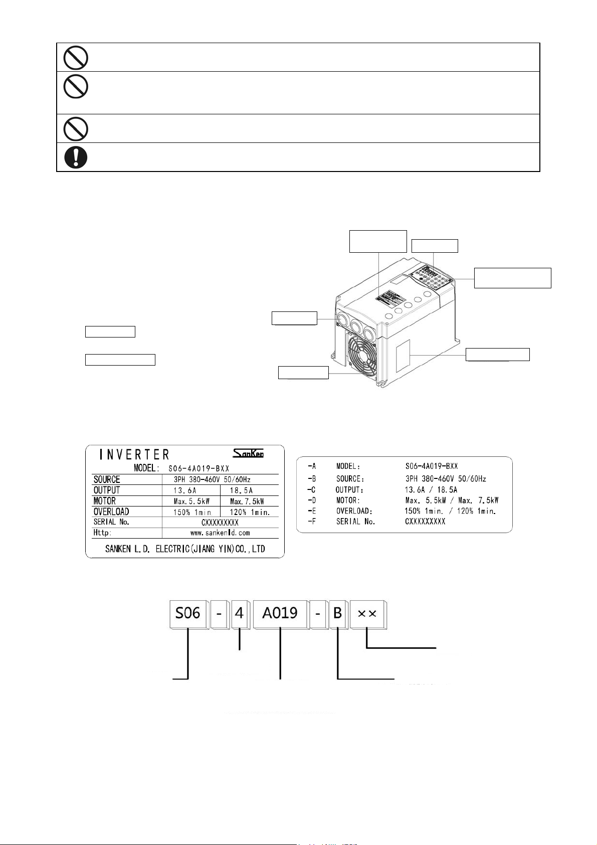
2-1 Product validation ....................................................................... - 8 -
2-2 Example of nameplate label ............................................................... - 8 -
2-3 The meanings of the model ................................................................ - 8 -
2-4 Precautions on Use ....................................................................... - 8 -
3. Installation............................................................................... - 10 -
3-1 Installation Location and Storage ....................................................... - 10 -
3-2 Installation Direction and Space ........................................................ - 10 -
3-3 Sketch of Front Cover Removal and Installation .......................................... - 11 -
4. Wiring..................................................................................... - 12 -
4-1 Connection with peripheral devices ...................................................... - 12 -
4-2 About Wiring ............................................................................ - 13 -
4-3 Terminal Wiring Diagram ................................................................. - 14 -
4-4 Composition of Main Circuit Terminals ................................................... - 15 -
4-4-1 Description of Main Circuit Terminals ............................................ - 15 -
4-4-2 Connection Diagram of Main Circuit Terminals ..................................... - 16 -
4-4-3 External brake resistor selection example ........................................ - 17 -
4-4-4 Capacities of MCCB and MC as well as Wire Size ................................... - 17 -
4-5 Composition of Control Circuit Terminals ................................................ - 18 -
4-5-1 Wire size and terminal arrangement ............................................... - 18 -
4-5-2 Schematic of control circuit terminal wiring ..................................... - 18 -
4-5-3 Functional list of control circuit terminals ..................................... - 18 -
4-5-4 Descriptions on control circuit terminal wiring .................................. - 20 -
4-6 Installation and Wiring of Optional Board ............................................... - 22 -
4-6-1 Overview of Optional Board ....................................................... - 22 -
4-6-2 Installation Method of Optional Board ............................................ - 22 -
5. Operation Panel............................................................................ - 23 -
5-1 Names and Functions of Parts of the Operation Panel ..................................... - 23 -
5-2 Description of keys on operation panel .................................................. - 24 -
5-3 Display mode of operation panel ......................................................... - 24 -
5-3-1 Version Display .................................................................. - 24 -
5-3-2 Inverter status mode ............................................................. - 25 -
5-3-3 Alarm display .................................................................... - 27 -
5-3-4 Frequency input .................................................................. - 27 -
5-4 Basic operation ......................................................................... - 28 -
5-4-1 Setting function code ............................................................ - 28 -
5-4-2 Confirming operation ............................................................. - 28 -
5-4-3 Signed operation ................................................................. - 29 -
5-5 Special functions ....................................................................... - 29 -
5-5-1 Copy function operation .......................................................... - 29 -
5-5-2 Changed code display operation ................................................... - 30 -
5-5-3 Function code initialization operation ........................................... - 30 -
5-5-4 Alarm contents reading operation ................................................. - 31 -
5-5-5 Alarm status confirmation operation .............................................. - 31 -
5-5-6 List of 7-segment monitor display ................................................ - 32 -
- 2 -

6. Operation.................................................................................. - 33 -
6-1 Operation steps ......................................................................... - 33 -
6-2 Test run ................................................................................ - 34 -
6-2-1 Confirmation before power input .................................................. - 34 -
6-2-2 Confirmation after power input ................................................... - 34 -
6-2-3 Basic setting (1) ................................................................ - 34 -
6-2-4 Motor control setting ............................................................ - 34 -
6-2-5 Basic setting (2) ................................................................ - 35 -
6-2-6 Motor parameter auto tuning ...................................................... - 35 -
6-2-7 Basic setting (3) ................................................................ - 38 -
6-3 Special functions ....................................................................... - 40 -
6-3-1 JOG operation .................................................................... - 40 -
6-3-2 Hold operation ................................................................... - 41 -
6-3-3 Notes on free run stop terminal (MBS) ............................................ - 41 -
7. Function Code .................................................................................... - 44 -
7-1 Representation and Description of Function Codes ........................................ - 44 -
7-2 Function Code List ...................................................................... - 44 -
7-3 Description of Functions ................................................................ - 62 -
7-3-1 Basic functions .................................................................. - 62 -
7-3-2 Input/Output-Related Functions ................................................... - 89 -
7-3-3 System functions ................................................................ - 100 -
7-3-4 Special functions ............................................................... - 109 -
7-3-5 Multi-speed Function ............................................................ - 115 -
7-3-6 PID Function .................................................................... - 128 -
7-3-7 Communication function .......................................................... - 143 -
7-3-8 Motor parameters ................................................................ - 145 -
7-3-9 Vector Speed Control ............................................................ - 147 -
7-3-10 Torque control .................................................................. - 155 -
7-3-11 Single-Inverter Multi-Pump Water Supply ......................................... - 161 -
7-4 Serial Communication Function .......................................................... - 164 -
7-4-1 Outline ......................................................................... - 164 -
7-4-2 Terminal functions and wiring methods ........................................... - 165 -
7-4-3 Operation and function code setting by serial communication ..................... - 165 -
7-4-4 Communication with dedicated protocol (SANKEN communication protocol) ........... - 167 -
7-4-5 Programming Design .............................................................. - 168 -
7-4-6 ModBus-RTU Communication ........................................................ - 181 -
8. Protection & Error Function............................................................... - 190 -
8-1 Operation error ........................................................................ - 190 -
8-2 Conflict & interference error .......................................................... - 190 -
8-3 Warning Status ......................................................................... - 194 -
8-4 Alarm Status ........................................................................... - 194 -
9. Fault Analysis............................................................................ - 198 -
10.Maintenance & Inspection ........................................................................ - 199 -
10-1 Precautions on Checking and Maintenance ................................................ - 199 -
10-2 Inspection Items ....................................................................... - 199 -
10-3 Part Replacement ....................................................................... - 200 -
10-4 Megger Test ............................................................................ - 200 -
10-5 Electrical measurement of main circuit ................................................. - 201 -
11.Specification Parameters ........................................................................ - 203 -
11-1 Standard specification ................................................................. - 203 -
11-2 Inverter general specification ......................................................... - 204 -
11-3 Communication function specification ................................................... - 205 -
11-4 Storage Environment .................................................................... - 205 -
12.Overall Dimension ............................................................................... - 206 -
12-1 Mainbody dimension ..................................................................... - 206 -
12-2 Operation panel ........................................................................ - 206 -
- 3 -

12-2 Operation panel ........................................................................ - 207 -
13.Peripheral Equipments & Options ................................................................. - 208 -
- 4 -
1. Safety Notes
1-1 Important notes
Caution: risk of electric shock
The disassembly of cover is absolutely probibited, otherwise the risk of electric shock and casualty may
exist.
Caution: Fire Hazard!
Immediately shut down the power supply and contact with the Seller when peculiar smell, abnormal noise,
smoke or sparks, etc. are found in the device.
In case of a fire, please use the extinguisher for electrical fire (dry powder), but do not use water for fire
fighting.
1-2 Notes on Use
Before starting the inverter, confirm the safety status of the load first, and then start running operation following
the instruction manual.
Failure to observe this may result in the danger of electric shock and other accidents.
Do not smoke or use fireworks around the inverter.
Failure to observe this may result in personalinjury and fire.
Do not keep containers which contain water above the equipment, such as vase, etc.
The water may infiltrate into the equipment interior and cause a fire.
Do not sit or stand on top of the equipment, and do not lean on it or treat it as a footboard.
Failure to observe this may overturn the equipment and result in personal injury.
Do not insert sticks, fingers etc. into the fan.
The rotating fan would cause personal injury.
During operation, do not short-circuit the input terminal and output terminal.
The current return will result in electric arc, which can cause personal burns and visual impairment.
Its use in the following applications is absolutely prohibited.
a) Medical equipment which are directly related to life.
b) Trolley buss which may lead to personal injury.
c) Important computer systems for the community and public utilities.
d) Equipment with these as standards.
Otherwise it may have significant impact on personal safety and the maintenance of public functions.
Please consult the Company in advance when it is used in the above-mentioned load equipment.
Danger
Caution
1-3 Notes on Installation
It is absolutely prohibited to store or use the inverter under the environmental conditions described below.
Failure to observe this warning may result in a fault, damage or deterioration, which could lead to fire.
y Very hot, cold, humid or outdoor locations, of which the environmental conditions are beyond that recorded
in the instruction manual.
y Locations which are in direct sunlight or near a heater or other heat sources.
y Locations subject to vibration or physical shock.
y Locations near machinery that generates sparks.
y Locations subject to dust, corrosive gas, salt, inflammable gas and water droplets.
y Locations higher than 3000 meters above sea level.
y Other similar environments.
Caution
- 5 -
Mount the inverter on a metal surface or other non-flammable surfaces.
Failure to observe this may result in a fire.
Install the inverter in a location that can bear its weight according to the instruction manual.
Failure to observe this may result in injuries as the inverter falls down.
Do not plug up the air inlet/exhaust.
Failure to observe this may result in a fire due to internal temperature rise of the equipment.
Do not place the inverter near flammable materials.
Failure to observe this may result in a fire.
Do not allow foreign objects into the inverter or attach to the cooling fans.
Failure to observe this may result in a fire or an accident.
Do not operate an inverter which is damanged, lacking parts or dented.
Failure to observe this may result in an electric shock, injury, fire or other accidents.
1-4 Notes on Handling and Moving
During handling and moving, do not tilt the equipment.
Failure to observe this may result in personal injury due to falling down of equipment.
Prior to handling and moving, confirm the weight marking attached to the equipment first; please prepare
alternative handling machine for work as necessary.
Failure to observe this may result in personal injury.
Caution
1-5 Notes on Wiring
Wiring must be performed by qualified personnel.
Improper wiring may result in electric shock or fire.
Do not connect AC power to an output terminal (U, V or W).
Failure to observe this may result in personal injury or fire.
Do not use if rated voltage is exceeded.
Failure to observe this may result in personal injury or fire.
Do not connect a resistor directly to the DC terminals (P and X).
Failure to observe this may result in a fire.
Connection between the ground terminals must be reliable.
Failure to observe this may result in an electric shock.
Please tighten the terminal block screws according to specified tightening torques.
Failure to observe this may result in a fire.
Check that the AC power voltage is consistent with the rated voltage of the inverter.
Failure to observe this may result in personal injury or fire.
For cable types and diameters, please use the cables specified in the instruction manual.
Failure to observe this may result in a fire due to wire heating.
Secure the inverter before wiring.
Failure to observe this may result in personal injury or fire.
Danger
Caution
The inverter, motor or wiring may cause interference. Please note misoperation of peripheral devices.
Failure to observe this may result in accidents.
If the input and output are terminal blocks, the wire heads must be connected with crimp terminals.
Failure to observe this may result in personal injury or fire.
- 6 -
1-6 Notes on Operation
Connect the input power only after attaching the front cover, and never remove the cover when the power is on.
Failure to observe this may result in an electric shock.
Do not touch any switch with wet hands.
Failure to observe this may result in an electric shock.
Do not touch any inverter terminal when the inverter is energized, even if the motor is not running.
Failure to observe this may result in an electric shock.
Do not get close to the motor when the restart function is enabled, as it will re-start suddenly after the alarm stops.
(Design the system to ensure personal safety at restart.)
Failure to observe this may result in personal injury.
Provide a separate emergency stop switch.
Failure to observe this may result in personal injury.
If the alarm is reset with the operation signal set, the equipment will restart suddenly. Therefore, please cut off the
operation signal before releasing an alarm.
Failure to observe this may result in personal injury.
Do not touch the radiator fins or DC reactor, beacause they become very hot.
Failure to observe this may result in burns.
It is easy to set the inverter drive speed from low to high, so be sure to confirm the allowable operating range of
the motor or machinery before the operation.
Failure to observe this may result in personal injury.
Please set separate brake if it is required to keep braking.
Failure to observe this may result in personal injury.
Do not start or stop the inverter by turning the main circuit ON or OFF.
Failure to observe this may result in equipment faults.
Danger
Caution
1-7 Notes on Maintenance and Inspection
Works such as maintenance, inspection and replacement of parts can only be carried out by professional
electricians.
[Take off any metal item (such as watch, bracelet, etc.) before working on the equipment.]
[Use insulated tools]
Failure to observe this may result in electric shock or burns.
Cut off the input power (OFF) for maintenance and inspection; only carry out the works with the voltage between
DC terminals P and X less than 30VDC after the [CHARGE] indicator lamp goes out.
Failure to observe this may result in electric shock and personal injury.
1-8 Disposal
When disposing this product, please entrust a specialized industrial waste disposal service.
If it is not handled by professionals, personal injury may be caused by capacitor explosion or the generated
harmful gas.
1-9 Others
Caution
Caution
Danger
- 7 -
Reformation of the product without authorization is strictly prohibited.
y
Failure to observe this may result in the risks of electric shock, personal injury, fault, damage or fire.
This product is designed for operation of a three-phase induction motor. Therefore it can not be used for
single-phase motor or other purposes.
Failure to observe this may result in a fire or an accident.
Do not use this product for life-support equipment, or other purposes directly related to dangers to human.
Failure to observe this may result in an accident.
Install a safety device when the failure of this product may cause a serious accident or damage.
Failure to observe this may result in an accident.
2. Product Validation and Precautions on Use
2-1 Product validation
After unpacking the product, please check the followings:
Check that the product has not been damaged during delivery,
such as depression of casing etc.
In case such problems are found, please contact the retailer.
S06 series product body (take S06-4A019-B** for example)
Wiring hole
Inverter body
As shown on right
Instruction Manual
this manual
2-2 Example of nameplate label
Cooling fan
Warning
identification
LED monitor
Multifunctional
numeric ke
Nameplate label
s
2-3 The meanings of the model
Series name
2-4 Precautions on Use
1. Use the product in a location satisfying the standard environmental specifications (temperature, humidity, vibration, dust,
water drop, toxic gases, etc.).
2. Before starting up the product for the first time, carefully check the wiring. Make sure that the power cable (input) and
Voltage class
4: 3-phase 400V
Rated current calibration
For example: A019 represents the motor
capacity corresponding to the rated
current of 18.5A is 7.5kW
- 8 -
Internal code
Overload mode
B stands for light overload which can
work for 1 minute @ 120%

motor cable (output) are connected correctly. Otherwise, the inverter will be damaged.
3. Since the service life of the inverter is greatly affected by the ambient temperature of the installation location, it is
recommended to lower the ambient temperature before operation.
4. When installing the product in a control cabinet, check the cabinet size and ensure sufficient ventilation.
5. When the capacitors and surge suppressors used for improving the power factor are connected to the inverter’s output
terminal, the inverter may be heated or even damaged bacause of the high-order harmonic components. Therefore, do not
connect the capacitors and surge suppressors to the output terminal of the inverter. To increase the power factor, you can
install the DC reactor at the DC side or install the AC reactor at the primary side (i.e. input terminal) of the inverter.
6. When implementing a megger test, follow the method given in this instruction manual (10-4 “Megger Test”).
7. When using leakage circuit breaker protection switch, select a product for corresponding high-order harmonic and surge.
8. In principle, there is no magnetic contactor between the inverter and the motor. However, if the magnetic contactor is
turned ON and OFF while the inverter is operating, an excess current will be generated.
9. Select larger capacity since the operating characteristics of full electromagnetic-type MCCB changes with high-order
harmonic current.
- 9 -
3. Installation
(op
)
b
3-1 Installation Location and Storage
Table 3-1 Work Environment Parameters
Ambient temperature
Storage temperature
Relative humidity Below 95%RH (without dewing)
Altitude Below 3000m (decrease the current when exceeding 1000m)
Vibration Below 5.9m/s2 (0.6G) (JIS C 60068-2-6 standard; IEC60068-2-6)
Gaseous media Indoor (free of corrosive gas, flammable gase, oil mist, dust, etc.)
Table 3-2 Storage Environment
Storage temperature
Relative humidity Below 95%RH (without frost)
Storage environment Places free of direct sunlight, corrosive or inflammable gases, oil mist, dust, steam, water droplet,
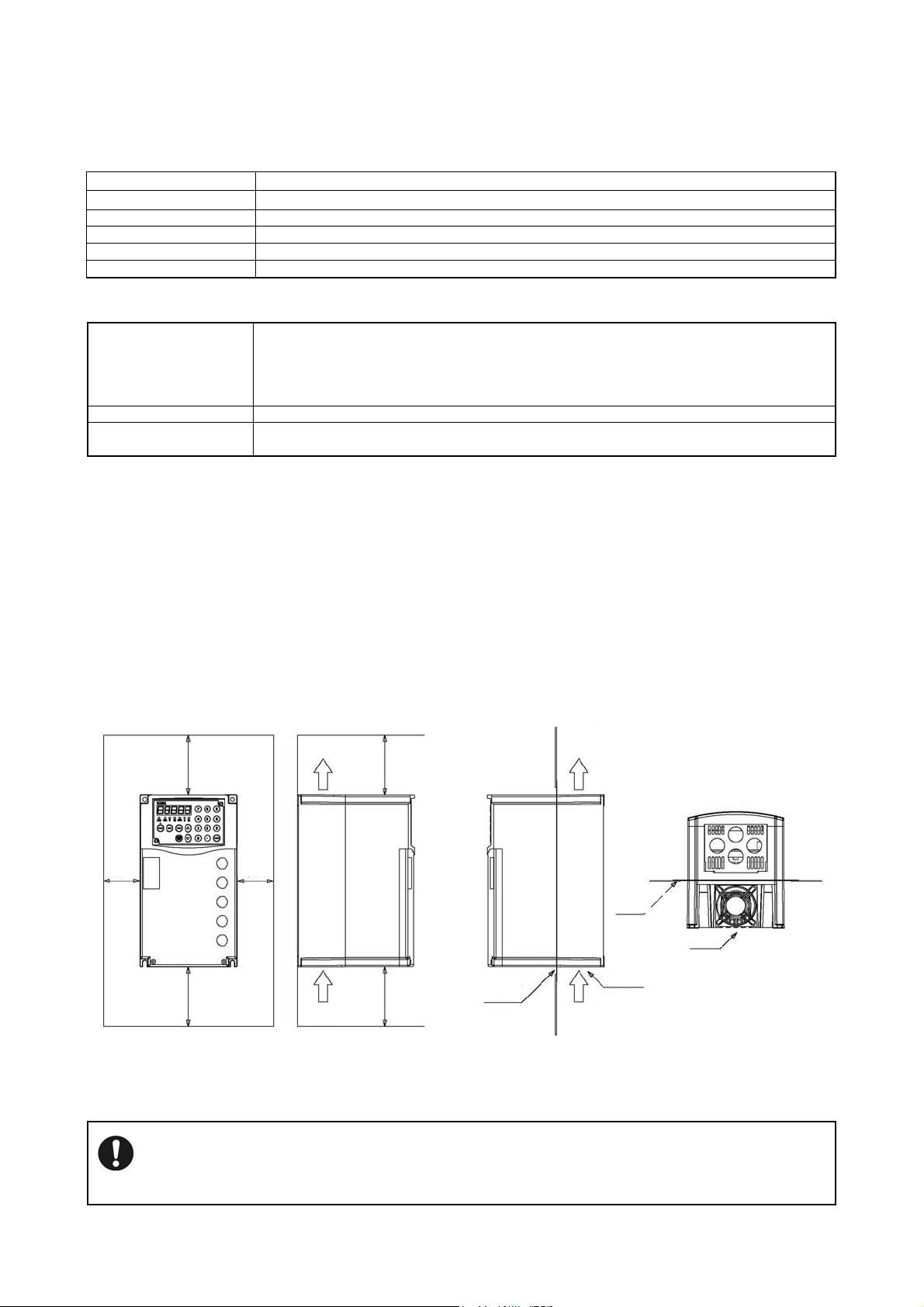
3-2 Installation Direction and Space
(1) This inverter is of the wall mounting type.
(2) Install the inverter vertically on a flat mounting surface.
-10℃~+50℃ (without freezing); heavy overload, -10℃~+40℃ (without freezing); light overload
-20℃~+65℃ (short-term preservation during transportation)
-20℃~+65℃
This temperature is for short periods, such as during transportation.
Ambient temperature must be 30°C or lower for more than 3 months of storage in consideration of
the deterioration of the electrolytic capacitor.
Furthermore, energize the equipment once per year when it is stored for more than one year.
vibration or high salinity.
(3) Since the inverter generates heat easily, provide adequate space around it to ensure good heat dissipation conditions.
(4) When installing the inverter in a control cabinet, provide a ventilation fan to keep the ambient temperature below 40°C.
(5) When installing the inverter in a control cabinet, mounting the radiator fins outside the control cabinet can help to reduce the
internal temperature of the cabinet.
(6) This inverter is of IP20 structure. Please select according to intended use.
Outside cabinet
Heating air
(optional)
Cooling fan
Cooling air
Mount
racket
Inside
cabinet
Outside
cabinet
Cooling fan
Above
5cm
Above 10cm
Above
Above 10cm
5cm
Heating air
Cooling air
Above 10cm
Above 10cm
Inside cabinet
Mount bracket
tional
Figure 3-1 Surrounding Space Figure 3-2 Arranging method of radiator fins
outside the cabinet
When several inverters are set in a control cabinet, be sure to locate the ventilation fans properly to allow free air
circulation.
Improper located ventilation fans will rise the ambient temperature, which will affect the cooling of the inverter.
- 10 -
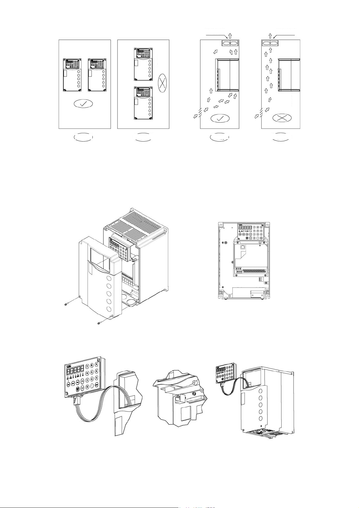
Ventilation fan
Overheat
Correct
Incorrect
Correct
Figure 3-3 Arranging method inside the cabinet Figure 3-4 Ventilation fan position in cabinet
3-3 Sketch of Front Cover Removal and Installation
(1) Removal of front cover (lower)
Unscrew the M4 screws, and pull the cover toward you while pressing both sides of the front cover (lower).
y Only carry out this work during the main circuit wiring, control circuit wiring and JP2 switching.
Ventilation fan
Overheat
Incorrect
(3) Removal of operation panel
Remove the operation panel and front panel during the installation, and re-install the front panel after the installation.
(2) Installation
When installing, work in reverse order.
- 11 -
4. Wiring
Read the Notes on Wiring (1-5) before wiring.
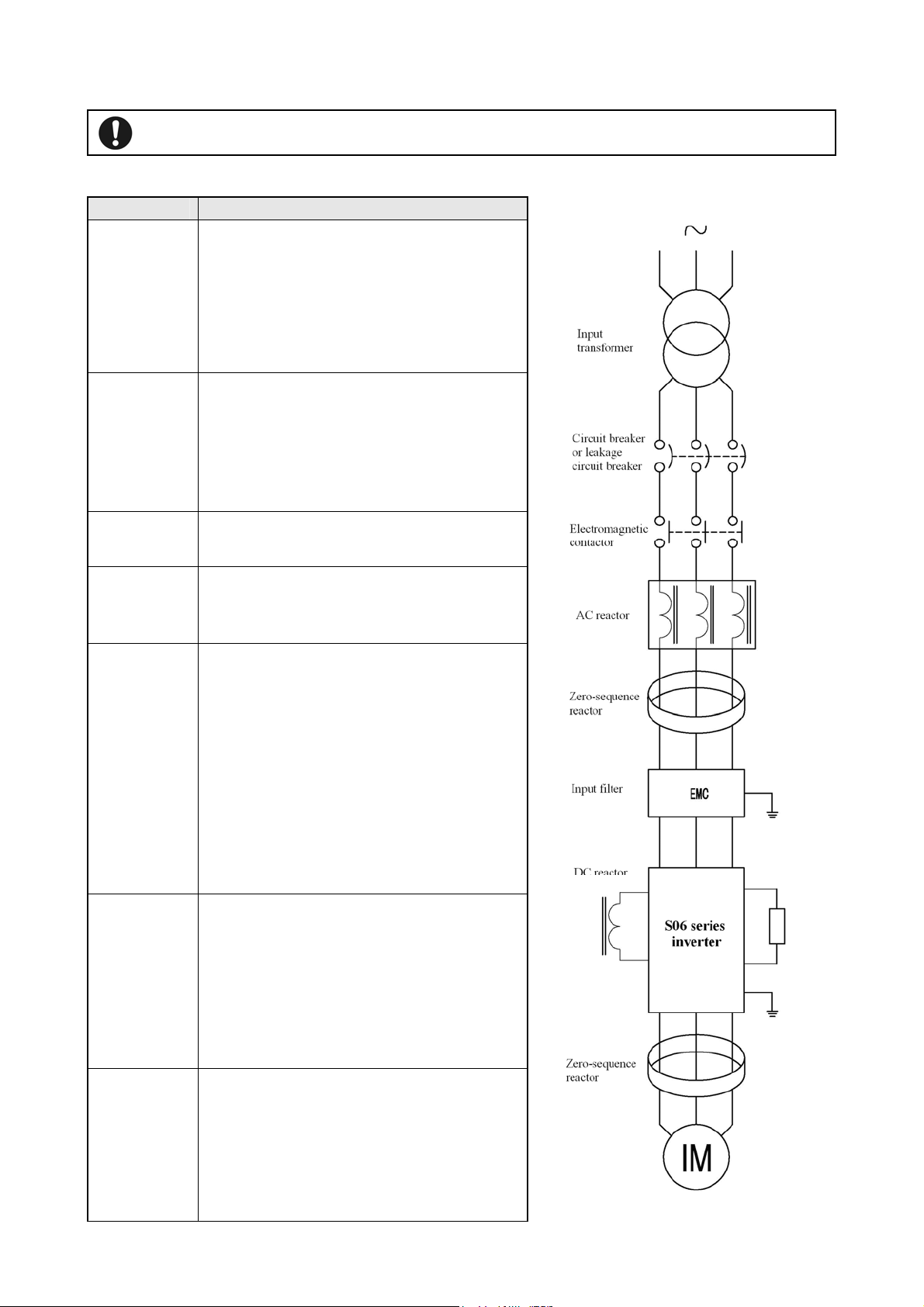
4-1 Connection with peripheral devices
Name Purposes and detailed description
Input power
supply
transformer
Circuit breaker
or leakage
circuit breaker
Failure to observe this may result in personal injury or fire.
When there is need for matching the system power
supply voltage with rated inverter input voltage, please
provide the input power supply transformer.
When several inverters are used, please provide the
input power supply transformer to reduce the impact of
high-order harmonic on other load devices.
Please connect wiring circuit breaker or leakage circuit
breaker in the overload protection circuit during
protection and wiring of the power supply system.
When using leakage circuit breaker, select a product for
corresponding high-order harmonic.
Electromagnetic
contactor
Surge absorber
AC reactor
DC reactor
Zero-sequence
reactor
Line noise filter
The coil must be provided with a surge absorber.
Please install the surge absorber for suppression of
surge generated on opening and closing of
electromagnetic contactors and control relays.
To achieve the following objectives, please install the
reactor
·Improve the inverter’s input power factor
·Reduce the impact on inverter due to unbalance
between phases of power supply voltage
·Prevent tripping of inverter due to action of phase lead
compensation capacitors in the system
·When the capacity of power supply is large (above
500kVA)
Reduce the interferences coming into input power
supply system of the inverter and generated by wiring.
It is recommended that elements such as zero-sequence
reactor etc. be inserted as close to inverter as possible.
Model name RC5078
Radio noise
filter
RC5096 [SOSHIN Electric Co., LTD]
Used to suppress the radio noise radiating to power
supply side of the inverter.
Model name 200V class: 3XYEB-105•104
400V class: 3XYHB-105•104
[OKAYA Electric Industries Co., LTD]
- 12 -
Reduce the interferences coming into input power
supply system of the inverter and generated by wiring.
Noise filter
It is recommended that noise filter be installed as close
to inverter as possible.
EMC filter recommended (please consult otherwise)
4-2 About Wiring
◆ Before carrying out wiring work, cut off the inverter’s input power supply, and make sure that no applied voltage
is present.
(1) Be sure to connnect a circuit breaker between the power supply and the input power supply terminals (R, S, T).
(Use a leakage circuit breaker specific to high-order harmonic when necessary.) To ensure the system safety,
connect a MC (electromagnetic contactor) between the circuit breaker and the input power supply.
(2) The phase order does not need to be considered when wiring the input power supply terminals (R, S and T).
(3) Connect the wires between the motor and the output terminals (U, V, W) correctly.
◆ The high-order harmonic leakage current increases accordingly when the total length of wiring between inverter
and motor is too long, which causes adverse affects on peripheral devices.
The total length of wiring between inverter and motor shall not exceed the values described in Table 4-1.
Table 4-1 Length of wiring between the inverter and the motor
Length of wiring between the inverter
and the motor
Carrier frequency
(Specified by F1009)
● When driving several motors at the same time, the total length of wiring to motors shall not exceed the values described
in Table 4-1. However, for vector control, the maximum wiring length shall be controlled within 100m. (For length of
more than 30m, please implement auto detecting mode 2)
● The surge voltage generated by the inverter element switching is superimposed and added to the motor terminal voltage.
The following measures should be considered to prevent deterioration of motor isolation especially for 400V class motors
when the length of wiring between the inverter and the motor is long.
① Use motors with reinforced isolation.
② Shorten the length of wiring between the inverter and the motor as possible (Generally about 10 - 20m).
(4) Refer to 4-5-4 for capacity of MCCB and MC as well as the wire sizes.
Use sleeved crimp terminals for the power and motor cables.
(5) Use shielded or twisted-pair wires for wiring to the control circuit terminals, while keep the wires well away
from the main and high-voltage circuits (including logic circuit of 200 V relay).
(6) Use a micro-signal contact or two-contact relay for the control circuit terminal to prevent poor contact.
(7) Ground the ground terminal ( ) securely.(Never use the casing or the chassis.)
According to technical standards for electrical equipment, 400V series shall be connected to the grounding
electrode for type C grounding.
Table 4-2 Types of grounding
Voltage Types of grounding Grounding resistance
400V series Type C grounding 10Ω or less
● Do not share the grounding wire with the welding machine or the power equipment.
● Use the grounding wire prescribed in the technical standards for electrical equipment, and shorten wiring length as much as
possible.
● Be careful not to loop the grounding wire when using multiple inverters.
50m 100m 200m
F1009=130 or less F1009=90 or less F1009=40 or less
- 13 -

(8) During wiring, please note that the inside of inverter shall be free from chips of wires.
◆ Control circuit wiring precautions
y Use shielded cable for analog input and output cables as well as the contact input cable (digital multifunctional input
terminals).
y To prevent misoperation due to interfenrence, the signal cables and power cables should be separated as possible during the
wiring (above 10cm).
y When using the operation panel for running, it can be realized only through the main circuit wiring (Without the need to
operate from the outside or by inputting frequency instructions).
y Connect the MCCB (circuit breaker) and other circuit protectors between the power supply and the input terminals.
y When the protective function of the inverter is enabled or the occurrence of other accidents, please connect the MC
(electromagnetic contactor) between MCCB and input terminals to cut off the inverter power supply, preventing further
expansion of failure or accident. Furthermore, the MC should be connected as close to the inverter as possible.
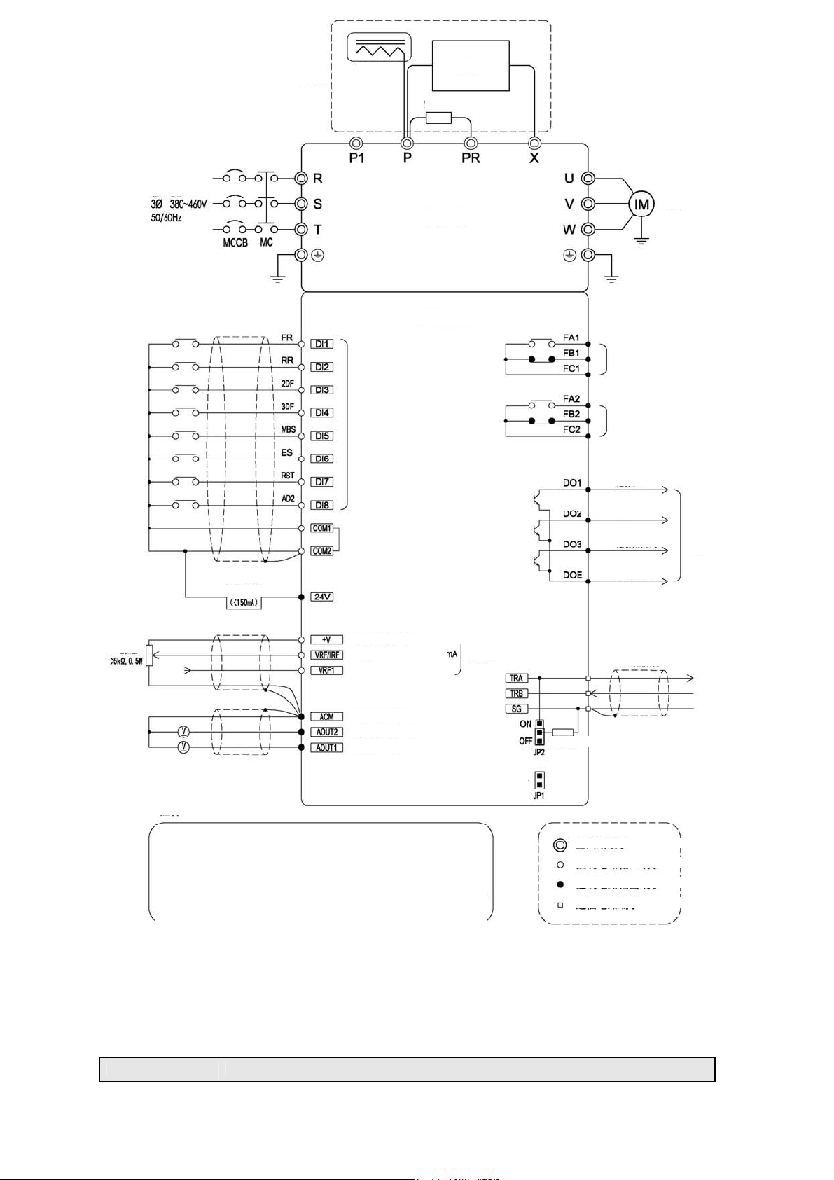
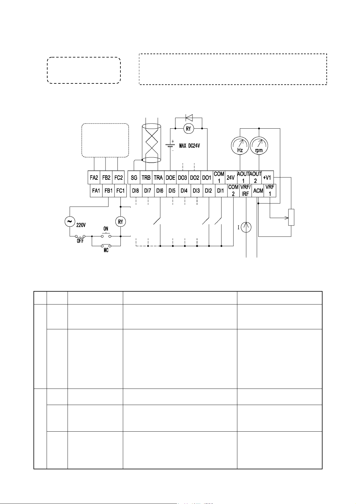
4-3 Terminal Wiring Diagram
- 14 -
Option
r
r
p
y
DC
reacto
Brake unit
Brake resisto
Input power
User load
Main circuit
Control circuit
Multifunctional input
terminal
Note: 5※
Digital signal
common ground
(internally
connected)
24V outside
ower output
Motor
Note: 1※
Multifunctional contact output 1
Contact capacity: 250V, 0.3A
Note: 2※
Multifunctional contact output 2
Contact capacity: 250V, 0.3A
Driving 1
Consistent
frequency
Overload prealarm
signal
Common
signal ground
Open collector
24V 50mA or less
Note: 3※
Potentiometer
Notes:
1: Ground ※ the inverter and motor reliably before use
2: Two groups ※ of separate multifunctional contact outputs, which can be selected and
set by F1513 & F1514
3: Multifunctional open collector output DO terminal, which can be selected and set b
F1509-F1511
4: Switch ※ the function with function code F1002. The terminal can be used as an input
terminal for various feedback signals
5: Multifunctional input terminal, can be assigned with different functions using ※
function code F1414 to F1421
6: This jumper terminal is used for version update, never use it under normal ※
circumstances
4-4 Composition of Main Circuit Terminals
Frequency setting power 12V
Frequency setting terminal
Frequency setting terminal
Analog signal common terminal 12G
Analog output DC0-10V
Analog output DC0-10V
Note: 4※
Update terminal
Note: 6※
※
RS485 communication terminal
Terminal resistor
Main circuit terminal
Control circuit input terminal
Control circuit output terminal
Communication circuit terminal
4-4-1 Description of Main Circuit Terminals
Terminal symbol Name Description
- 15 -
R,S,T Input power supply terminals Terminals connected to a three-phase commercial
r
r
r
power supply
U,V,W Inverter output terminals Terminals connected to a three-phase induction motor
P,P1 DC reactor connection terminals
P,PR Brake resistor connection terminals Terminals connected to a brake resistor between P-PR
P,X DC side voltage terminals
Ground terminal Terminal for grounding of inverter casing
Terminals connected to a DC reactor ※1
Terminals connected to a brake unit
P is the DC positive terminal, X the DC negative
terminal
※1 When connecting the DC reactor, please remove the jumper between P1 and P.
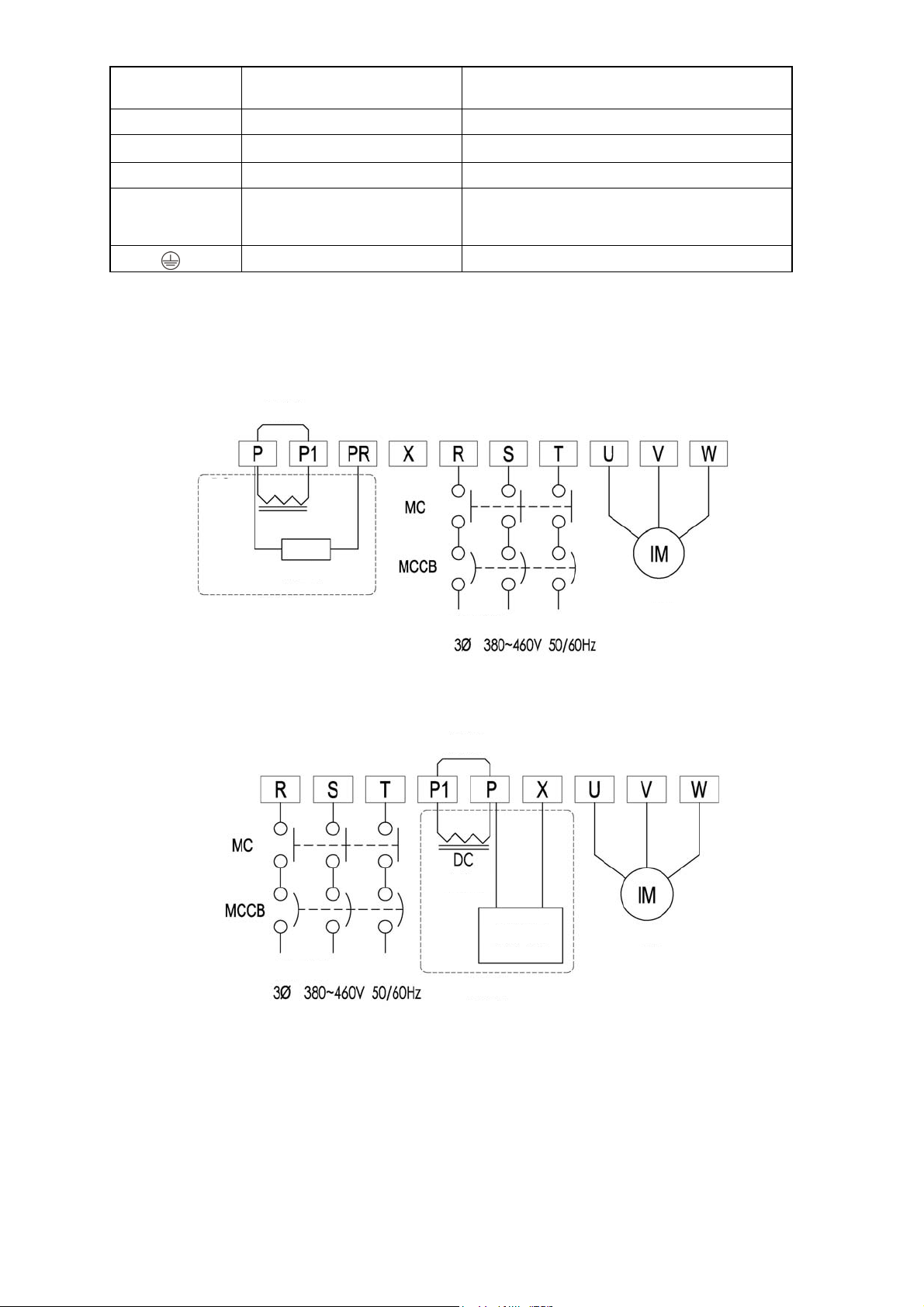
4-4-2 Connection Diagram of Main Circuit Terminals
(1) S06-4A005~4A076
Jumper
DC
reactor
(2) S06-4A092~4A152
Brake resistor
Motor
Option
Input powe
Jumpe
Reacto
Brake unit Motor
Input power
Option
- 16 -
4-4-3 External brake resistor selection example
)
)
)
)
)
)
)
)
)
)
)
)
)
)
)
)
)
)
)
)
)
)
)
)
)
)
)
)
Model
S06-4A005-B** 700Ω or more 100W 420Ω or more 300W
S06-4A006-B** 320Ω or more 200W 190Ω or more 300W
S06-4A009-B** 160Ω or more 400W 130Ω or more 500W
S06-4A014-B** 120Ω or more 600W 80Ω or more 800W
S06-4A019-B** 80Ω or more 800W 52Ω or more 1100W
S06-4A025-B** 60Ω or more 1000W 38Ω or more 1500W
S06-4A032-B** 40Ω or more 1500W 32Ω or more 1800W
S06-4A038-B** 40Ω or more 1500W 32Ω or more 1800W
S06-4A049-B** 40Ω or more 1500W 32Ω or more 1800W
S06-4A061-B** 40Ω or more 1500W 32Ω or more 1800W
S06-4A076-B** 20Ω or more 3000W 16Ω or more 3600W
※1 The above brake resistor is selected by assuming the maximum duty cycle to be 10% ED. When % ED needs to be set above
10%, brake resistor capacity should be increased proportionally.
Example) When setting 20 % ED, the capacity should be doubled that of 10%ED.
External brake resistor (recommended) External brake resistor (limit value)
Resistance
Capacity ※1
Resistance
Capacity ※1
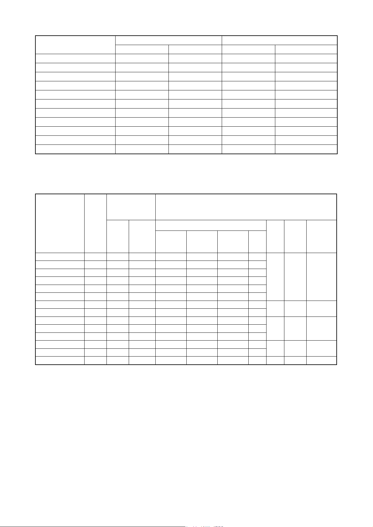
4-4-4 Capacities of MCCB and MC as well as Wire Size
Model MCCB
(Circuit
breaker)
[A]
(Electromagnetic
contactor)
Rated
current
[A]
MC
Rated
making
current
[A]
Recommended wire size [mm2]
Input wire P,P1 wires Output wire Ground
Main circuit
wire
Screw
diame
ter
Tighten
ing
Torque
[N•m]
Max. wire
size
[mm2]
S06-4A005-B** 5 7 20 2.0 (2.0
S06-4A006-B** 15 7 20 2.0 (2.0
S06-4A009-B** 20 7 20 2.0 (2.0
S06-4A014-B** 30 7 20 3.5 (2.0
S06-4A019-B** 30 17 32 5.5 (2.0
S06-4A025-B** 50 25 50 5.5 (2.0
S06-4A032-B** 60 25 50 8.0 (3.5
S06-4A038-B** 70 32 60 14 (5.5
S06-4A049-B** 75 48 80
S06-4A061-B** 100 65 100
S06-4A076-B** 125 75 135
S06-4A092-B** 150 75 135
S06-4A115-B** 175 150 200
S06-4A152-B** 225 150 200
Notes: The values for wires in the main circuit are for 600 V IV PVC-insulated wires (60ºC) when the inverter ambient
temperature is 40ºC. The values in parentheses are for 600 V bridged-polyethylene insulated wires (90ºC). The maximum
wire size indicates the maximum wire cross-sectional area that can be used with the terminal block.
14(5.5)
22(14)
38(14)
22×2(22)
60(38) 38(14) 22(14)
60(38) 60(22) 38(14)
2.0 (2.0
2.0 (2.0
2.0 (2.0
3.5 (2.0
5.5 (2.0
5.5 (2.0
8.0 (3.5
14 (5.5
22 (14
22 (14
22 (14
22 (14
2.0 (2.0
2.0 (2.0
2.0 (2.0
2.0 (2.0
3.5 (2.0
5.5 (2.0
8.0 (3.5
8.0 (3.5
8.0(5.5)
8.0(5.5)
14(5.5)
22(8)
M4 1.2 5.5
5.5
5.5
5.5
5.5
5.5
5.5
14
M5 2.0 14
14
14
M6 2.03 22
14
14
M6 4.52 60
22
22
22 M8 4.52 60
- 17 -
4-5 Composition of Control Circuit Terminals
d
4-5-1 Wire size and terminal arrangement
Terminal screw diameter:M3
Recommended wire size: 0.75[mm2]
Tightening torque:0.5[N•m]
※ The common end of control circuit terminals shall not be grounded to the earth.
※ COM1/COM2 shall not be in common use with ACM. (Because they are insulated with each other).
※ Do not input the voltage to multifunctional terminals (DI1-DI8).
4-5-2 Schematic of control circuit terminal wiring
RS485 communication
Other control
circuits composed
of relay 2-node
output
Surge suppressor
Single-phase
Emergency stop
4-5-3 Functional list of control circuit terminals
Ty
pe
Terminal
Symbol
COM
COM
DI1
DI2
DI3
DI4
DI5
DI6
①Multifunctional input
DI7
DI8
ACM
+V
②Analog input
VRF1
1
2
Terminal Name Function Description Rated Specification
Digital signal
common terminals
Digital
multifunctional input
Common terminals for digital input and output
signals and for +24V power supply
(1) The functions selected can be set through
function codes F1414~F1421.
terminals
Analog signal
common terminals
Analog input
potentiometer wiring
terminal
Common terminals for analog input and output
signals
Connected to a potentiometer of 5kΩ 0.3W or
above
z Carry out frequency setting through voltage
input
Analog voltage input
terminal
z Set the gain frequency corresponding to 5V
or 10V with voltage input.
z When “External analog forward / reverse
run” is selected, set the gain frequency
- 18 -
Reverse
Frequency
Forwar
RPM
display
display
Potentiometer
frequency setting
4-20mA input
Total current consumed:
100mA or less
Input resistor: about 6.6kΩ
When short-circuited: aboutDC3~
5mA
(1) Signal input “on” by
short-circuiting either COM1 or
COM2.
(2) Signal input “off” by opening
either COM1 or COM2.
Total current consumed: 100mA or
less
DC 10~12V
※It can not be connected to any
element other than the
potentiometer
Input resistor:
about 34kΩ
Maximum allowable voltage:
DC12V

corresponding to 10V (5+5V) or 0V (5-5V)
pp
y
p
with external analog value.
z The current/voltage in this channel can be
switched separately
z When frequency setting is selected, the
current/voltage input can be selected by the
Analog
current/voltage input
VRF
/IRF
l
24V Power supply output z Supply DC24V power to the user
su
③Power
terminals
(commonly used for
current/voltage input)
content of F1002.
z When carrying out frequency setting through
voltage input, set the gain frequency
corresponding to 5V or 10V with voltage
input.
z When “External analog forward / reverse
run” is selected, set the gain frequency
corresponding to 10V (5+5V) or 0V (5-5V)
with external analog value.
z When carrying out frequency setting through
current input, set the gain frequency
corresponding to 20mA.
For voltage input:
Input resistor: about 34kΩ
Maximum allowable voltage:
DC12V
For current input:
Input resistor: about 250Ω
Maximum allowable current: 30mA
Maximum allowable output current
for DC 24V: 150mA
Multifunctional
④Multifunctional
DOE
ut
DO1
out
DO2
DO3
AOU
AOU
⑤Analog output
TRA
TRB
⑥Communication terminal
FA1
FB1
FC1
FA2
FB2
FC2
⑦Contact output
output common
terminal
Multifunctional
output terminal
Analog output
T1
terminals
T2
RS485
communication
sending & receiving
terminals (+)
RS485
communication
sending & receiving
terminals (-)
RS485
communication
SG
common terminal
Abnormal alarm
signal output and
multifunctional
contact output
JP1 Upgrade jumper
z This terminal is DO1~DO3 shared
common terminal
z Open collector output
z Send signals through functions selected by
function codes
z Select the setting of signal output through
F1501~F1506
z Share the ground terminal with ACM analog
signal
z When connecting the computer using
RS485 communication interface, connect
the “+” signal terminal
z When connecting the computer using
RS485 communication interface, connect
the “-” signal terminal
z RS485 communication common terminal
z Connected to SG terminal on the
communication equipment
z These contact output terminals indicate that
the enabled protective function has stopped
the inverter.
z F1513, F1504: Select the setting for
multifunctional contact output according to
the relay 1 & 2 contact output
Used for short-circuiting during version upgrade
Allowable load: DC48V, 50mA
Signal output: DC 0~10V
Maximum output current: 15mA
Communication speed:
1200-57600bps
Total length: 500m
※When switch JP2 is located at
ON, connect the terminal resistor:
100Ω
※Choose the single terminal
grounding on inverter side or
communication equipment side
according to the site conditions
Contact capacity: AC250V/0.3A
When alarm contact is selected:
Normal: FA1,2-FC1,2 open
Abnormal: FA1,2-FC1,2 closed
※Do not connect anything to this
terminal except when upgrading.
Communication
JP2
⑧Jumper
terminal resistor ON
selector jumper
Choose whether to connect 100Ω terminal
resistor
- 19 -
OFF: terminal resistor is open
ON: terminal resistor is closed
4-5-4 Descriptions on control circuit terminal wiring
① Multifunctional input terminals
Digital multifunctional input terminals of DI1 - DI8 can be set to any one of the functions by using the function codes F1414 -
F1421 corresponding to various functions. In addition, a multiplexed terminal may have several functions.
When the function code is set to F1414=13, for example, the jog operation can be enabled simply by turning the DI1 terminal
on.
Table 4-4 List of multifunctional input codes
Function code No.
F1414 DI1
Input terminal
name
Data range Initial value (symbol)
1 (FR)
F1415 DI2 2 (RR)
F1416 DI3 3 (2DF)
F1417 DI4 4 (3DF)
F1418 DI5 5 (MBS)
0~255
F1419 DI6 6 (ES)
F1420 DI7 7 (RST)
F1421 DI8
8 (AD2)
※Refer to the description of selection functions of the input terminals DI1 - DI8 for details.
② Analog input terminals
1) Potentiometer for frequency setting
x The analog input has two channels: VRF1 voltage input and VRF/IRF voltage or current. They can be connected to the
potentiometer respectively, whose power supply terminal is +V common terminal and the ground terminal is ACM.
x Please install one 5kΩ potentiometer of 0.3W or above, and select the function code F1002: set the 1-speed frequency,
select the settings of current and voltage frequency.
x Use shielded cables for wiring, the control terminal shielding end should be connected to ACM shielded terminal, while
the other end will be left unconnected.
2) 4~20mA current for frequency setting
· Input the external 4~20mA control current through the VRF/IRF terminal and ACM, current direction: enter from
VRF/IRF and exit from ACM.
· By selecting function code F1002: set the 1-speed frequency, select the settings of current and voltage frequency.
③ 24V power terminal
· Provide the users with a DC24V power supply, which is used to connect encoders, transmitters or sensors, the
maximum load current should not exceed 150mA.
· Avoid overload or short circuit, otherwise it may result in damages.
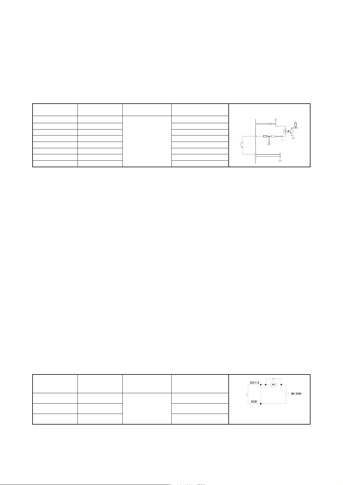
④ Multifunctional output terminal
· Digital multifunctional output terminals of DO1 - DO3 can be set to open collector output for any one of the functions by
using the function codes F1509 - F1511 corresponding to various functions.
x The multifunctional output terminal is the open collector output terminal, with a maximum voltage of 48V and a
maximum current of 50mA.
※ When using relays and other elements, be sure to install a surge suppressor (diode, reverse-parallel).
24V
DI1~
DI8
COM1
COM2
24V
COM
Table 4-5 List of multifunctional output codes
Function code No.
Input terminal
name
F1509 DO1
F1510 DO2
F1511 DO3
Data range
0~99
Initial value (function)
※
1(driving 1)
5(consistent frequency)
8(overload pre-alarm)
※Refer to the description of selection functions of DO1 - DO3 for details.
⑤ RS485 communication terminals
x The communication control with peripheral devices can be realized by using RS485 communication terminal block on the
- 20 -
following main control board.
x JP2 is a switch for turning ON / OFF the terminating resistor. Please set only the farthest terminating resistor switch of
the inverter to ON. (Factory preset= OFF: terminating resistor OPEN).
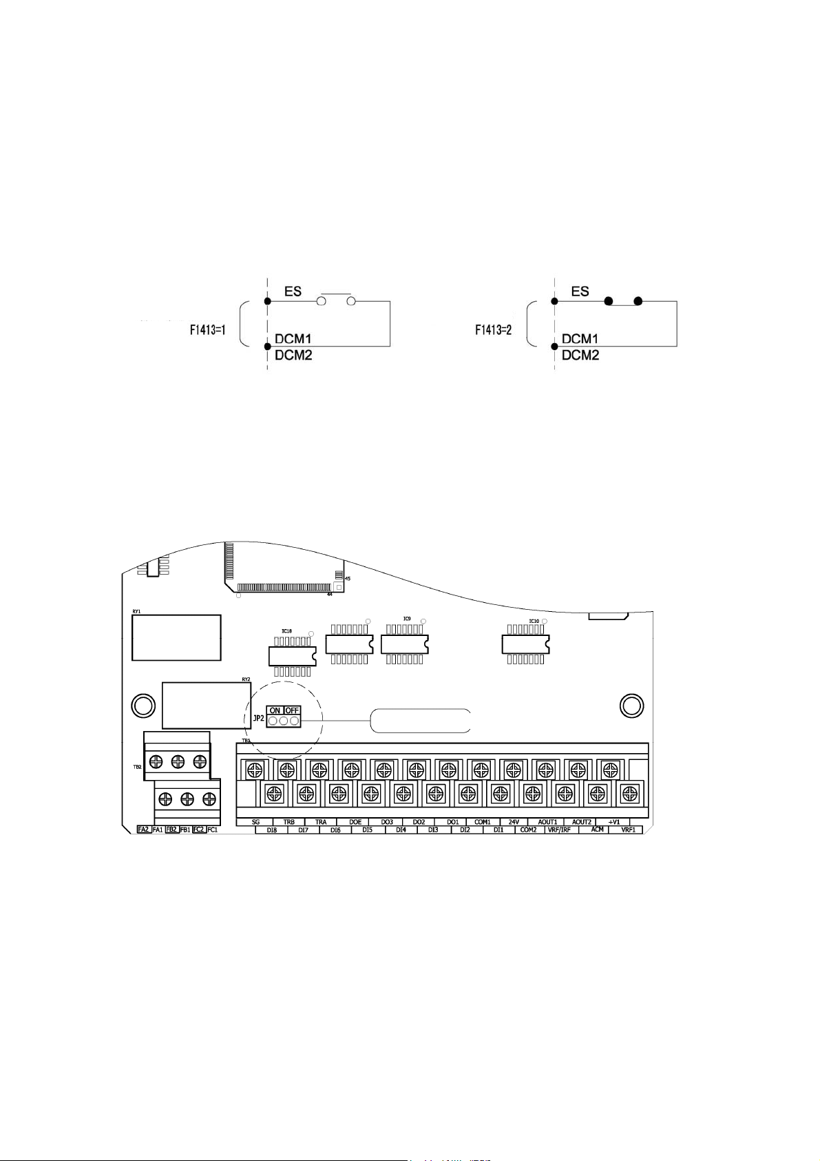
⑥ Contact output terminals
1) Signal mode switching for emergency stop (multifunctional input ES terminal)
x The figure below shows an example of signal switching when the multifunctional input terminal is set for the external
emergency stop (ES) command.
x A signal action is selected using the function code F1413: ES input terminal function.
When “normally open”
signal is input:
⑦ Jumper (JP2 communication terminal resistor ON selector jumper)
x When several inverters are communicating, place the JP2 of the farthest inverter into ON position, the terminal resistor
now will be connected, while its factory setting is OFF.
When “normally
closed” signal is
input:
Terminal resistor selector switch
- 21 -
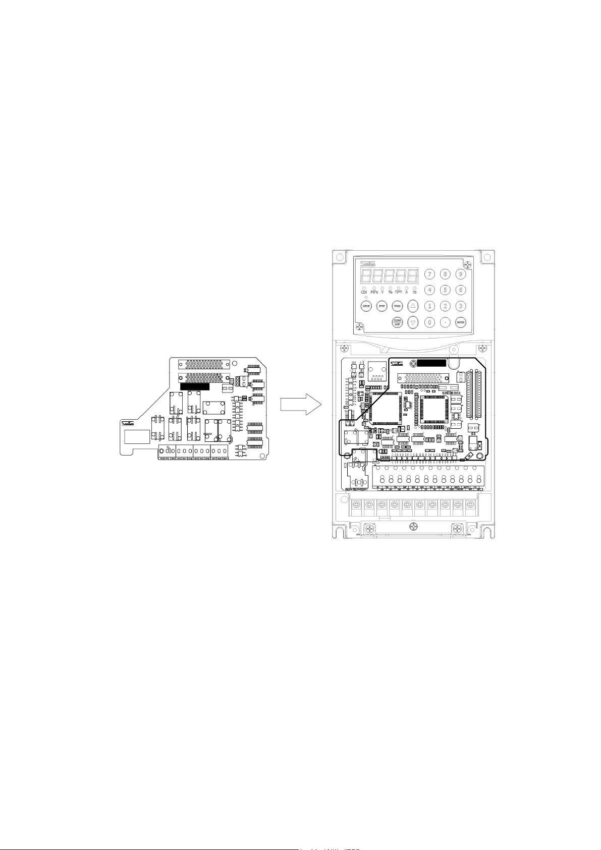
4-6 Installation and Wiring of Optional Board
4-6-1 Overview of Optional Board
Two optional boards can be installed on one inverter at the same time.
The shape of optional board may vary between different optional boards.
And sometimes, combination status of the optional board may also have impacts on installation and functions.
Refer to the instruction manual of each optional board for detailed functions of each optional board.
4-6-2 Installation Method of Optional Board
Remove the front cover before installing or removing an optional board.
When inserting an optional board into the slot, check if the connection between the mainframe side connector and the optional
board side connector is firm and reliable.
After the optional board has been installed, fix the optional board with attached screws (M3).
Shielded wires shall be used for wiring connected to terminals, with each common terminal connected to the shield.
Wiring shall be carried out according to the instruction manual of each optional board.
- 22 -
5. Operation Panel
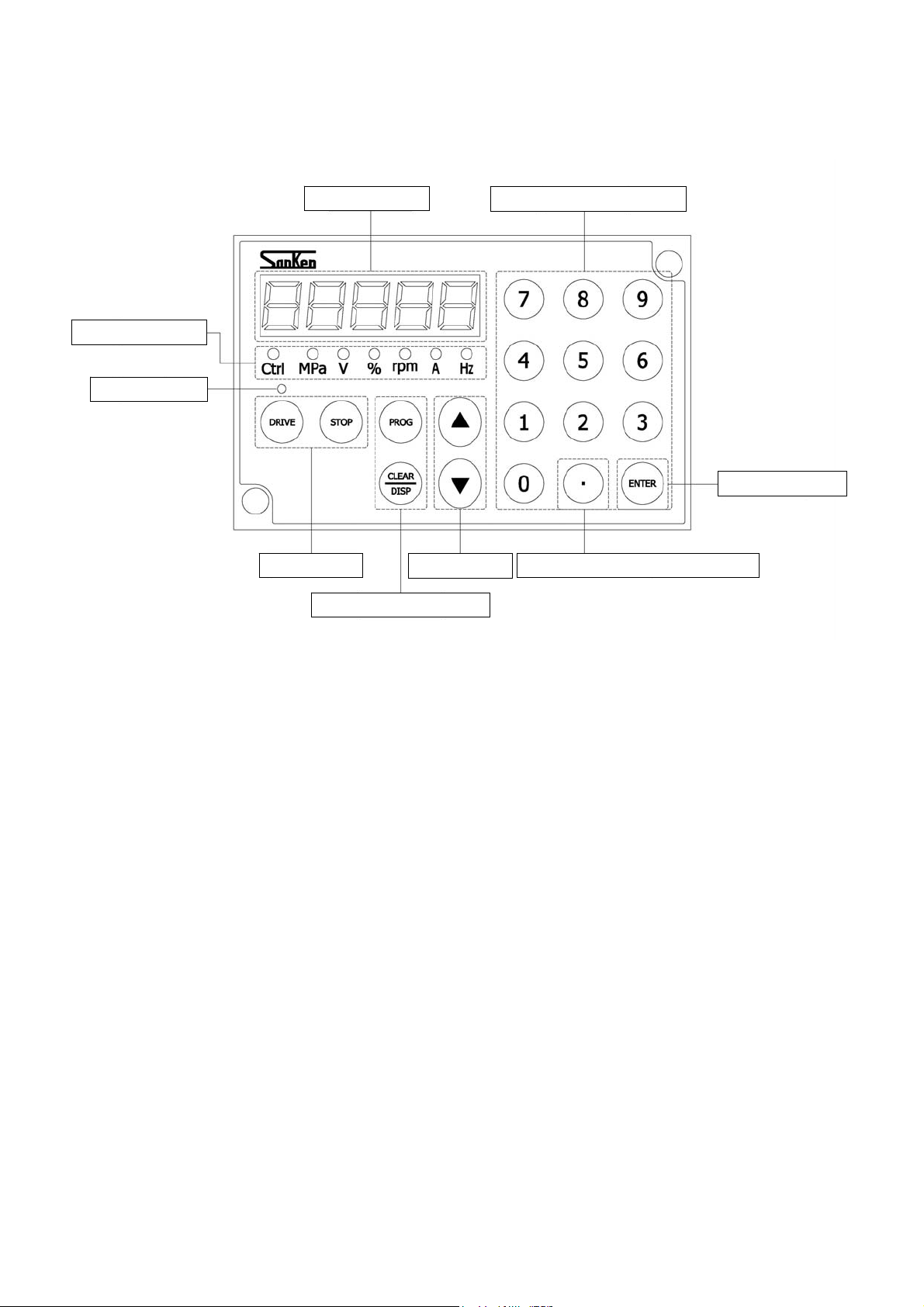
5-1 Names and Functions of Parts of the Operation Panel
LED status display
DRIVING display
For ease of operation, this series of inverters configure a numeric key panel as standard, to bring you the
following ease and convenience:
The numeric keypad with 0-9 decimal number input, even with the 0-F hexadecimal number input, can directly
While the 5-digit 7-segement LED tube, through the switching of DISP key, can clearly display the current
Using the light on/off/flashing statuses, the LED status indicator lamp can directly indicate the content and unit of
Furthermore, the in-control indicator (Ctrl) will display the status of external terminal driving/driving except
The DRIVING indicator lamp on the [DRIVE] button will turn on/off to indicate the DRIVE/STOP status, or will
The independent DRIVE/STOP key makes it easier to drive and stop the equipment.
The independent UP/DOWN key can also adjust the frequency or change the code through direct operations when
5-digit LED tube
Drive/Stop key
Combined programming key
input the parameter code, change the parameter settings, as well as set and modify the operation frequency very
easily.
operating frequency, input current, speed, load factor, output voltage, pressure, unit-free display value, setting
value and the alarm content.
7-segment LED tube, such as: frequency (Hz), output current (A), speed (Rpm), load factor (%), output voltage
(V) and the pressure (MPa).
external terminals.
flash to indicate STANDBY/DECELERATION/DC BRAKE and other status.
entering the numbers.
Up/Down key
Multifunctional numeric key
Enter/Confirm key
Decimal point hexadecimal switching
- 23 -
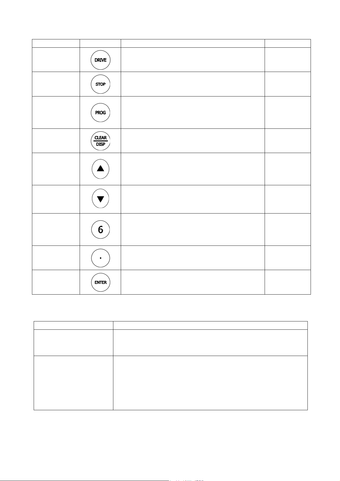
5-2 Description of keys on operation panel
Key Name Key Symbol Function Summary Shorted as
DRIVE key
STOP key
PROG key
CLEAR/
DISPLAY
switching
UP key
DOWN key
NUMBER key
(0-9)
DOT key
z Starts forward or reverse running operation.
z Stop operation
z Can be used for releasing alarm signal in alarm condition.
z In Status Display mode, change the Status Display mode to
Function Code Display mode
z In Function Code Display mode, return to the menu state of
previous page
z In Status Display mode, change contents displayed on the
7-segment monitor.
z In Function Code Display mode, clear the entered contents
z In Status Display mode, increase the frequency
z In Function Code Display mode, increase the code
z Can be used as “+” input for inputs with symbols
z Confirm some code setting
z In Status Display mode, decrease the frequence
z In Function Code Display mode, decrease the code
z Can be used as “-” input for inputs with symbols
z In Status Display mode, can be used to enter the frequency
directly
z In Function Code Display mode, can be used to enter the
code data directly
z Enter decimal point
z Combined with the numeric keys to enter the hexadecimal
codes of A-F
【DRIVE】
【STOP】
【PROG】
【CLEAR/DISP】
【UP】
【DOWN】
【0-9】
【DOT】
ENTER/CONFIRM
key
z Confirm the values displayed on 7-segment monitor which
will be entered into the host
【ENTER】
5-3 Display mode of operation panel
The operation panel 7-segment LED monitor has two display modes: [Status display mode] and [function code display mode],
and the modes can be switched by pressing the [PROG] key
Display mode Display contents
Status Display The inverter status during DRIVE and STOP
<Frequency> <Output Current> <Speed> <Load Factor> <Output Voltage>
<Pressure> <Uint-free Value>
Function Code Display Code number and data
Such as: Press [PROG] key to display F , enter “1202”
Display code F1202 (status display content selection)
Press [ENTER] to view the codes
Display 1 (Default display without unit)
Enter options via numeric key: such as “2” (output voltage)
After the setup is completed, the panel will display output voltage by default
The Status Display mode can carry out the inverter status monitoring, alarm display, output frequency setting as well as the
inverter DRIVE or STOP and other operations.
5-3-1 Version Display
Shortly after the power-on of the equipment, the software version of inverter will be displayed on 7-segment monitor. The
- 24 -
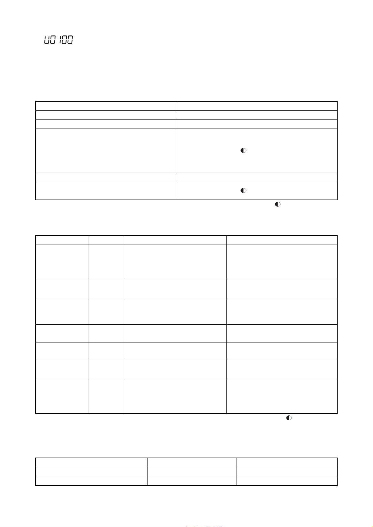
following is: display example for software version: VER 1.00.
If, for some reason, the host can not communicate with the operation panel when connected to the power, the 7-segment monitor
will display the software version of the operation panel. Now the monitor displays PXXXX.
5-3-2 Inverter status mode
The inverter status mode will be displayed.
In the operation mode display, various operation and stop states of the inverter are displayed.
Table 5-2 Display contents of operation mode
Operation Status Display Contents
Stopped z Running indicator
Driven { Running indicator
Deceleration to stop from forward run
Forward run waiting
Deceleration to stop from reverse run
Reverse run waiting
DC braking (reverse)
Frequency locking { Running indicator
Position control running
(Zero-servo running)
Monitor mode display refers to the contents displayed on the 7-segment monitor
Table 5-3 Display contents of monitor mode
Display Contents Unit Display Contents Display of 7-segment Monitor
Frequency Hz {Hz zA zrpm z% zV zMPa
Output current A zHz {A zrpm z% zV zMPa
Speed rpm zHz zA {rpm z% zV zMPa
Load factor % zHz zA zrpm {% zV zMPa
Output voltage V zHz zA zrpm z% {V zMPa
Pressure (option) MPa zHz zA zrpm z% zV {MPa
Status monitor
display
(No unit)
※1 Depending on the motor control modes, the display contents may be somewhat different. The display contents are as shown
in Table 5-4
Table 5-4 Display contents of speed
Motor control mode Running Stopped
Sensorless vector control Estimated speed of motor 0
Others Detecting speed of PG sensor Detecting speed of PG sensor
- zHz zA zrpm z% zV zMPa
Running indicator
Running indicator
{ Lit Flashing z Unlit
Running: the lit lamp indicates output
frequency
Stopped: the flashing lamp indicates setting
frequency
Running: the lit lamp indicates output current
Stopped: the flashing lamp indicates 0.0
Running: the lit lamp indicates speed (※1)
Stopped: the flashing lamp indicates speed
(※1)
Running: the lit lamp indicates load factor
Stopped: the flashing lamp indicates 0.0
Running: the lit lamp indicates output voltage
Stopped: the flashing lamp indicates 0.0
Running: the lit lamp indicates pressure
Stopped: the flashing lamp indicates 0.0
Running: the lit lamp indicates the values
selected by F1202
Stopped: the flashing lamp indicates the
values selected by F1202
{ Lit Flashing z Unlit
- 25 -

(V/f, vector etc.)
During the inverter’s status monitoring display, display contents of 7-segment monitor are shifted every time when the
[CLEAR/DISP] key is pressed. Display contents of 7-segment monitor can also be shifted through function codes. Refer to the
function code F1201 in [7-3 Description of Functions] for details.
※ Refer to the function code F1101 in [7-3 Description of Functions] for details of the operation command from an external
terminal / operation command from communication.
※ Sometimes this function is not available if set through the inverter’s function code.
- 26 -
5-3-3 Alarm display
When the alarm has stopped, the type of alarm will be displayed on the 7-segment monitor of the inverter. At this point, the
monitor mode displays that all the LEDs are flashing. See [8-4 Alarm Status] for the details of alarm display.
Display Contents Monitor mode display 7-segment Monitor Displays
Alarm display Hz A rpm % V MPa The type of an alarm is indicated by
the lamp
{ Lit
※ During alarm display, the display on 7-segment monitor can not be switched even by pressing [CLEAR/DISP] key.
※ During alarm display, pressing [PROG] key can switch current display to function code display mode.
Flashing z Unlit
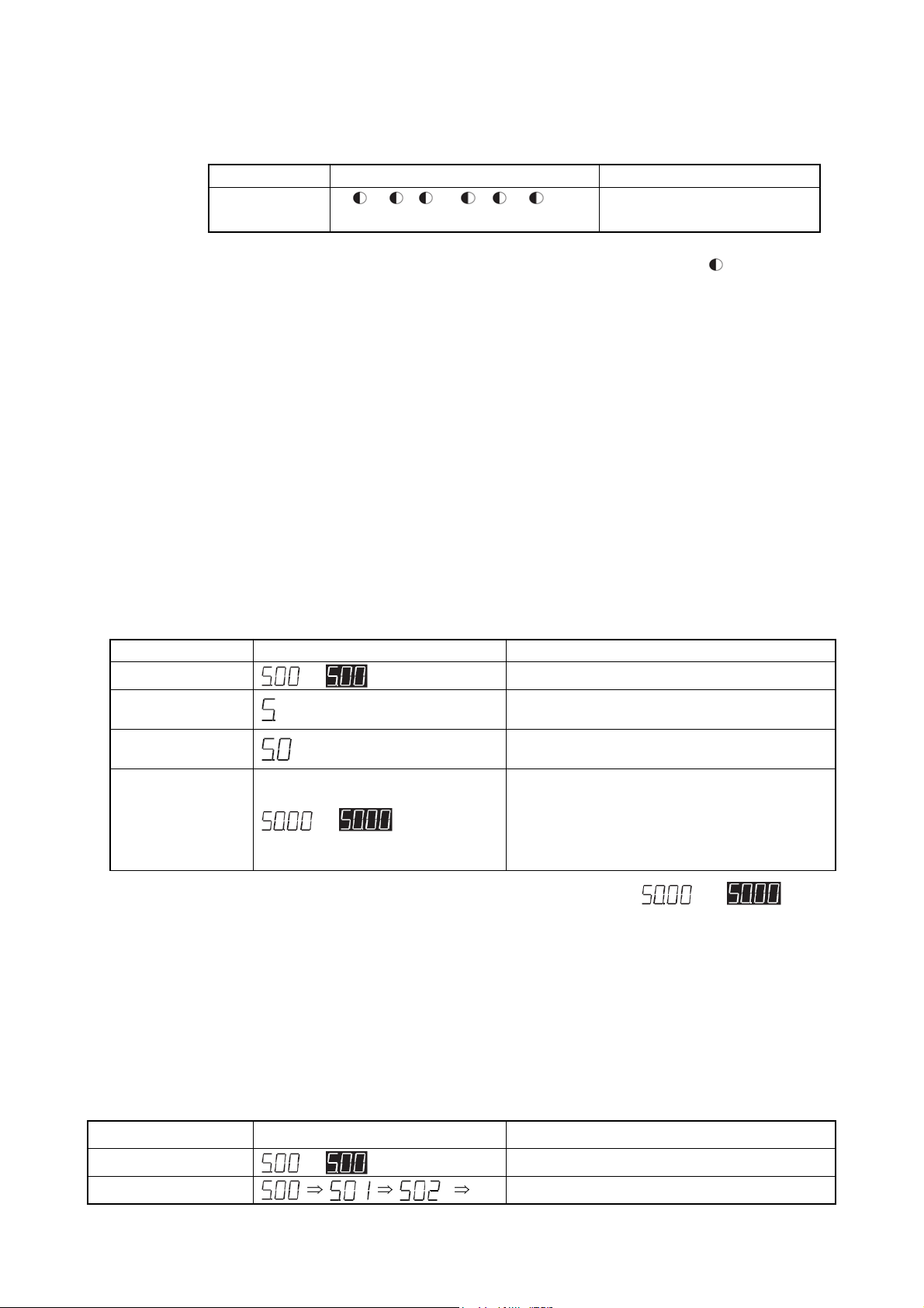
5-3-4 Frequency input
The frequency setting of the inverter can be input by using the numeric keys, [UP]/[DOWN] and [ENTER] keys, the following
are the two setting methods.
(1) Frequency setting A
Press the numeric keypad to modify the frequency to be set, then press [ENTER] key to confirm, this is the method of
frequency setting A.
x This is an effective method for setting a desired frequency.
x Cancellation can be made during frequency setting.
x In status monitor display, the method of frequency setting A can be used either in running or stopped state of the
equipment.
x This method can not be used during alarm display.
Operation example: changing from 5 Hz to 50 Hz
Operation Display Description
【5】
【0】
[ENTER] (press)
※1 If it is not necessary to set frequency, press [CLEAR/DISP] key to return to the status monitor display mode.
(2) Frequency setting B
Frequency setting B is a method for changing frequency by pressing [UP] / [DOWN] each time.
or
or
Display of status monitor (frequency display)
The value to be entered will be displayed on the
rightmost (※1)
The displayed data will move one digit to the left at
each time when the numeric key is pressed (※1)
Press this key, then the set value will be stored as a new
frequency value.
And the interface will return to status monitor display
mode. If this is done during running operation, then the
output frequency will start to change to the newly set
value.
Lit;
Flashing
x This is an effective method for fine-tuning of the set frequency during observation of the load conditions.
x In status monitor display, this method can be used either in running or stopped state of the equipment.
x This method can not be used during alarm display.
Operation example: changing the frequency from 5 Hz to 50 Hz
Operation Display
[UP] / [DOWN]
or
…
Display of status monitor (frequency display)
Press [UP] / [DOWN], and the value displayed will
Description
- 27 -

increase or decrease. The frequency changed will be
stored immediately as a new frequency value. If this is
done during running operation, then the output
frequency will start to change to the newly set value.
Lit;
The function code display mode can be used to set various functions of the inverter.
5-4 Basic operation
5-4-1 Setting function code
The basic operation is used for changing the value of a function code.
Operation example: setting F1414=10
Operation Display Description
[PROG]
Numeric key input
[1] [4] [0] [1]
Press [ENTER]
[UP]/[DOWN] or numeric
key[1] [0]
[ENTER]
[CLEAR/DISP]
[PROG]
※1 Use [UP]/[DOWN] can accurately index the values that can be set, ensuring that the input is valid, while you can not do this
using the numeric keys.
※2 If a new value is not required, the display can be returned back to the status monitor mode through the [PROG] key.
or
or
Display of status monitor (frequency display)
Press [PROG] key to display the function code input
interface
Enter the target function code, or use [UP] / [DOWN] to
adjust the current input
Press [ENTER] key to display the setting values of the
function code
Press [UP] / [DOWN], or press the numeric key to set the
target value (※1)
Press the [ENTER] or [PROG] key to confirm the new
setting, and the display screen will return to function code
selection.(※2)
Press [CLEAR/DISP] key to return the display screen to the
function code input interface
Press [PROG] key to return the display screen to status
monitor mode
Flashing
5-4-2 Confirming operation
For some function codes, operation needs to be re-confirmed to prevent data rewriting due to misoperation.
Operation example: setting F1001=10
Operation Display Description
[PROG]
Numeric key input
[1] [0] [0] [1]
[ENTER]
[UP]/[DOWN] or numeric
key[1] [0]
[ENTER]
[UP]
or
Display of status monitor (frequency display)
Press [PROG] key to display the function code input
interface
Enter the target function code, or use [UP] / [DOWN] to
adjust the current input
Press [ENTER] key, the monitor will display the setting
values of function code.
Modify the newly set value, the decimal point is invalid
Press [ENTER] key, the setting value and the
be display alternately, prompting the setting value is being
confirmed (※1)
Press [UP] again, the new setting will be confirmed and the
monitor will return to the function code selection interface
(※2)
will
- 28 -
[CLEAR/DISP]
[PROG]
※1 During alternate display period, if it is desired to interrupt input as any mistake in operation is found, press the
[CLEAR/DISP] key to return the display to the function code selection state.
※2 Press [PROG] key to return to the status monitor screen directly.
or
Press [CLEAR/DISP] key to return the display screen to the
function code input interface
Press [PROG] key to return the display screen to status
monitor mode
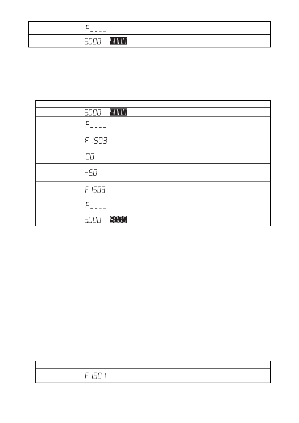
5-4-3 Signed operation
For some function codes, they can be set with values containing signs (polarity).
Operation example: setting F1503=-5.0
Operation Display Description
[PROG]
or
Display of status monitor (frequency display)
Press [PROG] key to display the function code input
interface
Numeric key input
[1] [5] [0] [3]
[ENTER]
Numeric key input
[5] [DOT] [0]
[DOWN]
[ENTER]
[CLEAR/DISP]
[PROG]
※ 1 Press [CLEAR/DISP] key to return back to the function code selection interface, the setting will be cleared without being
※ 2 Press [PROG] key to return to the status monitor mode directly.
saved.
or
Enter the target function code, or use [UP] / [DOWN] to
adjust the current input
Press [ENTER] or [PROG], the monitor will display the
setting values of function code.
Modify the newly set value, [DOWN] key is used for sign
switching
(※1)
Press the [ENTER] key to confirm the new setting, and the
display will return to function code selection interface. (※2)
Press [CLEAR/DISP] key, the monitor will return to the
function code input interface
Press the [PROG] key, and the monitor will return to status
monitor mode interface.
5-5 Special functions
5-5-1 Copy function operation
The so-called copy function is the function which transfers the function code data to other inverters after transferring the function
code data from one inverter side to the operation panel.
The copy function is an effective function where several inverters need to be set with the same function code data.
Only 1 inverter is set, while other inverters can also receive the same function code data, thus the same function code setting can
be easily implemented.
※ The copy function can be implemented only when the inverter stops working. Therefore, this operation shall be carried
out after the inverter has been stopped.
Operation example: copying from the inverter to the operation panel
Operation Display Description
Input or select function code F1610 (copy function)
- 29 -
 Loading...