

Sanken S06-4A025-B, S06-4A009-B, S06 Series, S06-4A006-B, S06-4A019-B Instruction Manual
...
High Performance Vector Control Multifunction Inverter
S06
Instruction Manual
Thank you for purchasing the Sanken High Performance Vector Control Inverter .
[For Safe Use]
Please read the instructions thoroughly and use it correctly before using this product.
After reading, please keep this manual near to the machines for convenient reference.
Expressions and meanings of safety notes
This symbol indicates a hazard that could lead to death or serious injury if the warning is ignored and the
product is handled incorrectly.
Danger
Caution
Furthermore, even an instruction marked [Caution] can also cause serious consequences under certain circumstances. Be sure to
abide by all instructions in this manual, irrespective of the degree of danger.
This symbol indicates a hazard that could lead to injury or damage to property if the warning is ignored and
the product is handled incorrectly.
Meanings of graphic symbols
This symbol indicates a potential danger.
The specific content of danger is indicated within Ì. (this example indicates a general danger.)
This symbol indicates the need for caution.
The specific content of caution is indicated within Ì. (This example indicates a general caution.)
This symbol indicates a prohibition (strictly prohibited).
The specific content of prohibition is indicated within
prohibition)
Gengeral danger
Gengeral danger
General prohibition
Electric shock
danger
Caution: risk of
electric shock
. (This example indicates a general
Disassembly is
prohibited
Fire danger
Caution:risk of
rotating objects
The use of open
fire is prohibited.
This symbol indicates an action that must be performed (the project that must be performed).
The specific content is indicated within. (This example indicates a general compulsory item.)
General
compulsory item
Must be grounded
- 1 -

CONTENTS
1. Safety Notes ...................................................................................... - 5 -
1-1 Important notes .......................................................................... - 5 -
1-2 Notes on Use ............................................................................. - 5 -
1-3 Notes on Installation .................................................................... - 5 -
1-4 Notes on Handling and Moving ............................................................. - 6 -
1-5 Notes on Wiring .......................................................................... - 6 -
1-6 Notes on Operation ....................................................................... - 7 -
1-7 Notes on Maintenance and Inspection ...................................................... - 7 -
1-8 Disposal ................................................................................. - 7 -
1-9 Others ................................................................................... - 7 -
2. Product Validation and Precautions on Use................................................... - 8 -
2-1 Product validation ....................................................................... - 8 -
2-2 Example of nameplate label ............................................................... - 8 -
2-3 The meanings of the model ................................................................ - 8 -
2-4 Precautions on Use ....................................................................... - 8 -
3. Installation............................................................................... - 10 -
3-1 Installation Location and Storage ....................................................... - 10 -
3-2 Installation Direction and Space ........................................................ - 10 -
3-3 Sketch of Front Cover Removal and Installation .......................................... - 11 -
4. Wiring..................................................................................... - 12 -
4-1 Connection with peripheral devices ...................................................... - 12 -
4-2 About Wiring ............................................................................ - 13 -
4-3 Terminal Wiring Diagram ................................................................. - 14 -
4-4 Composition of Main Circuit Terminals ................................................... - 15 -
4-4-1 Description of Main Circuit Terminals ............................................ - 15 -
4-4-2 Connection Diagram of Main Circuit Terminals ..................................... - 16 -
4-4-3 External brake resistor selection example ........................................ - 17 -
4-4-4 Capacities of MCCB and MC as well as Wire Size ................................... - 17 -
4-5 Composition of Control Circuit Terminals ................................................ - 18 -
4-5-1 Wire size and terminal arrangement ............................................... - 18 -
4-5-2 Schematic of control circuit terminal wiring ..................................... - 18 -
4-5-3 Functional list of control circuit terminals ..................................... - 18 -
4-5-4 Descriptions on control circuit terminal wiring .................................. - 20 -
4-6 Installation and Wiring of Optional Board ............................................... - 22 -
4-6-1 Overview of Optional Board ....................................................... - 22 -
4-6-2 Installation Method of Optional Board ............................................ - 22 -
5. Operation Panel............................................................................ - 23 -
5-1 Names and Functions of Parts of the Operation Panel ..................................... - 23 -
5-2 Description of keys on operation panel .................................................. - 24 -
5-3 Display mode of operation panel ......................................................... - 24 -
5-3-1 Version Display .................................................................. - 24 -
5-3-2 Inverter status mode ............................................................. - 25 -
5-3-3 Alarm display .................................................................... - 27 -
5-3-4 Frequency input .................................................................. - 27 -
5-4 Basic operation ......................................................................... - 28 -
5-4-1 Setting function code ............................................................ - 28 -
5-4-2 Confirming operation ............................................................. - 28 -
5-4-3 Signed operation ................................................................. - 29 -
5-5 Special functions ....................................................................... - 29 -
5-5-1 Copy function operation .......................................................... - 29 -
5-5-2 Changed code display operation ................................................... - 30 -
5-5-3 Function code initialization operation ........................................... - 30 -
5-5-4 Alarm contents reading operation ................................................. - 31 -
5-5-5 Alarm status confirmation operation .............................................. - 31 -
5-5-6 List of 7-segment monitor display ................................................ - 32 -
- 2 -

6. Operation.................................................................................. - 33 -
6-1 Operation steps ......................................................................... - 33 -
6-2 Test run ................................................................................ - 34 -
6-2-1 Confirmation before power input .................................................. - 34 -
6-2-2 Confirmation after power input ................................................... - 34 -
6-2-3 Basic setting (1) ................................................................ - 34 -
6-2-4 Motor control setting ............................................................ - 34 -
6-2-5 Basic setting (2) ................................................................ - 35 -
6-2-6 Motor parameter auto tuning ...................................................... - 35 -
6-2-7 Basic setting (3) ................................................................ - 38 -
6-3 Special functions ....................................................................... - 40 -
6-3-1 JOG operation .................................................................... - 40 -
6-3-2 Hold operation ................................................................... - 41 -
6-3-3 Notes on free run stop terminal (MBS) ............................................ - 41 -
7. Function Code .................................................................................... - 44 -
7-1 Representation and Description of Function Codes ........................................ - 44 -
7-2 Function Code List ...................................................................... - 44 -
7-3 Description of Functions ................................................................ - 62 -
7-3-1 Basic functions .................................................................. - 62 -
7-3-2 Input/Output-Related Functions ................................................... - 89 -
7-3-3 System functions ................................................................ - 100 -
7-3-4 Special functions ............................................................... - 109 -
7-3-5 Multi-speed Function ............................................................ - 115 -
7-3-6 PID Function .................................................................... - 128 -
7-3-7 Communication function .......................................................... - 143 -
7-3-8 Motor parameters ................................................................ - 145 -
7-3-9 Vector Speed Control ............................................................ - 147 -
7-3-10 Torque control .................................................................. - 155 -
7-3-11 Single-Inverter Multi-Pump Water Supply ......................................... - 161 -
7-4 Serial Communication Function .......................................................... - 164 -
7-4-1 Outline ......................................................................... - 164 -
7-4-2 Terminal functions and wiring methods ........................................... - 165 -
7-4-3 Operation and function code setting by serial communication ..................... - 165 -
7-4-4 Communication with dedicated protocol (SANKEN communication protocol) ........... - 167 -
7-4-5 Programming Design .............................................................. - 168 -
7-4-6 ModBus-RTU Communication ........................................................ - 181 -
8. Protection & Error Function............................................................... - 190 -
8-1 Operation error ........................................................................ - 190 -
8-2 Conflict & interference error .......................................................... - 190 -
8-3 Warning Status ......................................................................... - 194 -
8-4 Alarm Status ........................................................................... - 194 -
9. Fault Analysis............................................................................ - 198 -
10.Maintenance & Inspection ........................................................................ - 199 -
10-1 Precautions on Checking and Maintenance ................................................ - 199 -
10-2 Inspection Items ....................................................................... - 199 -
10-3 Part Replacement ....................................................................... - 200 -
10-4 Megger Test ............................................................................ - 200 -
10-5 Electrical measurement of main circuit ................................................. - 201 -
11.Specification Parameters ........................................................................ - 203 -
11-1 Standard specification ................................................................. - 203 -
11-2 Inverter general specification ......................................................... - 204 -
11-3 Communication function specification ................................................... - 205 -
11-4 Storage Environment .................................................................... - 205 -
12.Overall Dimension ............................................................................... - 206 -
12-1 Mainbody dimension ..................................................................... - 206 -
12-2 Operation panel ........................................................................ - 206 -
- 3 -

12-2 Operation panel ........................................................................ - 207 -
13.Peripheral Equipments & Options ................................................................. - 208 -
- 4 -
1. Safety Notes
1-1 Important notes
Caution: risk of electric shock
The disassembly of cover is absolutely probibited, otherwise the risk of electric shock and casualty may
exist.
Caution: Fire Hazard!
Immediately shut down the power supply and contact with the Seller when peculiar smell, abnormal noise,
smoke or sparks, etc. are found in the device.
In case of a fire, please use the extinguisher for electrical fire (dry powder), but do not use water for fire
fighting.
1-2 Notes on Use
Before starting the inverter, confirm the safety status of the load first, and then start running operation following
the instruction manual.
Failure to observe this may result in the danger of electric shock and other accidents.
Do not smoke or use fireworks around the inverter.
Failure to observe this may result in personalinjury and fire.
Do not keep containers which contain water above the equipment, such as vase, etc.
The water may infiltrate into the equipment interior and cause a fire.
Do not sit or stand on top of the equipment, and do not lean on it or treat it as a footboard.
Failure to observe this may overturn the equipment and result in personal injury.
Do not insert sticks, fingers etc. into the fan.
The rotating fan would cause personal injury.
During operation, do not short-circuit the input terminal and output terminal.
The current return will result in electric arc, which can cause personal burns and visual impairment.
Its use in the following applications is absolutely prohibited.
a) Medical equipment which are directly related to life.
b) Trolley buss which may lead to personal injury.
c) Important computer systems for the community and public utilities.
d) Equipment with these as standards.
Otherwise it may have significant impact on personal safety and the maintenance of public functions.
Please consult the Company in advance when it is used in the above-mentioned load equipment.
Danger
Caution
1-3 Notes on Installation
It is absolutely prohibited to store or use the inverter under the environmental conditions described below.
Failure to observe this warning may result in a fault, damage or deterioration, which could lead to fire.
y Very hot, cold, humid or outdoor locations, of which the environmental conditions are beyond that recorded
in the instruction manual.
y Locations which are in direct sunlight or near a heater or other heat sources.
y Locations subject to vibration or physical shock.
y Locations near machinery that generates sparks.
y Locations subject to dust, corrosive gas, salt, inflammable gas and water droplets.
y Locations higher than 3000 meters above sea level.
y Other similar environments.
Caution
- 5 -
Mount the inverter on a metal surface or other non-flammable surfaces.
Failure to observe this may result in a fire.
Install the inverter in a location that can bear its weight according to the instruction manual.
Failure to observe this may result in injuries as the inverter falls down.
Do not plug up the air inlet/exhaust.
Failure to observe this may result in a fire due to internal temperature rise of the equipment.
Do not place the inverter near flammable materials.
Failure to observe this may result in a fire.
Do not allow foreign objects into the inverter or attach to the cooling fans.
Failure to observe this may result in a fire or an accident.
Do not operate an inverter which is damanged, lacking parts or dented.
Failure to observe this may result in an electric shock, injury, fire or other accidents.
1-4 Notes on Handling and Moving
During handling and moving, do not tilt the equipment.
Failure to observe this may result in personal injury due to falling down of equipment.
Prior to handling and moving, confirm the weight marking attached to the equipment first; please prepare
alternative handling machine for work as necessary.
Failure to observe this may result in personal injury.
Caution
1-5 Notes on Wiring
Wiring must be performed by qualified personnel.
Improper wiring may result in electric shock or fire.
Do not connect AC power to an output terminal (U, V or W).
Failure to observe this may result in personal injury or fire.
Do not use if rated voltage is exceeded.
Failure to observe this may result in personal injury or fire.
Do not connect a resistor directly to the DC terminals (P and X).
Failure to observe this may result in a fire.
Connection between the ground terminals must be reliable.
Failure to observe this may result in an electric shock.
Please tighten the terminal block screws according to specified tightening torques.
Failure to observe this may result in a fire.
Check that the AC power voltage is consistent with the rated voltage of the inverter.
Failure to observe this may result in personal injury or fire.
For cable types and diameters, please use the cables specified in the instruction manual.
Failure to observe this may result in a fire due to wire heating.
Secure the inverter before wiring.
Failure to observe this may result in personal injury or fire.
Danger
Caution
The inverter, motor or wiring may cause interference. Please note misoperation of peripheral devices.
Failure to observe this may result in accidents.
If the input and output are terminal blocks, the wire heads must be connected with crimp terminals.
Failure to observe this may result in personal injury or fire.
- 6 -
1-6 Notes on Operation
Connect the input power only after attaching the front cover, and never remove the cover when the power is on.
Failure to observe this may result in an electric shock.
Do not touch any switch with wet hands.
Failure to observe this may result in an electric shock.
Do not touch any inverter terminal when the inverter is energized, even if the motor is not running.
Failure to observe this may result in an electric shock.
Do not get close to the motor when the restart function is enabled, as it will re-start suddenly after the alarm stops.
(Design the system to ensure personal safety at restart.)
Failure to observe this may result in personal injury.
Provide a separate emergency stop switch.
Failure to observe this may result in personal injury.
If the alarm is reset with the operation signal set, the equipment will restart suddenly. Therefore, please cut off the
operation signal before releasing an alarm.
Failure to observe this may result in personal injury.
Do not touch the radiator fins or DC reactor, beacause they become very hot.
Failure to observe this may result in burns.
It is easy to set the inverter drive speed from low to high, so be sure to confirm the allowable operating range of
the motor or machinery before the operation.
Failure to observe this may result in personal injury.
Please set separate brake if it is required to keep braking.
Failure to observe this may result in personal injury.
Do not start or stop the inverter by turning the main circuit ON or OFF.
Failure to observe this may result in equipment faults.
Danger
Caution
1-7 Notes on Maintenance and Inspection
Works such as maintenance, inspection and replacement of parts can only be carried out by professional
electricians.
[Take off any metal item (such as watch, bracelet, etc.) before working on the equipment.]
[Use insulated tools]
Failure to observe this may result in electric shock or burns.
Cut off the input power (OFF) for maintenance and inspection; only carry out the works with the voltage between
DC terminals P and X less than 30VDC after the [CHARGE] indicator lamp goes out.
Failure to observe this may result in electric shock and personal injury.
1-8 Disposal
When disposing this product, please entrust a specialized industrial waste disposal service.
If it is not handled by professionals, personal injury may be caused by capacitor explosion or the generated
harmful gas.
1-9 Others
Caution
Caution
Danger
- 7 -
Reformation of the product without authorization is strictly prohibited.
y
Failure to observe this may result in the risks of electric shock, personal injury, fault, damage or fire.
This product is designed for operation of a three-phase induction motor. Therefore it can not be used for
single-phase motor or other purposes.
Failure to observe this may result in a fire or an accident.
Do not use this product for life-support equipment, or other purposes directly related to dangers to human.
Failure to observe this may result in an accident.
Install a safety device when the failure of this product may cause a serious accident or damage.
Failure to observe this may result in an accident.
2. Product Validation and Precautions on Use
2-1 Product validation
After unpacking the product, please check the followings:
Check that the product has not been damaged during delivery,
such as depression of casing etc.
In case such problems are found, please contact the retailer.
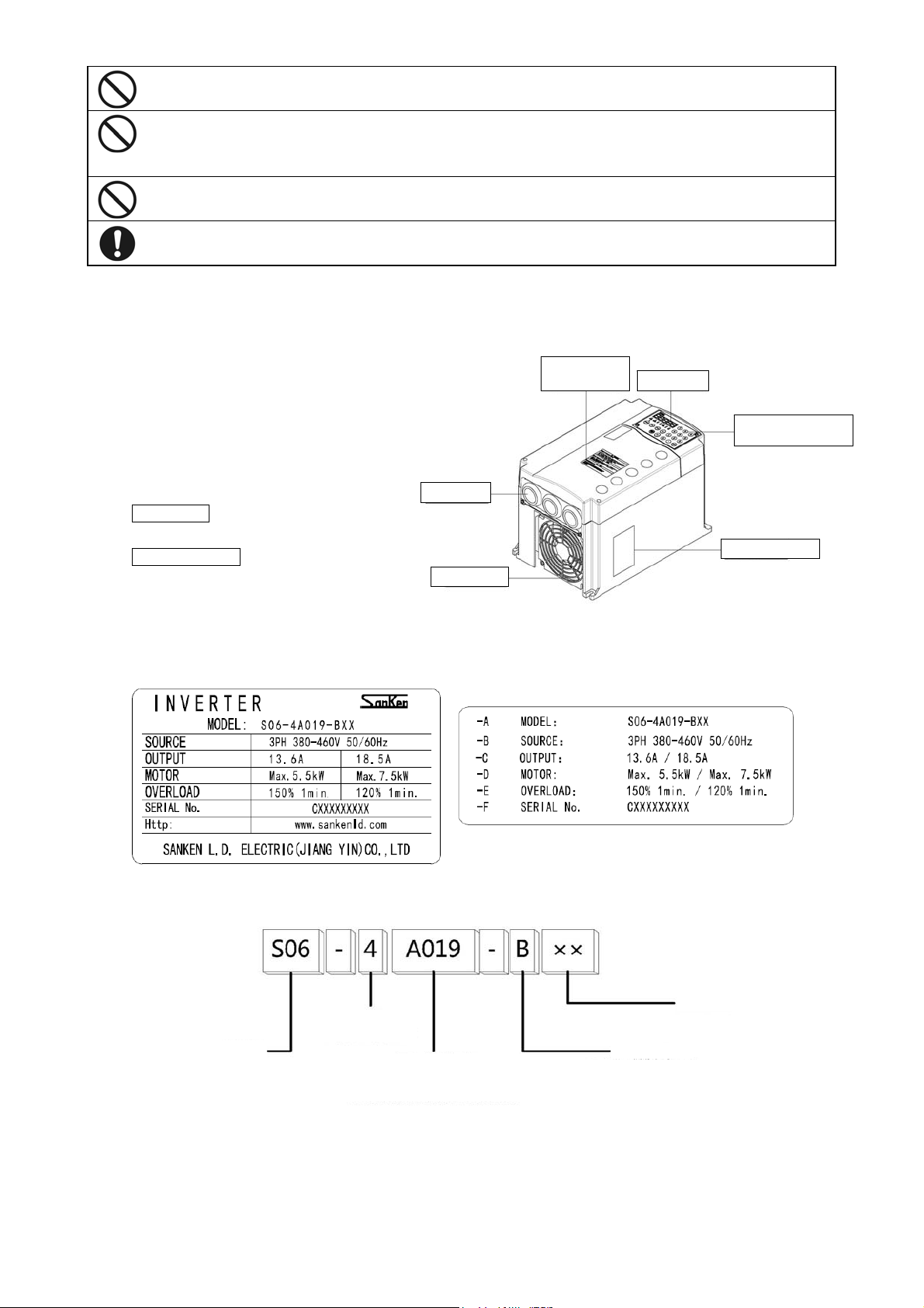
S06 series product body (take S06-4A019-B** for example)
Wiring hole
Inverter body
As shown on right
Instruction Manual
this manual
2-2 Example of nameplate label
Cooling fan
Warning
identification
LED monitor
Multifunctional
numeric ke
Nameplate label
s
2-3 The meanings of the model
Series name
2-4 Precautions on Use
1. Use the product in a location satisfying the standard environmental specifications (temperature, humidity, vibration, dust,
water drop, toxic gases, etc.).
2. Before starting up the product for the first time, carefully check the wiring. Make sure that the power cable (input) and
Voltage class
4: 3-phase 400V
Rated current calibration
For example: A019 represents the motor
capacity corresponding to the rated
current of 18.5A is 7.5kW
- 8 -
Internal code
Overload mode
B stands for light overload which can
work for 1 minute @ 120%

motor cable (output) are connected correctly. Otherwise, the inverter will be damaged.
3. Since the service life of the inverter is greatly affected by the ambient temperature of the installation location, it is
recommended to lower the ambient temperature before operation.
4. When installing the product in a control cabinet, check the cabinet size and ensure sufficient ventilation.
5. When the capacitors and surge suppressors used for improving the power factor are connected to the inverter’s output
terminal, the inverter may be heated or even damaged bacause of the high-order harmonic components. Therefore, do not
connect the capacitors and surge suppressors to the output terminal of the inverter. To increase the power factor, you can
install the DC reactor at the DC side or install the AC reactor at the primary side (i.e. input terminal) of the inverter.
6. When implementing a megger test, follow the method given in this instruction manual (10-4 “Megger Test”).
7. When using leakage circuit breaker protection switch, select a product for corresponding high-order harmonic and surge.
8. In principle, there is no magnetic contactor between the inverter and the motor. However, if the magnetic contactor is
turned ON and OFF while the inverter is operating, an excess current will be generated.
9. Select larger capacity since the operating characteristics of full electromagnetic-type MCCB changes with high-order
harmonic current.
- 9 -
3. Installation
(op
)
b
3-1 Installation Location and Storage
Table 3-1 Work Environment Parameters
Ambient temperature
Storage temperature
Relative humidity Below 95%RH (without dewing)
Altitude Below 3000m (decrease the current when exceeding 1000m)
Vibration Below 5.9m/s2 (0.6G) (JIS C 60068-2-6 standard; IEC60068-2-6)
Gaseous media Indoor (free of corrosive gas, flammable gase, oil mist, dust, etc.)
Table 3-2 Storage Environment
Storage temperature
Relative humidity Below 95%RH (without frost)
Storage environment Places free of direct sunlight, corrosive or inflammable gases, oil mist, dust, steam, water droplet,
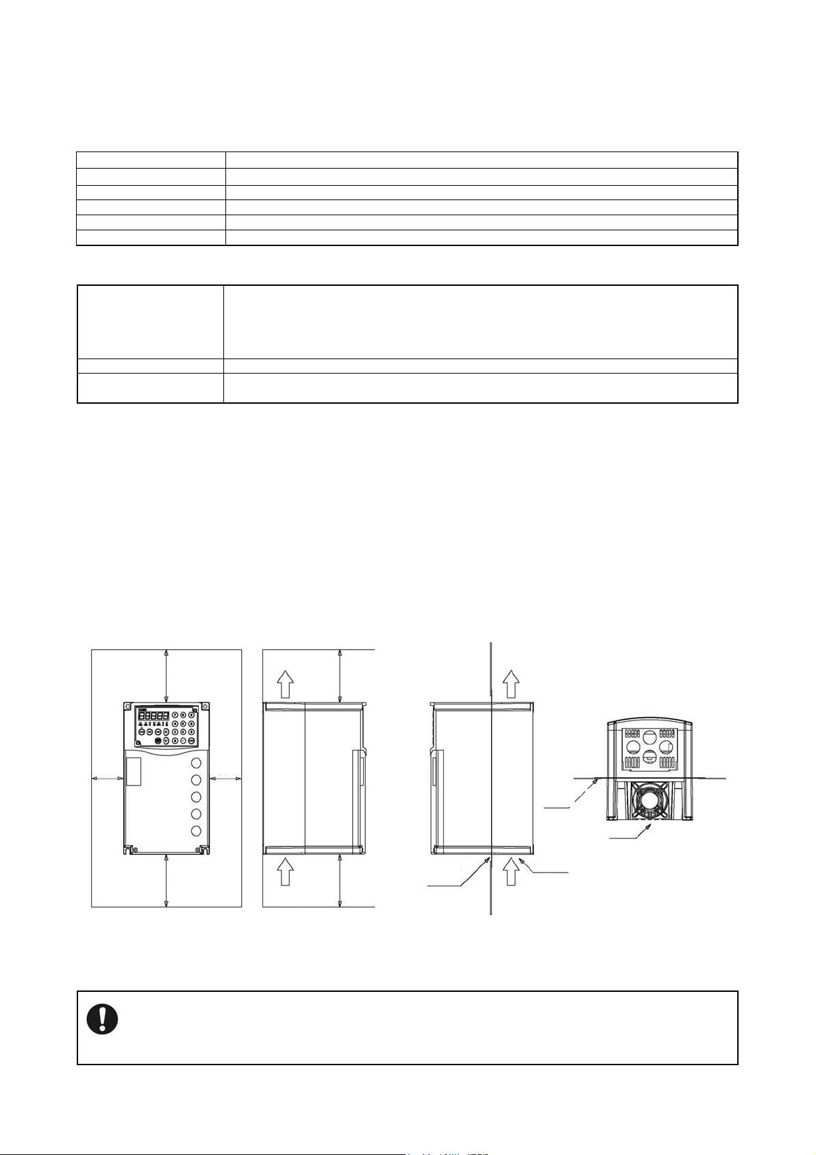
3-2 Installation Direction and Space
(1) This inverter is of the wall mounting type.
(2) Install the inverter vertically on a flat mounting surface.
-10℃~+50℃ (without freezing); heavy overload, -10℃~+40℃ (without freezing); light overload
-20℃~+65℃ (short-term preservation during transportation)
-20℃~+65℃
This temperature is for short periods, such as during transportation.
Ambient temperature must be 30°C or lower for more than 3 months of storage in consideration of
the deterioration of the electrolytic capacitor.
Furthermore, energize the equipment once per year when it is stored for more than one year.
vibration or high salinity.
(3) Since the inverter generates heat easily, provide adequate space around it to ensure good heat dissipation conditions.
(4) When installing the inverter in a control cabinet, provide a ventilation fan to keep the ambient temperature below 40°C.
(5) When installing the inverter in a control cabinet, mounting the radiator fins outside the control cabinet can help to reduce the
internal temperature of the cabinet.
(6) This inverter is of IP20 structure. Please select according to intended use.
Outside cabinet
Heating air
(optional)
Cooling fan
Cooling air
Mount
racket
Inside
cabinet
Outside
cabinet
Cooling fan
Above
5cm
Above 10cm
Above
Above 10cm
5cm
Heating air
Cooling air
Above 10cm
Above 10cm
Inside cabinet
Mount bracket
tional
Figure 3-1 Surrounding Space Figure 3-2 Arranging method of radiator fins
outside the cabinet
When several inverters are set in a control cabinet, be sure to locate the ventilation fans properly to allow free air
circulation.
Improper located ventilation fans will rise the ambient temperature, which will affect the cooling of the inverter.
- 10 -
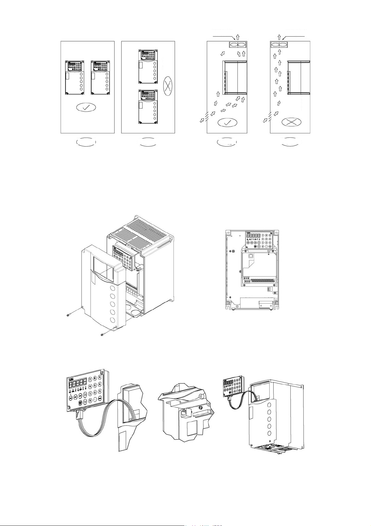
Ventilation fan
Overheat
Correct
Incorrect
Correct
Figure 3-3 Arranging method inside the cabinet Figure 3-4 Ventilation fan position in cabinet
3-3 Sketch of Front Cover Removal and Installation
(1) Removal of front cover (lower)
Unscrew the M4 screws, and pull the cover toward you while pressing both sides of the front cover (lower).
y Only carry out this work during the main circuit wiring, control circuit wiring and JP2 switching.
Ventilation fan
Overheat
Incorrect
(3) Removal of operation panel
Remove the operation panel and front panel during the installation, and re-install the front panel after the installation.
(2) Installation
When installing, work in reverse order.
- 11 -
4. Wiring
Read the Notes on Wiring (1-5) before wiring.
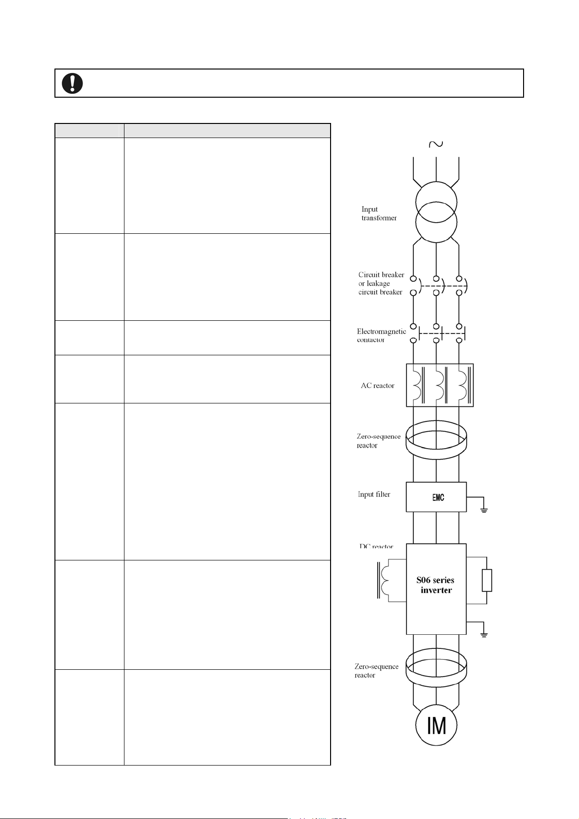
4-1 Connection with peripheral devices
Name Purposes and detailed description
Input power
supply
transformer
Circuit breaker
or leakage
circuit breaker
Failure to observe this may result in personal injury or fire.
When there is need for matching the system power
supply voltage with rated inverter input voltage, please
provide the input power supply transformer.
When several inverters are used, please provide the
input power supply transformer to reduce the impact of
high-order harmonic on other load devices.
Please connect wiring circuit breaker or leakage circuit
breaker in the overload protection circuit during
protection and wiring of the power supply system.
When using leakage circuit breaker, select a product for
corresponding high-order harmonic.
Electromagnetic
contactor
Surge absorber
AC reactor
DC reactor
Zero-sequence
reactor
Line noise filter
The coil must be provided with a surge absorber.
Please install the surge absorber for suppression of
surge generated on opening and closing of
electromagnetic contactors and control relays.
To achieve the following objectives, please install the
reactor
·Improve the inverter’s input power factor
·Reduce the impact on inverter due to unbalance
between phases of power supply voltage
·Prevent tripping of inverter due to action of phase lead
compensation capacitors in the system
·When the capacity of power supply is large (above
500kVA)
Reduce the interferences coming into input power
supply system of the inverter and generated by wiring.
It is recommended that elements such as zero-sequence
reactor etc. be inserted as close to inverter as possible.
Model name RC5078
Radio noise
filter
RC5096 [SOSHIN Electric Co., LTD]
Used to suppress the radio noise radiating to power
supply side of the inverter.
Model name 200V class: 3XYEB-105•104
400V class: 3XYHB-105•104
[OKAYA Electric Industries Co., LTD]
- 12 -
Reduce the interferences coming into input power
supply system of the inverter and generated by wiring.
Noise filter
It is recommended that noise filter be installed as close
to inverter as possible.
EMC filter recommended (please consult otherwise)
4-2 About Wiring
◆ Before carrying out wiring work, cut off the inverter’s input power supply, and make sure that no applied voltage
is present.
(1) Be sure to connnect a circuit breaker between the power supply and the input power supply terminals (R, S, T).
(Use a leakage circuit breaker specific to high-order harmonic when necessary.) To ensure the system safety,
connect a MC (electromagnetic contactor) between the circuit breaker and the input power supply.
(2) The phase order does not need to be considered when wiring the input power supply terminals (R, S and T).
(3) Connect the wires between the motor and the output terminals (U, V, W) correctly.
◆ The high-order harmonic leakage current increases accordingly when the total length of wiring between inverter
and motor is too long, which causes adverse affects on peripheral devices.
The total length of wiring between inverter and motor shall not exceed the values described in Table 4-1.
Table 4-1 Length of wiring between the inverter and the motor
Length of wiring between the inverter
and the motor
Carrier frequency
(Specified by F1009)
● When driving several motors at the same time, the total length of wiring to motors shall not exceed the values described
in Table 4-1. However, for vector control, the maximum wiring length shall be controlled within 100m. (For length of
more than 30m, please implement auto detecting mode 2)
● The surge voltage generated by the inverter element switching is superimposed and added to the motor terminal voltage.
The following measures should be considered to prevent deterioration of motor isolation especially for 400V class motors
when the length of wiring between the inverter and the motor is long.
① Use motors with reinforced isolation.
② Shorten the length of wiring between the inverter and the motor as possible (Generally about 10 - 20m).
(4) Refer to 4-5-4 for capacity of MCCB and MC as well as the wire sizes.
Use sleeved crimp terminals for the power and motor cables.
(5) Use shielded or twisted-pair wires for wiring to the control circuit terminals, while keep the wires well away
from the main and high-voltage circuits (including logic circuit of 200 V relay).
(6) Use a micro-signal contact or two-contact relay for the control circuit terminal to prevent poor contact.
(7) Ground the ground terminal ( ) securely.(Never use the casing or the chassis.)
According to technical standards for electrical equipment, 400V series shall be connected to the grounding
electrode for type C grounding.
Table 4-2 Types of grounding
Voltage Types of grounding Grounding resistance
400V series Type C grounding 10Ω or less
● Do not share the grounding wire with the welding machine or the power equipment.
● Use the grounding wire prescribed in the technical standards for electrical equipment, and shorten wiring length as much as
possible.
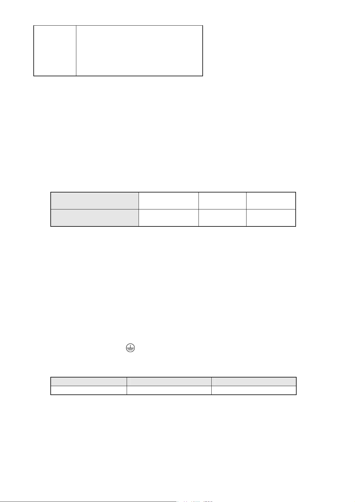
● Be careful not to loop the grounding wire when using multiple inverters.
50m 100m 200m
F1009=130 or less F1009=90 or less F1009=40 or less
- 13 -
(8) During wiring, please note that the inside of inverter shall be free from chips of wires.
◆ Control circuit wiring precautions
y Use shielded cable for analog input and output cables as well as the contact input cable (digital multifunctional input
terminals).
y To prevent misoperation due to interfenrence, the signal cables and power cables should be separated as possible during the
wiring (above 10cm).
y When using the operation panel for running, it can be realized only through the main circuit wiring (Without the need to
operate from the outside or by inputting frequency instructions).
y Connect the MCCB (circuit breaker) and other circuit protectors between the power supply and the input terminals.
y When the protective function of the inverter is enabled or the occurrence of other accidents, please connect the MC
(electromagnetic contactor) between MCCB and input terminals to cut off the inverter power supply, preventing further
expansion of failure or accident. Furthermore, the MC should be connected as close to the inverter as possible.
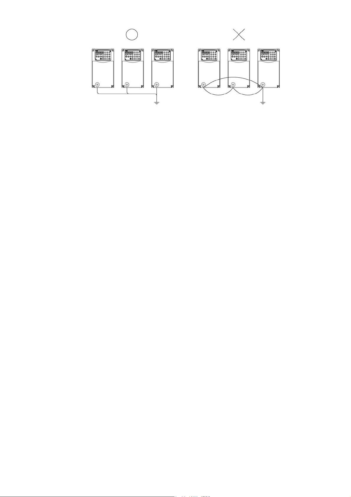
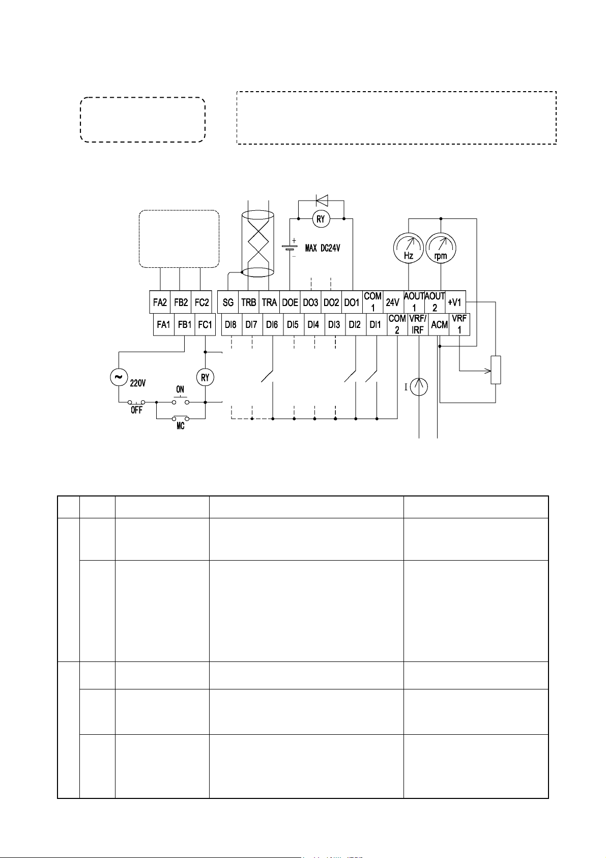
4-3 Terminal Wiring Diagram
- 14 -
Option
r
r
p
y
DC
reacto
Brake unit
Brake resisto
Input power
User load
Main circuit
Control circuit
Multifunctional input
terminal
Note: 5※
Digital signal
common ground
(internally
connected)
24V outside
ower output
Motor
Note: 1※
Multifunctional contact output 1
Contact capacity: 250V, 0.3A
Note: 2※
Multifunctional contact output 2
Contact capacity: 250V, 0.3A
Driving 1
Consistent
frequency
Overload prealarm
signal
Common
signal ground
Open collector
24V 50mA or less
Note: 3※
Potentiometer
Notes:
1: Ground ※ the inverter and motor reliably before use
2: Two groups ※ of separate multifunctional contact outputs, which can be selected and
set by F1513 & F1514
3: Multifunctional open collector output DO terminal, which can be selected and set b
F1509-F1511
4: Switch ※ the function with function code F1002. The terminal can be used as an input
terminal for various feedback signals
5: Multifunctional input terminal, can be assigned with different functions using ※
function code F1414 to F1421
6: This jumper terminal is used for version update, never use it under normal ※
circumstances
4-4 Composition of Main Circuit Terminals
Frequency setting power 12V
Frequency setting terminal
Frequency setting terminal
Analog signal common terminal 12G
Analog output DC0-10V
Analog output DC0-10V
Note: 4※
Update terminal
Note: 6※
※
RS485 communication terminal
Terminal resistor
Main circuit terminal
Control circuit input terminal
Control circuit output terminal
Communication circuit terminal
4-4-1 Description of Main Circuit Terminals
Terminal symbol Name Description
- 15 -
R,S,T Input power supply terminals Terminals connected to a three-phase commercial
r
r
r
power supply
U,V,W Inverter output terminals Terminals connected to a three-phase induction motor
P,P1 DC reactor connection terminals
P,PR Brake resistor connection terminals Terminals connected to a brake resistor between P-PR
P,X DC side voltage terminals
Ground terminal Terminal for grounding of inverter casing
Terminals connected to a DC reactor ※1
Terminals connected to a brake unit
P is the DC positive terminal, X the DC negative
terminal
※1 When connecting the DC reactor, please remove the jumper between P1 and P.
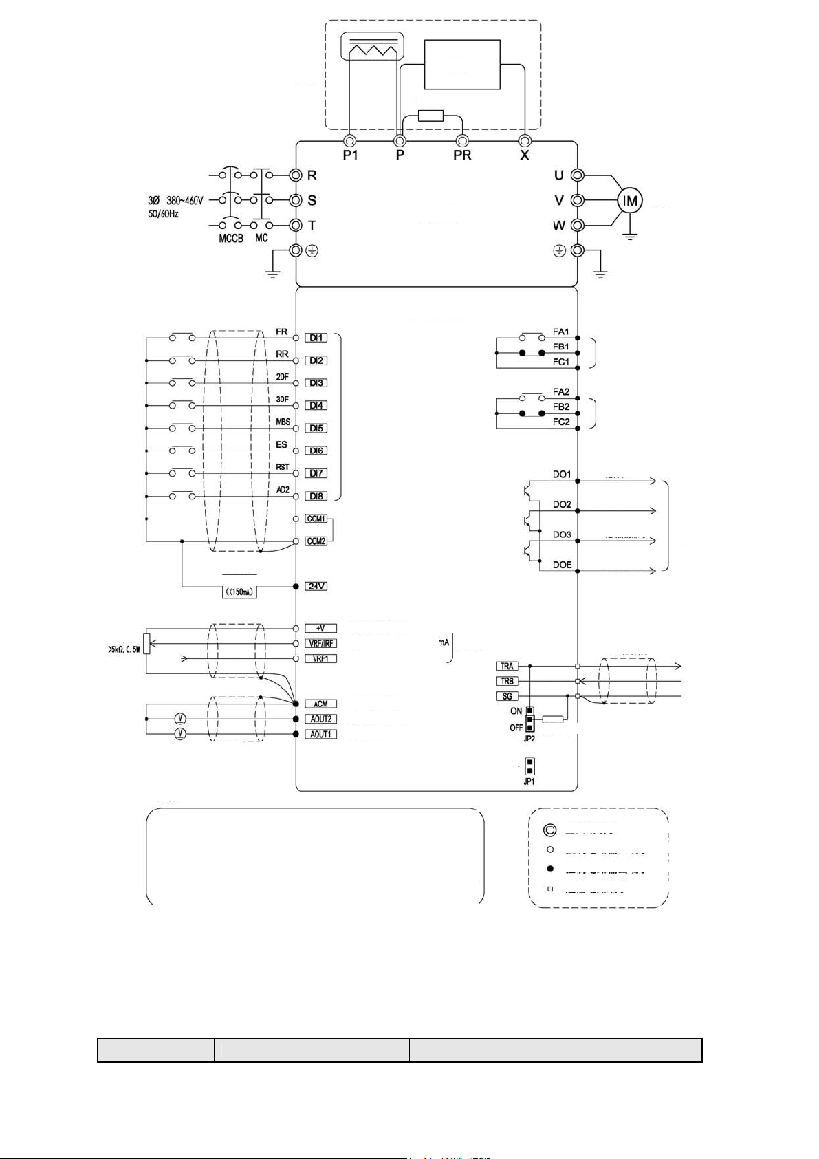
4-4-2 Connection Diagram of Main Circuit Terminals
(1) S06-4A005~4A076
Jumper
DC
reactor
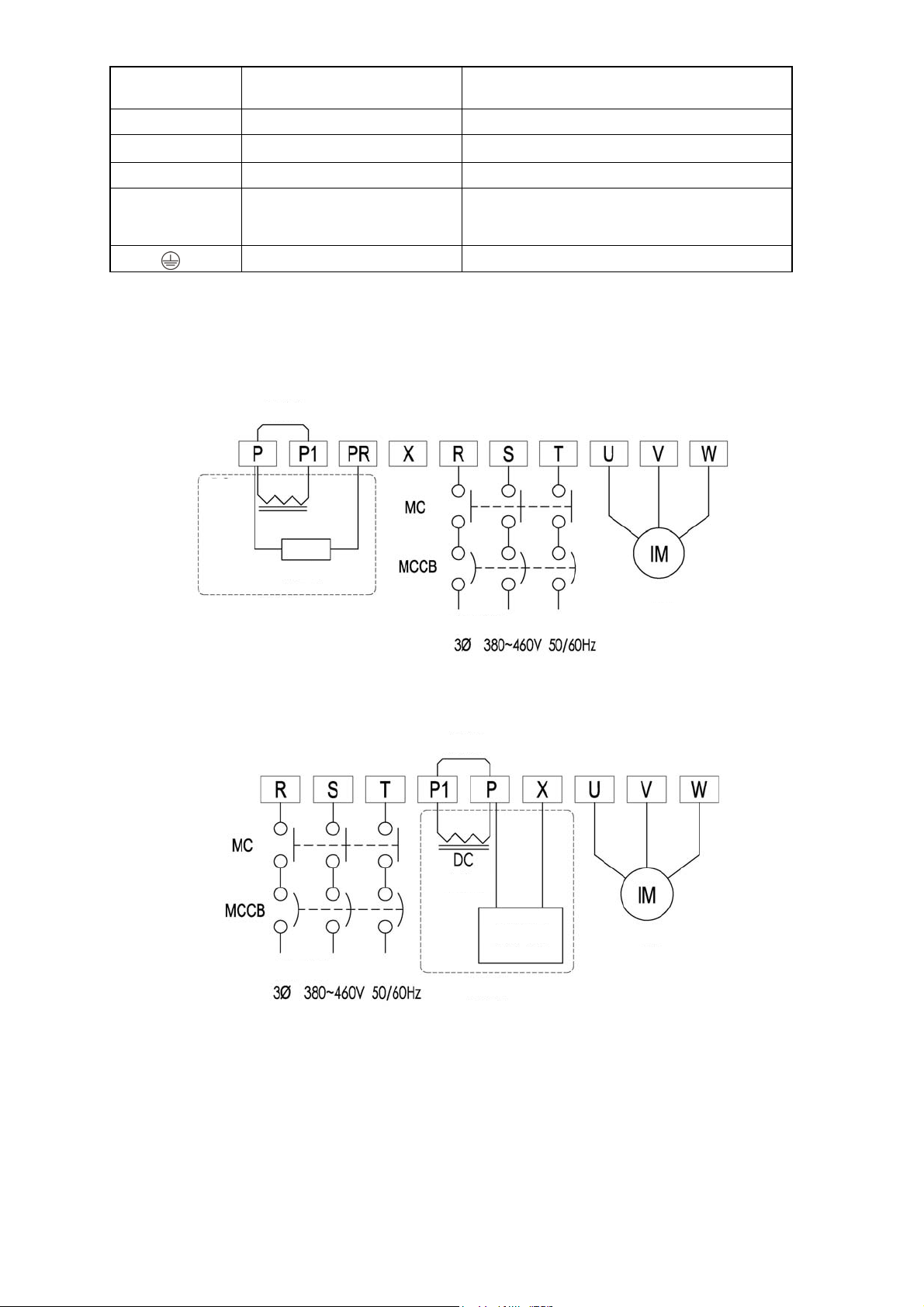
(2) S06-4A092~4A152
Brake resistor
Motor
Option
Input powe
Jumpe
Reacto
Brake unit Motor
Input power
Option
- 16 -
4-4-3 External brake resistor selection example
)
)
)
)
)
)
)
)
)
)
)
)
)
)
)
)
)
)
)
)
)
)
)
)
)
)
)
)
Model
S06-4A005-B** 700Ω or more 100W 420Ω or more 300W
S06-4A006-B** 320Ω or more 200W 190Ω or more 300W
S06-4A009-B** 160Ω or more 400W 130Ω or more 500W
S06-4A014-B** 120Ω or more 600W 80Ω or more 800W
S06-4A019-B** 80Ω or more 800W 52Ω or more 1100W
S06-4A025-B** 60Ω or more 1000W 38Ω or more 1500W
S06-4A032-B** 40Ω or more 1500W 32Ω or more 1800W
S06-4A038-B** 40Ω or more 1500W 32Ω or more 1800W
S06-4A049-B** 40Ω or more 1500W 32Ω or more 1800W
S06-4A061-B** 40Ω or more 1500W 32Ω or more 1800W
S06-4A076-B** 20Ω or more 3000W 16Ω or more 3600W
※1 The above brake resistor is selected by assuming the maximum duty cycle to be 10% ED. When % ED needs to be set above
10%, brake resistor capacity should be increased proportionally.
Example) When setting 20 % ED, the capacity should be doubled that of 10%ED.
External brake resistor (recommended) External brake resistor (limit value)
Resistance
Capacity ※1
Resistance
Capacity ※1
4-4-4 Capacities of MCCB and MC as well as Wire Size
Model MCCB
(Circuit
breaker)
[A]
(Electromagnetic
contactor)
Rated
current
[A]
MC
Rated
making
current
[A]
Recommended wire size [mm2]
Input wire P,P1 wires Output wire Ground
Main circuit
wire
Screw
diame
ter
Tighten
ing
Torque
[N•m]
Max. wire
size
[mm2]
S06-4A005-B** 5 7 20 2.0 (2.0
S06-4A006-B** 15 7 20 2.0 (2.0
S06-4A009-B** 20 7 20 2.0 (2.0
S06-4A014-B** 30 7 20 3.5 (2.0
S06-4A019-B** 30 17 32 5.5 (2.0
S06-4A025-B** 50 25 50 5.5 (2.0
S06-4A032-B** 60 25 50 8.0 (3.5
S06-4A038-B** 70 32 60 14 (5.5
S06-4A049-B** 75 48 80
S06-4A061-B** 100 65 100
S06-4A076-B** 125 75 135
S06-4A092-B** 150 75 135
S06-4A115-B** 175 150 200
S06-4A152-B** 225 150 200
Notes: The values for wires in the main circuit are for 600 V IV PVC-insulated wires (60ºC) when the inverter ambient
temperature is 40ºC. The values in parentheses are for 600 V bridged-polyethylene insulated wires (90ºC). The maximum
wire size indicates the maximum wire cross-sectional area that can be used with the terminal block.
14(5.5)
22(14)
38(14)
22×2(22)
60(38) 38(14) 22(14)
60(38) 60(22) 38(14)
2.0 (2.0
2.0 (2.0
2.0 (2.0
3.5 (2.0
5.5 (2.0
5.5 (2.0
8.0 (3.5
14 (5.5
22 (14
22 (14
22 (14
22 (14
2.0 (2.0
2.0 (2.0
2.0 (2.0
2.0 (2.0
3.5 (2.0
5.5 (2.0
8.0 (3.5
8.0 (3.5
8.0(5.5)
8.0(5.5)
14(5.5)
22(8)
M4 1.2 5.5
5.5
5.5
5.5
5.5
5.5
5.5
14
M5 2.0 14
14
14
M6 2.03 22
14
14
M6 4.52 60
22
22
22 M8 4.52 60
- 17 -
4-5 Composition of Control Circuit Terminals
d
4-5-1 Wire size and terminal arrangement
Terminal screw diameter:M3
Recommended wire size: 0.75[mm2]
Tightening torque:0.5[N•m]
※ The common end of control circuit terminals shall not be grounded to the earth.
※ COM1/COM2 shall not be in common use with ACM. (Because they are insulated with each other).
※ Do not input the voltage to multifunctional terminals (DI1-DI8).
4-5-2 Schematic of control circuit terminal wiring
RS485 communication
Other control
circuits composed
of relay 2-node
output
Surge suppressor
Single-phase
Emergency stop
4-5-3 Functional list of control circuit terminals
Ty
pe
Terminal
Symbol
COM
COM
DI1
DI2
DI3
DI4
DI5
DI6
①Multifunctional input
DI7
DI8
ACM
+V
②Analog input
VRF1
1
2
Terminal Name Function Description Rated Specification
Digital signal
common terminals
Digital
multifunctional input
Common terminals for digital input and output
signals and for +24V power supply
(1) The functions selected can be set through
function codes F1414~F1421.
terminals
Analog signal
common terminals
Analog input
potentiometer wiring
terminal
Common terminals for analog input and output
signals
Connected to a potentiometer of 5kΩ 0.3W or
above
z Carry out frequency setting through voltage
input
Analog voltage input
terminal
z Set the gain frequency corresponding to 5V
or 10V with voltage input.
z When “External analog forward / reverse
run” is selected, set the gain frequency
- 18 -
Reverse
Frequency
Forwar
RPM
display
display
Potentiometer
frequency setting
4-20mA input
Total current consumed:
100mA or less
Input resistor: about 6.6kΩ
When short-circuited: aboutDC3~
5mA
(1) Signal input “on” by
short-circuiting either COM1 or
COM2.
(2) Signal input “off” by opening
either COM1 or COM2.
Total current consumed: 100mA or
less
DC 10~12V
※It can not be connected to any
element other than the
potentiometer
Input resistor:
about 34kΩ
Maximum allowable voltage:
DC12V

corresponding to 10V (5+5V) or 0V (5-5V)
pp
y
p
with external analog value.
z The current/voltage in this channel can be
switched separately
z When frequency setting is selected, the
current/voltage input can be selected by the
Analog
current/voltage input
VRF
/IRF
l
24V Power supply output z Supply DC24V power to the user
su
③Power
terminals
(commonly used for
current/voltage input)
content of F1002.
z When carrying out frequency setting through
voltage input, set the gain frequency
corresponding to 5V or 10V with voltage
input.
z When “External analog forward / reverse
run” is selected, set the gain frequency
corresponding to 10V (5+5V) or 0V (5-5V)
with external analog value.
z When carrying out frequency setting through
current input, set the gain frequency
corresponding to 20mA.
For voltage input:
Input resistor: about 34kΩ
Maximum allowable voltage:
DC12V
For current input:
Input resistor: about 250Ω
Maximum allowable current: 30mA
Maximum allowable output current
for DC 24V: 150mA
Multifunctional
④Multifunctional
DOE
ut
DO1
out
DO2
DO3
AOU
AOU
⑤Analog output
TRA
TRB
⑥Communication terminal
FA1
FB1
FC1
FA2
FB2
FC2
⑦Contact output
output common
terminal
Multifunctional
output terminal
Analog output
T1
terminals
T2
RS485
communication
sending & receiving
terminals (+)
RS485
communication
sending & receiving
terminals (-)
RS485
communication
SG
common terminal
Abnormal alarm
signal output and
multifunctional
contact output
JP1 Upgrade jumper
z This terminal is DO1~DO3 shared
common terminal
z Open collector output
z Send signals through functions selected by
function codes
z Select the setting of signal output through
F1501~F1506
z Share the ground terminal with ACM analog
signal
z When connecting the computer using
RS485 communication interface, connect
the “+” signal terminal
z When connecting the computer using
RS485 communication interface, connect
the “-” signal terminal
z RS485 communication common terminal
z Connected to SG terminal on the
communication equipment
z These contact output terminals indicate that
the enabled protective function has stopped
the inverter.
z F1513, F1504: Select the setting for
multifunctional contact output according to
the relay 1 & 2 contact output
Used for short-circuiting during version upgrade
Allowable load: DC48V, 50mA
Signal output: DC 0~10V
Maximum output current: 15mA
Communication speed:
1200-57600bps
Total length: 500m
※When switch JP2 is located at
ON, connect the terminal resistor:
100Ω
※Choose the single terminal
grounding on inverter side or
communication equipment side
according to the site conditions
Contact capacity: AC250V/0.3A
When alarm contact is selected:
Normal: FA1,2-FC1,2 open
Abnormal: FA1,2-FC1,2 closed
※Do not connect anything to this
terminal except when upgrading.
Communication
JP2
⑧Jumper
terminal resistor ON
selector jumper
Choose whether to connect 100Ω terminal
resistor
- 19 -
OFF: terminal resistor is open
ON: terminal resistor is closed
4-5-4 Descriptions on control circuit terminal wiring
① Multifunctional input terminals
Digital multifunctional input terminals of DI1 - DI8 can be set to any one of the functions by using the function codes F1414 -
F1421 corresponding to various functions. In addition, a multiplexed terminal may have several functions.
When the function code is set to F1414=13, for example, the jog operation can be enabled simply by turning the DI1 terminal
on.
Table 4-4 List of multifunctional input codes
Function code No.
F1414 DI1
Input terminal
name
Data range Initial value (symbol)
1 (FR)
F1415 DI2 2 (RR)
F1416 DI3 3 (2DF)
F1417 DI4 4 (3DF)
F1418 DI5 5 (MBS)
0~255
F1419 DI6 6 (ES)
F1420 DI7 7 (RST)
F1421 DI8
8 (AD2)
※Refer to the description of selection functions of the input terminals DI1 - DI8 for details.
② Analog input terminals
1) Potentiometer for frequency setting
x The analog input has two channels: VRF1 voltage input and VRF/IRF voltage or current. They can be connected to the
potentiometer respectively, whose power supply terminal is +V common terminal and the ground terminal is ACM.
x Please install one 5kΩ potentiometer of 0.3W or above, and select the function code F1002: set the 1-speed frequency,
select the settings of current and voltage frequency.
x Use shielded cables for wiring, the control terminal shielding end should be connected to ACM shielded terminal, while
the other end will be left unconnected.
2) 4~20mA current for frequency setting
· Input the external 4~20mA control current through the VRF/IRF terminal and ACM, current direction: enter from
VRF/IRF and exit from ACM.
· By selecting function code F1002: set the 1-speed frequency, select the settings of current and voltage frequency.
③ 24V power terminal
· Provide the users with a DC24V power supply, which is used to connect encoders, transmitters or sensors, the
maximum load current should not exceed 150mA.
· Avoid overload or short circuit, otherwise it may result in damages.
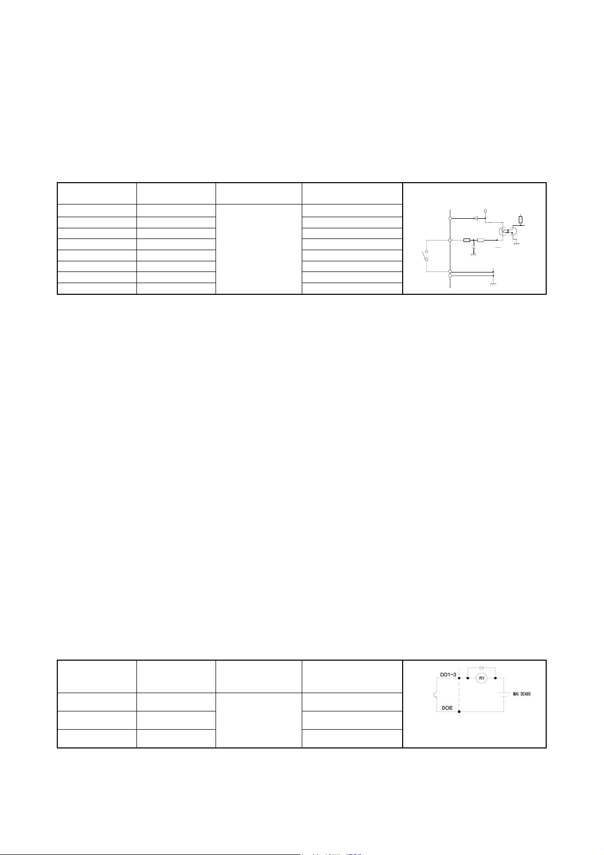
④ Multifunctional output terminal
· Digital multifunctional output terminals of DO1 - DO3 can be set to open collector output for any one of the functions by
using the function codes F1509 - F1511 corresponding to various functions.
x The multifunctional output terminal is the open collector output terminal, with a maximum voltage of 48V and a
maximum current of 50mA.
※ When using relays and other elements, be sure to install a surge suppressor (diode, reverse-parallel).
24V
DI1~
DI8
COM1
COM2
24V
COM
Table 4-5 List of multifunctional output codes
Function code No.
Input terminal
name
F1509 DO1
F1510 DO2
F1511 DO3
Data range
0~99
Initial value (function)
※
1(driving 1)
5(consistent frequency)
8(overload pre-alarm)
※Refer to the description of selection functions of DO1 - DO3 for details.
⑤ RS485 communication terminals
x The communication control with peripheral devices can be realized by using RS485 communication terminal block on the
- 20 -
following main control board.
x JP2 is a switch for turning ON / OFF the terminating resistor. Please set only the farthest terminating resistor switch of
the inverter to ON. (Factory preset= OFF: terminating resistor OPEN).
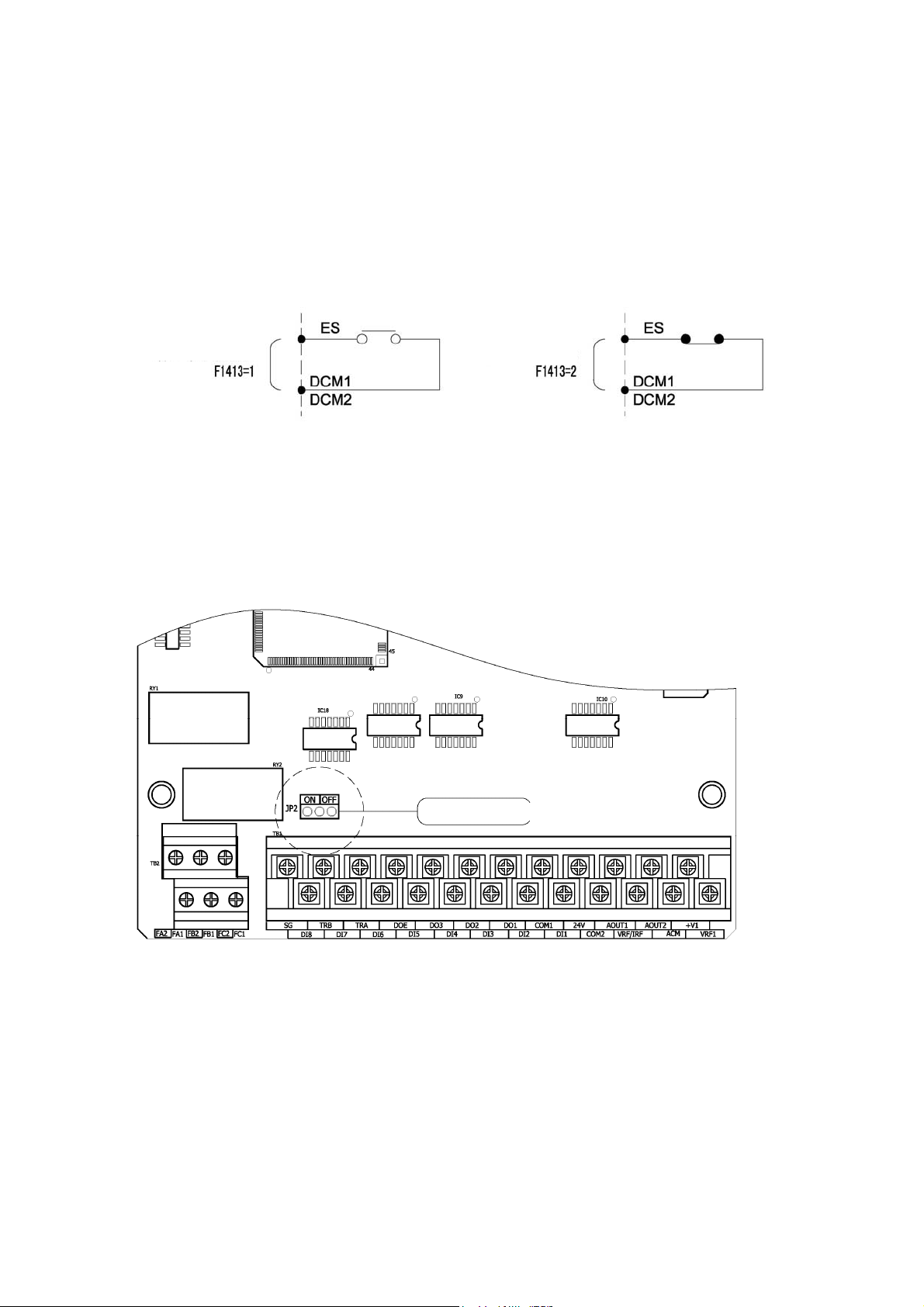
⑥ Contact output terminals
1) Signal mode switching for emergency stop (multifunctional input ES terminal)
x The figure below shows an example of signal switching when the multifunctional input terminal is set for the external
emergency stop (ES) command.
x A signal action is selected using the function code F1413: ES input terminal function.
When “normally open”
signal is input:
⑦ Jumper (JP2 communication terminal resistor ON selector jumper)
x When several inverters are communicating, place the JP2 of the farthest inverter into ON position, the terminal resistor
now will be connected, while its factory setting is OFF.
When “normally
closed” signal is
input:
Terminal resistor selector switch
- 21 -
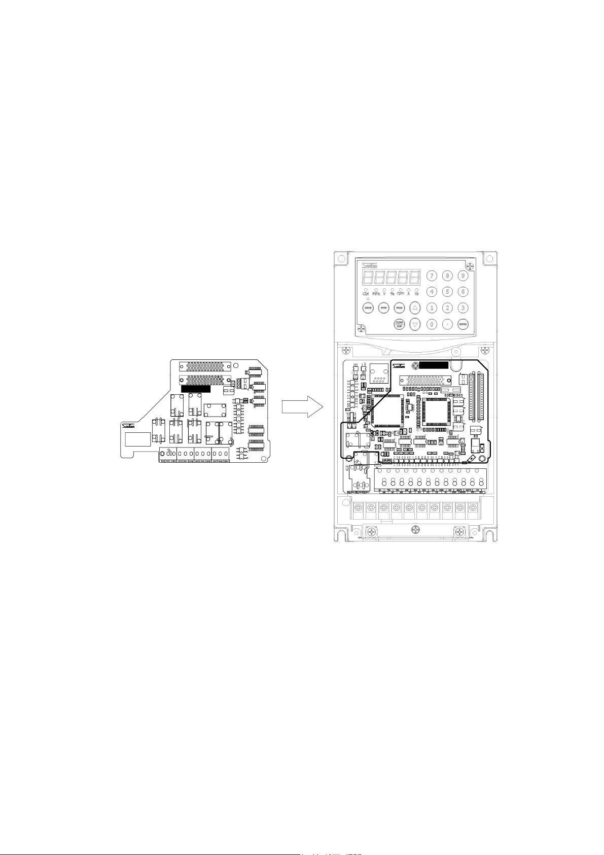
4-6 Installation and Wiring of Optional Board
4-6-1 Overview of Optional Board
Two optional boards can be installed on one inverter at the same time.
The shape of optional board may vary between different optional boards.
And sometimes, combination status of the optional board may also have impacts on installation and functions.
Refer to the instruction manual of each optional board for detailed functions of each optional board.
4-6-2 Installation Method of Optional Board
Remove the front cover before installing or removing an optional board.
When inserting an optional board into the slot, check if the connection between the mainframe side connector and the optional
board side connector is firm and reliable.
After the optional board has been installed, fix the optional board with attached screws (M3).
Shielded wires shall be used for wiring connected to terminals, with each common terminal connected to the shield.
Wiring shall be carried out according to the instruction manual of each optional board.
- 22 -
5. Operation Panel
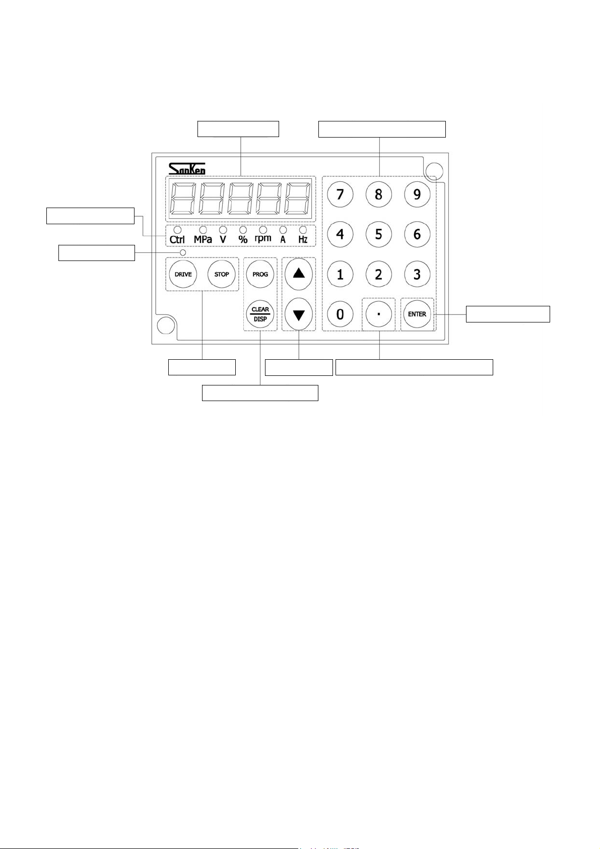
5-1 Names and Functions of Parts of the Operation Panel
LED status display
DRIVING display
For ease of operation, this series of inverters configure a numeric key panel as standard, to bring you the
following ease and convenience:
The numeric keypad with 0-9 decimal number input, even with the 0-F hexadecimal number input, can directly
While the 5-digit 7-segement LED tube, through the switching of DISP key, can clearly display the current
Using the light on/off/flashing statuses, the LED status indicator lamp can directly indicate the content and unit of
Furthermore, the in-control indicator (Ctrl) will display the status of external terminal driving/driving except
The DRIVING indicator lamp on the [DRIVE] button will turn on/off to indicate the DRIVE/STOP status, or will
The independent DRIVE/STOP key makes it easier to drive and stop the equipment.
The independent UP/DOWN key can also adjust the frequency or change the code through direct operations when
5-digit LED tube
Drive/Stop key
Combined programming key
input the parameter code, change the parameter settings, as well as set and modify the operation frequency very
easily.
operating frequency, input current, speed, load factor, output voltage, pressure, unit-free display value, setting
value and the alarm content.
7-segment LED tube, such as: frequency (Hz), output current (A), speed (Rpm), load factor (%), output voltage
(V) and the pressure (MPa).
external terminals.
flash to indicate STANDBY/DECELERATION/DC BRAKE and other status.
entering the numbers.
Up/Down key
Multifunctional numeric key
Enter/Confirm key
Decimal point hexadecimal switching
- 23 -
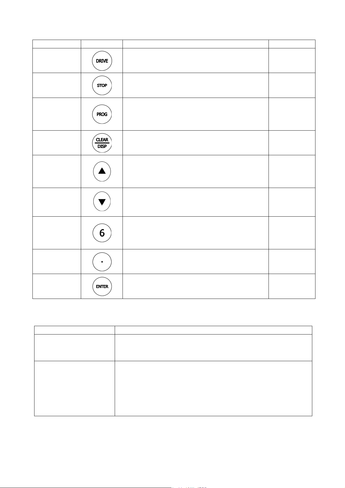
5-2 Description of keys on operation panel
Key Name Key Symbol Function Summary Shorted as
DRIVE key
STOP key
PROG key
CLEAR/
DISPLAY
switching
UP key
DOWN key
NUMBER key
(0-9)
DOT key
z Starts forward or reverse running operation.
z Stop operation
z Can be used for releasing alarm signal in alarm condition.
z In Status Display mode, change the Status Display mode to
Function Code Display mode
z In Function Code Display mode, return to the menu state of
previous page
z In Status Display mode, change contents displayed on the
7-segment monitor.
z In Function Code Display mode, clear the entered contents
z In Status Display mode, increase the frequency
z In Function Code Display mode, increase the code
z Can be used as “+” input for inputs with symbols
z Confirm some code setting
z In Status Display mode, decrease the frequence
z In Function Code Display mode, decrease the code
z Can be used as “-” input for inputs with symbols
z In Status Display mode, can be used to enter the frequency
directly
z In Function Code Display mode, can be used to enter the
code data directly
z Enter decimal point
z Combined with the numeric keys to enter the hexadecimal
codes of A-F
【DRIVE】
【STOP】
【PROG】
【CLEAR/DISP】
【UP】
【DOWN】
【0-9】
【DOT】
ENTER/CONFIRM
key
z Confirm the values displayed on 7-segment monitor which
will be entered into the host
【ENTER】
5-3 Display mode of operation panel
The operation panel 7-segment LED monitor has two display modes: [Status display mode] and [function code display mode],
and the modes can be switched by pressing the [PROG] key
Display mode Display contents
Status Display The inverter status during DRIVE and STOP
<Frequency> <Output Current> <Speed> <Load Factor> <Output Voltage>
<Pressure> <Uint-free Value>
Function Code Display Code number and data
Such as: Press [PROG] key to display F , enter “1202”
Display code F1202 (status display content selection)
Press [ENTER] to view the codes
Display 1 (Default display without unit)
Enter options via numeric key: such as “2” (output voltage)
After the setup is completed, the panel will display output voltage by default
The Status Display mode can carry out the inverter status monitoring, alarm display, output frequency setting as well as the
inverter DRIVE or STOP and other operations.
5-3-1 Version Display
Shortly after the power-on of the equipment, the software version of inverter will be displayed on 7-segment monitor. The
- 24 -
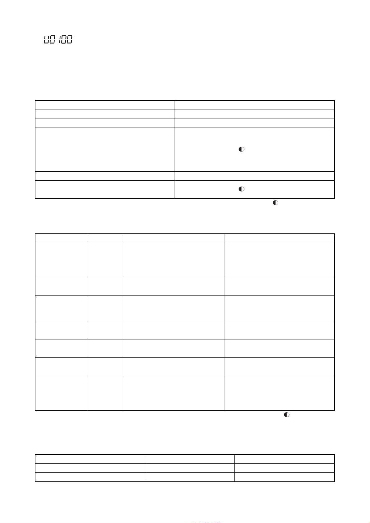
following is: display example for software version: VER 1.00.
If, for some reason, the host can not communicate with the operation panel when connected to the power, the 7-segment monitor
will display the software version of the operation panel. Now the monitor displays PXXXX.
5-3-2 Inverter status mode
The inverter status mode will be displayed.
In the operation mode display, various operation and stop states of the inverter are displayed.
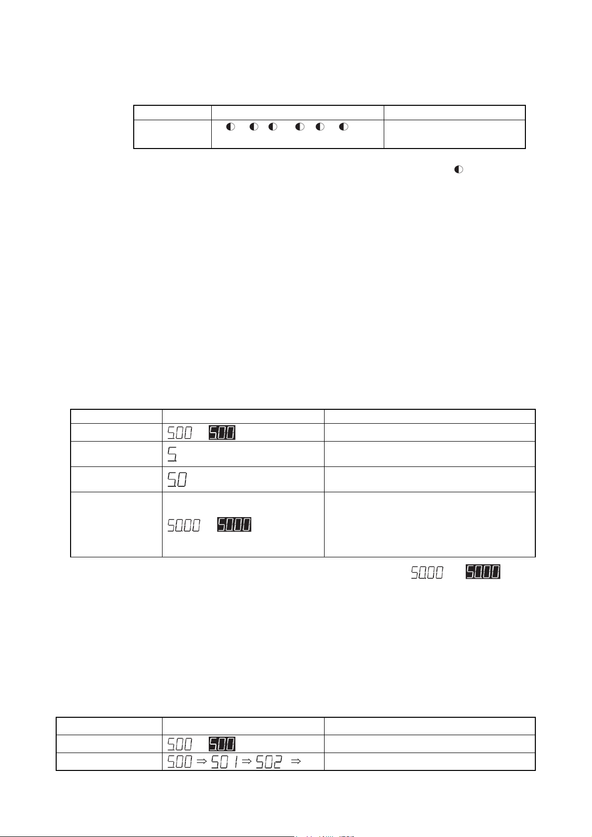
Table 5-2 Display contents of operation mode
Operation Status Display Contents
Stopped z Running indicator
Driven { Running indicator
Deceleration to stop from forward run
Forward run waiting
Deceleration to stop from reverse run
Reverse run waiting
DC braking (reverse)
Frequency locking { Running indicator
Position control running
(Zero-servo running)
Monitor mode display refers to the contents displayed on the 7-segment monitor
Table 5-3 Display contents of monitor mode
Display Contents Unit Display Contents Display of 7-segment Monitor
Frequency Hz {Hz zA zrpm z% zV zMPa
Output current A zHz {A zrpm z% zV zMPa
Speed rpm zHz zA {rpm z% zV zMPa
Load factor % zHz zA zrpm {% zV zMPa
Output voltage V zHz zA zrpm z% {V zMPa
Pressure (option) MPa zHz zA zrpm z% zV {MPa
Status monitor
display
(No unit)
※1 Depending on the motor control modes, the display contents may be somewhat different. The display contents are as shown
in Table 5-4
Table 5-4 Display contents of speed
Motor control mode Running Stopped
Sensorless vector control Estimated speed of motor 0
Others Detecting speed of PG sensor Detecting speed of PG sensor
- zHz zA zrpm z% zV zMPa
Running indicator
Running indicator
{ Lit Flashing z Unlit
Running: the lit lamp indicates output
frequency
Stopped: the flashing lamp indicates setting
frequency
Running: the lit lamp indicates output current
Stopped: the flashing lamp indicates 0.0
Running: the lit lamp indicates speed (※1)
Stopped: the flashing lamp indicates speed
(※1)
Running: the lit lamp indicates load factor
Stopped: the flashing lamp indicates 0.0
Running: the lit lamp indicates output voltage
Stopped: the flashing lamp indicates 0.0
Running: the lit lamp indicates pressure
Stopped: the flashing lamp indicates 0.0
Running: the lit lamp indicates the values
selected by F1202
Stopped: the flashing lamp indicates the
values selected by F1202
{ Lit Flashing z Unlit
- 25 -

(V/f, vector etc.)
During the inverter’s status monitoring display, display contents of 7-segment monitor are shifted every time when the
[CLEAR/DISP] key is pressed. Display contents of 7-segment monitor can also be shifted through function codes. Refer to the
function code F1201 in [7-3 Description of Functions] for details.
※ Refer to the function code F1101 in [7-3 Description of Functions] for details of the operation command from an external
terminal / operation command from communication.
※ Sometimes this function is not available if set through the inverter’s function code.
- 26 -
5-3-3 Alarm display
When the alarm has stopped, the type of alarm will be displayed on the 7-segment monitor of the inverter. At this point, the
monitor mode displays that all the LEDs are flashing. See [8-4 Alarm Status] for the details of alarm display.
Display Contents Monitor mode display 7-segment Monitor Displays
Alarm display Hz A rpm % V MPa The type of an alarm is indicated by
the lamp
{ Lit
※ During alarm display, the display on 7-segment monitor can not be switched even by pressing [CLEAR/DISP] key.
※ During alarm display, pressing [PROG] key can switch current display to function code display mode.
Flashing z Unlit
5-3-4 Frequency input
The frequency setting of the inverter can be input by using the numeric keys, [UP]/[DOWN] and [ENTER] keys, the following
are the two setting methods.
(1) Frequency setting A
Press the numeric keypad to modify the frequency to be set, then press [ENTER] key to confirm, this is the method of
frequency setting A.
x This is an effective method for setting a desired frequency.
x Cancellation can be made during frequency setting.
x In status monitor display, the method of frequency setting A can be used either in running or stopped state of the
equipment.
x This method can not be used during alarm display.
Operation example: changing from 5 Hz to 50 Hz
Operation Display Description
【5】
【0】
[ENTER] (press)
※1 If it is not necessary to set frequency, press [CLEAR/DISP] key to return to the status monitor display mode.
(2) Frequency setting B
Frequency setting B is a method for changing frequency by pressing [UP] / [DOWN] each time.
or
or
Display of status monitor (frequency display)
The value to be entered will be displayed on the
rightmost (※1)
The displayed data will move one digit to the left at
each time when the numeric key is pressed (※1)
Press this key, then the set value will be stored as a new
frequency value.
And the interface will return to status monitor display
mode. If this is done during running operation, then the
output frequency will start to change to the newly set
value.
Lit;
Flashing
x This is an effective method for fine-tuning of the set frequency during observation of the load conditions.
x In status monitor display, this method can be used either in running or stopped state of the equipment.
x This method can not be used during alarm display.
Operation example: changing the frequency from 5 Hz to 50 Hz
Operation Display
[UP] / [DOWN]
or
…
Display of status monitor (frequency display)
Press [UP] / [DOWN], and the value displayed will
Description
- 27 -

increase or decrease. The frequency changed will be
stored immediately as a new frequency value. If this is
done during running operation, then the output
frequency will start to change to the newly set value.
Lit;
The function code display mode can be used to set various functions of the inverter.
5-4 Basic operation
5-4-1 Setting function code
The basic operation is used for changing the value of a function code.
Operation example: setting F1414=10
Operation Display Description
[PROG]
Numeric key input
[1] [4] [0] [1]
Press [ENTER]
[UP]/[DOWN] or numeric
key[1] [0]
[ENTER]
[CLEAR/DISP]
[PROG]
※1 Use [UP]/[DOWN] can accurately index the values that can be set, ensuring that the input is valid, while you can not do this
using the numeric keys.
※2 If a new value is not required, the display can be returned back to the status monitor mode through the [PROG] key.
or
or
Display of status monitor (frequency display)
Press [PROG] key to display the function code input
interface
Enter the target function code, or use [UP] / [DOWN] to
adjust the current input
Press [ENTER] key to display the setting values of the
function code
Press [UP] / [DOWN], or press the numeric key to set the
target value (※1)
Press the [ENTER] or [PROG] key to confirm the new
setting, and the display screen will return to function code
selection.(※2)
Press [CLEAR/DISP] key to return the display screen to the
function code input interface
Press [PROG] key to return the display screen to status
monitor mode
Flashing
5-4-2 Confirming operation
For some function codes, operation needs to be re-confirmed to prevent data rewriting due to misoperation.
Operation example: setting F1001=10
Operation Display Description
[PROG]
Numeric key input
[1] [0] [0] [1]
[ENTER]
[UP]/[DOWN] or numeric
key[1] [0]
[ENTER]
[UP]
or
Display of status monitor (frequency display)
Press [PROG] key to display the function code input
interface
Enter the target function code, or use [UP] / [DOWN] to
adjust the current input
Press [ENTER] key, the monitor will display the setting
values of function code.
Modify the newly set value, the decimal point is invalid
Press [ENTER] key, the setting value and the
be display alternately, prompting the setting value is being
confirmed (※1)
Press [UP] again, the new setting will be confirmed and the
monitor will return to the function code selection interface
(※2)
will
- 28 -
[CLEAR/DISP]
[PROG]
※1 During alternate display period, if it is desired to interrupt input as any mistake in operation is found, press the
[CLEAR/DISP] key to return the display to the function code selection state.
※2 Press [PROG] key to return to the status monitor screen directly.
or
Press [CLEAR/DISP] key to return the display screen to the
function code input interface
Press [PROG] key to return the display screen to status
monitor mode
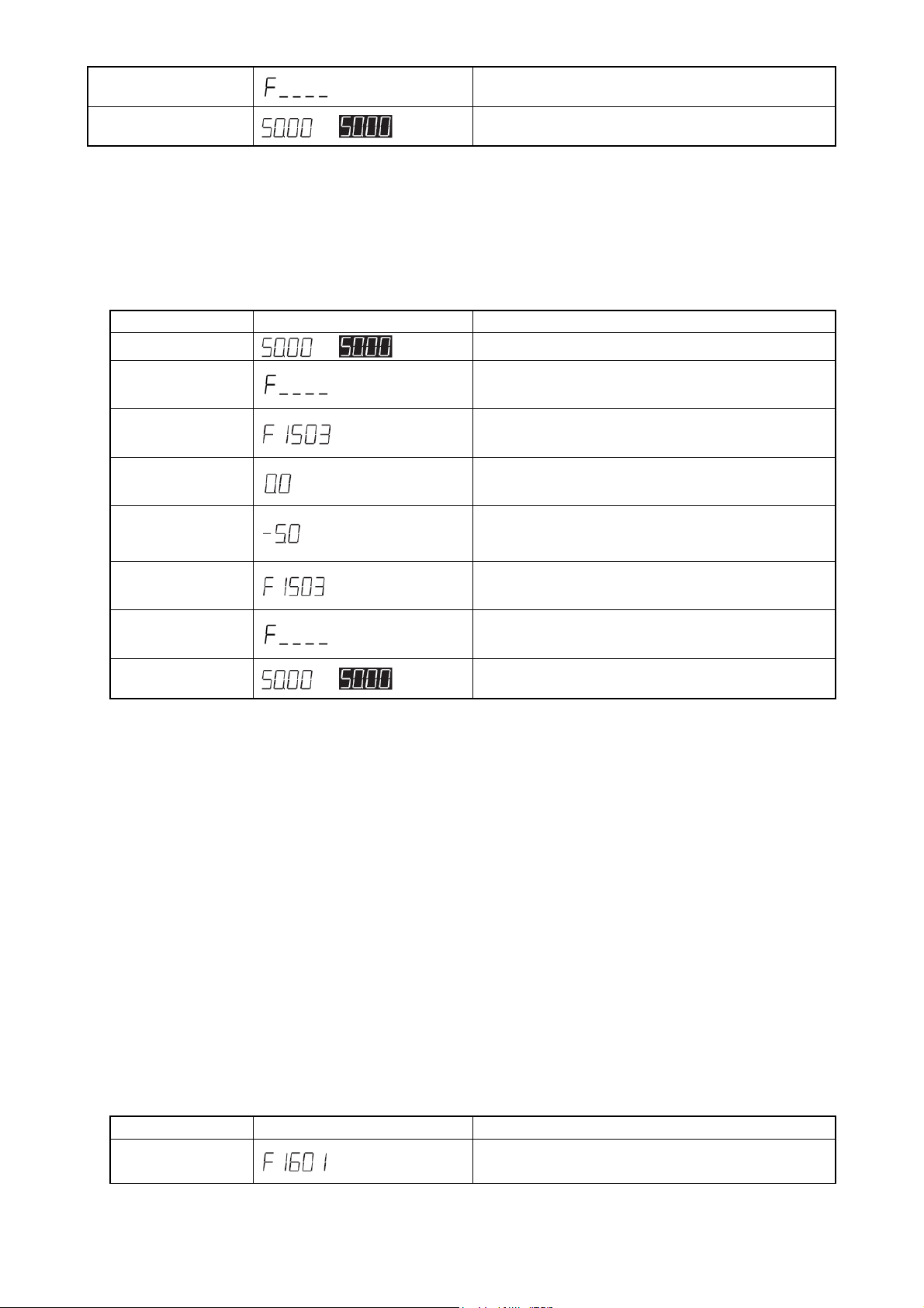
5-4-3 Signed operation
For some function codes, they can be set with values containing signs (polarity).
Operation example: setting F1503=-5.0
Operation Display Description
[PROG]
or
Display of status monitor (frequency display)
Press [PROG] key to display the function code input
interface
Numeric key input
[1] [5] [0] [3]
[ENTER]
Numeric key input
[5] [DOT] [0]
[DOWN]
[ENTER]
[CLEAR/DISP]
[PROG]
※ 1 Press [CLEAR/DISP] key to return back to the function code selection interface, the setting will be cleared without being
※ 2 Press [PROG] key to return to the status monitor mode directly.
saved.
or
Enter the target function code, or use [UP] / [DOWN] to
adjust the current input
Press [ENTER] or [PROG], the monitor will display the
setting values of function code.
Modify the newly set value, [DOWN] key is used for sign
switching
(※1)
Press the [ENTER] key to confirm the new setting, and the
display will return to function code selection interface. (※2)
Press [CLEAR/DISP] key, the monitor will return to the
function code input interface
Press the [PROG] key, and the monitor will return to status
monitor mode interface.
5-5 Special functions
5-5-1 Copy function operation
The so-called copy function is the function which transfers the function code data to other inverters after transferring the function
code data from one inverter side to the operation panel.
The copy function is an effective function where several inverters need to be set with the same function code data.
Only 1 inverter is set, while other inverters can also receive the same function code data, thus the same function code setting can
be easily implemented.
※ The copy function can be implemented only when the inverter stops working. Therefore, this operation shall be carried
out after the inverter has been stopped.
Operation example: copying from the inverter to the operation panel
Operation Display Description
Input or select function code F1610 (copy function)
- 29 -

[ENTER]
[UP]/[DOWN] or
numeric key[1]
[ENTER]
[UP]
After transfer is
completed
Refer to the contents of function code F1601 in [7-3 Description of Functions] for detailed description of the function and its
operation method.
Press the [ENTER] key to display the setting value of
function code.
Select 1
When F1601 = 1, the current value of the function code data
will be transferred to the operation panel
Wait for confirmation
The data transfering starts when a flashing COPY is
displayed on the 7-segment monitor
When data transfer is completed, the display will return to
function code selection interface.
5-5-2 Changed code display operation
Considering current function code data may be different from the factory presets of product or the user's initial value, the function
for displaying a changed function code and its data has been provided.
This is an effective function for inquiring the difference between current function code and product’s factory preset or the user
initial value.
Confirmation of maintenance and other function codes can be easily achieved by this function.
Operation example: displaying data which are different from product’s factory preset data
Operation Display Description
[ENTER]
[UP]/[DOWN] or
numeric key
[ENTER]
After searching
[UP]/[DOWN]
[ENTER]
[CLEAR/DISP]
[CLEAR/DISP]
Refter to the contents of function code F1602 in [7-3 Description of Functions] for detailed description of the function and its
operation method.
or
or
Select function code F1602 (changed code display function)
Press [ENTER] key, then the setting value of function code will be
displayed.
Press the [UP]/[DOWN] or numeric key to select 1
If F1602 = 1, the current function code data will be compared with the
factory preset function code data.
Press the [ENTER] key to start searching the number of a function
code which has been changed and is different from the factory preset
function code data. While the function is searching, a flashing
will be displayed on 7-segment monitor.
After searching, the changed function code starts flashing on display
screen.
If there is no changed function code, a flashing
displayed on screen.
If there are more than one changed function codes, they can be
switched by adjusting the quick knob.
Press the [ENTER] key, then the set value of function code will be
displayed flashing.
Press the [CLEAR/DISP] key to return to the changed function code
(flashing display state)
Press the [CLEAR/DISP] key to return to function code selection
interface.
will be
5-5-3 Function code initialization operation
The inverter’s function code settings can be returned to factory presets through this function.
Inverter’s initial value can be set to the factory preset or the data determined by the user (i.e. user’s initial value). Also, the initial
value can be selected between the factory presets and the user’s initial value. By setting the user’s initial value, the function code
data can be initialized to the user’s initial value even if it is overwritten for some reason, allowing for resetting the function code
- 30 -

within a minimum range.
Operation example: recovering to the factory presets
Operation Display Description
[ENTER]
[UP]/[DOWN] or
numeric key
[ENTER]
[UP]
After initialization
Refer to the contents of function code F1604 in [7-3 Description of Functions] for detailed description of the function and its
operation method.
※1: In the alternate display, if an operation error occurs and it is hoped to interrupt input, then the interface can be
returned to the function code selection state by pressing the [CLEAR/DISP] key.
Select function code F1604 (data initialization)
Press [ENTER] key, then the setting value of function code will be
displayed.
Press the [UP]/[DOWN] or numeric key to select 1
If F1604 = 1, all the function code data will recover to the factory
presets
Pressed the [ENTER] key, then the setting value and
displayed alternately, suggesting that the setting is being confirmed (※
1)
Press the [UP] key to start initialization of the function code. During
initialization, a flashing will be displayed on 7-segment
monitor.
When initialization is completed, the interface will return to function
code selection immediately
will be
5-5-4 Alarm contents reading operation
Alarm history record display is a function for displaying alarms occurred in the past.
The latest 5 alarms will be recorded. If a new alarm occurs, then the first alarm will be deleted.
Operation example: reading alarm contents
Operation Display Description
[ENTER]
[UP]/[DOWN] or
numeric key
[ENTER]
[UP]/[DOWN]
[PROG]
or
or
Select function code F1805 (alarm contents reading)
Press the [ENTER] key, then the setting value of function code will be
displayed.
Turn the quick knob to select 1, then if F1805 = 1, the alarm contents
will be read.
Press the [ENTER] key to execute the alarm reading function. Alarm
history record number and alarm contents
alternately, and
Press the [UP]/[DOWN] key, the alarm displayed will be shifted
continually. In alarm history record, the alarm with the smallest
number is the latest alarm.
Press the [PROG] key to return to function code selection interface.
will be displayed if there is no alarm record.
5-5-5 Alarm status confirmation operation
are displayed
Alarm status confirmation is a function for displaying the inverter’s status when an alarm occurs.
It can be used to confirm the latest 5 alarm statuses through function codes F1806 - F1810. If a new alarm occurs, then the first
alarm will be deleted. F1806 is the latest alarm, while the F1810 is the first alarm.
Operation example: Confirming the inverter status when the latest alarm occurs
Operation Display Description
[ENTER] or [PROG]
Select function code F1806 (alarm status confirmation)
Press
[ENTER] or [PROG]
key, then the alarm name
and
- 31 -

or
[UP]/[DOWN]
[PROG]
If the function code is set to F1805 = 9, alarm records will be eliminated. At this time, all the alarm records from F1806 to F1810
will be deleted.
※1: The denotations are shown in the table below
Denotation Meaning Unit
※2: The value displayed indicates the inverter status before occurrence of an alarm. Therefore, if an alarm is caused by
transient over-current or over-voltage, the stored value is somewhat different from the current value or voltage value
at the occurrence of the alarm (factors causing alarm).
Radiator temperature
or
Alarm name -
Output frequency Hz
Output current A
Output voltage V
DC voltage V
Output power kW
indicating display of [alarm name] will be displayed
alternately. The will be displayed if the alarm status is not
recorded.
After the alarm has been stored, press the [UP]/[DOWN] to switch the
contents displayed. Now, the denotation
(※2) when alarm occurred will be displayed
Press the [PROG] key to return to function code selection interface.
℃
(※1) and the value
5-5-6 List of 7-segment monitor display
Monitor display Description
※In addition to the above, alarms, warnings, errors etc. are also displayed on 7-segment monitor. Refer to Chapter 8 for details
of these contents.
During initialization, the data is displayed flashing.
During initialization of user data, the data is displayed flashing.
During confirmation of user data, the data is displayed flashing.
The detonation indicates the need for reconfirmation operation using function code
It is displayed flashing during search of the function code, of which the user data is discrepant from
default settings.
It is displayed flashing during transfer of the host function code data to operation panel.
It is displayed flashing during transfer of the operation panel function code data to host.
It is displayed flashing when the desired data can not be found through the function code search and
alarm history record.
Indicate auto tuning
Indicates zero speed running (in position control mode or zero-servo running).
- 32 -

6. Operation
6-1 Operation steps
The following flowchart shows all the operation steps before and after operation of the inverter.
Please follow the following flow chart to carry out test run.
F1001=1 V/f 控制
F1001=3,5 带速度传感器
(选择速度控制或转矩控制)
3,5 with a speed
F1001=2,4 无传感器
(选择速度控制或转矩控制)
F1001=10, 11
控制端子使用
控制端子使用
Figure 6-1 Operation step flow
6-2-1 电源投入前确认
6-2-2 电源投入后确认
6-2-3 基本设定(1)
6-2-4 电机控制模式
6-2-5 基本设定(2)
6-2-6 电机参数自动测定
6-2-7 基本设定(3)
6-2-8 运转确认
- 33 -

6-2 Test run
6-2-1 Confirmation before power input
● Please check the following items after installation wiring and other works and before power-on.
Table 6-1 Confirmation items before power input
Item Content
Power supply voltage
z If the power supply voltage coincides with the inverter’s capacity and voltage.
confirmation
Main wiring
confirmation
z If the connection of input wirings R, S and T is correct.
z If the connection of output wirings U, V and W with the motor’s U, V and W is
correct.
z If grounding of the ground terminals of inverter and motor is reliable.
z If there is any place where short-circuit is caused by wiring debris.
z If there is any loose screw or connection terminal.
z If there is any short-circuit or grounding place in output end or sequence circuit.
Control wiring
confirmation
z If wiring of control terminals is correct.
z If the control signal is in OFF (disconnected) state.
6-2-2 Confirmation after power input
● If it is confirmed that there is no problem before the power supply input, connect to the power supply. And then check the
following:
Table 6-2 Confirmation items after power input
Item Content
Status of operation
panel
Status of fan drive If the cooling fan at the top of inverter host is in stopped state.
After the display of software version,
please confirm whether the LED panel displays
stopped state, and 7-segment monitor shows all the digits representing numerical values
are flashing, indicating the equipment is stopped.
(Note) Do not drive the fan immediately after power input.
Because it is subject to temperature control, if the designated temperature is
exceeded, the fan will run.
※ Setting the function code F1318 (Fan ON / OFF) =1 will make the fan ON all the time,
i.e., the fan will run all the time.
6-2-3 Basic setting (1)
Carry out setting after the basic operation settings have been confirmed.
The selection of rated values can be made by switching through the following function code.
Table 6-3 Basic functions (1)
Function code Name Overload capacity Max. frequency Remarks
1: Mode A
(heavy overload)
2: Mode B
(light overload)
150%1min 400Hz F1320 Rating selection
120%1 min 240Hz
Used for setting the rated values of
inverter
If the function code is set to 2, the overload capacity is reduced even though the rated current has increased.See Standard
Specifications in Chapter 11 for details.
6-2-4 Motor control setting
Please refer to the function code F1001 to set the desired motor control mode as the inverter has all the motor control modes
shown in the following table.
Table 6-4 Motor control mode
Function code
F1001
1 V/f control V/f control Torque boost
2 Speed control Vector control
4 Torque control Vector control
40 V•f separation control
3 Speed control Vector control
5 Torque control Vector control
6 Position control
Control mode
Table 6-5 Auto torque boost
Function code Name Settings Remarks
F2007 Auto torque boost 0: No
Speed sensor
Yes / No
No
Yes
Basic control mode Remarks
V/f control
Vector control Some are optional functions
- 34 -

1: Voltage compensation
2: Slip compensation
(1) V/f control
The set V (voltage) / f (frequency) is a constant control output for making the motor operate.
(2) Sensorless control (speed, torque)
The so-called speed sensorless control mode, is a mode that controls always at a constant speed no matter what the state
of the load is, and also a control mode that can generate high torque at a low frequency range.
(3) V•f separation control
A function which can set the inverter’s output voltage independently. This control mode is also a V / f control mode.
According to V • f separation selection, its separation mode can be divided into two modes: complete separation and V
• f Separate control.
(4) Sensor control (speed, torque and position)
By feeding back the pulse signal sent by pulse generator (PG) from the motor to inverter, the motor’s position and
speed can be measured. This enables high-precision speed control, torque control and position control (need options).
(5) Auto torque boost control
The inverter is provided with voltage compensation function and slip compensation function. The former is used for
auto-regulating the inverter output voltage, while the latter is used for slip frequency compensation based on the load.
Use F2007 to select the above functions.
6-2-5 Basic setting (2)
Please follow the operation steps to set the following function codes.
Table 6-6 Basic functions (2)
Function code Name Content Remarks
F1005 Reference voltage
F1006 Reference frequency
F1007 Upper frequency limit
F1009 Carrier frequency
F1101 Operation command selection 1. Operation panel
F1110 Motor rotation direction 1: Forward, 2: Reverse
F1701 Output current limiting function
F1702 Electronic thermistor
※ Please check the factory presets which can be set again only when the need for change really exists.
200V series 0: no AVR, 50~240V
400V series 0: no AVR, 50~460V
0.1~400Hz
5~400Hz
0~130
2. External terminal
3. Communication
Mode A (heavy load) 0: no function 50~200
Mode B (light load) 0: no function 50~150
0: no function 20~105%
Please check the rated
voltage
6-2-6 Motor parameter auto tuning
The so-called auto tuning mode is a function which automatically measures the parameters of the connected motor which will be
stored to the inverter’s memory.
This function is a useful function when it is hoped to implement vector control and auto torque control with the motor parameters
not fully known. It is also a useful function when it is hoped to implement speed control and torque control if the distance
between the inverter and motor is more than 30m.
<For F1001=10, 11 (Motor parameter auto tuning)>
x The auto tuning function has two modes for selection.
Table 6-7 Auto tuning mode
Function code F1001 Function Motor parameters Remarks
10 Auto tuning mode 1: Measure when
11 Auto tuning mode 2: Measure when
the motor shaft is fixed
the motor is operating
Primary resistance R1
Secondary resistance R2
Leakage inductance I
Excitation inductance M
Primary resistance R1
Secondary resistance R2
Self-inductance L
Excitation current Io
Before setting the above auto tuning, set the following function codes in order.
Table 6-8 Auto tuning setting
Function code Content Settings Remarks
F5001 Motor poles, voltage, and capacity XYZZZ
F5002 Motor current rating
X: Polarity,Y: Rated voltage
Z: Motor capacity
30~110% of the inverter current rating
()0.1A stepping)
For cases where the motor can
not operate
For cases where the motor can
operate
(No load)
Refer to the following description
for details.
※1
- 35 -

F5003 Motor frequency rating
F5004 Motor speed rating
F5005 Motor insulation type 1: Type A
F5006 The motor’s rated voltage during auto
F5007 Rated motor slip
tuning of motor parameters
10~400Hz
0~24000rpm (1rpm stepping)
2: Type E
3: Type B
4: Type F
5: Type H
0: Use function code F5001
selected voltage
100~460 (voltage of F5001 is invalid)
0~50%
※ If motor parameters are known, please enter the parameters into the following function codes.
F5009 Motor’s primary resistance (Ω or mΩ)
F5010 Motor’s secondary resistance (Ω or mΩ)
F5011 Motor’s primary inductance (mH)
F5012 Motor’s secondary inductance (mH)
F5013 Motor’s mutual inductance (mH)
F5014 Motor’s excitation current (A)
F5015 Motor inertia (kgm
2
)
F5016 Load inertia ratio
[Motor parameter auto tuning steps]
(1) Setting of motor ratings
Set all the motor ratings into function codes F5001 — F5005 correctly.
x Press [PROG] key to display function codes
x Select F5001 using numeric key
x Press [ENTER] key to input numerical values
x After input, press the [ENTER] key again to confirm
Set function codes F5002 — F5005 in order in the same way.
① F5001 Motor poles, voltage, and capacity
z The configurable values and contents denoted are as follows.
1) Number of poles: 2 — 8 (4 types).
2 4 6 8
2) Rated voltage: the setting range of rated voltage is denoted by serial numbers. Unit: [V].
Corresponding rated voltage 200 220 230 380 400 415 440 460
No. 1 2 3 4 5 6 7 8
3) Motor capacity: the setting range of motor capacity is denoted as follows. Unit: [kW].
0.37
ᇞ3.0 ᇞ3.7 ᇞ4.0 ᇞ5.5 ᇞ7.5 11.0 15.0
18.5 22.0 30.0 37.0 45.0 55.0 75.0
ᇞ0.4
0.55 0.75
ᇞ1.1 ᇞ1.5 ᇞ2.2
The symbol ᇞ indicates a space.
Example) When using a motor of 4 poles, 220V, 2.2KW, the 7-segment monitor displays the following:
44 2.2
Operation example) in case where a motor of 4 poles, 200V, 2.2KW is used, operation for changing the rated voltage is
as follows:
44 2.2 → 444 2.2 → 455 2.2
Note: During vector control and auto torque boost control, standard values of various control constants necessary for
inverter control need to be obtained from the settings of the function code, thus please make correct setting
according to the motor used.
- 36 -

In addition, the basic range of configurable value for vector control is shown as follows. Please consult separately
about use of other specifications for vector control.
Number of poles: 2, 4, and 6
Rated voltage: No. 4 or above for 400V series inverters
Motor capacity: If the motor does not have a capacity equal to or one level lower than the inverter, or
may be displayed.
② Setting of F5001 - F5005
z Set rated current, frequency, speed and insulation type of the connected motor.
Under normal circumstances, please set according to the motor ratings. If the value set is incorrect, the motor parameters
auto tuning results and the control characteristics of torque control will become adverse.
Note 1): The settings are interdependent with the settings of motor poles, voltage, capacity (F5001). Therefore, if
F5001 is changed, then function codes F5002 — F5005, F5009 — F5015 which are associated with the motor
parameters will be automatically set with the settings of F5001 as the standard values.
Note 2): These settings can not be used in V / f control mode.
Note 3): The special motors shall be set according to F5006 Special Motor Voltage Rating.
(2) The setting of motor parameter auto tuning mode
Set the auto tuning modes 1 and 2 through F1001 (F1001 = 10 and F1001 = 11). (Check the status of mechanical system).
x Press [PROG] key to display function codes
x Use the numeric key to select F1001
x Press the [ENTER] key, and key in number, and then press the [ENTER] value to confirm.
(3) Auto tuning starts
Auto tuning will begin if the operation signal is input, and the operation panel displays "TUNE" during this process and
returns to “Stopped” display upon completion of the process. In addition, in auto tuning mode 2, operation starts in the
rotation direction of operation signals until the motor frequency rating (F5003) is reached, and then operation will continue
within 50% of the motor frequency rating.
Press [DRIVE] key to start the auto tuning.
(4) Motor parameter auto tuning ends
If the auto tuning goes smoothly, then the operation panel will return to the initial interface.
After completion of auto tuning, the parameters obtained through auto tuning will be set into the function code.
(5) Auto tuning error
① If the auto tuning fails, then " " will be displayed on the operation panel.
During auto tuning, please confirm the contents displayed on operation panel. If a " " is displayed, please
confirm the following contents and conduct auto tuning again.
· Reconfirm the settings of F5001 - F5005
· When using special motors, change the range of F5008 if auto tuning is out of range.
Note 1): Enlarging auto tuning range of F5008 will make the error of auto tuning become bigger, therefore please
set appropriate auto tuning range.
② When using PG sensors, if the detected rotation is in the opposite direction, a “
Please confirm the phase of PG pulse.
(6) Forced ending of auto tuning
The auto tuning mode can be forcibly ended according to stop signal.
Pressing [STOP] key can also realize forced ending.
[Note: Notes on carrying out motor parameter auto tuning mode]
” will be displayed.
① Before carrying out auto tuning mode 2, be sure to disengage the load shaft of motor. If the load is not disengaged (for
example, one-piece brake motor), then the auto tuning mode 2 can not carry out correct auto tuning.
② If F5001 - F5008 are not correctly set, then the right auto tuning can not be implemented.
③ Please carry out the auto tuning under normal temperature of the motor. As other test run items have been conducted, the
motor may be overheated. And correct auto tuning can not be achieved in this condition.
④ The actions of auto tuning mode are executed based on normal operation steps, therefore sometimes it does not act
according to the settings of function codes. In this case, please confirm if there is any conflict between data settings of
- 37 -

function codes as in normal operation.
Example) If the frequency setting is lower than operation start frequency, the operation can not be started. Although the
frequency setting is inactive in auto tuning mode action, it is active as an operation start condition.
Example) The auto tuning mode will not act if the frequency setting is higher than the upper frequency limit or lower than the
lower frequency limit.
⑤ Performance of the auto-tuning with small motor in the extreme compared with the capacity of the inverter may possibly
burn out the motor. Please make sure to choose appropriate motor that is equivalent to 2 levels lower than the capacity of
the inverter.
⑥ During action of auto tuning mode 2, if the operation signal is input again during deceleration, then the motor will rerun
at the frequency of F5003. Therefore do not enter operation command before the auto tuning is fully completed.
⑦ During auto tuning, when this function is stopped or temporarily stopped because of alarm, please return back to the auto
tuning mode.
⑧ During action of auto tuning mode 2, if it enters the idling state temporarily because of MBS signals input by
multifunctional input terminals, after that, correct auto tuning can not be achieved by continuing auto tuning action even
if the signal is released.
⑨ The acceleration / deceleration time of auto tuning mode 2 acts with the 1st acceleration / deceleration time as standard.
⑩ Depending on the results of parameter auto tuning for motor with shaft fixed, auto tuning with shaft fixed may be
reconducted.
6-2-7 Basic setting (3)
Please set the function codes used for setting the operation command and frequency command.
Table 6-9 Basic function (2)
Function code Name Content Remarks
F1002 1st speed frequency
F1101 Operation command
selection
selection
1: Operation panel
2: External analog VRF1 voltage (0~5V)
3: External analog VRF1 voltage (0~10V or potentiometer)
4: External analog VRF/IRF voltage (0~5V)
5: External analog VRF/IRF voltage (0~5V or potentiometer)
6: Reserved
7: Reserved
8: Reserved
9: External analog VRF/IRF current (4~20mA)
10: Reserved
11: External analog VRF1 voltage + VRF/IRF voltage
12: Reserved
13: Reserved
14: External analog VRF1 voltage - VRF/IRF voltage
15: External analog VRF/IRFvoltage - VRF1 voltage
16: Reserved
17: Reserved
18: External analog VRF1 voltage +VRF/IRF current
19: External analog VRF1voltage - VRF/IRF current
20: External analog VRF1 current - VRF/IRF voltage
21: Terminal block stepping
22: Communication
25: Pulse train input (optional function)
26: External analog VRF1 forward/reverse operation (0~10V, 5V reference)
27: External analog VRF/IRF forward/reverse operation (0~10V, 5V reference)
28: Reserved
1: Operation panel
2: External terminal
3: Communication
Note 1) During test run, confirm the factory presets through the operation panel without additional configuration.
Note 2) Before setting external operation signals, check that the control terminals are in OFF (disconnected) state.
Frequency command selection can be switched using the status of multifunctional input terminals. Depending on the status of
multifunctional input 1DFA or 1DFB, the frequency command shall be determined according to the method set by F1002, or F1034
— F1036. See F1034—F1036 in Chapter 7-3 for details.
1DFA terminal 1DFB terminal 1st speed frequency action
OFF OFF The method selected by F1002
Please set the setting to
values other than 1 when
using control terminals.
- 38 -
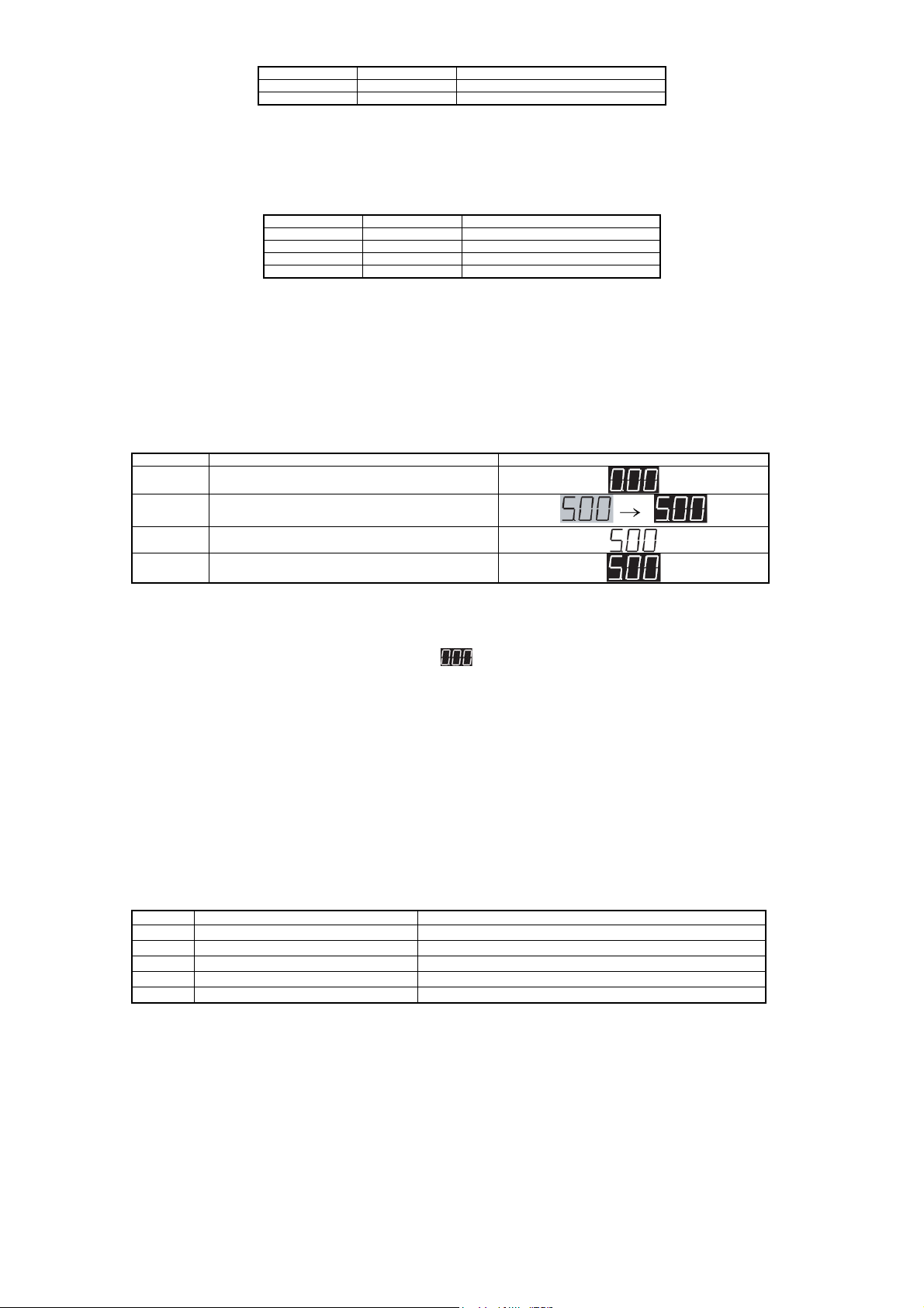
ON OFF The method selected by F1034
OFF ON The method selected by F1035
ON ON The method selected by F1036
Operation command values can be changed using the status of multifunctional input terminals. According to the status of
multifunctional input ROPE or RCOM, the operation commands as shown in the table below can be selected. See F1101 in
Chapter 7-3 for details.
ROPE terminal RCOM terminal Operation command
OFF OFF The method selected by F1101
ON OFF Operation panel
OFF ON Communication
ON ON Terminal block (FR terminal, RR terminal)
6-2-8 Operation confirmation
After setting has been made by following the steps for test run, the operation shall be confirmed as follows.
Once the inverter or motor is in abnormal conditions, please stop operating immediately. See [Chapter 9 Fault Analysis] for
details.
(1) Test run steps
Please refer to the operation methods of operation panel for implementation of 5Hz operation.
Table 6-10 Test run steps
Step Operation Display
①
②
③
④
Connect the power supply after check the wiring
Set the operating frequency to 5Hz according to
the operation panel
Press [DRIVE] key
Press [STOP] key
※ The state where F1101 (operation command selection) is set to 1 (operation by operation panel)
① After power input, check that the frequency “ ” displayed on the operation panel is flashing.
② Set the frequency to a low frequency of about 5Hz through the operation panel. (Check that the set frequency
displayed on LED monitor is flashing)
③ Press [DRIVE] key to start forward running operation.(Check that the set frequency displayed on LED monitor is
flashing)
④ Press [STOP] key to stop operation of the equipment.
(2) Confirmation items during test run
Please confirm the contents listed in the table below
Table 6-11 Confirmation items during test run
Item Result
Motor rotation direction Is it the specified rotation direction?
①
Motor operation 1 Are the acceleration and deceleration smooth?
②
Motor operation 2 Is there any abnormal sound or vibration?
③
Inverter fan operation Is the fan running?
④
Inverter display and others Are the display on operation panel and equipment normal?
⑤
※ When it is confirmed that there is no problem, please increase the set frequency before operation. Similarly, for the
operation with increased frequency, the above confirmation items shall also be checked.
(3) Operation preparation
After confirmation of test run and normal operation confirmation of motor, please implement the connection with the
mechanical system.
① Please set the function codes related to machine action.
② Check the interface matched with peripheral mechanical equipment.
- 39 -

(4) Operation confirmation
Before delivery, various functions of the inverter have been set up as shown in the function code list.
If change of settings of operation command is required, please refer to [5-6 Basic Operation] for implementation.
(5) Operation methods besides commands from operation panel
■ Operation by commands from external signals
① When controlling operation / stop according to external signals, please set the function code F1101 to 2, that is, F1101
= 2.
② When carrying out frequency setting by external potentiometer, 4 - 20mA, 0 - 10V etc., please set the function code
F1002 = 2 - 20.
③ Please refer to [4-6 Connection Diagram of Control Circuit Terminals] for correct use of external signals.
Note 1: If both input signals FR (Forward) and RR (Reverse) are input at the same time, then the inverter will not operate.
And if both signals are simultaneously input during operation, then [Output Frequency Lock] will act. If this is
done during accelerating or decelerating, the change of output frequency will also be locked. And when the
output frequency is locked, the FWD and REV on the operation panel will be lit.
Note 2: If the operation signal is turned off and a signal to drive the motor in the opposite direction from the present
direction of rotation is input before the inverter stops, the inverter operates according to the value of F1001
(motor control mode selection).
·F1001 = 1 (V/f control mode) and F1309 = 0
The inverter operates according to the function code settings when starting and stopping. Consequently, the
change in output frequency around 0 Hz may not follow a straight line, depending on settings such as the
starting frequency. Since DC braking does not work when reversing the direction of rotation, set the DC
braking start frequency low.
·F1001 = 1 (V/f control mode) and F1309 = 1
A process of continuous deceleration to acceleration in the opposite direction, which has nothing to do with the
relevant function codes for starting and stopping.
·F1001 = 2 (Speed sensorless control mode), 3 (speed sensor control mode): Braking excitation or starting
excitation is not applied when switching the direction of rotation. This allows “forward and reverse run” in a
continuous operation.
Note 3: During torque control, the direction of motor rotation depends on the load side, therefore, both FR (Forward run)
and RR (Reverse run) signals are provided with the function of setting ON / OFF of torque control. Because this
function has nothing to do with the direction of rotation, please only use one of FR and RR during torque control.
Forward run Forward run
Reverse run Reverse run
Frequency Frequency
Starting frequency
Starting frequency
[V/f control mode (F1309=1)]
[V/f control mode (F1309=0)] [Speed sensorless or speed sensor control mode]
6-3 Special functions
6-3-1 JOG operation
(1) Short-circuiting the multifunctional terminal JOG with COM1, 2 forms a JOG operation mode.
(2) For JOG operation, please set the F1101 = 2, and then short-circuit the multifunctional terminal FR or RR with COM1,
Time Time
Figure 6-2 External operation command action
- 40 -

2 after short-circuiting the multifunctional terminal JOG with COM1, 2. (JOG operating is active only in operation
by external signal command.)
(3) Use F1021 to set frequency, and F1020 to set the acceleration / deceleration time.
(4) During operation, the JOG signal will not work even if it is input. The JOG signal must be input at the same time or in
advance. Also, during JOG operation, the jog operation will still continue even if the short circuit between JOG and
COM1, 2 is disconnected. (To stop, set the operation signal to OFF.).
(5) In JOG operation mode, the setting of F1102 = 2 (Flying start) becomes inactive, and the setting of F1102 = 1 (Starting
frequency) is active. Other actions shall be made according to settings of corresponding function codes.
(6) Once the JOG operation is started, it will continue until the inverter stops. Therefore, during slowdown of JOG
operation, if acceleration is started again before the inverter stops, it is still in JOG operation regardless of status of
the JOG terminal.
For normal operation after stopping the inverter, please turn the operation command ON (connected) only after the
inverter has fully stopped and the JOG terminal is OFF (disconnected).
ON
short-circuited
ON OFF ON OFF
short-circuited
FR RR
Output
frequency
OFF ON OFF
Operation by external signal
ON OFF
short-circuited JOG operation Normal operation
6-3-2 Hold operation
(1) To use a push-button switch or other momentary contact to control operation, wire the circuit as shown in Figure 6-1
and set the appropriate function codes
(codes related to the multifunctional input terminals and F1101 = 2)
(2) When the external signal terminals are used to operate and stop the inverter, and you do not want the motor to
automatically restart after recovery from a power failure, use the above circuit and set F1108=0.
(3) When operating with the hold function, the inverter does not restart after recovery from the following conditions.
① Recovery from free run stop with MBS multifunctional input terminal
② Recovery from alarm stop with the auto alarm recovery function
③ Recovery from a momentary power failure by the “restart after momentary power failure” function
Figure 6-3 JOG action
DCM1 H D
Stop Reverse Forward
Figure 6-4 Operation signal hold circuit
RR
FR
6-3-3 Notes on free run stop terminal (MBS)
The free run stop terminal is provided for systems in which mechanical braking is used to stop the motor. When setting the motor
- 41 -

to the free run status using this terminal, be sure to turn OFF any operation signal.
If the free run stop signal is released with an operation signal on, the inverter restarts according to normal operating procedure
and the function code settings. Therefore, depending on the free run speed of the motor, an unexpected over current or
overvoltage may occur and result in an alarm stop.
For example: if flying start is not set as the starting method and the free run stop signal is released when the motor is still slowly
rotating, the inverter will restart from the starting frequency or after DC braking depending on the starting method.
- 42 -

t
6-4 Definition of Technical Terms
Output frequency
Operation signal
DC braking signal
Main switching device drive signal
Multifunctional outpu
teriminal operation 1
Multifunctional output
teriminal operation 2
ON
OFF
ON
ON
ON
ON
DC braking DC braking
Standby
Stopped Running Stopped
Figure 6-5 Operation action
Table 6-12 Explanation of Terms
Term Definition
Operation General term describing both “forward run” and “reverse run” implying that the inverter is in operation.
Operation signal
In operation
In constant speed (operation) Condition when the inverter is in operation at the frequency setting value.
Stopped
Standby
DC braking Condition where DC braking is applied when starting and stopping.
Frequency setting value
or set frequency
Output frequency
or
frequency output value
Command frequency
Signal requesting inverter operation, which is input by pressing the [DRIVE] key on the operation panel or using signals input
through multifunctional control input terminals FR and RR.
Condition where the operation signal is being input or a drive signal is being output to the main switching device. In the stop status,
the operation signal is OFF, but the main switching device operates until DC braking, etc. is completed.
Condition where the operation signal is not being input and the drive signal is not being output to the main switching device. Even
when the operation signal input is on, the input to the multifunctional control input terminal MBS disables the drive signal output to
the main switching device.
Condition where the operation signal is being input but there is no output for some reason, for example, while waiting for the start
delay time to expire or when the set frequency is lower than the operation start frequenc y.
Frequency set on F2101-F2116 and F1021.
Frequency value corresponding to an external signal when setting F1002=2-21 and 25-28 with external signals for frequency
setting.
Actual inverter output frequency.
x V/f mode
When the load is stable, the output frequency normally coincides with the frequenc y setting value.
x When used in vector control mode or for slip compensation in V/f mode, even if the load is stable, the output frequency does
not coincide with the frequency setting value but keeps changing.
Frequency value used by the inverter. As a command value frequency, its change in frequency setting value not only depends on
the results of controls such as the acceleration/deceleration function and the current limiting function but also the actual output
frequency. The command frequency normally coincides with the set frequency at the end of acceleration/deceleration.
x V/f mode:
If there is feedback operation such as PID control mode, the command frequency equals the output frequency.
x When used in vector control mode or for slip compensation in V/f mode, the command frequency and the output frequency
may not match in this mode because the synchronous speed specified by the number of motor poles and the command
frequency is used as the speed command.
OFF
ON
OFF
OFF
OFF
- 43 -

7. Function Code
7-1 Representation and Description of Function Codes
By changing the function code, the inverter action can be changed.
Function codes are functionally classified into "function blocks." To change the function code, first select the function block, and
then select the serial number of the function code to be changed.
A function code can be set through operation panel (see sections 5-4 and 5-5), or communication (see section 7-4).
Function Function Block Function Block Name
Basic operation
functions
System-related functions
function
PID function
Motor Parameters
Vector control
Torque control
F10XX
F11XX
F12XX
F13XX
F14XX
F15XX
F16XX
F17XX
F18XX
F19XX
F20XX
F21XX
F22XX
F30XX
F31XX
F32XX
F33XX
F40XX
F41XX
F5XXX
F60XX
F61XX
F81XX
F89XX
Basic functions
Starting • braking function
LED display function
Auxiliary functions
Input function Input/output-related function
Output function
System functions
Protection function
Information function
Energy-saving function Special functions
V/f characteristics
Multi-speed function Scheduled operation
Scheduled operation function
Basic PID1 functions
Basic PID2 functions
Combined function of PID1 and PID2
PID control parameter reading
Serial communication function Communication function
MODBUS communication function
Motor Parameters
Vector control function
Torque control function
PG function Extended functions
Other functions (for factory-adjustment)
7-2 Function Code List
The setting values can not be changed during operation.
※ 1: The representative parameters that are suitable for various models have been input.
- 44 -

Code
No.
Function Name Data Content
Setting
Resolution
Factory
Presets
User
Setting
Value
Basic operation functions
1001 Motor control mode
1002 1st speed frequency
1003 V/f pattern selection 1: Linear pattern
1004 Torque boost
1005 Base voltage 400V series 0: No AVR
1006 Base frequency
1007 Upper frequency limit
1008 Lower frequency limit
1009 Carrier frequency
1010 Acceleration/decelerati
1011 Reference frequency
1012 1st acceleration time 0-6,500 sec.
1013 2nd acceleration time 0-6,500 sec.
1014 3rd acceleration time 0-6,500 sec.
1015 4th acceleration time 0-6,500 sec.
1016 1st deceleration time 0-6,500 sec.
1017 2nd deceleration time 0-6,500 sec.
1018 3rd deceleration time 0-6,500 sec.
1019 4th deceleration time 0-6,500 sec.
1020 JOG
1021 JOG frequency 0-60Hz 0.01Hz 5
1022 1st Start of S-shaped
selection
setting selection
adjustment
on curve
for
acceleration/decelerati
on
acceleration/decelerati
on time
1: V/f control mode
2: Speed control (speed sensorless vector control )
3: Speed control (speed sensor vector control )
4: Torque control (speed sensorless vector control )
5: Torque control (speed sensor vector control )
6: Position control (speed sensor vector control )
10: Auto tuning mode 1
11: Auto tuning mode 2
40: V.f separation control
1:Operation panel
2:External analog VRF1 voltage(0~5V)
3:External analog VRF1 voltage(0~10V or potentiometer)
4:External analog VRF/IRF voltage(0~5V)
5:External analog VRF/IRF voltage(0~10V or potentiometer)
6:Reserved
7:Reserved
8:Reserved
9:External analog VRF/IRFcurrent(4~20mA)
10:Reserved
11:External analog VRF1voltage+VRF/IRFvoltage
12:Reserved
13:Reserved
14:External analog VRF1voltage-VRF/IRFvoltage
15:External analog VRF/IRFvoltage-VRF1voltage
16:Reserved
17:Reserved
18:External analog VRF1 voltage+VRF/IRFcurrent
19:External analog VRF1 voltage-VRF/IRFcurrent
20:External analog VRF1 current-VRF/IRFvoltage
21:Terminal block stepping
22:Communication
25:Pulse train input(Optional function)
:External analog VRF1forward / reverse run operation(0~
26
10V、5V reference)
27:External analog VRF/IRFforward / reverse run operation(0~
10V、5V reference)
28:Reserved
29:Reserved
2: Square-law decreasing pattern (weak)
3: Square-law decreasing pattern (strong)
0-20%(maximum voltage ratio)
0.1~400Hz
5~400Hz
0.05~200Hz
0~130
1: Linear
2: S-shaped
3: Reduction of acceleration/deceleration
1-120Hz 0.01Hz
0-20 sec.
0~200%
50~460V
1 1
1 1
1 1
0.1% 1※
1V
0.01Hz
0.01Hz 60
0.01Hz 0.05
1
1 1
0.1 秒 ※2—1
0.1 秒 ※2—2
0.1 秒 ※2—3
0.1 秒 ※2—4
0.1 秒 ※2—5
0.1 秒 ※2—6
0.1 秒 ※2—7
0.1 秒 ※2—8
0.1 秒
1% 50
※1
※1
※1
※1
0.1
Chapter 7
- 45 -

1023 1st End of S-shaped
1024 Gradient of middle of
1025 1st Start of S-shaped
1026 1st End of S-shaped
1027 Gradient of middle of
1028 2nd Start of S-shaped
1029 2nd End of S-shaped
1030 2nd S-shaped
1031 2nd Start of S-shaped
1032 2nd End of S-shaped
1033 Gradient of middle of
1034
1035
1036
F1037
F1038
1101 Operation command
1102 Starting method 1: Starting frequency
1103 Starting frequency
1104 Operation start
1105 Start delay time 0-5 sec. 0.1 s 0
1106 Start standby time 0-120 sec. 0.1 s 0
1107 Start standby
1108 Restart after
1109 Direction of rotation
acceleration
acceleration
1st S-shaped
Acceleration
deceleration
deceleration
1st S-shaped
Deceleration
acceleration
acceleration
Acceleration Middle
Gradient
Gradient of middle of
2nd t S-shaped
Acceleration
deceleration
deceleration
2nd S-shaped
Deceleration
1st speed frequency
selection A
1st speed frequency
selection B
1st speed frequency
selection C
Terminal block step
size
Frequency held or
reset
selection
frequency
frequency
momentary power
failure
of motor
0~200%
0~100%
0~200%
0~200%
0~100%
0~200%
0~200%
0~100%
0~200%
0~200%
0~100%
1:Operation panel
2:External analog VRF1voltage(0~5V)
3:External analog VRF1voltage(0~10Vor potentiometer)
4:External analog VRF/IRFvoltage(0~5V)
5:External analog VRF/IRFvoltage(0~10Vor potentiometer)
6:Reserved
7:Reserved
8:Reserved
9:External analog VRF/IRFcurrent(4~20mA)
10:Reserved
21:Terminal block stepping
22:Communication
25:Pulse train input
26:External analog VRF1 forward / reverse run operation(0~10V
5V reference)
27:External analog VRF/IRF forward / reverse run operation(0~
10V 5V reference)
28:External analog VRF1 forward / reverse run operation(0
5V reference)
29:Reserved
0.1Hz~10.0Hz
0:Holding frequency
1:Reset when power lost
2:Reset when stoped
1:Operation panel
2:External terminal
3:Communication
2: Flying start
3: Starting frequency after DC braking
0.05~60Hz
0~20Hz
0.05-60Hz 0.01Hz 5
0: Do not restart
1: Restart
2: Compensation for momentary power failure
1: Forward and reverse run
2: Forward run only
3: Reverse run only
~10V
1% 50
1% 0
1% 50
1% 50
1% 0
1% 50
1% 50
1% 0
1% 50
1% 50
1% 0
1 1
1
1
0.1 2.5
1 0
1 1
1 1
0.01Hz 1
0.01Hz 0
1 0
1 1
- 46 -

1110 Direction of rotation
1111 Braking method 1: Deceleration to stop
1112 DC braking start
1113 DC braking time 0.1 -10 sec. 0.1 s 2
1114 DC braking force 1-10 1 5
1115 Duty cycle of brake
1116 Discharge resistor on
1201 Monitor display
1202 State display selection 1: No units (multiple of F1203)
1203 Multiple for no-units
1301 1st jump bottom
1302 1st jump top frequency
1303 2nd jump bottom
1304 2nd jump top
1305 3rd jump bottom
1306 3rd jump top
1307 Auto alarm recovery 0: No auto reset function
1308 Instability elimination
1309 Operation direction
1315 Shortest operation
1316 2nd Upper frequency
1317 3rd Upper frequency
1318 Cooling fan ON/OFF
1319 Functions
1320 Rating selection 1: Mode A (heavy load mode) 150% 1 minute 1 2
of motor
frequency
resistor
signal output
time
selection
display
frequency
frequency
frequency
frequency
frequency
switching in V / f
control mode
time function
limit
limit
control
corresponding to high
altitude areas
1: Forward run
2: Reverse run
2: Deceleration to stop + DC braking
3: Free run stop
0.05-20Hz 0.01Hz 0.5
0: No brake resistor
2-25%ED
98: No discharge resistor protection
(with discharge)
99: External brake unit
0.01 -10.00 sec. 0.01 s 0.1
1: Frequency [Hz]
2: Output current (A)
3: Speed of rotation [rpm]
4: Load factor [%]
5:voltage[V]
6:压力[MPa]
7:No unit display
2: Output voltage [V]
3: DC voltage [V]
4: Active power [kW]
5: Apparent power [kVA]
6: Radiator temperature [ ]℃
7: Command speed [rpm]
8: PID1 feedback value [Hz]
9: PID2 feedback value [Hz]
10: VRF1 analog input value [Hz]
11: VRF/IRF analog input value [Hz]
12: Reserved
13: Output torque [%]
14: Partial excitation current [A]
15: Partial torque current [A]
16: Detecting position [mm]
29: Command frequency [Hz]
30: Command torque [%]
35: Reserved
44:target frequency[HZ]
45:output frequency[HZ]
0-100
(multiple of the output frequency)
0~400 [Hz]
0~400 [Hz]
0~400 [Hz]
0~400 [Hz]
0~400 [Hz]
0~400 [Hz]
1: Auto reset function
0~20
0: Start from the direction opposite to current
direction after a stop
1: Continuous operation
0 -99.99 sec. 0.01 s 0
5-590 [Hz] 0.01 [Hz] 60
5-590 [Hz] 0.01 [Hz] 60
0: ON/OFF control
1: Normally ON
1: 1,000m or below
2: 1,000m-1,500m or below
3: 1,500m-2,000m or below
4: 2,000m-2,500m or below
5:2,500m-3,000m
1 1
1 1
1%ED
1 1
1 1
0.01 倍
0.01 [Hz] 0
0.01 [Hz] 0
0.01 [Hz] 0
0.01 [Hz] 0
0.01 [Hz] 0
0.01 [Hz] 0
1 0
1 0
1 0
1 0
1 1
1※
1
Chapter 7
- 47 -

1401 Bias frequency
1402 Gain frequency
1403 Bias frequency
1404 Gain frequency
1405 Reserved
1406 Reserved
1407 External analog input
1408 External analog input
1409 Reserved
1410 Set frequency gain
1411 Analog input switching
1412 MBS terminal input
1413 ES input terminal
1414
1415
1416
1417
1418
1419
1420
1421
(VRF1)
(VRF1)
(VRF/IRF)
(VRF/IRF)
filter time constant
(VRF1)
filter time constant
(VRF/IRF)
for set
frequency gain
mode
function
Selection of input
terminal DI1
Selection of input
terminal DI2
Selection of input
terminal DI3
Selection of input
terminal DI4
Selection of input
terminal DI5
Selection of input
terminal DI6
Selection of input
terminal DI7
Selection of input
terminal DI8
2: Mode B (light load mode) 120% 1 minute
0~±400 [Hz]
(frequency at 0V)
0~±400 [Hz]
(frequency at 5V or 10V)
0~±400 [Hz]
(frequency at 0V or 4mA)
0~±400 [Hz]
(frequency at 5V or 10V or 20mA)
1-500(set value 1=10ms)
1-500(set value 1=10ms)
0~100
0:No analog input
1:External analog VRF1voltage(0~5V)
2:External analog VRF1voltage(0~10Vor potentiometer)
3:External analog VRF/IRFvoltage(0~5V)
4:External analog VRF/IRFvoltage(0~10Vor potentiometer)
5:Reserved
6:Reserved
7:Reserved
8:External analog VRF/IRFcurrent(4~20mA)
9:Reserved
1: Level triggered
2: Edge triggered
1: NO external thermistor signal
2: NC external thermistor signal
0:Unused
2:RR,
4:3DF
6:ES,
8:AD2,
10:JOG,
12:9DF,
14:RR+JOG,
16:RR+AD2,
18:RR+AD3,
20:RR+2DF,
22:RR+3DF,
24:RR+2DF+3DF,
26:RR+AD2+2DF,
28:RR+AD2+3DF,
29:FR+AD2+2DF+3DF,
:RR+AD2+2DF+3DF,
30
31:FR+AD3+2DF,
33:FR+AD3+3DF,
35:FR+AD3+2DF+3DF,
36:RR+AD3+2DF+3DF,
37:PTR,
40:HD,
46:CCL,
57:P0,
59:FR+RCCL,
65:RR+MBS,
68:2DF+AD3,
70:3DF+AD3,
71:A×10(Optional),
72:A×100(Optional),
75:3MAX,
77:PIDLCK,
84:S2,
86:PIDH,
88:PID1EX
91:IHOLD,
109:RCCL,
115:1DFB,
,
1:FR,
3:2DF,
5:MBS,
7:RST,
9:AD3
11:5DF,
13:FR+JOG,
15:FR+AD2,
17:FR+AD3,
19:FR+2DF,
21:FR+3DF,
23:FR+2DF+3DF,
25:FR+AD2+2DF,
27:FR+AD2+3DF,
32:RR+AD3+2DF,
34:RR+AD3+3DF,
38:T-FCL
39:FR+5DF,
45:CP(Optional),
47:PC,
58:FR+CCL,
64:FR+MBS,
67:2DF+AD2,
69:3DF+AD2,
74:2MAX,
76:VFPID,
83 : For factory
adjustment,
85:PIDL,
87:RPID1,
89:PID2EX,
92:ICLEAR
114:1DFA,
0.1 [Hz] 0
0.1 [Hz] 60
0.1 [Hz] 0
0.1 [Hz] 60
1 10
1 10
1 0
1 0
1 1
1 1
1
1
2
3
4
5
6
7
8
- 48 -

117:ROPE,
119:ROPE+RCOM,
121:1DFB+RCOM,
122:1DFA+1DFB+ROPE+RCOM,
253~255:For factory adjustment,
1422 Reserved
1423 Effective number of
bits for VRF1
detection
1424 Effective number of
bits for VRF/IRF
detection
1425 Reserved
1501 Internal analog output
function1
1502 Internal analog output
coefficient 1
1503 Internal analog output
bias 1
1504 Internal analog output
function2
8~12bit
8~12bit
0:No function
1:Set frequency [Hz]
2:Output frequency [Hz]
3:PID1 feedback value [Hz]
4:PID2 feedback value [Hz]
5:Output current (A)
6:Output voltage [V]
7:DC voltage [V]
8:Radiator temperature [℃]
9:Load factor [%] (electric thermistor integrated value)
10:Load factor [%] (ratio to rated current)
11:VRF1analog input value [V]
12:VRF/IRFanalog input value [V]
13:Reserved
14:Speed [rpm]
15:Active power [kW]
16:Apparent power [kVA]
17:PID1 command value [Hz]
18:PID1 input deviation value [Hz]
19:PID2 command value [Hz]
20:PID2 input deviation value [Hz]
21:For factory adjustment
22:For factory adjustment
23:For factory adjustment
24:External PID1 output value [Hz]
25:External PID2 output value [Hz]
26:For factory adjustment
35:Command frequency [Hz]
36:Command torque [%]
39:Reserved
99:For factory adjustment
0~20
0~±10.0V
0:No function
1:Set frequency (Hz)
2:Output frequency [Hz]
3:PID1 feedback value [Hz]
4:PID2 feedback value [Hz]
5:Output current (A)
6:Output voltage [V]
7:DC voltage [V]
8:Radiator temperature [℃]
9:Load factor [%] (electric thermistor integrated value)
10:Load factor [%] (ratio to rated current)
11:VRF1analog input value [V]
12:VRF/IRFanalog input value [V]
13:Reserved
14:Speed [rpm]
15:Active power [kW]
16:Apparent power [kVA]
17:PID1 command value [Hz]
18:PID1 input deviation value [Hz]
19:PID2 command value [Hz]
20:PID2 input deviation value [Hz]
21:For factory adjustment
22:For factory adjustment
23:For factory adjustment
116:1DFA+1DFB,
118:RCOM,
120:1DFA+ROPE,
1bit 12
1bit 12
1 0
0.01 1
0.1V 0
1 0
Chapter 7
- 49 -

24:External PID1 output value [Hz]
25:External PID2 output value [Hz]
26:For factory adjustment
35:Command frequency [Hz]
36:Command torque [%]
39:Reserved
99:For factory adjustment
1505 Internal analog output
1506 Internal analog output
1507 Approach frequency 0~400Hz 0.01Hz 10
1508 Frequency matching
1509
1510
1511
1512 Counter output
1513 Relay 1 contact output
coefficient 2
bias 2
range
Selection of output
terminal DO1
Selection of output
terminal DO2
Selection of output
terminal DO3
multiple
selection
0~20 0.01 1
0~±10.0V 0.1V 0
0~10Hz 0.01Hz 0
0:Unused,
1:In operation 1
2:Undervoltage,
3:End of simple scheduled operation,
4:In operation 2,
5:Frequency matching (1st speed frequency),
6:Frequency matching (1st to 16th speed frequencies),
7:Frequency approach,
8:Overload alarm level setting signal (the value of F1704),
9:Electric thermistor pre-alarm signal ,
10:Radiator overheat pre-alarm signal,
13:Excitation and DC braking signals,
14:Lower frequency limit matching signal,
15:Upper frequency limit matching signal,
16:Servo on ready signal (Optional),
17:Zero servo completion signal (Optional),
18:FRsignal, 19:RRsignal,
20:2DFsignal, 21:3DFsignal,
:5DFsignal, 23:9DFsignal,
22
24:AD2signal, 25:AD3signal,
26:JOGsignal, 27:MBSsignal,
28:ESsignal, 29:RSTsignal,
31:Positioning completion signal(Optional),
32:Discharge resistor on signal,
34: Frequency counter (output frequency),
35:Frequency counter (command frequency),
36:Overload alarm level setting signal,
42:Torque matching signal,
43:Low speed detection signal
47:Motor speed counter
48:Forward run detection signal
49:Reverse run detection signal
1~100 倍 1倍 1
0:Alarm contact,
1:In operation 1,
2:Undervoltage,
3:End of simple scheduled operation,
4:In operation 2,
5:Frequency matching (1st speed frequency),
6:Frequency matching (1st to 16th speed frequencies),
7:Frequency approach,
8:Overload alarm level setting signal (the value of F1704),
9:Electric thermistor pre-alarm signal ,
10:Radiator overheat pre-alarm signal,
13:Excitation and DC braking signals,
14:Lower frequency limit matching signal,
15:Upper frequency limit matching signal,
16:Servo on ready signal ,
17:Zero servo completion signal ,
18:FRsignal, 19:RRsignal,
20:2DFsignal, 21:3DFsignal,
22:5DFsignal, 23:9DFsignal,
24:AD2signal, 25:AD3signal,
26:JOGsignal, 27:MBSsignal,
28:ESsignal, 29:RSTsignal,
31:Positioning completion signal,
32:Discharge resistor on signal,
36:Overload alarm level setting signal,
42:Torque matching signal,
1 1
5
8
1 0
- 50 -

43: Low speed detection signal
48:Forward run detection signal
49:Reverse run detection signal
1514 Relay 1 contact output
selection
1515 Reserved
1516 Torque matching level
1517 Torque matching range
1518 Low speed matching
level
1519 Low speed matching
range
1520 Reserved
1521 Reserved
0:Alarm contact,
1:In operation 1,
2:Undervoltage,
3:End of simple scheduled operation,
4:In operation 2,
5:Frequency matching (1st speed frequency),
6:Frequency matching (1st to 16th speed frequencies),
7:Frequency approach,
8:Overload alarm level setting signal (the value of F1704),
9:Electric thermistor pre-alarm signal ,
10:Radiator overheat pre-alarm signal,
13:Excitation and DC braking signals,
14:Lower frequency limit matching signal,
15:Upper frequency limit matching signal,
16:Servo on ready signal ,
17:Zero servo completion signal ,
18:FRsignal, 19:RRsignal,
20:2DFsignal, 21:3DFsignal,
22:5DFsignal, 23:9DFsignal,
24:AD2signal, 25:
26:JOGsignal, 27:MBSsignal,
28:ESsignal, 29:RSTsignal,
31:Positioning completion signal,
32:Discharge resistor on signal,
36:Overload alarm level setting signal,
42:Torque matching signal,
43: Low speed detection signal
48:Forward run detection signal
49:Reverse run detection signal
0~±200%
0~50%
0~2000rpm
0~100rpm
AD3signal,
1 0
0.1 % 100
0.1 % 25
1rpm 100
1rpm 10
System-related functions
1601 Copy function
1602 Changed code display
function
1603 Function lock
1604 Data initialization
1605 Reserved
1606 Reserved
1607 Reserved
1701 Output current limiting
function
B MODEL
1702 Electric thermal setting
1703 Output current limiting
at constant speed
0:No function
1:Transfer the current code data to the operation
panel
2:Transfer the contents stored by operation panel to the inverter
(Excluding motor parameters measured )
3:Transfer the contents stored by operation panel to the inverter
(Including motor parameters measured )
0:No function
1:Display differences from factory preset
2:Display differences from user’s initial value
0:Code data changeable(No lock function)
1:Code data unchangeable (except F1603)
2:Code data (except frequency setting-related) unchangeable
(except F1603, F1021, F2101 — F2116)
3:Code data unchangeable (except F1603 and function codes
using communication)
0:No function
1:Initialize factory presets
2:Invalid parameter by auto tuning
3:Initialize user’s data
99:Set user’s initial value
A MODEL
0:No function
20~105%
0:No function
0:No function
50~200%
0:No function
50~150%
1 0
1 0
1 0
1 0
1% 150
120
1% 100
1 0
Chapter 7
- 51 -

1:Yes, V/F mode, (Currently selected
acceleration/deceleration time)
2:Yes, V/F mode, (1st acceleration/deceleration time)
3:Yes, V/F mode,
(2nd acceleration/deceleration time)
4:Yes, V/F mode,
(3rd acceleration/deceleration time)
5:Yes, V/F mode, (4th acceleration/deceleration time)
6:Yes, V/f mode and speed vector control mode
(1st acceleration/deceleration time)
7:Yes, V/f mode and speed vector control mode
(2nd acceleration/deceleration time)
8:Yes, V/f mode and speed vector control mode
(3rd acceleration/deceleration time)
9:Yes, V/f mode and speed vector control mode
(4th acceleration/deceleration time)
setting value
1705 Motor type
1706 Function to switch
between “OV” and
“LV” alarms when
stopped
1707 Missing Phase
detection function
1708 Overvoltage stalling
prevention function
1709 Feedback signal
disconnection
detection time
1710 Carrier frequency
variable by lowering
temperature
(Active when only
mode A is selected)
1801 Inverter host software
version query
1802 Memory Version query Read only Version
1803 Operation panel
software version query
1804 Operation time display Read only 1 hour ---
1805 Reading alarm data
1806 Alarm status
confirmation1
1807 Alarm status
confirmation2
1808 Alarm status
confirmation3
1809 Alarm status
confirmation4
1810 Alarm status
confirmation5
A MODEL
B MODEL
1:General-purpose motor
2:Exclusive motor for the inverter
0:“OV” enabled, “LV” disabled when stopped
1:“OV” disabled, “LV” enabled when stopped
2:“OV” disabled, “LV” disabled when stopped
3:“OV” enabled, “LV” enabled when stopped
0:No input phase loss, no output phase loss
1:Input phase loss, no output phase loss
2:No input phase loss, output phase loss
3:Input phase loss, output phase loss
0:No overvoltage stalling prevention function.
1:Overvoltage stalling prevention function.
0:Only warning
0.01 -119.99 sec.
120: No detection
0:Disabled
1:Enabled
Read only Version
Read only Version
0:No function
1:Read start
9:Record erase
Read only --- ---
Read only --- ---
Read only --- ---
Read only --- ---
Read only --- ---
20~200%
20~150%
1%
1 1
1 0
1 3
1 1
0.01 s 5
1 0
1 0
150 1704 Overload alarm level
120
Special functions
1901 Energy-saving mode
1902 Simple energy saving
1903 Simple energy saving
2001
2002 V·f separation
2003 Arbitrary V/f pattern
2004 Arbitrary V/f pattern
2005 Arbitrary V/f pattern
selection
rate
time
V•f separation
function selection
command voltage
intermediate voltage 1
intermediate voltage 2
0:No function
1:Simple energy-saving mode (V/f mode)
2:Auto energy-saving mode
0~50%
0~65000s
1:V · f proportional separation
2:Complete separation
0:Disabled (command is given by VIF1)
0.01~40.95V
0~460V
0~460V
0.05~400Hz
1 0
1% 0
1s 10
1 1
0.01V 0
1V 0
1V 0
0.01Hz 20
- 52 -

intermediate frequency
1
2006 Arbitrary V/f pattern
intermediate frequency
2
2007 Automatic torque boost
selection
2008 Slip compensation
response time constant
2009 Slip compensation
multiple
Graph operation function
2101 1st speed frequency
2102 2nd speed frequency
2103 3rd speed frequency
2104 4th speed frequency
2105 5th speed frequency
2106 6th speed frequency
2107 7th speed frequency
2108 8th speed frequency
2109 9th speed frequency
2110 10th speed frequency
2111 11th speed frequency
2112 12th speed frequency
2113 13th speed frequency
2114 14th speed frequency
2115 15th speed frequency
2116 16th speed frequency
2201 Selection of Scheduled
operation
2202 Simple scheduled
operation repetitions
2203 Operation timer T1
2204 Operation timer T2
2205 Operation timer T3
2206 Operation timer T4
2207 Operation timer T5
2208 Operation timer T6
2209 Operation timer T7
2210 Operation timer T8
2211 Operation timer T9
2212 Operation timer T10
2213 Operation timer T11
2214 Operation timer T12
2215 Operation timer T13
2216 Operation timer T14
2217 Operation timer T15
2218 Operation stop time T0
2219 Midway stop
deceleration time
2220 Midway start
acceleration time
2221 Forward/reverse and
acceleration/decelerati
on in T1
2222 Forward/reverse and
acceleration/decelerati
on in T2
2223 Forward/reverse and
acceleration/decelerati
on in T3
2224 Forward/reverse and
acceleration/decelerati
on in T4
0.05~400Hz
0:No automatic torque boost
1:Voltage compensation function
2:Slip frequency compensation
0~1000(set value 1=10ms)
0.01~2
0~400Hz
0~400Hz
0~400Hz
0~400Hz
0~400Hz
0~400Hz
0~400Hz
0~400Hz
0~400Hz
0~400Hz
0~400Hz
0~400Hz
0~400Hz
0~400Hz
0~400Hz
0~400Hz
0:Normal operation
1:Simple scheduled operation
2:Disturbed operation
0:Continuous
1~250:Repetition count
0~65000sec.
0~65000sec.
0~65000sec.
0~65000sec.
0~65000sec.
0~65000sec.
0~65000sec.
0~65000sec.
0~65000sec.
0~65000sec.
0~65000sec.
0~65000sec.
0~65000sec.
0~65000sec.
0~65000sec.
0~65000sec.
1:1st deceleration time (value of F1016)
2:2nd deceleration time (value of F1017)
3:3rd deceleration time (value of F1018)
4:4th deceleration time (value of F1019)
1:1st acceleration time (value of F1012)
2:2nd acceleration time (value of F1013))
3:3rd acceleration time (value of F1014)
4:4th acceleration time (value of F1015)
X Y
X…1:Forward run
2:Reverse run
Y…1~4:Acceleration/deceleration time specified
0.01Hz 40
1 0
1 10
0.01 1
0.01Hz 0
0.01Hz 10
0.01Hz 20
0.01Hz 30
0.01Hz 40
0.01Hz 50
0.01Hz 60
0.01Hz 0
0.01Hz 0
0.01Hz 5
0.01Hz 15
0.01Hz 25
0.01Hz 35
0.01Hz 45
0.01Hz 55
0.01Hz 0
1 0
1 1
1s 10
1s 10
1s 10
1s 10
1s 10
1s 10
1s 10
1s 10
1s 10
1s 10
1s 10
1s 10
1s 10
1s 10
1s 10
1s 10
1 1
1 1
--- 11
--- 11
--- 11
--- 11
Chapter 7
- 53 -

2225 Forward/reverse and
2226 Forward/reverse and
2227 Forward/reverse and
2228 Forward/reverse and
2229 Forward/reverse and
2230 Forward/reverse and
2231 Forward/reverse and
2232 Forward/reverse and
2233 Forward/reverse and
2234 Forward/reverse and
2235 Forward/reverse and
2236 Disturb modulation
2237 Disturb modulation
acceleration/decelerati
on in T5
acceleration/decelerati
on in T6
acceleration/decelerati
on in T7
acceleration/decelerati
on in T8
acceleration/decelerati
on in T9
acceleration/decelerati
on in T10
acceleration/decelerati
on in T11
acceleration/decelerati
on in T12
acceleration/decelerati
on in T13
acceleration/decelerati
on in T14
acceleration/decelerati
on in T15
analog input switching
rate
PID function
3001
3002 PID1 feedback input
3003 PID1 control
PID1 command value
input switching
switching
proportional gain
0:No analog input
1:External analog VRF1voltage(0~5V)
2:External analog VRF1voltage(0~10Vor potentiometer)
3:External analog VRF/IRFvoltage(0~5V)
4:External analog VRF/IRFvoltage(0~10Vor potentiometer)
5:Reserved
6:Reserved
7:Reserved
8:External analog VRF/IRFcurrent(4~20mA)
9:Reserved
0~50%
1:Frequency
2:External analog VRF1voltage(0~5V)
3:External analog VRF1voltage(0~10Vor potentiometer)
4:External analog VRF/IRFvoltage(0~5V)
5:External analog VRF/IRFvoltage(0~10Vor potentiometer)
6:Reserved
7:Reserved
8:Reserved
9:External analog VRF/IRFcurrent(4~20mA)
10:Reserved
11:Function code setting(F3017)
98:Reserved
99:Pulse train input(Optional function)
0:No input
1:External analog VRF1voltage(0~5V)
2:External analog VRF1voltage(0~10Vor potentiometer)
3:External analog VRF/IRFvoltage(0~5V)
4:External analog VRF/IRFvoltage(0~10Vor potentiometer)
5:Reserved
6:Reserved
7:Reserved
8:External analog VRF/IRFcurrent(4~20mA)
9:Reserved
10:Communication mode
98:Reserved
99:PG feedback PID
0~100
(Optional function)
--- 21
--- 21
--- 21
--- 11
--- 11
--- 11
--- 11
--- 21
--- 21
--- 21
--- 21
1 0
1% 0
1 1
1 0
0.01 0.1
- 54 -

3004 PID1 control integral
3005 PID1 control
3006
3007
3008 Indirect PID1 input
3009 PID1 deviation limit
3010 PID1 output limit value
3011 PID1 operation
3012 PID1 gain polarity
3013 PID1 command value
3014 PID1 feedback value
3015 PID1 control
3016 PID1 control integral
3017 PID1 control command
3018
3019
3101 PID2 command value
3102 PID2 feedback input
3103 PID2 control
3104 PID2 control integral
3105 PID2 control
3106 PID2 control integral
time
differential time
PID1 control integral
separation judgment
value
PID1 feedback signal
input filter
time constant
reference
value
polarity switching
switching
gain
gain
proportional gain
(negative:F3012=2)
time
(negative:F3012=2)
value
PID1 control feedback
value (communication
function)
Frequency
corresponding to PID1
control maximum
command value
input switching
switching
proportional gain
time
differential time
separation judgment
0.01~100s
0~100s
5~100%(upper frequency limit reference)
1~500(set value 1=10ms)
5~100% (target value reference)
0:No limit
1~100% (upper frequency limit reference)
0:No limit
1~100% (upper frequency limit reference)
1:Command value – feedback value
2:Feedback value – command value
1:The positive or negative deviation indicates
the same gain
2:The positive or negative deviation indicates
different gains
0~50
0~50
0~100
0.01~100s
0~4000
0~4000
0~400Hz
1:Frequency
2:External analog VRF1voltage(0~5V)
3:External analog VRF1voltage(0~10Vor potentiometer)
4:External analog VRF/IRFvoltage(0~5V)
5:External analog VRF/IRFvoltage(0~10Vor potentiometer)
6:Reserved
7:Reserved
8:Reserved
9:External analog VRF/IRFcurrent(4~20mA)
10:Reserved
11:Function code setting(F3117)
98:Reserved
99:Pulse train input(Optional function)
0:No input
1:External analog VRF1voltage(0~5V)
2:External analog VRF1voltage(0~10Vor potentiometer)
3:External analog VRF/IRFvoltage(0~5V)
4:External analog VRF/IRFvoltage(0~10Vor potentiometer)
5:Reserved
6:Reserved
7:Reserved
8:External analog VRF/IRFcurrent(4~20mA)
9:Reserved
10:Communication mode
98:Reserved
99:PG feedback PID (option)
0~100
0.01~100s
0~100s
5~100%(upper frequency limit reference)
0.01s 0.1
0.01s 0
0.1% 20
1 10
0.1% 20
0.1% 100
0.1% 100
1 1
1 1
0.01 1
0.01 1
0.01 0.1
0.01s 0.1
0.1 0
0.1 0
0.01Hz 60
1 0
1 0
0.01 0.1
0.01s 0.1
0.01s 0
0.1% 20
Chapter 7
- 55 -

value
3107
3108 Indirect PID2 input
3109 PID2 deviation limit
3110 PID2 utput limit value
3111 PID2 operation
3112 PID2 gain polarity
3113 PID2 command value
3114 PID2 feedback value
3115 PID2 control
3116 PID2 control integral
3117 PID2 control command
3118
3119
3123 PID start mode
3124 PID end mode
3125 PID end setting value
3127 For factory adjustment
3201 PID control action
3202 For factory adjustment
3203 External PID control
3204 External PID operation
3205 PID constitution
3206 Command value
3207 PID1/PID2 switching
3301 Reading PID1
3302 Reading PID1
3303 Reading PID1 input
3304 Reading PID1 output
3305 Reading PID2
PID2 feedback signal
input filter time
constant
reference
value
polarity switching
switching
gain
gain
proportional gain
(negative:F3012=2)
time
(negative:F3012=2)
value
PID2 control feedback
value (communication
function)
Frequency
corresponding to PID2
control maximum
command value
selection
selection
selection
selection
mode selection
selection
addition
calculation PID control
gain
time
command value
feedback value
deviation
value
command value
1~500(set value 1=10ms)
5~100%(target value reference)
0:No limit
1~100%(upper frequency limit reference)
0:No limit
1~100%(upper frequency limit reference)
1:Command value – feedback value
2:Feedback value – command value
1:The plus or minus deviation indicates the same gain
2:The plus or minus deviation indicates different gains
0~50
0~50
0~100
0.01~100s
0~4000
0~4000
0~400Hz
1:Direct input mode
2:Condition input mode
1:Direct end mode
2:Condition end mode
1~100%(upper frequency limit standard)
0:Open loop control
1:PID1 control
2:PID2 control
3:For factory adjustment
4:External terminal switching PID control
5:Timing switch PID control
0:No external PID control
1:External control PID1
2:External control PID2
3:For factory adjustment
4:external controls PID1 and PID2
5:For factory adjustment
6:For factory adjustment
1:Operation interlocked with inverter operation
2:PID output after power input
3:PID output controlled by external terminals
0:Without command value addition calculation
1:With command value addition calculation
0.01~100
0.1~6000 minutes
Read only 1 ---
Read only 1 ---
Read only 1 ---
Read only 1 ---
Read only 1 ---
1 10
0.1% 20
0.1% 100
0.1% 100
1 1
1 1
0.01 1
0.01 1
0.01 0.1
0.01s 0.1
0.1 0
0.1 0
0.01Hz 60
1 1
1 1
0.1% 20
1 0
1 0
1 1
1 0
0.01 1
0.1 minute 0.1
- 56 -

3306 Reading PID2
feedback value
3307 Reading PID2 input
deviation
3308 Reading PID2 output
value
3309 For factory adjustment
3310 For factory adjustment
3311 For factory adjustment
3312 For factory adjustment
Read only 1 ---
Read only 1 ---
Read only 1 ---
Communication function
4001 Message checksum
4003 Pull-up/down function
4004 Communication
4005 Serial communication
4006 Inverter No.
4007 Communication speed
4008 Parity bit
4009 Stop bit
4010 End bit
4011 Inverter’s response to
4101 ModBus
4102 ModBus
4103
response time
function
specified commands
communication
timeout setting
communication
timeout action
Modbus register
address switching
0:No
1:Yes
0:No
1:Yes
10~4000ms
0:No function
1:Dedicated protocol communication function
2:ModBus communication function
0~254;for ModBus only
(1~32;for RS485 communication)
1:1200bps
2:2400bps
3:4800bps
4:9600bps
5:19200bps
6:38400bps
7:57600bps
0:No
1:Odd
2:Even
1:1 bit
2:2 bits
0:CR+LF
1:CR
0:Sent
1:Not sent (Error response sent)
2:Not sent (No error response sent)
0:No function
0.01~600s
0:Keep the status
1:Stop alarm
1:register number A
2:register number B
1 1
1 1
1ms 10
1 1
1 1
1 4
1 1
1 1
1 0
1 0
0.01s 0
1 0
1 1
Motor Parameters
5001 Motor poles
voltage· capacity
5002 Motor current rating
5003 Motor frequency rating
5004 Motor speed rating
5005 Motor insulation type
5006 The motor’s rated
voltage during auto
tuning of motor
parameters
5007 Rated motor slip ratio
5008 The setting of motor
parameter auto tuning
range
X Y ZZZ
X:Poles
Y:Rated voltage
Z:Motor capacity
0.1~999.9A
About 30 — 110% of the inverter current rating
10~400Hz
0~24000 rpm
1:Type A
2:Type E
3:Type B
4:Type F
5:Type H
0:The voltage selected by F5001
100~460V
0~50%
0:No range
50~300%
55kW or below
75kW or or above
0.001~65Ω
0.01~650mΩ
—
0.1A
1Hz
1rpm
1
1V 0
0.1% 2
0.1% 200
0.001Ω 5009 Motor stator resistance
0.01mΩ
※ 1
※ 1
※ 1
※ 1
※1
※1
Chapter 7
- 57 -

5010 Motor rotator
5014 Motor excitation
5015 Motor’s moment of
5016 Load’s inertia moment
resistance
inductance
inductance
inductance
current
inertia
ratio
Vector control
6001 Torque limiter (power
6002 Torque limiter analog
6003 Torque limiter
6004 Torque limiter analog
6005 Multiple for starting
6006 Starting excitation
6007 Multiple for braking
6008 Braking excitation
6009 Current control gain
6010 Speed control ASR
6011 Speed control ASR
6012 Speed detection filter
6013 Torque detection filter
6014 Motor vibration
6015 Lower frequency limit
6016 Upper frequency limit
6017 Starting torque
6018 Starting torque
6019 Variable 2nd gain for
running)
input function
power running)
(
(regeneration)
input function
(regeneration)
excitation current
time
excitation current
time
compensation
proportional gain
integral time
cut-off frequency
cut-off frequency
reduction rate
for motor vibration
reduction function
for motor vibration
reduction function
duration time
speed control
55kW or below
75kW or above
55kW or below
75kW or above
55kW or below
75kW or above
55kW or below
75kW or above
0.01~650A
0~65kgm
1~200
A MODEL
B MODEL
0:F6001
1:External analog VRF1voltage(0~5V)
2:External analog VRF1voltage(0~10Vor potentiometer)
3:External analog VRF/IRFvoltage(0~5V)
4:External analog VRF/IRFvoltage(0~10Vor potentiometer)
5:Reserved
6:Reserved
7:Reserved
8:External analog VRF/IRFcurrent(4~20mA)
9:Reserved
A MODEL
B MODEL
0:F6003
1:External analog VRF1voltage(0~5V)
2:External analog VRF1voltage(0~10Vor potentiometer)
3:External analog VRF/IRFvoltage(0~5V)
4:External analog VRF/IRFvoltage(0~10Vor potentiometer)
5:Reserved
6:Reserved
7:Reserved
8:External analog VRF/IRFcurrent(4~20mA)
9:Reserved
0.1—2 (for applicable motor) 0.01 1
0:No starting excitation
0.1~10s
0.1—2 (for applicable motor) 0.01 1
0:No braking excitation
0.1~10s
0.5~1.5
0.01~150%
0~20s
0:No function
0.01~400Hz
0:No function
0.1~4000Hz
0:No function
1:75%
2:50%
3:25%
0~240Hz
0~240Hz
0~100%
0~6500s
0:No variable gain function
0.01~150%
2
0~200%
0~150%
0.001~65Ω
0.01~650mΩ
0.1~6000mH
0.01~600mH
0.1~6000mH
0.01~600mH
0.1~6000mH
0.01~600mH
0~200%
0~150% 0.1%
0.001Ω
0.01mΩ
0.1mH 5011 Motor stator
0.01mH
0.1mH 5012 Motor rotator
0.01mH
0.1mH 5013 Motor’s mutual
0.01mH
0.01A
0.001kgm
0.01 1
0.1%
1 0
0.1% 100
1 0
0.1s
0.1s 1
0.01 1
0.01%
0.001s
0.01Hz 0
0.1Hz 0
1 0
0.01Hz 0
0.01Hz 0
0.1% 30
0.1s 1
0.01% 15
※1
※1
※1
※1
※1
2
※1
150
120
※1
※1
※1
- 58 -

6020 Frequency bottom of
variable gain for
speed control
6021 Frequency top of
variable gain for
speed control
0~240Hz
0~240Hz
0.01Hz 10
0.01Hz 30
Torque control
6101 Torque command
selection
6102 Torque command
6103 Positive upper value of
Torque command
6104 Positive lower value of
torque command
6105 Negative upper value
of torque command
6106 Negative lower value
of torque command
6107 Bias torque command
(VRF1)
6108 Gain torque command
(VRF1)
6109 Bias torque command
(VRF/IRF)
6110 Gain torque command
(VRF/IRF)
6111 Reserved
6112 Reserved
6113 Torque characteristics
selection in constant
power zone
6114 Speed limit selection
6115 Speed limit value in
torque control
(Forward run side)
6116 Speed limit value in
torque control
(Reverse run side)
6117 Torque control
proportional gain
6118 Torque control integral
time
6119 Lower torque limiting
value in speed limiting
1:Operation panel
2:External analog VRF1voltage(0~5V)
3:External analog VRF1voltage(0~10Vor potentiometer)
4:External analog VRF/IRFvoltage(0~5V)
5:External analog VRF/IRFvoltage(0~10Vor potentiometer)
6:Reserved
7:Reserved
8:Reserved
9:External analog VRF/IRFcurrent(4~20mA)
10:Reserved
A MODEL
B MODEL
20.0~200.0%
0~20.0%
20.0~200.0%
0~20.0%
0~±200.0%(torque command of 0V)
0~±200.0%(torque command of 5V or 10V)
0~±200.0%(torque command of 5V or 10V)
0~±200.0%(torque command of 5V or 10V or 20mA)
0:Constant torque constant power limit
1:Constant torque limit
0:Speed limit under 1st speed frequency command
1:Speed limit in function codes
0~8000rpm
0~8000rpm
0.01~150%
0~500ms
0~100%
0~±200.0%
0~±150.0%
1 1
0.1% 10
0.1% 100
0.1% 5
0.1% 100
0.1% 5
0.1% 0
0.1% 100
0.1% 0
0.1% 100
1 0
1 1
1rpm 1800
1rpm 1800
0.01%
0.1ms 50
0.1% 30
※ 1
Extended functions
8007
8018
8019
8022
8023
8024
8025
8026
8027
PG sensorfunction(need Optional)
Select water supply
optional modes
Sleep wake up ratio K
Sleep wake up decision
time TP
Pressure
command(Operation
panel) Pref
Analog feedback: offset
pressure Pb
Analog feedback:
pressure gain Pg
Pressure upper limit PH
ratio
Pressure lower limit PL
ratio
The slope of pressure
acceleration/deceleratio
n
0~15
30~95
0.1~10.0 min
0.000~9.999 MPa
-9.999~9.999 MPa
-9.999~9.999 MPa
0.01~100.00%
0.01~100.00%
0.01~0.4
1 0
1% 50%
0.1 5
0.001 0.000
0.001 0.000
0.001 0.000
0.001 100.00
0.01 0.00
0.01 0.100
Chapter 7
- 59 -

8101 Point to Point control
8102 Effective number of
8103 Simple Backlash
8104 Command pulse
8105 Command pulse logic
8106 PG pulse output
8107 Deviation counter
8108 PG pulse
8109 PG output formation
8110 Position control gain
8111 Positioning
8112 Error level limit
8113 Quick
8114 Number of pulses
8115 Point to point control
8116 Electric gear ratio
8117 Electric gear A data
8118 Electric gear B data
8119 Zero-servo control
8120 Zero speed
8121 Zero speed servo
8122 Number of PG pulses
8123 For factory adjustment
8124 For factory adjustment
8125 PG pulse A-B polarity
8126 Speed control ASR
8127
8128
8129
8999 For factory adjustment
position limiter
bits for Point to Point
control position
(Unit=mm)
calibration
format
(Optional function)
(Optional function)
divisor
(Optional function)
clear mode
multiplication value
(Optional function)
selection (Optional
function)
completion width
acceleration/decelerati
on for position control
within 1 mm
command
function selection
(Optional function)
(optional function)
(optional function)
function selection
complete width
(Optional function)
reversal
(Optional function)
proportional gain in
zero-servo
Reserved
Reserved
Reserved
The setting values can not be changed during operation.
1~32767mm
1:Integer
2:1 digit after decimal point is effective
3:2 digits after decimal point are effective
0~±5000 pulses
1:Forward / reverse run pulse train
2:Sign pulse train
3:2-phase pulse train
1:Positive logic
2:Negative logic
1:1/1
2:1/2
3:1/4
4:1/8
5:1/16
1:Level operation
2:Rising edge operation
1:×1
2:×2
3:×4
1:Corresponding to open collector PG(Optional)
2:Corresponding to open collector PG(Optional)
3:Corresponding to bus driver PG(Optional)
0.1~50 rad/s
0~32767 pulses
0-1,000(set value 1=100 pulses)
0:Disabled
1:Enabled
0:Pulse is specified with F8115
1~32767 pulses
0:No function
1~32767 pulses
0.01~32767mm(※3)
0:Inactive
1:Active
1~100
1~100
0:Inactive
1:Active
2:Switching on external terminal (P0) zero-servo
1~3000rpm
5~10000 pulses
50~2048 pulses
0:Inactive
1:Polarity reversal
0:Act according to the set value of F6010
0.01~150%
1mm 32767
1 1
1 pulse 0
1 1
1 1
1 1
1 2
1 3
1 1
0.1rad/s 1
1 pulse 100
1 100
1 1
1 pulse 0
(※3)
1 0
1 1
1 1
1 0
1rpm 30
1 pulse 10
1 pulse 1000
1 0
0.01% 15
0
※1:The representative parameters that are suitable for various models have been input.
The following values have been input from※2-1to ※2-8 in various models of inverters.
- 60 -

Model
S06-4A005~4A025-*4
S06-4A032~4A038-*4
S06-4A049~4A152-*4
※2-1
F1012
5 10 15 20 5 10 15 20
15 30 45 60 15 30 45 60
30 60 90 120 30 60 90 120
※2-2
F1013
※2-3
F1014
※2-4
F1015
※2-5
F1016
※2-6
F1017
※3:
Data Content Data content and setting resolutions change with function codes. See 7-3 Description of Functions for details.
※2-7
F1018
※2-8
F1019
Chapter 7
- 61 -

7-3 Description of Functions
7-3-1 Basic functions
Basic functions
F1001
A function for selecting motor control mode.
Code No. Function Name Data Content Setting Resolution Factory
F1001 Motor control mode
z F1001=1:the motor is controlled by the V / f graph set in V / f mode.
z F1001=2:Speed control mode(speed sensorless vector control),F1001=3:Speed control mode(speed sensor vector control)。
Speed control is a control mode that will maintain a constant speed regardless of what the load condition is. And, it is a control
mode which allows the motor to generate high torque from the low-frequency field. In speed control, you can select speed
sensorless vector control (F1001 = 2) or speed sensor vector control (F1001 = 3). The figure below shows the setting flow through
which the vector speed control is realized.
Motor control mode selection
selection
1:V/f control mode
2:Speed control(speed sensorless vector control)
3:Speed control(speed sensor vector control)
4:Torque control(speed sensorless vector control)
5:Torque control(speed sensor vector control)
6:Position control(speed sensor vector control)
10:Motor parameter auto tuning mode 1
11:Motor parameter auto tuning mode 2
40:V·f separation control
1 1
Presets
Speed sensorless vector control
(F1001=2)
Setting motor parameters
(F5001)
Motor parameter auto
tuning
(F1001=10 or 11)
Setting of torque limiter
Setting of starting o braking
excitation
Setting of speed control gain
Test run
Speed sensor vector control
(F1001=3)
Setting motor parameters
(F5001)
Basic setting of PG sensor
F8100-related
(Related function codes)
y To carry out speed control mode selection, please refer to description of relevant parts of function code F6000.
y To carry out speed sensor vector control mode selection, please refer to description of relevant parts of function code F8100 for
basic setting of PG sensor.
Notes on use of speed control mode:
Note 1: When setting the control mode of speed sensorless vector control, the following conditions must be met.
1. One inverter to one motor.
2 .The motor must be a Sanken designated 2-pole, 4-pole or 6-pole 3-phase induction motor or a similar motor.
3 .The motor drive capacity must be equal to that of the standard motor suitable for the inverter rating or one rank below.
4 .The wiring length between the inverter and the motor shall be less than 30 m. If the wiring length exceeds 30 m, conduct
auto tuning of the motor parameters in advance using the auto tuning mode 2.
And, for vector control, the maximum wiring length shall be controlled within 100m.
- 62 -

Note 2: F5001 does not apply to the setting of and in Note 1, please s②③ et it correctly according to the above. And, the inverter
action and control characteristics cannot be guaranteed where the F5001's setting does not match ratings of the connected
motor.
Note 3: In the speed sensorless vector control mode, motor parameters, control frequency and voltage are used to drive the motor,
therefore control characteristics depend on motor parameters, and the best performance may not be achieved depending on
the motor. If motor characteristics, etc. are not mastered, auto measurement of motor constant shall be carried out using
auto tuning, and, the use of V / f mode of which the control characteristics do not depend on motor parameters is
recommended for control.
Note 4: When setting speed sensorless vector control mode, the following function codes shall be limited.
F1004 — F1008: setting inactive
F1102 (Starting mode) =3 (started by starting frequency after DC braking): setting inactive. Starting excitation shall be
made by setting starting excitation time (F6006), and then the operation shall be started by starting frequency according to
the setting values of operation starting frequency (F1104) and starting delay time (F1105).
F1103 (starting frequency): Although the setting is active, the minimum value is 0.2Hz in speed sensorless vector control
mode.
F1111 (braking mode) =2: setting inactive. Braking excitation is made according to the setting of braking excitation time
(F6008) when stopped. The relation between output frequency and the settings of F1104 and F1112 is handled in the same
way with V / f mode.
F1113, F1114: Changed to F6007, F6008 for DC braking function.
F1701, F1703: Changed to F6001, F6003 for current limiting.
Note 5: Others
1 Upper frequency limit (F1007) sets the motor’s rated speed as the synchronous speed, please set the frequency specified by
the motor’s number of poles as the maximum value of frequency setting. The operation is a weak magnetic-controlled
constant power operation where the frequency setting values above rated frequency (F5003) are used to drive motor,
however, do not set the upper frequency limit too much higher than the rated frequency as it may cause mechanical damage
to the motor.
2 When output is stable, because the motor's speed is controlled to keep it constant, the frequency that the inverter actually
outputs constantly changes. In contrast to the case of the V/f mode, the set frequency and the output frequency do not
necessarily coincide when output is stable. Therefore, the output frequency may exceed the set frequency.
3 “Frequency arrival” and “frequency matching” set by F1509 — F1511 determine when the output frequency reaches or
matches the set frequency. Therefore, for the “frequency matching” function, set the frequency matching range (F1508) to a
few Hz because of the reason described in .②
4 All values output to the operation panel's 7-segment monitor are based on the output frequency. In the frequency display
mode, the output frequency is displayed. In case of speed and no-units display, estimated speed is displayed in speed
sensorless vector control; and detected speed is displayed in speed sensor vector control.
5 In the use of speed sensor vector control mode, please correctly configure the basic settings of PG sensor. The motor can
not be normally controlled if incorrectly configured
Chapter 7
- 63 -

z F1001=4:Torque control(speed sensorless vector control)mode,F1001=5:Torque control(speed sensor vector control)mode
The so-called torque control mode is a control mode for constant torque output. In torque control, speed sensorless vector control
mode (F1001=4) or speed sensor vector control mode (F1001=5) can be selected.
The procedure for implementation of torque control is shown as follows.
Speed sensorless vector control
(F1001=4)
Setting motor parameters(F5001)
Speed sensor vector control
(F1001=5)
Setting motor parameters(F5001)
Motor parameter auto tuning
(F1001=10 or 11)
Basic setting of PG sensor
F8100-related
Setting of torque command
Setting of starting • braking excitation
Setting of torque control gain
Test run
(Related function codes)
· When selecting torque control mode, please refer to relevant description of F6100.
· To select speed sensor vector control mode, please refer to relevant description of F8100 for setting of PG sensor.
Notes on use of torque control mode:
Note 1: When setting speed sensorless vector control mode, the following conditions must be met.
1. One inverter to one motor.
2 .The motor must be a Sanken designated 2-pole, 4-pole or 6-pole 3-phase induction motor or a similar motor.
3. The motor drive capacity must be equal to that of the standard motor suitable for the inverter rating or one rank below.
4. The wiring length between the inverter and the motor shall be less than 30 m. If the wiring length exceeds 30 m, conduct
auto tuning of the motor constants in advance using the auto tuning mode 2.
Note 2: F5001 does not apply to the setting of and in Note 1, please set it correctly according to the above. And, the ②③
inverter action and control characteristics cannot be guaranteed where the F5001's setting does not match ratings of the
connected motor.
Note 3: In the speed sensorless vector control mode, motor parameters, control frequency and voltage are used to drive the motor,
therefore control characteristics depend on motor parameters. Thus sometimes the best performance may not be achieved.
If motor characteristics, etc. are not mastered, auto measurement of motor parameters shall be carried out using auto
tuning.
Note 4: In the use of speed sensor vector control mode, please correctly configure the basic settings of PG sensor. The motor can
not be normally controlled if incorrectly configured.
Note 5: For starting in torque control mode with speed sensor, starting begins with the speed detected. For speed sensorless starting,
flying start will be carried out. If speed tracking frequency can not be detected, the motor will be started by starting
excitation.
When started by starting excitation, if over-current or other phenomena occur on the motor, then set F6005 (Multiple for
starting excitation current) and F6006 (Starting excitation time) longer.
Note 6: In torque control mode, the stop function has nothing to do with the setting of function code F1111 (braking mode), and it
is free run stop.
Note 7: Motor parameters will also be used for torque calculation in torque control under speed sensor mode, so the torque control
accuracy may not be reached if the motor parameter setting (Function Code No. 5000 segment) is inappropriate. If the
motor parameters are known, be sure to set the motor parameters. If the motor parameters are unknown, please carry out
auto tuning.
- 64 -

● F1001=6: Position control mode
Position control mode is a mode which uses PG sensor for position control.
• The load position is controlled according to the external input pulse command. The optional board (SC-PG) is required for
pulse command input.
• Some functions such as positioning control (Point to Point) etc. which do not need pulse command input, can be achieved
under the standard configuration.
(Related function codes)
See description of F8100 part for basic setting of PG sensor.
Notes on position control mode:
Note 1: When setting position control mode, the following conditions shall be met.
Operation command ① Should be set by external terminal (F1101 = 2).
One inverter drives one motor.②
The motor must be a Sanken designated 2③ -pole, 4-pole or 6-pole 3-phase induction motor or a similar motor.
The motor drive capacity must be equal to that of the standard motor suitable for the inverter rating or one rank below.④
The wiring length between the inverter and the motor shal⑤ l be less than 30 m. If the wiring length exceeds 30 m,
conduct auto measurement of the motor parameters in advance using the auto tuning mode 2. And, for vector control,
the maximum wiring length shall not exceed 100m.
Note 2: The setting of F5001 shall not be in violation of requirements of in Note 1.①③④ Please set the parameters according to
the above requirements. And, the inverter action and control characteristics cannot be guaranteed where the F5001's
setting does not match ratings of the connected motor.
Note 3: Please correctly configure the basic settings of PG sensor. The motor can not be normally controlled if incorrectly
configured. In addition, in position control, the F8125: PG pulse A-B polarity reversal can not be used.
Note 4: Position control mode can be set only when the operation command set to external terminal (F1101 = 2). Also, the
operation panel’s operation control authorization switching is inactive.
Note 5: Others
1. Depending on the position deviation, the output frequency can be up to the selected upper frequency limit (F1007,
F1316, and F1317). Configure appropriate settings based on the actual situation of the motor and load device.
2. In position control, the acceleration/deceleration time (F1012-F1019) is inactive.
3. When the operation signal is OFF, it will stop by free run regardless of the function code setting.
● F1001=10、11:Motor parameter auto tuning motor 1、2
· Auto tuning is an integrated function inside the inverter, which auto detects connected motor’s parameters. This function
applies to the motor of which the parameters are completely unknown, and is a very effective detection function for speed
sensorless vector control when the wiring length between the inverter and the motor exceeds 30m.
· The auto tuning function has two modes.
1. Auto tuning mode 1 (F1001 = 10): a mode for detecting motor parameters when the motor shaft is not rotating. It is used
when auto tuning mode 2 can not be executed.
2. Auto tuning mode 2 (F1001 = 11): a mode for detecting motor parameters by rotating motor shaft.
* See 6-2-6 for details and sequence of auto tuning.
● F1001=40:V·f separation control
· A function which can set the inverter’s output frequency and output voltage independently.
· The control mode is V / f mode.
· F2001: Through V•f separation selection, you can choose complete separation or V•f proportional separation.
(
Related function codes)
See the following function codes for details of V•f separation function.
F2001 V•f separation function selection。
F2002 V·f
F1002
separation command voltage。
1st speed frequency selection
Chapter 7
- 65 -

A function for selecting the frequency setting method for the 1st speed frequency operation.
Code No. Function Name Data Content Setting
F1002
1st speed frequency
selection
1:Operation panel
2:External analog VRF1voltage(0~5V)
3:External analog VRF1voltage(0~10Vor potentiometer)
4:External analog VRF/IRFvoltage(0~5V)
5:External analog VRF/IRFvoltage(0~10Vor potentiometer)
6:Reserved
7:Reserved
8:Reserved
9:External analog VRF/IRFcurrent(4~20mA)
10:Reserved
11:External analog VRF1voltage+VRF/IRFvoltage
12:Reserved
13:Reserved
14:External analog VRF1voltage-VRF/IRFvoltage
15:External analog VRF/IRFvoltage-VRF1voltage
16:External analog VRF1voltage
17:Reserved
18:External analog VRF1voltage+ VRF/IRFcurrent
19:External analog VRF1voltage-VRF/IRFcurrent
20:External analog VRF1current-VRF/IRFvoltage
21:Terminal block stepping
22:Communication
25:Pulse train input(Optional function)
26:External analog VRF1forward / reverse run operation(0~
10V、5V reference)
27:External analog VRF/IRFforward / reverse run operation(0~
10V、5V reference)
28:Reserved
29:Reserved
Resolution
1 1
Factory Presets
● Reading analog frequency
x A function which takes the result of calculation of the 3 channels of control circuit’s analog input terminals VIF1, VIF2, VIF3
(frequency command) carried out internally by the inverter as the inverter’s command frequency.
The inverter converts the input command of each channel into a frequency by adjusting the bias and gain code. The results are
added or subtracted according to the value of F1002.
x A negative result is always regarded as 0. The upper limit of the calculation result is determined using the upper frequency
limit (F1007, F1316 and F1317).
● F1002 = 21: Terminal block stepping function.
x This function allows the target frequency to be increased or decreased under ON/OFF status control of the external control
terminals. This function is useful when it is difficult to input an external analog frequency or to set a frequency from the
operation panel.
1) Related function codes and multifunctional input terminals
Function code Inverter control terminal
F1002=21
AD2 Up terminal
AD3 Down terminal
COM1 Digital signal common terminal
COM2 Digital signal common terminal
· If the first speed frequency selection is set to terminal block stepping (F1002= 21), a frequency setting value can be
entered only from external control input terminals AD2 and AD3 of the inverter host.
Note: The frequency cannot be changed from the operation panel.
· It is a function which takes AD2 terminal as the Up terminal of the set frequency and AD3 terminal the Down terminal
of the set frequency.
Note: When F1002=21 is selected, the AD2 and AD3 terminals set using F1414-F1421 can not be used for the 2nd, 3rd,
or 4th acceleration/deceleration command.
2) Increasing or decreasing the set frequency
- 66 -

· Increasing the set frequency
Short-circuit the inverter’s external control terminal AD2 to the DCM1 or DCM2 terminal. The set frequency increases
gradually from the current value.
· Decreasing the set frequency
Short-circuit the inverter’s external control terminal AD3 to the DCM1 or DCM2 terminal. The set frequency decreases
gradually from the current value.
· Change of frequency display becomes rapid gradually from a low value.
Steady status
Increasing
Steady status
Increasing Decreasing
Steady status
Note 1: The terminal block stepping function is used not only for setting the 1st speed frequency but also for setting the
frequencies for multiple speeds. For example, short-circuit the 2nd speed selection terminal 2DF (inverter control
terminal) and the DCM1, if the terminal block stepping increases when setting a frequency for the 2nd speed, the set
frequency for the second speed will change. But, when changing multi-segment speed during
increasing or decreasing action of the terminal block, the increasing or decreasing action of segments which started
before change will be stopped, and the increasing or decreasing action of segments after change will be started.
Note 2: The step function is disabled when the function lock (F1603=1, 3) is selected or at undervoltage.
Note 3: When the terminals AD2 and AD3 are both connected to either DCM1 or DCM2 in short circuit or both left open,
the set frequency remains unchanged. (Maintain the current status)
Note 4: The frequency setting value for the increasing or decreasing by terminal block stepping function is determined by the
current multi-speed frequency codes (F1021, F2101-F2116).
Target
Increasing
Time
Chapter 7
● Others
Note: Even if F1002 = 2 — 20, 26 — 28 is selected, the frequency setting value in multi-segment speed (2nd — 8th speed)
operation or JOG operation is still the value set by F2102 — F2116 or F1201.
● F1002=22: Communication
A function which sends special commands from the PC etc. to the inverter. See Chapter 7 Communication Function for
frequency setting method.
● F1002=25: Pulse train input
The target frequency is determined with the pulse from the pulse train input by PG pulse as the 1st speed frequency command.
The places for pulse input are A + and A- of the control circuit terminal. See 4-6-1 for terminal configuration.
Reference parameter
F1422 (Pulse train input reference frequency)
● F1002 = 26, 27, 28: Analog forward / reverse run
• This function is a function which runs in the same direction with command direction at 5 — 10V and the opposite direction to
command direction at 5 — 0V based on 5V of VIF input as the center.
•·The input of each channel shall be converted into a frequency according to its bias and gain code. A negative result is always
regarded as 0.
• 5V is the bias frequency, 10V and 0V the gain frequency.
- 67 -

Target frequency
Forward run
Reverse run
Gain frequency
Bias frequency
(F1401, F1402, F1405)
(F1402, F1404, F1406)
Reverse run
Forward run Reverse run
VIF analog inputs
Forward run
Gain frequency
Target frequency
Bias frequency
(F1401, F1402, F1405)
10V50
Forward run
Reverse run
Reverse run
Forward run Reverse run
(F1402, F1404, F1406)
※ The operation direction of simple graph operation is the direction specified by the function code.
VIF analog inputs
Forward run
10V50
- 68 -

y
F1003 V/f pattern selection
A function for selecting linear characteristics or square-law decreasing characteristics for V / f pattern.
Code No. Function Name Data Content Setting Resolution Factory Presets
F1003
V/f pattern selection
1: Linear pattern
1 1
2: Square-law decreasing
pattern (weak)
3: Square-law decreasing
pattern (strong)
Output voltage
Output frequenc
● Arbitrary V/f pattern can be set in linear V/f pattern. (Active when special motors are used.)
Reference parameter
F2003(
F2004(Arbitrary V/f pattern intermediate voltage 2)。
F2005(Arbitrary V/f pattern intermediate frequency 1)。
F2006(Arbitrary V/f pattern intermediate frequency 2)。
F1004 Torque boost
A function which adjusts the V/f pattern shown in the figure below to compensate for torque deficiency of the motor in the low
frequency zone.
Code No. Function Name Data Content Setting Resolution Factory Presets
※ The representative parameters that are suitable for various models have been input.
● An excessive increase will cause overcurrent, possibly activating output current limiting function. To avoid this, make adjustment
Note: The torque compensation is active only in the V / f control mode.
F1005
Arbitrary V/f pattern intermediate voltage 1)。
F1004
Torque boost
while confirming the output current.
Base voltage
Output voltage
0~20%
0.1%
Adjustment range
Output frequency Reference frequency
※
Chapter 7
- 69 -

F1006
Reference frequency
A function for determining an Arbitrary V/f pattern to match the motor’s characteristics. Set the Base voltage and Base frequency.
Code No. Function Name Data Content Setting Resolution Factory Presets
F1005
F1006 Reference frequency
Base voltage
200V Series
400V Series
0:无 AVR
50~240V
0:无 AVR
50~460V
0.1~400Hz
1V
0.01Hz
※
※
※ The representative parameters that are suitable for various models have been input.
● F1005=0: The reference voltage is equal to the highest possible output voltage that is determined by the input voltage. No
automatic output voltage regulation will be performed.
● F1005=50-460[V]: Reference voltage. Automatic regulation of output voltage will be performed.
Base voltage
(F1005)
Output
voltage
Output frequency
Base frequency(F1006) Upper frequency limit(F1007)
Note: The inverter can not output a voltage higher than the input voltage. Therefore, the automatic regulation range specified by
this function is a range of maximum possible output range determined by input voltage. For example, F1005= 460V may be
set even if used in a 400V series distribution system. However, such a setting will only serve to make the V/f pattern
steeper, the actual output voltage can not reach 460V.
F1007
F1008
Upper frequency limit
Lower frequency limit
Set the upper and lower limits of the output frequency.
Code No. Function Name Data Content Setting Resolution Factory Presets
F1007
F1008
Upper frequency limit
Lower frequency limit
5~400Hz
0.05~200Hz
0.01Hz 60
0.01Hz 0.05
● Because misoperation of the operation panel or wrong actions of external frequency command signals may cause over frequency,
these functions are used for protection of possible speed range required by the mechanical side.
● Although a target frequency setting may exceed the upper frequency limit, the output frequency can not rise to a value higher
than the upper frequency limit.
● Although a target frequency setting may be below the lower frequency limit, an output frequency lower than the lower limit is
not actually output in constant speed operation.
● In case of lower frequency limit setting, please set it with a value greater than the starting frequency (F1103) and the operation
start frequency (F1104).
Note 1: In vector control mode, the maximum limit of the upper frequency limit is 240Hz. (For 2-pole motor, the maximum limit
is 120Hz.)
- 70 -

Note 2: In speed sensorless vector control mode, the minimum limit of the lower frequency limit is 0.2Hz.
Output frequency
Upper frequency limit
Lower frequency limit
Frequency setting signal
F1009
Carrier frequency adjustment
A function for setting carrier frequency of the inverter.
Code No. Function Name Data Content Setting Resolution Factory Presets
F1009
Carrier frequency
adjustment
0~130
1
※
※ The representative parameters that are suitable for various models have been input.
● As the value increases, the carrier frequency becomes higher. But, the maximum carrier frequency automatically varies
depending on the operating status and motor capacity.
Note 1: If the carrier frequency becomes low, the carrier noise from the motor will increase, but the leak current flowing to
earth will decrease.
Chapter 7
- 71 -

F1010
Acceleration/deceleration curve
A function for selecting the frequency change mode from three modes: linear, S-shaped and lowered
acceleration/deceleration.
Code No. Function Name Data Content Setting Resolution Factory Presets
F1010
cceleration/deceleration
curve
1:Linear
2:S-shaped
3:Reduction of
acceleration/deceleration
1 1
Target frequency
Motor frequency rating (F5003)
Frequency
Frequency
Frequency
Lowered acceleration time interval
Time Time
Reduction of acceleration/deceleration: F1010=3
● In linear mode, the frequency change is proportional to time.
● S-shaped acceleration/deceleration right is effective in impact reducing at startup and shutdown. And, the shape of S-shaped
acceleration/deceleration curve can be changed according to F1022 — F1027 in the 1st S-shaped graph, and F1028 — F1033 in
the 2nd S-shaped graph.
● The so-called Reduction of acceleration/deceleration function is a function which extends the acceleration/deceleration time as
the torque decreases (If the output frequency is above the motor frequency rating, the torque will decrease).
F1011
F1012
F1013
F1014
F1015
F1016
F1017
F1018
F1019
F1020
Reference frequency for acceleration/deceleration
1st acceleration time
2nd acceleration time
3rd acceleration time
4th acceleration time
1st deceleration time
2nd deceleration time
3rd deceleration time
4th deceleration time
JOG acceleration/deceleration time
Four different acceleration slops and deceleration slops can be independently set according to four different acceleration times and
deceleration times. And, F1020 is the function for setting acceleration and deceleration slopes in jog operation.
Code No. Function Name Data Content Setting Resolution Factory Presets
F1011
F1012
F1013
F1014
F1015
F1016
F1017
F1018
F1019
Reference frequency for
acceleration/deceleration
1st acceleration time
2nd acceleration time
3rd acceleration time
4th acceleration time
1st deceleration time
2nd deceleration time
3rd deceleration time
4th deceleration time
1~120Hz
0~6500s
0~6500s
0~6500s
0~6500s
0~6500s
0~6500s
0~6500s
0~6500s
0.01 Hz
0.1s
0.1s
0.1s
0.1s
0.1s
0.1s
0.1s
0.1s
※
※
※
- 72 -

F1020
JOG acceleration/deceleration time
0~20s
0.1s
0.1s
※ The representative parameters that are suitable for various models have been input.
Example) When F1011 = 50 Hz, F1012 = 5 seconds, the acceleration slope is set to 10Hz / s.
● In the V/f mode, even if the acceleration/deceleration time is set to 0 s, the actual value will still be 0.1 s.
● The 2nd thru 4th acceleration/deceleration times are selected by the combination of signals input to control input terminals AD2
and AD3.
- 73 -

p
q
y
Set frequency
uenc
ut fre
Out
Operation signal
Time (Operation panel or external signal)
Input
signal
1st 2nd 3rd 4th 1st 2nd 3rd 4th
Short-circuit between AD2 and DCM1/2
Short-circuit between AD3 and DCM1/2
Acceleration time Deceleration time
F1021
JOG frequency
A function for setting frequency in JOG operation.
Code No. Function Name Data Content Setting Resolution Factory Presets
F1021
JOG frequency
0~60Hz
0.01 Hz 5
● Selection of the jog operation mode (control input terminals JOG-DCM1 or JOG-DCM2 are short-circuited) allows the JOG
frequency to be specified jointly by the operation panel’s quick knob and stepping mode.
Note: As long as the JOG operation mode is selected, this mode takes precedence and cannot be changed to any other
F1022
F1023
F1024
F1025
F1026
F1027
F1028
F1029
F1030
F1031
F1032
F1033
multi-speed frequency.
1st Start of S-shaped acceleration
1st End of S-shaped acceleration
Gradient of middle of 1st S-shaped Acceleration
1st Start of S-shaped deceleration
1st End of S-shaped deceleration
Gradient of middle of 1st S-shaped
Deceleration
2nd Start of S-shaped acceleration
2nd End of S-shaped acceleration
Gradient of middle of 2nd t S-shaped
Acceleration
2nd Start of S-shaped deceleration
2nd End of S-shaped deceleration
Gradient of middle of 2nd S-shaped
Deceleration
A function which provides variable shape of acceleration/deceleration curve when S-shaped acceleration/deceleration (F1010 = 2) is
set in the acceleration / deceleration mode. Set F1414-F1421=84, and if the terminal is put at ON, the 2nd S shape is selected, and OFF
the 1st S shape.
- 74 -

Code No. Function Name Data Content Setting Resolution Factory
F1022
F1023
F1024
F1025
F1026
F1027
F1028
F1029
F1030
F1031
F1032
F1033
1st Start of S-shaped acceleration
1st End of S-shaped acceleration
Gradient of middle of 1st S-shaped
Acceleration
1st Start of S-shaped deceleration
1st End of S-shaped deceleration
Gradient of middle of 1st S-shaped
Deceleration
2nd Start of S-shaped acceleration
2nd End of S-shaped acceleration
Gradient of middle of 2nd t S-shaped
Acceleration
2nd Start of S-shaped deceleration
2nd End of S-shaped deceleration
Gradient of middle of 2nd S-shaped
Deceleration
0~200%
0~200%
0~100%
0~200%
0~200%
0~100%
0~200%
0~200%
0~100%
0~200%
0~200%
0~100%
1% 50
1% 50
1% 0
1% 50
1% 50
1% 0
1% 50
1% 50
1% 0
1% 50
1% 50
1% 0
Presets
● The acceleration, deceleration can be independently set by the shape of S-shaped acceleration/deceleration curve. And, the
curvature of curves of S shape start part and arrival part and slope of middle of the S shape can be configured one by one.
F1022 — F1024, F1028 — F1030 are set for the acceleration, while the F1025 — F1033, F1031 — F1033 are set for the
deceleration time.
The setting method is described as follows. Only the setting method for acceleration is illustrated since the same method is used for
both acceleration and deceleration.
F1022=0
-200%: Specify the curvature of curve of S-shaped acceleration start part.
(1% stepping) If set to 0, then the start part is linear acceleration, if set to 200, then the curvature becomes
maximum.
F1023=0
-200%: Specify the curvature of curve of S-shaped acceleration arrival part.
(1% stepping) If set to 0, then the arrival part is linear acceleration, if set to 200, then the curvature becomes
maximum.
F1024=0
-100%: Set slope of middle of S-shaped acceleration.
(1% stepping) If set to 0, then the slope set by F1011 — F1015 is selected, if set to 100, the slope two times the
value set by F1011 — F1015 is selected.
● If the setting value of S-shaped acceleration/deceleration is changed, the new setting value will become active from the next
acceleration/deceleration.
● In S-shaped acceleration/deceleration mode, the frequency arrival time changes depending on the setting values of F1022 —
F1027. The calculation formula of arrival time is shown as follows.
T 200 S-shaped start curve +S-shaped arrival curve
Ts = ———×(————————————+ ———————————————— )
2 100+ slope of middle of S shape 200
Ts: Arrival time for S-shaped acceleration/deceleration mode (in seconds).
T: Arrival time for the setting value of F1011
-F1019 in linear acceleration/deceleration mode (in seconds).
S-shaped start curve: Setting values (%) of F1022, F1025, F1028 and F1031.
S-shaped arrival curve: Setting values (%) of F1023, F1026, F1029 and F1032.
Slope of middle of S shape: Setting values (%) of F1024, F1027, F1030 and F1033.
(Example) In case of change from 20Hz to 50Hz acceleration in 1st acceleration/deceleration,
F1011 = 50 (Hz): The setting value of acceleration/deceleration reference time.
- 75 -

F1012=5(s): The setting value of acceleration time.
F1022=50(%): S-shaped curve with medium-curvature start.
F1023=50(%): S-shaped curve with medium-curvature arrival.
F1024=0 (%): The slope of middle part is the same with that in linear acceleration.
5 s
T = ① ————×(50Hz-20Hz)= 3 s.
50Hz
3 s 200 50+50
Ts = ② —————×(————+————)= 3.75 s
2 100+0 200
● Examples of S-shaped curves combined according to the set values are shown below. In each of these examples,
acceleration/deceleration reference time and acceleration/deceleration time settings are set to the same value.
F1011=50(Hz)F1012=5(s)F1016=5(s)
Example 1) F1022=100 F1023=100 F1024=100 F1025=100 F1026=100 F1027=100
x The arrival time is equal to that in linear acceleration / deceleration. However, since the slope of the middle portion is twice
as that in linear acceleration/deceleration mode, the current limiting function may operate depending on the magnitude of the
load inertia.
Frequency command
Acceleration Deceleration Time
Example 2) F1022=100 F1023=100 F1024=100 F1025=100 F1026=100 F1027=0。
x The curvature of the S-shaped acceleration/deceleration's start portion and end portion become maximum, and the slope of
the S-shaped acceleration/deceleration’s middle portion becomes the same as that in the linear acceleration/deceleration
mode.
Acceleration Deceleration Time
Example 3
The result is the same with that in the linear acceleration/deceleration mode.
Acceleration Deceleration Time
Example 4)F1022=100 F1023=100 F1024=0 F1025=0 F1026=0 F1027=100。
This setting value applies to the acceleration/deceleration of loads with square-law decreasing torque (such as fan etc.).
)F1022=0 F1023=0 F1024=0 F1025=0 F1026=0 F1027=0。
Frequency Frequency Frequency Frequency
Frequency command
Frequency command
Frequency command
Acceleration Deceleration Time
- 76 -

Note: Notes on use of S-shaped acceleration/deceleration1. In case of frequency setting change in S-shaped
acceleration/deceleration, S-shaped acceleration/deceleration shall be restarted from its starting point under new frequency setting.
Therefore, the change in actual output frequency is not a smooth curve at the starting point of frequency change.
2. If F1002 is set to 2-20, and frequency is set through the external analog signal, the analog signal will constantly change due to
influence overlap of interference component and the ripple component etc.. Therefore, in this case, the possibility that the
change of actual output frequency can not form a smooth curve exists because of the reason described in .① At this point,
please increase the analog signal filter time constant of F1407 — F1409, and detect effective number of bits by further
adjusting the VIF of F1423 — F1425 to achieve stable analog signal.
3. In case of frequency locking (forward run signal and reverse run signal are input at the same time in operation of external
terminals), if acceleration / deceleration is interrupted at a time point, the output frequency value will remain fixed. At the
frequency unlocking time point, it will return to the original S-shaped acceleration/deceleration for the remaining frequency
change.
Example) If the frequency is locked at 20Hz during acceleration from 10Hz to 50Hz, stable operation will be kept at the
locked frequency 20Hz, and S-shaped acceleration will restart from 20Hz to 50Hz when the frequency is unlocked.
4. In the S-shaped acceleration/deceleration, the change of acceleration/deceleration time (F1011- F1019) becomes active from
the next acceleration/deceleration. Similarly, when switched to other acceleration/deceleration mode controlled by external
control terminals in acceleration/deceleration (2nd acceleration/deceleration, etc.), it also becomes active from the next
acceleration/deceleration
5. In case of current limiting function in S-shaped acceleration/deceleration, the remaining acceleration/deceleration is
temporarily changed to linear acceleration/deceleration to carry out acceleration/deceleration.
6. The acceleration/deceleration is carried out according to linear acceleration/deceleration curve when current limiting function
works in stable condition.
7. The acceleration/deceleration is also carried out according to S-shaped acceleration/deceleration curve in JOG operation.
F1034
F1035
F1036
1st speed frequency selection A
1st speed frequency selection B
1st speed frequency selection C
Through configuring this function, the setting method of 1st speed frequency can be selected using the terminal block.
Code No. Function Name Data Content
F1034
F1035
F1036
1st speed frequency selection
A
1st speed frequency selection
B
1st speed frequency selection
C
1:Operation panel
2:External analog VRF1voltage(0~5V)
3:External analog VRF1voltage(0~10Vor potentiometer)
4:External analog VRF/IRFvoltage(0~5V)
5:External analog VRF/IRFvoltage(0~10Vor potentiometer)
6:Reserved
7:Reserved
8:Reserved
9:External analog VRF/IRFcurrent(4~20mA)
10:Reserved
21:Terminal block stepping
22:communication
25:Pulse train input(Optional function)
26:External analog VRF1 forward / reverse run operation(0~10V
5V reference)
27:External analog VRF/IRF forward / reverse run operation(0~
10V 5V reference)
28:Reserved
29:Reserved
Setting
Resolution
1 1
Factory
Presets
This function is a function for switching the setting methods of 1st speed frequency by use of 1DFA and 1DFB terminals. Depending
on the status of 1DFA and 1DFB terminals, the setting methods of 1st speed frequency can be changed as the table below.
1DFA 1DFB 1st speed frequency action
OFF OFF The method selected by F1002
ON OFF The method selected by F1034
OFF ON The method selected by F1035
ON ON The method selected by F1036
- 77 -

●See items of F1002 for input modes.
●Even if 1DFA and 1DFB are ON, the frequency setting value in multi-segment speed (2nd - 16th speed) operation or JOG operation
is still the value set by F1021 or F2102 — F2116.
●The same VIF input can be specified by F1002, F1034, F1035, and F1036.
●When any one code of F1034 - F1036 is set to VIF current input, the input resistance of VIF terminal changes as the switching of
1DFA and 1DFB. Please note this when using VIF current input.
F1037
When the 1 speed frequency setting mode of the terminal block stepping function is selected(F1002 = 21), The function is
effective. At this point, the set value of F1037 is the frequency variation of each step/s clock Using this function, please combine with
the instructions of F1002=21 to operate.
About the use of step function and the display frequency instructions of operation panel: at runtime, if the AD2 and AD3 is
ON, the panel displays the setting frequency; when the AD2, AD3 is OFF, the panel will display the current output frequency after 1 s.
When to stop running,, the panel displays the setting frequency.
F1038
When 1 speed frequency is selected to terminal block stepping function (F1002 = 21), this function is effective. At this point, the
F1038 can choose from three ways, and it can only be amended, when the inverter stops instead of operating.
z When F1038 = 0, the setting frequency of inverter will remain the same value, even if the inverter stopped or lost its power.
z When F1038 = 1, the setting frequency resets after the power is OFF. When the power is ON again, the setting frequency turns 0.
When F1038 = 1 and the power is OFF, the original setting frequency remains unchanged, even if the power is ON again.
z When F1038 = 2, the setting frequency will be reset after the frequency converter stops. Whatever the frequency
converter runs normally or alarms downtime, the setting frequency will be reset.
Note: when setting F1038 = 2, because the setting frequency was reset, the function of instantaneous stop and restart (F1108 = 1, 2) is
invalid.。
Terminal block step settings
Terminal block stepping Frequency held or
reset
- 78 -
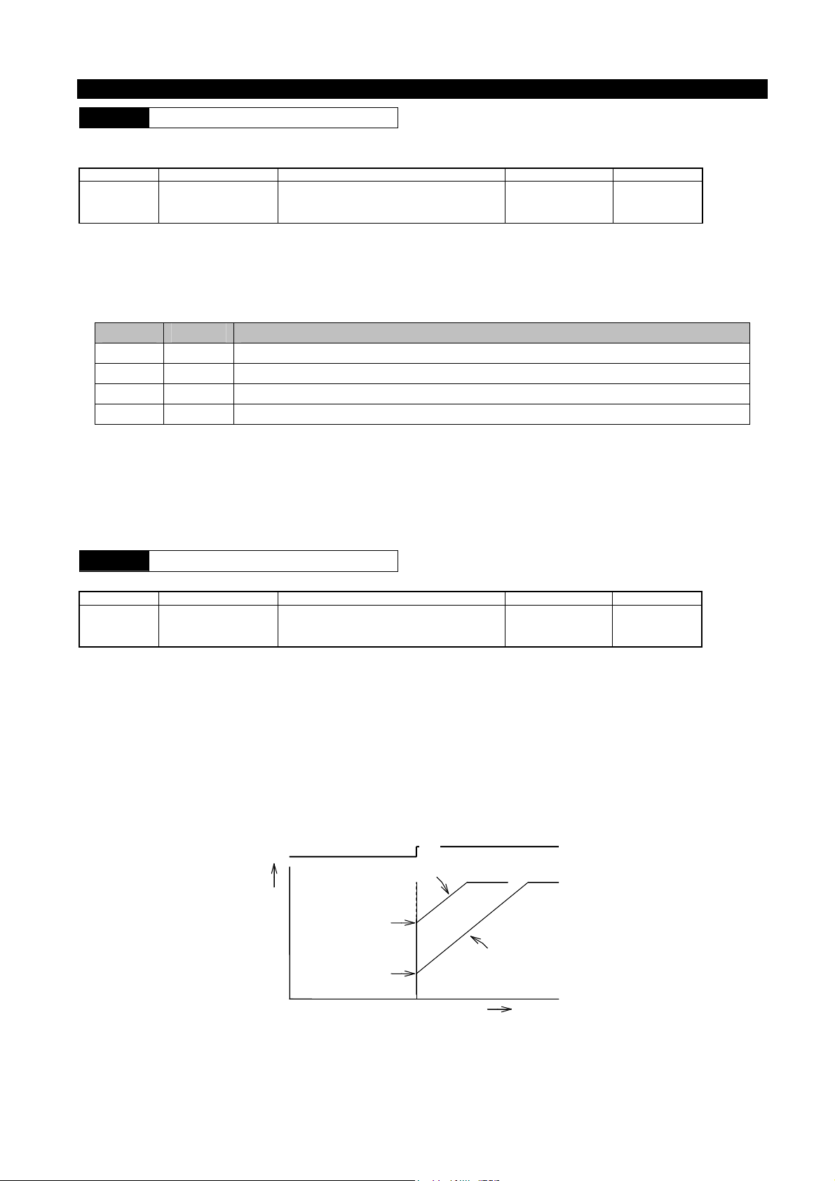
Starting • control function
F1101
Operation command selection
A function for selecting whether the operation/stop command of inverter is sent through operation panel or through external signals.
Code No. Function Name Data Content Setting Resolution Factory Presets
F1101 Operation command
selection
1:Operation panel
2:External terminal
3:Communication
1 1
● When F1101=2 (external terminal), the input signals of control terminals FR and RR are active. Other control terminal inputs are
always active because they are not related to F1101 data.
● The operation control authorization can be set using external terminals POPE and RCOM. When using external terminals, the
operation control authorization is as shown in the table below.
ROPE RCOM Operation Command
OFF OFF The method selected by F1101
ON OFF Operation panel
OFF ON Communication
ON ON Terminal block (FR terminal or RR terminal)
Note 1: When ROPE=OFF and RCOM=OFF, the operation control authorization of F1101 is active. When any one terminal of
ROPE and RCOM is ON, the operation control authorization depends on the terminal status of ROPE and RCOM
regardless of what the set status of F1101 is.
Note 2: Shutdown by『STOP』key on operation panel is always active regardless of the status of ROPE and RCOM terminals.
F1102
Starting method
A function for selecting the starting method.
Code No. Function Name Data Content Setting Resolution Factory Presets
F1102
Starting method
1:Starting frequency
2:Flying start
3:Starting frequency after DC braking
1 1
● The so-called "flying start" is a method for starting from the frequency corresponding to the motor speed detected so as to reduce
the impact at startup when the motor starts from idling condition. However, in this case, if there is an electromagnetic contactor
between the motor and the inverter, please set the electromagnetic contactor ON in advance, and then input operation signal.
● The so-called "started by starting frequency after DC braking" means the motor is stopped by DC braking before being started in
applications such as reverse run of fan against wind, in which the inverter is stopped while the motor is rotating due to other
factors. This is an effective method to reduce the impact at startup. See F1112- F1114 for DC braking setting.
● Flying start is executed when the alarm is automatically reset and restarted after momentary power failure regardless of the
setting value of F1102.
Operation signal
Output frequency
OFF
F1102=2
ON
Frequency
equivalent to
the motor speed
F1102=1
Starting frequency
t=0
Time
- 79 -

Note 1: The flying start function may not be effective when the capacity of the inverter is much larger than that of the motor or
when the free-running speed of the motor is very low or in an environment tends to be disturbed.
Note 2: If the inverter starts a free-running motor with a low frequency, an excessive current may be generated and trip the circuit
breakers. Thus, whether current startup will cause impact can be determined not only by checking the rotation speed but
also the direction of rotation. This function can start the motor in a predetermined rotation direction without any shock
even when the motor is free-running in reverse, for example due to a back wind.
Braking mode= free-running stop (F1111=3)
Motor rotation direction
Forward run Free running Decelerating to stop (speed tracking)
Same with normal starting
Reverse run
In normal
acceleration
FR (Forward run)
RR (Reverse run)
Forward run
Output frequency
Reverse run
Note 3: In feedback control such as PID control etc., it is possible that the speed tracking does not happen when configuring the
gain setting value or when affected by response speed of the system.
F1103
Starting frequency
The inverter starts to operate with this frequency. If the set frequency is lower than starting frequency, the inverter does not start.
Code No. Function Name Data Content Setting Resolution Factory Presets
F1103
Starting frequency
0.05~60Hz
0.01Hz 1
Example 1) When setting F1103=20Hz for 50Hz operation, if operation signal is turned on, the inverter outputs 20Hz as the output
frequency, and then goes up to 50Hz according to the specified acceleration slope.
Example 2) When setting F1103=20Hz for 15Hz operation, if operation signal is turned on, the inverter remains in standby and does
not output.
● Once the inverter starts, it continues to run even if a frequency lower than the starting frequency (but higher than operation start
frequency) is set..
● When inputting a stop signal, if the output frequency is below starting frequency, the inverter will stop outputting. (When DC
braking function is disabled).
F1104
Operation start frequency
This frequency value is used to determine whether the inverter can operate or not.
Code No. Function Name Data Content Setting Resolution Factory Presets
F1104
Operation start frequency
0~20Hz
0.01Hz 1
● If the set frequency equals or exceeds the levels of the operation start frequency and the starting frequency, the inverter starts
operating at the starting frequency. And, if a frequency below the operation start frequency is set during operation, the inverter
enters a standby state. And the output frequency drops to the starting frequency and then output stops. In this case, the operation
mode indicator on the operation panel flashes, indicating the standby state. This function is useful for starting or stopping the
inverter using only an external frequency command.
Example) F1104=20Hz, F1002=3 for the frequency setting using the quick knob. By adjusting the quick knob, the output starts
when the command frequency is 20Hz or higher. At a frequency lower than 20Hz, the output frequency goes down to the
starting frequency, and output stops.
- 80 -

F1105
Start delay time
This function is used to set the time until the inverter starts operation after inputting an operation signal.
Code No. Function Name Data Content Setting Resolution Factory Presets
F1105
Start delay time
0~5s
0.1 0
● This function is useful for setting the delay time with a sequence circuit for changeover between inverter/mains power, etc.
● When a switch between the motor and the inverter turns on at the same time as input of the operation signal, set F1105 to
approximately 0.5 sec.
Operation signal
O
Output frequency
Time
Delay time
F1106
F1107
Start standby time
Start standby frequency
Through the use of output frequency standby function, this function is used to keep the big inertia load in temporary standby by
increasing the frequency when starting and to increase frequency when the speed goes up, so as to facilitate a smooth acceleration.
Code No. Function Name Data Content Setting Resolution Factory Presets
F1106
F1107
Start standby time
Start standby frequency
0.0~120.0s
0.05~60.0Hz
0.1s 0
0.01Hz 5
● In the F1106, if a value other than 0 is set, when the frequency set by F1107 is reached by acceleration, the frequency increase
can be locked only by using the time set by F1106 (output frequency standby)
Note 1: This function is inactive when the acceleration/deceleration curve is S-shaped curve (F1010 = 2).
Note 2: If the starting frequency setting is higher than standby frequency, use the starting frequency to realize standby.
Note 3: If target frequency is lower than the standby frequency, standby action will not be executed.
Note 4: Standby action will not be executed during deceleration.
Target frequency
During deceleration
During acceleration During acceleration
Standby frequency
F1107
Standby time Standby time
F1106
F1106
Starting frequency
F1103 Time
F1108
Restart after momentary power failure
Whether the inverter resumes operation after it stops due to a momentary power failure can be specified using this function. This
function works properly only after a momentary power failure. If the duration of the power failure is longer, correct action can not be
made as the control power supply is lost, as shown in the following table.
Code No. Function Name Data Content Setting Resolution Factory Presets
F1108
Restart after momentary power
failure
0:Do not restart
1:Restart
2:Compensation for momentary
power failure
1 0
- 81 -

Short time power failure (momentary failure)
Long power failure (Re-start of the inverter)
External terminals External terminals
F1108
Operation
panel
Operation signal
Operation
panel
Operation signal No operation signal
0:Do not
restart
1:Restart
2:Restart
No restart No restart No restart Restart Restart No restart
Restart 1※ Restart 1※ No restart Restart Restart No restart
Restart 1※ Restart 1※ No restart Restart Restart No restart
The restart marked with 1 means that t※ he inverter starts in the flying start mode after a momentary power failure.
● When “F1108=2” is selected, the Momentary Power Failure Compensation function is enabled to prolong the operation time of
the inverter even in the event of a power failure. The Momentary Power Failure Compensation function detects a drop in the
input voltage, and reduces the output frequency and voltage of the inverter before any alarm trip, and uses the energy regenerated
from the motor to keep it operating for longer.
Note 1: The Momentary Power Failure Compensation function works when F1001: the motor control mode is V/f control or
speed control (F1001=1, 2, 3).
Note 2: While the Momentary Power Failure Compensation function is working, the output frequency of the inverter is reduced.
Use this function for loads, of which the frequency reduction is allowable.
Note 3: Restart after momentary power failure for F1108 = 2 has the same “restart” effect as for F1108 = 1.
Note 4: In the PID control, sometimes the Momentary Power Failure Compensation function can not be fully functional as a
result of the effects of PID gain setting value and the system response speed.
Note 5: Output voltage AVR function is needed to execute the Momentary Power Failure Compensation function in V / f control
mode. Therefore, to use this function, please set the reference voltage to F1005≠0
F1109
Direction of rotation of motor
This function is used to restrict the rotation of the motor to a fixed direction for safety reasons etc.
CodeNo Function Name Data Content Setting Resolution Factory Presets
F1109
Direction of rotation of motor
1:Forward and reverse run
2:Forward run only
3:Reverse run only
1 1
Note 1: The terms "forward run" and "reverse run" and the actual motor shaft rotation direction changes depending on the motor
structure and inverter connection method. For the inverter, when the "forward run" or "reverse run" command is given,
the user should confirm it directly during test run.
Note 2:The rotation direction of【DRIVE】key on the operation panel is determined by F1110.
F1110
Direction of rotation of motor
(set from operation panel)
Set the rotation direction at the【DRIVE】key on operation panel.
Code No. Function Name Data Content Setting Resolution Factory Presets
F1110 Motor rotation direction
(Operation panel 设定)
1:Forward run
2:
Reverse run
1 1
F1111
Braking method
Note: Use F1109 to fix the motor rotation direction.
Code No. Function Name Data Content Setting Resolution Factory Presets
F1111
Braking method
1:Deceleration to stop
2:Deceleration to stop + DC braking
3:Free run stop
1 1
● Deceleration to stop
A normal stop method for reducing output frequency according to the settings of acceleration/deceleration curve (F1010) and the
deceleration time (F1016 - F1019).
● Deceleration to stop + DC braking
Similar to the case of F1111 = 1, this method is used to reduce the output frequency to the time point below DC braking start
- 82 -

frequency (F1112); DC braking quickly stops the motor which is working. The DC braking time and DC braking force are
determined according to F1113 and F1114.
● Free run stop
Turn OFF all drive signals of the switching device at the time when a stop signal is sent to put the motor in free run state.
F1112
F1113
F1114
DC braking start frequency
DC braking time
DC braking force
A function for setting DC braking start frequency and action time and braking force when braking.
Code No. Function Name Data Content Setting Resolution Factory Presets
F1112
F1113
F1114
DC braking start frequency
DC braking time
DC braking force
0.05~20Hz
0.1~10s
1~10
0.01Hz 0.5
0.1s 2
1 5
● If F1111 = 2, the output frequency drops as the stop signal is input, DC braking starts at the time point where the value is below
the frequency set by F1112.
● When F1111=2, the starting frequency (F1103) is inactive during braking. When output frequency drops to the DC braking start
frequency (F1112), the DC braking starts.
● For DC braking action at starting means that the DC braking starts after the operation signal has met the starting conditions, and
then the motor will be started by starting frequency. In this case, the action time and braking force are the setting values of F1113
and F1114. See also F1102 for Dc braking action at starting.
● After the operation signal has been input, if the set frequency is below the operation start frequency or DC braking start
frequency, the following actions will be executed according to the magnitude relation between operation start frequency and DC
braking start frequency.
① ① Operation start frequency ≥ DC braking start frequency.
If the set frequency is lower than the DC braking start frequency, even if it is higher than DC braking start frequency, the
output frequency will be decreased to DC braking start frequency, and then DC braking starts.
② Operation start frequency < DC braking start frequency.
· Even if the set frequency is lower than DC braking start frequency, as long as it is greater than the operation start frequency,
the operation will continue.
· When the output frequency is higher than DC braking start frequency, even if the set frequency is lower than the operation
start frequency, like in ①, the output frequency will be decreased to DC braking start frequency, and then DC braking starts.
· When the output frequency is lower than DC braking start frequency, if the set frequency is lower than the operation start
frequency, then DC braking will start immediately.
● During DC braking, if the【STOP】key is pressed again, the DC braking will be released.
● During DC braking in stopped state, if the operation signal is input, then the operation will be restarted in the normal operation
order.
Note 1: F1113 and F1114 are active only in V/f mode (F1001=1, 40). In speed control mode (F1001=2, 3, 10, 11), the setting of
F6005-F6008 is equivalent to this setting.
Note 2: During DC braking, the motor tends to be over-heated as there is no self-cooling effect caused by motor rotation.
Therefore, the DC braking force should be set to a smaller value, and it is recommended to set the value within the range
in which the motor does not overheat or to install a temperature limiting relay on the motor.
Note 3: If the increase in DC braking force is ineffective, the possible reason is that current limiting function is activated by
overcurrent caused by some reason.
F1115
Duty cycle of brake resistor
A function for setting utilization rate of a brake resistor. The value shall be set within the allowable utilization rate of the brake resistor.
Code No. Function Name Data Content Setting Resolution Factory Presets
F1115
Duty cycle of brake resistor
0:No brake resistor
2~25%ED
98 : No discharge resistor protection ( with
discharge
※1)
1%ED
※2
- 83 -

99:External brake unit
Note: In case of braking through an external circuit, please set F1115 = 99.
*1 Since the protection actions will not be executed when F1115 = 98, the discharge resistor and the device may be damaged.
Please note this when setting.
*2 The representative parameters that are suitable for various models have been input.
When setting F1115 = 2-25, if it is judged that excessive current will flow in the brake resistor for a long time, in order to prevent the
brake resistor connected from burning damage, the actions of braking circuit drive element shall be stopped in a certain period of time.
F1116
Discharge resistor on signal output time
This function is used to output signals from a multifunctional output terminal for the time set with F1116 when the discharge resistor
for regenerated power discharge is turned on.
Code No. Function Name Data Content Setting Resolution Factory Presets
F1116
Discharge resistor on signal
output time
0.01~10s
0.01s 0.1
● Set one of F1509-F1511 to“32” for the multifunctional output terminal setting. The discharge resistor on signal is output from the
terminal which is set to“32”.
● During regenerated energy discharge, the discharge resistor switches between ON and OFF very quickly and repeatedly. The
Discharge Resistor on Signal function facilitates the measurement of this high-speed on/off operation with a narrow pulse width
in external equipment. The narrow pulse width of the on/off operation is expanded by the time set with F1116 and output by a
multifunctional output terminal.
Example) When the Discharge Resistor on Time F1116=0.1 (s).
Discharge resistor
ON/OFF signal
Multifunctional output =32
ON/OFF signal
Display Function
F1201
Monitor display selection
A function for switching the display contents of operation panel.
Code No. Function Name Data Content Setting Resolution Factory Presets
F1201
Monitor display selection
1:Frequency(Hz)
2:Output current(A)
3:Speed of rotation(rpm)
4:Load factor(%)
5:No unit display
1 1
● The change of the display value and display method in stopped state, standby state as well as operating state is shown in the
following table.
F1201
1 Flashing output frequency Normally-on output frequency
2 Flashing 0 [A] Normally-on output current
3
4 Flashing 0 [%] Normally-on load factor
5 The output monitor can be changed using F1202.
Flashing speed (※1)
Stopped Standby/Operating
Normally-on speed (*1)
(※1)The display contents may vary depending the motor control mode. The display contents are as shown in the table below.
Motor control mode
Sensorless vector control Estimated speed of motor 0
Others
(V/f·vector)
In operation (operating) Stopped
Detecting speed of PG sensor Detecting speed of PG sensor
Note: By using F1603, this code can be set even when the operation function is locked.
- 84 -

F1202
State display selection
This function is used to select output data displayed on the 7-segment monitor on the operation panel in No-Units Display mode.
Code No. Function Name Data Content Setting Resolution Factory Presets
F1202
State display selection
1:No units(multiple of F1203)
2:Output voltage [V]
3:DC voltage [V]
4:Active power [kW]
5:Apparent power [kVA]
6:Radiator temperature [℃]
7:Command speed [rpm]
8:PID1 feedback value [Hz]
9:PID2 feedback value [Hz]
10:VIF1 analog input value [Hz]
11:VRF/IRF analog input value [Hz]
12:Reserved
13:Output torque [%]
14:Partial excitation current [A]
15:Partial torque current [A]
16:Detecting position [mm]
29:Command frequency [Hz]
30:Command torque [%]
35:Reserved
target frequency [Hz]
44:
45:
output frequency [Hz]
1 1
● Output voltage: the output voltage of inverter.
● DC voltage: the value of DC voltage applied to the inverter.
● Active power: the actual power consumed on load.
● Apparent power: the apparent power is used for displaying inverter output.
● Radiator temperature: internal radiator temperature.
● Command speed: the speed given by a command.
● PID feedback value: the feedback value of PID control.
● VIF analog input value: an analog signal value generated by voltage or current.
● Command frequency: the frequency given by a command.
The following display contents is shown only when the value of F1001 = 2, 3, 4, 5, 6.
● Output torque: ratio of output torque to the rated torque.
● Partial excitation current: the current value for providing motor excitation.
● Partial torque current: the current value for providing motor torque.
● Command torque: the torque given by a command.
The following display contents is shown only when the value of F1001 = 6.
● Detecting position: the detecting position in position control.(Option)
※ When three detecting positions are selected, even if the positioning is finished, " . " will not be displayed.
F1203
Multiple for no-units display
This function is used when No-Units Display mode is displayed on the 7-segment monitor on the operation panel. This function is used
for setting the multiple which is multiplied with output frequency when F1202 = 1 (no-units display) .
Code No. Function Name Data Content Setting Resolution Factory Presets
F1203
Multiple for no-units display
0~100
0.01 1
● This function is used in applications where linear velocity etc. is displayed in a simple way.
- 85 -

Auxiliary functions
F1301
F1302
F1303
F1304
F1305
F1306
1st jump bottom frequency
1st jump top frequency
2nd jump bottom frequency
2nd jump top frequency
3rd jump bottom frequency
3rd jump top frequency
For the inverter-driven motor, resonance generated in the co-ordination between output frequency (speed) and the mechanical system
produce larger vibration and noise, and the power frequency hopping sometimes cause the change in output voltage. In this case, the
frequency which generates mechanical vibration and voltage change will be jumped during operation.
Code No. Function Name Data Content Setting Resolution Factory Presets
F1301
F1302
F1303
F1304
F1305
F1306
1st jump bottom frequency
1st jump top frequency
2nd jump bottom frequency
2nd jump top frequency
3rd jump bottom frequency
3rd jump top frequency
0~400Hz
0~400Hz
0~400Hz
0~400Hz
0~400Hz
0~400Hz
0.01Hz 0
0.01Hz 0
0.01Hz 0
0.01Hz 0
0.01Hz 0
0.01Hz 0
● Three different frequencies to skip can be specified.
● The frequency jumps between the top frequency and bottom frequency set by F1301-F1306. However, no jump occurs during
acceleration/deceleration.
Example 1) F1301=48Hz and F1302=52Hz.
1) If the target frequency is set to 51Hz: the inverter continues to operate at 48Hz.
2) If the target frequency is set to 53Hz: normal acceleration skips 48-52Hz and reaches 53Hz at which the inverter continues to
operate.
Example 2) F1301=39Hz, F1302=43Hz, F1303=41Hz and F1304=46Hz.
Jump frequencies are combined, and the range from 39-46Hz is skipped.
Actual
frequency
Jump frequency top
Jump width
Jump frequency bottom
Actual
frequency
Jump width
2nd jump frequency top
1st jump frequency top
2nd jump frequency bottom
1st jump frequency
bottom
F1301=48 F1302=52Hz
Example 1 Example 2
● The 1st, 2nd and 3rd jump frequencies can be set independently, for example, 2nd jump frequency> 1st jump frequency> 3rd
jump frequency.
● The top value and the bottom value of a jump frequency can not be reversely set. Therefore, when setting the top value or the
bottom value, set the values in the correct order so that the top and bottom values are not reversed. (Because in the initial settings,
both the top and bottom values are specified as 0, setting the bottom value first will cause an error, such setting is prohibited.)
● When the upper frequency limit (F1007) or the lower frequency limit (F1008) is set within the jump frequency band, the
frequency will jump within the range of the upper frequency limit and lower frequency limit.
● Setting a jump frequency band that includes both the upper frequency limit (F1007) or highest frequency and the lower frequency
limit (F1008) is prohibited for safety reasons.
- 86 -

F1307
Auto alarm recovery
This function code automatically specifies whether the inverter restarts after the inverter is tripped by protection function due to
overcurrent or overvoltage.
Code No. Function Name Data Content Setting Resolution Factory Presets
F1307
Auto alarm recovery
0:No auto reset function
1:Auto reset function
1 0
● The inverter restarts in the flying start mode. And, the alarm relay does not work when the inverter is restarted.
● If three consecutive trips occur in 10 seconds, the status of 3rd trip alarm will be kept, and the alarm relay works.
● When an alarm for which auto reset is possible occurs during standby and then is released, the reset method depends on the status
at that time.
Standby: Keeps standby.
If operation conditions are established: Setting of starting frequency is inactivated by flying start.
● When an alarm for which auto reset is possible occurs during deceleration caused by the stop signal and then is released, auto
reset is performed in the alarm stop status. But operation is not restarted.
● Auto reset is possible with the following alarms:
Abnormal main switching device temperature
Overcurrent during acceleration
Overcurrent during constant speed
Overcurrent during deceleration
Short-time overload during acceleration
Short-time overload during constant speed
Short-time overload during deceleration
Overvoltage during acceleration
Overvoltage during constant speed
Overvoltage during deceleration
F1308
Instability elimination
When the inverter is used to drive a motor, the dead time to protect a switching device from a short circuit may make the current
unstable. If the current becomes unstable, the motor may generate vibration or abnormal noises. In addition, compared with the stable
current, the current value may become greater. The instability elimination function is used to avoid this problem.
Code No. Function Name Data Content Setting Resolution Factory Presets
F1308
Instability elimination
0~20
1 0
● The larger the value specified, the greater the compensation. Therefore, increase the value gradually to set the value at which
instability is eliminated.
F1309
Operation direction switching in V / f
control mode
This function specifies the action for operation direction switching in V / f control mode.
Code No. Function Name Data Content Setting Resolution Factory Presets
1309
Operation direction switching in V /
f control mode
0:Start from the direction opposite to current
direction after a stop
1:Continuous operation
1
0
●When F1309 = 0, the start and stop-related functions are executed in accordance with the values of the function codes. The operation
stops according to the function code. Then, the operation immediately starts from the direction opposite to current direction in
accordance with the setting value of the function code. However, when switching the direction of operation, neither the DC braking in
stopped state nor the DC braking at start works.
●When F1309 =1, regardless of function codes related to start or stop, acceleration will be executed consecutively in opposite direction
after deceleration. When switching the direction of operation, the output frequency is continuously variable and the rotation direction
can be switched smoothly.
Note 1: When F1309=0, the stop or start is executed in the mode specified by the function code. Therefore, the output frequency near
0Hz is not continuously variable. And, because DC braking is executed, if the starting frequency or DC braking start
frequency is set with a too big value, motor vibration and overcurrent alarm may occur.
Chapter 7
- 87 -

Note 2: When reverse run speed tracking function is set, regardless of the setting of F1309, rotation direction switching is a continuous
action.
Note 3: In speed control mode, regardless of the setting of F1309, rotation direction switching is a continuous action.
F1315
Shortest operation time function
Even when a brief operation signal is input via an external control terminal, this function holds the operation command for the time set
by the shortest operation time function.
Code No. Function Name Data Content Setting Resolution Factory Presets
F1315
Shortest operation time
function
0~99.99s
0.1s 0
● During operation by the external control terminal, the function defines the minimum ON width for the input signal of
multifunctional input terminal FR or RR. In other words, the function starts counting when the input signal turns on, and the
signal is assumed to remain on for the duration of the count even if the multifunctional input terminal FR or RR is set to off.
After the time set by F1315, the inverter operates again according to the current status of multifunctional input terminal FR or
RR.
●
External operation signal
FR or RR
Internal operation signal of inverter
Shortest operation time
F1315
Note 1: If the time setting of F1315 is changed while the shortest operation time function is counting the time, the new value will
become active from the next time.
Note 2: This function is active only when operation command selection: F1101=2.
F1316
F1317
2nd Upper frequency limit
3rd Upper frequency limit
A function for setting the upper limit of output frequency. If 2MAX is set to ON using multifunctional input terminals (F1414 - F1421),
then the 2nd Upper frequency limit will be used to limit frequency, if 3MAX is set to ON, then 3rd Upper frequency limit will be used.
If both of them are set to ON, then the upper frequency limit of F1007 will be used for limiting frequency.
Code No. Function Name Data Content Setting Resolution Factory Presets
F1316
F1317
2nd Upper frequency limit
3rd Upper frequency limit
5~400Hz
5~400Hz
0.01Hz 60
0.01Hz 60
F1318
Cooling fan ON/OFF control
This function is used to select the action of cooling fan for cooling inverter.
Code No. Function Name Data Content Setting Resolution Factory Presets
F1318
Cooling fan ON/OFF control
0:ON/OFF control
1:Normally ON
1 0
● When ON/OFF control is selected, fan ON/OFF control will be automatically executed according to the radiator temperature.
Note: In power-on test after the fan has been replaced, check that the fan is set to normally ON.
F1319
Functions corresponding to high altitude areas
In high altitude areas, due to the unit cooling capacity, the current derating rate of parts and other reasons, it is recommended to use
Larger inverters by one rank. However, when used in high-altitude areas of more than 1,000m above sea level, the rated current can be
derated, and this function should be used for selecting suitable altitude where applicable.
Code No. Function Name Data Content Setting Resolution Factory Presets
F1319
Functions corresponding to
high altitude areas
1:1,000m or below
2:1,000~1,500m or below
3:1,500~2,000m or below
4:2,000~2,500m or below
5:2,500~3,000m
1 1
● The current derating rate of inverter for each altitude range is as shown below.
Content Current derating rate
- 88 -

1,000m or below
1,000~1,500m or below
1,500~2,000m or below
2,000~2,500m or below
2,500~3,000m
1
0.966
0.925
0.900
0.876
F1320
Rating selection
A function which changes the rating to mode A for heavy load or mode B for light load.
Code No. Function Name Data Content Setting Resolution Factory Presets
F1320
Rating selection
1:A MODEL(heavy load mode)
2:B MODEL(light load mode)
1 2
● Mode A (heavy load) allows an overload capacity of 150% per minute.
● Mode B (light load) allows an overload capacity of 120% per minute.
Note: If the mode is switched by specification selection, then the relevant function codes shall be initialized.
e.g.) F1009, F1701, F1704, F5001, F6001 and F6102.
7-3-2 Input/Output-Related Functions
Input/Output-Related Functions
The function blocks of input and output terminals of the inverter control circuit are described as follows.
F1401
F1402
F1403
F1404
In case of setting output frequency using the analog signal, these functions are used to set a frequency (bias frequency) corresponding
to minimum analog signal value (0V or 4mA) and a frequency (gain frequency) corresponding to maximum value (5V or 10V and
20mA).
Code No. Function Name Data Content Setting Resolution Factory Presets
F1401
F1403
F1402
F1404
The relation between the analog frequency setting signal (VRF1,VRF/IRF) and the inverter output frequency is shown as follows.
Setting example: When F1401 =- 10.0 (-10Hz), F1402 = 90.0 (90 Hz), and F1002 = 3 (frequency setting VIF1: 0 - 10V), the output
frequency is as shown below.
Bias frequency(VRF1)
Gain frequency(VRF1)
Bias frequency(VRF/IRF)
Gain frequency(VRF/IRF)
Bias frequency(VRF1)
Bias frequency(VRF/IRF)
Gain frequency(VRF1)
Gain frequency(VRF/IRF)
0~±400Hz
0.1Hz 0
(frequency at 0V or 4mA)
In case of negative value, -XXXX will be
displayed.
0~±400Hz
(frequency at 5V or 10V or 20 m)
In case of negative value, -XXXX will be
displayed.
0.1Hz 60
Gain
frequency
Output
frequency
Analog frequency
setting signal
Bias frequency
Below
Output
frequency
(Noise control: Do not use a signal of less than 1V.)
Analog frequency setting signal
Chapter 7
- 89 -

By taking advantage of bias and gain frequencies, a common analog signal for frequency commands can be input to more than one
inverter for proportional operation.
Example) Input 0 - 10V analog signals to two inverters, so that 1st and 2nd inverters deliver output frequencies with a ratio of 1:2
for the purpose of proportional operation.
Setting of 1st inverter: F1401=0.0(0 Hz),
F1402=50.0(50 Hz)
Setting of 2nd inverter: F1401=0.0(0 Hz),
F1402=100.0(100 Hz)
(Adjust the acceleration/deceleration time as required.)
Note 1: In negative setting frequency field, the output frequency is 0 Hz.
Note 2: For PID control, the bias and gain frequencies apply to the feedback signal.
F1407
F1408
External analog input filter time constant(VRF1)
External analog input filter time constant
(VRF/IRF)
Functions for setting the filter time constant of external analog signal input.
Code No. Function Name Data Content Setting Resolution Factory Presets
F1407
F1408
External analog input filter time
(VRF1)
constant
External analog input filter time
(VRF/IRF)
constant
1~500
(set value 1=10ms)
1
(10ms)
10
If interference is detected in external analog signals, adjust the external analog input filter time constant.
Set the time constant to N × 10 ms (N = 1 to 500), the setting range is 10 to 5,000 ms.
Filters can be assigned to VIF1, VIF2 and VIF3 independently.
F1410
F1411
Set frequency gain
Analog input switching for set
frequency gain
Using an external analog input terminal, the gain is adjustable when setting frequency.
Code No. Function Name Data Content Setting Resolution Factory Presets
F1410
F1411
Set frequency gain
Analog input switching for set
frequency gain
0~100%
0:No analog input
1:External analog VRF1voltage(0~5V)
2:External analog VRF1voltage(0 ~10Vor
potentiometer)
3:External analog VRF/IRFvoltage(0~5V)
4:External analog VRF/IRFvoltage(0~10Vor
potentiometer)
5:Reserved
6:Reserved
7:Reserved
8:External analog VRF/IRFcurrent(4~20mA)
9:Reserved
1% 0
1 0
● When several inverters are used for proportional operation, this function is useful for fine adjustment of the command frequencies
of the inverters from the master to the slave.
● The external analog input terminal is switched with F1411 (Analog input switching for set frequency gain).
● Use F1410 as the set frequency value for proportional operation.
Example 2) When the set frequency is 50Hz, F1410 = 50%, if the external analog input is 0 - 10V
- 90 -

VRF1 or RF input
· 在 0V 时,50Hz-(50Hz×50%)=25Hz。
· 在 5V 时,50Hz-(50Hz×0%)=50Hz。
· 在 10V 时,50Hz+(50Hz×50%)=75Hz。
F1412
MBS terminal input mode
This function is used to select the input signal action of multifunction input terminal MBS.
Code No. Function Name Data Content Setting Resolution Factory Presets
F1412
MBS terminal input mode
1:Level triggered
2:Edge triggered
1 1
Edge operation will accept MBS input once between OFF and ON.
F1413
ES input terminal function
This function can be used for switching the function of control input terminal “ES”.
Code No. Function Name Data Content Setting Resolution Factory Presets
F1413
ES input terminal function
external thermistor signal
1:NO
2:NC
external thermistor signal
1 1
The function shall be switched according to the contact type.
F1413=1: ES terminal (external thermistor input terminal) is connected with an NO (normally open) contact.
F1413=2: ES terminal (external thermistor input terminal) is connected with an NC (normally closed) contact.
F1414
F1415
F1416
F1417
F1418
F1419
F1420
F1421
Selection of input terminal DI1
Selection of input terminal DI2
Selection of input terminal DI3
Selection of input terminal DI4
Selection of input terminal DI5
Selection of input terminal DI6
Selection of input terminal DI7
Selection of input terminal DI8
These functions are used to assign functions to the digital multifunctional input terminals DI1 - DI8 arbitrarily through data selection.
Code No. Function Name Data Content Setting Resolution Factory
F1414
F1415
F1416
F1417
F1418
F1419
F1420
Selection of input
terminal DI1
Selection of input
terminal DI2
Selection of input
terminal DI3
Selection of input
terminal DI4
Selection of input
terminal DI5
Selection of input
terminal DI6
Selection of input
terminal DI7
0:
Unused 1: FR
2: RR 3: 2DF
4: 3DF 5: MBS
6: ES 7: RST
8: AD2
9: AD3 10: JOG
11: 5DF 12: 9DF
13: FR+JOG 14: RR+JOG
15: FR+AD2
16: RR+AD2 17: FR+AD3
18: RR+AD3 19: FR+2DF
20: RR+2DF 21: FR+3DF
22: RR+3DF 23: FR+2DF+3DF
24: RR+2DF+3DF 25: FR+AD2+2DF
26: RR+AD2+2DF 27: FR+AD2+3DF
28: RR+AD2+3DF
29: FR+AD2+2DF+3DF
30: RR+AD2+2DF+3DF
31: FR+AD3+2DF 32: RR+AD3+2DF
33: FR+AD3+3DF 34: RR+AD3+3DF
35: FR+AD3+2DF+3DF
36: RR+AD3+2DF+3DF
37: PTR 39: FR+5DF 40:HD
45: CP(Optional) 46: CCL
1 1
2
3
4
5
6
7
Presets
Chapter 7
- 91 -

F1421
Selection of input
terminal DI8
47: PC(Optional) 57: P0
58: FR+CCL 59: FR+RCCL
64: FR+MBS 65: RR+MBS
67: 2DF+AD2 68: 2DF+AD3
69: 3DF+AD2 70: 3DF+AD3
71: A×10(Optional) 72: A×100 (Optional)
74: 2MAX 75: 3MAX
76: VFPID 77: PIDLCK
83: For factory adjustment 84: S2
85: PIDL 86: PIDH
87: RPID1 88: PID1EX
89: PID2EX 91: IHOLD
92: ICLEAR 109: RCCL
114:1DFA 115: 1DFB
116: 1DFA+1DFB 117: ROPE
118:RCOM 119: ROPE+RCOM
120: 1DFA+ROPE 121: 1DFB+RCOM
122:1DFA+1DFB+ROPE+RCOM
253~255:For factory adjustment
8
Digital multifunctional input terminals DI1 - DI8 can be set into any one of the functions by using the corresponding function codes
F1414 - F1421.
Also, for multiplexed terminal, several functions can be input to one terminal.
For example, if F1414=13, Jog operation can be realized by connecting DI1 terminal.
Table 7-1 Multifunctional input codes
Function code
No.
F1414 DI1
F1415 DI2
F1416 DI3
F1417 DI4
F1418 DI5
F1419 DI6
F1420 DI7
F1421 DI8
Input terminal name Data range
0~255
Initial value
(symbol)
1 (FR)
2 (RR)
3 (2DF)
4 (3DF)
5 (MBS)
6 (ES)
7 (RST)
8 (AD2)
Table 7-2 Multifunctional input signals
Data No.
Symbol Function Data No. Symbol Function
0 — Unused terminal 40 HD Operation signal hold command
1 FR Forward run command 45 CP Command pulse blocking signal (option)
2 RR Reverse run command 46 CCL Deviation counter clear signal
3 2DF Multi-speed command 1 47 PC P control signal
4 3DF Multi-speed command 2 57 P0 Zero speed command
5 MBS Free run command 58
6 ES External abnormal stop command 59
7 RST Alarm reset command 64
8 AD2 2nd, 4th acceleration/deceleration command
9 AD3 2nd, 4th acceleration/deceleration command
10 JOG Jog operation command 68
11 5DF Multi-speed command 3 69
12 9DF Multi-speed command 4 70
13
Multiplexed
14
Multiplexed
15
Multiplexed
16
Multiplexed
17
Multiplexed
18
Multiplexed
19
Multiplexed
20
Multiplexed
21
Multiplexed
22
Multiplexed
or up terminal
or down terminal
FR+JOG 71 A×10 Electric gear ×10 (option)
RR+JOG 72 A×100 Electric gear ×100 (option)
FR+AD2 74 2MAX 2nd Upper frequency limit selection 1※
RR+AD2 75 3MAX 3rd Upper frequency limit selection 2※
FR+AD3 76 VFPID V/f-PID control switching terminal
RR+AD3 77 PIDLCK PID control locking terminal
FR+2DF 83 For factory adjustment
RR+2DF 84 S2 2nd S-shaped acceleration / deceleration
FR+3DF 85 PIDL PID switching terminal (PIDL)
RR+3DF 86 PIDH PID switching terminal (PIDH)
65
67
Multiplexed
Multiplexed
Multiplexed
Multiplexed
Multiplexed
Multiplexed
Multiplexed
Multiplexed
FR+CCL
RR+CCL
FR+MBS
RR+MBS
2DF+AD2
2DF+AD3
3DF+AD2
3DF+AD3
time command
- 92 -

23
Multiplexed
24
Multiplexed
25
Multiplexed
26
Multiplexed
27
Multiplexed
28
Multiplexed
29
Multiplexed
30
Multiplexed
31
Multiplexed
32
Multiplexed
33
Multiplexed
34
Multiplexed
35
Multiplexed
36
Multiplexed
37 PTR
38 T-FCL Frequcy clear Teminal
39 Multiplexed FR+5DF
Multiplexed
FR+2DF+3DF 87 RPID1 PID1 reset terminal
RR+2DF+3DF 88 PID1EX PID1 External terminal selection
FR+AD2+2DF 89 PID2EX PID2 External terminal selection
RR+AD2+2DF 91 IHOLD PID integral value hold terminal
FR+AD2+3DF 92 ICLEAR PID integral value clear terminal
RR+AD2+3DF 109 RCCL Deviation counter reverse run clear signal
FR+AD2+2DF+3DF 114 1DFA 1st speed frequency selection 1
RR+AD2+2DF+3DF 115 1DFB 1st speed frequency selection 2
FR+AD3+2DF 116 Multiplexed
RR+AD3+2DF 117 ROPE Control authorization selection 1
FR+AD3+3DF 118 RCOM Control authorization selection 2
RR+AD3+3DF 119
FR+AD3+2DF+3DF 120
RR+AD3+2DF+3DF 121
Simple graph operation counter reset
signal
122
253~255
terminal
Multiplexed
Multiplexed
Multiplexed
Multiplexed
For factory adjustment
1DFA+1DFB
ROPE+RCOM
1DFA+ROPE
1DFB+RCOM
1DFA+1DFB+ROPE+RCOM
*1 When the terminal is set to ON, F1316: limits the frequency with the 2nd upper frequency limit.
*2 When the terminal is set to ON, F1317: limits the frequency with the 3rd upper frequency limit.
F1422
Reserved
F1423
F1424
Reference frequency for pulse train input
Effective number of bits for VIF1 detection
Effective number of bits for VRF/IRF detection
Functions for setting the resolution (effective number of bits) of external analog signal reading.
Code No. Function Name Data Content Setting Resolution Factory Presets
F1423
F1424
Effective number of bits for
VIF1 detection
8~12bit
1bit 12bit
Effective number of bits for
VRF/IRF detection
This function is used to make the detection value of external analog signal stable and effective where interference exists in the external
analog signal. And, if the effective number of bits is reduced, then the action in S-shaped acceleration/deceleration curve becomes
more stable.
Effective number of bits for VIF1, VRF/IRF ection = 8, when this value is set, 4 lower bits are inactive.
= 9, when this value is set, 3 lower bits are inactive.
= 10, when this value is set, 2 lower bits are inactive.
= 11, when this value is set, 1 lower bit is inactive.
= 12, when this value is set, no inactive bit.
Effective number of bits can be assigned to VIF1, VRF/IRF independently.
F1501
F1502
F1503
F1504
F1505
F1506
Internal analog output function1
Internal analog output coefficient 1
Internal analog output bias 1
Internal analog output function2
Internal analog output coefficient 2
Internal analog output bias 2
Functions for analog output (0-10V) of a variety of internal states of inverter between the control circuit terminal‘s analog output
terminals AOUT1, AOUT2 and analog signal common terminal ACM.
Code No. Function Name Data Content Setting Resolution Factory Presets
F1501
F1504
Internal analog output function1
Internal analog output function2
0:No function
1: Set frequency (Hz)
2:Output frequency [Hz]
3:PID1 feedback value [Hz]
1
0
Chapter 7
- 93 -

F1502
F1505
F1503
F1506
Internal analog output coefficient
1
Internal analog output
coefficient 2
Internal analog output bias 1
Internal analog output bias 2
4:PID2 feedback value [Hz]
5:Output current (A)
6:Output voltage [V]
7:DC voltage [V]
8:Radiator temperature [℃]
9:Load factor [%] (electric thermistor integrated
value)
10:Load factor [%] (ratio to rated current)
11:VRF1analog input value [V]
12:VRF/IRFanalog input value [V]
13:Reserved
14:Speed [rpm]
15:Active power [kW]
16:Apparent power [kVA]
17:PID1 command value [Hz]
18:PID1 input deviation value [Hz]
19:PID2 command value [Hz]
20:PID2 input deviation value [Hz]
21~23:For factory adjustment
24:External PID1 output value [Hz]
25:External PID2 output value [Hz]
26:For factory adjustment
35:Command frequency [Hz]
36:Command torque [%]
39:Reserved
99:For factory adjustment
0~20
0~±10V
0.01 1
0.1V 0
The methods of conversion between output values of possible output analog signal from AOUT1 or AOUT2 terminal and actual values
are shown in the table below.
F1501
F1504
Output signal content Conversion method
Set value
0 No function
1 Set frequency (Hz) 120Hz/10V
2 Output frequency [Hz] 120Hz/10V
3 PID1 feedback value [Hz] 120Hz/10V
4 PID2 feedback value [Hz] 120Hz/10V
5 Output current (A) *1
6 Output voltage [V] 500V/10V
7 DC voltage [V] 500V/5V
8
9 Load factor [%] (integral value of the electric
10 Load factor [%] (ratio to rated current) 100%/5V
11 VRF1analog input value [V]
12 VRF/IRFanalog input value [V]
13 Reserved
14 Speed [rpm] 1800rpm/5V
15 Active power [kW] 10kW/10V
16 Apparent power [kVA] 10kVA/10V
17 PID1 command value [Hz] 120Hz/10V
18 PID1 input deviation value [Hz] 120Hz/10V
19 PID2 command value [Hz] 120Hz/10V
20 PID2 input deviation value [Hz] 120Hz/10V
24 External PID1 output value [Hz] 120Hz/10V
25 External PID2 output value [Hz] 120Hz/10V
35 Command frequency [Hz] 120Hz/10V
36 Command torque [%]
Radiator temperature [℃] 100℃/8V
100%/5V
thermistor)
4-20mA current input,20mA/10V
0-5V voltage input,5V/5V
0-10V voltage input,10V/10V
400%/10V(※1)
*1 The positive and negative values of command torque are output with 5V as the center.(0V=-200%, 5V=0%, and
10V=200%)
Note 1: Maximum allowable current: 15mA.
(But, the converted value is no-load output voltage. If the output current increases, the output voltage will decrease.
In this case, the signal output can be adjusted using output coefficient.)
*1)Inverter capacity and output current conversion methods
Model
Output current signal conversion
method
- 94 -

S06-4A005-B**
S06-4A006-B**
S06-4A009-B** 20A/10V 50A/10V
S06-4A014-B**
S06-4A019-B**
S06-4A025-B** 50A/10V 100A/10V
S06-4A032-B**
S06-4A038-B**
S06-4A049-B** 100A/10V 250A/10V
S06-4A061-B**
S06-4A076-B**
S06-4A092-B**
S06-4A115-B** 250A/10V 500A/10V
S06-4A152-B** 500A/10V 500A/10V
A MODEL B MODEL
20A/10V 20A/10V
50A/10V 50A/10V
100A/10V 100A/10V
250A/10V 250A/10V
Output signals can be increased or decreased by the internal analog output coefficients F1502 and F1506. If the output signal from the
AOUT1 or AOUT2 terminal is not of an adequate level, the signal level can be adjusted by setting the internal analog output
coefficient.
F1502: Coefficient for F1501 (Internal Analog Output Function 1)
F1505: Coefficient for F1504 (Internal Analog Output Function 2)
Note 2: If the coefficients of F1502 and F1505 are smaller than 1, the output signals are decreased.
Bias voltage can be set for each output signal using F1503 or F1506 (internal analog output bias).
Although the negative bias voltage setting is possible, the output signal voltage will be 0V where the output signal voltage is negative.
Note 3: The PID controlled variables are output in the form of absolute value. In case of negative value, the output will be
positive.
F1507
Approach frequency
This function specifies the frequency at which a frequency arrival signal is output.
Code No. Function Name Data Content Setting Resolution Factory Presets
F1507 Approach frequency
0~400Hz
0.01Hz 10
If the value of any one of F1509 – F1511 is 7 (frequency arrival), the signal is output from control circuit output terminals DO1 to DO3
when the output frequency exceeds the value of F1507.”
Similarly, If the value of F1513 is 7 (frequency arrival), the signal is output from control circuit relay output terminals FA1, FB1 or
FC1 when the output frequency exceeds the value of F1507.”
Chapter 7
Output
frequency
F1507:Approach frequency setting value
Frequency approach signal Time
F1508
Frequency matching range
This function specifies the out frequency band corresponding to the frequency matching signal.
Code No. Function Name Data Content Setting Resolution Factory Presets
F1508 Frequency matching range
0~10Hz
0.01Hz 0
If the value of any one of F1509 – F1511 is 5, 6, 14 or 15, the signal is output from control circuit terminals DO1 to DO3 when the
output frequency falls within the value range between ±F1508.”
Similarly, for F1513, the signal is output from control circuit relay output terminals FA1, FB1 or FC1.
- 95 -

Note: When the frequency is specified using an analog signal, an appropriate setting should be specified using F1508 to
prevent frequency matching signal from chattering. When the vector control is active, the output frequency
constantly changes. Set F1508 to several Hz.
F1509
F1510
F1511
Selection of output terminal DO1
Selection of output terminal DO2
Selection of output terminal DO3
This function is used to select the required function from the multifunctional output terminals DO1-DO3 of control circuit terminals to
execute open-collector output.
Code No. Function Name Data Content Setting Resolution Factory Presets
F1509
F1510
F1511
Selection of output terminal
DO1
Selection of output terminal
DO2
Selection of output terminal
DO3
0:Unused 1:In operation 1
2:Undervoltage
3:End of simple scheduled operation
4:In operation 2
5:Frequency matching (1st speed frequency)
6:Frequency matching (1st to 16th speed frequencies)
7:Frequency approach
8:Overload alarm level setting signal (the value of
9:Electric thermistor pre-alarm signal
10:Radiator overheat pre-alarm signal
13:Excitation and DC braking signals
14:Lower frequency limit matching signal
15:Upper frequency limit matching signal
16:Servo on ready signal (option)
17:Zero servo completion signal (option)
18:FR signal 19:RR signal
20:2DF signal 21:3DF signal
22:5DF signal 23:9DF signal
24:AD2 signal 25:AD3 signal
26:JOG signal 27:MBS signal
28:ES signal 29:RST signal
31:Positioning completion signal (option)
32:Discharge resistor on signal
34: Frequency counter (output frequency)(※1)
35:Frequency counter (command frequency)(※1)
36:Overload alarm level setting signal
(Including when in acceleration/deceleration )
42:Torque matching signal
43:Low speed detection signal
47:Motor speed counter (※1)
48:Forward run detection signal
49:Reverse run detection signal
F1704)
1 1
5
8
*1 Can not be used together with the current output function. When outputting frequency counter, set F1515 = 0 to disable the
current output function.
Table 7-3 Multifunctional output signals
Data No. Function Action
0 Unused terminal.
1 In operation 1 Inverter in operation (gate signal on) on
2
3
4 In operation 2 Inverter in operation (except DC braking and exciting) is (gate signal on) on
5 Frequency matching (1st speed frequency)
6 Frequency matching (1st to 16th speed
7
8
9 Electric thermistor pre-alarm signal ON when the electric thermistor integral value is more than 80% of protection stop value.
10 Radiator overheat pre-alarm signal ON when radiator overheat protection alarm occurs
13 Excitation and DC braking signals ON during DC braking or excitation.
14
15
16
17
18
19
Undervoltage
End of simple scheduled operation
(※3)
frequencies)(※3)
Frequency approach(※3)
Overload alarm level setting signal (the
value of F1704)
Lower frequency limit matching signal(※
3)
Upper frequency limit matching signal(※
3)
Servo on ready signal
Zero servo completion signal
signal
FR
signal
RR
Undervoltage alarming ON.
On when simple scheduled operation ends
ON when the output frequency is equal to target frequency during 1st speed operation.
ON when the output frequency is equal to target frequency during 1st-16th speed operations.
Output frequency is F1507: On when the arrival frequency is exceeded.
Load status during normal operation is F1704: On when the overload pre-alarm value is
exceeded.
When output frequency is F1008: ON when the lower frequency limit and F1508 are the
same within the frequency matching range.
When output frequency is F1007: ON when the upper frequency limit and F1508 are the
same within the frequency matching range.
ON during position control operation except for during excitation
When the gate pole is ON under zero-servo, the position deviation F8121: ON if below
zero-servo completion range.
ON if the multifunctional input terminal FR is on.
ON if the multifunctional input terminal RR is on.
- 96 -

20
21
22
23
24
25
26
27
28
29
31
32
34
35 Frequency counter (command frequency)
36
42
43
47
48
49
2DF signal
3DF signal
5DFsignal
9DF signal
AD2 signal
AD3 signal
JOG signal
MBS signal
ES signal
RST signal
Positioning completion signal
Discharge resistor on signal
Frequency counter (output frequency)(※
1)
(※1)
Overload alarm level setting signal
(Including when in
acceleration/deceleration )
Torque matching signal
Low speed detection signal
Motor speed counter(※1)
Forward run detection signal(※2)
Reverse run detection signal(※2)
ON if the multifunctional input terminal 2DF is on.
ON if the multifunctional input terminal 3DF is on.
ON if the multifunctional input terminal 5DF is on.
ON if the multifunctional input terminal 9DF is on.
ON if the multifunctional input terminal AD2 is on.
ON if the multifunctional input terminal AD3 is on.
ON if the multifunctional input terminal JOG is on.
ON if the multifunctional input terminal MBS is on.
ON if the multifunctional input terminal ES is on.
ON if the multifunctional input terminal RST is on.
On if position deviation is less than F8111: positioning range in position control.
ON if the discharge resistor is on.
F1512: the output frequency calculated with counter output multiple.
F1512: the command frequency calculated with counter output multiple.
On when the load condition is F1704: above overload pre-alarm value.
ON when the motor torque is within the range specified by F1516: torque matching level and
F1517: torque matching range.
ON when the motor torque is within the range specified by F1518: low speed matching level
and F1519: low speed matching range.
Motor speed is output by the multiple specified by F1512: counter output multiple.
ON when the motor speed is greater than F1518: low speed matching range in forward run
direction.
ON when the motor speed is greater than F1518: low speed matching range in reverse run
direction.
*1 Can not be used together with the current output function. When outputting frequency counter or motor speed counter, set
F1515 = 0 to disable the current output function.
*2 If only single-phase pulse is input to PG input terminal, it can not detect the direction of rotation. Therefore, the rotation
direction signal can not be correctly output.
*3 No output in torque control or position control.
F1512
Counter output multiple
This function specifies the output multiple when the inverter’s output frequency, command frequency and motor speed are countered
and output to the control circuit output terminals (DO1-DO3).
Code No. Function Name Data Content Setting Resolution Factory Presets
F1512 Counter output multiple
1~100
1 1
The output multiple can be set where the inverter’s frequency and command frequency counter and motor speed counter (which can be
set with F1509 - F1511) are output from multifunctional output terminals DO1 - DO3. When motor speed counter multiple in F1512 is
1, 1 rpm indicates 0.1Hz, and the motor rotation direction is output to the forward run detection signal and reverse run detection signal.
Example 1) When F1512 = 1, the frequency will be output from the control signal output terminals at 1 time the output frequency
and command frequency of the inverter. When the inverter output frequency = 60 Hz, the frequency counter output =
60 Hz.
Example 2) When F1512 = 10, the frequency will be output from the control signal output terminals at 10 times the output
frequency and command frequency of the inverter. When the inverter output frequency = 60 Hz, the frequency counter
output = 600Hz.
Example 2) When F1512 = 10, the motor speed counter outputs 1500Hz with 1500rpm. (1rpm indicates 1Hz)
● Related functions
F1509-F1511=34: Frequency counter output (output frequency)
F1509-F1511=35: Frequency counter output (command frequency)
F1509-F1511=47: Motor speed counter
Note 1: The output range of frequency counter output is 1.5-1,500Hz. When the coefficient calculation result of frequency
counter output multiple is below 1.5Hz, the output is always OFF. And, 1,500 Hz is the limit when the frequency is
above 1,500 Hz.
Note 2: Output frequency is the actual frequency output by the inverter, and may be different from command frequency
according to the load condition in vector control mode. Even in constant speed operation under the vector control
mode, if a certain frequency counter output is required, set F1509 - F1511 = 35 (command frequency).
Chapter 7
- 97 -

Note 3: Depending on the impedance of peripheral device connected to, output waveform of the frequency counter may be
delayed and uneven duty cycle may be occurred. In order to reduce uneven duty cycle, please adjust the
impedance of the peripheral device to be 2KΩ or below in the range below 50mA to be flowed into open-collector.
F1513
F1514
Relay 1 contact output selection
Relay 2 contact output selection
This function is used to select and output control circuit output terminals FA1、FB1、FC1 and FA2、FB2、FC2 relay contacts.
Code No. Function Name Data Content Setting Resolution Factory Presets
F1513
F1514
Relay 1 contact output selection
Relay 2 contact output
selection
0:Alarm contact
1:In operation 1
2:Undervoltage
3:End of simple scheduled operation
4:In operation 2
5:Frequency matching (1st speed frequency)
6 : Frequency matching (1st to 16th speed
frequencies)
7:Frequency approach
Overload alarm level setting signal (the value
8:
of F1704)
9:Electric thermistor pre-alarm signal
(80% of electric thermistor)
10:Radiator overheat pre-alarm signal
13:Excitation and DC braking signals
14:Lower frequency limit matching signal
15:Upper frequency limit matching signal
16:Servo on ready signal
17:Zero servo completion signal
18:FR signal 19:RR signal
20:2DF signal 21:3DF signal
22:5DF signal 23:9DF signal
24:AD2 signal 25:AD3 signal
26:JOG signal 27:MBS signal
28:ES signal 29:RST signal
31:Positioning completion signal
32:Discharge resistor on signal
36:Overload alarm level setting signal
(Including when in acceleration/deceleration )
42:Torque matching signal
43:Low speed detection signal
48:Forward run detection signal
49:Reverse run detection signal
1 0
The converted value of inverter output frequency and current output is shown as follows:
When the inverter output frequency ×F1515 (current output multiple) = 3Hz, the frequency output = 4mA.
When the inverter output frequency ×F1515 (current output multiple) = 120Hz, the frequency output = 20mA.
See Table 7-3 (multifunctional output terminal) for action description of functions.
- 98 -

Current
Output
[mA]
Inverter output frequency [Hz]
×
Current output multiple F1515
Current output multiple may be changed in function code F1515, please make appropriate adjustment based on service condition.
* Adjust the maximum output frequency to 20mA or below.
Adjust the impedance of current output load side to 500Ω or below. In case of large impedance, the current output shall be 20mA or
below.
When the current output makes output frequency=0 Hz, multiple=0, please output the minimum value 4mA.
Make sure that there is no wiring short-circuit and open circuit at load side before current output.
The signal wire may not work correctly due to short-circuit or open circuit.
F1516
F1517
Torque matching level
Torque matching range
These functions are used to set torque level and torque matching range output by the torque matching signal. This function is active in
vector control mode.
Code No. Function Name Data Content Setting Resolution Factory Presets
F1516 Torque matching level
Code No. Function Name Data Content Setting Resolution Factory Presets
F1517 Torque matching range
0~±200%
0~50%
0.1% 100
0.1% 25
If any one of F1509 – F1511 is 42 (frequency matching signal), the signal is output from control circuit output terminals DO1 to DO3
when the output torque matches the set value. The matching range is specified with the set value of F1517. Similarly, for F1513, the
signal can also be output from control circuit relay output terminals FA1, FB1 or FC1.
F1518
F1519
Low speed matching level
Low speed matching range
These functions are used to set torque level and torque matching range output by the torque matching signal.
Code No. Function Name Data Content Setting Resolution Factory Presets
F1518 Low speed matching level
Code No. Function Name Data Content Setting Resolution Factory Presets
F1519 Low speed matching range
0~2000rpm
0~100rpm
1rpm 100
1rpm 10
If any one of F1509 – F1511 is 43 (low speed detection signal), the signal is output from control circuit output terminals DO1 to DO3
when the detected speed matches the value set by F1518. The matching width is specified with the set value of F1519. Similarly, for
F1513, the signal can also be output from control circuit relay output terminals FA1, FB1 or FC1.
The low speed matching range is also used in forward run detection signal or reverse run detection signal for multifunctional output.
Chapter 7
- 99 -
 Loading...