

260 V, 15 A
Parameter
Symbol
Test conditions
Rating
Unit
Collector-Base Voltage
V
CBO
260
V
Collector-Emitter Voltage
V
CEO
260
V
Emitter-Base Voltage
V
EBO
5
V
Collector Current
IC
15
A
Base Current
IB
4 A
Collector Power Dissipation
PC
TC = 25 °C
150
W
Junction Temperature
Tj
150
°C
Storage Temperature
T
stg
− 55 to 150
°C
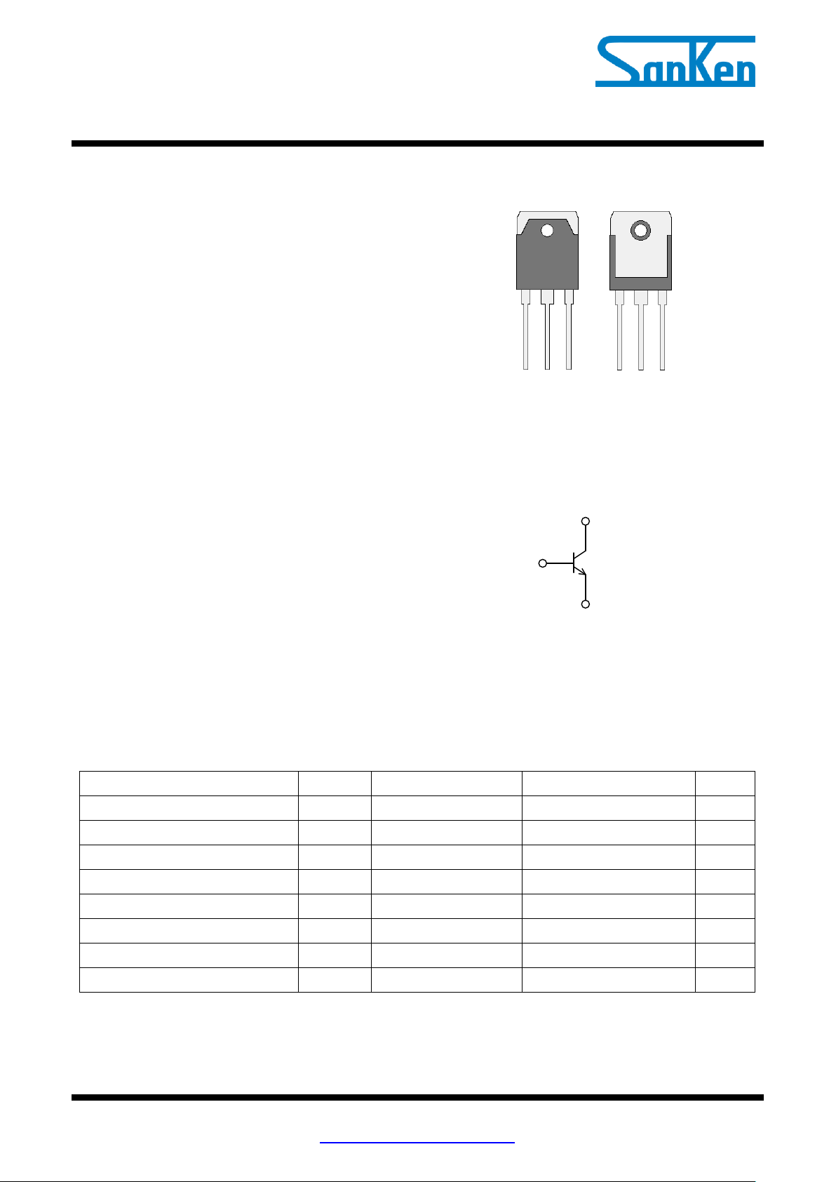
(1) (2) (3)
B C E
(4)
C
C (2)
E (3)
B (1)
http://www.sanken-ele.co.jp/en/
Silicon NPN Epitaxial Planar Bipolar Transistor
MN1526
Features
Adopt LAPT Structure
Kept hFE-IC Linearity “Flat” to High current
Improved Switching Characteristics
High Frequency
Exceptional Safe Operation Area
Complementary to MP1526
RoHS Compliant
VCE ----------------------------------------------------- 260 V
IC--------------------------------------------------------- 15 A
PC ----------------------------------------------------- 150 W
fT ----------------------------------------------- 60 MHz typ.
Applications
Power Amplifier Applications
High-End Consumer Audio Products
Professional Audio Amplifiers
SMPS
Absolute Maximum Ratings
Unless otherwise specified, T
= 25 °C
A
Package
TO-3P-3L
Not to scale
Equivalent circuit
MN1526-DS Rev.1.0 SANKEN ELECTRIC CO.,LTD. 1
Aug. 05, 2014
MN1526
Parameter
Symbol
Test Conditions
Min.
Typ.
Max.
Unit
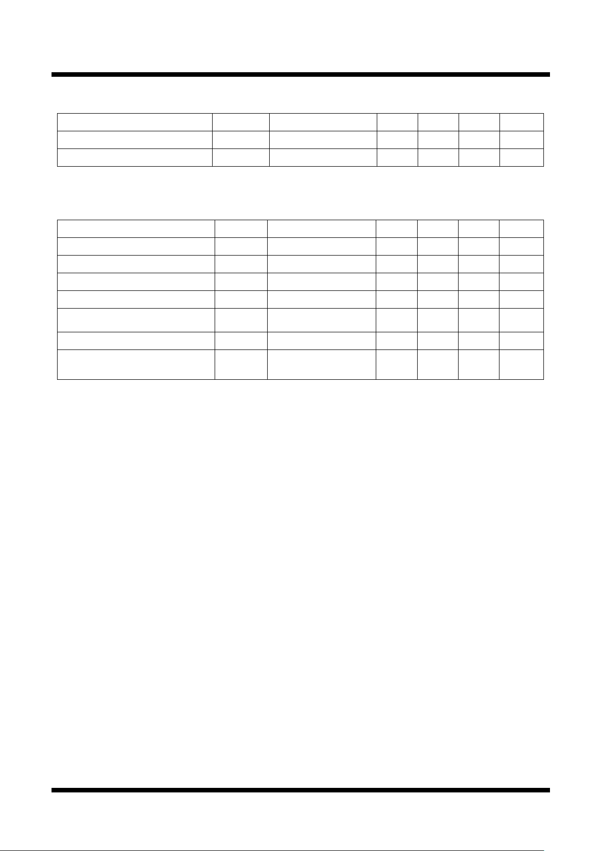
Junction to Case
R
θJC
− −
0.83
°C/W
Junction to Ambient
R
θJA
− −
35.7
°C/W
Parameter
Symbol
Test Conditions
Min.
Typ.
Max.
Unit
Collector Cut-off Current
I
CBO
V
CB
= 260 V, IE = 0 A
− − 100
µA
Emitter Cut-off Current
I
EBO
V
EB
= 5 V, IC = 0 A
− − 100
µA
Collector-Emitter Voltage
V
CEO
IC = 25 mA
260 − −
V
DC Current Transfer Ratio
hFE*
V
CE
= 4 V, IC = 5 A
40 − 140
−
Collector-Emitter Saturation
Voltage
V
CE (sat)
IC = 5 A, IB = 0.5 A
− − 2.0
V
Transition frequency
fT
V
CE
= 12 V, IE = − 2 A
−
60 − MHz
Output Capacitance
Cob
V
CB
= 10 V, f = 1 MHz,
IE = 0 A
−
250 − pF
Thermal Characteristics
Unless otherwise specified, T
Electrical Characteristics
Unless otherwise specified, T
= 25 °C
A
= 25 °C
A
*Rank of hFE : 40 to 80 (R), 50 to 100 (O), 70 to 140 (Y)
MN1526-DS Rev.1.0 SANKEN ELECTRIC CO.,LTD. 2
Aug. 05, 2014

MN1526
(1)
M N 1 5 2 6
(2) (3)
Part Number
YM A
Lot Number
Y is the Last digit of the year (0 to 9)
M is the Month (1 to 9, O, N or D)
A is the rank of hFE
(Dimensions between roots)
(Dimensions between roots)
(Dimensions between roots)
Package Outline
TO-3P-3L
NOTES:
1) Dimension is in millimeters
2) Pb-free. Device composition compliant with the RoHS directive
Marking Diagram
MN1526-DS Rev.1.0 SANKEN ELECTRIC CO.,LTD. 3
Aug. 05, 2014

MN1526
Type
Suppliers
G746
Shin-Etsu Chemical Co., Ltd.
YG6260
Momentive Performance Materials Japan LLC
SC102
Dow Corning Toray Co., Ltd.
Package
Recommended Screw Torque
TO-220, TO-220F
0.490 to 0.686 N・m (5 to 7 kgf・cm)
TO-3P, TO-3PF, TO-247
0.686 to 0.882 N・m (7 to 9 kgf・cm)
SLA
0.588 to 0.784 N・m (6 to 8 kgf・cm)
OPERATING PRECAUTIONS
In the case that you use Sanken products or design your products by using Sanken products, the reliability largely
depends on the degree of derating to be made to the rated values. Derating may be interpreted as a case that an operation
range is set by derating the load from each rated value or surge voltage or noise is considered for derating in order to
assure or improve the reliability. In general, derating factors include electric stresses such as electric voltage, electric
current, electric power etc., environmental stresses such as ambient temperature, humidity etc. and thermal stress caused
due to self-heating of semiconductor products. For these stresses, instantaneous values, maximum values and minimum
values must be taken into consideration. In addition, it should be noted that since power devices or IC’s including power
devices have large self-heating value, the degree of derating of junction temperature affects the reliability significantly.
Because reliability can be affected adversely by improper storage environments and handling methods, please
observe the following cautions.
Cautions for Storage
Ensure that storage conditions comply with the standard temperature (5 to 35°C) and the standard relative humidity
(around 40 to 75%); avoid storage locations that experience extreme changes in temperature or humidity.
Avoid locations where dust or harmful gases are present and avoid direct sunlight.
Reinspect for rust on leads and solderability of the products that have been stored for a long time.
Cautions for Testing and Handling
When tests are carried out during inspection testing and other standard test periods, protect the products from power
surges from the testing device, shorts between the product pins, and wrong connections. Ensure all test parameters are
within the ratings specified by Sanken for the products.
Remarks About Using Thermal Silicone Grease
When thermal silicone grease is used, it shall be applied evenly and thinly. If more silicone grease than required is
applied, it may produce excess stress.
The thermal silicone grease that has been stored for a long period of time may cause cracks of the greases, and it
cause low radiation performance. In addition, the old grease may cause cracks in the resin mold when screwing the
products to a heatsink.
Fully consider preventing foreign materials from entering into the thermal silicone grease. When foreign material
is immixed, radiation performance may be degraded or an insulation failure may occur due to a damaged insulating
plate.
The thermal silicone greases that are recommended for the resin molded semiconductor should be used.
Our recommended thermal silicone grease is the following, and equivalent of these.
Cautions for Mounting to a Heatsink
When the flatness around the screw hole is insufficient, such as when mounting the products to a heatsink that has
an extruded (burred) screw hole, the products can be damaged, even with a lower than recommended screw torque.
For mounting the products, the mounting surface flatness should be 0.05mm or less.
Please select suitable screws for the product shape. Do not use a flat-head machine screw because of the stress to
the products. Self-tapping screws are not recommended. When using self-tapping screws, the screw may enter the
hole diagonally, not vertically, depending on the conditions of hole before threading or the work situation. That
may stress the products and may cause failures.
Recommended screw torque:
For tightening screws, if a tightening tool (such as a driver) hits the products, the package may crack, and internal
stress fractures may occur, which shorten the lifetime of the electrical elements and can cause catastrophic failure.
Tightening with an air driver makes a substantial impact. In addition, a screw torque higher than the set torque can
MN1526-DS Rev.1.0 SANKEN ELECTRIC CO.,LTD. 4
Aug. 05, 2014

MN1526
be applied and the package may be damaged. Therefore, an electric driver is recommended.
When the package is tightened at two or more places, first pre-tighten with a lower torque at all places, then tighten
with the specified torque. When using a power driver, torque control is mandatory.
Please pay special attention about the slack of the press mold. In case that the hole diameter of the heatsink is less
than 4 mm, it may cause the resin crack at tightening.
Soldering
When soldering the products, please be sure to minimize the working time, within the following limits:
• 260 ± 5 °C 10 ± 1 s (Flow, 2 times)
• 380 ± 10 °C 3.5 ± 0.5 s (Soldering iron, 1 time)
Soldering should be at a distance of at least 1.5 mm from the body of the products.
Electrostatic Discharge
When handling the products, the operator must be grounded. Grounded wrist straps worn should have at least 1MΩ
of resistance from the operator to ground to prevent shock hazard, and it should be placed near the operator.
Workbenches where the products are handled should be grounded and be provided with conductive table and floor
mats.
When using measuring equipment such as a curve tracer, the equipment should be grounded.
When soldering the products, the head of soldering irons or the solder bath must be grounded in order to prevent
leak voltages generated by them from being applied to the products.
The products should always be stored and transported in Sanken shipping containers or conductive containers, or
be wrapped in aluminum foil.
MN1526-DS Rev.1.0 SANKEN ELECTRIC CO.,LTD. 5
Aug. 05, 2014

MN1526
IMPORTANT NOTES
The contents in this document are subject to changes, for improvement and other purposes, without notice. Make
sure that this is the latest revision of the document before use.
Application examples, operation examples and recommended examples described in this document are quoted for
the sole purpose of reference for the use of the products herein and Sanken can assume no responsibility for any
infringement of industrial property rights, intellectual property rights, life, body, property or any other rights of
Sanken or any third party which may result from its use.
Unless otherwise agreed in writing by Sanken, Sanken makes no warranties of any kind, whether express or
implied, as to the products, including product merchantability, and fitness for a particular purpose and special
environment, and the information, including its accuracy, usefulness, and reliability, included in this document.
Although Sanken undertakes to enhance the quality and reliability of its products, the occurrence of failure and
defect of semiconductor products at a certain rate is inevitable. Users of Sanken products are requested to take, at
their own risk, preventative measures including safety design of the equipment or systems against any possible
injury, death, fires or damages to the society due to device failure or malfunction.
Sanken products listed in this document are designed and intended for the use as components in general purpose
electronic equipment or apparatus (home appliances, office equipment, telecommunication equipment, measuring
equipment, etc.).
When considering the use of Sanken products in the applications where higher reliability is required (transportation
equipment and its control systems, traffic signal control systems or equipment, fire/crime alarm systems, various
safety devices, etc.), and whenever long life expectancy is required even in general purpose electronic equipment
or apparatus, please contact your nearest Sanken sales representative to discuss, prior to the use of the products
herein.
The use of Sanken products without the written consent of Sanken in the applications where extremely high
reliability is required (aerospace equipment, nuclear power control systems, life support systems, etc.) is strictly
prohibited.
When using the products specified herein by either (i) combining other products or materials therewith or (ii)
physically, chemically or otherwise processing or treating the products, please duly consider all possible risks that
may result from all such uses in advance and proceed therewith at your own responsibility.
Anti radioactive ray design is not considered for the products listed herein.
Sanken assumes no responsibility for any troubles, such as dropping products caused during transportation out of
Sanken’s distribution network.
The contents in this document must not be transcribed or copied without Sanken’s written consent.
MN1526-DS Rev.1.0 SANKEN ELECTRIC CO.,LTD. 6
Aug. 05, 2014
 Loading...