

Page 1
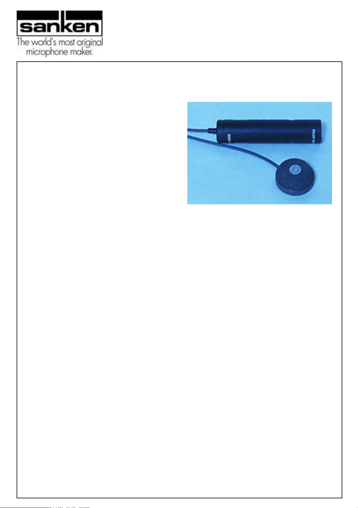
CUB-01
Miniature High-Fidelity Boundary Mic
A Totally New Concept in
Cardioid Boundary Microphones
he Sanken CUB-01 offers a totally new
design that overcomes the limitations of
T
previous boundary microphones. Generally
speaking, most boundary microphones have
almost the same sound characteristics, heard
as "thin," "solid," and "metallic." Using
Sanken's advanced technology, the CUB-01
has resolved this problem with its unique
square-shaped cardioid capsule. This
proprietary design significantly enlarges the
effective area of the diaphragm, resulting in a
boundary microphone whose sound is rich and
natural, with a flat response to 70Hz. Now it is
possible to capture a "full bodied" and "clear"
sound - Human narration and dialogue are
clearly caught while excluding unnecessary
background noise.
Sanken's revolutionary design has also
eliminated the artificial need to overdesign the
acoustic construction to create cardioid
directivity.
Engineered for use in many situations, from TV
and film field shooting to broadcast studio
production and conference table recording, the
CUB-01 departs from the common design of
the boundary mic, which typically requires a
large, heavy plate. By comparison, the CUB-01
is unbelievably small ( 32.5mm diameter,
14mm height, 45g weight ) and light. Because
of its size, it is easy to conceal from the
camera, and can be positioned in a variety of
environments, for example, attached to the
ceiling of a car with two-sided sticky tape.
The CUB-01 is available in gray or beige and in
two versions - the standard high performance
CUB-01 which runs on 48volt phantom and the
CUB-01-PT ( pigtail ) version. The PT version
will operate on 3 to 14 VDC for wireless
applications.
Theory of Boundary Microphones
There are at least two paths of sound waves
from a sound source to a microphone. One is a
direct route from the sound source ( D1 ), while
another is sound reflected on the floor between
the sound source and the microphone ( R1 ).
Obviously, sound D1 reaches to the microphone
earlier than sound R1. As a result, sound waves
through the R1 route have a "Time delay." The
sound waves through D1 and the "delayed"
sound wave (R1) will be combined at the
microphone. In this case, the delay of mid and
low frequencies will not be as affected because
of the wavelength. In case of high frequencies,
the time delay between D1 and R1 is critical
because of its short wave length. In the high
frequency range, the time delay of two sound
waves creates a cancellation between the two.
This is known as "comb filtering." When we
think about this phenomenon as rms sound
energy, we can see energy in the high frequency
range decreasing considerably when compared
to the mid and low frequencies. As frequency
increases, energy decreases.
When we place a microphone "on the floor," with
virtually no distance between the microphone
transducer and the reflecting floor surface, most
of the sound waves from the sound source to the
microphone act as one direct route. Theoretically,
there is no reflected route, and in this type of mic
positioning, there is no time delay and, therefore,
no comb filtering even in the high frequency
range. This means that sound energy in the high
frequencies is identical with the mid and lows.
This is the basic theory of a boundary
microphone.
Page 2
CUB-01
Miniature High-Fidelity Boundary Mic
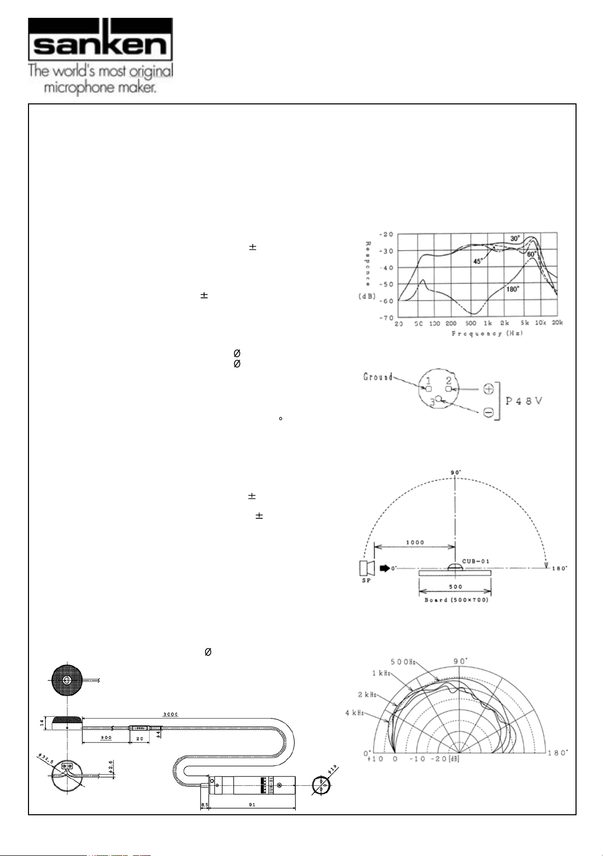
PRODUCT SPECIFICATIONS
( measurement condition; set on a board 500mm X 700mm )
1.Transducer Type
2.Directivity
3.Sensitivity
4.Frequency Response
5.Equivalent Noise Level
6.MAX. SPL
7.Output impedance
8.Required power feeding
9.Consumption current
10.OUTPUT connector
11.Directional pattern
12.Weight
13.Color
14.Dimensions
15.Cable length
16.Material
17.Finish
All specifications are measured on 500mm X 700mm board, except frequency
response. Frequency response is measured without board. (0 ON AXIS)
CUB-01-PT Specifications
(All specifications except 3,5,6,7,8,9,10,12 are same as CUB-01.
Only different parts are shown)
3.Sensitivity
5.Equivalent Noise Level
6.MAX SPL
7.Output impedance
8.Required power feeding
9.Consumption current
10.OUTPUT connector
14.Dimensions
Back electret condenser
Cardioid/front side of hemisphere
40mV(-28dB)/Pa 2dB(0dB=1V/Pa)
as attached graph
less than 16dB(A-weighted) IEC 179
122dB SPL ( THD 1%, 1kHz )
180 Ohms (1kHz)
48V 4V phantom (U.P.F)
1.8mA
XLR3-12C equivalent (1; G, 2; hot, 3; cold)
as attached drawing
45g (microphone), 55g(Phantom I/F Part)
Gray, or Beige
Microphone; 32.5mm, H 14mm
Phantom I/F; 19mm, L 91mm
3000 mm
Metal mesh Woven wire cloth
Base Copper
Fired Painted
3V power supplied
15mV(-36.5dB 2dB)/Pa (0dB=1V/Pa)
12V power supplied
16.8mV(-35.5dB 2dB)/Pa (0dB=1V/Pa)
(at 3V) less than 17dB(A-weighted) IEC 179
(at 12V) less than 16dB(A-weighted) IEC 179
3V power supplied
121 dB SPL (THD 1%, 1kHz)
12V power supplied
127 dB SPL (THD 1%, 1kHz)
120 Ohms (1kHz),
expected receive side impedance more than 5k Ohms
3V to 14V(MAX) DC
3V power supplied less than 0.6mA
12V power supplied less than 1.3mA
Pig-tail: cable direct out; hot ( signal ) white,
+DC voltage in:black, shield:ground
Microphone; 32.5mm, H 14mm
4.Frequency Response
10.Output connector
11.Directional pattern
SANKEN Microphone Co., Ltd., 2-8-8 Ogikubo, Suginami-ku, Tokyo 167-0051, Japan
Tel: +81-3-3392-6581 Fax: +81-3-3393-2055
 Loading...