

Page 1
SERVICE & OPERATING MANUAL
SERVICE & OPERATING MANUAL
SERVICE & OPERATING MANUALSERVICE & OPERATING MANUAL
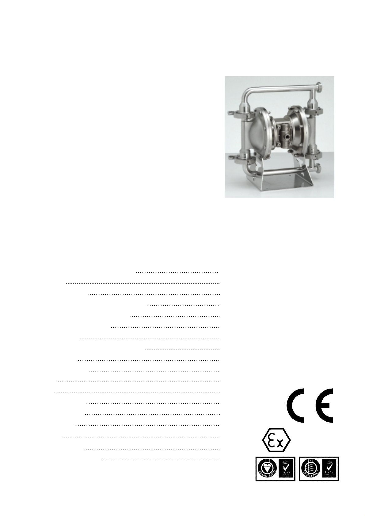
AIR OPERATED DOUBLE DIAPHRAGM PUMP
B25 & X25
B25 & X25
B25 & X25B25 & X25
Hygienic Series
Inc. Lube Free Models
This pump is Atex approved for use
in potentially explosive at mospheres
Group II category 2
Table of Contents
Service / Maintenance Log, Recycling 2
Dimensions 3
Performance Curve 3
Technical Data & Temperature limitations 4
Explanation of Pump Nomenclature 4
Principle of Pump Operation 5
Installation guide 5
Important Warnings & Safety Information 6
Troubleshooting 7
Grounding the Pump 7
Warranty 8
Service 8
Air Valve Overhaul 8
Wet-side Overhaul 8
Exhaust Safety 9
Parts List 10
Assembly Drawing 11
Declaration of Conformity 12
HG-CF-921 Rev. L - 28.07.05 Page 1
II 2 GD c
57470 31783
Page 2
Service / Maintenance Log
Date Details Completed
RECYCLING
Many components of BLAGDON ai r operated do uble diaphragm pumps are made of recyclable materials. W e encourage pum p
users to recycle worn out parts and pumps whenever possible, after any hazardous pumped fluids are thoroughly flushed.
Contact Information
Contact Phone / Fax No.
HG-CF-921 Rev. L - 28.07.05 Page 2
Page 3
GA Drawing & Performance Curve
GA Drawing & Performance Curve
GA Drawing & Performance CurveGA Drawing & Performance Curve
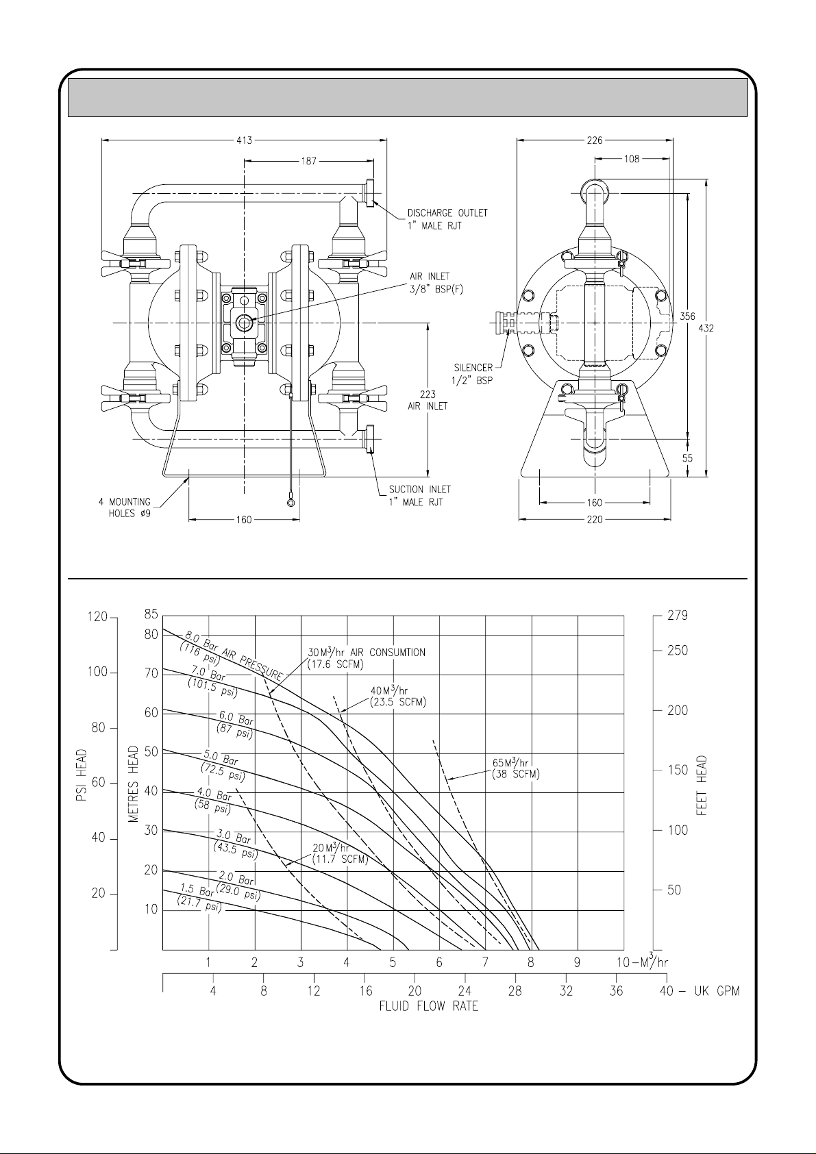
General Assembly :- B25 / X25 Hygienic Models, all dimensions +/- 2mm
B25 / X25 Hygienic Performance Curve
Performance based on water at ambient temperature
HG-CF-921 Rev. L - 28.07.05 Page 3
Page 4
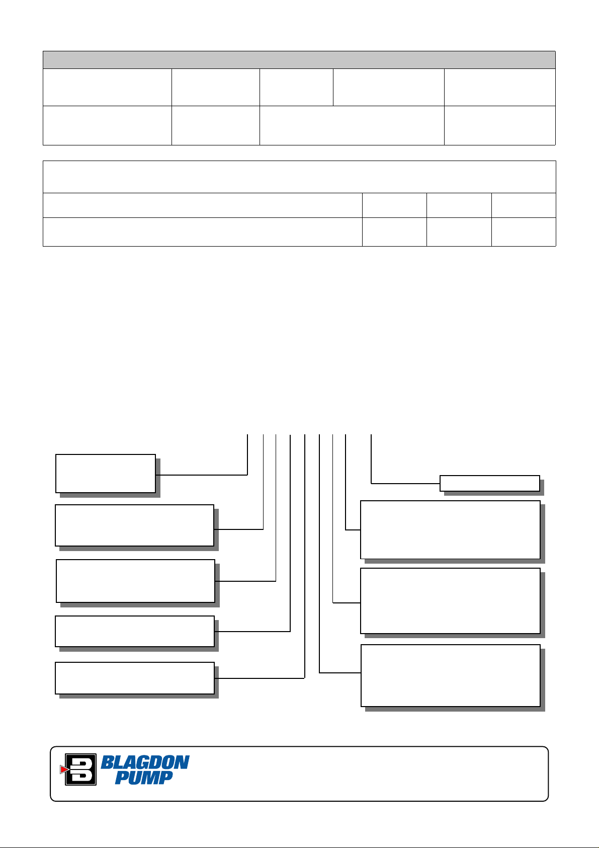
TECHNICAL DATA
FLUID CONNECTIONS CAPACITY MAX SOLIDS MAX DISCHARGE HEAD DISPLACEMENT/STROKE
1” RJT Male 0 - 136 Litres/Minute
(0 - 30 Gallons/Minute)
MAX. WORKING PRESSURE AIR INLET TEMPERATURE LIMITS PUMP WEIGHTS :-
8.6 Bar (125 psi) 3/8” BSP (F) Determined by Elastomers 21.5 Kg
5 MM
(3/16”)
88 Meters
(289 ft)
0.5 Litres
(0.11 UK Gallons)
Materials
EPDM - Shows very good water and chemical resistance. Has poor resistance to oils and solvents, but is fair on
ketones and alcohols.
Virgin PTFE - Chemically inert, virtually impervious. Very few chemicals are known to react chemically with
PTFE : molten alkali metals, turbulent liquid or gaseous fluorine and a few fluoro-chemicals such as chlorine
trifluoride or oxygen difluoride which readily liberate free fluorine at elevated temperatures.
• Gentle pumping action to avoid damage to food and
• Pressures to 8.6 bar.
beverage products.
• Capable of handling high viscosity & SG fluids.
• Range of RJT/DIN/FERRULE connections.
• Certified CIP cleanable.
• Self priming for emptying containers.
• EU Design approval
• Food grade elastomers – EPDM/PTFE
• 316L Stainless Steel
TYPICAL CODE = 25. Z F. B B. E E E - L F
Operating Temperatures
Maximum Minimum Optimum
212oF
o
100
356oF
o
180
C
C
-11oF
o
-24
32oF
o
C
0
C
50o to 212oF
o
to 100oC
10
50o to 212oF
o
to 100oC
10
MODEL
25 : STANDARD
X25 : ATEX CAT. 2
WETTED COMPONENTS
Z : 316L STAINLESS STEEL
(POLISHED)
NON - WETTED COMPONENTS
F : NICKEL PLATED ALUMINIUM
S: 316L STAINLESS STEEL
VALVE TYPE
B : BALL
SUCTION ORIENTATION
B : BOTTOM
This pump should be used in accordance with the requirements of the Health and Safety at Work Act 1974.
All business conducted subject to Blagdon Pump. Terms and Conditions of Sale, available on request.
LUBE FREE
VALVE SEATS
E : EPDM (FOOD GRADE)
S : STAINLESS STE EL
VALVE BALLS
E : FOOD GRADE EPDM
T : PTFE
S : 316 STAINLESS STEEL
DIAPHRAGMS
E : EPDM (FOOD GRADE)
O : ONE PIECE PTFE
IMPORTANT
LAMBERT ROAD,ARMSTRONG, WASHINGTON,
TYNE & WEAR NE37 1QP, ENGLAND.
TEL. : 0044 (0) 191 4177475
FAX. : 0044 (0) 191 4175435
Web Site : www.blagdonpump.com
E-Mail : sales@blagdonpump.com
HG-CF-921 Rev. L - 28.07.05 Page 4
Page 5

PRINCIPLE OF PUMP
OPERATION
This ball valve type diaphragm pump is
powered by compressed air and is a 1:1 ratio
design. The inner side of one diaphragm
chamber is alternately pressurised while
simultaneously exhausting the other inner
chamber. This causes the diaphragms, which are
connected by a common shaft secured by plates
to the centres of the diaphragms, to move in a
reciprocating action. (As one diaphragm
performs a discharge stroke the other diaphragm
is pulled to perform the suction stroke in the
opposite chamber.) Air pressure is applied over
the entire i nner surface of the di aphragm while
liquid is discharged from the opposite side of
the diaphragm. The diaphragm operates in a
balanced conditi on during the discharge stroke
which allows the pump to be operated at
discharge heads of over 200 feet (61 meters) of
water.
For maximum diaphragm life, keep the pump as
close to the liquid being pumped as possible.
Positive suction head in excess of 10 feet of
liquid (3.048 meters) may require a back
pressure regulating device to maximize
diaphragm life.
Alternate pressurising and exhausting of the
diaphragm chamber is performed by an
externally mou nted, pilot operated , 2 way type
distributi on valve. When th e spool shift s to one
end of the valve block body, inlet pressure is
applied to one chamber and the other diaphragm
chamber exha usts. When th e spool shift s to the
opposite end of the valve body, the pressure to
Lubricator
Filter/Regulater
Installation Guide
Fig. 1
the chambers is reversed. This alternating
movement of th e spool inside th e valve body is
controlled by a pilot air pressure signal held
against the diaphragm shaft, between seals in the
diaphragm shaft bushes. This signal is released,
triggering the movement of the spool, when pilot
holes in the diaphragm shaft align with the held
pilot signal, s ending the s ignal to exha ust , which
in-turn causes a pressure imbalance around the
spool, sendin g it to the op posit e end of th e valve
body. This simultaneously sends inlet pressure
to the opposite chamber.
The chambers are connect ed by manifolds with a
suction and discharge ball valve for each
chamber, maintaining flow in one direction
through the pump.
INSTALLATION
The typical installation shown in FIG. 1 is only a
guide to selecting and installing system
components. Your installation will depend on
the type of fluid being pumped and your
application needs. To reduce the risk of serious
bodily injury and damage to property, never use
fluids in this pump which are not compatible
with the wetted com ponents. Contact you r local
distributor or the manufacturer for system design
assistance & compatibility if necessary.
Mount the pump in an upri ght position. Failur e
to ensure an upright position may result in loss
of or poor priming characteristics. Ensure the
pump is securely mounted to avoid movement
and possible risk of bodily injury.
PRESSURE The pump delivers the same
pressure at the discharge outlet as the air
pressure applied at the air inlet (unless pump is
configured as a 2: 1 ra tio m o de l).
NOTE: Pressure Regulator (H) should be
installed where air supply could exceed 125
psi.
SAFETY
Your BLAGDON PUMP is a high
performance unit capable of achieving
high output s at high efficien cies. However, as
is common with pneumatic equipment, the
pump efficienc ies is reliant upon the air being
clean, dry and filtered. Failure to comply with
these requirements may lead to loss of
performance and reduced component life and in
extreme cases, permanent damage to the pump.
To avoid leaks, ensure that all fluid connections
are tight. The use of PTFE thread tape correc tly
applied should be used to ensure 100% leak
proof connections. Failure to ensure 100%
sealability of the suction connection could
adversely affect suction performance.
If you are pumping hazardous fluids, or
operating the pump in an enclosed area, it is
essential that the exhaust from the pump is
piped away to a safe location. When pumping
hazardous fluids the above instructions must be
adhered to in order to ensure safe operating
procedures. (Under certain operating
conditions the failure of internal components
can lead to the pumped fluid being exhausted
via the pump exh aust outlet).
WARNING
NEVER place your hands over or near the
pump suction inlet. Powerful suction could
cause serious bodily injury.
FLUSH THE PUMP This pump was
tested with water containing an oil-based rust
inhibitor. If thi s solution could c ontaminate or
react with the fluid you are pumping, flush the
pump thoroughly with a solvent/detergent to
clean internal components. The solvent/
detergent must be compatible with the pump
materials of con struct ion. Ca re shou ld b e taken
to flush the pump each time it is disassembled
for maintenance or repair.
CAUTION All BLAGDON PUMPS are
built lubricated with grease during assembly
and need no further lubrication. If the use of oil
cannot be avoided, this will not present any
problems. A light No. 2 class lithium grease is
recommended. Other grades may cause the Air
Logic System to op erate intermitt ently, thereby
causing a loss of ou tput and failu re to operate.
Other seals are available for “clean room”
conditions
If the pump accelerates or is running too fast
due to a lack of fluid, then stop it immediately
by shutting off the air supp ly. A dry pump will
accelerate to a high speed causing wear to
elastomers.
If the fluid you are pumping tend s to dry up or
set when it is no t moving, then flush th e pump
as often as necessary to prevent the fluid from
drying in the pump. Drain the pump thoroughly
before storing.
If feasible, invert pump to allow any fluid to
drain from the no n- r e turn valves
.
HG-CF-921 Rev. L - 28.07.05 Page 5
Page 6

Important Warnings and Safety Information
IMPORTANT
Read these safety warnings and instructions in this manual completely, before installation and start-up of the pump. It
is the responsibility of the purchaser to retain this manual for reference. This manual must be kept with, and supplied
with the pump at all times. Failure to comply with the recommendations stated in this manual will damage the pump,
and void factory warranty. These instructions are available if required, in the language or languages of the country or
countries in which the equipment is used. Please refer to the manufacturer for details.
IMPORTANT!
This pump is pr essuri zed i ntern ally wit h air pressu re du rin g ope ration . Al ways mak e certai n t hat all bol ting i s in good con ditio n and that
all of the correct bolting is reinstalled d uring assembly. End-user m ust ensure correct fitting of Inlet / Outlet con nections. Crossed
threads or over tightening of con nections will result in leaks. Quick action/release c onnections are not recommended. If thei r use is
unavoidable, the levers must be locked to avoid them being forced apart in a hazardous manner.
WARNING!
Before maintenanc e or repair, shu t off the compre ssed air line, bl eed the pre ssure, and dis connect the air l ine from the p ump. The discharge line may be press urized and must be ble d of its pre ssu re. E n d- use r m ust ensu re co rr ect r egulation of air supply pressure, as any
increase in air pressure results in a similar increase in product pressure if stalled-out.
WARNING!
Before doing any maintenance on the pump, be certain all pressure is completely vented from the pump, suction, discharge, piping, and
all other openings and connectio ns. Be certai n the air suppl y is locked o ut or made non- operational , so that it c annot be start ed while
work is being don e on the pump. B e cert ain that a pproved eye p rotection and prot ective cl othing ar e worn at all tim es in th e vicinit y of
the pump. Failure to follow these recommendations may result in serious injury or death.
WARNING!
Airborne particles and loud noise hazards. Wear ear and eye protection.
WARNING!
Take action to prevent st atic sparking. Fire or explosio n can result, especially when han dling flammable liquids. The pum p, piping,
valves, containers or other miscellaneous equipment must be grounded. Refer to exhaust safety instructions on page 9.
WARNING!
When used for toxic or ag gressive fluids, th e pump should al ways be flushed cl ean prior to disass embly. User mu st ensure chemic al
compatibility, and any pressure / temperature limits are not exceeded. These instructions include all the information for relevant
diaphragm temperature limits. Pump temperature range can also be found on data-plate attached to the pump.
If pump is not used f or m ore than 5 d ays, car e mu st be tak en whe n res tar ting . If in an y d oubt, remo ve p ump f rom li ne and fl ush wi th a
suitable cleaner. Solidified deposits within the pump may cause damage to the diaphragms.
CAUTION!
Before pump ope ration, inspect all gasketed fasteners for l ooseness caused b y gasket creep. Re-torqu e loose fasteners to prevent
leakage. Follow r ecommended torques stated in this manual. In cases of excess vibration, Blagdon recom mend fitting a Pulsation
Dampener to rem ove ef fects of pulse actions from p ump oper ation. Flexibl e connecti ons can be use d, but must b e kept t o a mi nimum
length necessary to avoid sharp flexing or straining movements
HG-CF-921 Rev. L - 28.07.05 Page 6
.
Page 7

TROUBLE SHOOTING GUIDE
NOTE :- Check all solutions before dismantling the pump.
PROBLEM CAUSE SOLUTION
Pump will not s tart Air valve assembly malfunction/Seizure
Erratic flow Diaphragm failure on one side.
Pump strokes but will not
discharge
Fluid discharged from air
exhaust
Intermitten t str oke rate Over lubrication
Obstructed fluid line.
Obstructed diaphragm chamber.
Diaphragm failure causing fluid & excessive air to be
expelled through the exhaust.
Diaphragm seal failure.
Air valve system malfunction.
Air connected to exhaust.
Valve ball not seating.
Suction leakage.
Diaphragm failure causing fluid & excessive air to be
expelled through the exhaust.
Diaphragm seal failure.
Air valve system malfunction.
Excessive suction lift.
Suction line leakage.
Valve ball not seating correctly or damaged.
Suction line or strainer clogged.
Diaphragm failure.
Diaphragm Failure.
Loose frontplate.
Diaphragm shaft seal failure.
Air valve system malfunction.
Valve ball not seating / partially obstructed.
Check carrier for freedom of movement. Clean, oil & replace.
Clean line or increase line size.
Remove obstruction.
Replace diaphragm.
Replace shaft seals.
Check all seals in valve chest assembly.
Re-connect to air inlet.
Replace diaphragm.
Check and remove obstruction.
Check and correct.
Replace diaphragm.
Replace shaft seals.
Check all seals in valve chest assembly.
Shorten suction line.
Check and correct.
Check and remove obstruction / replace.
Clear.
Replace diaphragm.
Replace diaphragm.
Re-Torque to manual specifications.
Shut-down pump. Remove air connection
into pump & introduce a small quantity of degreasing agent into air valve and replace
line. Run pump until clear.
Replace seals.
Check all seals in valve chest assembly.
Clear obstruction.
ATEX Certified units :- X25
These models are certified to :-
II 2 GD c
Non-electrical equipment for potentially explosive atmospheres,
: EN13463-1 : 2001
‘c’ - Internal control of production.
Grounding the pump :-
WARNING!
Take action to prevent static sparking. Fire or
explosion can result , especially when handling
flammable liquids. The pump, piping, valves,
containers or other miscellaneous equipment
must be grounded.
The Atex approved units are supplied with a natural earth ground
cable. This cable is 2 meters in length and permanently connected
through a nut and bolt at the inner cover casting. The other end is free
to connect to the nearest available suitable point to provide a natural
earth ground. This must be done to reduce the risk of electro-s tatic
sparking.
HG-CF-921 Rev. L - 28.07.05 Page 7
Page 8

IMPORTANT!
Read these instructions
completely, before
is the responsibility of the purchaser t o
retain this manual for reference.
Failure to comply with the
recommendations stated in this
manual will damage the pump, and
void factory warranty.
installation and start-up. It
SERVICE
The following sections give a general
overview on how to service all models of
BLAGDON Diaphragm Pumps. For
details on individual part numbers,
quantities, materials, etc., please consult
the parts list supplied with the pump.
NOTE : Before commencing any
service or maintenance work on the
pump, ensure that the air supply has
been disconnected o r isolated.
AIR VALVE SYSTEMS
PNEUMATIC TYPE Remove the 4
screws securing the valve block to the
valve chest, together with an y associated
gaskets or seals.
Remove slide valve plate & slide valve
from the valve block ass embly. Clean al l
parts thoroughly and inspect for
excessive wear, replacing where
necessary.
The slide valve and valve plate contact
faces should be flat and free from
scratches. A light polishing on a flat
surface with a fine abrasive paper will
remove most scratches.
If excessive wear is suspected in the
valve block bore or valve carrier, remove
the valve block plugs and withdraw the
valve carrier. Check valve block plug orings for wear or attack & replace where
required.
Clean the valve carrier & valve block
bore with white spirits to remove any oil
films.
NOTE : The nominal diametrica l
clearance between th e valve carrier and
the valve block bore should be 0.05 -
0.09mm. A clearance in excess of this
will cause the valve system to run
erratically.
Apply a light grease to the valve block
plug O-rings when re-assembling into the
valve block bore. Any damage to the Oring may cause the valve system to
malfunction.
Re-assemble the valve block assembly &
HG-CF-921 Rev. L - 28.07.05 Page 8
re-torque in accordance to the settings
shown in the parts list.
In the event of a complete air-side
overhaul, the pump should be disassembled down to the centre section
assembly as described later in the “WetSide Overhaul” section.
With the valve block assembly
dismantled, remove the inner covers
where appropriate.
A careful note of the position of all
related seals and gaskets should be made
to facilitate re-assembly.
Remove diaphragm shaft bushes, where
appropriate, and check all seal s and ‘O’
rings for wear or damage. If worn,
replace immediately.
NOTE:- The integrity of the diaphr agm
shaft seals is essential for the correct
functioning of all pneumatically
actuated valve systems.
Check the diaphragm shaft for e xcessive
wear as this will result in premature seal
failure. Replace as required. Lubri cate
all components and re-assemble as
detailed above, in reverse order. Ensure
the correct position of all components
detailed in all sectional assembly
drawings.
WET-SIDE OVERHAUL
REPLACING BALL VALVES
Remove discharge manifold from pump
assembly together with associated valve
balls, seats and ‘O’ rings.
NOTE :- The orientation of the val ve
seat relative to the valve ball should be
noted as incorrect positioning may
result in a performance loss.
Turn pump th rough 180
suction manifold. Clean and inspect the
components. Check for any wear or
damage and replace as required .
NOTE :- Ball or valve seat wear may
result in loss of performance and
suction lift.
Re-assemble the valve balls/seats and
ensure manifolds are adequ ately torqued
to the settings shown in the parts list.
REPLACING DIAPHRAGMS
Remove both suction and discharge
manifolds as detailed in the previous
section, removing all ball valves, seats
and ‘O’ rings.
Loosen and remove both outer covers
from the pump assembly. The
orientatio n of the covers should be noted
so as to facilitate re-assembly.
o
and remove the
Holding one of the frontplates in a vice,
(‘soft jaws’ should be fitted), or with an
adjustable spanner, loosen and remove
the frontplate from the opposite end.
Remove the diaphragm, backplate and
bumpstop from diaphragm shaft.
Carefully withdraw the diaphragm shaft
from the centre section and hold the free
end in a vice, holdin g between the flats
machined on the end. Loosen and
remove the frontplate and remove the
diaphragm together with backplate and
bumpstop (where fitted).
NOTE :- Care should be taken with all
plastic, coated and hygienic pumps, so
that the surface of the frontplate is not
damaged.
Thoroughly clean all parts and check for
wear, damage, swelling, cracking,
delamination and chemical attack.
Replace components where required.
NOTE :- Rubber diaphragms should be
replaced if they are worn to such an
extent that the fabric re-enforcing is
evident on the surface of the diaphragm.
For pumps fitted with PTFE diaphragms,
a light coating of grease should be
applied to the back-up diaphragm prior to
re-assembly.
Before re-assembly, it is advisable to
check the condition of the diaphragm
shaft seal/’O’ rings for wear or attack. If
either is evident, it is recommended that
they be replaced.
Assemble the diaphragms onto the shaft
in a reverse sequence to their removal.
Care should be taken as to the orientation
of the diaphragm relative to the front and
back plates. All diaphragms have “AIR
SIDE” moulded onto one side. The
backplate must be fitted adjacent to the
AIR SIDE of the diaphragm.
NOTE :- To achieve a leak free seal
around the clamp ba nds a plastic mallet
(A) should be used to gently tap the
clamp band into position, in a circular
manner. (Ref Fig. 2) The clamp (B)
should be tightened simultaneously
whilst using the mallet.
On all pumps fitted with stainless steel
fasteners, including clamp bands, it is
recommended that anti-seizure paste is
applied to the threads .
Bolted assemblies should be torqued to
the settings shown
in the parts list.
The manifolds
should be reassembled as
described in the
previous section.
Fig. 2
A
B
Page 9

EXHAUST SAFETY WHEN PUMPING HAZARDOUS LIQUIDS
WARNING!
In the event of diaphragm ruptu re, pum ped m ateri al m ay enter t he ai r end of t he pum p, and be disch arge d into the a tm osphere . If pum pi ng
a product which is hazardous or toxic, the air exhaust must be piped to an appropriate area for safe disposition.
Flooded Suction Installation
Suction Lift Installation
Submerged Installation
Exhaust Safety :-
When a diaphragm fails during operation, pumped liquid can enter and contaminate the air side of the pump. If diaphragm failure is not
severe, i.e. a small split or hole, then the pump can continue to run, with air being forced into the product being pumped. If however the
failure is more serious, then the pum p may stop, with fluid or fumes being expelled through the exhaust. Under these conditions it is
recommended that the exhaust is piped away to a safe area. In standard suction lift conditions this can simply be done by pi ping fr om t he
exhaust connection to a safe area. Multiple installations can be piped to a common connection, then to a safe area. In flooded suction
conditions the exhaust must be taken to a point higher than the fluid level to prevent any siphoni ng away. In submerged c onditions ens ure
exhaust is piped away above fluid level.
In all conditions ensure exhaust outlet is not expelling across a non-conductive surface. The exhaust must not be placed less than 100mm
from any non-conductive surface, as this may generate a propagating brush discharge resulting in a possible ignition sourc e.
HG-CF-921 Rev. L - 28.07.05 Page 9
Page 10

HG-CF-921 Rev. L - 28.07.05 Page 10
PARTS LIST
PARTS LIST - cont.
REF
No.
1 25-065 PUMP STAND
2 25-057 SUCTION MANIFOLD (see table for optional connections)
3 25-064 CLAMP BAND
4 SEE TABLE VALVE SEAT
5 SEE TABLE VALVE BALL
6 25-056 OUTER COVER
7 SA10403 FRONTPLATE ASSY
8 SEE TABLE DIAPHRAGM
9 25-058 DISCHARGE MANIFOLD (see table for optional connections)
10 1A259 BACKPLATE
11 1A009 BUMP STOP
12 25-059 INNER COVER
13 G242 O-RING
14 40-196 VALVE CHEST
15 25-060 DIAPHRAGM SHAFT
16 G367 O-RING
17 G245 O-RING
18 G189 O-RING
19 40-194 DIAPHRAGM SHAFT BUSH
20 G514 O-RING (See table for Lube Free Seal Option)
21 D310 SOCKET CAP SCREW
22 C173 SPRING WASHER
23 A040 BOLT
24 C044 WASHER
25 B469 NUT
26 A035 BOLT
27 G339 O-RING
28 D314 SOCKET CAP SCREW
29 G243 O-RING
30 40-204 GASKET
31 40-005 VALVE PLATE
32 40-004 SLIDE VALVE
33 H501 CIRCLIP
34 40-207 VALVE BLOCK PLUG
35 G512 O-RING
36 40-192 VALVE CARRIER
PART
NUMBER
DESCRIPTION
QTY
1
1
4
4
4
2
2
2
1
2
2
2
2
1
1
2
2
2
2
6
4
4
12
32
16
4
8
8
2
1
1
1
2
2
2
1
REF
No.
37 40-215 VALVE BLOCK
38 40-047 SILENCER (STANDARD MODELS ONLY)
39 G431 O-RING (USED WITH ST. STEEL SEATS ONLY)
38 1A377 SILENCER
40 SA10288 GROUNDING LEAD ASSY.
41 SP467 ATEX CAT.2 I/D TAG
42 SP473 TIE-LOK TIE
PART
NUMBER
THE FOLLOWING PARTS ARE USED ON ATEX CERTIFIED MODELS
DESCRIPTION
ELASTOMER TABLE
REF
No.
- These items are available in a recommended spares kit. Please refer to your local stockist / distributor for details.
- These items are available in a recommended spares kit - SA10415 - Air side Kit
Lube Free Air Side Kit :- SA10433
- These items are available as Sub-Assy. Spare :- SA10463
DESCRIPTION FOOD GRADE
4 VALVE SEAT 25-061 - 25-097 4
5 VALVE BALL 25-062 1A002 1A197 4
8 DIAPHRAGM 25-063 25-071 - 2
EPDM
PTFE STAINLESS
STEEL
QTY
LUBE FREE COMPONENTS
REF
No.
20 LUBE FREE SEAL (CENTRE SECTION) 25-072 6
CONNECTION
TYPE 1”
SUCTION MANIFOLD DISCHARGE MANIFOLD
DIN 25-112 25-113 1
FERRULE 25-115 25-116 1
IDF 25-067 1 25-068
DESCRIPTION PTFE QTY
OPTIONAL MANIFOLD PART NUMBERS
See distributors for details
QTY
NOTES
QTY
1
1
4
1
1
1
1
Page 11
HG-CF-921 Rev. L - 28.07.05 Page 11
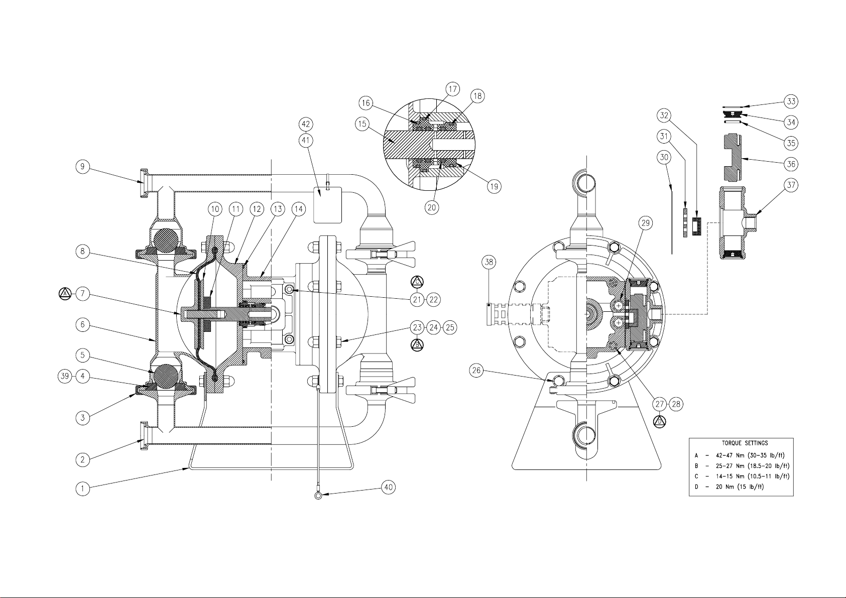
Sectional General Assembly :- B25 Hygienic Pump.
Refer to page 10, Parts List table for Item Ref. Nos.
Page 12

BLAGDON PUMP
A Unit of IDEX Corporation
Lambert Road, Armstrong,
Washington, Tyne & Wear.
NE37 1QP, England.
Tel. +44 (0) 191 4177475
Fax. +44 (0) 191 4175435
Jeff Sill,
General Manager
HG-CF-223 (REV 4)
HG-CF-921 Rev. L - 28.07.05 Page 12
 Loading...