

Page 1
SERVICE AND OPERATING MANUAL
ELECTRO-PNEUMATIC SPEED
The Warren Rupp Electro-Pneumatic Speed Control System
can be used to control SandPiper® Pumps, as well as most other
air-operated, double diaphragm pumps on the market. The Warren
Rupp Speed Control offers several benefi ts:
· Easy to Install and Operate.
· Increases Flexibility of Entire System.
· Variable Flow Rate Control.
· NEMA 4X Rated Controls.
· Manual Mode
(On-Board, Single-Turn Potentiometer).
· Or Automatic Mode
(Optional 4-20mA Input Terminal).
· Operates on 110 OR 220 VAC Power.
CONTROL SYSTEM
· Rated for maximum inlet pressures of 125 psi.
PRINCIPLE OF
OPERATION
The Warren Rupp ElectroPneumatic Speed Control System is
comprised of three components that
operate with most diaphragm pumps
to optimize operational variable fl ow
rate demands.
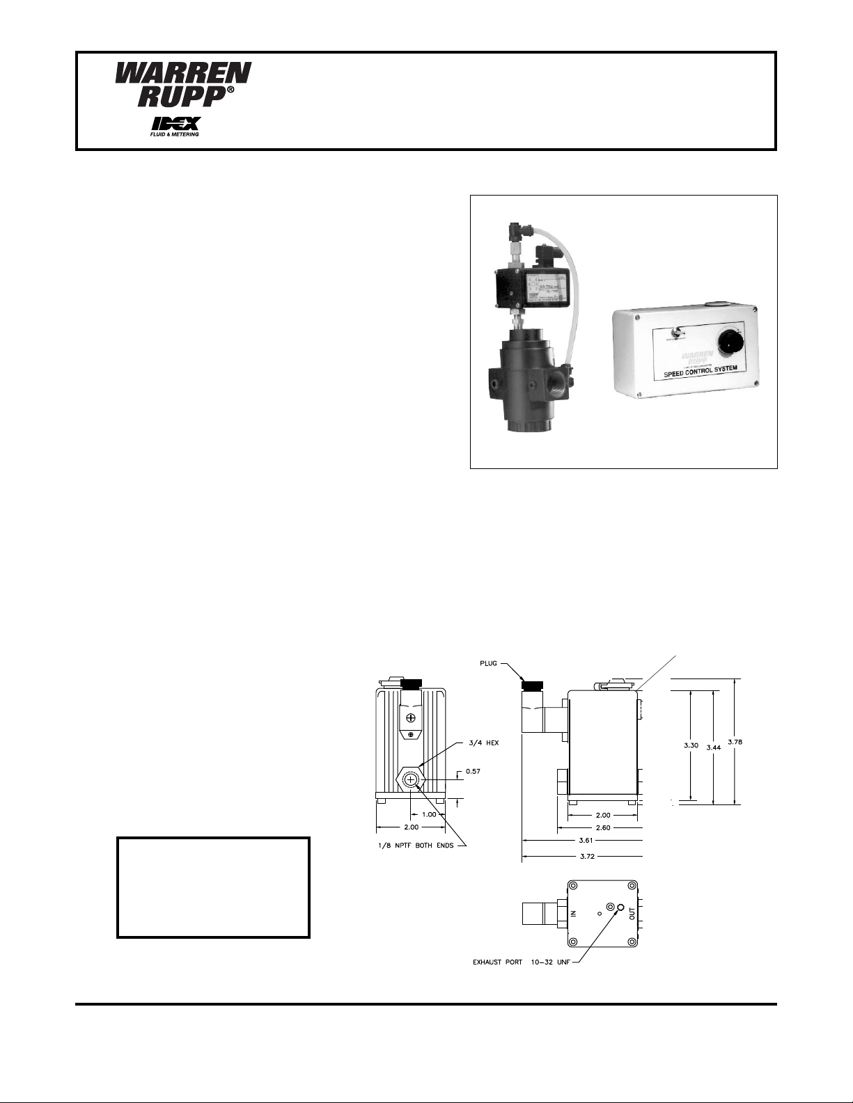
The fi rst component is an
electronically operated proportional
pilot valve that utilizes patented technology to provide extremely accurate
pneumatic control in a NEMA 4X
rated container. (See Figure 1.)
The second component is
a diaphragm, air-piloted pressure
regulator that offers higher fl ow rates
that translate into faster responses.
(See Figure 2.)
CAUTION!
Always disconnect
power before working
on units.
032-022-000 (110V)
032-023-000 (220V)
For ½ " through 4" Pumps
Pressure Regulator Port: 1"
Pilot Valve
Figure 1
WARREN RUPP, INC. • A Unit of IDEX Corporation • P.O. Box 1568 • Mansfi eld, OH 44901 USA • (419) 524-8388 Fax (419) 522- 7867
www.warrenrupp.com
spdctrol-rev0808
Speed Control Page 1
Page 2
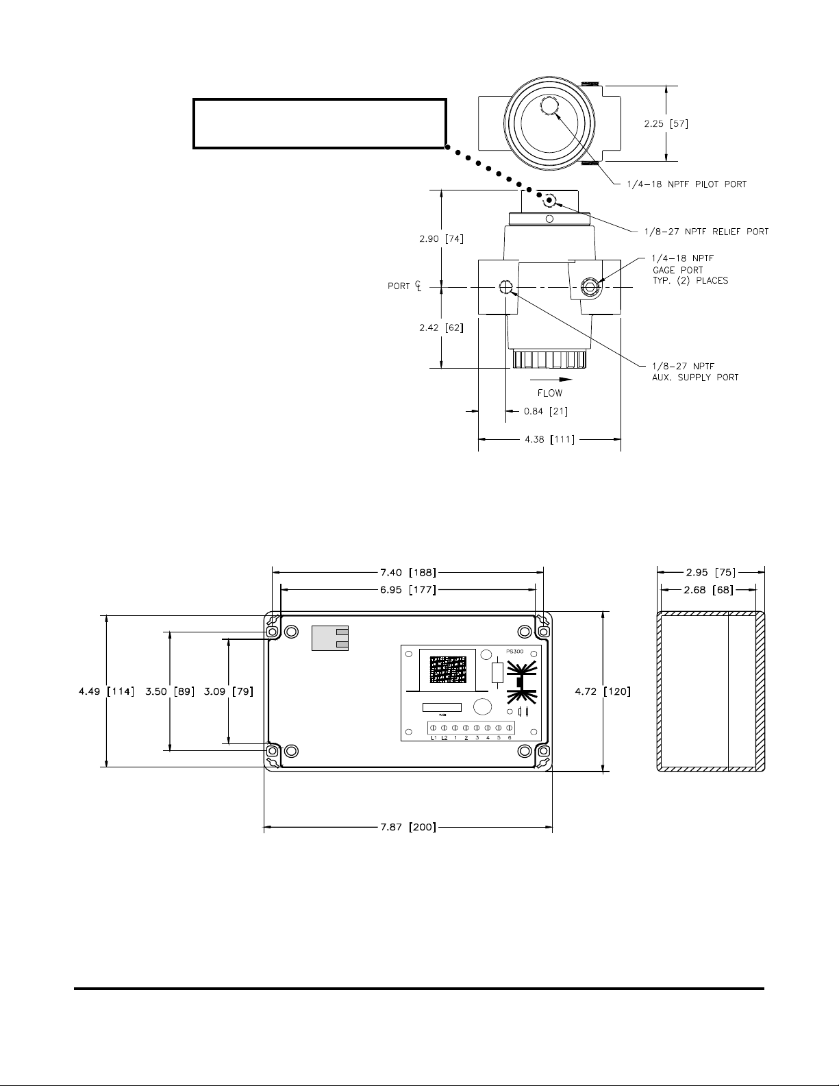
NOTE! The plug must be removed from the
relief port before operation of the unit.
The third component is the NEMA 4X rated
enclosure housing the power supply necessary
for the proportional valve as well as a control
potentiometer for manual operation. A switch on
the enclosure allows the user to select between
manual control via the provided potentiometer or
a remote control from a user supplied source,
such as a process controller supplying a 4-20
mA signal. (See Figure 3.) A 25-foot length
of electrical cable to the proportional valve is
provided. (See Installation Guide.)
1" Port Model
Figure 3
Figure 2
WARREN RUPP, INC. • A Unit of IDEX Corporation • P.O. Box 1568 • Mansfi eld, OH 44901 USA • (419) 524-8388 Fax (419) 522- 7867
www.warrenrupp.com
spdctrol-rev0808
Speed Control Page 2
Page 3

INSTALLATION & CONNECTION
Mechanical Connections: Plumb the outlet of
the air piloted regulator (procedure explained earlier) to
the inlet of the diaphragm pump. Plumb the inlet of the
air piloted regulator to the supply air. Supply air must
be clean, dry compressed air, not to exceed 125 psi.
Mount the control box in desired location.
Electrical Connections: The Warren Rupp
Speed Control System 032-022-000 is shipped
standard, set up for 110V. Speed Control System
032-023-000 is shipped standard, set up for 220V.
The units are marked accordingly on the exterior and
interior of the Power Supply Module. Be certain you
have the correct unit before installing. Connect
the AC incoming power to terminal on Power Supply
marked L1 and L2.
DO NOT USE neutral (ground) wire.
If the Warren Rupp Speed Control is to be used
as a stand-alone control device (no remote controller
used to provide command signal) the switch on the
outside of the control box ("Manual/Automatic") should
remain in the Manual position. In this scenario, any
desired changes in pressure output of the valve are
made by simply adjusting the potentiometer knob on
the face of the control panel. Clockwise turning of the
potentiometer increases the pressure speed and output. Counter clockwise movement decreases speed
and output.
NOTE: Each input volt equals 12.5 psi output
pressure. For example, at 65 psi input, the potentiometer would operate between minimum and halfway to maximum on the dial to achieve maximum
performance of this unit. (See Fig. 6).
If a remote controller is used to provide a 4-20
mA command signal, locate the small circuit board on
the inside of the face plate of the control box. Connect
4-20 + to terminal marked S+. Connect 4-20 - to terminal
marked S-. (See Figure 5.) In this scenario, when the
switch on the outside of the control box marked Manual/
Automatic is in the Manual position, the command signal is from the potentiometer on the face of the control
panel. When the switch is in the Automatic position,
the command signal comes from the 4-20 mA control
signal supplied by the remote controller.
Front View of Power Supply Module
3 amp Fuse: Replacement Part 358-001-000
Rear View of Power Supply Module
PS-300
C
A
B
D
E
Figure 4
POTENTIOMETER
MANUAL CONTROL KNOB
F
Do not exceed 125 psi input
pressure.
This setting represents
maximum performance at
approximately 65 psi input
S-
S+
Figure 5
WARREN RUPP, INC. • A Unit of IDEX Corporation • P.O. Box 1568 • Mansfi eld, OH 44901 USA • (419) 524-8388 Fax (419) 522- 7867
pressure.
Operating range of this unit
at 65 psi input pressure.
Figure 6
Maximum
Minimum
www.warrenrupp.com
spdctrol-rev0808
Speed Control Page 3
Page 4

AUTOMATIC OPERATION
This unit can be set up in the Automatic Mode for process
control (see Fig.7). In the Automatic Mode, the speed controller
will accept 4-20mA input signal to adjust the speed to meet the
application requirements.
The box is punched and plugged with contacts provided,
to accept 20-24AWG, 2-conductor cord. The input signal to the
speed control is usually generated from a programmable or
process controller which manages the overall application. There
can be numerous sensing devices used to control application
requirements, feeding signals to the programmable or process
controller. This controller then provides a 4-20mA signal to the
Warren Rupp Speed Controller, increasing or decreasing the
speed to meet demands of the application.
AUTOMATIC INSTALLATION POSSIBILITIES
Proximity Switch
or
The sensing devices might include any of the following:
1. Pump shaft proximity switch for sensing pump
speed.
2. Pressure transmitter for sensing system pressure,
suction pressure, or discharge pressure.
3. Timer.
4. Level control sensing device.
5. Flow sensing device.
6. Temperature probe.
7. Ph sensor.
8. Weight scale.
This is a partial list of possible devices.
Pressure Transducer
or
Timer
or
Level Control
or
Flow Sensor
Process
Controller
Figure 7
4-20mA
signal
AUTO
MANUAL
Speed Controller
Pump
WARREN RUPP, INC. • A Unit of IDEX Corporation • P.O. Box 1568 • Mansfi eld, OH 44901 USA • (419) 524-8388 Fax (419) 522- 7867
www.warrenrupp.com
spdctrol-rev0808
Speed Control Page 4
Page 5

IMPORTANT
Consult and follow
all local codes
and requirements
when installing this unit.
Installation Guide
NEMA 4X control box houses 110 or 220
A
VAC power supply; manual potentiometer;
and manual/automatic switch. In manual
mode, the on-board potentiometer is utilized.
In automatic mode, a remote connection
must be in place.
Part No. 032.022.000 - 110V
Part No. 032.023.000 - 220V
Power cord from control box to Electro-
B
pneumatic controller is supplied by the
manufacturer in 25' (7.62m) length. Cord is
22 AWG, 6 conductor.
For automatic mode, an optional 4-20mA
C
input signal connects here. Hole is punched
and drilled. The end-user provides remote
controller and 20-24 AWG, 2 conductor cord.
WARREN RUPP, INC. • A Unit of IDEX Corporation • P.O. Box 1568 • Mansfi eld, OH 44901 USA • (419) 524-8388 Fax (419) 522- 7867
www.warrenrupp.com
spdctrol-rev0808
Electro-pneumatic control unit. Output
D
pressure is proportional to incoming
command signal. Maximum input pressure
is 125 psi.
Diaphragm type, air-piloted pressure
E
regulator, with 1" (25.4mm) port.
Power source. 110 or 220 VAC. End-user
F
supplies 16-18 AWG, 2 conductor power
cord.
40 micron fi ltration is recommended.
G
Speed Control Page 5
 Loading...