

Page 1

SanDisk
Product Manual
Version 3.1
Document No. 80-36-00450
December 2006
SanDisk Corporation
Corporate Headquarters • 601 McCarthy Boulevard • Milpitas, CA 95035
Phone (408) 801-1000 • Fax (408) 801-8657
www.sandisk.com
Page 2

Revision 3.1 SanDisk iNAND Product Manual
®
SanDisk
Corporation general policy does not recommend the use of its products in life support applications where in a failure
or malfunction of the product may directly threaten life or injury. Per SanDisk Terms and Conditions of Sale, the user of SanDisk
products in life support applications assumes all risk of such use and indemnifies SanDisk against all damages. See “Disclaimer
of Liability.”
This document is for information use only and is subject to change without prior notice. SanDisk Corporation assumes no
responsibility for any errors that may appear in this document, nor for incidental or consequential damages resulting from the
furnishing, performance or use of this material. No part of this document may be reproduced, transmitted, transcribed, stored in
a retrievable manner or translated into any language or computer language, in any form or by any means, electronic,
mechanical, magnetic, optical, chemical, manual or otherwise, without the prior written consent of an officer of SanDisk
Corporation.
All parts of the SanDisk documentation are protected by copyright law and all rights are reserved.
SanDisk and the SanDisk logo are registered trademarks of SanDisk Corporation. CompactFlash is a U.S. registered trademark
of SanDisk Corporation.
Product names mentioned herein are for identification purposes only and may be trademarks and/or registered trademarks of
their respective companies.
© 2006 SanDisk Corporation. All rights reserved.
SanDisk products are covered or licensed under one or more of the following U.S. Patent Nos. 5,070,032; 5,095,344; 5,168,465;
5,172,338; 5,198,380; 5,200,959; 5,268,318; 5,268,870; 5,272,669; 5,418,752; 5,602,987. Other U.S. and foreign patents
awarded and pending.
Lit. No. 80-36-00450 Rev. 3.1 12/06 Printed in U.S.A.
Revision History
September 2005 Revision 0.1—First draft of initial release
October 2005 Revision 0.2—Second draft of initial release
October 2005 Revision 0.3—Third draft of initial release
October 2005 Revision 1.0—Release
November 2005 Revision 1.1—Minor revision in Section 1.2; changed area in Table 1-1
January 2006 Revision 2.0—Added 4GB specifications
February 2006 Revision 2.1—Added footnote for MB/GB calculation in Section 2, 3 & App B
November 2006 Revision 3.0—Major revision to include high capacity information and other changes to the SDA spec;
updated contact information.
December 2006 Revision 3.1—Changed G8 pin from “VCORE” to “FCAP”; adjusted capacitor specifications.
© 2006 SanDisk Corporation i
Page 3

Revision 3.1 SanDisk iNAND Product Manual
TABLE OF CONTENTS
1. Introduction...................................................................................................1-1
1.1 General Description................................................................................1-1
1.2 Features...................................................................................................1-2
1.3 Document Scope.....................................................................................1-2
1.4 iNAND Standard ....................................................................................1-2
1.5 Functional Description............................................................................1-3
1.6 Technology Independence ......................................................................1-3
1.7 Defect and Error Management................................................................1-4
1.8 Wear Leveling.........................................................................................1-4
1.9 Automatic Sleep Mode ...........................................................................1-4
1.10 iNAND—SD Bus Mode........................................................................1-4
1.11 SPI Mode...............................................................................................1-6
2. Product Specifications...................................................................................2-1
2.1 Overview ................................................................................................2-1
2.2 Typical Card Power Requirements .........................................................2-1
2.3 System Performance...............................................................................2-1
2.4 System Reliability and Maintenance ......................................................2-1
2.5 Physical Specifications...........................................................................2-2
2.6 Capacity Specifications ..........................................................................2-4
3. iNAND Interface Description .......................................................................3-1
3.1 Pins and Registers...................................................................................3-1
3.2 Bus Topologies.......................................................................................3-2
3.3 Electrical Interface..................................................................................3-3
3.4 iNAND Registers....................................................................................3-3
3.5 Data Interchange Format and Card Sizes ...............................................3-3
4. iNAND Protocol Description........................................................................4-1
4.1 General ...................................................................................................4-1
4.2 SD Bus Protocol.....................................................................................4-1
4.3 Functional Description............................................................................4-1
Appendix A Capacitor Specifications..........................................................A-1
Appendix B Ordering Information..............................................................B-1
Appendix C SanDisk Worldwide Sales Offices........................................... C-1
Appendix D Limited Warrant y....................................................................D-1
Appendix E Disclaimer of Liability.............................................................E-1
© 2006 SanDisk Corporation ii
Page 4
Chapter 1 – Introduction
Revision 3.1 SanDisk iNAND Product Manual
1 Introduction
1.1 General Description
The SanDisk iNAND is a very small, flash storage device, designed specifically for storage
applications that put a premium on small form factor, low power and low cost. Flash is the
ideal storage medium for portable, battery-powered devices. It features low power
consumption and is non-volatile, requiring no power to maintain the stored data. It also has
a wide operating range for temperature, shock and vibration.
iNAND is well-suited to meet the needs of small, low power, electronic devices. With a
form factor measuring 12mm by 18mm by 1.2mm, iNAND is expected to be used in a wide
variety of portable devices like mobile phones, pagers, and voice recorders.
To support this wide range of applications, iNAND is offered with an SD Interface. T he SD
interface product is fully compatible with iNAND produc ts, and provides a 4-bit data bus
for maximum performance. For compatibility with existing controllers, the iNAND offers,
in addition to these interfaces, an alternate communication-protocol based on the SPI
standard.
These interfaces allow for easy integration into any design, regardless of which type of
microprocessor is used. All device and interface configuration data (such as maximum
frequency and card identification) are stored on the device.
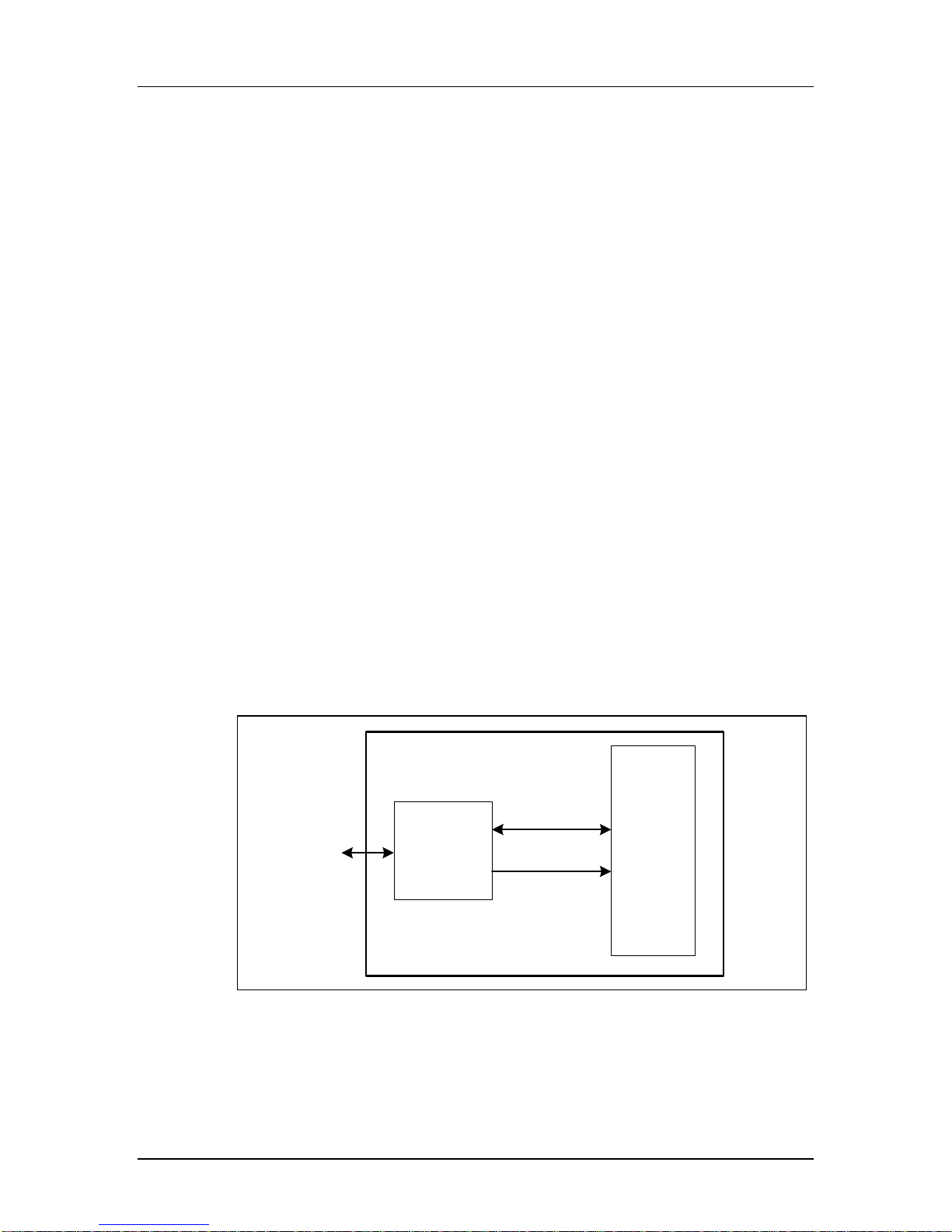
The SanDisk iNAND provides up to 4 GB of memory for use in mass storage applications.
In addition to the mass-storage-specific flash memory chip, iNAND includes an intelligent
controller, which manages interface protocols, data storage and retrieval, error correction
code (ECC) algorithms, defect handling and diagnostics, power management, wear
leveling, and clock control. Figure 1-1 is a block diagram of the SanDisk iNAND with SD
Interface.
Figure 1-1 SanDisk iNAND Block Diagram
SanDisk iNAND
SD Bus/SPI Bus
Interface
SanDisk
Single Chip
Controller
Data In/Out
Control
Flash
Memory
© 2006 SanDisk Corporation 1-1 12/07/06
Page 5

Chapter 1 – Introduction
Revision 3.1 SanDisk iNAND Product Manual
1.2 Features
SanDisk iNAND product features include the following.
►Up to 4 GB of data storage
►SD-protocol compatible
►Supports SPI Mode
►Designed for portable and stationary applications that require high performance and reliable
data storage
►Voltage range 2.7 to 3.6V
Variable clock rate 0-25 MHz (default), 0-50MHz (high-speed)
►
► Up to 25 MB/sec bus transfer rate (using 4 parallel data lines)
►Correction of memory-field errors
►Built-in write protection features (permanent and temporary)
►Application-specific commands
►Standard footprint across all capacities
1.3 Document Scope
This document describes the key features and specifications of the SanDisk iNAND as well
as the information required to interface it to a host system. Chapter 2 describes the physical
and mechanical properties of iNAND, Chapter 3 contains the pins and register overview,
and Chapter 4 gives a general overview of the SD protocol. Information about SPI Protocol
can be referenced in Section 7 of the SDA Physical Layer Specification, Version 2.00.
1.4 iNAND Standard
SanDisk iNAND devices are fully compatible with the SDA Physical Layer Specification,
Version 2.00. This specification is available from the SD Card Association (SDA).
SD Card Associations
2400 Camino Ramon, Suite 37 5
San Ramon, CA 94583 USA
T elephone: +1 (925) 275-6615
Fax: +1 (925) 886-4870
E-mail: office@sdcard.org
Website:
www.sdcard.org
© 2006 SanDisk Corporation 1-2 12/07/06
Page 6

Chapter 1 – Introduction
Revision 3.1 SanDisk iNAND Product Manual
1.5 Functional Description
The SanDisk iNAND contains a high-level, intelligent subsystem as shown in Figure 1-1.
This intelligent (microprocessor) subsystem provides many capabilities not found in other
types of memory cards. These capabilities include:
• Host independence from details of erasing and programming flash memory
• Sophisticated system for managing defects (analogous to systems found in magnetic
disk drives)
• Sophisticated system for error recovery including a powerful ECC
• Power management for low power operation
1.6 Technology Independence
The 512-byte sector size of the SanDisk iNAND is the same as that in an IDE magnetic
disk drive. To write or read a sector (or multiple sectors), the host software simply issues a
read or write command to the card. The command contains the address and number of
sectors to write or read. The host software then waits for the command to complete.
The host software does not get involved in the details of how the flash memory is erased,
programmed or read. This is extremely important because flash devices are expected to get
increasingly complex in the future. Because iNAND use an intelligent on-board controller,
host system software will not need to be updated as new flash memory evolves. In other
words, systems that support iNAND technology today will be able to access future SanDisk
devices built with new flash technology without having to update or change host software.
© 2006 SanDisk Corporation 1-3 12/07/06
Page 7

Chapter 1 – Introduction
Revision 3.1 SanDisk iNAND Product Manual
1.7 Defect and Error Management
The SanDisk iNAND contains a sophisticated defect and error management system. This
system is analogous to the systems found in magnetic disk drives and in many cases offers
enhancements. If necessary, iNAND will rewrite data from a defective sector to a good
sector. This is completely transparent to the host and does not consume any user data space.
The soft error rate specification for iNAND is much better than the magnetic disk drive
specification. In the extremely rare case that a read error does occur, iNAND has
innovative algorithms to recover the data. These defect and error management systems,
coupled with the solid state construction, give SanDisk iNAND unparalleled reliability.
1.8 Wear Leveling
Wear-leveling is an intrinsic part of the erase pooling functionality of iNAND.
1.9 Automatic Sleep Mode
A unique feature of iNAND is automatic entrance and exit from sleep mode. Upon
completion of an operation, cards enter sleep mode to conserve power if no further
commands are received in less than 5 milliseconds (ms). The host does not have to take any
action for this to occur. However, in order to achieve the lowest sleep current, the host
needs to shut down its clock to the card. In most systems, cards are in sleep mode except
when accessed by the host, thus conserving power.
When the host is ready to access a card in sleep mode, any command issued to it will cause
it to exit sleep, and respond.
1.10 iNAND — SD Bus Mode
The following sections provide valuable information on SanDisk iNAND in SD Bus mode.
SanDisk iNAND devices are fully compliant with the SDA Physical Layer Specification,
Version 2.00. Card Specific Data (CSD) Register structures are compliant with CSD
Structure 1.0 and 2.0.
This section covers Negotiating Operating Conditions, Card Acquisition and Identification,
Card Status, Memory Array Partitioning, Read/Write Operations, Data Transfer Rate, Data
Protection in Flash Cards, Write Protection, Copy Bit, and CSD Register.
Additional practical card detection methods can be found in application notes pertaining to
the SDA Physical Layer Specification, Version 2.00.
© 2006 SanDisk Corporation 1-4 12/07/06
Page 8
Chapter 1 – Introduction
Revision 3.1 SanDisk iNAND Product Manual
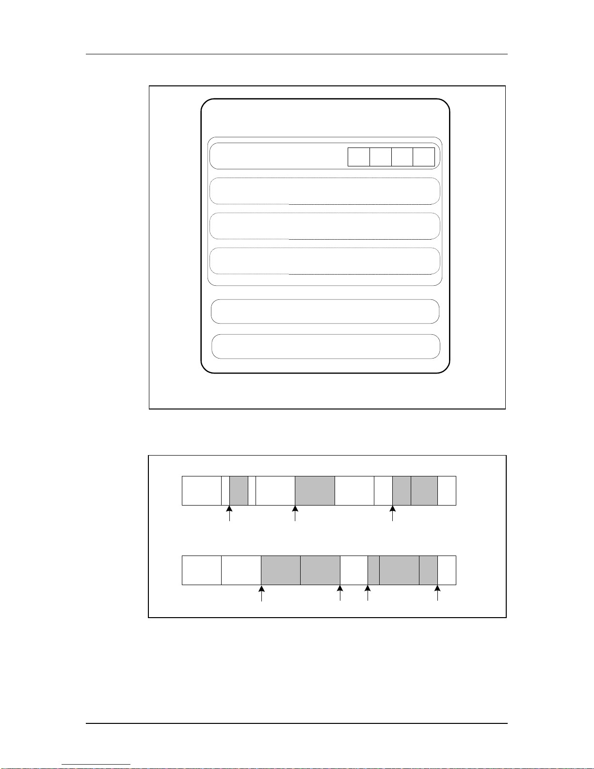
Figure 1-2 Memory Array Parti tioni n g
SanDisk iNAND Memory Module
WP Group 0
Sector 1
Block
Block1Block2Block
0
n
Sector 2
Sector 3
Sector n
WP Group 1
WP Group 2
Figure 1-3 Data Transfer Formats
Single Block Mode
Memory
Sectors
Memory
Sectors
Start Address
(Read)
Memory
Sectors
Start Address
Memory
Sectors
(Write)
Multiple Block Mode
Memory
Sectors
Memory
Sectors
Memory
Sectors
Start Address
Memory
Sectors
Write
Memory
Sectors
Memory
Sectors
Stop Start
Misalignment Error
Memory
Sectors
Start Address
(Read/Write)
Memory
Sectors
Read
Memory
Sectors
Memory
Sectors
Stop
© 2006 SanDisk Corporation 1-5 12/07/06
Page 9

Chapter 1 – Introduction
Revision 3.1 SanDisk iNAND Product Manual
Table 1-1 Mode Definitions
Mode Description
Single Block In this mode the host reads or writes one data block in a pre-specified length. The
Multiple Block This mode is similar to the single block mode, except for the host can read/write
data block transmission is protected with 16-bit CRC that is generated by the
sending unit and checked by the receiving unit.
The block length for read operations is limited by the device sector size (512 bytes)
but can be as small as a single byte. Misalignment is not allowed. Every data block
must be contained in a single physical sector.
The block length for write operations must be identical to the sector size and the
start address aligned to a sector boundary.
multiple data blocks (all have the same length) that are stored or retrieved from
contiguous memory addresses starting at the address specified in the command.
The operation is terminated with a stop transmission command.
Misalignment and block length restrictions apply to multiple blocks and are identical
to the single block read/write operations.
1.11 SPI Mode
The SPI Mode is a secondary communication protocol for iNAND devices. This mode is a
subset of the SD Protocol, designed to communicate with an SPI channel, commonly found
in Motorola and other vendors’ microcontrollers. Table 1-1 contains names and
descriptions of SPI Mode functions. More information about SPI Mode can be found in
Section 7 or the SDA Physical Layer Specification, Version 2.00.
© 2006 SanDisk Corporation 1-6 12/07/06
Page 10

Chapter 2 – Product Specifications
Revision 3.1 SanDisk iNAND Product Manual
2 Product Specifications
2.1 Overview
For details about the environmental, reliability and durability specifications, refer to
Section 8.1 of the SDA Physical Layer Specification, Version 2.00.
2.2 Typical Card Power Requirements
Table 2-1 iNAND Power Requirements (Ta=25°C@3.0V)
VDD (ripple: max, 60mV peak-to-peak) 2.7 V – 3.6 V
Value Measurement Average
Sleep 250 uA Max
Read 100 mA Max
Write 100 mA Max
2.3 System Performance
All performance values for iNAND in Table 2-2 were measured using the following
conditions:
• Voltage range 2.7 V to 3.6 V
• Temperature -25° C to 85° C
• Independent of the iNAND clock frequency
Table 2-2 System Performance
Timing Maximum Value
Block Read Access Time
Block Write Access Time
CMD1 to Ready after Power-up 1000 ms
2.4 System Reliability and Maintenance
Ta ble 2-3 Reliability and Maintenance Specifications
MTBF >1,000,000 hours
Preventative Maintenance None
Data Reliability <1 non-recoverable error in 1014 bits read
100 ms
250 ms
© 2006 SanDisk Corporation 2-1 12/07/06
Page 11

Chapter 2 – Product Specifications
Revision 3.1 SanDisk iNAND Product Manual
2.5 Physical Specifications
The SanDisk iNAND is a 56-pin, thin fine-pitched ball grid array (BGA). See Figure 2-1
(56-pin) for physical specifications and dimensions. See Figure 2-2 for a top view of the
pin definitions.
Figure 2-1 iNAND Specifications (18 x 12mm Package)
Top View
Bottom View
© 2006 SanDisk Corporation 2-2 12/07/06
Page 12

Chapter 2 – Product Specifications
Revision 3.1 SanDisk iNAND Product Manual
Table 2-4 iNAND Package Specifications (18 x 12mm Package)
Dimension in millimeters Dimension in inches
Symbol Minimum Nominal Maximum Minimum Nominal Maximum
A --- --- 1.20 or 1.40 --- --- 0.047
A1 0.30 0.35 0.38 0.012 0.014 0.015
A2 0.69 0.74 0.79 0.027 0.029 0.031
D 17.90 18.00 18.10 0.705 0.709 0.713
E 11.90 12.00 12.10 0.469 0.472 0.476
D1 --- 7.00 --- --- 0.276 --D2 --- 11.00 --- --- 0.433 --D3 --- 13.00 --- --- 0.512 --E1 --- 7.00 --- --- 0.276 ---
e --- 1.00 --- --- 0.039 ---
b 0.45 0.50 0.55 0.018 0.020 0.022
aaa 0.10 0.004
bbb 0.10 0.004
ddd 0.15 0.006
eee 0.25 0.010
fff 0.10 0.004
MD/ME 12/11 12/11
Figure 2-2 iNAND Ball Array (Top View)
G8
FCAP
H6
H7
GND
G7
VDDG6DAT2G5CSB_DAT3
H5DUH4DUH3DUH2
VDD
G4
CMD
G3
DAT1
GND
G2
DAT0
G1
CLK
F2
F7
F8
DU
DU
E8
DU
DU
E7
DU
VDD
E2DUE1
F1
DU
B3
VDD
A3
DU
D2DUD1
C2DUC1
B2
DU
A2
VDD
GND
VDD
B1
GND
D7
D8
DU
DU
C8
C7
DU
DU
B8
B7DUB6DUB5
DU
A7
GNDA6VDDA5DU
VDD
B4
VDD
A4
DU
DU = Don't use
Pin A1 ID
© 2006 SanDisk Corporation 2-3 12/07/06
Page 13

Chapter 2 – Product Specifications
Revision 3.1 SanDisk iNAND Product Manual
2.6 Capacity Specifications
Table 2-5 Model Capacity Summary*
Model No. Capacity
SDINB1-256 256 MB
SDINB1-512 512 MB
SDINB1-1024 1024 MB
SDINB1-2048 2048 MB
SDINB1-4096 4096 MB
* 1 megabyte (MB) = 1 million bytes; 1 gigabyte (GB) = 1 billion bytes. Some of the listed capacity is used for
formatting and other functions, and thus is not available for data storage.
© 2006 SanDisk Corporation 2-4 12/07/06
Page 14

Chapter 3 – iNAND Interface Description
Revision 3.1 SanDisk iNAND Product Manual
3 iNAND Interface Description
3.1 Pins and Registers
Table 3-1 contains the SanDisk iNAND functional ball assignment
Table 3-1 iNAND Pin Assignment
Pin No. Name Type1 Description Comment
SD Bus Mode
H6, F1, C1,
A2, A6
H7, H2, D1,
B1, A7
G2 DAT0 I/O Data Line [Bit 0]
G3 DAT1 I/O Data Line [Bit 1]
G6 DAT2 I/O Data Line [Bit 2]
G5 DAT3 I/O Data Line [Bit 3]
G1 CLK I Clock
G4 CMD I/O Command/Response
B5 WPB I Defines I/F Connect to
G7 RSTB I Defines I/F Connect to
B2 RDY/BSY NC
B3 SEL_A I Defines I/F Connect to
B4 SEL_B I Defines I/F Connect to
G8 FCAP -- Grounded filter capacitor
SPI Mode
VDD S Supply Voltage
VSS S Supply Voltage Ground
VDD
VDD
VDD
VDD
H6, F1, C1,
A2, A6
H7, H2, D1,
B1, A7
G2 DataOut I/O Device to Host Data and Status
G3 DAT1 I/O Unused Pull up to VDD
G6 DAT2 I/O Unused Pull up to VDD
G5 CS I Chip Select (Active low)
G1 CLK I Clock
G4 DataIn I Host to Device Commands and
© 2006 SanDisk Corporation 3-1 12/07/06
1
Type Key: S=power supply; I=input; O=output using push-pull drivers; PP=I/O using push-pull drivers
VDD S Supply Voltage
VSS S Supply Voltage Ground
Data
Page 15

Chapter 3 – iNAND Interface Description
Revision 3.1 SanDisk iNAND Product Manual
Pin No. Name Type1 Description Comment
B5 WPB I Write Protect (Active low) Connect to
G7 RSTB I Reset (Active low) Connect to
B2 RDY/BSY NC
VDD
VDD
B3 SEL_A I Defines I/F Connect to
B4 SEL_B I Defines I/F Connect to
G8 FCAP -- Grounded filter capacitor
SanDisk iNAND contains a set of information registers. Register descriptions and SDA
references are provided in Section 5.0 of the SDA Physical Layer Specification, Version
2.00.
Table 3-2 iNAND Register Overview
Register Abbreviation Width (in bits) Register Name
CID 128 Card Identification Number
RCA 16 Relative Card Address
CSD 128 Card Specific Data
SCR 64 SD Configuration
OCR 32 Operation Conditions
SSR 512 SD Status
CSR 32 Card status; information about the card status.
3.2 Bus Topologies
VDD
VDD
SanDisk iNAND products support two communication protocols: SD and SPI. For more
details, refer to Section 3.5 of the SDA Physical Layer Specification, Version 2.00. Section
6 of the specification contains a bus circuitry diagram for reference.
3.2.1 SD Bus
For more details, refer to Secti on 3. 5.1 of the SDA Physical Layer Specification, Version
2.00.
3.2.2 SPI Bus
For more details, refer to Secti on 3. 5.2 of the SDA Physical Layer Specification, Version
2.00.
© 2006 SanDisk Corporation 3-2 12/07/06
Page 16

Chapter 3 – iNAND Interface Description
Revision 3.1 SanDisk iNAND Product Manual
3.3 Electrical Interface
The power scheme of SanDisk iNAND is handled locally in each card and in the bus
master. Refer to Section 6.4 of the SDA Physical Layer Specification, Version 2.00.
3.3.1 Power Up
Refer to Section 6.4.1 of the SDA Physical Layer Specification, Version 2.00.
3.3.2 Bus Operating Conditions
SPI Mode bus operating conditions are identical to SD Bus Mode operating conditions. For
details, see Section 6.6 of the SDA Physical Layer Specification, Version 2.00.
3.3.3 Bus Timing (Default)
See Section 6.7 of the SDA Physical Layer Specification, Version 2.00.
3.3.4 Bus Timing (High-Speed Mode)
See Section 6.8 of the SDA Physical Layer Specification, V ersion 2.00.
3.4 iNAND Registers
There is a set of eight registers within the iNAND interface. For specific information about
each register, refer to Section 5 of the SDA Physical Layer Specification, Version 2.00.
3.4.1 Operating Conditions Register
The Operation Conditions Register (OCR) stores the VDD voltage profile for iNAND.
Refer to Section 5.1 of the SDA Physical Layer Specification, Version 2.00.
3.4.2 Card Identification Register
The Card Identification (CID) Register is 16 bytes long and contains the unique card
identification number. It is programmed during manufacturing and cannot be changed by
iNAND hosts. See Table 3-3.
© 2006 SanDisk Corporation 3-3 12/07/06
Page 17

Chapter 3 – iNAND Interface Description
(
Revision 3.1 SanDisk iNAND Product Manual
Table 3-3 CID Register Definitions
Name Type Width CID Value Comments
Manufacturer ID
(MID)
OEM/Application ID
(OID)
Product Name
(PNM)
Product Revision
(PRV)
Serial Number
(PSN)
Binary 8 0x03 Manufacturer IDs are controlled and
ASCII 16 SD ASCII Code
ASCII 40
BCD 8 Product
Binary 32 Product Serial
0x53, 0x44
ST04G
ST02G
ST01G
ST512
ST256
Revision xx
Number
assigned by the SD-3C, LLC
Identifies the card OEM and/or the card
contents. The OID is controlled and
assigned by the SD-3C, LLC
Five ASCII characters long
See Section 5.2 in the SDA Physical
Layer Specification, Version 2.00
32-bit unsigned integer
Reserved --- 4 --- --Manufacture Date
Code (MDT)
CRC7 checksum
CRC)
Not used, always --- 1 --- ---
Note: SD-3C, LLC is a limited liability company established by Matsushita Electric Industrial Co. Ltd.,
SanDisk Corporation and Toshiba Corporation.
*The CRC checksum is computed by using the following formula: CRC Calculation: G(x)
7+x3
= x
+1
M(x)=(MID-MSB)*x
CRC[6…0]=Remainder[(M(x)*x
BCD 12 Manufacture
Binary 7 CRC7* Calculated
119
+…+(CIN-LSB)*x0
7
)/G(x)]
date (for ex.
April 2001=
0x014)
Manufacturing date—yym (offset from
2000)
© 2006 SanDisk Corporation 3-4 12/07/06
Page 18

Chapter 3 – iNAND Interface Description
Revision 3.1 SanDisk iNAND Product Manual
3.4.3 Card Specific Data Regis ter
The Card Specific Data (CSD) Register configuration information is required to access
iNAND data. The CSD defines the data format, error correction type, maximum data
access time, etc. The field structures of the CSD Register vary depending on the physical
specifications and card capacity. The CSD_STRUCTURE field in the CSD Register
indicates which structure version is used. Table 3-4 shows the version number as it relates
to the CSD structure. Refer to Section 5.3.1 of the SDA Physical Layer Specification,
Version 2.00 for more information.
Table 3-4 CSD Register S tructures
CSD_STRUCTURE CSD Structure Version Valid for SD Memory Card Physical
1 CSD Version 2.0 Version 2.00 / High Capacity
2-3 Reserved ---
Specification Version / Card Capacity
Version 1.01 to 1.10 0 CSD Version 1.0
Version 2.00 / Standard Capacity
Table 3-5 provides an overview of the CSD Register. More field-specific information can
be found in Section 5.3.2, Table 5-4 of the SDA Physical Layer Specification, Version 2.00.
Table 3-5 CSD Register (CSD Version 1.0)
Field CSD Value Description
CSD_ STRUCTURE 1.0 CSD structure
--- --- Reserved
TAAC
NSAC 0 Data read access time-2 in CLK cycles
CCC All (inc. WP,
READ_BL_ LEN 2G
READ_BL_ PARTIAL Yes Partial blocks for read allowed
WRITE_BLK_ MISALIGN No Write block misalignment
READ_BLK_ MISALIGN No Read block misalignment
DSR_IMP No DSR implemented
--- --- Reserved
C_SIZE 2 GB
VDD_R_ CURR_MIN 100 mA Max. read current @VDD min.
VDD_R_ CURR_MAX 80 mA Max. read current @VDD max.
1.5 msec Data read access time-1
(NSAC*100)
Default 25MHz TRANS_ SPEED
High-speed 50MHz
lock/unlock)
Up to 1G
1 GB
512 MB
256 MB
Max. data transfer rate
Card command classes
Max. read data block length
Device size
© 2006 SanDisk Corporation 3-5 12/07/06
Page 19

Chapter 3 – iNAND Interface Description
Revision 3.1 SanDisk iNAND Product Manual
Field CSD Value Description
VDD_W_ CURR_MIN 100 mA Max. write current @VDD min.
VDD_W_ CURR_MAX 80 mA Max. write current @VDD max.
C_SIZE_ MULT 2G=2048
1G=1024
512=512
256=256
ERASE_BLK_EN Yes Erase single block enable
SECTOR_ SIZE 32 blocks Erase sector size
WP_GRP_ SIZE 128 sectors Write protect group size
WP_GRP_ ENABLE Yes Write protect group enable
Reserved --- Reserved for MMC compatibility
R2W_ FACTOR x16 Write speed factor
Device size multiplier
WRITE_BL_ LEN 2G
WRITE_BL PARTIAL No Partial blocks for write allowed
--- --- Reserved
FILE_ FORMAT_ GRP 0 File format group
COPY Has been copied Copy flag (OTP)
PERM_ WRITE_
PROTECT
TMP_WRITE_PROTECT Not protected Temporary write protection
FILE_ FORMAT HD w/partition File format
Reserved --- Reserved
CRC CRC7 CRC
--- --- Not used, always “1”
Up to 1G
Not protected Permanent write protection
Max. write data block length
© 2006 SanDisk Corporation 3-6 12/07/06
Page 20

Chapter 3 – iNAND Interface Description
Revision 3.1 SanDisk iNAND Product Manual
Refer to Section 5.3.3, Table 5-16 of the SDA Physica l Layer Specification, Version 2.00
for more detailed information.
Table 3-6 CSD Register (CSD Version 2.0)
Field CSD Value Description
CSD_ STRUCTURE 2.0 CSD structure
--- --- Reserved
TAAC
NSAC 0 Data read access time-2 in CLK cycles
CCC 010110110101b All
READ_BL_ LEN --- Max. read data block length
1.5 ms Data read access time-1
(NSAC*100)
Default 25MHz TRANS_ SPEED
High-speed 50MHz
(inc. WP,
lock/unlock)
Max. data transfer rate
Card command classes
READ_BL_ PARTIAL Yes Partial blocks for read allowed
WRITE_BLK_ MISALIGN No Write block misalignment
READ_BLK_ MISALIGN No Read block misalignment
DSR_IMP No DSR implemented
--- 0 Reserved
C_SIZE
--- 0 Reserved
ERASE_BLK_EN 1 Erase single block enable
SECTOR_ SIZE 32 blocks Erase sector size
WP_GRP_ SIZE 128 sectors Write protect group size
WP_GRP_ ENABLE Yes Write protect group enable
Reserved --- Reserved for MMC compatibility
R2W_ FACTOR x16 Write speed factor
WRITE_BL_ LEN --- Max. write data block length
WRITE_BL PARTIAL No Partial blocks for write allowed
--- --- Reserved
FILE_ FORMAT_ GRP 0 File format group
COPY Has been copied Copy flag (OTP)
PERM_ WRITE_
PROTECT
32 GB
16 GB
8 GB
4 GB
Not protected Permanent write protection
Device size
© 2006 SanDisk Corporation 3-7 12/07/06
Page 21

Chapter 3 – iNAND Interface Description
Revision 3.1 SanDisk iNAND Product Manual
Field CSD Value Description
TMP_WRITE_PROTECT No protected Temporary write protection
FILE_ FORMAT HD w/partition File format
Reserved --- Reserved
CRC CRC7 CRC
--- --- Not used, always “1”
3.4.4 Card Status Register
The Card Status Register (CSR) transmits the card’s status information (which may be
stored in a local status register) to the host. The CSR is defined in Section 4.10.1 in the
SDA Physical Layer Specification, Version 2.00.
3.4.5 SD Status Register
The SD Status Register (SSR) contains status bits that are related to iNAND proprietary
features and may be used for future applications. The SD Status structure is described in
Section 4.10.2 in the SDA Physical Layer Specification, Version 2.00.
3.4.6 Relative Card Address Register
The 16-bit Relative Card Ad dress (RCA) Register carries the card address published by
the card during the card identification. Refer to Section 5.4 in the SDA Physical Layer
Specification, Version 2.00 for more information.
3.4.7 SD Card Configuration Register
The SD Card Configuration Register (SCR) is in addition to the CSD Register. The SCR
provides information about special features in SanDisk iNAND. For more information,
refer to Section 5.6 in the SDA Physical Layer Specification, Version 2.00.
3.4.8 SD Card Registers in SPI Mode
All registers are accessible in SPI Mode. Their format is identical to the format in the SD
Bus Mode, however a few fields are irrelevant in SPI Mode. In SPI Mode, the Card Status
Register has a different, shorter, format as well. Refer to Section 7. 4 in the SDA Physical
Layer Specification, Version 2.00. for more details.
3.5 Data Interchange Format and Card Sizes
In general, a file system provides structure for iNAND data. The SD Card File System
Specification, published by the SD Association, describes the file format system
implemented in the SanDisk iNAND.
© 2006 SanDisk Corporation 3-8 12/07/06
Page 22

Chapter 3 – iNAND Interface Description
Revision 3.1 SanDisk iNAND Product Manual
Table 3-7 User Area DOS Image Parameters
Capacity* Total
LBAs
4 GB 8,027,136 8192 8,018,944 8,012,708 4,102,506,496
2 GB 4,013,056 523 4,011,595 4,011,072 2,053,668,864
1 GB 2,006,528 523 2,005,675 2,005,152 1,026,637,824
512 MB 1,003,264 279 1,002,727 1,002,448 513,253,376
256 MB 501,632 157 501,149 500,992 256,507,904
Number of
Partition
System Area
Sectors
Total Partition
Sectors
User Data
Sectors
User Data
Bytes
1 megabyte (MB) = 1 million bytes; 1 gigabyte (GB) = 1 billion bytes. Some of the listed capacity is used
*
for formatting and other functions, and thus is not available for data storage.
© 2006 SanDisk Corporation 3-9 12/07/06
Page 23

Chapter 4 – iNAND Protocol Description
Revision 3.1 SanDisk iNAND Product Manual
4 iNAND Protocol Description
4.1 General
iNAND protocol information is contained in this chapter; information includes bus
protocol, card identification, and a functional description.
4.2 SD Bus Protocol
Communication over the SD bus is based on command and data-bit streams in itiated by a
start bit and terminated by a stop bit. See Section 3.6.1 of the SDA Physical Layer
Specification, Version 2.00 for details.
4.3 Functional Description
The host controls all communication between itself and iNAND. To demonstrate how this
communication works, this section provides a general overview of the card identification
and data transfer modes; commands; card dependencies; various card operation modes and
restrictions for controlling the clock signal. All iNAND commands, together with
corresponding responses, state transitions, error conditions, and timin gs are also provided.
For detailed information, refer to Section 4 of the SDA Physical Layer Specification,
Version 2.00.
4.3.1 Card Identification Mode
In Card Identification Mode the host resets all cards, validates operation voltage range,
identifies and requests cards to publish a relative card address. For more information see
Section 4.2 in the SDA Physical Layer Specification, Version 2.00.
4.3.2 Data Transfer Mode
In Data Transfer Mode, the host may operate iNAND in the f
section contains information about data read and write, erase, write protect management,
card lock/unlock operations, application-specific commands, the switch function command,
high-speed mode, the command system, the Send Interface Condition command (CMD8).
CMD8 is part of identification mode and command functional differences in high capacity
iNAND. For more detailed information, refer to Section 4.3 of the SDA Physical Layer
Specification, Version 2.00.
4.3.3 Clock Control
The host can use the bus clock signal in iNAND to switch them to energy saving mode or
to control data flow on the bus. See Section 4.4 of the SDA Physical Layer Specification,
Version 2.00.
frequency range. This
PP
© 2006 SanDisk Corporation 4-1 12/07/06
Page 24

Chapter 4 – iNAND Protocol Description
Revision 3.1 SanDisk iNAND Product Manual
4.3.4 Cyclic Redundancy Codes
The Cyclic Redundancy Check (CRC) protects against transmission errors that may occur
on the iNAND bus. Detailed information and examples for CRC7 and CRC16 are provided
in Section 4.5 of the SDA Physical Layer Specification, Version 2.00.
4.3.5 Error Conditions
See Section 4.6 of the SDA Physical Layer Specification, Version 2.00.
4.3.6 Commands
See Section 4.7 of the SDA Physical Layer Specification, Version 2.00 for detailed
information about iNAND commands.
4.3.7 Card State Transition
The state transition is dependent on the received command. The transition is defined in
Section 4.8 of the SDA Physical Layer Specification, Version 2.00 along with responses
sent on the command line.
4.3.8 Timing Diagrams and Values
See Section 4.12 of the SDA Physical Layer Specification, Version 2.00.
4.3.9 Speed Class Specification
The speed class specification classifies card performance by speed class number and offers
the method to calculate performance. For more information, refer to Section 4.13 of the
SDA Physical Layer Specification, Version 2.00.
4.3.10 Erase Timeout Calculation
See Section 4.14 of the SDA Physical Layer Specification, Version 2.00.
© 2006 SanDisk Corporation 4-2 12/07/06
Page 25

Appendix A –Capacitor Specifications
Revision 3.1 SanDisk iNAND Product Manual
Appendix A Capacitor Specifications
A.1 SanDisk iNAND Operation
In order for iNAND to operate at 3V, an external capacitor must be added to the FCAP
(G8) pin and grounded to VSS. The capacitor’s specifications and its placement
instructions are detailed below.
The trace requirements from the FCAP (G8) pin to the capacitor are as follows:
• Resistance: <2 ohm
• Inductance: <5 nH
The capacitor requirements are as follows:
• Capacitance: >=2.2uF
• Voltage: >=6.3 V
• Dielectric: X7R or X5R
Trace
C1=C3>=2.2uF
C2=C4<=100nF
C1, C2: X7R or XR5
Close to ball F1
F1
VDD
G8
FCAP
Requirements:
Resistance < 2 ohm
Inductance < 5 nH
C1
VSS
C2
VSS
C1=C3>=2.2uF
C2=C4<=100nF
C3, C4: X7R or XR5
Close to ball A 6
Bottom View
A6
VDD
VSS
C3
VSS
C4
VSS
Capacitor
Requirements:
Capacitance > = 2.2uF
Voltage > =6.3V
Dielectric X7R or XR5
© 2006 SanDisk Corporation A-1 12/07/06
Page 26

Appendix B –Ordering Information
Revision 3.1 SanDisk iNAND Product Manual
Appendix B Ordering Information
B.1 iNAND
To order SanDisk products directly from SanDisk, call (408) 801-1000.
Part Number Block Size1
SDINB1-256 256 MB
SDINB1-512 512 MB
SDINB1-1024 1024 MB
SDINB1-2048 2048 MB
SDINB1-4096 4096 MB
© 2006 SanDisk Corporation B-1 12/07/06
1
1 megabyte (MB) = 1 million bytes; 1 gigabyte (GB) = 1 billion bytes. Some of the listed capacity is used for
formatting and other functions, and thus is not available for data storage.
Page 27

Appendix C –SanDisk Worldwide Sales Offices
Revision 3.1 SanDisk iNAND Product Manual
Appendix C SanDisk Worldwide Sales Offices
To order SanDisk products directly from SanDisk, call (408) 801-1000.
SanDisk Corporate Headquarters
601 McCarthy Blvd.
Milpitas, CA 95035
Tel: 408-801-1000
Fax: 408-801-8657
http://www.sandisk.com
U.S. OEM Sales Offices
Southwest/Northwest USA & Mexico
601 McCarthy Blvd.
Milpitas, CA 95035
Tel: 408-801-1000
Fax: 408-801-8657
Northeastern USA/Canada
620 Herndon Pkwy. Suite 200
Herndon, VA 22070
Tel: 703-481-9828
Fax: 703-437-9215
International OEM Sales Offices
Europe
SanDisk GmbH
Karlsruher Str. 2C
D-30519 Hannover, Germany
Tel: 49-511-875-9131
Fax: 49-511-875-9187
Northern/Central/Southern Europe
Rudolf-Diesel-Str. 3
40822 Mettmann, Germany
Tel: 49-210-495-3433
Fax: 49-210-495-3434
Japan
8F Nisso Bldg. 15
2-17-19 Shin-Yokohama,
Kohoku-ku
Yokohama 222-0033,
Japan
Tel: 81-45-474-0181
Fax: 81-45-474-0371
Asia/Pacific Rim
Suite 902-903
Bank of East Asia Harbour View Centre
56 Gloucester Road
Wanchai Hong Kong
Tel: 852-2712-0501
Fax: 852-2712-9385
© 2006 SanDisk Corporation C-1 12/07/06
Page 28

Appendix D –Limited Warranty
Revision 3.1 SanDisk iNAND Product Manual
Appendix D Limited Warranty
I. WARRANTY STATEMENT
SanDisk warrants its products to be free of any defects in materials or workmanship that would
prevent them from functioning properly for one year from the date of purchase. This express
warranty is extended by SanDisk Corporation.
II. GENERAL PROVISIONS
This warranty sets forth the full extent of SanDisk’s responsibilities regarding the SanDisk iNAND.
In satisfaction of its obligations hereunder, SanDisk, at its sole option, will repair, replace or refund
the purchase price of the product.
NOTWITHSTANDING ANYTHING ELSE IN THIS LIMITED WARRANTY OR OTHERWISE,
THE EXPRESS WARRANTIES AND OBLIGATIONS OF SELLER AS SET FORTH IN THIS
LIMITED WARRANTY, ARE IN LIEU OF, AND BUYER EXPRESSLY WAIVES ALL OTHER
OBLIGATIONS, GUARANTIES AND WARRANTIES OF ANY KIND, WHETHER EXPRESS
OR IMPLIED, INCLUDING WITHOUT LIMITATION, ANY IMPLIED WARRANTY OF
MERCHANTABILITY OR FITNESS FOR A PARTICULAR PURPOSE OR INFRINGEMENT,
TOGETHER WITH ANY LIABILITY OF SELLER UNDER ANY CONTRACT, NEGLIGENCE,
STRICT LIABILITY OR OTHER LEGAL OR EQUITABLE THEORY FOR LOSS OF USE,
REVENUE, OR PROFIT OR OTHER INCIDENTAL OR CONSEQUENTIAL DAMAGES,
INCLUDING WITHOUT LIMITATION PHYSICAL INJURY OR DEATH, PROPERTY
DAMAGE, LOST DATA, OR COSTS OF PROCUREMENT OF SUBSTITUTE GOODS,
TECHNOLOGY OR SERVICES. IN NO EVENT SHALL THE SELLER BE LIABLE FOR
DAMAGES IN EXCESS OF THE PURCHASE PRICE OF THE PRODUCT, ARISING OUT OF
THE USE OR INABILITY TO USE SUCH PRODUCT, TO THE FULL EXTENT SUCH MAY BE
DISCLAIMED BY LAW.
SanDisk’s products are not warranted to operate without failure. Accordingly, in any use of products
in life support systems or other applications where failure could cause injury or loss of life, the
products should only be incorporated in systems designed with appropriate redundancy, fault tolerant
or back-up features.
III. WHAT T HIS WARRANTY COVERS
For products found to be defective within one year of purchase, SanDisk will have the option of
repairing or replacing the defective product, if the following conditions are met:
A. A warranty registration card for each defective product was submitted and is on file
at SanDisk. If not, a warranty registration card must accompany each returned
defective product. This card is included in each product’s original retail package.
B. The defective product is returned to SanDisk for failure analysis as soon as possible
after the failure occurs.
C. An incident card filled out by the user, explaining the conditions of usage and the
nature of the failure, accompanies each returned defective product.
D. No evidence is found of abuse or operation of products not in accordance with the
published specifications, or of exceeding storage or maximum ratings or operating
conditions.
All failing products returned to SanDisk under the provisions of this limited warranty shall be tested
to the product’s functional and performance specifications. Upon confirmation of failure, each
product will be analyzed, by whatever means necessary, to determine the root cause of failure. If the
© 2006 SanDisk Corporation D-1 12/07/06
Page 29

Appendix D –Limited Warranty
Revision 3.1 SanDisk iNAND Product Manual
root cause of failure is found to be not covered by the above provisions, then the product will be
returned to the customer with a report indicating why the failure was not covered under the warranty.
This warranty does not cover defects, malfunctions, performance failures or damages to the unit
resulting from use in other than its normal and customary manner, misuse, accident or neglect; or
improper alterations or repairs.
SanDisk reserves the right to repair or replace, at its discretion, any product returned by its
customers, even if such product is not covered under warranty, but is under no obligation to do so.
SanDisk may, at its discretion, ship repaired or rebuilt products identified in the same way as new
products, provided such cards meet or exceed the same published specifications as new products.
Concurrently, SanDisk also reserves the right to market any products, whether new, repaired, or
rebuilt, under different specifications and product designations if such products do not meet the
original product’s specifications.
IV. RECEIVING WARRANTY SERVICE
According to SanDisk’s warranty procedure, defective product should be returned only with prior
authorization from SanDisk Corporation. Please contact SanDisk’s Customer Service department at
408-801-1000 with the following information: product model number and description, serial
numbers, nature of defect, conditions of use, proof of purchase and purchase date. If approved,
SanDisk will issue a Return Material Authorization or Product Repair Au thorization number. Ship
the defective product to:
SanDisk Corporation
Attn: RMA Returns
(Reference RMA or PRA #)
601 McCarthy Boulevard
Milpitas, CA 95035
V. STATE LAW RIGHTS
SOME STATES DO NOT ALLOW THE EXCLUSION OR LIMITATION OF INCIDENTAL OR
CONSEQUENTIAL DAMAGES, OR LIMITATION ON HOW LONG AN IMPLIED
WARRANTY LASTS, SO THE ABOVE LIMITATIONS OR EXCLUSIONS MAY NOT APPLY
TO YOU. This warranty gives you specific rights and you may also have other rights that vary from
state to state.
© 2006 SanDisk Corporation D-2 12/07/06
Page 30

Appendix E –Disclaimer of Liability
Revision 3.1 SanDisk iNAND Product Manual
Appendix E Disclaimer of Liability
E.1 SanDisk Corporation Policy
SanDisk Corporation general policy does not recommend the use of its products in life
support applications wherein a failure or malfunction of the product may directly threaten
life or injury. Accordingly, in any use of products in life support systems or other
applications where failure could cause damage, injury or loss of life, the products should
only be incorporated in systems designed with appropriate redundancy, fault tolerant or
back-up features.
SanDisk shall not be liable for any loss, injury or damage caused by use of the Products in
any of the following applications:
− Special applications such as military related equipment, nuclear reactor control, and
aerospace
− Control devices for automotive vehicles, train, ship and traffic equipment
− Safety system for disaster prevention and crime prevention
− Medical-related equipment including medical measurement device
© 2006 SanDisk Corporation E-1 12/07/06
 Loading...