


Warning
RF Exposure Warning :
The radiated output power of this device is below the FCC radio frequency exposure limits. Nevertheless, the device should be used in such a manner that the potential for human contact during normal operation is minimized. In order to avoid the possibility of exceeding the FCC radio frequency exposure limit, human proximity to the
antenna should not be less than 6 feet during normal operation.
Information to user
The user’s manual or instruction manual for an intentional or unintentional radiator shall caution the user that changes or modifications not expressly approved by the party responsible for compliance could void the user's authority to operate the equipment. In cases where the manual is provided only in a form other than paper, such as on a computer disk or over the Internet, the information required by this section may be included in the manual in that alternative form, provided the user can reasonably be expected to have the capability to access information in that form.

Contents
SRG-3150DN Rev.1.1(080409)
SRG-3150DN How to operate basic function and Distress transmitting |
|
1. Set MMSI ID................................................................................................................. |
5 |
1.1. Self-ID........................................................................................................ |
5 |
2. SSB mode....................................................................................................................... |
5 |
2.1. Channel Selection................................................................................ |
5 |
2.2. Frequency Selection............................................................................ |
5 |
2.3. TX, RX........................................................................................................ |
5 |
3. DSC mode...................................................................................................................... |
5 |
3.1. Channel Selection................................................................................ |
5 |
3.2. Frequency Selection............................................................................ |
5 |
3.3. Call.............................................................................................................. |
6 |
3.4. DSC Message RX Auto Reply......................................................... |
6 |
4. Distress transmit......................................................................................................... |
6 |
How to use SN-100 NBDP Terminal |
|
1. Selection of Channel................................................................................................. |
6 |
2. Selection of Frequency............................................................................................ |
6 |
3. ARQ mode..................................................................................................................... |
6 |
4. FEC mode....................................................................................................................... |
6 |
Chapter 1. Overview ............................................................................................................. |
7 |
1.1. Features....................................................................................................................... |
7 |
1.2. Basic Components.................................................................................................. |
8 |
Chapter 2. Specifications..................................................................................................... |
9 |
2.1. General specification............................................................................................. |
9 |
2.2. MF/HF Transmitter.................................................................................................. |
9 |
2.3. MF/HF Receiver........................................................................................................ |
9 |
2.4. DSC (Digital Selective Calling) W/K Receiver .......................................... |
10 |
2.5. MF/HF Control....................................................................................................... |
10 |
2.6. Digital Selective Calling (DSC)........................................................................ |
10 |
2.7. Narrow band direct Printing (NBDP)........................................................... |
11 |
2.8. Printer (DPU-414).................................................................................................. |
11 |
2.9. Printer (OKI)............................................................................................................. |
11 |
Chapter 3. Power Supply ................................................................................................... |
12 |
3.1. Power On.................................................................................................................. |
12 |
3.2. Operation by AC power..................................................................................... |
12 |
3.3. Operation by DC (BATTERY) power.............................................................. |
12 |
3.4. BATTERY Charging................................................................................................ |
12 |
Chapter 4. Front Panel ....................................................................................................... |
13 |
4.1. About Button, Knob, Lamp.............................................................................. |
13 |
4.2. LCD display.............................................................................................................. |
14 |
4.3. LCD display flow.................................................................................................... |
15 |
Chapter 5. SSB (TEL) mode............................................................................................... |
16 |
5.1. SSB Mode................................................................................................................. |
16 |
5.2. SSB Menu................................................................................................................. |
16 |
(1) Scan Type Set........................................................................................ |
16 |
(2) Scan Channel Set................................................................................. |
16 |
(3) Scan Frequency Set............................................................................. |
16 |
|
1 |

(4) |
SQL Set..................................................................................................... |
16 |
(5) |
LCD Contrast Set.................................................................................. |
17 |
(6) Tx Power Set........................................................................................... |
17 |
|
(7) |
Manual Tuning....................................................................................... |
17 |
(8) |
ATU – Version (ATU Program Version)....................................... |
17 |
(9) |
Remote Set ............................................................................................. |
17 |
(10) System Set............................................................................................ |
17 |
|
5.3. Additional Functions (ITU Channel, AM mode, Etc.,)........................... |
18 |
|
Chapter 6. Digital selective calling (DSC) mode.............................................................. |
19 |
|
6.1. The selection of DSC mode............................................................................. |
19 |
|
6.2. DSC menu display................................................................................................ |
19 |
|
(1) |
Distress msg edit ................................................................................. |
19 |
(2) |
Individual msg edit............................................................................. |
20 |
(3) |
Group msg edit..................................................................................... |
21 |
(4) |
Geography msg edit ....................................................................... |
22 |
(5) |
Auto/Semi-AT msg edit .................................................................... |
25 |
(6) |
Dist ack/rly msg edit.......................................................................... |
26 |
(7) |
Ordinary ack msg edit....................................................................... |
28 |
(8) |
Display and print msg....................................................................... |
28 |
(9) |
System Set............................................................................................... |
28 |
Chapter 7. Transmitter of distress signal......................................................................... |
32 |
|
7.1. Test of Distress alert signal.............................................................................. |
32 |
|
Chapter 8. RX of Distress & general call.......................................................................... |
33 |
|
8.1. RX of Distress Alarm........................................................................................... |
33 |
|
8.2. General call RX....................................................................................................... |
34 |
|
Chapter 9. How to use print............................................................................................... |
|
35 |
9.1. DPU-414 Printer.................................................................................................... |
35 |
|
9.2. OKI Printer................................................................................................................ |
35 |
|
Chapter 10. How to use SD-250(Alarm box) .................................................................... |
36 |
|
10.1. Distress transmitting......................................................................................... |
36 |
|
10.2. In case of receiving distress signal............................................................ |
36 |
|
10.3. Operation by DC (Battery)............................................................................. |
36 |
|
Chapter 11. How to use SP-1250ADC ............................................................................... |
36 |
|
11.1. Specification......................................................................................................... |
36 |
|
11.2. Input power shift................................................................................................ |
36 |
|
11.3. How to Charge.................................................................................................... |
36 |
|
11.4. In case of over current.................................................................................... |
36 |
|
Chapter 12. Circuit explain ................................................................................................ |
|
37 |
12.1. Overview of SRG-3150DN.............................................................................. |
37 |
|
12.2. CONTROL CIRCUIT (T-1110)......................................................................... |
38 |
|
(1) |
MF/HF RX Circuit.................................................................................. |
38 |
(2) |
MF/HF TX Circuit.................................................................................. |
38 |
(3) |
Local Synthesizer Circuit................................................................... |
39 |
(4) |
Power Supply Circuit.......................................................................... |
39 |
(5) |
Control Circuit....................................................................................... |
40 |
12.3. MH/HF Transmitting Filter Circuit (T-1101)............................................ |
40 |
|
12.4. W/K Receiving Circuit (T-1112).................................................................... |
41 |
|
12.5. Power Amplifier Circuit (T-1113)................................................................. |
41 |
|
2

12.6. Front Panel (T-1114)......................................................................................... |
41 |
|
12.7. Function Diagram of Rear Side................................................................... |
42 |
|
Chapter 13. NBDP Terminal ............................................................................................... |
|
43 |
13.1. NBDP Terminal Main Unit.............................................................................. |
43 |
|
13.2. Initial Display of Telex (NBDP) mode........................................................ |
43 |
|
(1) |
Initial screen function explanation............................................... |
43 |
(2) |
Initial screen function button explanation............................... |
43 |
(3) |
Control function in Keyboard......................................................... |
44 |
13.3. SettingUpTX/RX Frequency........................................................................... |
44 |
|
(1) |
Setting TX frequency.......................................................................... |
44 |
(2) |
Setting Rx frequency.......................................................................... |
44 |
(3) |
Coast Radio Station TX/RX frequency set up......................... |
44 |
(4) |
Setting TX/RX Freq. by calling channel..................................... |
44 |
13.4. [ARQ] mode.......................................................................................................... |
44 |
|
(1) |
Connecting with the other station by ARQ mode............... |
44 |
(2) |
Connecting specific station............................................................. |
45 |
(3) |
Communication in ARQ mode...................................................... |
45 |
(4) |
Transmitting file.................................................................................... |
46 |
(5) |
Transmitting of Macro Command................................................ |
46 |
13.5. [FEC] mode............................................................................................................ |
46 |
|
(1) |
Connecting the other station by Selective FEC mode....... |
46 |
(2) |
Connecting with the other station by collective FEC mode........ |
47 |
(3) |
Communication in FEC mode........................................................ |
47 |
(4) |
Receiving of FEC mode..................................................................... |
47 |
(5) |
Transmitting file.................................................................................... |
48 |
(6) |
Transmitting of Macro Command................................................ |
48 |
13.6. Other sea station or ship station edit & resister frequency.......... |
48 |
|
13.7. Station print (Counter party & Frequency print)................................ |
49 |
|
13.8. Registration of macro command................................................................ |
49 |
|
13.9. Editor mode.......................................................................................................... |
49 |
|
13.10. Initial setting of system set......................................................................... |
50 |
|
(1) |
Setting of [0. ARQ/FEC 4~ or 5~digit ID]................................ |
50 |
(2) |
Setting of [1. ARQ/FEC 9-digit ID]............................................... |
50 |
(3) |
Setting of [2. Answer Back Code]................................................ |
50 |
(4) |
Setting of [3. Collective FEC Receiving]..................................... |
50 |
(5) |
Setting of [4. Maximum FEC Error Ratio] ................................. |
50 |
(6) |
Selecting of [5. NAVTEX Station Selection] ............................. |
51 |
(7) |
Selecting of [6. NAVTEX Message Selection].......................... |
51 |
(8) |
Selecting of [7. NAVTEX ID Data Clear] .................................... |
51 |
(9) |
[8. ID Printing] set up........................................................................ |
51 |
(10) [9. Etc. Setting] set up..................................................................... |
51 |
|
13.11. NBDP test............................................................................................................ |
52 |
|
13.12. LCD Off................................................................................................................. |
52 |
|
Chapter 14. NBDP Terminal Circuit................................................................................... |
53 |
|
14.1. Overview................................................................................................................. |
53 |
|
14.2. Connection board T-020 ................................................................................ |
53 |
|
14.3. NBDP receiving unit (T-132)......................................................................... |
53 |
|
14.4. Local Synthesizer board (T-133).................................................................. |
53 |
|
14.5. Power Circuit (T-025)........................................................................................ |
53 |
|
14.6. Function Diagram of Rear Side................................................................... |
53 |
|
Chapter 15. Troubleshooting............................................................................................. |
|
54 |
|
|
3 |

15.1. Overview................................................................................................................. |
54 |
|
15.2. Measuring Instrument...................................................................................... |
54 |
|
15.3. Maintenance & repair of SRG-3150DN................................................... |
54 |
|
(1) |
Antenna.................................................................................................... |
54 |
(2) |
Power Supply......................................................................................... |
54 |
(3) |
Transmitter .............................................................................................. |
54 |
(4) |
Receiver.................................................................................................... |
54 |
(5) |
DSC Receiver.......................................................................................... |
54 |
(6) |
Switch and Display.............................................................................. |
55 |
15.4. NBDP SN-100....................................................................................................... |
55 |
|
(1) |
Power Supply......................................................................................... |
55 |
(2) |
Screen Display....................................................................................... |
55 |
(3) |
NBDP Data Receiving......................................................................... |
55 |
(4) |
NBDP Data Transmitting................................................................... |
55 |
15.5. Modulation of simple modulator............................................................... |
55 |
|
15.6. Caution.................................................................................................................... |
55 |
|
Chapter 16. Circuit Diagram & External Diagram............................................................ |
56 |
|
4
SRG-3150DN How to operate basic function and Distress transmitting
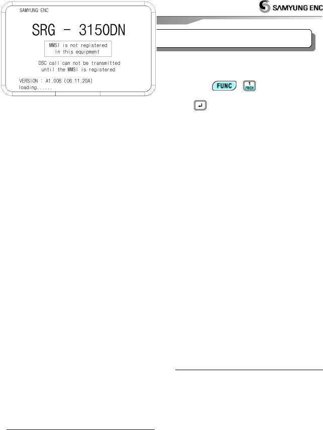
1. Set MMSI ID
|
(Maritime Mobile Service Identity) |
∙ Press |
button and ON, It stop at the below |
initial display, |
|
∙ Then input SELF ID or handle dial/key of the front panel to be operated regularly.
< Initial Screen >
1.1. Self-ID
∙ [DSC] mode  / '9. SYSTEM SET' / '1.Self ID set'
Ex) Input ID 111100000 :
Press any key on the initial screen
Press  to go to [DSC] mode


 twice Press(
 )and then go
out to 'Main Menu'. (Indicated MMSI Number in the right side on the bottom)
2. SSB mode
2.1. Channel Selection
∙ Press  to go to [SSB] modeselect to the channel by dial [CH]
[ Ref. ] Press twice (
 ) and
) and
select to [CH] input channel with [No. button] and then press  .
.
2.2. Frequency Selection |
|
||
1)Press twice( |
|
)and select to [TX] |
|
Input |
frequency by [No. button] |
||
press |
. |
|
|
2) Press twice (
 )and select to [RX]Input frequency by [No. button]
press  .
.
[ Ref. ] Missing frequency range, Cannot be input with alarm sound.
2.3. TX, RX 1) TX
∙Can use it after inputting to the frequency TX/RX that want to communicate.
∙Press  to go to [SSB] mode
input the frequency that want to communicate
Press [Mike switch(PTT)] and communicate. [ Ref. ] Don’t have a ATU Tunning date
valor of the first channel, ATU Tuning run automatically to the emergency TX(2,182 / 2,1875 / 4,2075 / 6,312 / 8,4145 / 12,477 / 16,8045 kHz).
2) Received gain adjustment
∙ Be easy to hear on condition of low noise as down GAIN and up VOLUME.
3. DSC mode
3.1. Channel Selection
∙ Press  to go to [DSC] modeselect to the channel by dial [CH]
[ Ref. ] Press twice (
 ) and
) and
select to the channel [CH] and input the wanted channel by[Number]and then press .
.
3.2. Frequency Selection
∙ Press twice (
 ) and select [TX]Input the wanted frequency by [No. button]
press  .
.
[ Ref. ] Missing frequency range, Cannot be input with alarm sound.
5

3.3. Call
∙ Press  to go to [DSC] modeselect to the channel by dial [CH]


3.4. DSC Message RX Auto Reply
∙When receive DSC message and Auto ACK on, can work automatic answer.
∙When receive DSC but Auto ACK off and then don’t work automatic answer.
(1) How to set
[DSC] mode press / ‘9.SYSTEM SET’ / ‘0.Etc Set’ / ‘4.Auto Ack’ and finished setting.
4. Distress transmit
4.1. Transmit signal(DISTRESS) by Emergency Transmitter KEY
(1)Hold on 3 seconds  [DISTRESS] and then transmit signal.
(2)If you don’t have any reply, flicker the red[DISTS]display as follow on screen and transmit channel from 1 to 6 after 4 minutes(3min.and 30sec ~ 4min.40sec.).
(3)Press  and then stop to transmit.
How to use SN-100 NBDP Terminal
1. Selection of Channel
1.1. Change [CH] on screen
Select wanted channel by [No. button]and press [Enter]
1.2. Press [F6]
Input the wanted channel by [No. button]
Press [Enter]
2. Selection of Frequency 2.1. TX
∙ Press[F7]
input the wanted communicate frequency by
[Number]press[Enter]
2.2. RX
∙ Press[F8]
input the wanted communicate frequency
[Number]
press[Enter]
3. ARQ mode
∙ Hold [F2], Select [ARQ] You can access to one by ARQ MODE.
4. FEC mode
∙ Hold [F2], Select [FEC] You can access to one by FEC MODE.
6

Chapter 1. Overview
∙GMDSS(Global Maritime Distress and Safety System) is an internationally recognized distress and radio communication safety system for ships replacing the previous ship to ship safety system, which relied on a manual Morse code system on 500 kHz and voice radiotelephony on Channel 16 and 2182 kHz. The GMDSS is an automated ship to shore system using satellites and digital selective calling technology.
The GMDSS is mandated for ships internationally by the International Maritime Organization (IMO) Safety of Life at Sea Convention (SOLAS), 1974, as amended in 1988, and carries the force of an international treaty.
∙SRG-3150 and SN-100 are composed of MF/HF transceiver, DSC, DSC W/K Receiver, NBDP, Automatic alarm telephone for suitable automatic digital communication at the distress and safety/normal situation.
SN-100 uses being connected to Transceiver(SRG3150DN), output sub-carrier signal to transmit NBDP data, displays the information on the display which is demodulated RX signal receiving from antennas.
∙SRG-3150DN frequency range :
TX : 1.6MHz~27.5MHz
RX : 500kHz~29.99999MHz
∙ Type of Frequency/Power :
J3E : 150W(HIGH)/100W(MID)/50W(LOW), F1B : 100W(HIGH&MID)/75W(LOW).
1.1. Features
(1) Possible Range
∙ Because MF/HF Transceiver(SRG-3150DN), DSC W/K Receiver, DSC, Distress alarm telephone is built in SRG-3150DN, You are able to use itself without NBDP terminal(SN-100). NBDP function is worked by connecting SN-100 terminal, However it is not available to use NBDP terminal only.
(2) Total Control System
∙SRG-3150DN is set up with the major modules combined as one unit or circuits within a single cabinet. Thus, it is possible to rationalize the total control system by interlinking the respective module controls.
∙And narrow band direct printing is available by connecting NBDP unit(SN-100) to SRG-3150DN simply.
(3) User Friendly
∙ All general operation such as communication, controls and monitoring, are performed by SRG3150DN, NBDP Terminal and printer which is installed in a convenient place.
(4) Configuration
∙SRG-3150DN consists of one unit; therefore a large space is not required for installation and operation.
∙SN-100 Terminal is able to use by connecting with SRG-3150DN cable.
(5) Trustworthy
Adopted new DDS (Direct Digital Synthesize) and improved the quality of sound, trustworthy, stability.
(6) Construction
∙ In order to endure in bad condition of marine environment, hard aluminum body is manufactured.
(7) External Shape
∙ Channel, Frequency, Transmitting and receiving conditions can be seen on large LCD at one sight. And each key is made by soft rubber material. It has stylish shape and makes you feel comfortable when you press the button, Further there is frequency sheet for users. SN-100 NBDP Terminal has large, thin, colorful LCD and convenient keyboard.
7

1.2. Basic Components
∙ This equipment is composed of SRG-3150DN and SN-100(NBDP), each item is made by functional PCB and sorted by standard and option.
<< Standard Components List >>
|
No. |
|
Description |
Model |
|
|
|
|
|
|
|
|
Remark |
|
|
|
|
|
|
1. |
|
MF/HF-DSC |
SRG-3150DN |
|
|
|
|
|
|
|
|
|
|
|
|
|
|
|
|
|
|
|
|
|
|
|
|
|
|
|
|
|
||||
|
(1) |
|
MAIN BOARD |
T - 1110 |
|
1 |
|
|
|
|
|
|
|
|
||||
|
(2) |
|
TX FILTER |
T - 1101 |
|
1 |
|
|
SRG-3150DN |
|
|
|
|
|
||||
|
(3) |
|
W/K RX |
T - 1112 |
|
1 |
|
|
Assembly |
|
|
|
|
|
||||
|
|
|
|
|
|
|
|
|
|
|
|
|
|
|
||||
|
(4) |
|
TX PA |
T - 1113 |
|
1 |
|
|
|
|
|
|
|
|
||||
|
|
|
|
|
|
|
|
|
|
|
|
|
|
|
||||
|
(5) |
|
KEY BOARD |
T - 1114 |
|
1 |
|
|
|
|
|
|
|
|
||||
|
2. |
|
Automatic Antenna Tuner |
SAT-100 |
|
1 |
|
|
(Installation |
|
|
|
|
|
||||
|
|
|
|
|
material included) |
|
|
|
|
|
||||||||
|
|
|
|
|
|
|
|
|
|
|
|
|
|
|
|
|
|
|
|
3. |
|
HAND MIC |
SM-1150 |
|
1 |
|
|
|
|
|
|
|
|
||||
|
4. |
|
Accessory |
SSB-A-C,SRG-2050D-PC |
1set |
|
|
|
|
|
|
|
||||||
|
|
|
|
|
|
|
|
|
|
|
|
|
|
|
||||
|
5. |
|
User, Installation Manual |
SRG-3150DN(Eng) |
|
1 |
|
|
|
|
|
|
|
|
||||
|
|
|
|
|
|
|
|
|
|
|
|
|
|
|
|
|
|
|
|
<< Options Components List >> |
|
|
|
|
|
|
|
|
|
|
|
|
|
|
|
||
|
|
|
|
|
|
|
|
|
|
|
|
|
|
|
|
|
|
|
|
No. |
Description |
Model |
|
|
|
|
|
Q’ty |
|
Remark |
|
|
|
|
|
||
|
1. |
|
EMG Light |
EMG-Light |
1 |
|
|
|
|
|
|
|
|
|||||
|
|
|
|
|
|
|
|
|
|
|
|
|
|
|
|
|
|
|
|
2. |
|
External Speaker |
SS-6000 |
1 |
|
|
|
|
|
|
|
|
|||||
|
|
|
|
|
|
|
|
|
|
|
|
|
|
|
|
|
|
|
|
3. |
|
Power Supply |
SP-1250ADC |
1 |
|
|
|
|
|
|
|
|
|||||
|
|
|
|
|
|
|
|
|
|
|
|
|
|
|
|
|
|
|
|
4. |
|
NBDP Teminail |
SN-100 |
|
|
|
|
|
1set |
|
|
|
|
|
|
||
|
|
|
|
|
|
|
|
|
|
|
|
|
|
|
|
|
|
|
|
(1) |
|
Connection Board |
T - 130 |
|
1 |
|
|
|
|
|
|
|
|
||||
|
|
|
|
|
|
|
|
|
|
|
|
|
|
|
|
|
|
|
|
(2) |
|
NBDP |
T - 132 |
|
1 |
|
|
SN-100 Assembly |
|
|
|
|
|
||||
|
|
|
|
|
|
|
|
|
|
|
||||||||
|
|
|
|
|
|
|
|
|
|
|
|
|
(Installation |
|
|
|
|
|
|
(3) |
|
NBDP PLL |
T - 133 |
|
1 |
|
|
|
|
|
|
|
|||||
|
|
|
|
|
material included) |
|
|
|
|
|||||||||
|
|
|
|
|
|
|
|
|
|
|
|
|
|
|
|
|
||
|
(4) |
|
|
T - 025 |
|
1 |
|
|
|
|
|
|
|
|
||||
|
|
|
|
|
|
|
|
|
|
|
|
|
|
|
|
|
|
|
|
(5) |
|
CPU Board |
G-1151 |
|
1 |
|
|
|
|
|
|
|
|
||||
|
|
|
|
|
|
|
|
|
|
|
|
|
|
|
|
|
|
|
|
5. |
|
KEY Board |
SPR8695 |
|
1 |
|
|
|
|
|
|
|
|
||||
|
|
|
|
|
|
|
|
|
|
|
|
|
|
|
|
|
||
|
6. |
|
MF/HF Distress Box |
SD-250 |
|
1 |
|
|
(SCN-16-5P included) |
|
|
|
|
|||||
|
|
|
|
|
|
|
|
|
|
|
|
|
|
|
|
|
|
|
|
|
|
|
|
|
|
|
|
|
|
|
|
(Installation |
|
|
|
|
|
|
7. |
|
Printer |
DPU-414 |
|
1 |
|
|
material included) |
|
|
|
||||||
|
|
|
|
|
|
|
|
|
|
|
|
|
(or OKI Printer) |
|
|
|
||
|
8 |
|
WHIP ANT (TX) |
SAN-308 |
|
1 |
|
|
(8m) |
|
|
|||||||
|
|
|
|
|
|
|
|
|
|
|
|
|
|
|
|
|||
|
9. |
|
WHIP ANT (RX) |
SAN-30R |
|
|
|
(6m) |
|
|||||||||
|
|
|
|
|
|
|
|
|
|
|
|
|
|
|
|
|
|
|
8

Chapter 2. Specifications
2.1. General specification
∙ This radio equipment SRG-3150DN has been tested by the recommendation standard of IMO.
(1) Power Supply (SP-1250ADC)
AC 100-120/200-240V, 50/60Hz, 6% single-phase, DC24V Power Supply : 1200VA (Max)
(2)Consumption Current: DC24V ±15% Receiving: 2.5A, at transmitting: 15A (Max)
(3)Frequency Selection
a)ITU CHANNEL (Maritime Mobile) 271
b)299 USER CHANNEL (Editable at the screen) or set frequency directly by keyboard.
c)DSC CHANNEL 2187.5, 4207.5, 6312, 8414.5, 12577, 16804.5 kHz (FIB) is scan receiving all the time.
d)DSC Channel 13EA (Editable).
(4)Frequency Switching Time:
Between CHANNEL - within 5sec, Between BAND - within 15sec
(Including ANTENNA MATCHING TIME)
(5) Ambient Condition Temperature : -15 ~ +55
Humidity: 95%, +55
Oscillation :Full amplitude 3.2mm at 5 ~ 12.5Hz Full amplitude 0.8mm at 12.5 ~ 25Hz Full amplitude 0.2mm at 25 ~ 50Hz
(6) Dimensions (mm)
SRG-3150DN : 324(W) X 170(H) X 347(D)
SN-100 |
: 300(W) X 255(H) X 125(D) |
|
(7) Weight |
|
|
SRG-3150DN about |
8.1Kg |
|
SN-100 |
about |
5 Kg |
SAT-100 |
about |
3.4Kg |
2.2. MF/HF Transmitter
(1)Type of Emission : J3E (USB), F1B (FSK)
(2)Type of Communication
:SIMPLEX & SEMI DUPLEX
(3)Frequency Range :TX 1.6MHz - 27.5MHz, 10Hz STEP
(4)Continuous Operating:
Operating for over 8hrs with transmitting for 1minute, stand by for 4minutes.
(5) Output Power:
50 ohm loaded (MF/HF transmitter output)
a)AC : 1.6MHz-27.5MHz 150WPEP
b)DC : 1.6MHz-27.5MHz 75WPEP
c)Power Reduction: 3steps
J3E : 50 / 100 / 150W
F1B : 75 / 100 / 100W
(6) Frequency Deflection: Below 10Hz (within 0.3ppm)
(7) Number of Channels:
SSB x 299, ITU x 271, DSC x 19
(8) Modulation type:
Low power stage balanced modulation
(9) Occupied Bandwidth:
J3E …… within 3kHz , J2B … within 0.5kHz
(10)Carrier Attenuation : 40dB or more (J3E)
(11)Spurious Attenuation
J3E: 1.5 - 4.5 kHz |
31dB or more |
|
|
4.5 - 7.5 kHz |
38dB or more |
|
7.5 kHz or more |
43dB or more |
F1B: 138Hz |
15dB or more |
|
|
76Hz |
31dB or more |
|
500Hz |
43dB or more |
(12) |
Overall Frequency: |
|
Deflection 6db max. At 350 - 2,700Hz |
||
(13) |
Overall Distortion and Noise : 20dB or more |
|
(14) |
Out Impedance |
: 50ohm |
(15) |
Input Low Frequency: |
|
+10dB/-35dB, IMPEDANCE 600 ohm
2.3. MF/HF Receiver
(1) Type of Emission:
J3E (USB), H3E (only RX), F1B (FSK)
(2) Reception method:
Up conversion double super heterodyne type using phase-locked digital frequency synthesizer. First intermediate frequency: 49.455MHz
Second intermediate frequency: 455 kHz
(3) Frequency Range:
500 kHz - 29.99999MHz 10Hz STEP
(4) Voice Output : Max 5.6W or more
(5) Receiving Sensitivity:
SSB is less 3 at the 500KHz~29.9999MHz
i.e., SSB (S+N+D)/ (N+D) = 20dB, BAND width 3 kHz, Output 100mW
In case of DSC, NBDP Symbol error rate at a receiver input voltage of 1 is less than 1 x 10⁻² i.e., Receiving Mode: FSK, BAND width: 0.3 kHz
(6)1 signal selectivity
a)3 kHz FILTER (for SSB) in detailed features The pass band below 6dB: 2.4 kHz ~ 2.8 kHz The pass band at an attenuation of 26dB is less
than ±1.7kHz
The pass band at an attenuation of 46dB is less than ±1.9kHz
The pass band at an attenuation of 66dB is less than ±2.1kHz
b)0.3 kHz FILTER (for DSC, NBDP)
Below 6dB of the pass band is 270Hz ~ 300Hz Attenuation at ±380Hz is 30dB or more Attenuation at ±550Hz is 60dB or more
9
(7)Clearness: ±120Hz
(8)Overall Distortion & Noise :
With an input voltage of 30uv, the ratio between an audio frequency output of 1000Hz and its unwanted component is more than 20db.
(9) AGC characteristics :
Change in audio frequency output for antenna between 3 and 100mV is 10db or less.
(10)Frequency Stability: within ±10Hz
(11)Image frequency interference ratio : Above 70dB
(12)Intermediate frequency interference ratio: Above 80dB
(13)SPURIOUS RESPONSE : Above 70dB
In case of DSC, NBDP
When a wanted signal of 10 and a 31.6
unwanted signal(excluding the range within 750Hz of the wanted signal) whose range of IF it's three times that of the wanted signal, the symbol error rate is less than 1 x 10⁻².
(14) Selectivity Suppression : With a wanted signal of 10 and an unwanted signal that is effect
than 3kHz from the wanted signal, an unwanted signal input voltage of 10m suppresses the wanted scanning output to 3db.
In case of DSC, NBDP With a wanted signal of 10and 1 unwanted signal 500hz from the
wanted signal, the character error rate is less than 1 x 10⁻².
(15) Spurious Emission :
The power of emission from air antenna terminal is less than 4000 .
(16) Nominal input load : 50 ohm unbalanced
2.4. DSC (Digital Selective Calling)
W/K Receiver
(1) |
Type of Emission : F1B |
|
|
|
|
||
(2) |
Frequency |
: 2 187.5, 4 207.5, 6 312, |
|
||||
|
|
8 |
414.5, |
12 |
577, |
16 |
804.5 |
|
|
kHz |
|
|
|
|
|
(3) |
Frequency Stability |
: within ±10Hz |
|
|
|||
(4) |
SCANNING Reception : |
|
|
|
|
||
Scanning reception of above frequencies is continued up to 2sec for each frequency and stop only when detects a 100 baud dot pattern.
(5) Receiving Sensitivity :
Character error rate is 1 x 10⁻² or less at receiving
input voltage 1 . |
|
|
(6) |
1 signal selectivity |
|
6dB bandwidth |
: 270 ~ 300Hz |
|
30dB bandwidth |
: within ± 380Hz |
|
60dB bandwidth |
: within ± 550Hz |
|
(7) |
Nominal input load |
: 50 ohm unbalanced |
(8) |
Display DSC received word : |
|
Maximum 256EA (Figure and word)
10
(9) SPURIOUS RESPONSE:
With a wanted signal of 10 and 31.6 zero
modulated interference signal which excludes the range within 750hz of the wanted signal, the character error rate is less than 1 x 10⁻².
(10) Spurious emission:
The power of emission from air antenna terminal is less than 4000 .
2.5. MF/HF Control
(1)Control Items : MF/HF Transceiver,
DSC, WATCH-KEEPING Receiver, Frequency Program.
(2)DISTRESS :
Transmitting 2187.5, 4207.5, 6312, 8414.5, 12577,
16804.5 kHz
(3) |
Miscellany |
: |
DISPLAY, Remote Interface, NBDP terminal, |
||
ATU BOX, ALARM BOX, HAND MIC, |
||
Printer, DIMMER |
||
(4) |
MAIN PROCESSOR : HD64F2506 |
|
(5) |
EEPROM |
: 24LC512 |
(6) |
Display |
: LCD BACK-LIGHT DISPLAY |
(7) |
INTERFACE |
|
RS-232 INTERFACE |
: 1 |
CHANNEL (NBDP) |
RS-422/232 INTERFACE : 1 |
CHANNEL (GPS) |
|
PRINTER INTERFACE |
: 1 |
CHANNEL |
(CENTRONICS INTERFACE) |
|
|
2.6. Digital Selective Calling (DSC)
(1) |
PROTOCOL |
: CCIR recommendation 493-3 & 541-2 |
(2) |
EMISSION |
: F1B/J2B 100BAUD |
(3) |
Modulator |
: Output frequency 1700Hz ±85Hz |
|
|
Output max LEVEL +10dBm |
|
|
(600 ohm Unbalance/Balance) |
(4) |
Demodulator : Input frequency 1700Hz ±85Hz |
|
|
|
Input LEVEL -20dBm ~ +5dBm |
|
|
(600 ohm Unbalance/Balance) |
(5) |
Processor: |
|
CCIR recommendation 493-3ERROR mark (10 steps) Correct CLOCK transmitting
CLOCK frequency 14,000 KHz CLOCK stability within 5 x 10⁻⁶.
(6) DSC Memory Function |
|
|
∙ Distress Receipt |
: |
50EA |
∙ Ordinary |
: |
50EA |
∙ Transmit message |
: 100EA |
|

2.7. Narrow band direct Printing (NBDP)
(1) Protocol :
CCIR recommendation 625.476-4.490491.492-3
&CCIR F130
(2)Calling mode :
Individual and group calling with 5 digits and 9 digits select call number.
(3) Operating mode :
ARQ (Auto Repetition Request)
CFEC (Collective Forward ERROR correction) SFEC (Selective Forward ERROR Correction)
(4) Status Display :
POWER ON, STAND-BY, CALLED, CALLING, FREE. SIGNAL, ARQ, CFEC, SFEC, SEND, RECEIVER, PHASING, REPHASING, REPEAT, ERR
(5) Code :
7-bit CORD 4B/3Y constant ratio mark signal (B:1785Hz, Y:1615Hz)
(6)Memory : 16M
(7)SYSTEM PARAMETER:
OPERATOR DATA |
is saved at FLASH DISK |
PROGRAMING and back-up. |
|
(8) Center frequency |
: 1700Hz |
(9)Frequency SHIFT width: ±85Hz
(10)Modulation Speed : 100BAUD (ARQ, FEC MODE)
(11)Modulation: phase continuity AFSK
(12)Frequency Deflection: within 0.5Hz
(13)Modulation Input :
0dBm, 600ohm Unbalance/Balance (14) Modulation Output:
0dBm, 600ohm Unbalance/Balance
2.8. Printer (DPU-414)
(1) Specifications |
|
∙ Typing |
: Thermal serial dot matrix |
∙ Total Dots |
: 9 x 320 dot / line |
∙ Composition of Dots: 9 x 7 dots wide |
|
∙ Internal Dots |
: 1 dot |
∙ Typing Quantity |
: |
40letters (Standard) 80letters (Shortened)
∙Typing Direction : Single / Both Logical seek
(2)Bit-image graphics mode
∙ Total Dots |
: 8 x 320 dot / line |
∙ Typing Direction : Single Logical seek |
|
∙ Typing width |
: 89.6mm |
∙ Typing speed |
: Max 52.5cps (Standard |
Max 80cps (Shortened)
(3)Ambient
∙Temperature: 0 ~ 40
∙Humidity: 30 ~ 80 RH(no condensation)
(4)Print Paper
∙ Model No |
: TP411 - 28CL(TP-411L) |
∙ Width |
: 112mm |
∙ Diameter |
: 48mm |
∙ Length |
: about 28m |
(5) Etc |
|
∙ Power Supply |
: DC 6.5 ~ 13.6V |
∙ Dimensions |
:160mmx 170mmx 66.5mm |
∙ Weight |
: about 580g |
∙ Durability |
: about 500,000 lines |
("8" 40letters continuously) (Color thickness 100 )
2.9. Printer (OKI)
(1) Features |
|
∙ Printer Head |
: 9 pins |
∙ Speed (CPS) |
: 300CPS (Max speed) |
|
240CPS (High speed) |
|
50CPS (High quality) |
∙ Carriage width |
: 80letters (10CPI) |
∙Graphic Resolution : 240X216DPI (Max)
∙Paper Space : From top 15mm (CUT SHEET) From top 17mm (ROLL)
∙Interval between letters : 10, 12, 17CPI
∙Type of Font: Dark, Stress, Thick, Lean
∙ Remember |
: 1 Line |
(2) Paper |
|
∙ Dimensions |
: 241 ~ 254mm |
∙ Weight |
: 35 ~ 52 g/m2 |
(3) Interface and Standardization |
|
∙ Standardization |
: micro line espon fx ibm |
|
pro printer |
∙ Interface |
: centronics parallel |
|
serial rs232c, rs422 |
(4) Reliability |
|
∙ Head Life |
: 2 billion letters |
∙ Ribbon Life |
: 3 million letters |
∙ MTBF |
: 6000hrs |
(5) Miscellany |
|
∙ Power |
: DC +24V |
∙ Dimensions (HXWXD): 80mmX360mmX275mm |
|
∙ Weight |
: 4.5Kg |
∙ NOTE |
: DC available (10~30V DC) |
11

Chapter 3. Power Supply
3.1. Power On
(1)AC power plug put in plug receptacle, connect the battery with rear socket.
(2)Check the indication of light on: AC IN, DC IN, and DC OUT of front panel.
(3)Connect cables of SRG-3150DN.
(4)Switch AC and DC power on.
(5)Push the  button.
3.2. Operation by AC power
∙ When it comes to supply AC power to the main unit, it works with AC power automatically. W/K LED displays the condition that 6 scanning frequency is working on DSC WKR of the transceiver. (Refer to "Operation of Distress Acknowledge Signal" for operation instructions, If DSC distress or alarm call rings.)
3.3. Operation by DC (BATTERY) power
∙ When AC power is disconnected, the SRG-3150DN switches to DC operation and [DC] LED on MF/HF control panel will light up automatically.
When it is transmitted to DSC, AC signal will be changed to DC on upside of transceiver LCD display. Moreover, changing to DC mode will be displayed on downside of that.
And receiving output is converted to LOW.
3.4. BATTERY Charging
∙ When connected to AC power, except of switch on of transmitter power supply AMP power, the battery is automatically charged, a low current is supplied to maintain the rated battery voltage.
The charge mode indicator between automatic and normal is by the charge switch on the system cabinet.
(1)AUTO MODE: When the battery is out, charged automatically, Full time charged is set general mode.
(2)NORMAL MODE: It is charged battery, regardless battery is status. To use battery longer, it is required to maintain properly for battery.
Maintaining battery according to the instruction manual.
(3)OFF MODE: Set the middle of switch between AUTO & NORMAL.
12

Chapter 4. Front Panel
4.1. About Button, Knob, Lamp
< SRG-3150DN Main Unit >
. KEY Panel
. Front Panel(LCD) - Mode / Frequency / Channel
/ Other function.
. Internal Speaker
. MIC connection jack - Connect MIC provided.
. Articulation - Adjusting received signal clearly.
. Gain - Adjusting Gain of Receiver.
. Volume - Adjusting volume of speaker.
. Channel - Adjusting channel and frequency up/down.
(1) |
: Power ON / OFF in main unit. |
(2) |
: Hold pressing 3sec, Transmitting |
Distress signal.
(3) : Transmitting frequency/channel & message edited by DSC mode or Stop alarm sound, Stop distress and call display also.
(4) : Auto acknowledge for the received messages ON/OFF in DSC mode.
(5): Selecting main menu.
(6): Hold this key and extend functions with random keys.
|
|
: Selecting "CH" "TX" "RX" in |
|
|
Order. (Be available to select |
|
|
Channel and TX/RX Frequency) |
|
|
: Select ATT in order. |
|
|
(Display LCD left-bottom) |
(The part of received diminution can select 3 levels)

 : ON/OFF internal test tone Signal at 1.4 KHz.

 : ON/OFF Scan function. (Display LCD on top)
(Scan function of channel or frequency can be started and finished)

 : ON/OFF Speaker. (Display LCD on top)

 : Select printer function.
(Can be printed to channel and message that received frequency)

 : ON/OFF N.B.
(Display LCD left-bottom) [Ref.] when it is receiving H3E, Noise
Blanker removes noise out of it.
(Noise Blanker: It works to block high level of impulse of short duration as a device to cut off one stage from middle frequency of receiver.)
13

|
|
: ON/OFF AGC. |
|
|
(Display LCD left-bottom) |
Adjust automatically gain that bundle of amplification of receiver.
(Auto Gain Control: It means that system maintain to regardless of changing of strength that input signal by the book of receiver’s power. As is higher signaling that incoming to system, diminution degree of gain is increasing, in conclusion low signal much more amplifier than high signal).
|
|
: ON/OFF SQL. |
|
|
(Display LCD left-bottom) |
Delete to noise that occurred on standby receiving according to signal level.
(*Squelch: mute the equipment and delete to harassing background noise and unwanted signal automatic control to the function of receiver or amplifier exception of incoming signal exceed to a set point)

 : By check mode, RX set displays RX signal(RxG), Voltage(24V)(VOLT), TX set displays PA currency(Ic), Antenna currency(ANT), standing wave ratio(SWR).

 : Adjust dimmer 5steps in front panel.
|
|
: Switch AM receiving mode. |
: Operating matching channel
before input frequency.
 [▲]or[▼] : Change of TX Frequency take turns HIGH / LOW / MID.
(7): this button is for selecting to item of
selection on menu mode and for cursor moving on the display.
(8)~ : be useful to input the number.
(9): Adjust LCD back light (internal) by 4steps. (Holding [FUNC] and press [DIM], Adjust
by 5steps.)
(10)  : Switch SSB & DSC mode.
(Holing [FUNC] and press [MODE], Switch AM mode.)
[Ref.] SSB (J3E): use to voice communication DSC (F1B): use to digital selective
calling communication
(11) : Matching with user's antenna then push this button. (Press [FUNC] and hold with [ATU] for 2sec, Matching all channel.)
(12): Cancel set or return precious menu.
(13): Execute selecting, input, and extend...etc at the menu.
14
(14) LED Display
[DISTS]: When receive a Distress signal by W/K receiver or transmit a Distress alarm signal, be flickered LED indicator.
[OTHER]: when receive DSC without DISTRESS signal, be flickered Green LED Indicator.
[TX] : LED on, transmitting
[W/K]: LED display …… LED on W/K receiver is operating. (Always Working)
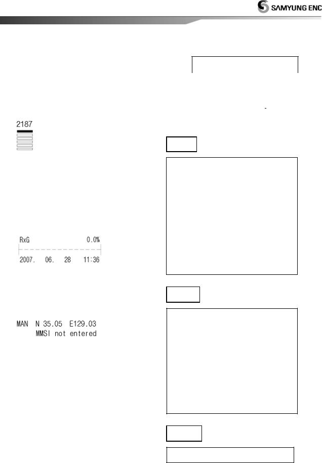
4.2. LCD display
The following information is displayed in general.
(1)Communication Mode (SSB, DSC, AM (only RX)), Speaker, Acknowledge, Scan, TX power, Time (UTC GPS being connected)
(2)W/K receiving channel, TX/RX frequency & channel.
(3)Attenuator (ATT), Noise Blanker (N.B), AGC, Squelch.
(4)RX signal level, Voltage/Currency (I-c) / (ANT- c)/ Standing-wave ratio (Select [F] + [0]), Date, time (Display UTC, if GPS receiver connected)
(5)Location mark
“MAN”: Manual Input
“GPS”: GPS location (GPS connected) MMSI (Maritime Mobile Service Identity) ID
(6)Display according to the key input.
(7)Display Description
A)  : Display communication mode in use.
b):
 , ON/OFF Speaker
ON - Display
OFFDisplay
c) ACK : Display if it selected an automatic acknowledge in DSC mode.
d) SCN : Press |
|
to start |
"SCAN" and press |
|
, and then |
SCAN is finished. |
|
|
e) HIGH : Display transmitting power.
HIGH : SRG-3150DN (J3E:150W, FIB:
100W) |
|
|
MID : |
SRG-3150DN |
(J3E:100W, |
F1B:100W) |
|
|
LOW : SRG-3150DN (J3E:50W, F1B:75W)
f)F: Display  is in use or not.
g)AC : Indicate currency situation to POWER SUPPLIER (SP-1250ADC).
AC : AC Power Supply.
DC : battery power supply.
H): Display scanning W/K frequencies
(6 channels).
i)TX : Transmitting Frequency
j)RX : Receiving Frequency
k)ATT3 : Level of attenuation.
ATT1: 10dB, ATT2: 20dB, ATT3: 30dB
l)NB : Display Noise Blanker set.
m)AGC : Display Auto Gain Control.
n)SQL : Display Squelch set.
o)CH : Display channel.
p) |
: indicate a |
received gain and use to button and can select to
indictable to 
 SWR(standing wave ratio) / VOLT(PS current) / IC(TX current) / ANT(Antenna currency), indicate to date and time and automatic indicate to UTC when connected GPS, GPS receiver
q) |
: Indicate GPS |
received date (latitude, longitude) when input hand
– operated coordinate, receive directly date from GPS receiver and indicate screen to “GPS”, indicate tuning situation in changing channel with MMSI ID.
4.3. LCD display flow
MAIN DISPLAY
|
|
|
|
|
|
|
|
|
|
|
|
|
|
|
|
|
|
|
|
|
|
|
|
|
|
|
|
|
|
|
S S B |
|
|
|
D S C |
|
|
|
AM (H3E) |
|
||||
|
|
|
|
|
|
|
|
|
|
|
|
|
|
|
SSB
MAIN MENU 1. Scan Type Set
2.Scan Channel Set
3.Scan Frequency Set
4.SQL Set
5.LCD Contrast Set
6.TX POWER Set
7.Manual Tuning
8.ATU - VERSION
9.Remote Set
0. SYSTEM Set
DSC
MAIN MENU 1. Distress msg edit
2.Individual msg edit
3.Group msg edit
4.Geography msg edit
5.Auto/Semi-AT msg edit
6.Dist. ack/rly msg edit
7.Ordinary ack msg edit
8.Display & Print msg
9.System Set
AM
*** Only Receive Function
15

Chapter 5. SSB (TEL) mode
5.1. SSB Mode
Press  button on front panel, and then go to SSB mode.
5.2. SSB Menu
On SSB Mode when press display to Menu screen as follow.  .
.
(1) Scan Type Set
a) Decision scanning channel or frequency.
1. Scan Type is selected.
Select, switching [CH]/ [Freq] in rotation
Return to Main Display.
B) ,
, scan to select SACN Type.
[Ref.] Scan type is [CH], scan channel. Scan type is [Freq], scan frequency.
(2) Scan Channel Set
a)Fix setting value in case of scanning channel.
2.Scan Ch. Set is selected.
The below box shows.
|
|
|
Start |
: |
1 |
End |
: 299 |
|
Speed |
: |
0 |
|
|
|
16
[▲][▼] Move, and select to wanted function,
Selected. |
|
[Number button] |
Input the value. |
Set up. |
|
Press to back to main screen. |
|
[Ref.] [Start] |
: Set Start channel. |
[End] : Set Last channel. [Speed] : Set speed of scan channel
(0~9, 0: Fastest, 9: Slowest)
(3) Scan Frequency Set
a)Set value in case of scanning Frequency.
3.Scan Freq. Set is selected.
The below box shows.
Start |
|
: |
500.00 |
kHz |
End |
: |
29,999,99kHz |
||
Speed |
: |
0 |
|
|
Step |
: |
0.1 |
kHz |
|
[▲][▼] Move, and select to wanted function,
Selected. |
|
[Number Button] |
Input the value. |
Set up. |
|
Press to back to main screen. |
|
[Ref.] [Start] |
: Set Start Frequency. |
[End] : Set Last Frequency. [Speed]: Set speed of scan Frequency. [Step] : Set step of scan Frequency.
(100HZ/step)
“10.0”at 10kHz step.
(4) SQL Set
a) On standby, if set setting value of SSB particular sound clearance highly, cannot receive slight signal.
4. SQL Set is selected.
The below box shows.
|
|
SQL |
Sense |
10 |
Set range : 1 ~ 20 |
|
|
SQL |
Delay |
5 |
Set range : 1 ~ 20 |
[▲][▼] Move, and select to wanted function, |
|||||
|
|
Selected. |
|
|
|
[Number button] |
Input the value. |
||||
|
|
Set up. |
|
|
|
Press to back to main screen.
[Ref.] [SQL Sense]: Set sensibility of SQL. [SQL Delay]: Set delay time of SQL circuit.
(5) LCD Contrast Set
5. LCD Contrast is selected.
Press to change the LCD brightness From [1] ~ [5] step.
(Higher value and more thicker)
(6) Tx Power Set a) Adjust TX power.
6.Tx Power is selected.
Select HIGH / MID / LOW b) If Tx Power
HIGH, Display "HIGH", SRG-3150DN(J3E:150W, FIB:100W)
MID, display "MID", SRG-3150DN(J3E:100W, F1B:100W)
LOW, display "LOW". SRG-3150DN(J3E:50W, F1B:75W)
(7) Manual Tuning
a) ATU tuning by manual.
7.Manual Tuning is selected.
The below box shows.
TX Power : Tune
▼
 0.0 uH
  OFF
OFF 

 OFF
OFF 

0 pF |
0 pF |
OFF |
[ ][ ] Select the point which it is to be adjusted by[ ][ ]
[▲][▼] Adjust it’s value by [▲][▼]
Selected.
[Ref.] press , the value adjusted is input
and return main menu.
On manual tuning, TX power has not changed while switching frequency.
(8)ATU – Version (ATU Program Version)
8.ATU---Version is selected.
Selected.
[Ref.] if ATU DATA cable has any trouble, Display "Error.”
(9) Remote Set
a) Set remote operating.
9. Remote OFF is selected.
Press, can be changed 9.Remote ON,
Display "REM" on the main screen. b) Press  and then change to remote off.
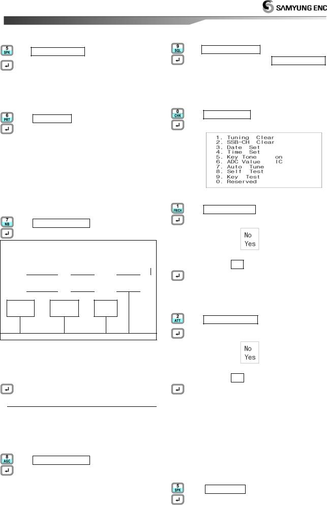
(10) System Set
a)Select system’s value.
0.System Set is selected. The below box shows.
[1.Tuning Clear]: Clear all the memory tuned.
1. Tuning Clear is selected.
The below box shows.
[▼] Move to Yes
Reboot system.
[2.SSB-CH Clear]: Delete channel data and set channel.
2. SSB-CH Clear is selected.
The below box shows.
[▼] Move to Yes
Reboot system.
[3.Data-Set]: Set data in system.
In external GPS Data input, UTC (Universal Time Coordinated) is displayed.
[4.Time-Set]: Set time in system.
In external GPS Data input, UTC (Universal Time Coordinated) is displayed.
[5.Key Tone]
5.Key Tone is selected. Press, can be changed On/Off.
17
 Loading...