

Samsung Z540 Service Manual EVAPL
3. Exploded View and Parts List
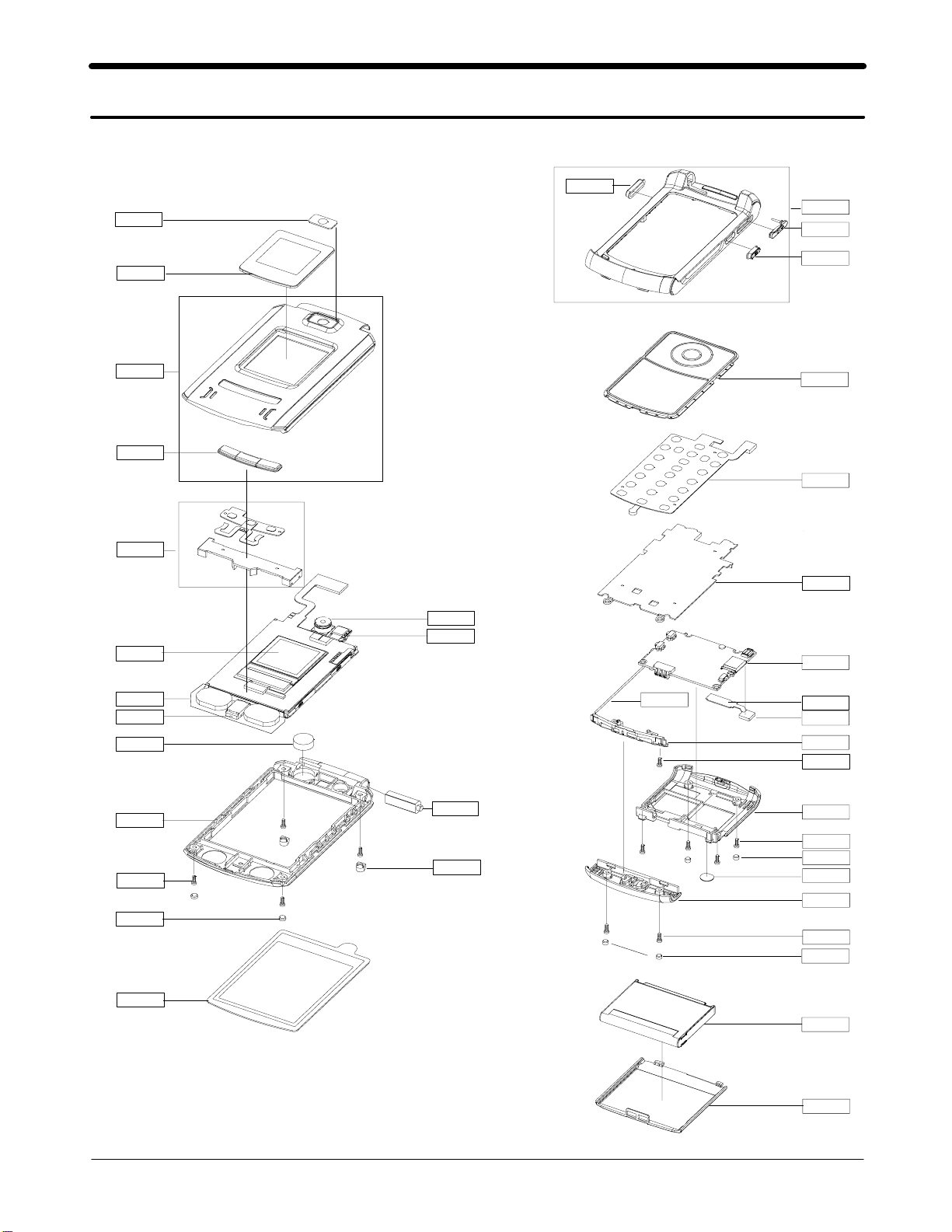
3-1. Exploded View
QCW01
QWD01
QVO01
QFR01
QIF01
QCK01
QFU01
QKP02
QLB02
QLC01
QME06
QAR01
QMO01
QFL01
QCR12
QSC01
QCA01
QCA02
QHI01
QSC14
QCB01
QKP01
QME02
QSH01
QMP01
QME04
QBM01
QAN02
QCR12
QRE01
QCR12
QSC13
QRF01
QAN06
QCR04
QSC13
QMW04
QBA01
QBA00
3-1
SAMSUNG Proprietary-Contents may change without notice
This Document can not be used without Samsung's authorization
Exploded view and Part List
3-2. Parts List
Location NO. Description SEC CODE
QAN02
QAN06
QAR01
QBA00
QBA01
QCA01
QCA02
QCB01
QCR04
QCR12
QCW01
QKP01
QLB02
QLC01
QME02
QME06
QMO01
QMP01
QMW04
QRE01
QRF01
QWD01
QSC01
QSC13
QSC14
QSH01
QBM01
QFU01
QFL01
QFR01
QME04 UNIT-BTFPCB GH59-02750A
QKP02 MEC-KEY FOLD(MP3) GH75-09034A
QHI01 MEC-HINGE GH75-04334D
QCK01 PMO-CAMERA KEY GH72-26932A
QIF01 PMO-COVER IF GH72-26917A
QVO01 PMO-VOLUME KEY GH72-26931A
ELA ETC-Z540 BLUETOOTH MODUL GH96-02136A
INTENNA-SGHZ540 GH42-00723A
MEC-CASE INTENNA FOLDER GH75-08620A
AUDIO-RECEIVER 3009-001173
PMO-CASE BATTERY FOLDER GH72-26922A
BATTERY-880MAH,BLK,MAIN GH43-02253A
UNIT-MEGA CAMERA GH59-02709A
UNIT-VGA CAMERA GH59-02710A
CBF COAXIAL CABLE GH39-00403A
SCREW-MACHINE 6001-001479
SCREW-MACHINE 6001-001530
PCT-COVER CAMERA WINDOW GH72-28463A
MEC-KEYPAD(OMN/BLK) GH75-09169A
NDC-BRACKET MP3 KEY GH71-05913A
LCD-SGHZ540 MODULE GH07-00822A
UNIT-KEY PAD GH59-02667A
UNIT-SPK FPCB GH59-02671A
MOTOR DC-SGHZ540 GH31-00218A
PBA MAIN-SGHZ540 GH92-02496A
MEC-COVER MAIN WIN(VODA) GH75-09036A
MEC-REAR COVER GH75-08621A
MPR-TAPE RF HOLE GH74-20208A
PCT-COVER SUB WINDOW GH72-28461A
RMO-CAP FOLDER TOP GH73-05894A
RMO-COVER REAR GH73-05901A
RMO-COVER FOLDER BOT GH73-05895A
MEC-BRACKET SHIELD GH75-09118A
MEC-FOLDER UPPER GH75-08617A
MEC-FOLDER LOWER GH75-08618A
MEC-CASE FRONT FOLDER GH75-08619A
3-2
SAMSUNG Proprietary-Contents may change without notice
This Document can not be used without Samsung's authorization

Exploded view and Part List
Description SEC CODE
BAG PE 6902-000378
BAG PE 6902-000634
CBF INTERFACE-DATA LINK CABLE GH39-00444A
ADAPTOR-SGHD800 TA(EU) GH44-01060A
S/W CD-PC STUDIO GH46-00198A
UNIT-EARPHONE GH59-02499A
SPRING ETC-BATT LOCKER GH61-00120A
LABEL(P)-IMEI GH68-01335D
LABEL(P)-WATER SOAK GH68-02026A
LABEL(R)-MAIN(EU) GH68-08783A
MANUAL USERS-VODA ITALIAN GH68-08843A
BOX(P)-UNIT(EU NEW) GH69-02908A
BOX(P)-SLIP CASE(EU) GH69-03488A
CUSHION-CASE(1-2) GH69-03556A
MPR-BOHO VINYL LCD CONN GH74-15350A
MPR-TAPE MAIN WINDOW GH74-20193A
MPR-TAPE LCD MASKING 1 GH74-20203A
MPR-TAPE LCD MASKING 2 GH74-20204A
MPR-TAPE INTENNA CABLE GH74-20205A
MPR-TAPE FPCB BLUE GH74-20434A
CONE GH74-20459A
MPR-VINYL BOHO LCD MAIN GH74-20460A
MPR-VINYL BOHO F/L(S) GH74-20460B
MPR-VINYL BOHO LCD SUB GH74-20461B
MPR-VINYL BOHO MP3 KEY GH74-20790A
MPR-VINYL BOHO MP3 KEY GH74-20790A
MPR-TAPE BLUE SHIELD GH74-20844A
MPR-CUSHION MP3 KEY GH74-21083A
MPR-CUSHION MOTOR GH74-21084A
MPR-TAPE MIC MASK GH74-21217A
MPR-VINYL BOHO SIDE KEY GH74-21328A
MPR-SPONGE UPPER GH74-21434A
MEC-HANGER(BLK) GH75-08867E
3-3
SAMSUNG Proprietary-Contents may change without notice
This Document can not be used without Samsung's authorization
Exploded view and Part List
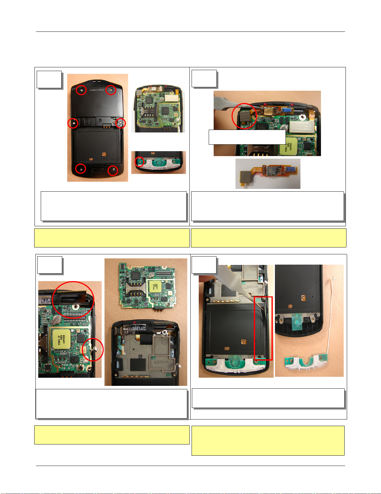
3-3. Disassembling Manual
1
1) After remove screw cap with tweezers, Unscrew.
2) Remove REAR and INTENNA COVER.
3) Unscrew from the INTENNA.
1) When you use tweezers, Be careful a damage of
component.
2
Remove B/T MODULE from th
e BT connector.
1) Remove B/T MODULE from the BT connector.
2) Remove B/T MODULE from attached to Front with
tweezers.
1) When you remove the B/T MODULE, Be careful crack
and damage of the BT MODULE.
3
1) Remove LCD Connector and INTENNA Connector from
the PBA.
2) Remove PBA from the FRONT ASS'Y.
1) Pay attention to tear of the FPCB.
2) Pay attention to damage of the wire.
4
1) Remove INTENNA WIRE Tape with tweezers.
2) Remove INTENNA and INTENNA WIRE.
1) When you remove the tape, pay attention to damage
of the INTENNA WIRE.
2) Be careful handling INTENNA. (Don't touch intenna pattern.)
3-4
SAMSUNG Proprietary-Contents may change without notice
This Document can not be used without Samsung's authorization
Exploded view and Part List
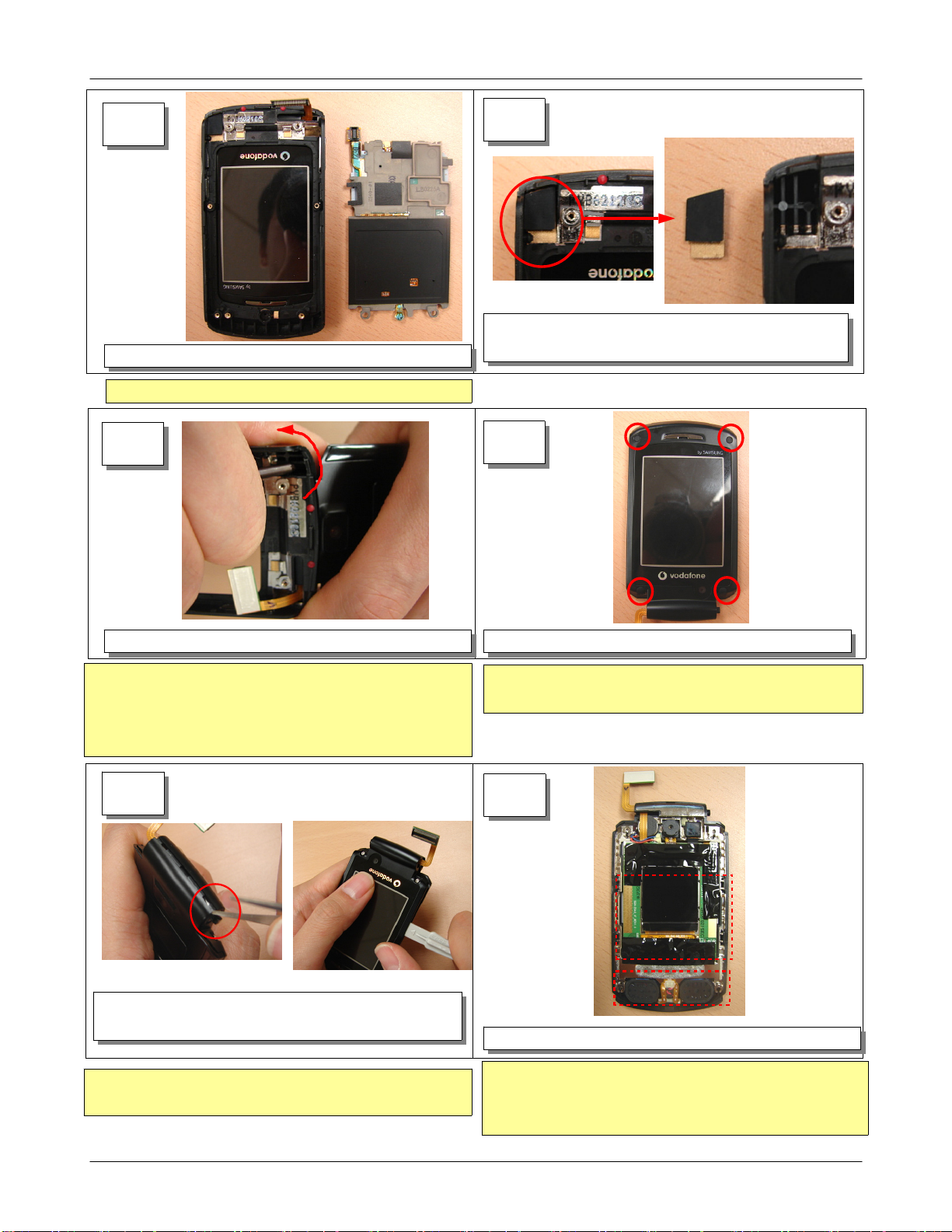
5
1) Remove SHIELD CAN and KEY PAD from the FOLDER ASS"Y.
Disjoint KEYPAD and SHIELD CAN together.
1)
7
6
1) Remove conduction Tape and Rubber from the FOLDER
ASS'Y with tweezers.
8
1) Using a disassemble stick, Disjoint the Folder like the Photo.
1) When you disjoint the Folder, pay attention to damage
of the LCD F-PCB.
2) When you use a disassemble stick, Be careful a damage
of component.
9
1) Disjoint the Folder of the Bottom with tweezers.
2) Using a disassemble stick, disjoint the Folder of the Side.
1) When disjointing UPPER, pay attention to damage of
the wire.
1) After remove screw cap with tweezers, Unscrew.
1) When you use a screwdriver, Be careful a damage
of component.
10
1) Romove the LCD PROTECTION TAPE with tweezers
1) Pay attention to a finger mark and dust of the LCD.
2) When you use tweezers, Be careful a damage of
component.
3-5
SAMSUNG Proprietary-Contents may change without notice
This Document can not be used without Samsung's authorization
 Loading...