

Page 1

Wall Mount Setup Guide
Guide de montage mural
BN68-01537H-00
BN68-01537H-00.indb 1 2012-10-29 오후 5:22:58
Page 2
Contents
Safety Precautions
Safety Precautions 01
Introduction
Unpacking 02
Attaching the bracket ⓐ to the monitor 03
Mounting the bracket ⓑ onto a wall 04
Different bracket types by product models
and specications 05
Arranging the monitors 07
Fine tuning 08
Detaching the monitors 10
Product specications
Product specications 12
Product drawings
Product drawings 13
BN68-01537H-00.indb 1 2012-10-29 오후 5:22:58
Page 3

Safety Precautions
English
The information contained herein is for your safety and
to prevent any loss of property.
This mandatory sign is used to emphasize
the instructions that must be observed.
Please read the instructions carefully to use the product correctly.
* Failure to observe the instructions herein can cause serious injury or death.
1. Be sure to contact an installation expert authorized by your dealer to perform the installation.
• Installation by a non-professional may cause personal injury.
If you are planning to relocate or replace the product
after installation, be sure to consult with an installation
expert authorized by your dealer.
2. Do not let your children play in the vicinity of the product.
• They may bump their head or body against the corner of the product and suffer personal injury.
After installation, do not apply excessive force or
physical pressure on the product.
3. Be careful not to let the back of the product hit against the wall when it is rotated or the angle is adjusted.
• You can protect the wall and product from any damage by attaching a piece of sponge to each corner of the product.
4. Do not install the product on a wall that cannot bear the weight of the product.
• The product may fall, and get damaged or cause personal injury.
5. Products installed in unusual, abnormal or extreme areas may be subject to serious performance problems due to the
surrounding environment. Be sure to consult with a Samsung service center before installing the product in such an
area.
• Areas exposed to an excessive amount of ne particles or moisture, chemicals, extreme temperatures, high humidity,
automobiles, etc.
1
English
BN68-01537H-00.indb 1 2012-10-29 오후 5:22:58
Page 4
Unpacking
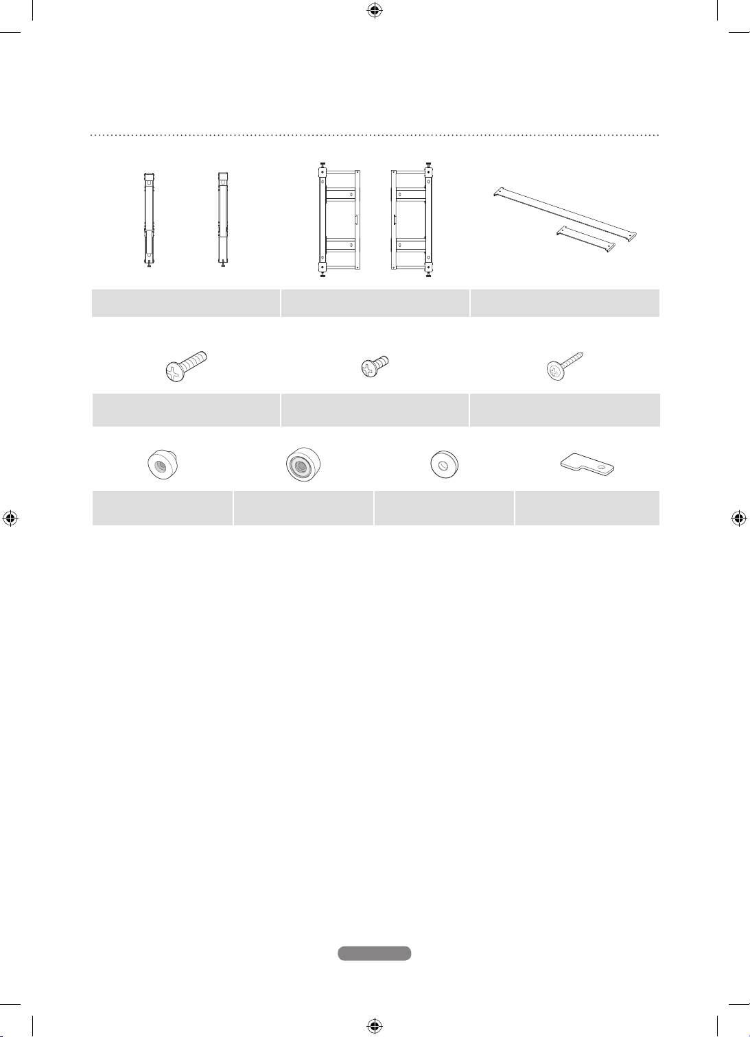
Monitor-mount bracket ⓐ Wall-mount bracket ⓑ Bracket-Bar 400 & 600
Screw ⓐ
(M8 X L30) : 8EA
Screw holder : 4EA
(UE)
Screw holder : 4EA
(UD)
Screw ⓑ
(M4 X L8) : 5EA
Screw holder : 4EA
(ME75)
Wood screw
10EA
Safety fastener : 2EA
2
English
BN68-01537H-00.indb 2 2012-10-29 오후 5:22:59
Page 5

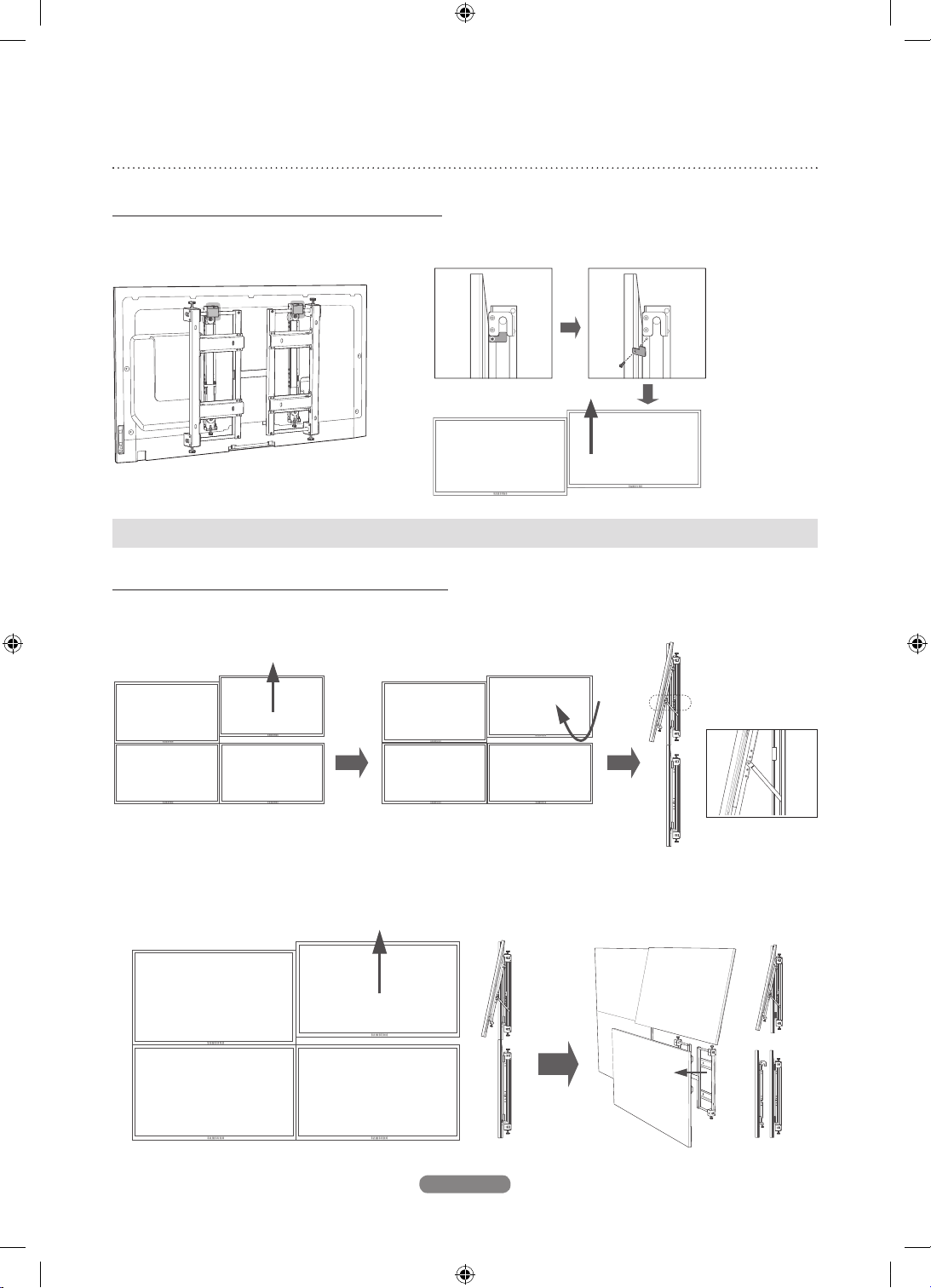
Attaching the bracket ⓐ to the monitor
1. Assemble the four screws ⓐ and the screw holders, and fasten them to x the bracket ⓐ to the monitor as shown in
the picture below.
(M8 X L30)
* Check to conrm that the bracket ⓐ is fastened to the monitor.
MOUNTING ME75
(ME75)
(UE)
(ME75)
N Use the screw holder for UD models when attaching brackets to ME65.
N Use the screw holders for ME75 and UE models when attaching brackets to ME75.
3
English
BN68-01537H-00.indb 3 2012-10-29 오후 5:22:59
Page 6

Mounting the bracket ⓑ onto a wall
1. Using the two screws ⓑ, x bracket bar 400 or 600 according to the product model as shown in the image.
Bracket-Bar 400
2. Fix the bracket ⓑ tightly against the wall using the wood screws.
HOW TO FASTEN A SCREW
1. Make a hole using a
3 X 50 drill.
2. Clean the inside of the
drilled hole.
3. Fasten the wood screw into
the hole.
* When drilling a hole into a wall, make sure
you use a drill bit and drill of the specied
diameter.
Otherwise, there may be safety problems.
* Ensure you check the wall strength, and do the reinforcing work before installation if the wall is not sufciently
strong.
* The provided screws are for wood.
* Check the wall and use proper screws according to the material of the wall, such as marble, steel plate or concrete.
N If it is difcult to fasten the screws into the specic holes, fasten the screws in the adjacent holes.
4
English
BN68-01537H-00.indb 4 2012-10-29 오후 5:23:00
Page 7

Different bracket types by product models and
specications
PRODUCT MODELS AND SPECIFICATIONS
Model VESA Standard Mounting Type Monitor-Mount Bracket Bracket-Bar
LAND 400 400
46UE 400*400
PIVOT 400 400
55UE 400*400
46UD 600*400
55UD 600*400
65ME 400*400
75ME 400*400
LAND 400 400
PIVOT 600 400
LAND 400 600
PIVOT 600 400
LAND 400 600
PIVOT 400 400
LAND 400 400
PIVOT 400 400
LAND 400 400
PIVOT 400 400
CHANGING THE MONITOR-MOUNT BRACKET TYPE FROM 400 TO 600
1. Unfasten the four screws from monitor-mount
bracket type 400 as shown in the image.
2. Extend the bracket and fasten the four screws.
* Use the appropriate bracket type based on the product model and specications.
5
English
BN68-01537H-00.indb 5 2012-10-29 오후 5:23:00
Page 8

INSTALLING THE VIDEO WALL
3
4
1 2
* Before you install on the Video Wall, check the wall strength considering the total weight of the monitors and
brackets you want to install.
Weight of a bracket: 3.2 kg
* If you intend to install on a Video Wall that is four layers or more, take into consideration the air conditioning
system. Consult with an expert before installation as heat from the monitors may cause problems.
N Installing the Video Wall should be done by two persons or more.
6
English
BN68-01537H-00.indb 6 2012-10-29 오후 5:23:00
Page 9

Arranging the monitors
1. Hook the monitor to which the bracket ⓐ is attached on the poles of the wall-mount bracket ⓑ.
* Ensure the hooks are
suspended securely on
the poles.
* Be sure not to put pressure on the panel with your hands when handling the monitor.
Otherwise, you may break the panel.
2. To prevent the monitor from becoming loose, fasten the safety fasteners using the screws ⓑ.
Fasten them on both sides.
(M4 X L8)
* Since the monitor may fall during installation, ensure you fasten the safety fasteners on both sides.
7
English
BN68-01537H-00.indb 7 2012-10-29 오후 5:23:01
Page 10

3. Arrange the monitor on each bracket following steps 1 and 2.
* Be careful not to catch your nger during installation.
Fine tuning
N After arranging the monitors, if they do not seem well-
proportioned, adjust them using the ne-tuning screws
on the brackets.
N Be sure not to leave any height differences or gaps
between the monitors.
1. Correcting height difference between the front and back
of a monitor.
• At the same time, pull the knob and turn the
adjustment screw clockwise.
The monitor will move forward.
To move the monitor backward, turn the screw
counterclockwise.
The ne-tuning screw’s maximum movement range is
5 mm.
<Moving the monitor forward>
Knob
<Moving the monitor backward>
8
English
BN68-01537H-00.indb 8 2012-10-29 오후 5:23:02
Page 11

2. Correcting height difference between upper and lower monitors.
• If you turn the ne-tuning screw on the bottom of the monitor clockwise or counterclockwise, the monitor will move
up or down respectively.
The ne-tuning screw’s maximum movement range is 10 mm.
<Lowering the monitor>
<Raising the monitor>
TO ADJUST THE HEIGHT DIFFERENCE BETWEEN
THE MONITORS ON THE UPPER LAYER,
1. Move upward a monitor and leave enough space to t in your hand below the monitor.
2. Rotate the monitor, unfold the holder attached to the bracket and x the monitor in the holder.
3. Turn the ne-tuning screw to correct the height difference.
4. Repeat steps 1~3 till you obtain the optimum result.
* Be careful not to catch your ngers.
* Ensure the holder is fastened to the wall-mount bracket ⓑ.
* Note that the holder is not compatible with some monitor models.
9
English
Fixing the monitor
in the holder
BN68-01537H-00.indb 9 2012-10-29 오후 5:23:02
Page 12
Detaching the monitors
DETACHING THE UPPER MONITORS
1. Unfasten the screws xing the safety fasteners and lift up the monitors from the video wall.
* Before detaching the monitors, ensure you disconnect all the cables connected to them.
DETACHING THE LOWER MONITORS
1. To detach a monitor, move upward the monitor right above it. Next, rotate and x the moved monitor onto the holder.
Fixing the monitor
in the holder
2. Remove the safety fasteners from the monitor and lift up the monitor to detach it from the video wall as shown in the
picture below.
10
English
BN68-01537H-00.indb 10 2012-10-29 오후 5:23:03
Page 13
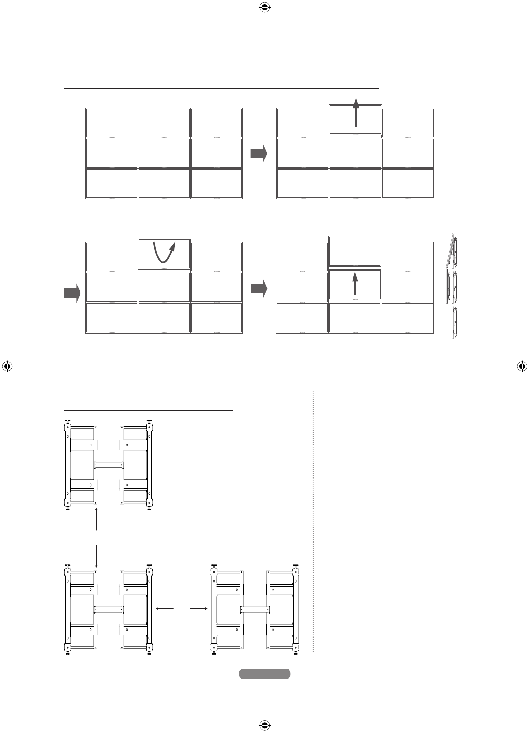
DETACHING THE MIDDLE MONITOR FROM 3X3 VIDEO WALL
1. Move upward the center monitor at the top
row and leave enough space to t in your
hand below the monitor.
2. Rotate and x the center monitor at the top
row onto the holder.
RECOMMENDED DISTANCES BETWEEN
BRACKETS FORMING A MATRIX
ⓐ
ⓑ
3. Move upward the center monitor at the middle row
using the same process as in step 1. Lift and detach
the monitor.
<Recommended distances between
brackets by product model>
ⓐ
460UE LAND 116.8 mm
460UE PIVOT 562.4 mm
550UE LAND 224.5 mm
550UE PIVOT 753.7 mm
UD46A LAND 110.4 mm
UD46A PIVOT 555.7 mm
UD55A LAND 218.1 mm
UD55A PIVOT 747.4 mm
650ME LAND 387.5 mm
750ME LAND 490.6 mm
ⓑ
460UE LAND 507.3 mm
460UE PIVOT 618.6 mm
550UE LAND 698.8 mm
550UE PIVOT 169.6 mm
UD46A LAND 214.0 mm
UD46A PIVOT 55.3 mm
UD55A LAND 405.4 mm
UD55A PIVOT 163.1 mm
650ME LAND 490.6 mm
750ME LAND 1155.2 mm
11
English
BN68-01537H-00.indb 11 2012-10-29 오후 5:23:03
Page 14

Product specications
Dimensions (W x H x D) 533.2 X 538.5 X 43.7 mm / 20.8 X 21.2 X 1.72 inches
Weight 3.2 kg / 0.007 Ibs
VESA standard wall-mount
* For performance improvement, the product’s exterior and specications are subject to change without prior notice.
400 x 400, 600 x 400 mm / 15.75 x 15.75, 23.62 x 15.75 inches
(Compatible with LAND and PIVOT)
12
English
BN68-01537H-00.indb 12 2012-10-29 오후 5:23:04
Page 15

Product drawings
43.7
533.2
538.5
71.0
176.2
176.271.0
VESA POINT x 4EA
417.0 (BRACKET-BAR 600)
137.0 (BRACKET-BAR 400)
109.9
SCREW POINT x 8EA
30.0
249.0
266.6
Bracket-Bar 600
Bracket-Bar 400
15.0
13
English
BN68-01537H-00.indb 13 2012-10-29 오후 5:23:04
Page 16

Contenu
Consignes de sécurité
Consignes de sécurité 01
Introduction
Déballage 02
Fixation du support ⓐ au moniteur 03
Montage du support ⓑ sur le mur 04
Les différents types de xation par modèles de
produit et par spécications 05
Disposition des moniteurs 07
Réglage de précision 08
Détacher les moniteurs 10
Caractéristiques techniques du
produit
Caractéristiques techniques du produit 12
Schémas du produit
Schémas du produit 13
BN68-01537H-00.indb 1 2012-10-29 오후 5:23:04
Page 17

Consignes de sécurité
Français
Les informations contenues dans ce document sont
destinées à préserver votre sécurité et à éviter toute
Ce symbole est utilisé pour insister sur les
instructions qu'il convient de respecter.
perte matérielle.
Veuillez lire attentivement les consignes an d'utiliser
correctement le produit.
* Le non-respect de ces instructions peut donner lieu à de graves blessures, voire entraîner
la mort.
1. Veuillez contacter un spécialiste en montage agréé par votre revendeur pour procéder à l'installation.
• Pour éviter toute risque de blessure, conez l'installation à un professionnel.
Si vous envisagez de déplacer ou de remplacer le
produit après installation, adressez-vous à un spécialiste
en montage agréé par votre revendeur.
Une fois l'installation terminée, n'exercez pas de pression trop forte sur le produit.
2. Veillez à ce que les enfants ne jouent pas à proximité du moniteur.
• Ils risqueraient en effet de se blesser en se cognant la tête ou une autre partie du corps contre les coins du produit.
3. Prenez garde à ce que l'arrière du produit ne heurte pas le mur lorsque vous le faites pivoter ou réglez l'angle.
• Pour éviter d'endommager le mur et le moniteur, vous pouvez xer un morceau d'éponge à chaque coin du moniteur.
4. N'installez pas le moniteur sur un mur dont la solidité est insufsante.
• Le produit risquerait en effet de tomber, d'être endommagé ou de provoquer des dommages corporels.
5. L'installation des moniteurs dans un environnement inhabituel ou extrême peut présenter des problèmes importants
sur le plan des performances. Avant toute installation dans un tel environnement, veuillez contacter un centre de
services Samsung.
• Zones exposées à une quantité excessive de particules nes ou d'humidité, à des produits chimiques, à des
températures extrêmes, à un taux d'humidité élevé, dans des automobiles, etc.
1
Français
BN68-01537H-00.indb 1 2012-10-29 오후 5:23:04
Page 18

Déballage
Support de xation sur le moniteur ⓐ Support de xation murale ⓑ
Vis ⓐ
(M8 X L30) : 8EA
Porte-vis : 4EA
(UE)
Porte-vis : 4EA
(UD)
Vis ⓑ
(M4 X L8) : 5EA
Porte-vis : 4EA
(ME75)
Barre de xation murale,
types 400 et 600
Vis à bois
10EA
Attache de sécurité : 2EA
2
Français
BN68-01537H-00.indb 2 2012-10-29 오후 5:23:04
Page 19

Fixation du support ⓐ au moniteur
1. Assemblez les quatre vis ⓐ avec les porte-vis, puis serrez-les pour xer le support ⓐ au moniteur, comme illustré
ci-dessous.
(M8 X L30)
* Vériez que le support ⓐ est bien xé au moniteur.
MONTAGE DE ME75
(ME75)
(UE)
(ME75)
N Utilisez le support de vis pour modèles UD quand vous installez des xations sur ME65.
N Utilisez les supports de vis pour modèles UE et ME75 quand vous installez des xations sur ME75.
3
Français
BN68-01537H-00.indb 3 2012-10-29 오후 5:23:05
Page 20

Montage du support ⓑ sur le mur
1. À l’aide des deux vis ⓑ, xez la barre de xation 400 ou 600 selon le modèle de produit, comme illustré dans l’image.
Barre de xation 400
2. Fixez solidement le support ⓑ au mur à l’aide des vis à bois.
MÉTHODE DE FIXATION D'UNE VIS
1. Percez un trou à l'aide
d'une mèche 3 X 50.
* Lorsque vous percez un trou dans un mur,
veillez à utiliser une mèche du diamètre
spécié.
Dans le cas contraire, des problèmes peuvent
survenir sur le plan de la sécurité.
* Veuillez vérier la solidité du mur. Si celle-ci s’avère insufsante, procédez aux travaux de consolidation requis
avant le montage.
* Les vis fournies avec le produit sont des vis à bois.
* Vériez le type de matériau du mur (marbre, tôle d’acier, béton, etc.) et utilisez les vis appropriées.
N S’il s’avère difcile d’insérer les vis dans les trous indiqués, utilisez les trous adjacents.
2. Nettoyez l'intérieur du trou.
3. Serrez la vis à bois dans
le trou.
4
Français
BN68-01537H-00.indb 4 2012-10-29 오후 5:23:05
Page 21

Les différents types de xation par modèles de
produit et par spécications
MODÈLES DE PRODUIT ET SPÉCIFICATIONS
Modèle Norme VESA
46UE 400*400
55UE 400*400
46UD 600*400
55UD 600*400
65ME 400*400
75ME 400*400
Type de
montage
PAYSAGE 400 400
PORTRAIT 400 400
PAYSAGE 400 400
PORTRAIT 600 400
PAYSAGE 400 600
PORTRAIT 600 400
PAYSAGE 400 600
PORTRAIT 400 400
PAYSAGE 400 400
PORTRAIT 400 400
PAYSAGE 400 400
PORTRAIT 400 400
Fixation sur moniteur Barre de xation
PASSAGE DE FIXATIONS SUR MONITEUR DE TYPE 400 À 600
1. Desserrez les quatre vis de la xation sur moniteur
de type 400, comme illustré dans l’image.
* Utilisez le type de xation approprié en fonction du modèle de produit et des spécications.
BN68-01537H-00.indb 5 2012-10-29 오후 5:23:05
2. Déployez la xation et xez les quatre vis.
5
Français
Page 22

INSTALLATION DU MUR D'IMAGES
3
4
1 2
* Avant d’installer le Video Wall, vériez la solidité du mur, en tenant compte du poids total des moniteurs et des
supports à installer.
- Poids d’un support : 3,2 kg
* Si vous avez l’intention d’installer un Video Wall constitué d’au moins quatre éléments, l’installation d’un système de
climatisation doit entrer en ligne de compte. Contactez un spécialiste avant le montage, dans la mesure où la chaleur
émise par les moniteurs peut constituer un problème.
N L'installation du Video Wall requiert, au minimum, la présence de deux personnes.
6
Français
BN68-01537H-00.indb 6 2012-10-29 오후 5:23:06
Page 23

Disposition des moniteurs
1. Accrochez le moniteur auquel est xé le support ⓐ aux barres du support de xation murale ⓑ.
* Assurez-vous que
les crochets sont
correctement
accrochés aux barres.
* Veillez à ne pas exercer de pression sur l'écran lors de la manipulation du moniteur.
Vous risqueriez, en effet, de l'endommager.
2. Pour éviter que le moniteur ne se détache, serrez les attaches de sécurité à l'aide des vis ⓑ.
Serrez-les des deux côtés.
(M4 X L8)
* Pour éviter que le moniteur ne tombe au cours de l'installation, prenez soin de serrer les attaches de sécurité des
deux côtés.
7
Français
BN68-01537H-00.indb 7 2012-10-29 오후 5:23:06
Page 24

3. Placez le moniteur sur chaque support en suivant les étapes 1 et 2.
* Prenez garde à ne pas vous coincer les doigts pendant l'installation.
Réglage de précision
N Après avoir disposé les moniteurs, si vous constatez un
problème de positionnement, vous pouvez y remédier à
l’aide des vis de réglage situées sur les supports.
N Il ne doit y avoir aucune différence de hauteur, ni
d’espace entre les moniteurs.
1. Correction de la différence de hauteur entre l’avant et
l’arrière d’un moniteur.
• Tirez le bouton, tout en tournant la vis de réglage dans
le sens des aiguilles d’une montre.
Le moniteur avance.
Pour reculer le moniteur, tournez la vis dans le sens
inverse des aiguilles d’une montre.
L’amplitude maximale de la vis de réglage est de 5 mm.
<Déplacement du moniteur vers l’avant> <Déplacement du moniteur vers l’arrière>
Bouton
8
Français
BN68-01537H-00.indb 8 2012-10-29 오후 5:23:07
Page 25

2. Correction de la différence de hauteur entre les moniteurs supérieurs et inférieurs.
• Selon que vous faites tourner la vis de réglage située au bas du moniteur dans le sens horaire ou antihoraire, le
moniteur monte ou descend.
L’amplitude maximale de la vis de réglage est de 10 mm.
<Réglage du moniteur vers le bas>
<Réglage du moniteur vers le haut>
POUR RÉGLER LA DIFFÉRENCE DE HAUTEUR ENTRE
LES MONITEURS DE LA RANGÉE SUPÉRIEURE :
1. Déplacez un moniteur vers le haut et laissez sufsamment d’espace pour que votre main passe sous le moniteur.
2. Faites pivoter le moniteur, dépliez le support attaché à la xation et xez le moniteur dans le support.
3. Faites tourner la vis de réglage pour corriger la différence de hauteur.
4. Répétez les étapes 1 à 3 jusqu’à ce que vous obteniez le résultat optimum.
* Prenez garde à ne pas vous coincer les doigts !
* Assurez-vous que le support est attaché à la xation murale ⓑ.
* Remarque : le support n’est pas compatible avec certains modèles de moniteurs.
9
Français
Fixation du moniteur
dans le support
BN68-01537H-00.indb 9 2012-10-29 오후 5:23:07
Page 26

Détacher les moniteurs
DÉTACHER LES MONITEURS SUPÉRIEURS
1. Desserrez les vis de xation des attaches de sécurité et retirez les moniteurs du mur d’images en les soulevant.
* Avant de détacher les moniteurs, veillez à débrancher tous les câbles qui y sont connectés.
DÉTACHER LES MONITEURS INFÉRIEURS
1. Pour détacher un moniteur, déplacez le moniteur situé juste au dessus. Ensuite, faites-le pivoter et xez-le sur le
support.
Fixation du moniteur
dans le support
2. Retirez les attaches de sécurité du moniteur et levez ce dernier pour le détacher du mur d’images, comme illustré
ci-dessous.
10
Français
BN68-01537H-00.indb 10 2012-10-29 오후 5:23:08
Page 27

DÉTACHER LE MONITEUR CENTRAL D’UN VIDEO WALL 3X3
1. Déplacez le moniteur central de la rangée
supérieure vers le haut et laissez sufsamment
d’espace pour que votre main passe sous le
moniteur.
2. Faites pivoter le moniteur central de la
rangée supérieure et xez-le sur le support.
DISTANCES RECOMMANDÉES ENTRE LES
FIXATIONS FORMANT UNE MATRICE
ⓐ
ⓑ
3. Déplacez le moniteur central de la rangée du
milieu en suivant la même procédure qu’à
l’étape 1. Soulevez et détachez le moniteur.
<Distances recommandées entre les fixations
par modèle de produit>
ⓐ
460UE PAYSAGE 116,8 mm
460UE PORTRAIT 562,4 mm
550UE PAYSAGE 224,5 mm
550UE PORTRAIT 753,7 mm
UD46A PAYSAGE 110,4 mm
UD46A PORTRAIT 555,7 mm
UD55A PAYSAGE 218,1 mm
UD55A PORTRAIT 747,4 mm
650ME PAYSAGE 387,5 mm
750ME PAYSAGE 490,6 mm
ⓑ
460UE PAYSAGE 507,3 mm
460UE PORTRAIT 618,6 mm
550UE PAYSAGE 698,8 mm
550UE PORTRAIT 169,6 mm
UD46A PAYSAGE 214,0 mm
UD46A PORTRAIT 55,3 mm
UD55A PAYSAGE 405,4 mm
UD55A PORTRAIT 163,1 mm
650ME PAYSAGE 490,6 mm
750ME PAYSAGE 1155,2 mm
11
Français
BN68-01537H-00.indb 11 2012-10-29 오후 5:23:08
Page 28

Caractéristiques techniques du produit
Dimensions (L x P x H) 533,2 X 538,5 X 43,7 mm / 20,8 X 21,2 X 1,72 pouces
Poids 3,2 kg / 0,007 Ibs
400 x 400, 600 x 400 mm /
Fixation murale conforme à la norme VESA
* Dans un souci d’amélioration continue des performances, nous nous réservons le droit de modier les spécications
et l’aspect extérieur du produit sans avis préalable.
15,75 x 15,75, 23,62 x 15,75 pouces
(compatible avec PAYSAGE et PORTRAIT)
12
Français
BN68-01537H-00.indb 12 2012-10-29 오후 5:23:08
Page 29

Schémas du produit
43,7
533,2
538,5
71,0
176,2
176,271,0
VESA POINT x 4EA
417,0 (Barre de fixation 600)
137,0 (
Barre de fixation 400)
109,9
SCREW POINT x 8EA
30,0
249,0
266,6
Barre de fixation 600
Barre de fixation 400
15,0
13
Français
BN68-01537H-00.indb 13 2012-10-29 오후 5:23:09
Page 30

Inhalt
Sicherheitshinweise
Sicherheitshinweise 01
Einleitung
Auspacken 02
Befestigen der Halterung ⓐ am Monitor 03
Montieren der Halterung ⓑ an einer Wand 04
Unterschiedliche Halterungstypen je nach
Gerätemodell und technischen Daten 05
Anordnen der Monitore 07
Exakte Ausrichtung 08
Ausbauen der Monitore 10
Technische Daten des Geräts
Technische Daten des Geräts 12
Produktabbildungen
Produktabbildungen 13
BN68-01537H-00.indb 1 2012-10-29 오후 5:23:09
Page 31

Sicherheitshinweise
Deutsch
Die Information in diesem Handbuch dienen zu Ihrer
Sicherheit und sollen Eigentumsverluste verhindern.
Lesen Sie die Anweisungen genau durch, damit Sie das
Gerät richtig verwenden können.
Dieses Zeichen (Hinweis auf einen sehr
wichtigen Vorgang) wird verwendet, um
darauf hinzuweisen, dass die entsprechenden Anweisungen eingehalten werden
müssen.
* Nichtbeachtung der Anweisungen dieses Handbuchs kann schwere Verletzungen oder den
Tod verursachen.
1. Wenden Sie sich an einen von Ihrem Händler bevollmächtigten Installationsfachmann, der die Installation für
durchführen kann.
• Wenn die Installation nicht durch Fachkräfte erfolgt, können Personenschäden resultieren.
Wenn Sie beabsichtigen, das Gerät nach der Installation
an eine andere Stelle zu bringen oder zu ersetzen, vergessen Sie nicht, einen von Ihrem Händler bevollmächtigten Installationsfachmann einzuschalten.
Üben Sie nach der Installation keine übermäßige Kraft
oder körperlichen Druck auf das Gerät aus.
2. Lassen Sie niemals Ihre Kinder in der Nähe des Geräts spielen.
• Sie könnten mit ihren Kopf oder Körper gegen eine der Ecken des Geräts stoßen und dabei eine Verletzung erleiden.
3. Achten Sie darauf, dass die Rückseite des Geräts nicht gegen die Wand schlägt, wenn Sie es drehen oder den Winkel
einstellen.
• Sie können die Wand und das Gerät vor Schäden schützen, wenn Sie an jeder Ecke des Geräts einen Schwamm
anbringen.
4. Installieren Sie das Gerät nicht an einer Wand, die das Gewicht des Geräts nicht tragen kann.
• Das Gerät könnte herunterfallen und beschädigt werden oder Verletzungen verursachen.
5. Bei Geräten, die in ungewöhnlichen, anormalen oder extremen Bereichen installiert werden, kann es aufgrund der
Umgebungsbedingungen zu gravierenden Leistungsproblemen kommen. Fragen Sie vor der Installation des Geräts in
solch einem Bereich bei einem Samsung Kundendienstcenter nach.
• Gemeint sind hiermit Bereiche, in denen das Gerät übermäßigen Mengen an Feinstaub oder Feuchtigkeit,
Chemikalien, Extremtemperaturen, hoher Luftfeuchtigkeit, vielen Automobilen usw. ausgesetzt ist.
1
Deutsch
BN68-01537H-00.indb 1 2012-10-29 오후 5:23:09
Page 32

Auspacken
Monitor-Halterung ⓐ Wandhalterung ⓑ
Schrauben ⓐ
(M8 X L30) : 8 Stück
Schraubenhalter: 4 Stück
(UE)
Schraubenhalter: 4 Stück
(M4 X L8) : 5 Stück
(UD)
Schrauben ⓑ
Schraubenhalter: 4 Stück
(ME75)
Wandhalterungsleiste Typ
400 und 600
Holzschraube
10 Stück
Sicherheitsbefestigung :
2 Stück
2
Deutsch
BN68-01537H-00.indb 2 2012-10-29 오후 5:23:09
Page 33

Befestigen der Halterung ⓐ am Monitor
1. Ziehen Sie die vier Schrauben ⓐ mit den Schraubenhaltern fest, um die Halterung ⓐ, wie in der nachfolgenden
Abbildung gezeigt, am Monitor zu befestigen.
(M8 X L30)
* Stellen Sie sicher, dass die Halterung ⓐ am Monitor befestigt ist.
BEFESTIGEN AM ME75
(ME75)
(UE)
(ME75)
N Verwenden Sie zum Befestigen von Halterungen am ME65 den Schraubenhalter für UD-Modelle.
N Verwenden Sie zum Befestigen von Halterungen am ME75 die Schraubenhalter für ME75- und UE-Modelle.
3
Deutsch
BN68-01537H-00.indb 3 2012-10-29 오후 5:23:10
Page 34

Montieren der Halterung ⓑ an einer Wand
1. Befestigen Sie die Halterungsleiste 400 oder 600 entsprechend dem Gerätemodell mit den zwei Schrauben ⓑ
(siehe Abbildung).
Halterungsleie 400
2. Befestigen Sie die Halterung ⓑ mit den Holzschrauben sicher an der Wand.
BEFESTIGEN MIT DER SCHRAUBE
1. Bohren Sie mit Hilfe eines
M3-Bohreres ein 50 mm
tiefes Loch in die Wand.
* Wenn Sie ein Loch in eine Wand bohren,
achten Sie darauf, dass Sie einen Bohrer
und einen Bohraufsatz vom angegebenen
Durchmesser verwenden.
Andernfalls kann es zu Sicherheitsproblemen
kommen.
* Prüfen Sie vor der Installation die Festigkeit der Wand und verstärken Sie sie ggf, wenn sie nicht ausreichend fest ist.
* Die mitgelieferten Schrauben sind für Holz geeignet.
* Überprüfen Sie die Wand und verwenden Sie die für das jeweilige Material geeigneten Schrauben
(z. B. für Marmor, Stahlplatten oder Beton).
N Wenn es Schwierigkeiten bereitet, eine bestimmte Schraube in eine bestimmte Bohrung zu versenken, verwenden Sie
für diese Schraube eine benachbarte Bohrung.
2. Reinigen Sie das Innere der
Bohrung.
3. Schrauben Sie die
Holzschraube ins Loch.
4
Deutsch
BN68-01537H-00.indb 4 2012-10-29 오후 5:23:10
Page 35

Unterschiedliche Halterungstypen je nach Gerätemodell und technischen Daten
GERÄTEMODELLE UND TECHNISCHE DATEN
Modell VESA-Standard Befestigungsart Monitor-Wandhalterung Halterungsleiste
QUER 400 400
46UE 400*400
HOCH 400 400
55UE 400*400
46UD 600*400
55UD 600*400
65ME 400*400
75ME 400*400
QUER 400 400
HOCH 600 400
QUER 400 600
HOCH 600 400
QUER 400 600
HOCH 400 400
QUER 400 400
HOCH 400 400
QUER 400 400
HOCH 400 400
WECHSELN DES MONITORMONTAGEHALTERUNGSTYPS VON 400 AUF 600
1. Lösen Sie die vier Schrauben an der
Monitorhalterung 400 (siehe Abbildung).
2. Verlängern Sie die Halterung, und ziehen Sie die
vier Schrauben an.
* Verwenden Sie den für das Gerätemodell und die technischen Daten geeigneten Halterungstyp.
5
Deutsch
BN68-01537H-00.indb 5 2012-10-29 오후 5:23:10
Page 36

INSTALLIEREN DER VIDEOWAND
3
4
1 2
* Ehe Sie die Video Wall installieren, überprüfen Sie die Wandstärke unter Berücksichtigung des Gesamtgewichts der
Monitore und Halterungen, die Sie installieren möchten.
- Gewicht einer Halterung: 3,2 kg
* Wenn Sie vorhaben, eine Video Wall mit 4 oder mehr Reihen zu installieren, achten Sie auf ausreichende
Klimatisierung. Befragen Sie vor der Installation einen Experten, denn die Wärme der Monitore kann Probleme
verursachen.
N Die Installation der Video Wall sollte von mindestens zwei Personen durchgeführt werden.
6
Deutsch
BN68-01537H-00.indb 6 2012-10-29 오후 5:23:11
Page 37

Anordnen der Monitore
1. Haken Sie den Monitor, an dem die Halterung ⓐ montiert ist, an den Säulen der Wandhalterung ⓑ ein.
* Stellen Sie sicher, dass
die Haken fest in die
Säulen eingehängt
sind.
* Achten Sie beim Monitortransport darauf, dass Ihre Hände nicht mit Druck gegen den Bildschirm pressen.
Andernfalls könnten Sie den Bildschirm zerbrechen.
2. Damit sich der Monitor nicht lösen kann, bringen Sie die Sicherheitsbefestigungen mit Hilfe der Schrauben ⓑ an.
Befestigen Sie sie an beiden Seiten.
(M4 X L8)
* Da der Monitor während der Installation hinfallen kann, vergessen Sie nicht, die Sicherheitsbefestigungen auf
beiden Seiten anzubringen.
7
Deutsch
BN68-01537H-00.indb 7 2012-10-29 오후 5:23:11
Page 38

3. Befolgen Sie die Hinweise in Schritt 1 und 2, um den Monitor an den Halterungen anzubringen.
* Achten Sie darauf, dass Sie sich Ihre Finger bei der Installation nicht einklemmen.
Exakte Ausrichtung
N Falls Ihnen die Monitore nach dem Anordnen nicht gut
ausgerichtet erscheinen, können Sie sie mit Hilfe der
Justierschrauben an den Halterungen exakt ausrichten.
N Achten Sie darauf, dass zwischen den Monitoren keine
waagerechten oder senkrechten Fehlausrichtungen
bestehen.
1. Korrigieren eines Höhenunterschieds zwischen der
Vorderseite und Rückseite eines Monitors.
• Ziehen Sie den Knopf heraus und drehen Sie
gleichzeitig die Stellschraube im Uhrzeigersinn.
Der Monitor bewegt sich nach vorne.
Drehen Sie die Schrauben gegen den Uhrzeigersinn, um
den Monitor nach hinten zu bewegen.
Der maximale Bewegungsbereich der Justierschraube
beträgt 5 mm.
<Verschieben des Monitors nach vorn> <Verschieben des Monitors nach hinten>
Knopf
8
Deutsch
BN68-01537H-00.indb 8 2012-10-29 오후 5:23:12
Page 39

2. Korrigieren eines Höhenunterschieds zwischen oberen und unteren Monitoren.
• Wenn Sie die Justierschraube oben am Monitor nach links oder rechts drehen, bewegt sich der Monitor nach unten
bzw. nach oben.
Der maximale Bewegungsbereich der Justierschraube beträgt 10 mm.
<Absenken des Monitors>
<Anheben des Monitors>
SO STELLEN SIE DEN HÖHENUNTERSCHIED ZWISCHEN
DEN MONITOREN DER OBEREN EBENE EIN:
1. Schieben Sie den Monitor nach oben, und lassen Sie darunter so viel Platz, dass Ihre Hand hineinpasst.
2. Drehen Sie den Monitor, klappen Sie den Halter an der Halterung auf, und xieren Sie den Monitor im Halter.
3. Drehen Sie die Justierschraube, bis der Höhenunterschied ausgeglichen ist.
4. Wiederholen Sie die Schritte 1 - 3 solange, bis das Ergebnis optimal ist.
* Achten Sie darauf, dass Sie sich Ihre Finger nicht einklemmen.
* Stellen Sie sicher, dass der Halter an der Wandhalterung ⓑ befestigt ist.
* Beachten Sie, dass die Halterung nicht mit allen Monitormodellen kompatibel ist.
9
Deutsch
Befestigen des
Geräts am Halter
BN68-01537H-00.indb 9 2012-10-29 오후 5:23:12
Page 40

Ausbauen der Monitore
AUSBAUEN DER OBEREN MONITORE
1. Lösen Sie die Schrauben, mit denen die Sicherheitsbefestigungen xiert sind, und ziehen Sie die Monitore nach oben
aus der Videowand heraus.
* Vor dem Ausbauen der Monitore stellen Sie sicher, dass alle daran angeschlossenen Kabel gelöst sind.
AUSBAUEN DER UNTEREN MONITORE
1. Bewegen Sie den Monitor, den Sie ausbauen möchten, und drehen und xieren Sie ihn im Halter.
Befestigen des
Geräts am Halter
2. Entfernen Sie die Sicherheitsbefestigung vom Monitor und heben Sie den Monitor nach oben, um ihn wie im
nachfolgenden Bild gezeigt von der Videowand zu trennen.
10
Deutsch
BN68-01537H-00.indb 10 2012-10-29 오후 5:23:13
Page 41

AUSBAUEN DER MITTLEREN MONITORE EINER 3X3-VIDEO WALL
1. Schieben Sie den mittleren Monitor in der obersten
Reihe nach oben, und lassen Sie darunter so viel
Platz, dass Ihre Hand hineinpasst.
2. Drehen und befestigen Sie den mittleren
Monitor in der oberen Reihe an der
Halterung.
EMPFOHLENE ABSTÄNDE ZWISCHEN
HALTERUNGEN IN FORM EINER MATRIX
ⓐ
ⓑ
Deutsch
3. Schieben Sie den mittleren Monitor in der
mittleren Reihe wie in Schritt 1 beschrieben nach
oben. Heben Sie den Monitor an, und nehmen
Sie ihn ab.
<Empfohlene Abstände zwischen
Halterungen nach Gerätemodell>
ⓐ
460UE QUER 116,8 mm
460UE HOCH 562,4 mm
550UE QUER 224,5 mm
550UE HOCH 753,7 mm
UD46A QUER 110,4 mm
UD46A HOCH 555,7 mm
UD55A QUER 218,1 mm
UD55A HOCH 747,4 mm
650ME QUER 387,5 mm
750ME QUER 490,6 mm
ⓑ
460UE QUER 507,3 mm
460UE HOCH 618,6 mm
550UE QUER 698,8 mm
550UE HOCH 169,6 mm
UD46A QUER 214,0 mm
UD46A HOCH 55,3 mm
UD55A QUER 405,4 mm
UD55A HOCH 163,1 mm
650ME QUER 490,6 mm
750ME QUER 1155,2 mm
11
BN68-01537H-00.indb 11 2012-10-29 오후 5:23:13
Page 42

Technische Daten des Geräts
Abmessungen (B x H x T) 533,2 X 538,5 X 43,7 mm
Gewicht 3,2 kg
Wandhalterung nach VESA-Norm 400 x 400, 600 x 400 mm (kompatibel mit QUER und HOCH)
* Änderungen der technischen Daten und des Aussehens des Geräts vorbehalten.
12
Deutsch
BN68-01537H-00.indb 12 2012-10-29 오후 5:23:13
Page 43

Produktabbildungen
43,7
533,2
538,5
71,0
176,2
176,271,0
VESA POINT x 4EA
417,0 (Halterungsleiste 600)
Halterungsleiste 400)
137,0 (
109,9
SCREW POINT x 8EA
30,0
249,0
266,6
Halterungsleiste 600
Halterungsleiste 400
15,0
13
Deutsch
BN68-01537H-00.indb 13 2012-10-29 오후 5:23:13
Page 44

Indice
Precauzioni di sicurezza
Precauzioni di sicurezza 01
Introduzione
Disimballaggio 02
Montaggio della staffa ⓐ al monitor 03
Montaggio della staffa ⓑ alla parete 04
Tipi diversi di staffa in base ai modelli di
prodotto e alle specifiche 05
Disposizione dei monitor 07
Regolazione 08
Smontaggio dei monitor 10
Specifiche del prodotto
Specifiche del prodotto 12
Diagrammi del prodotto
Diagrammi del prodotto 13
BN68-01537H-00.indb 1 2012-10-29 오후 5:23:14
Page 45

Precauzioni di sicurezza
Le informazioni qui contenute riguardano la sicurezza
dell’utente e la prevenzione di eventuali danni.
Leggere attentamente le istruzioni allo scopo di utilizzare il prodotto in modo corretto.
* La mancata osservanza delle istruzioni qui riportate può causare lesioni gravi perfino
mortali.
1. Per l’installazione, rivolgersi a un installatore autorizzato.
• Se non eseguita da un tecnico professionista, una errata installazione del prodotto può causare lesioni personali.
Questo simbolo obbligatorio viene utilizzato per sottolineare l’importanza delle
istruzioni che devono essere assolutamente osservate.
Italiano
In caso di riposizionamento o sostituzione del prodotto
dopo l’installazione, consultare un installatore autorizzato.
2. Non far giocare i bambini nei pressi del prodotto.
• Potrebbero riportare lesioni urtando gli angoli del prodotto.
3. Prestare attenzione a non lasciare che il retro del prodotto colpisca la parete durante la rotazione o la regolazione
dell’angolo.
• E’ possibile proteggere la parete e il prodotto da eventuali danni fissando un tampone in spugna in corrispondenza di
ogni angolo del prodotto.
4. Non installare il prodotto su una parete non sufcientemente solida da supportare il peso del prodotto.
• Il prodotto potrebbe cadere, riportando danni o causando lesioni personali.
5. I prodotti installati in aree anomale, anormali o soggette a condizioni estreme possono essere soggetti a problemi
prestazionali a causa dell’ambiente circostante. Rivolgersi a un centro di assistenza Samsung prima di installare il
prodotto in tali aree.
• Aree esposte a una quantità eccessiva di polvere o umidità, sostanze chimiche, temperature estreme, vapore,
passaggio di veicoli, ecc.
Dopo l’installazione, non applicare una forza o una
pressione eccessiva sul prodotto.
1
Italiano
BN68-01537H-00.indb 1 2012-10-29 오후 5:23:14
Page 46

Disimballaggio
Staffa per il montaggio del monitor ⓐ Staffa per il montaggio a parete ⓑ
Vite ⓐ
(M8 X L30) : 8EA
Supporto vite: 4EA
(UE)
Supporto vite: 4EA
(UD)
Vite ⓑ
(M4 X L8) : 5EA
Supporto vite: 4EA
(ME75)
Tipo di staffa per montaggio a parete
da 400 e 600
Vite da legno
10EA
Dispositivo di sicurezza :
2EA
2
Italiano
BN68-01537H-00.indb 2 2012-10-29 오후 5:23:14
Page 47

Montaggio della staffa ⓐ al monitor
1. Assemblare le quattro viti ⓐ e il supporto vite, quindi serrarli per fissare la staffa ⓐ al monitor come mostrato nella
figura sottostante.
(M8 X L30)
* Verificare che la staffa ⓐ sia fissata saldamente al monitor.
MONTAGGIO DI ME75
(ME75)
(UE)
(ME75)
N Utilizzare la rondella per modelli UD quando si ssano le staffe a ME65.
N Utilizzare le rondelle per modelli ME75 e UE quando si ssano le staffe a ME75.
3
Italiano
BN68-01537H-00.indb 3 2012-10-29 오후 5:23:15
Page 48

Montaggio della staffa ⓑ alla parete
1. Utilizzando le due viti ⓑ, ssare la staffa da 400 o 600 a seconda del modello di prodotto, come mostrato
nell’immagine.
Staa 400
2. Fissare saldamente la aa ⓑ alla parete utilizzando le viti da legno fornite.
ISTRUZIONI PER IL CORRETTO
MONTAGGIO DELLE VITI
1. Eseguire un foro con il
trapano usando una punta
da 3 X 50.
* Quando si esegue un foro in una parete,
usare sempre una punta da trapano del
diametro specificato.
In caso contrario, potrebbero verificarsi
problemi di sicurezza.
* Verificare la solidità della parete; se la parete è debole, consolidarla prima di installare il prodotto.
* Le viti fornite sono da legno.
* Verificare la parete sulla quale verrà fissato il prodotto e utilizzare viti appropriate in base al materiale di cui è
composta la parete, per esempio marmo, pannelli d’acciaio o calcestruzzo.
N Se risulta difficile avvitare le viti nei fori specifici, avvitarle nei fori adiacenti.
2. Pulire l’interno del foro.
3. Inserire la vite da legno
all’interno del foro e
serrarla.
4
Italiano
BN68-01537H-00.indb 4 2012-10-29 오후 5:23:15
Page 49

Tipi diversi di staffa in base ai modelli di prodotto e
alle speciche
MODELLI DI PRODOTTO E SPECIFICHE
Modello Standard VESA Tipo di montaggio Staffa per montaggio del monitor Staffa
ORIZZONTALE 400 400
46UE 400*400
VERTICALE 400 400
55UE 400*400
46UD 600*400
55UD 600*400
65ME 400*400
75ME 400*400
ORIZZONTALE 400 400
VERTICALE 600 400
ORIZZONTALE 400 600
VERTICALE 600 400
ORIZZONTALE 400 600
VERTICALE 400 400
ORIZZONTALE 400 400
VERTICALE 400 400
ORIZZONTALE 400 400
VERTICALE 400 400
MODIFICA DEL TIPO DI STAFFA PER MONTAGGIO DEL
MONITOR DA 400 A 600
1. Svitare le quattro viti del tipo di staffa per montaggio
del monitor da 400, come mostrato nell’immagine.
2. Allungare la staffa e serrare le quattro viti.
* Utilizzare il tipo di staffa corretto in base al modello di prodotto e alle speciche.
5
Italiano
BN68-01537H-00.indb 5 2012-10-29 오후 5:23:15
Page 50

INSTALLAZIONE DEL VIDEO WALL
3
4
1 2
* Prima di installare il Video Wall, verificare la solidità della parete considerando il peso totale dei monitor e delle
staffe da installare.
- Peso di una staffa: 3,2 kg
* Se si intende installare un Video Wall a quattro o più file, prendere in considerazione l’adozione di un sistema di
condizionamento. Consultare un esperto prima di eseguire l’installazione poiché il calore generato dai monitor
potrebbe creare problemi.
N L’installazione del Video Wall deve essere effettuata da due o più persone.
6
Italiano
BN68-01537H-00.indb 6 2012-10-29 오후 5:23:15
Page 51

Disposizione dei monitor
1. Agganciare il monitor al quale la staffa ⓐ è fissata ai rispettivi poli della staffa a parete ⓑ.
* Verificare che i ganci
siano saldamente
ancorati ai poli.
* Non premere con le mani sul pannello durante la manipolazione del monitor.
In caso contrario, il pannello potrebbe rompersi.
2. Per evitare che il monitor si allenti, serrare i dispositivi di sicurezza utilizzando le viti ⓑ.
Serrarli su entrambi i lati.
(M4 X L8)
* Poiché il monitor potrebbe cadere durante l’installazione, serrare i dispositivi di sicurezza su entrambi i lati.
7
Italiano
BN68-01537H-00.indb 7 2012-10-29 오후 5:23:16
Page 52

3. Disporre il monitor sulle staffe seguendo i passaggi 1 e 2.
* Prestare attenzione a non incastrarsi le dita durante l’installazione.
Regolazione
N Dopo la disposizione dei monitor, nel caso le proporzioni
non risultassero adeguate, è possibile effettuare una
regolazione utilizzando le apposite viti sulle staffe.
N Fare attenzione a non lasciare differenze nell’altezza o
intercapedini tra i monitor.
1. Regolazione della differenza di altezza tra la parte
anteriore e quella posteriore di un monitor.
• Contemporaneamente, tirare la manopola e ruotare la
vite di regolazione in senso orario.
Il monitor si sposterà in avanti.
Per spostare il monitor indietro, ruotare la vite di
regolazione in senso antiorario.
L’ampiezza massima della regolazione è di 5 mm.
<Spostamento in avanti del monitor> <Spostamento indietro del monitor>
Manopola
8
Italiano
BN68-01537H-00.indb 8 2012-10-29 오후 5:23:17
Page 53

2. Regolazione della differenza di altezza tra monitor inferiori e superiori.
• Ruotando la vite di regolazione sul fondo del monitor in senso orario o antiorario, il monitor si sposterà
rispettivamente verso l’alto o verso il basso.
L’ampiezza massima della regolazione è di 10 mm.
<Abbassamento del monitor>
<Sollevamento del monitor>
PER REGOLARE LA DIFFERENZA DI ALTEZZA DEI
MONITOR SULLA FILA SUPERIORE,
1. Sollevare uno dei monitor e lasciare abbastanza spazio per infilare la mano al di sotto di esso.
2. Ruotare il monitor, raddrizzare il supporto vite ssato alla staffa e ssare il monitor al supporto.
3. Ruotare la vite di regolazione per correggere la differenza di altezza.
4. Ripetere i passaggi 1~3 no a ottenere il risultato ottimale.
* Prestare attenzione a non incastrarsi le dita.
* Verificare che i supporti siano saldamente fissati alla staffa per il montaggio a parete ⓑ.
* Si noti che il sostegno non è compatibile con alcuni modelli di monitor.
9
Italiano
Fissaggio del
monitor al supporto
vite
BN68-01537H-00.indb 9 2012-10-29 오후 5:23:17
Page 54

Smontaggio dei monitor
SMONTAGGIO DEI MONITOR SUPERIORI
1. Svitare le viti ssando i dispositivi di sicurezza e sollevare i monitor dal video wall.
* Prima di smontare i monitor dalla struttura, scollegare tutti i cavi a loro connessi.
SMONTAGGIO DEI MONITOR INFERIORI
1. Per scollegare uno dei monitor, sollevare il monitor al di sopra di esso, quindi ruotare il monitor spostato e ssarlo al
sostegno.
Fissaggio del
monitor al supporto
vite
2. Rimuovere i dispositivi di sicurezza dal monitor e sollevare il monitor per separarlo dal video wall come mostrato nella
gura sottostante.
10
Italiano
BN68-01537H-00.indb 10 2012-10-29 오후 5:23:18
Page 55

SMONTAGGIO DEL MONITOR CENTRALE IN UNA STRUTTURA VIDEO WALL 3X3
1. Sollevare il monitor centrale della la superiore
e lasciare abbastanza spazio per inlare la
mano al di sotto di esso.
2. Ruotare il monitor centrale della la
superiore e ssarlo al sostegno.
3. Sollevare il monitor centrale della la di mezzo
attenendosi alla stessa procedura mostrata alla
fase 1; sollevare e scollegare il monitor.
DISTANZE CONSIGLIATE TRA LE STAFFE CHE
FORMANO UNA MATRICE
ⓐ
ⓑ
<Distanze consigliate tra le staffe in
base al modello di prodotto>
ⓐ
460UE ORIZZONTALE 116,8 mm
460UE VERTICALE 562,4 mm
550UE ORIZZONTALE 224,5 mm
550UE VERTICALE 753,7 mm
UD46A ORIZZONTALE 110,4 mm
UD46A VERTICALE 555,7 mm
UD55A ORIZZONTALE 218,1 mm
UD55A VERTICALE 747,4 mm
650ME ORIZZONTALE 387,5 mm
750ME ORIZZONTALE 490,6 mm
ⓑ
460UE ORIZZONTALE 507,3 mm
460UE VERTICALE 618,6 mm
550UE ORIZZONTALE 698,8 mm
550UE VERTICALE 169,6 mm
UD46A ORIZZONTALE 214,0 mm
UD46A VERTICALE 55,3 mm
UD55A ORIZZONTALE 405,4 mm
UD55A VERTICALE 163,1 mm
650ME ORIZZONTALE 490,6 mm
750ME ORIZZONTALE 1155,2 mm
11
Italiano
BN68-01537H-00.indb 11 2012-10-29 오후 5:23:18
Page 56

Speciche del prodotto
Dimensioni (L x A x P) 533,2 X 538,5 X 43,7 mm
Peso 3,2 kg
Montaggio a parete VESA standard
* Al ne di migliorare le prestazioni, le speciche e la struttura esterna del prodotto sono soggette a modiche senza
preavviso.
400 x 400, 600 x 400 mm
(Compatibile con orientamento ORIZZONTALE e VERTICALE)
12
Italiano
BN68-01537H-00.indb 12 2012-10-29 오후 5:23:18
Page 57

Diagrammi del prodotto
43,7
533,2
538,5
71,0
176,2
176,271,0
VESA POINT x 4EA
417,0 (Staffa 600)
Staffa 400)
137,0 (
SCREW POINT x 8EA
30,0
109,9
249,0
266,6
Staffa 600
Staffa 400
15,0
13
Italiano
BN68-01537H-00.indb 13 2012-10-29 오후 5:23:19
Page 58

Tartalom
Biztonsági óvintézkedések
Biztonsági óvintézkedések 01
Bevezetés
Kicsomagolás 02
Az ⓐ tartókeret felszerelése a monitorra 03
A ⓑ keret rögzítése a falhoz 04
A különböző típusú konzolok készüléktípus
szerint és azok jellemzői 05
A monitorok elhelyezése 07
Finombeállítás 08
A monitorok szétszerelése 10
Műszaki jellemzők
Műszaki jellemzők 12
Készülékrajzok
Készülékrajzok 13
BN68-01537H-00.indb 1 2012-10-29 오후 5:23:19
Page 59

Biztonsági óvintézkedések
Az itt megadott adatok a felhasználók biztonságát és az
anyagi károk elkerülését szolgálják.
Ez a jel a feltétlenül betartandó utasításo-
kat jelöli.
Kérjük, gyelmesen olvassa el az utasításokat, és azoknak megfelelően használja a készüléket.
* Amennyiben nem tartja be az útmutatóban foglalt utasításokat, súlyos sérülés vagy akár
haláleset is bekövetkezhet.
1. A felszereléshez feltétlenül vegye igénybe a forgalmazó által felhatalmazott szakember segítségét.
• A készülék szakszerűtlen felszerelése miatt személyi sérülés következhet be.
Ha a felszerelés után át kívánja helyezni, vagy ki kívánja
cserélni a készüléket, feltétlenül vegye igénybe a forgalmazó által felhatalmazott szakember segítségét.
2. Ügyeljen rá, hogy gyermekek ne játszanak a készülék közelében.
• Beverhetik a fejüket, vagy nekimehetnek a készülék sarkának, és megsérülhetnek.
Felszerelés után ne fejtsen ki erőt vagy nyomást a
készülékre.
Magyar
3. Vigyázzon, hogy elfordításkor vagy a szög beállításakor a készülék hátulja ne ütődjön neki a falnak.
• A falat és a készüléket is megvédheti a sérülésektől, ha egy darab szivacsot helyez a készülék sarkaira.
4. Ne szerelje fel a készüléket olyan falfelületre, amely nem bírja el a készülék súlyát.
• A készülék leeshet, és megrongálódhat vagy személyi sérülést okozhat.
5. A szokatlan, rendkívüli vagy szélsőséges helyekre felszerelt készülékek esetében előfordulhat, hogy a körülmények
miatt súlyos teljesítményromlás tapasztalható. Mielőtt felszerelné a készüléket egy ilyen helyre, kérje a Samsung
szervizközpont segítségét.
• Túlzott mennyiségű nompornak vagy nedvességnek, vegyszereknek, szélsőséges hőmérsékletnek, magas
páratartalomnak kitett helyek, gépkocsi stb.
1
Magyar
BN68-01537H-00.indb 1 2012-10-29 오후 5:23:19
Page 60

Kicsomagolás
ⓐ monitortartó keret ⓑ fali tartókeret
Csavar ⓐ
(M8 X L30) : 8 db
Távtartó: 4 db
(UE)
Távtartó: 4 db
(UD)
Csavar ⓑ
(M4 X L8) : 5 db
Távtartó: 4 db
(ME75)
Falikonzol-lemez, 400-as és 600-as
típus
Facsavar
10 db
Biztonsági rögzítőelem :
2 db
2
Magyar
BN68-01537H-00.indb 2 2012-10-29 오후 5:23:19
Page 61

Az ⓐ tartókeret felszerelése a monitorra
1. Szerelje össze a négy ⓐ csavart és a távtartókat, majd a segítségükkel erősítse az ⓐ keretet a monitorhoz az alábbi
képen látható módon.
(M8 X L30)
* Ellenőrizze, hogy az ⓐ keret megfelelően hozzá van-e erősítve a monitorhoz.
AZ ME75 RÖGZÍTÉSE
(ME75)
(UE)
(ME75)
N A konzolok ME65 típusú készülékhez való rögzítésekor használja az UD típusokhoz mellékelt csavartartót.
N A konzolok ME75 típusú készülékhez való rögzítésekor használja az ME75 és UE típusokhoz mellékelt csavartartót.
3
Magyar
BN68-01537H-00.indb 3 2012-10-29 오후 5:23:20
Page 62

A ⓑ keret rögzítése a falhoz
1. A készülék típusától függően az ábrán látható módon használja a két ⓑ csavart, illetve 400-as vagy 600-as típusú fali
konzolt.
Konzollemez 400
2. A facsavarok segítségével szorosan erősítse a falhoz a ⓑ keretet.
A CSAVAROK RÖGZÍTÉSE
1. 3 x 50-es fúróval fújon egy
lyukat.
2. Tisztítsa ki a kifúrt lyuk
belsejét.
3. Rögzítse a facsavart a
lyukba.
* Amikor lyukat fúr a falba, ügyeljen rá, hogy
megfelelő átmérőjű fúrószárat használjon.
Ennek elmulasztása biztonsági problémákat
vonhat maga után.
* Feltétlenül ellenőrizze a fal vastagságát, és ha a fal nem elég erős, a monitor felszerelése előtt erősítse meg azt.
* A mellékelt csavarok fa felülethez valók.
* Ellenőrizze a falat, és a fal anyagának (pl. márvány, acéllemez vagy beton) megfelelő csavarokat használjon.
N Ha egy csavar adott lyukba történő rögzítése nehézséget okoz, próbálja a csavart a szomszédos lyukba rögzíteni.
4
Magyar
BN68-01537H-00.indb 4 2012-10-29 오후 5:23:20
Page 63

A különböző típusú konzolok készüléktípus szerint
és azok jellemzői
KÉSZÜLÉKTÍPUSOK ÉS JELLEMZŐK
Típus VESA szabvány Rögzítés típusa Monitorra szerelt konzol Konzollemez
FEKVŐ 400 400
46UE 400*400
ÁLLÓ 400 400
55UE 400*400
46UD 600*400
55UD 600*400
65ME 400*400
75ME 400*400
FEKVŐ 400 400
ÁLLÓ 600 400
FEKVŐ 400 600
ÁLLÓ 600 400
FEKVŐ 400 600
ÁLLÓ 400 400
FEKVŐ 400 400
ÁLLÓ 400 400
FEKVŐ 400 400
ÁLLÓ 400 400
A MONITORRA SZERELT KONZOL 400-ASRÓL 600-AS TÍPUSÚRA
MÓDOSÍTÁSA
1. Lazítsa meg a 400-as típusú monitorra szerelt
konzol négy csavarját az ábrán látható módon.
2. Húzza ki a konzolt, majd húzza meg a négy csavart.
* Használja a készülék típusának és jellemzőinek megfelelő típusú konzolt.
5
Magyar
BN68-01537H-00.indb 5 2012-10-29 오후 5:23:21
Page 64

A VIDEOFAL FELSZERELÉSE
3
4
1 2
* A Video Wall felszerelése előtt a felszerelni kívánt monitorok és rögzítőkeretek összsúlyát gyelembe véve
ellenőrizze, hogy elég erős-e a fal.
- Egy darab rögzítőkeret súlya: 3,2 kg
* Ha négy vagy több szintből álló Video Wall konstrukciót kíván felszerelni, gondoskodjon megfelelő
légkondicionálásról. Felszerelés előtt kérje ki szakértő véleményét, mivel a monitorok által kibocsátott hő gondot
okozhat.
N A Video Wall felszereléséhez legalább két személy szükséges.
6
Magyar
BN68-01537H-00.indb 6 2012-10-29 오후 5:23:21
Page 65

A monitorok elhelyezése
1. Akassza be az ⓐ kerethez rögzített monitort a ⓑ fali rögzítőkeret függőleges oszlopaiba.
* Bizonyosodjon
meg róla, hogy a
kampók szilárdan
rögzítve legyenek az
oszlopokon.
* A monitor felszerelése közben ne gyakoroljon nyomást a kezével a panelra.
A panel eltörhet.
2. A monitor meglazulásának elkerülése érdekében a ⓑ csavarok segítségével szerelje fel a biztonsági rögzítőelemeket.
Minkét oldalon rögzítse őket.
(M4 X L8)
* Mivel a monitor felszerelés közben leeshet, minkét oldalon rögzítse a biztonsági rögzítőelemeket.
7
Magyar
BN68-01537H-00.indb 7 2012-10-29 오후 5:23:21
Page 66

3. Az 1–2. lépést követve szerelje fel az összes kerettel ellátott monitort.
* Ügyeljen, felszerelés közben nehogy becsípje az ujját.
Finombeállítás
N Ha úgy tűnik, hogy a monitorok elrendezése nem
egyenletes, a kereteken található nombeállító csavarok
segítségével igazítsa meg őket.
N A monitorok között ne legyen szintbeli különbség vagy
rés.
1. A monitor elő- és hátlapja közötti magasságkülönbség
korrigálása.
• Egyszerre húzza meg a gombot és forgassa el az
állítócsavart az óramutató járásával megegyező irányba.
A monitor előrefelé mozdul el. A csavart az ellenkező
irányba forgatva a monitor hátrafelé mozdul el.
A nombeállító csavar maximális mozgási tartománya
5 mm.
<A monitor mozgatása előrefelé>
Gomb
<A monitor mozgatása hátrafelé>
8
Magyar
BN68-01537H-00.indb 8 2012-10-29 오후 5:23:22
Page 67

2. Az alsó és felső szinteken található monitorok közötti magasságkülönbség korrigálása
• Ha elfordítja a monitor alján lévő nombeállító csavart az óramutató járásával megegyező vagy ellentétes irányba, a
monitor annak megfelelően elmozdul felfelé vagy lefelé.
A nombeállító csavar maximális mozgási tartománya 10 mm.
<A monitor lesüllyesztése>
<A monitor megemelése>
A FELSŐ SZINTEN LÉVŐ MONITOROK MAGASSÁGÁNAK
KORRIGÁLÁSA:
1. Emeljen fel egy monitort, és hagyjon akkora helyet a monitor alatt, hogy keze beférjen.
2. Fordítsa el a monitort, hajtsa ki a kerethez erősített tartóelemet, és rögzítse a monitort a tartóelemhez.
3. A magasságkülönbség korrigálásához fordítsa el a nombeállító csavart.
4. Addig ismételje az 1–3 lépést, amíg el nem éri a kívánt eredményt.
* Ügyeljen, nehogy becsípje az ujját.
* Ellenőrizze, hogy a tartóelem rögzítve van-e a ⓑ jelű falikonzolhoz.
* Figyelem! A tartó egyes monitortípusokkal nem kompatibilis.
9
Magyar
A monitor rögzítése
a tartóelemhez
BN68-01537H-00.indb 9 2012-10-29 오후 5:23:22
Page 68

A monitorok szétszerelése
A FELSŐ MONITOROK LESZERELÉSE
1. Lazítsa meg a biztonsági rögzítőelemeket tartó csavarokat, és emelje ki a monitorokat a videofalból.
* A monitorok szétszerelése előtt húzza ki az összes hozzájuk csatlakoztatott kábelt.
AZ ALSÓ MONITOROK LESZERELÉSE
1. Egy monitor leszereléséhez emelje fel a közvetlenül fölötte lévő monitort. Ezután fordítsa ki, majd rögzítse a felemelt
monitort a tartón.
A monitor rögzítése
a tartóelemhez
2. Távolítsa el a biztonsági rögzítőelemet a monitorról, és a videofalból történő kiemeléshez emelje fel a monitort az
alábbi ábrán látható módon.
10
Magyar
BN68-01537H-00.indb 10 2012-10-29 오후 5:23:23
Page 69

A KÖZÉPSŐ MONITOR ELTÁVOLÍTÁSA A 3 X 3-AS VIDEO WALL
KONSTRUKCIÓBÓL
1. Emelje fel a felső sorban lévő középső
monitort, elegendő helyet hagyva, hogy keze
beférjen a monitor alá.
2. Fordítsa ki a felső sor középső monitorát,
majd rögzítse a tartón.
3. Emelje fel a középső sor középső monitorát az
1. lépésnél leírt módon. Emelje fel, majd vegye
le a monitort.
A RÁCS ALAKZATBAN ELHELYEZETT KONZOLOK
KÖZÖTTI JAVASOLT TÁVOLSÁG
ⓐ
ⓑ
<A konzolok közötti javasolt
távolságok készüléktípus szerint>
ⓐ
460UE FEKVŐ 116,8 mm
460UE ÁLLÓ 562,4 mm
550UE FEKVŐ 224,5 mm
550UE ÁLLÓ 753,7 mm
UD46A FEKVŐ 110,4 mm
UD46A ÁLLÓ 555,7 mm
UD55A FEKVŐ 218,1 mm
UD55A ÁLLÓ 747,4 mm
650ME FEKVŐ 387,5 mm
750ME FEKVŐ 490,6 mm
ⓑ
460UE FEKVŐ 507,3 mm
460UE ÁLLÓ 618,6 mm
550UE FEKVŐ 698,8 mm
550UE ÁLLÓ 169,6 mm
UD46A FEKVŐ 214,0 mm
UD46A ÁLLÓ 55,3 mm
UD55A FEKVŐ 405,4 mm
UD55A ÁLLÓ 163,1 mm
650ME FEKVŐ 490,6 mm
750ME FEKVŐ 1155,2 mm
11
Magyar
BN68-01537H-00.indb 11 2012-10-29 오후 5:23:24
Page 70

Műszaki jellemzők
Méretek (Sz x Ma x Mé) 533,2 X 538,5 X 43,7 mm
Súly 3,2 kg
VESA-szabványnak megfelelő falikonzol
* A teljesítmény javítása érdekében a készülék külseje és műszaki jellemzői előzetes értesítés nélkül
megváltozhatnak.
400 x 400, 600 x 400 mm
(FEKVŐ és ÁLLÓ elrendezésű konzolokkal is használható)
12
Magyar
BN68-01537H-00.indb 12 2012-10-29 오후 5:23:24
Page 71

Készülékrajzok
43,7
533,2
538,5
71,0
176,2
176,271,0
VESA POINT x 4EA
417,0 (Konzollemez 600)
Konzollemez 400)
137,0 (
SCREW POINT x 8EA
30,0
109,9
249,0
266,6
Konzollemez 600
Konzollemez 400
15,0
13
Magyar
BN68-01537H-00.indb 13 2012-10-29 오후 5:23:24
Page 72

Spis treści
Zasady bezpieczeństwa
Zasady bezpieczeństwa 01
Wprowadzenie
Rozpakowywanie 02
Mocowanie uchwytu ⓐ do monitora 03
Mocowanie uchwytu ⓑ na ścianie 04
Różne typy wsporników wg modeli
produktów i parametrów 05
Ułożenie monitorów 07
Regulacja precyzyjna 08
Odłączanie monitorów 10
Specykacja produktu
Specykacja produktu 12
Schemat produktu
Schemat produktu 13
BN68-01537H-00.indb 1 2012-10-29 오후 5:23:24
Page 73

Zasady bezpieczeństwa
Informacje zawarte w niniejszym dokumencie służą zachowaniu bezpieczeństwa i uniknięciu utraty własności.
Podany znak służy podkreśleniu konieczno-
ści postępowania według instrukcji.
Aby korzystać z produktu w prawidłowy sposób, należy
dokładnie zapoznać się z instrukcjami.
* Niedostosowanie się do niniejszych instrukcji może spowodować poważne obrażenia lub
śmierć.
1. W celu instalacji produktu, skontaktuj się z instalatorem autoryzowanym przez sprzedawcę.
• Instalacja wykonana przez osobę nie będącą profesjonalistą może spowodować uszkodzenie ciała.
Jeśli planujesz zmienić miejsce montażu lub wymianę
produktu, skontaktuj się z instalatorem autoryzowanym
przez sprzedawcę.
2. Nie wolno pozwalać dzieciom na zabawę w pobliżu urządzenia.
• Podczas zabawy mogą uderzyć głową lub inną częścią ciała o krawędź produktu i odnieść obrażenia.
Po instalacji nie należy używać nadmiernej siły lub zycznego nacisku w stosunku do produktu.
Polski
3. Upewnij się, że tylna część urządzenia nie uderzy w ścianę podczas obracania lub regulacji kąta.
• Ścianę i urządzenie można ochronić przed uszkodzeniem poprzez doklejenie kawałka gąbki do każdego z rogów
urządzenia.
4. Produktu nie należy instalować na ścianie, która nie jest w stanie wytrzymać wagi urządzenia.
• Upadek może spowodować uszkodzenie urządzenia lub kontuzję.
5. Instalacja w nietypowych, niewłaściwych lub ekstremalnych środowiskach może spowodować poważne problemy w
funkcjonowaniu produktu związane z otoczeniem. Przed instalacją urządzenia w takim środowisku skonsultuj się z
centrum serwisowym rmy Samsung.
• Obszary narażone na nadmierną ilość drobnych cząstek, wilgotność, ekstremalne temperatury, wysoką wilgotność,
spaliny, itp.
1
Polski
BN68-01537H-00.indb 1 2012-10-29 오후 5:23:24
Page 74

Rozpakowywanie
Uchwyt wspornika monitora ⓐ Uchwyt wspornika naściennego ⓑ
Wkręt ⓐ
(M8 X L30) : 8EA
Obejma do wkrętów: 4EA
(UE)
Obejma do wkrętów: 4EA
(UD)
Wkręt ⓑ
(M4 X L8) : 5EA
Obejma do wkrętów: 4EA
(ME75)
Belka wspornika do montażu
naściennego typu 400 i 600
Wkręt do drewna
10EA
Blaszka zabezpieczająca :
2EA
2
Polski
BN68-01537H-00.indb 2 2012-10-29 오후 5:23:25
Page 75

Mocowanie uchwytu ⓐ do monitora
1. Połącz cztery wkręty ⓐ z obejmami, następnie dokręć je, aby przytwierdzić uchwyt ⓐ do monitora jak pokazano na
poniższym rysunku.
(M8 X L30)
* Upewnij się, że uchwyt ⓐ jest prawidłowo przytwierdzony do monitora.
MONTAŻ W PRZYPADKU MODELU ME75
(ME75)
(UE)
(ME75)
N Użyć uchwytu śruby do modeli UD podczas mocowania wsporników do modelu ME65.
N Użyć uchwytu śruby do modeli ME75 i UE podczas mocowania wsporników do modelu ME75.
3
Polski
BN68-01537H-00.indb 3 2012-10-29 오후 5:23:25
Page 76

Mocowanie uchwytu ⓑ na ścianie
1. Za pomocą dwóch śrub ⓑ zamocować belkę poprzeczną typu 400 lub 600 (w zależności od modelu produktu), tak jak
pokazano na ilustracji.
Belka poprzeczna 400
2. Dokładnie przytwierdź uchwyt ⓑ do ściany za pomocą wkrętów do drewna.
JAK DOKRĘCAĆ WKRĘTY
1. Wykonaj otwór za pomocą
wiertła 3 x 50.
2. Wyczyść wnętrze
wywierconego otworu.
3. Dokręć wkręt do drewna w
otworze.
* Do wiercenia otworu w ścianie należy użyć
odpowiedniego wiertła o właściwej średnicy.
W przeciwnym razie mogą wystąpić problemy
z bezpieczeństwem.
* Upewnij się, że ściana jest wystarczająco wytrzymała. W razie konieczności wzmocnij ścianę przed instalacją.
* Wkręty w zestawie przeznaczone są do drewna.
* Upewnij się, że używane wkręty są dostosowane do budulca ściany, np. marmuru, płyty stalowej lub betonu.
N Jeśli dokręcenie wkrętów do określonych otworów jest utrudnione, umieść je w otworach sąsiadujących.
4
Polski
BN68-01537H-00.indb 4 2012-10-29 오후 5:23:26
Page 77

Różne typy wsporników wg modeli produktów i
parametrów
MODELE PRODUKTÓW I PARAMETRY
Model Standard VESA Typ mocowania Wspornik monitora Belka poprzeczna
Pozycja pozioma 400 400
46UE 400*400
Pozycja pionowa 400 400
55UE 400*400
46UD 600*400
55UD 600*400
65ME 400*400
75ME 400*400
Pozycja pozioma 400 400
Pozycja pionowa 600 400
Pozycja pozioma 400 600
Pozycja pionowa 600 400
Pozycja pozioma 400 600
Pozycja pionowa 400 400
Pozycja pozioma 400 400
Pozycja pionowa 400 400
Pozycja pozioma 400 400
Pozycja pionowa 400 400
ZMIANA TYPU WSPORNIKA MONITORA (400 NA 600)
1. Wykręcić cztery śruby ze wspornika monitora typu
400, tak jak pokazano na ilustracji.
2. Rozłożyć wspornik i dokręcić cztery śruby.
* Używać właściwego typu wspornika w zależności od modelu produktu i parametrów.
5
Polski
BN68-01537H-00.indb 5 2012-10-29 오후 5:23:26
Page 78

INSTALACJA ŚCIANY WIDEO
3
4
1 2
* Przed instalacją Video Wall, sprawdź wytrzymałość ściany biorąc pod uwagę całkowity ciężar monitorów i
uchwytów, które chcesz zainstalować.
- Waga uchwytu: 3,2 kg
* W przypadku instalacji Video Wall o czterech lub więcej warstwach, należy wziąć pod uwagę system klimatyzacji.
Przed instalacją skonsultuj się z ekspertem, ponieważ ciepło z monitorów może powodować problemy.
N Instalację Video Wall powinny wykonywać przynajmniej 2 osoby.
6
Polski
BN68-01537H-00.indb 6 2012-10-29 오후 5:23:26
Page 79

Ułożenie monitorów
1. Zawieś monitor, do którego przyłączony jest uchwyt ⓐ, na słupkach uchwytu naściennego ⓑ.
* Upewnij się, że
haki są bezpiecznie
zawieszone na
słupkach.
* Panelu nie należy należy dociskać dłońmi podczas instalacji.
Nacisk może spowodować poważne uszkodzenia produktu.
2. Aby zapobiec poluźnieniu monitora, dokręć blaszki zabezpieczające za pomocą wkrętów ⓑ.
Powyższą czynność należy wykonać po obu stronach.
(M4 X L8)
* Upewnij się, że blaszki zabezpieczające są dokręcone po obydwu stronach, ponieważ monitor może upaść podczas
instalacji.
7
Polski
BN68-01537H-00.indb 7 2012-10-29 오후 5:23:27
Page 80

3. Dopasuj pozycję monitora na każdym uchwycie, wykonując czynności 1 i 2.
* Podczas instalacji należy uważać na palce.
Regulacja precyzyjna
N Po ustawieniu monitorów, jeśli ich pozycja wydaje się
nieprawidłowa, możliwe jest precyzyjne wyregulowanie
ustawienia monitorów za pomocą wkrętów na uchwycie.
N Upewnij się, że nie występują żadne różnice w wysokości
lub przerwy pomiędzy monitorami.
1. Wyrównywanie różnicy wysokości pomiędzy przednią i
tylnią częścią monitora.
• Jednocześnie pociągnij za prowadnicę i przekręć śrubę
regulacyjną zgodnie z ruchem wskazówek zegara.
Monitor przesunie się w przód.
Aby przesunąć monitor do tyłu, przekręć śrubę
regulacyjną odwrotnie do ruchu wskazówek zegara.
Zasięg wkrętów do precyzyjnej regulacji wynosi 5 mm.
<Przesuwanie monitora do przodu> <Przesuwanie monitora do tyłu>
Prowadnica
8
Polski
BN68-01537H-00.indb 8 2012-10-29 오후 5:23:27
Page 81

2. Poprawianie różnicy wysokości pomiędzy monitorami zawieszonymi wyżej i niżej.
• Przekręcenie wkrętów zgodnie, lub odwrotnie do ruchu wskazówek zegara, spowoduje, że monitor przesunie się
odpowiednio do góry lub w dół.
Zasięg wkrętów do precyzyjnej regulacji wynosi 10 mm.
<Opuszczanie monitora>
<Podnoszenie monitora>
ABY WYREGULOWAĆ RÓŻNICĘ WYSOKOŚCI POMIĘDZY
GÓRNĄ WARSTWĄ MONITORÓW,
1. Przesunąć monitor w górę, tak aby pod monitorem powstała luka umożliwiająca wsunięcie ręki.
2. Obróć monitor, rozwiń obejmę przytwierdzoną do uchwytu a następnie zamocuj monitor w obejmie.
3. Przekręć wkręt do regulacji precyzyjnej, aby zlikwidować różnicę wysokości.
4. Powtórz czynności 1~3 do momentu uzyskania optymalnego rezultatu.
* Podczas instalacji należy uważać na palce.
* Upewnij się, że uchwyt przymocowano do wspornika do montażu naściennego ⓑ.
* Uchwyt nie jest kompatybilny z niektórymi modelami monitorów.
9
Polski
Zabezpieczanie
monitora w obejmie
BN68-01537H-00.indb 9 2012-10-29 오후 5:23:28
Page 82

Odłączanie monitorów
ODŁĄCZANIE GÓRNYCH MONITORÓW
1. Odkręć wkręty unieruchamiające blaszki zabezpieczające i podnieś monitory ze ściany wideo.
* Przed odłączeniem monitorów, upewnij się, że wszystkie kable są odłączone.
ODŁĄCZANIE DOLNYCH MONITORÓW
1. Aby zdemontować monitor, przesunąć w górę monitor umieszczony nad nim. Następnie przechylić przesunięty
monitor i zablokować go na wsporniku.
Zabezpieczanie
monitora w obejmie
2. Usuń blaszki zabezpieczające z monitora i podnieś monitor, aby odłączyć go od ściany wideo zgodnie z poniższym
rysunkiem.
10
Polski
BN68-01537H-00.indb 10 2012-10-29 오후 5:23:28
Page 83

ODŁĄCZANIE MONITORA ŚRODKOWEGO Z VIDEO WALL O ROZMIARACH 3 X 3
1. Przesunąć środkowy monitor (górny rząd) w
górę, tak aby pod monitorem powstała luka
umożliwiająca wsunięcie ręki.
2. Przechylić środkowy monitor (górny rząd) i
zablokować go na wsporniku.
3. Przesunąć środkowy monitor
(środkowy rząd) w sposób opisany w punkcie 1.
Unieść i zdemontować monitor.
ZALECANE ODLEGŁOŚCI MIĘDZY WSPORNIKAMI
ⓐ
ⓑ
<Zalecane odległości między
wspornikami wg modelu produktu>
ⓐ
460UE Pozycja pozioma 116,8 mm
460UE Pozycja pionowa 562,4 mm
550UE Pozycja pozioma 224,5 mm
550UE Pozycja pionowa 753,7 mm
UD46A Pozycja pozioma 110,4 mm
UD46A Pozycja pionowa 555,7 mm
UD55A Pozycja pozioma 218,1 mm
UD55A Pozycja pionowa 747,4 mm
650ME Pozycja pozioma 387,5 mm
750ME Pozycja pozioma 490,6 mm
ⓑ
460UE Pozycja pozioma 507,3 mm
460UE Pozycja pionowa 618,6 mm
550UE Pozycja pozioma 698,8 mm
550UE Pozycja pionowa 169,6 mm
UD46A Pozycja pozioma 214,0 mm
UD46A Pozycja pionowa 55,3 mm
UD55A Pozycja pozioma 405,4 mm
UD55A Pozycja pionowa 163,1 mm
650ME Pozycja pozioma 490,6 mm
750ME Pozycja pozioma 1155,2 mm
11
Polski
BN68-01537H-00.indb 11 2012-10-29 오후 5:23:29
Page 84

Specykacja produktu
Wymiary (szer. x wys. x głęb.) 533,2 X 538,5 X 43,7 mm
Waga 3,2 kg
Wspornik naścienny standardu VESA
* Wygląd produktu i specykacje mogą ulec zmianie bez uprzedniego powiadomienia w celu zwiększenia wydajności.
400 x 400, 600 x 400 mm
(Kompatybilność z mocowaniami poziomymi i pionowymi)
12
Polski
BN68-01537H-00.indb 12 2012-10-29 오후 5:23:29
Page 85

Schemat produktu
43,7
533,2
538,5
71,0
176,2
176,271,0
VESA POINT x 4EA
417,0 (Belka poprzeczna 600)
Belka poprzeczna 400)
137,0 (
109,9
SCREW POINT x 8EA
30,0
249,0
266,6
Belka poprzeczna 600
Belka poprzeczna 400
15,0
13
Polski
BN68-01537H-00.indb 13 2012-10-29 오후 5:23:29
Page 86

Índice
Precauções de segurança
Precauções de segurança 01
Introdução
Desembalar 02
Prender o suporte ⓐ ao monitor 03
Montar o suporte ⓑ numa parede 04
Tipos de suporte diferentes por modelos
e especicações dos produtos 05
Colocar os monitores 07
Sintonização fina 08
Retirar os monitores 10
Especificações do produto
Especificações do produto 12
Ilustrações do produto
Ilustrações do produto 13
BN68-01537H-00.indb 1 2012-10-29 오후 5:23:29
Page 87

Precauções de segurança
As informações aqui presentes têm como objectivo a
sua segurança e evitar quaisquer perdas de propriedade.
Este sinal obrigatório é utilizado para realçar as instruções que devem ser seguidas
com maior atenção.
Leia as instruções com atenção para utilizar correctamente o produto.
* Caso não preste a devida atenção às instruções aqui presentes, podem ser provocados
ferimentos graves ou até mesmo a morte.
1. Contacte um técnico de instalações, autorizado pelo seu revendedor, para efectuar a instalação.
• A instalação efectuada por alguém que não seja um profissional pode provocar ferimentos.
Se estiver a pensar em deslocar ou substituir o produto
depois da instalação, contacte um técnico de instalações autorizado pelo seu revendedor.
Depois da instalação, não aplique força excessiva ou
pressão sobre o produto.
Português
2. Não deixe as crianças brincarem perto do produto.
• Podem bater com a cabeça ou com o corpo num canto do produto e provocar ferimentos.
3. Tenha cuidado para não deixar a parte posterior do produto bater contra a parede quando for rodada ou quando
ajustar o ângulo.
• Pode proteger a parede e o produto de quaisquer danos, aplicando uma esponja a cada um dos cantos do produto.
4. Não instale o produto numa parede que não possa suportar o peso do produto.
• O produto pode cair, e danificar-se ou provocar ferimentos.
5. Os produtos instalados em áreas pouco comuns, invulgares, ou extremas, podem estar sujeitos a problemas a nível
de desempenho, devido ao ambiente envolvente. Contacte o centro de assistência técnica da Samsung antes de
instalar o produto numa das seguintes áreas:
• Áreas expostas a uma grande quantidade de partículas finas ou humidade, químicos, temperaturas extremas,
elevado grau de humidade, automóveis, etc.
Português
1
BN68-01537H-00.indb 1 2012-10-29 오후 5:23:29
Page 88

Desembalar
Suporte para montagem do monitor ⓐ
Parafuso ⓐ
(M8 X L30) : 8EA
Fixadores de parafusos: 4EA
(UE)
Fixadores de parafusos: 4EA
Suporte para montagem na parede ⓑ
Parafuso ⓑ
(M4 X L8) : 5EA
Fixadores de parafusos: 4EA
(UD)
(ME75)
Barra de suporte de montagem na
parede tipo 400 e 600
Parafusos para madeira
10EA
Fixadores de segurança:
2EA
Português
BN68-01537H-00.indb 2 2012-10-29 오후 5:23:29
2
Page 89

Prender o suporte ⓐ ao monitor
1. Reúna os quatro parafusos ⓐ e os respectivos fixadores e aperte-os para fixar o suporte ⓐ ao monitor, conforme
apresentado na imagem abaixo.
(M8 X L30)
* Confirme que o suporte ⓐ está fixado ao monitor.
MONTAR O ME75
(ME75)
(UE)
(ME75)
N Utilize o suporte de parafuso para os modelos UD ao xar os suportes ao ME65.
N Utilize os suportes de parafuso para os modelos ME75 e UE ao xar os suportes ao ME75.
Português
3
BN68-01537H-00.indb 3 2012-10-29 오후 5:23:30
Page 90

Montar o suporte ⓑ numa parede
1. Utilizando os dois parafusos ⓑ, xe a barra de suporte 400 ou 600 de acordo com o modelo do produto, conforme
indicado na imagem.
Barra de suporte 400
2. Fixe bem o suporte ⓑ na parede utilizando os parafusos para madeira.
COMO APERTAR UM PARAFUSO
1. Faça um furo utilizando um
berbequim com broca de
3 X 50.
2. Limpe o interior do furo.
3. Aperte o parafuso para
madeira no furo.
* Quando fizer um furo na parede, confirme
que a broca e o berbequim correspondem ao
diâmetro especificado.
Caso contrário poderão ocorrer falhas de
segurança.
* Verifique a resistência da parede, e reforce-a no caso de esta não ser suficientemente resistente.
* Os parafusos fornecidos destinam-se à aplicação em madeira.
* Verifique a parede e utilize os parafusos adequados de acordo com o material da mesma, como por exemplo
mármore, chapa de aço ou betão.
N Se encontrar dificuldades ao apertar os parafusos em furos específicos, aperte-os nos furos adjacentes.
Português
BN68-01537H-00.indb 4 2012-10-29 오후 5:23:30
4
Page 91

Tipos de suporte diferentes por modelos e
especicações dos produtos
MODELOS E ESPECIFICAÇÕES DOS PRODUTOS
modelo Norma VESA Tipo de montagem Suporte de montagem de monitor Barra de suporte
HORIZONTAL 400 400
46UE 400*400
VERTICAL 400 400
55UE 400*400
46UD 600*400
55UD 600*400
65ME 400*400
75ME 400*400
HORIZONTAL 400 400
VERTICAL 600 400
HORIZONTAL 400 600
VERTICAL 600 400
HORIZONTAL 400 600
VERTICAL 400 400
HORIZONTAL 400 400
VERTICAL 400 400
HORIZONTAL 400 400
VERTICAL 400 400
TROCAR O TIPO DE SUPORTE DE MONTAGEM DE MONITOR
DE 400 PARA 600
1. Desaperte os quatro parafusos do suporte de
montagem de monitor do tipo 400, conforme
indicado na imagem.
2. Alongue o suporte e aperte os quatro parafusos.
* Utilize o tipo de suporte adequado, com base no modelo e nas especicações do produto.
Português
BN68-01537H-00.indb 5 2012-10-29 오후 5:23:31
5
Page 92

INSTALAR O VIDEO WALL
3
4
1 2
* Antes de instalar o Video Wall, verifique a resistência da parede, tendo em conta o peso total do monitor e dos
suportes que pretende instalar.
- Peso de um suporte: 3,2 kg
* Se pretende instalar o Video Wall, isso representa quatro ou mais camadas; tenha também em conta o sistema de
ar condicionado. Consulte um perito antes da instalação, uma vez que o aquecimento dos monitores pode causar
problemas.
N A instalação do Video Wall deve ser efectuada por duas ou mais pessoas.
Português
BN68-01537H-00.indb 6 2012-10-29 오후 5:23:31
6
Page 93

Colocar os monitores
1. Prenda os ganchos do suporte ⓐ do monitor às varetas do suporte de montagem na parede ⓑ.
* Confirme que os o
ganchos estão bem
presos às varetas.
* Ao manusear o monitor, não pressione o painel com as mãos.
Caso contrário, pode partir o painel.
2. Para evitar que o monitor se solte, prenda os xadores de segurança utilizando os parafusos ⓑ.
Prenda-os em ambos os lados.
(M4 X L8)
* Uma vez que o monitor pode cair durante a instalação, prenda os fixadores de segurança em ambos os lados.
Português
BN68-01537H-00.indb 7 2012-10-29 오후 5:23:31
7
Page 94

3. Coloque o monitor no respectivo suporte seguindo os passos 1 e 2.
* Tenha cuidado para não entalar os dedos durante a instalação.
Sintonização fina
N Depois de colocar os monitores, caso não estejam
alinhados correctamente, ajuste-os utilizando os
parafusos de sintonização fina que se encontram nos
suportes.
N Confirme que não existem diferenças a nível de altura ou
de espaços entre os monitores.
1. Corrigir a diferença de altura entre a parte frontal e
posterior de um monitor.
• Puxe o suporte e, em simultâneo, rode o parafuso de
ajuste no sentido dos ponteiros do relógio.
O monitor desloca-se para a frente.
Para deslocar o monitor para trás, rode o parafuso no
sentido contrário.
O movimento máximo dos parafusos de sintonização
na é de 5 mm.
<Deslocar o monitor para a frente> <Deslocar o monitor para trás>
Suporte
Português
BN68-01537H-00.indb 8 2012-10-29 오후 5:23:32
8
Page 95

2. Corrigir a diferença de altura entre o monitor superior e inferior.
• Se rodar o parafuso de sintonização na, na parte inferior do monitor, no sentido dos ponteiros do relógio ou no
sentido oposto, desloca respectivamente o monitor para cima ou para baixo.
O movimento máximo dos parafusos de sintonização na é de 10 mm.
<Baixar o monitor>
<Elevar o monitor>
PARA AJUSTAR A DIFERENÇA DE ALTURA ENTRE
OS MONITORES DA CAMADA SUPERIOR,
1. Mova um monitor para cima e deixe espaço suficiente para poder colocar a mão por baixo do monitor.
2. Rode o monitor revelando o xador preso ao suporte e prenda o monitor ao xador.
3. Rode o parafuso de sintonização na para corrigir a diferença de altura.
4. Repita os passos 1 a 3 até obter o resultado ideal.
* Tenha cuidado para não entalar os dedos durante a instalação.
* Confirme que o fixador está preso ao suporte de montagem na parede ⓑ.
* Tenha em atenção que o fixador não é compatível com alguns modelos do monitor.
Português
9
Prender o monitor
ao fixador
BN68-01537H-00.indb 9 2012-10-29 오후 5:23:32
Page 96

Retirar os monitores
RETIRAR OS MONITORES SUPERIORES
1. Desaperte os parafusos que prendem os xadores de segurança e eleve os monitores desencaixando-os do video
wall.
* Antes de retirar os monitores, conrme que todos os cabos respectivos estão desligados.
RETIRAR OS MONITORES INFERIORES
1. Para desprender um monitor, mova para cima o monitor imediatamente acima do mesmo. Em seguida, rode e xe o
monitor movido no suporte.
Prender o monitor
ao xador
2. Remova os xadores de segurança do monitor e eleve o monitor para retirá-lo do video wall, conforme apresentado
na imagem abaixo.
10
Português
BN68-01537H-00.indb 10 2012-10-29 오후 5:23:33
Page 97

RETIRAR O MONITOR DO MEIO DO VIDEO WALL 3X3
1. Mova para cima o monitor do centro na la
superior e deixe espaço suciente para poder
colocar a mão por baixo do monitor.
2. Rode e xe o monitor do centro na la
superior no suporte.
3. Mova para cima o monitor do centro na la
do meio, utilizando o mesmo processo que no
passo 1. Eleve e desprenda o monitor.
DISTÂNCIAS RECOMENDADAS ENTRE SUPORTES
QUE FORMAM UMA MATRIZ
ⓐ
ⓑ
11
Português
<Distâncias recomendadas entre
suportes por modelo de produto>
ⓐ
460UE HORIZONTAL 116,8 mm
460UE VERTICAL 562,4 mm
550UE HORIZONTAL 224,5 mm
550UE VERTICAL 753,7 mm
UD46A HORIZONTAL 110,4 mm
UD46A VERTICAL 555,7 mm
UD55A HORIZONTAL 218,1 mm
UD55A VERTICAL 747,4 mm
650ME HORIZONTAL 387,5 mm
750ME HORIZONTAL 490,6 mm
ⓑ
460UE HORIZONTAL 507,3 mm
460UE VERTICAL 618,6 mm
550UE HORIZONTAL 698,8 mm
550UE VERTICAL 169,6 mm
UD46A HORIZONTAL 214,0 mm
UD46A VERTICAL 55,3 mm
UD55A HORIZONTAL 405,4 mm
UD55A VERTICAL 163,1 mm
650ME HORIZONTAL 490,6 mm
750ME HORIZONTAL 1155,2 mm
BN68-01537H-00.indb 11 2012-10-29 오후 5:23:34
Page 98

Especicações do produto
Dimensões (L x A x P) 533,2 X 538,5 X 43,7 mm
Peso 3,2 kg
Suporte VESA para montagem na parede
* Para um melhor desempenho, tanto o exterior como as especicações do produto estão sujeitos a alterações sem
aviso prévio.
400 x 400, 600 x 400 mm
(Compatível com HORIZONTAL e VERTICAL)
12
Português
BN68-01537H-00.indb 12 2012-10-29 오후 5:23:34
Page 99

Ilustrações do produto
43,7
533,2
538,5
71,0
176,2
176,271,0
VESA POINT x 4EA
417,0 (Barra de suporte 600)
Barra de suporte 400)
137,0 (
109,9
SCREW POINT x 8EA
30,0
249,0
266,6
Barra de suporte 600
Barra de suporte 400
15,0
13
Português
BN68-01537H-00.indb 13 2012-10-29 오후 5:23:34
Page 100

Содержание
Меры безопасности
Меры безопасности 01
Введение
Распаковка 02
Крепление кронштейна ⓐ к монитору 03
Крепление кронштейна ⓑ на стене 04
Соответствие различных типов кронштейнов
моделям изделия и их спецификации
Установка мониторов 07
Точная настройка 08
Снятие мониторов 10
Характеристики устройства
Характеристики устройства 12
05
Рисунки устройства
Рисунки устройства 13
BN68-01537H-00.indb 1 2012-10-29 오후 5:23:34
 Loading...