

Samsung WC-M15i Series Service Manual

FACSIMILE
WC-M15i Series
1. Precautions
2. Specifications
3. Circuit Description
4. Disassembly
5. T roubleshooting
6. Exploded Views and Parts List
7. Electrical Parts List
8. Block Diagram
9. Connection Diagram
10. Schematic Diagrams
FACSIMILE
Contents
SERVICE
MANUAL
Samsung Electronics 1-1
1. Precautions
1-1 Safety Precautions
Read each caution carefully:
1. Do not use this printer near water or when
exposed to inclement weather.
2. Do not place this printer on an unstable cart, stand
or table; the product may fall, causing serious
damage to the product.
3. Slots and openings in the cabinet are provided for
ventilation. To ensure reliable operation and to protect the printer from everheating, do not block or
cover any of these openings. Do not place the
printer in an enclosure unless the enclosure provides adequate ventilation.
4. Never push objects of any kind into the printer
through the cabinet ventilation slots as they may
touch dangerous high voltage points, create short
circuits, cause a fire, or produce an electrical
shock. Never spill liquid of any kind on the printer.
5. Do not place the printer in a location where someone may trip on the cords.
6. Select a work surface that is large enough to hold
the printer.
7. Position the printer within six feet of the computer
and within five feet of an electrical outlet.
8. Operate this printer using the power source (110V,
220V, etc) indicated on the marking label. If you
are not sure of the type of power source available,
consult your dealer or local power company.
9. If you need to use an extension power cord with
this printer, make sure that it uses a three-wire
grounded cord and that the total ampere ratings for
all of the products using the extension do not
exceed the extension cord ampere rating. Also,
make sure that the total of all products plugged
into the wall outlet does not exceed 15 amperes.
10. Do not allow anything to rest on the power cord or
data communications cable.
11. Unplug this printer from the wall outlet before
cleaning. Do not use liquid cleaners or aerosol
sprays. Use a damp cloth for cleaning.
12. Do not touch the surface of the photo-sensitive
drum as marks or scratches may impair print quality.
13. Do not expose the drum unit to direct light for prolonged periods.
14. Use only standard papers, OHP films, and
approved envelopes. Feed OHP films though the
manual feed slot only. See specifications for
approved papers and envelopes.
15. Other than replacing consumables such as paper
and toner, refer all questions to qualified service
personnel.
LASER STATEMENT (LASERTURVALLISUUS)
WARNING : NEVER OPERATE AND SERVICE THE PRINTER
WITH THE PROTECTIVE COVER REMOVED
FROM LASER/SCANNER ASSEMBLY. THE
REFLECTIVE BEAM, ALTHOUGH INVISIBLE, CAN
DAMAGE YOUR EYES.
Class 1 laser product
Luokan 1 laserlaite
Klass 1 laser apparat
Allonpituus 770-795nm
Teho 0.3mW±0.03mW
CAUTION
VORSICHT
ATTENTION
ATTENZIONE
PRECAUCION
CAUTION : Avoid exposure to invisible laser radiation when the
development unit is not installed.
INVISIBLE LASER RADIATION WHEN
THIS COVER OPEN. DO NOT OPEN
THIS COVER.
UNSICHTBARE LASERSTRAHLUNG,
WENN ABDECKUNG GEOFFNET.
NIGHT DEM STRAHL AUSSETZEN.
REYONNEMENT LASER INVISIBLE EN CAS D’OUVERTURE. EXPOSITION DANGERUSE AU FAISCEAU.
RADIAZIONE LASER INVISIBLE IN CASO DI
APERTURA. EVITARE L’ESPOSIZONE LA FASCIO.
REDIACION LASER INVISIBLE CUANDO SE
ABRE. EVITAR EXPONERSE AL RAYO.

1. Before disassembly, pull the power plug from the AC
power connector.
2. To avoid spilling toner inside the machine, do not turn
the printer over or on its side before removing the
developer cartridge.
3. Faulty installation of DRAMs may cause permanent
damage to the Laser Printer.
4. Use only+5V power for video controller-related circuitry.
5. When replacing parts, use only the same type of part
as the original. Replacing components with a second
vendor’s part may cause faulty operation.
6. Check the insulation between the blades of the AC
plug and accessible conductive parts (examples :
metal panels and input ports).
7. Insulation Checking Procedure:
Disconnect the power cord from the AC power
source. Connect an insulation resistance meter
(500V) to the blades of the AC plug.
The insulation resistance between each blade of the
AC plug and accessible conductive parts (see left)
should be greater than 1 megaohm.
8. Never defeat any of the B+ voltage interlocks. Do not
apply AC power to the unit (or any of its assemblies)
unless all solid-state heat sinks are correctly installed.
9. Always connect a test instrument’s ground lead to the
instrument chassis ground before connecting the positive lead; always remove the instrument’s ground
lead last.
1-2 Samsung Electronics
Precautions
1-2 Servicing Precautions
Note : Requirements for AC power are described on the label affixed to the rear of the printer. Check the AC
voltage rating requirement before use.
CAUTION : Be sure the power is off to the chas-
sis or circuit board, and observe all
other safety precautions
1. Immediately before handling any semiconductor components assemblies, drain the electrostatic charge
from your body by touching a known earth ground.
Alternatively, wear a discharging wrist strap device.
(Be sure to remove the strap before applying power
to the unit under test to avoid potential shock.)
2. After removing ESD-equipped assembly, place it on a
conductive surface such as aluminum foil to prevent
accumulation of an electrostatic charge.
3. Do not use freon-propelled chemicals. These can
generate electrical charges sufficient to damage
ESDs.
4. Use only a ground-tip soldering iron when soldering
or desoldering ESDs.
5. Use only anti-static solder removal device. Some solder removal devices are not rated as “antistatic;”these can accumulate sufficient electrical
charge to damage ESDs.
1-3 ESD Precautions
Some semiconductor (“solid state”) devices are easily damaged from static electricity. Such components commonly are called Electrostatically Sensitive Devices (ESDs); examples include integrated circuits (ICs), LargeScale Integrated circuits (LSIs), some field-effect transistors, and semiconductor chip components. The following techniques will reduce the occurrence of component damage caused by static electricity:

Item Specification & Description
Engine MLE-6000
Print Speed 12PPM (A4 Size, 5% Character Pattern)
Resolution True 600 x 600 dpi, 1200 dpi class RET
Source of Light Laser Diode (LSU:Laser Scanner Unit)
Print Method Non-impact Electrophotography
Feed Method Cassette & Manual, Option Feeder
Paper Handling (input) *Size
(1) Standard : A4, Letter, Legal, B5, Executive, Folio
(2) Envelope : MP Tray only
Paper Type Paper size(mm2)
Monarch 98.5 x 190.5
Com-10 104.9 x 241.3
Intl-DL 110 x 220
Intl C5 162 x 229
(3) Universal type
Length : 150 ~ 356 mm
Width : 90 ~ 216 mm
*Weigh : For Cassette, 60 ~ 90 g/m
2
For MPF, 60 ~ 143 g/m
2
*Recommended Paper
USA : X400, X4024, , BOISECASCADE
EC : REFLEX, ADAGIO
Transparancies : 3M(CG3300 or 3360)
Label : AVERY 53XX series
Paper Handing (output) Face Down : 250 sheets, Face Up : 10 sheets
Feed Capacity Cassette : 250 sheets of paper (75g/m2)
MPF : 100 sheets of paper (A4)
30 sheets of transparencies
10 envelopes or card stocks
25 paper labels
Option Cassette : 250 sheets of paper
Warm-up time 50 seconds or less (23°C, 50%)
First Print Time 14 seconds or less (Fast Mode)
Power Rating AC100~120V/ 220~240V(±15%), 50/60Hz (±3%)
Power Consumption During Printing : 300WH (average)
Power Saving During Sleep : Less than 30W
Consumption Less than 30W during 1 hour when it turned on
Certification & Compliance C-UL, TUV, FCC, CDRH, CE, CB
Acoustic Noise Stand by : Less than 36dB, Operating : Less than 49dB
Toner Supply Print Cartridge
2. Specifications
Note: It is subject to change without notice.
Samsung Electronics 2-1

2-2 Samsung Electronics
Specifications
Item Specification & Description
Expected Life Span 150,000 sheets
Operating Environment Temperature : 10~30°C, Humidity : 20~80%RH
Storage Environment Temperature : 0~35°C, Humidity : 10~90%RH
Weigh Net : Max 11Kg, Gross : 12Kg
External Dimension 420 (W) x 368 (D) x 220 (H)mm
Print Cartridge Life Span : 6,000 pages, 5% Pattern
Developing : Non-magnetic Contact Developing
Charging : Conductive Roller Charging
Density Adjustment : 3 step (Light, Medium, Dark)
Toner Supply Method : Exchanging the Developer
Toner Checking Sensor : None
Transfer System : Conductive Roller Transfer
Fusing System : Temperature & Pressure
Ozone Emission : Less than 0.1 PPM
Emulation PCL5e,PCL6, optional PostScript Level 2 Compatible
Font 1 bitmap
45 scalable (35 intelligent, 10 truetype)
CPU Power PC 603e (clock speed 80MHz)
RAM Memory Standard 4M byte (16M bit x 2)
Option SIMM Module ; 4, 8, 16, 32,64M byte
*Refer to Operator’s Guide for instructions on SIMM installation.
ROM 4M byte (8M bit x 2 : Program) Flash Memory
EEPROM 512 bytes
Interface Bidirectional Parallel Standard
- IEEE 1284 COMPATIBLE MODE
- IEEE 1284 NIBBLE MODE
- IEEE 1284 BYTE MODE
- IEEE 1284 ECP WITHOUT RLE
- IEEE 1284 ECP WITH RLE
USB Interface Standard
- USB 1.0 compliant
- 12Mbps 1 port
Serial/Localtalk Interface Optional
Serial (RS-232C)
- 300, 600, 1200, 2400, 4800, 9600, 19200, 38400, 57600, 1152bps
- XON/XOFF, DTR/DST Protocol
- Rubust XON for XON/XOFF
LOCALTALK
- Macintosh Host Interface
230.4KBPS, SDLC, FMO Coding, RS-232C
Network Interface
100--Base -Tx or 10 Base T Autoselect
Interface Switching Automatic (Serial & Parallel)
Interface Time Out 5 min (max.)
Samsung Electronics 3-1
Tables 3-1-1 and 3-1-2 list abbreviations and acronyms which may be found in this service manual.
Abbreviations
Abbr Definition Abbr Definition
amps amperes motor_pa Motor phase A
ass’y assembly motor_pb Motor phase B
badac bad access mpx multiplex
bps bits per second neg negative
CBUSY Command busy od open drain
CCLK Command clock OSC oscillator
clk clock OUT output
cm centimeter(s) pba printed board assembly
CMSG Command message pcb printed circuit board
CON connector pix picture
DS Data Strobe Pmotor LSU motor on
EBUSY Engine Status busy pos positive or position
EMSG Engine Status message pot potential
Exitpap Exit paper ppm print pages per minute
GND ground PRINT Print command
HLDA hold acknowledge psync page synchronization
hldar hold acknowledge received pwr power
HLDR hold request Q_Lamp Quenching Lamp
HOR horizontal qty quantity
HSYNC Horizontal sync READY Engine print ready
I/O Input and Output sw switch
in inch(es) or input tach tachometer
INT Interrupt thvea Transfer high voltage Enable
INTA Interrupt Acknowledge Vcc collector supply voltage (dc)
INTR Interrupt Request VDI Video data from controller
lb. Pound(s) VDO Video data output
LDON laser Diode On vert vertical
lin linearit Vp-p peak-to-peak voltage
lock bus lock VR variable resistor
Lready LSU power ready mm millimeter(s)
3. Reference Information
3-1 Abbreviations and Acronyms

Acronym Definition Acronym Definition
ADC Analog to Digital Converter LED Light Emitting Diode
ALE Address-Latch Enable LSU Laser Scanner Unit
ASCII American Standard Code for MHV Main High Voltage
Information Interchange MPU Micro Processor Unit
BIOS Basic Input/Output System NC No Connection
BPS Bits Per Second PCB Printed Circuit Board
CMOS Complementary Metal Oxide PCU Printed Control Unit
Semiconductor PLCC Plastic Leaded Chip Carrier
CPU Central Processing Unit PPM Page Per Minute
DCU Diagnostic Control Unit PQFP Plastic Quad Flat Package
DMA Direct Memory Access or PWM Pulse Width Modulation
Dynamic Memory Access QFP Quad Flat Package
DMAC Direct Memory Access Controller RAM Random Access Memory
ROM Read Only Memory
DOS Disk Operating System SCC Serial Communications Controller
DPI Dots Per Inch (resolution)
DRAM Dynamic Random Access Memory SMPS Switching Mode Power Supply
DVM Digital Voltmeter SOP Small Outline Package
EEPROM Electronically Erasable THV Transfer High Voltage
Programmable Read Only Memory TS Tri-State
ICU Image Control Unit VCU Video Control Unit
3-2 Samsung Electronics
Reference Information
Acronyms

3-2-1 Precautions for Chip Replacement
1. Do not directly touch any portion of the part with
the soldering iron. ICs, especially TSOPs, are
easily damaged by heat.
2. Use care with the soldering iron tip and avoid
rapidly heating parts. Some parts can be damaged
by sudden heating. Preheat the part at about
100oC for several minutes before installing it.
3. Use a soldering tip temperature of about 240oC.
For larger parts, use a slightly higher temperature
(about 280oC).
4. The thin (0.3mm) solder for miniature parts does
not contain adequate flux. Supplementary flux is
thus needed in most cases.
Computer, OAand A/V systems are manufactured
using flux which can be cleaned by water. When
you replace the part or when troubleshooting, use
proper flux and solder which can be cleaned by
water.
Improper flux may cause the soldering area to
corrode and may cause a fatal system error.
5. Use care not to damage the circuit pattern,
especially when desoldering. Because of the many
pins, cleanliness of the pattern is extremely
important after removing an IC.
6. Use care to avoid solder bridges. Remove any
bridges that occur.
7. Position the part carefully. This also affects the
soldering operation. Be very precise in positioning
the IC. Soldering opposite pins first holds the IC in
place and makes soldering the other pins easier.
8. Do not reuse removed parts.
9. Clock for solder joints, especially miniature parts
with small lead.
10. Adefective trimming resistor cannot be adjusted
externally. Replace with an ordinary variable
resistor.
11. Always inspect the work with a magnifying lens.
Check after installing cold solder joints, etc.
3-2-2 Tools for Chip Replacement
The tools for chip replacement are as follows:
· Thin tip type soldering iron.
· Small flat-blade tip type soldering iron
· Special desoldering tip iron
· Air-blower Unit
· Flat Package Pick-up
· Flux that can be cleaned by water
· 0.3mm thin solder that can be cleaned by water
· Desoldering wire
· Tweezers
3-2-3 Chip Resistor and Chip Capacitors
TYPES
The types of chip resistors and chip capacitor are as
follows:
· Thick Film Chip Resistors
· Carbon Film Chip Resisters
· Metal Film Chip Resisters
· Chip Ceramic Capacitors
· Chip Trimming Resisters
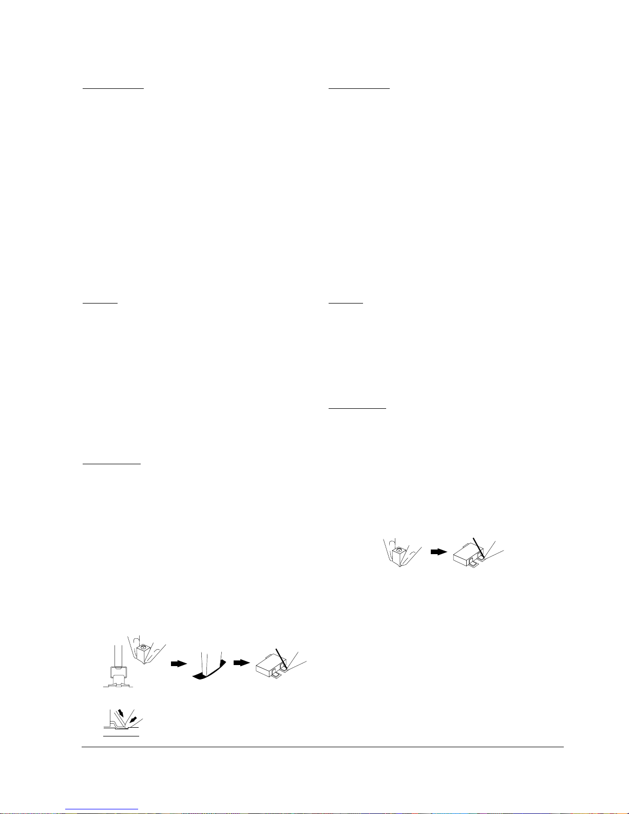
REMOVING
1. Using Two soldering irons:
a. Use thin tip soldering irons
b. Use soldering tip temperature of about 280oC.
c. Simultaneously heat both ends of the part.
d. While heating, grasp the part with the tips of the
soldering irons and remove it.
e. Use desoldering wire to completely remove the
old solder from the part location on the board. A
clean pattern for installing the new part is very
important.
Samsung Electronics 3-3
Reference Information
3-2 Chip Replacement (SMD)
INSTALLING
1. Clean the area where the new part is to be
mounted.
2. Apply a water soluble flux.
3. Set part correctly into position and prevent is from
shifting.
4. Bring the soldering iron tip close to the part contact
without actually touching it. Melt thin (0.3mm)
solder between the tip and part so that it flows into
the part contact.
5. Check work quality with a magnifying lens.
3-2-4 Chip Tantalum Capacitors and
Chip filters
TYPES
The types of chip tantalum capacitors and chip filters
are as follows:
· Chip Inductors
· Chip Tantalum Capacitors
· Chip Tantalum Electrolytic Capacitors
· Chip Aluminum Electrolytic Capacitors
· Chip Transformers
· Chip Filters
REMOVING
1. Using a special desoldering iron:
a. Select soldering tip according to part size.
b. Bring the tip into contact with the solder points.
c. When the solder melts, remove the part.
d. Remove the old solder with desoldering wire.
2. Using a special desoldering iron:
a. Use small flat-blade tips.
b. Heat both ends of the part simultaneously.
c. When the solder melts, grasp and remove the
part with the soldering iron tips.
d. Remove the old solder with desoldering wire.
INSTALLING
1. Clean the area where the new part is to be
mounted.
2. Apply a water soluble flux.
3. Set part correctly into position and prevent it from
shifting.
4. Use a sharp soldering iron tip. Bring the tip close to
the part contact without actually touching it. Melt
thin (0.3mm) solder between the tip and part so
that it flows into the part contact.
5. Check work quality with a magnifying lens.
3-2-5 Chip VRs, Chip Trimmer
Capacitors, Diode and Tr.
TYPES
The types of parts are as follows:
· Chip VRs
· Chip Trimmer Capacitors
· Diode
· Transistors
REMOVING
1. Using two soldering irons.
a. Use small-flat-blade tips.
b. Heat the leads of the part simultaneously.
c. When the solder melts, grasp and remove the
part with the soldering iron tips.
d. Remove the old solder with desoldering wire.
3-4 Samsung Electronics
Reference Information
INSTALLING
1. Clean the area where the new part is to be
mounted.
2. Apply a water soluble flux.
3. Set part correctly into position and prevent is from
shifting.
4. Use a sharp soldering iron tip. Bring close to the
part contact without actually touching it. Melt thin
(0.3mm) solder between the tip and part so that it
flows into the part contact.
3-2-6 Chip ICs
TYPES
The types of chip ICs are as follows:
1. SOP (Small Outline Package) IC
2. SSOP (Shrink Small Outline Package) IC
3. VSOP (Very Small Outline Package) IC
4. QFP (Quad Flat Package) IC
5. VQFP (Very Quad Flat Package) IC
6. PLCC (Plastic Leaded Chip Carrier) IC
7. TSOP (Thin Small Outline Package) IC
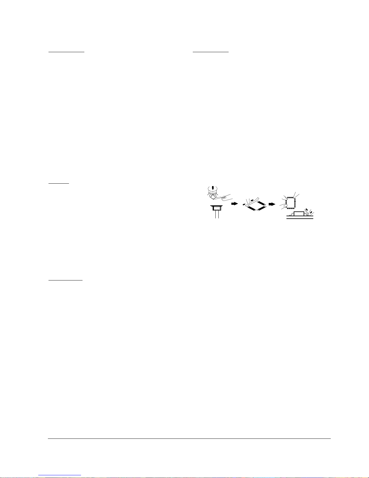
REMOVING
1. Using special desoldering iron:
a. Select the tip according to the size shape of the
IC.
b.“Tin” the tip with a small amount of the IC leads.
c. Set the tip squarely over the IC leads.
d. When the solder melts, carefully twist the iron.
e. Raise and remove the IC.
2. Using a shaped air-blower unit:
a. Select the correct nozzle.
b. Select the temperature and air-blow
(suggested : temperature : 7, air-blow:4)
c. Engage the IC removing tool.
d. Use the air-blow the preheat the IC for about 5
seconds, then heat with the nozzle until the IC
remove lifts the part from the board.
INSTALLING
1. Use desoldering wire to remove the previous solder
2. Clean the location.
3. Apply water soluble flux.
4. Position the IC and solder two pins at opposite
sides.
5. Use a sharp tipped soldering iron and carefully
solder each pin. (After gaining experience, a thicker
tip can be used for better work efficiency)
6. Remove any solder bridges with desoldering wire.
7. Inspect the work with a magnifying lens.
Samsung Electronics 3-5
IC
Reference Information
DIAGNOSTIC CINTROL UNIT
QUICK REFERENCE
Model :ML-6000 Series
DocuPrint P1202
04 BIAS52
05 LSU READY
07 1ST PAPER
08 ENVELOPE
09 COVER OPEN
10 OVER HEAT
BIAS1
LSU MOTOR & LD
SCF PAPER EMPTY
EXIT SENSOR
PRINT HEAT
BIAS0
LSU MOTOR
MP PAPER
FEED SENSOR
STANDBY
OFF
ON
SELF
TEST
00 MAIN MOTOR ON
01 MHV ON
02 THV "-"ON
03 THV "+" REF VOLTAGE
04 BIAS ON
05 LSU ON
06 PICK UP ON
07 CHECK PAPER EMPTY SENSOR
08 CHECK FEED EXIT SENSOR
09 CHECK COVER SENSOR
10 FUSER ON
11 HOT BURNING
12 CLEAN PRINT
13 CHECK THV ON DUTY
14 THERMISTER II CHECK
15 FAN ON
DIAGNOSTIC CODE
00 READY(LEGAL)
01 READY(LETTER)
02 READY(A4)
03 READY(EXECUTIVE)
04 READY(B5)
05 READY(FDLIO)
20 PRINT START
22 PRINT START(2’CASSETTE)
23 PRINT START(MP TRAY)
30 FEED SENSOR 1’st ON
31 FEED SENSOR 1’st OFF
40 FEED SENSOR 2’nd ON
50 PAPER OUT
60 OPEN FUSER ERROR
61 WARM UP
62 LOW HEAT ERROR
64 COVER OPEN ERROR
68 OVER HEAT ERROR
70 NO PAPER or NO CASSETTE
71 PAPER JAM0
72 PAPER JAM1
73 PAPER JAM2
90 MPF PRINT MODE
94 NO PAPER in MP TRAY
95 LSU NOT READY
99 GREEN MODE
STATUS CODE
STATUS
DIAGNOSTIC
DCU MODE DOWN SHIFT STOP
UP
ENTER
IF YOU WANT TO ENTER THE DCU MODE.
TURN THE POWER SWICH ON WHILE PRESSING ALL THREE KEYS.
3-3 Recommended Test Equipment
Samsung recommends the following equipment when servicing the Laser Printer.
Digital Multimeter Adigital multimeter with attached LED or LCD 4-digit Panel
Oscilloscope A digitizing oscilloscope which can measure more than 100MHz
High Voltage Probe A high voltage probe which can measure about less than 10KV
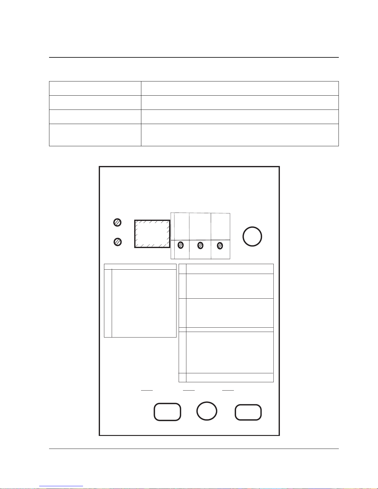
DCU (Diagnostic Control Unit) DCU can be supplied from Samsung which can easily shows the engine’s
error status
3-6 Samsung Electronics
Table 3-4-1 Equipment List
Figure 3-4-1 DCU
Reference Information

3-4 DCU Control
3-4-1 DCU Setup
1) Connect DCU to Controller Board Connector J6 (4 pins) or Engine Board CN2 (4pins).
2) To apply power, simultaneously press and hold down [DOWN], [SHIFT], and [STOP] keys. ‘78’ is displayed.
3) After 2-3 seconds, release the keys. ‘00’ is displayed.
4) Press [UP] or [SHIFT]+[DOWN] keys until the desired code number is displayed in the DCU display.
5) Press [ENTER] to begin operating.
6) Example : Select numbers ‘13’ and ‘14’ to adjust the electrophotography trigger voltage.
7) To end operation, press [SHIFT] and [STOP] keys.
3-4-2 DCU Diagnostic Mode
The DCU is used to diagnose the printer malfunction status.
Display Diagnostic Code Description
00 MAIN MOTOR ON
01 MHV ON
02 THV(-) ON
03 THV(+) REFERENCE ON
04 BIAS ON
05 LSU ON
06 PICK UP ON
07 CHECK PAPPER EMPTY SENSOR
08 CHECK FEED , EXIT SENSOR
09 CHECK COVER SENSOR
10 FUSER ON
11 HOT BURNING
12 CLEANING PRINT
13 CHECK THV ON DUTY
14 THERMISTER II CHECK
15 FAN ON
Samsung Electronics 3-7
Reference Information
3-8 Samsung Electronics
Reference Information
3-4-3 DCU Error Status Code
DCU error code will indicate malfunction area of the machine.
Display Error status
60 OPEN FUSER ERROR
62 LOW HEAT ERROR
68 OVER HEAT ERROR
64 COVER OPEN ERROR
70 NO PAPER or NO CASSETTE
71 PAPER JAM 0
72 PAPER JAM 1
73 PAPER JAM 2
95 LSU NOT READY
3-4-4 Error Solution
Display Solution
60, 62, 68 1. Measure the resistance of the AC connector on the Fuser. Normal resistance is 2-4
ohmsfor 110V, 6-8 ohms for 220V.
2. Check if the fuser lamp works properly.
3. Measure the resistance at Q101 on the engine board. If abnormal, replace Q101, Q3,
PC151, Q8.
70 1. Make sure that paper is loaded in the cassette.
2. Replace OP2 sensor (photo interrapter).
3. Check if the feed clutch works properly.
4. If abnormal, replace the feed clutch or Q4 on the engine board.
71 1. Make sure that paper is loaded in the cassette.
2. Check for pick-up unit. If it is heavily worn, replace it with new one.
3. Replace OP1 sensor.
72, 73 1. Make sure that the paper being used meets the specification.
2. Check if there is a paper jam in the fuser.
3. Replace OP1, OP3 on the engine board.
4. Check the fuser roller for any dirt. If dirty, clean the roller.
95 1. Check for U205 on the engine board.
2. Replace LSU.
3. Measure the resistance at R62 and R8. If abnormal, replace them.

4. Disassembly and Reassembly
4-1 General Precautions on Disassembly
When you disassemble and reassemble components, you must use extreme caution. The close proximity of
cables to moving parts makes proper routing a must. If components are removed, any cables disturbed by the
procedure must be restored as close as possible to their original positions. Before removing any component
from the machine, note the cable routing that will be affected.
Whenever servicing the machine, you must perform as follows:
1. Remove the paper cassette(s), and the print cartridge. Do not expose the cartridge to direct room light or
sun light, and be careful not to scratch the drum surface.
2. Turn the power switch off.
3. Unplug all the cables from the printer.
4. Replace with only an authorized component.
5. Do not force to open or fasten a plastic material component.
6. Be careful no obstacles are included when you reassemble components.
7. When you reassemble components, be careful small size components are located in place.
8. If you turn the machine over to replace some parts, toner or paper particles may contaminate the LSU
window. Protect the LSU window with clean paper.
Releasing Plastic Latches
Samsung Electronics 4-1
Many of the parts are held in place with plastic
latches. The latches break easily; release them
carefully. To remove such parts, press the hook end
of the latch away from the part to which it is latched.
4-2 Samsung Electronics
Disassembly and Reassembly
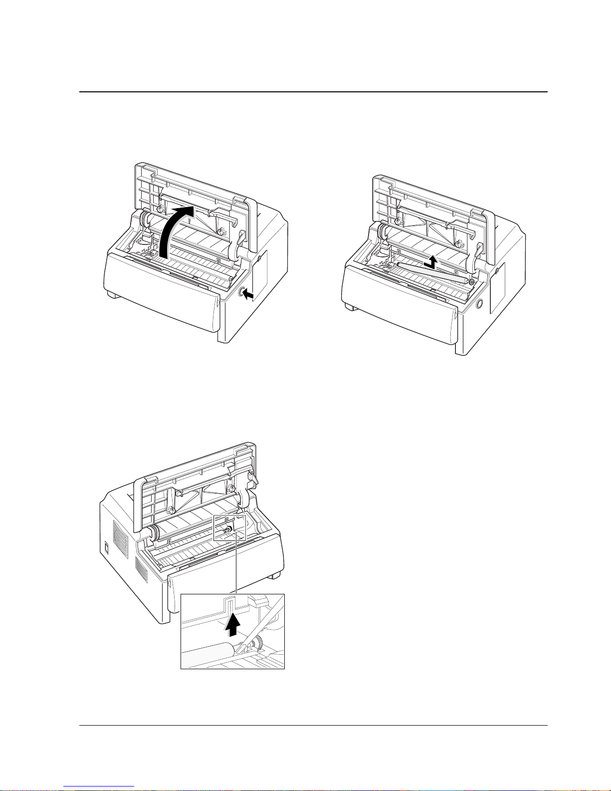
4-2 Transfer Roller
1. Press the cover open switch and raise the
printer cover.
3. Pull the roller slightly to the right to release the
left end of the roller, then take it out.
2. Use a phillips screwdriver to release the right
end of the roller.
4-3
Samsung Electronics
Disassembly and Reassembly
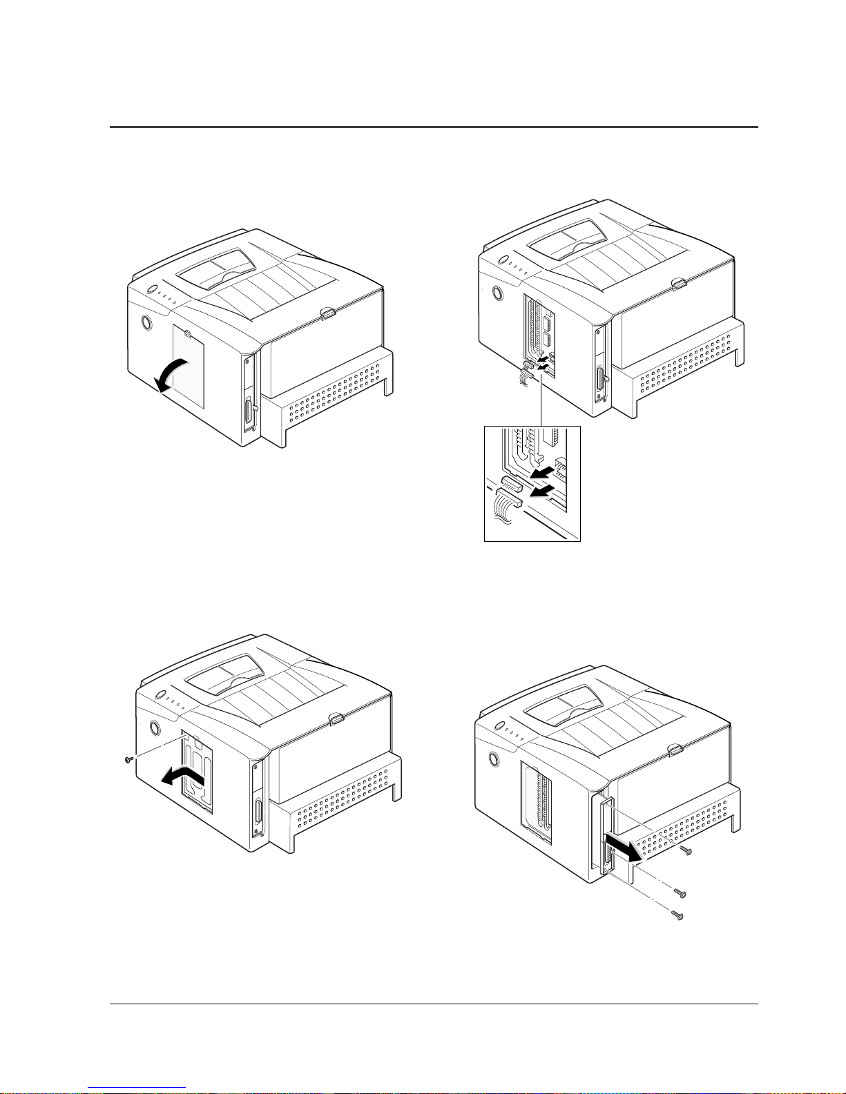
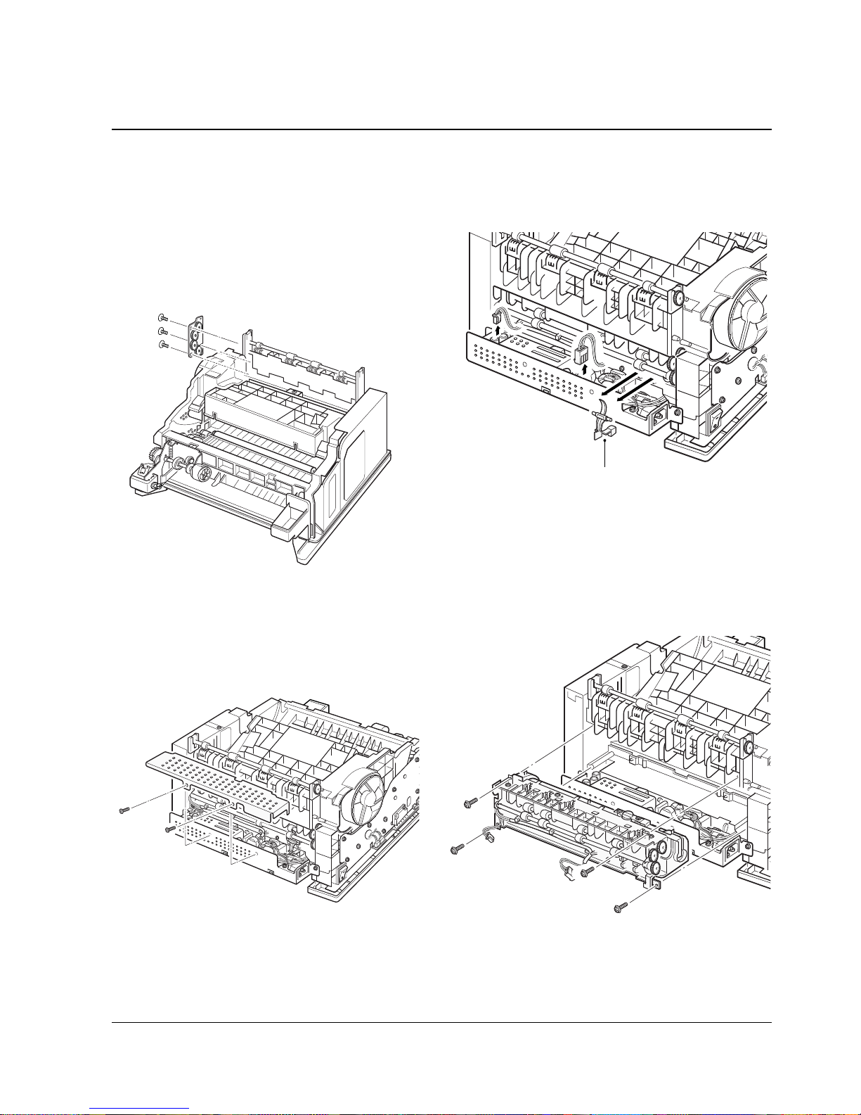
4-3 Controller Board
1. Remove the cover located at the right side of the
printer.
2. Remove one screw. Slide the shield cover in the
direction of OPEN arrow marked on the cover,
then remove the cover.
3. Unplug two connectors from the board.
4. Remove three screws securing the board and
pull the board out of the printer.
4-4 Samsung Electronics
Disassembly and Reassembly
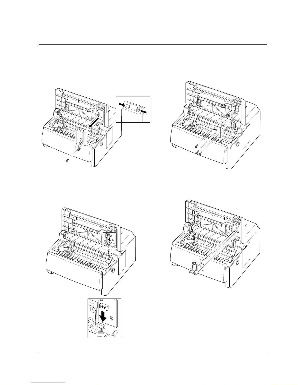
4-4 Panel Board
2 Remove two screws, unlatch the panel cap, then
remove it.
1 Press the cover open switch and raise the
printer cover.
3. Unplug one connector from the panel board.
4 Remove three screws from the board, and
remove the board.
5. Remove the Window LED and button panel LED.
4-5Samsung Electronics
Disassembly and Reassembly
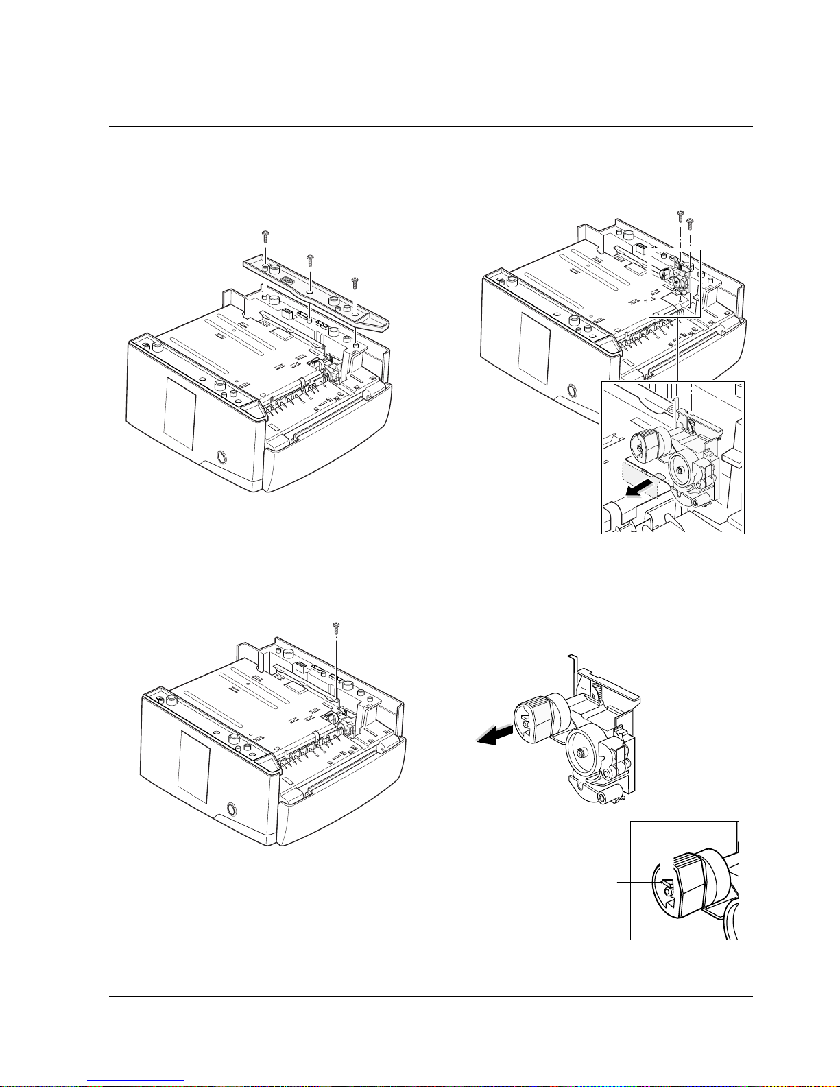
4-5 Pickup Assembly
1. Turn the printer over. Remove three screws
from the left base bracket, and take the bracket
out.
2. Remove one ground screw.
3. Remove two screws securing the pickup
assembly and take the assembly out.
4. Check the pickup rubber wear. If the rubber is
heavily worn, replace it with a new one.
Push the solenoid if you
have difficulty to remove
the pickup assembly.
Squeeze this tab
to remove the
rubber.
4-6 Samsung Electronics
Disassembly and Reassembly
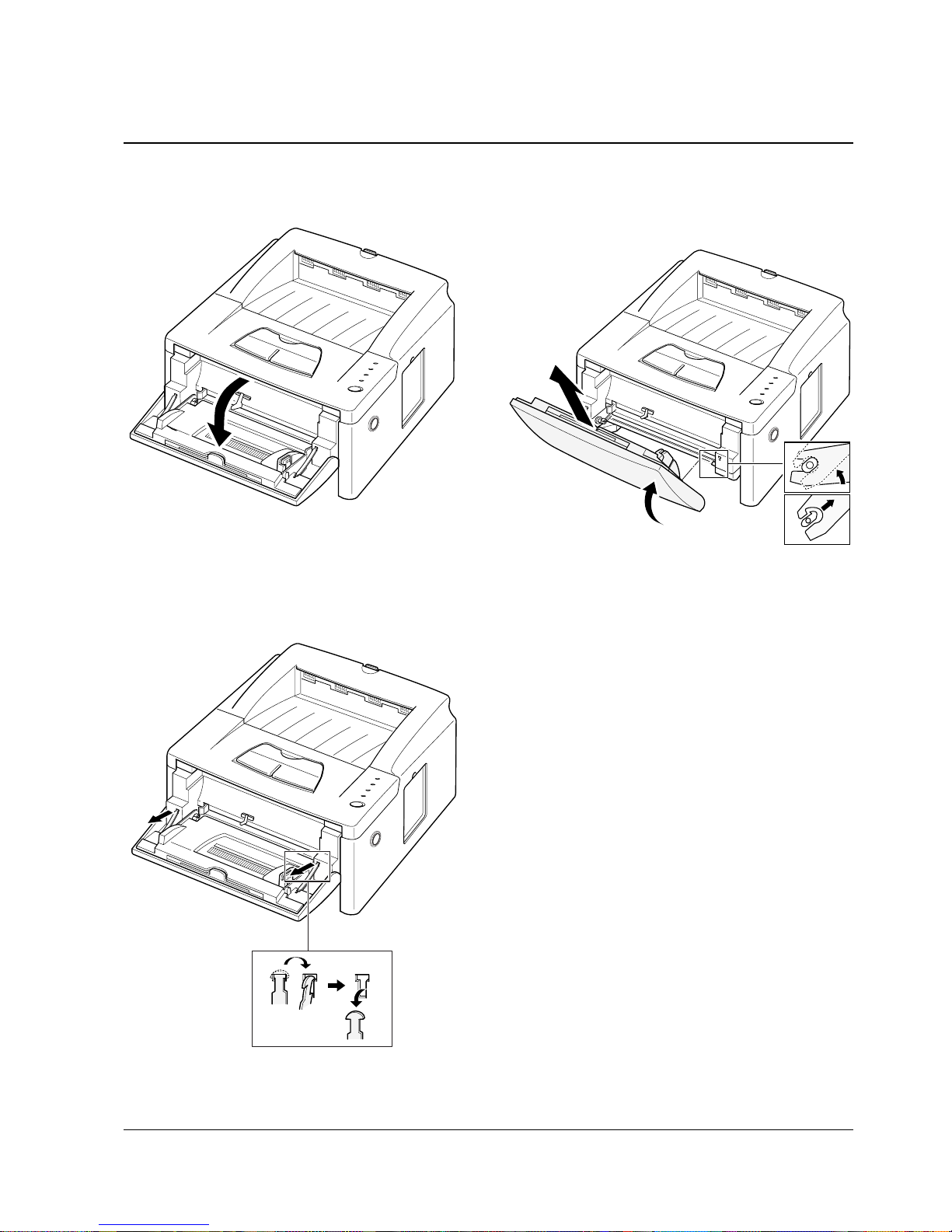
4-6 MP (Multi-Purpose) Tray
1. Open the MP tray.
2. Release two stoppers.
3. Rotate the MP tray upward to a 45Oangle to
unlatch the both ends of the tray, then take it out.
Samsung Electronics 4-7
Disassembly and Reassembly
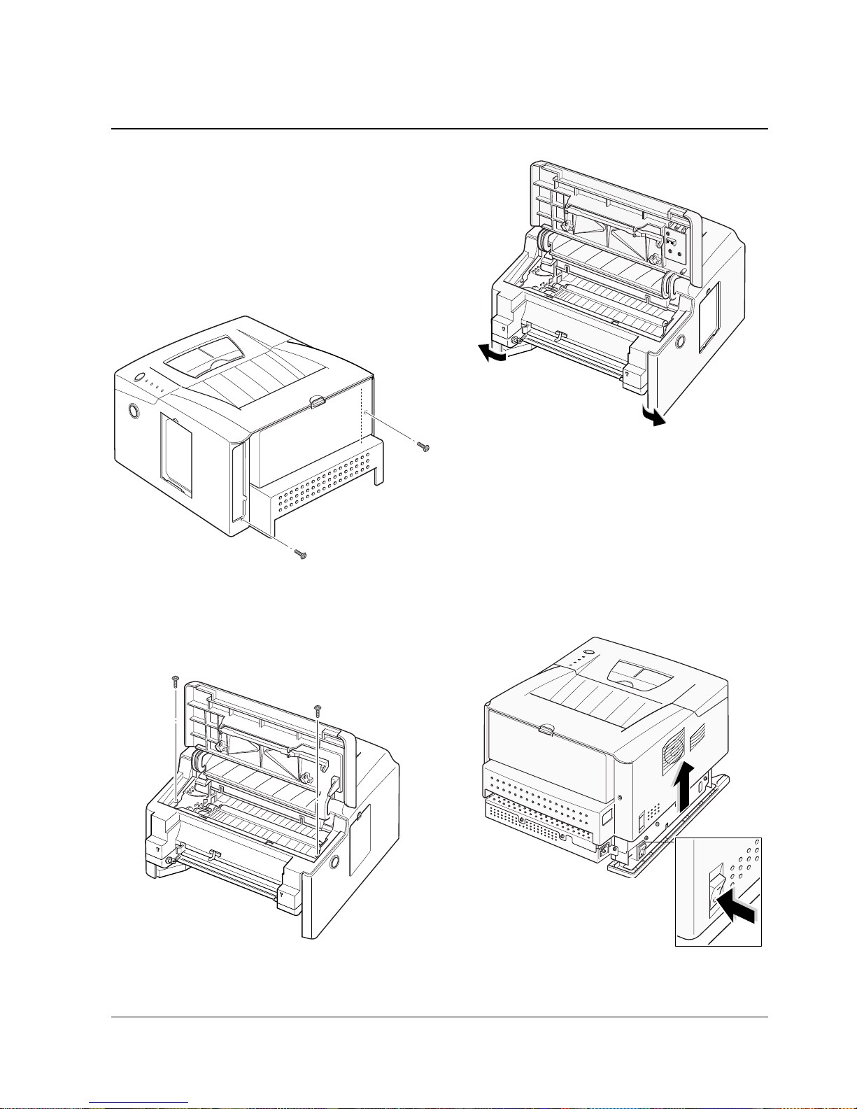
4-7 Main Cover
1. Before you remove the cover, you should
remove:
-Controller Board (see page 4-3)
-Panel Board ( see page 4-4)
-MP Tray (see page4-6)
2. Remove two screws at the back of the printer.
3. Open the printer cover, and remove two screws.
6. Unlatch the front ends of the cover.
Note: When you reassemble the cover, push the empty
actuator in.If not, the cover is not in place.
7. Slide the main cover upward, out of printer.
Note that the power switch is
properly released when you
remove the cover.
4-8 Samsung Electronics
Disassembly and Reassembly
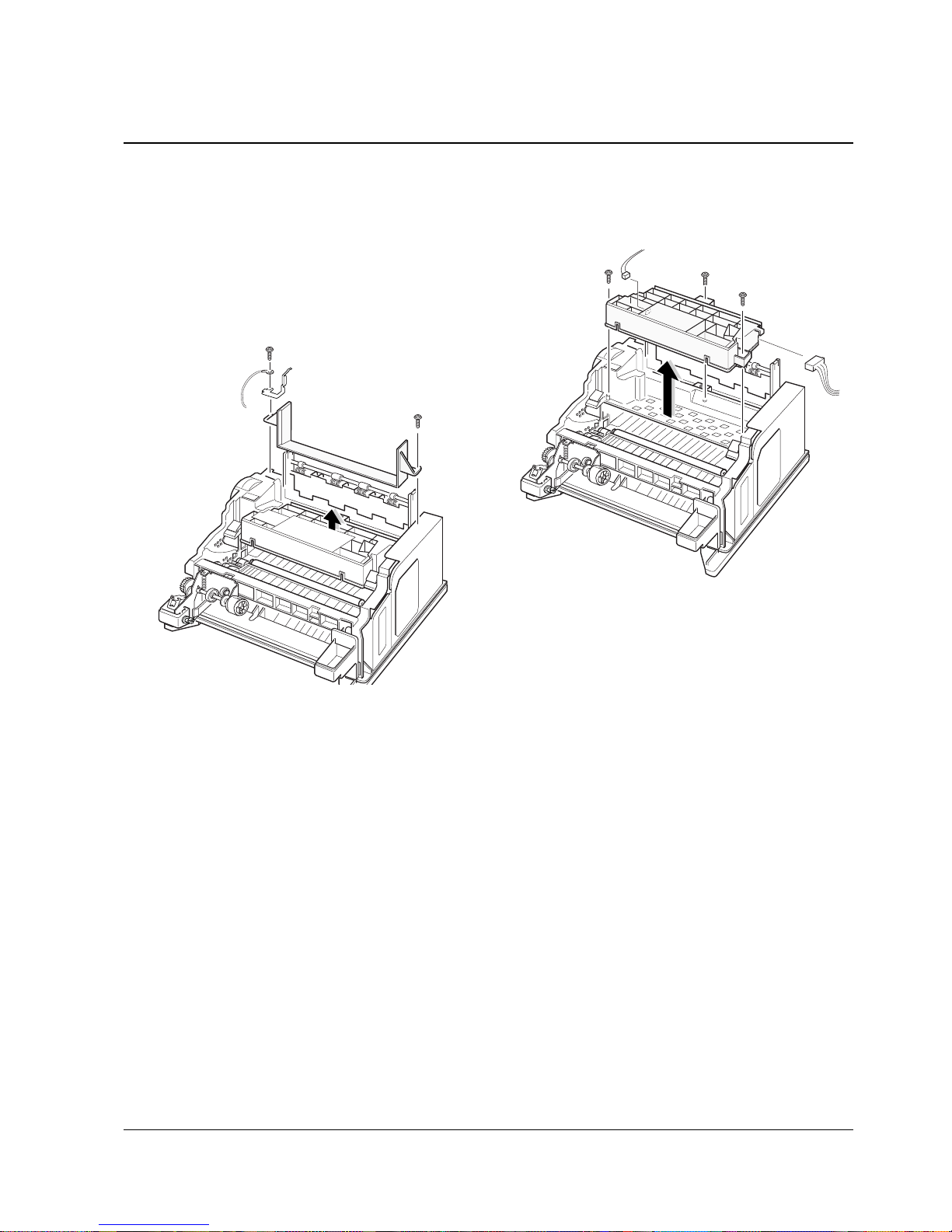
4-8 LSU
1. Before you remove the LSU, you should remove:
-Controller Board (see page 4-3)
-MP Tray (see page xx)
-Main Cover (see page 4-6)
2. Remove two screws securing the fuser cover,
and remove the fuser cover.
3. Remove three screws, and remove the LSU.
Then unplug two connectors from the LSU.
4-9Samsung Electronics
Disassembly and Reassembly
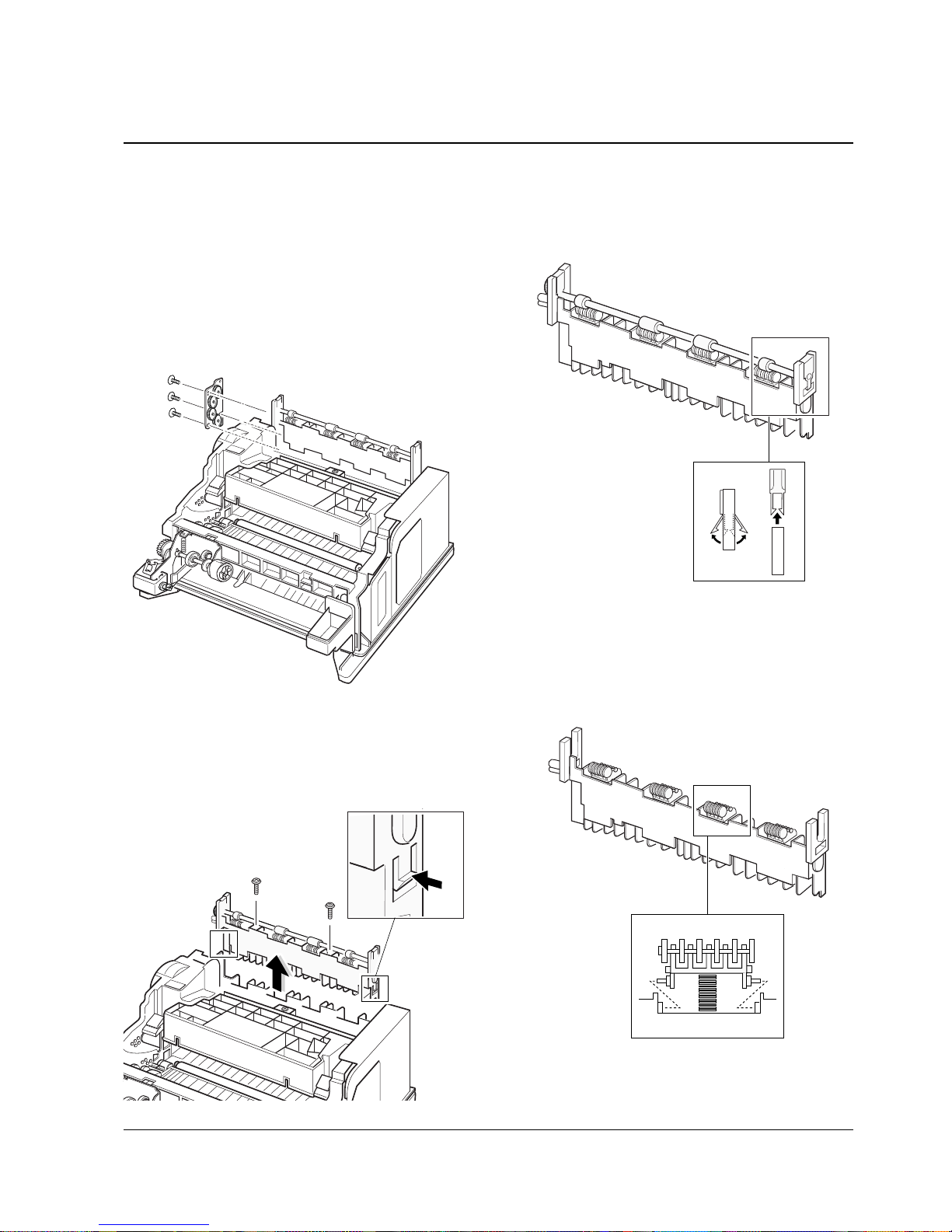
4-9 Exit Assembly
1. Before you remove the exit assembly, you
should remove:
-Controller Board (see page 4-3)
-MP Tray (see page xx)
-Main Cover (see page 4-6)
-Fuser Cover (see page 4-10)
2. Remove three screws, and remove the bracket.
3. Remove two screws, unlatch the exit tray and
take it out.
4. If you want to remove the roller shaft, unlatch
both ends of the shaft and take it out.
5. If you want to remove the exit rollers, sqeeze the
bottom of roller and take it out.
4-10 Samsung Electronics
Disassembly and Reassembly
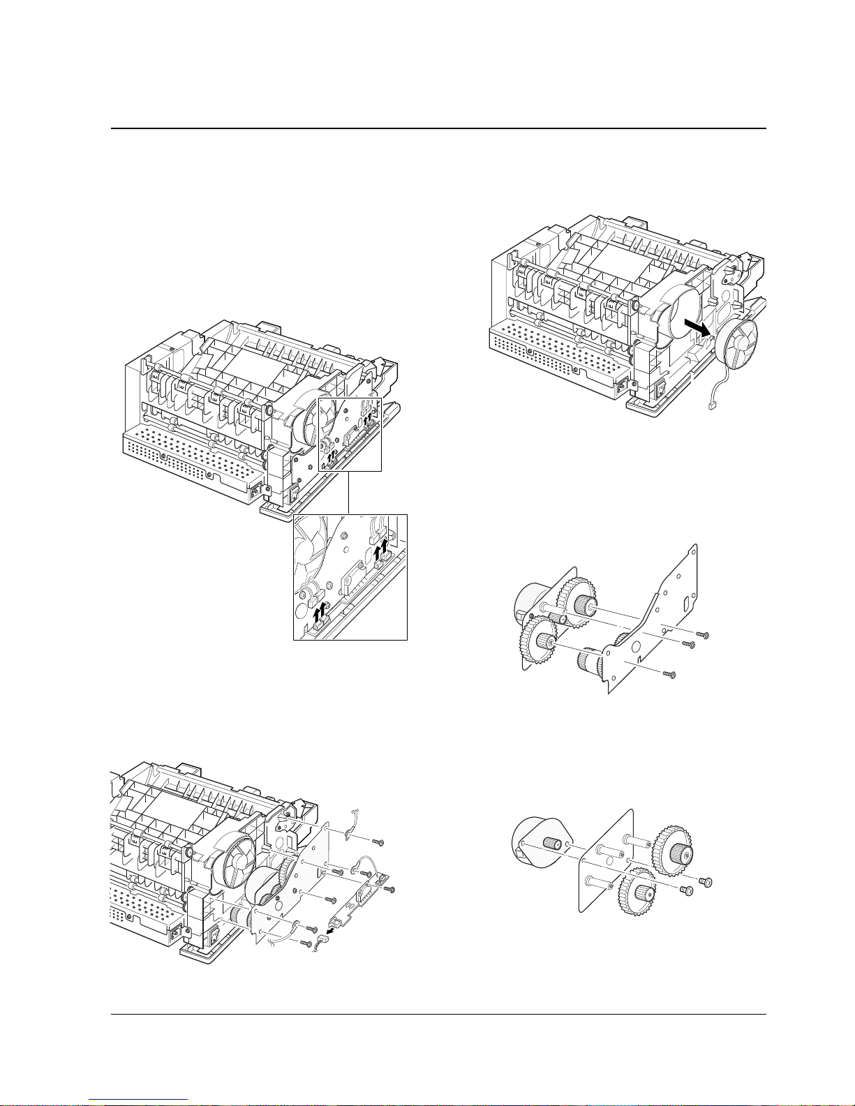
4-10 Drive Assembly and Fan
1. Before you remove the drive assembly or fan,
you should remove:
-Controller Board (see page 4-3)
-Main Cover (see page 4-7)
-MP Tray (see page 4-6)
2. Unplug four connectors.
3. Remove seven screws securing the drive
assembly from the gear bracket, and remove the
drive assembly and motor drive board. Unplug
one connector from the board.
4. If you want to replace the fan, take it out.
5. If you want to remove the motor from the drive
assembly, remove three gold screws securing
the motor assembly to the gear bracket.
6. Remove the motor assembly. Remove two
screws securing the motor to the motor bracket,
then take the motor out.
4-11Samsung Electronics
Disassembly and Reassembly
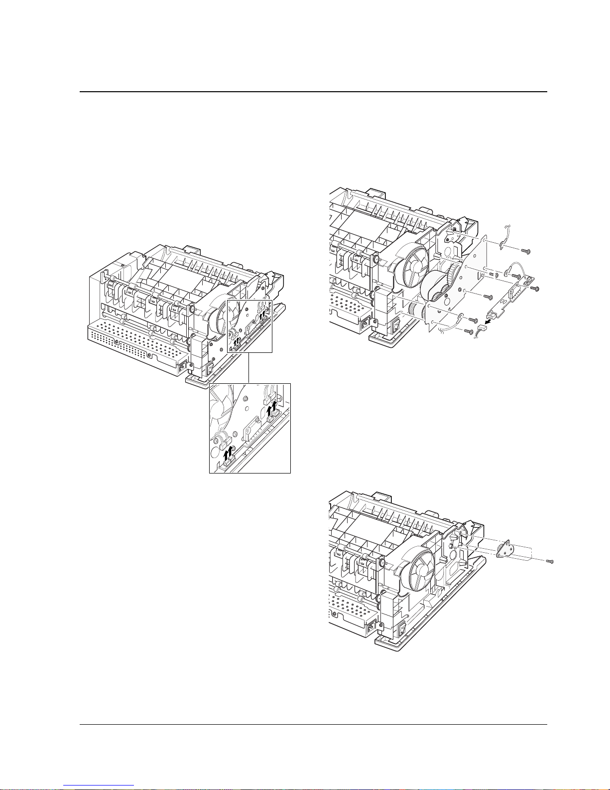
4-11 MP Plate Assembly
1. Before you remove the MP plate assembly, you
should remove:
-Controller Board (see page 4-3)
-Main Cover (see page 4-7)
-MP Tray (see page 4-6)
2. Unplug four connectors.
3. Remove seven screws securing the drive
assembly from the gear bracket, and remove the
drive assembly and motor drive board. Unplug
one connector from the board.
4. Remove three screws, and remove the MP plate
assembly.
4-12 Samsung Electronics
Disassembly and Reassembly
4-12 Fuser
1. Before you remove the fuser, you should
remove:
-Controller Board (see page 4-3)
-Main Cover (see page 4-7)
-MP Tray (see page 4-6)
2. Remove three screws, and remove the bracket.
3. Remove two screws from the SMPS bracket.
4. Remove the exit actuator. Unplug two
connectors.
5. Remove four screws, and remove the fuser
assembly.
Exit Actuator
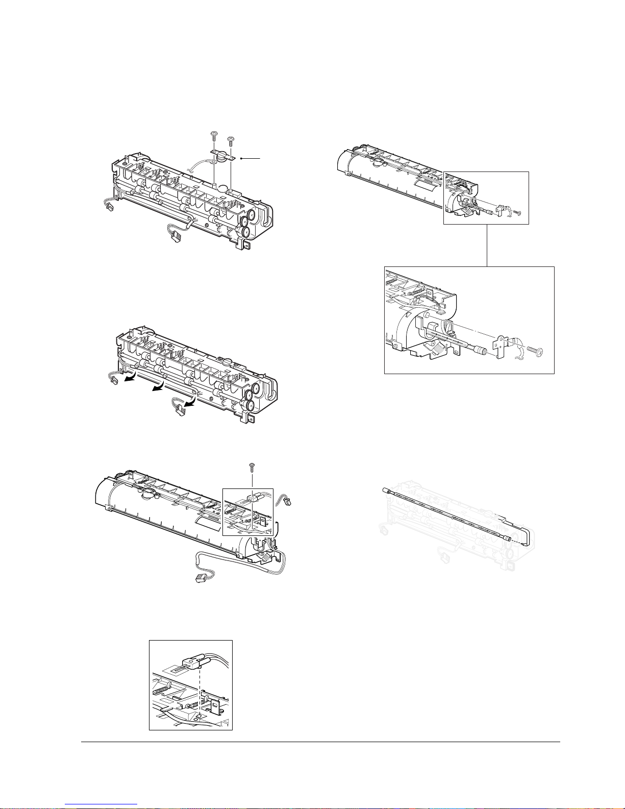
Samsung Electronics 4-13
Disassembly and Reassembly
To remove the thermostat from the fuser
assembly :
Remove two screws, and take the thermostat out.
To remove the halogen lamp from the fuser
assembly :
Remove one screw.
To remove the thermistor from the fuser
assembly :
1. Release the wire from the three holders.
2. Remove one screw, then take the thermistor out.
Note: When you reassemble the thermistor,
make sure that it puts in place.
Note: When you reassemble the halogen lamp,
make sure that it is inserted into the slot
properly.
Thermostat

4-14 Samsung Electronics
Disassembly and Reassembly
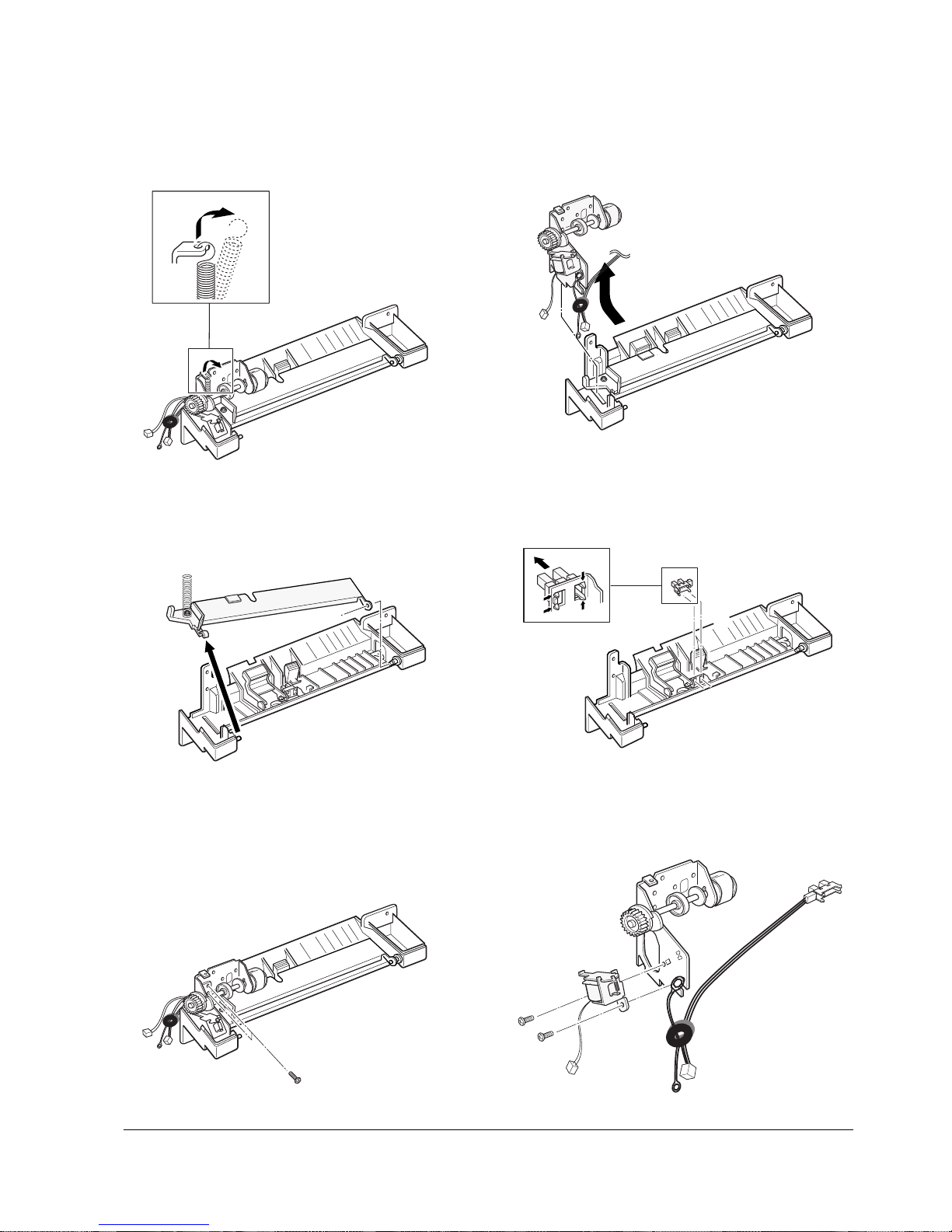
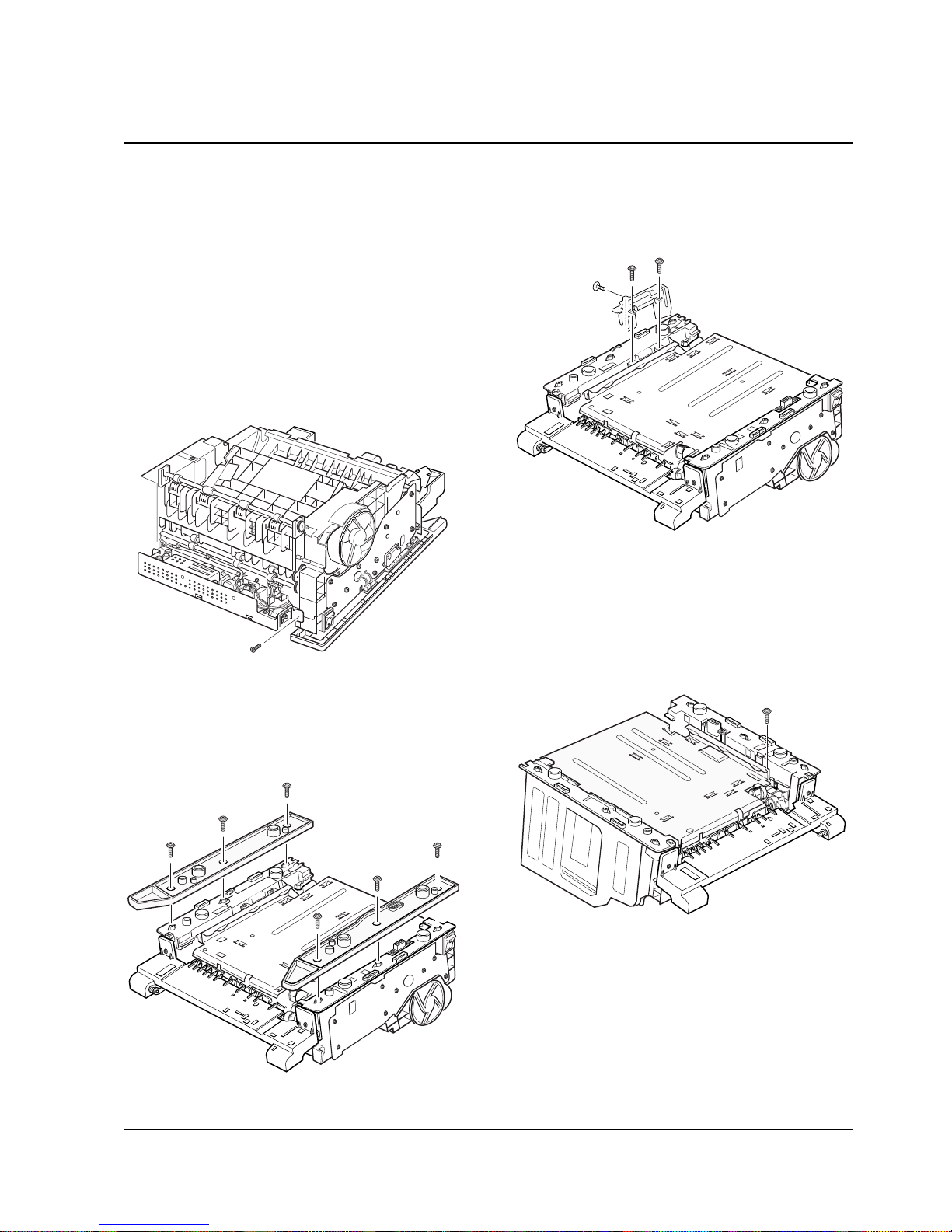
4-13 MPF Assembly and Miscellaneous on MPF Assembly
1. Before you remove the MPF assembly, you
should remove:
-Controller Board (see page 4-3)
-Main Cover (see page 4-7)
-MP Tray (see page 4-6)
2. Unplug two connectors from the drive board.
3. Remove five screws, then remove the MPF
assembly.
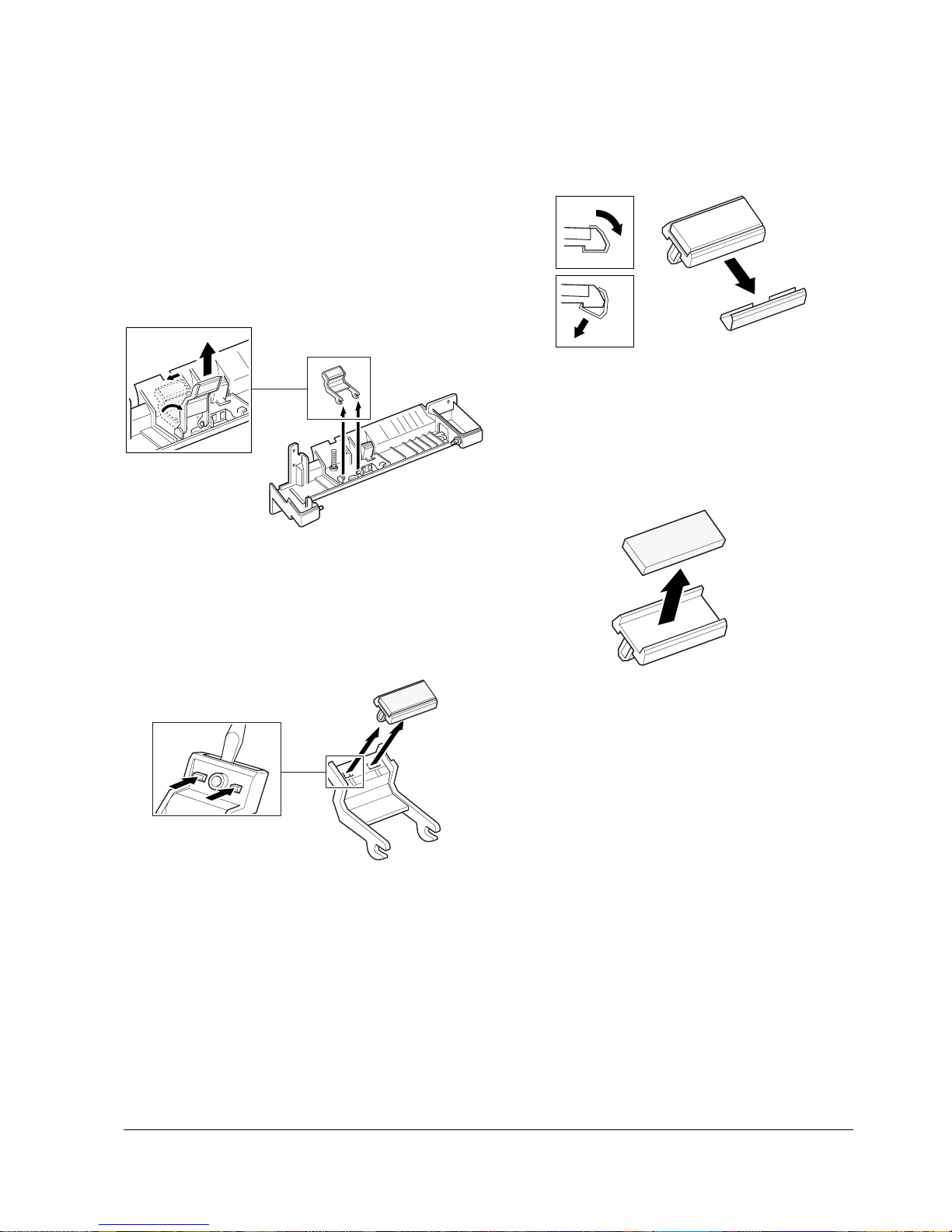
4. To replace the pickup roller on the MPF
assembly:
Squeeze the snap fit on the roller and remove
the roller.
To replace the damper gear on the MPF
assembly :
1) Remove one screw, then remove the damp gear.
Snap fit
4-15Samsung Electronics
Disassembly and Reassembly
4) Pull the MPF bracket out in the direction of arrow.
2) Rotate the right end of the knockup plate until it
is released, then take it out.
5) Unlatch the PE sensor, then take it out.
To replace the solenoid on the MPF assembly :
1) Remove the spring.
3) Remove two screws.
6) Remove two screws from the MP bracket, then
remove the solenoid.
4-16 Samsung Electronics
Disassembly and Reassembly
To replace the pickup holder on the MPF assembly :
1) Before you remove the pickup holder, you shoud
remove the MP bracket (see page xx) and PE sensor
(see page xx) on the MPF assembly.
2) Pull the pickup holder to the left and rotate it until the
both ends of the holder are properly released, then
pull it up.
4) Remove the pickup guide.
3) Remove the pickup pad using a proper tool.
5) Remove the holder pad.
4-17Samsung Electronics
Disassembly and Reassembly
4-14 Engine Board and Miscellaneous
1. Before you remove the engine board, you should
remove:
-Controller Board (see page 4-3)
-Main Cover (see page 4-7)
-MP Tray (see page 4-6)
2. Remove the SMPS bracket as described in ‘4-10
Fuser’ and unplug four connectors.
3. Remove one screw from the engine board.
5. Remove three screws securing the ICU ground,
and remove the ICU ground.
4. Turn the printer over. Remove six screws from
the left and the right base brackets, and take
them out.
6. Remove one ground screw.
 Loading...