

Page 1
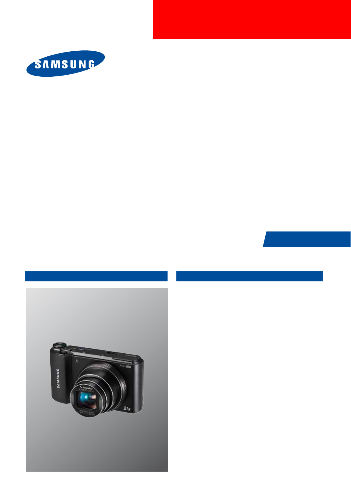
DIGITAL CAMERA
WB850F/WB855F
SERVICE
DIGITAL CAMERA
Manual
CONTENTS
1. Repair information
2. Product specifications
3. Disassembly and Reassembly
4. PCB diagram
5. Block diagram
6. Firmware update
7. Adjustment
8. Exploded view and parts list
Page 2

Contents
1. Repair information
1-1 Customer satisfaction statement ............................................. 1-1
1-2 Warranty and repair service information .................................. 1-1
1-3 Precaution for disassembly and reassembly ............................ 1-4
2. Product specifications
2-1 Specifications ........................................................................ 2-1
2-2 Product comparison ............................................................... 2-2
2-3 Accessories information .......................................................... 2-3
2-4 About the memory card ........................................................... 2-5
2-5 About the battery .................................................................... 2-6
3. Disassembly and Reassembly
3-1 Screw parts list ...................................................................... 3-1
3-2 Camera Disassembly .............................................................. 3-2
3-3 Barrel Disassembly .............................................................. 3-12
3-4 Barrel Reassembly ............................................................... 3-18
4. PCB diagram
4-1 MAIN PCB ............................................................................. 4-1
4-2 STROBE PCB ........................................................................ 4-2
4-3 TOP FPCB ............................................................................. 4-2
4-4 GPS PCB ............................................................................... 4-3
5. Block diagram
5-1 Block diagram ....................................................................... 5-1
Page 3

Contents
6. Firmware update
6-1 Product reset .......................................................................... 6-1
6-2 Version check ......................................................................... 6-3
6-3 Upgrade ................................................................................. 6-4
6-4 How to update the fimware when forced to quit ....................... 6-6
7. Adjustment
7-1 Basic guide for adjustment ...................................................... 7-1
7-2 Lens shading .......................................................................... 7-3
7-3 Shutter close time ADJ ........................................................... 7-4
7-4 IRIS ADJ ................................................................................ 7-5
7-5 CMOS gain ADJ ..................................................................... 7-6
7-6 Flash & AWB ADJ ................................................................... 7-7
7-7 Punt ADJ ................................................................................ 7-8
7-8 CMOS defect ADJ ................................................................. 7-10
7-9 OIS centering ADJ ................................................................ 7-10
7-10 Serial number writing process ..............................................7-11
8. Exploded view and parts list
8-1 BODY ASSEMBLY .................................................................. 8-1
8-2 MAIN ASSEMBLY ................................................................... 8-2
8-3 MAIN SUB ASSEMBLY ........................................................... 8-4
8-4 CHAMBER ASSEMBLY ........................................................... 8-6
8-5 TOP COVER ASSSEMBLY ...................................................... 8-7
8-6 FRONT COVER ASSEMBLY .................................................... 8-9
8-7 BACK COVER ASSEMBLY .................................................... 8-10
8-8 BARREL ASSEMBLY .............................................................8-11
8-9 PACKING ITEMS .................................................................. 8-14
Page 4

1. Repair information
1-1 Customer satisfaction statement
We hold ourselves to the highest standards of customer satisfaction and service.
Precautions
■
■
■
■
■
Combining perfect technical solutions with a customer-oriented approach is our top priority.
We treat our customers we serve with kindness, loyalty, respect and dignity.
We are committed to earn customers’ trust continuously through excellence in repair solutions.
We keep our promises and commitments to our customers.
Committed to quick and easy resolution of all support issues, we deliver industry-leading
response times.
[Guide]
We listen carefully to our customers' requirements and always nd an optimum solution for their needs.
We are committed to your satisfaction and have procedures in place to provide you with a fair, timely and effective means to resolve problems. It
combines industry leading preventive assistance with responsive support that helps us address problems quickly and effectively.
We will continuously maintain and improve our services to satisfy the needs of our customers.
1-2 Warranty and repair service information
(1) General terms and conditions
It is guaranteed to be free of charge from defects in material and workmanship under normal use for a period
of one year from date of purchase.
Digital Camera and lens come with a one year limited warranty from the date of purchase.
* The duration of the warranty depends on the laws in the country in which it was purchased.
The following information will be required to process warranty requests:
a. We imply warranties to one year from the original date of purchase. In the event that the purchaser is
unable to provide a warranty card or proof of purchase, the warranty period will be determined by the
date of manufacture. The warranty period shall be decreased to three months from the original product
manufactured date.
b. The coverage under this warranty begins on the date of your purchase of the product. In the event
that a warranty card or proof of purchase is not available, a purchase receipt, preferably the purchase
invoice, to conrm the date of purchase is required for warranty service.
c. In the event that a valid date of purchase is not available, the warranty period will be determined by
the date of manufacture. The warranty period shall be decreased to three months from the original
product manufactured date.
Copyright© 1995-2012 SAMSUNG. All rights reserved.
1-1
Page 5
Precautions
(2) Limited Warranty
It reserves the right to retain any parts or components replaced at its discretion in the event of a defect noticed in the product. The period with respect to retaining components may vary respectively depending on its
components. We are not liable to repair or replace its faulty product after the Warranty Period has expired.
* We warrant its retaining camera and lenses for ve years and three years for the accessories.
a. If a warranty claim is led after the product has been discontinued, we reserves the right to honor the
components warranty. Warranty period may vary depending on the type of components.
b. In the event that no identical warranty information is available for service repair, company has the right to provide warranty.
The warranty does not affect the consumers' rights against the company related to its information.
For the length of the period indicated on the chart below, it starts with the date of original purchase.
(3) Warranty Period for components
Our liability under this warranty shall be limited to the following:
a. In the event of a same malfunction problem within two months after repair service by Samsung authorized technician,
we will repair or replace free of charge the component of the product which is found to be defective.
b. In the event of the component that you have paid the replacement cost is returned under normal use within one year at our premises,
such components will be replaced free of charge component of the product which is found to be defective.
<Table 1-1 Warranty Periods for Parts>
Part Name Warranty Period
Battery Charger
AC Adaptor
Battery
Remote Control
CD Software
Earphone
Pouch for camera
Cable
Six months
Three months
Not applicable
1-2
Copyright© 1995-2012 SAMSUNG. All rights reserved.
Page 6
(4) Repair Claims
1) Repair free of charge
Essentially, the following causes of damage are covered:
a. Failing to function properly under normal use during the limited warranty period.
b. Repair Services free of charge is granted for the performance of a specic contract.
2) Repair charges
This warranty does not cover damage caused by:
a. Defect occurring after the expiration of the Warranty Period.
b. Damage due to negligence, immersion in water, impact, loss and tampering.
c. Repair or alteration performed by any party other than Samsung authorized technicians.
d. Misuse or other improper use of the power button.
e. Exhausted parts such as batteries, lamps and lters, etc.
f. Defect that occurs due to sand, dirt liquid, etc. entering the inside of the product casing.
Precautions
g. Consumable parts which have ceased working through normal use such as as earphone, battery discharger and various accessories.
h. Products purchased second hand or any damage that occurs due to a second hand or repair performed
by anyone other than Samsung or a Samsung authorized service station.
i. Fire, earthquake, ood or other natural disasters.
The warranty cover period for components is listed below as per table 1-2.
<Table 1-2 Warranty Period for components>
Types of consumer damages Compensation
Required for essential repair within 10 days
after the purchase
Required for essential repair within one
month after the purchase
Failing to perform or
failing to function properly
under normal use
Applicable
to repair
Problem occurred twice
due to same malfunction
Problem occurred three
times due to same
malfunction
Problem occurred four
times due to some other
malfunction
Replace the prod-
uct or refund
Replace the
product or repair
at free of charge
Replace the prod-
uct or refund
-
Repair charges
Free of charge
Repair charges
Not applicable
to repair
Failing to perform or
failing to function properly
as a result of willful intent
and negligence of
customer
Copyright© 1995-2012 SAMSUNG. All rights reserved.
Not applicable to repair
(Except for defects or malfunction as a result
of re or ood or other natural disasters
Within the period with
respect to retaining
components
Applicable repair Repair charges
Replacement
charge
Replace the product at the cost of the
depreciated value or refund its price
added 10% of depreciation
Repair charge and replace the product at the cost of the depreciated value
1-3
Page 7
Precautions
1-3 Precaution for disassembly and reassembly
!
CAUTION
1. Use the anti-static handing procedures included with the anti-static mat to ensure that there is no electrostatic
discharge and component damage.
2. Static electricity is the biggest danger to the PCB parts you are about to disassemble or assemble. It’s important
to use your anti-static wrist strap to prevent damage to these components.
3. Dismantling a discrete electronic component such as main capacitor is dangerous.
The capacitor contains high voltage, which can cause a severe electric shock if you touch it. This holds a
charge even when the unit is not plugged in and is capable of delivering a fatal shock.
4. Using excessive force during disassembly and assembly can damage locking parts. Use care when handling
“Locking parts” to avoid damage to FPCB or wire. Apply pressure only at the points designated in the maintenance
instructions.
5. Due to increasing environmental concerns, a number of restrictions have been placed on the material content
of electronic components and electronic assemblies. It requires utilizing Lead-Free (Pb-free) Soldering.
6. The following precautions must be observed when handling such components below.
<Table 1-3>
Component Precautions
FPCB
CCD (CMOS)
IR CUT Filter
LCD, LENS
PCB Use an anti-static mat as well as an anti-static wrist strap to avoid ESD damage to PCB.
CONNECTOR
FPCB is brittle material. It can be easily damaged thus it should be handled with care.
It is recommended to use wooden or plastic tweezers for manual placement.
Be careful not to stained your nger. It is recommended to use wooden or plastic tweezers
for manual placement. Stain is often caused by the Alcohol used in these components.
Find a clean, well-ventilated place to do your work.
The use wooden or plastic tweezers is recommended for manual placement.
Metal tip tweezer might make marks or damage.
BARREL Always follow proper direction while assembling the components of the barrel.
1-4
Copyright© 1995-2012 SAMSUNG. All rights reserved.
Page 8
2. Product specifications
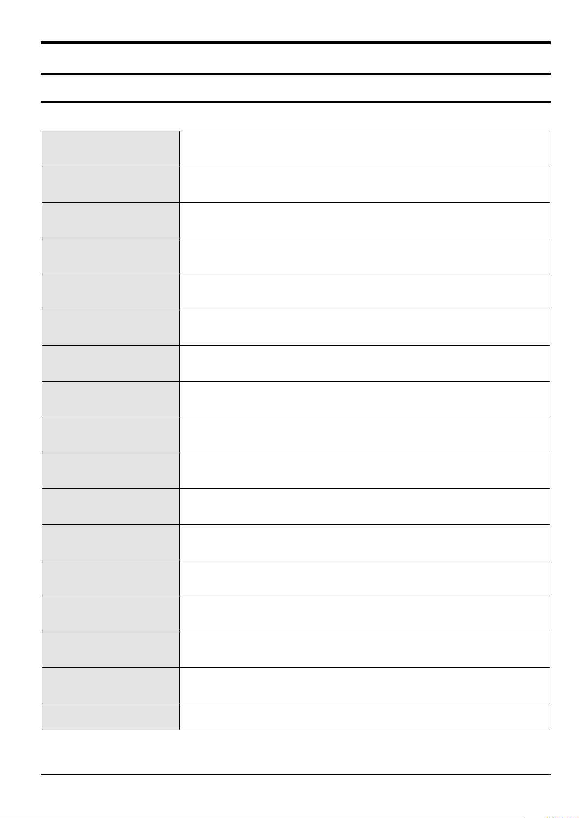
2-1 Specifications
Image Sensor 1/2.3” (Approximately 7.77 mm) BSI CMOS
Effective Pixels Approximately 16.2 mega-pixels
Total Pixels Approximately 16.8 mega-pixels
Wight 232g (without battery and memory card)
Product specications
Dimensions(W X H X D)
Display AMOLED, 3.0” (7.62 cm) 614K
Focal Length Schneider-KREUZNACH 21x Zoom Lens f = 4.1-86.1 mm (35 mm lm equivalent: 23-483 mm)
F-stop Range F2.8 (W)-F5.9 (T)
Digital Zoom Still image mode: 1.0-4.0X (Smart Zoom: 1.33X)
Shutter Speeds
Flash Range
ISO Range Auto, ISO 100, ISO 200, ISO 400, ISO 800, ISO 1600, ISO 3200
Storage
109.5 X 62.2 X 24.9(35.1) mm (without protrusions)
Auto: 1/8-1/2,000 sec. Program: 1-1/2,000 sec.
Night: 8-1/2,000 sec. Manual: 16-1/2,000 sec.
Wide: 0.3-4.96 m (ISO Auto)
Tele: 0.5-2.35 m (ISO Auto)
External memory (Optional):
SD card (up to 2 guaranteed), SDHC card (up to 32 GB guaranteed), SDXC card (up to 64 GB guaranteed)
Shake Reduction DUAL IS [Optical Image Stabilization (OIS) + Digital Image Stabilization (DIS)]
Power Source Lithium-ion battery (SLB-10A, 1030 mAh)
Connector Type Micro USB (7 pin)
Wireless Network
Copyright© 1995-2012 SAMSUNG. All rights reserved.
Social Sharing, Email, MobileLink, Remote Viewnder, Cloud, Auto Backup, TV Link,
Log-in Browser, Wi-Fi Direct
2-1
Page 9
Product specications
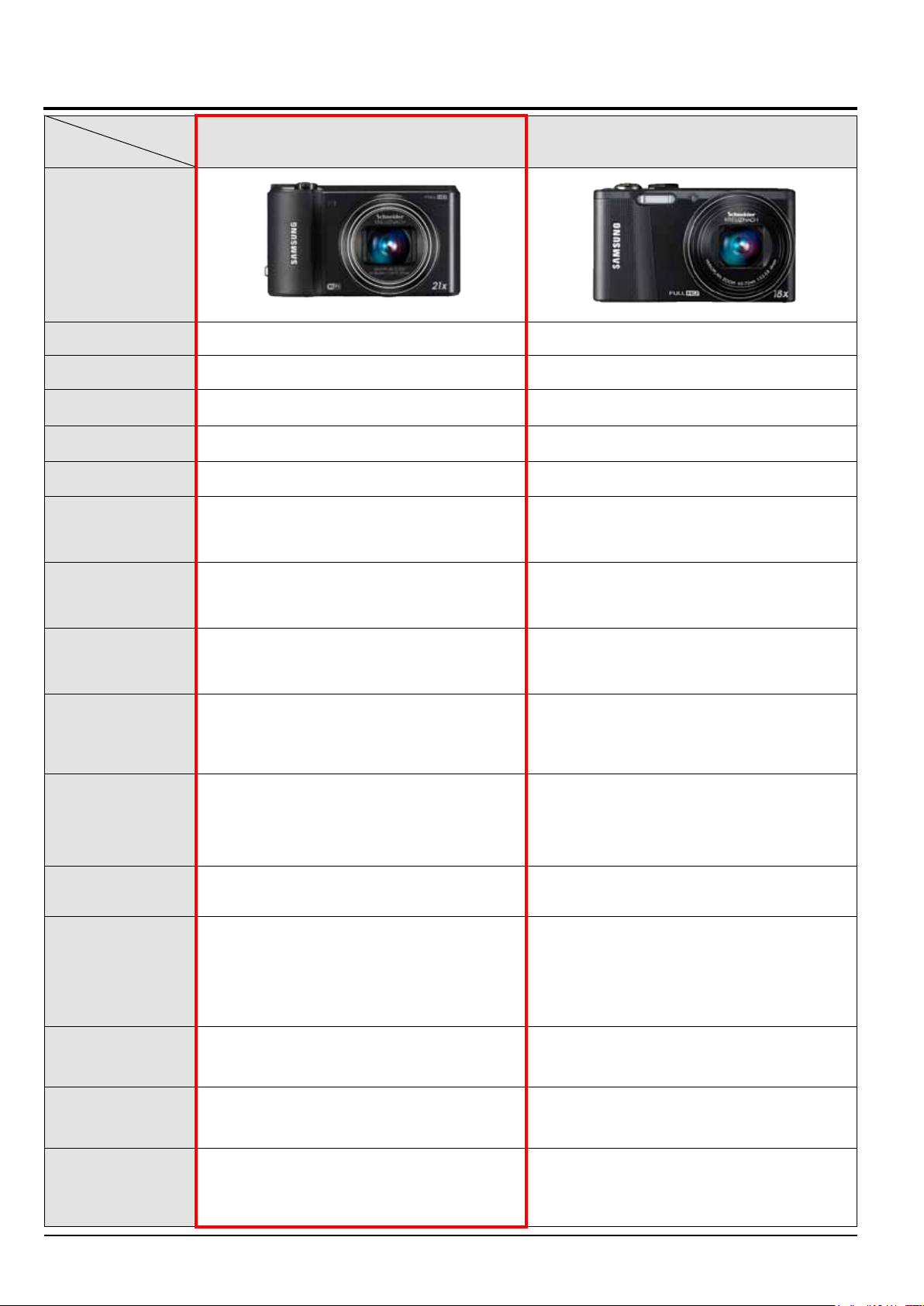
2-2 Product comparison
Model
Specications
Product Image
Image Sensor 1/2.3” (Approximately 7.77 mm) BSI CMOS 1/2.3” (Approx. 7.76mm) BSI CMOS
Effective Pixels Approximately 16.2 mega-pixels Approx. 12.5 mega-pixels
Total Pixels Approximately 16.8 mega-pixels Approx. 14.6 mega-pixels
Wight 232g (without battery and memory card) 193.4g (6.822 oz.) (without battery and memory card)
Dimensions(W X H X D)
Display AMOLED, 3.0” (7.62 cm) 614K TFT LCD, 3.0” (7.62 cm) hVGA
Focal Length
109.5 X 62.2 X 24.9(35.1) mm (without protrusions) 105.3 X 59.4 X 24.9 mm (without protrusions)
Schneider-KREUZNACH 21
x Zoom Lens f = 4.1-86.1 mm
(35 mm lm equivalent: 23-483 mm)
WB850F/WB855F WB750
Schneider-KREUZNACH Lens f = 4.0-72.0 mm
(35 mm lm equivalent: 24-432 mm)
F-stop Range F2.8 (W)-F5.9 (T) F3.2 (W)-F5.8 (T)
Still image mode: 1.0-18.0X
(Optical zoom X Digital zoom: 72.0X,
Smart zoom X Digital zoom: 72.0X)
Auto: 1/8-1/2,000 sec. Program: 1-1/2,000 sec.
Night: 8-1/2,000 sec. Manual: 16-1/2,000 sec.
Auto, ISO 100, ISO 200, ISO 400, ISO 800, ISO 1600,
ISO 3200
Internal memory: Approximately 8.3 MB
External memory (Optional):
- SD card (1-2 GB guaranteed)
- SDHC card (up to 32 GB guaranteed)
- SDXC card (up to 64 GB guaranteed)
DUAL IS [Optical Image Stabilization (OIS) +
Digital Image Stabilization (DIS)]
Digital Zoom
Shutter Speeds
ISO Range
Storage
Shake Reduction
Still image mode: 1.0-4.0X
(Smart Zoom: 1.33X)
Auto: 1/8-1/2,000 sec. Program: 1-1/2,000 sec.
Night: 8-1/2,000 sec. Manual: 16-1/2,000 sec.
Auto, ISO 100, ISO 200, ISO 400, ISO 800, ISO 1600,
ISO 3200
External memory (Optional):
- SD card (up to 2 guaranteed)
- SDHC card (up to 32 GB guaranteed)
- SDXC card (up to 64 GB guaranteed)
DUAL IS [Optical Image Stabilization (OIS) +
Digital Image Stabilization (DIS)]
Power Source Lithium-ion battery (SLB-10A, 1030 mAh) Lithium-ion battery (SLB-10A, 1050 mAh)
Social Sharing, Email, MobileLink, Remote Viewnder,
Wireless Network
2-2
Cloud, Auto Backup, TV Link, Log-in Browser,
Wi-Fi Direct
Copyright© 1995-2012 SAMSUNG. All rights reserved.
-
Page 10
Product specications
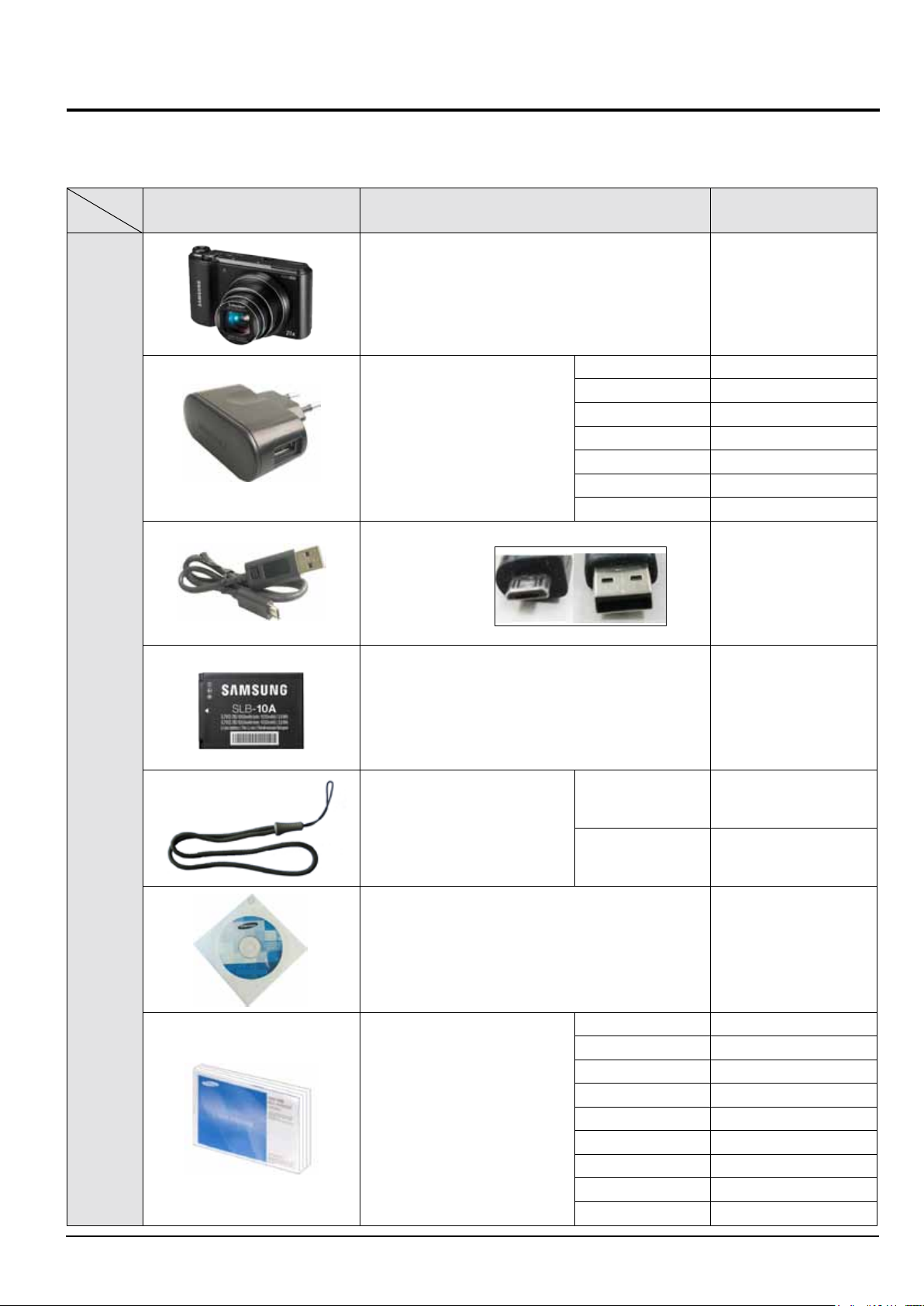
2-3 Accessories information
• The illustrations may differ slightly from the items shipped with your product.
• You can purchase optional accessories at a retailer or a Samsung service center. Samsung is not responsible for any problems caused
by using unauthorized accessories.
Image Description Parts No.
Camera WB850F/WB855F
AD5055_EXP AD44-00183A
AD5055_USA AD44-00179A
AD5055_UK AD44-00182A
AC adapter
USB cable AD39-00190A
AD5055_AUS AD44-00185A
AD5055_ARG AD44-00181A
AD5055_BRA AD44-00180A
AD5055_CHI AD44-00184A
Packing
items
WB850F/WB855F
Battery 4302-001221
Strap
User Manual CD-ROM (WB850F) AD46-00434A
Quick Start Guide
Copyright© 1995-2012 SAMSUNG. All rights reserved.
BLACK AD63-02604A
SILVER AD63-02596A
WB850F_EUR1 AD68-06971A
WB850F_EUR2 AD68-06972A
WB850F_EUR3 AD68-06973A
WB850F_ASIA AD68-06974A
WB850F_S.CHI AD68-06970A
WB850F_CANADA AD68-06975A
WB850F_TUR AD68-06977A
WB850F_SEA AD68-06976A
WB850F_S.CHI AD68-06970A
2-3
Page 11
Product specications
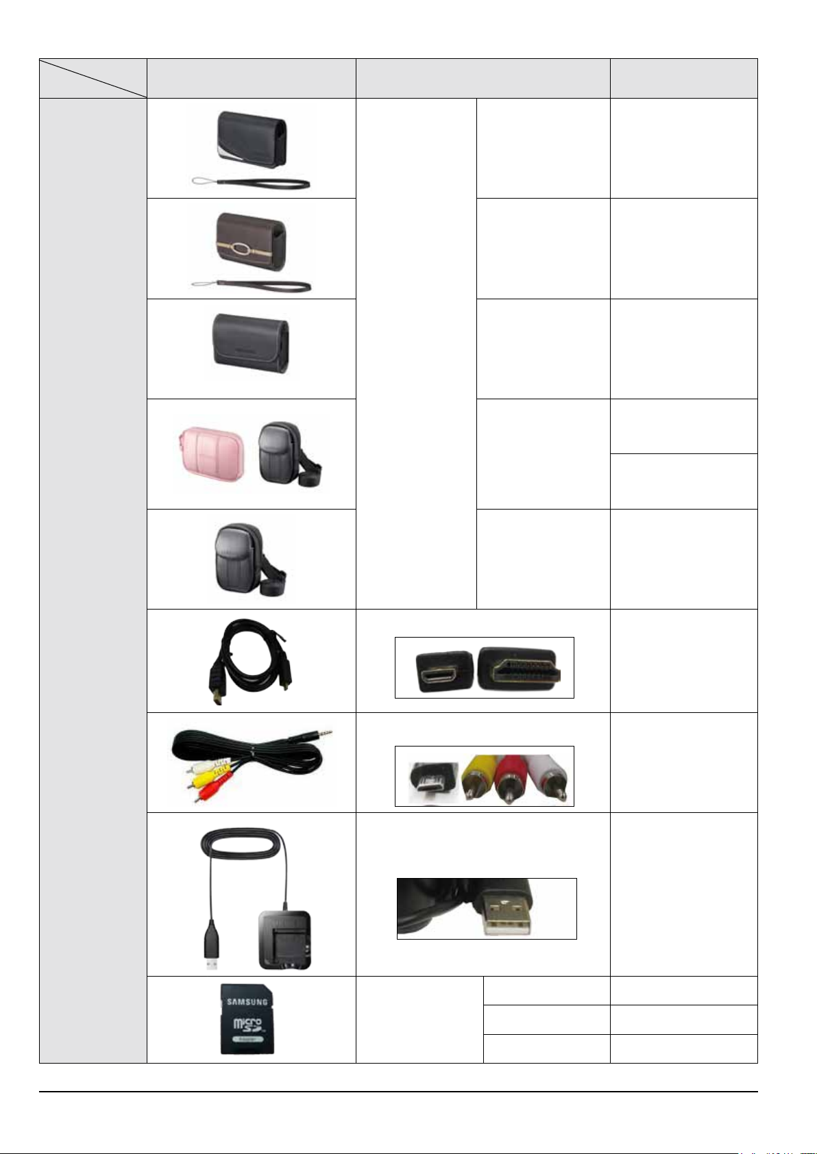
Image Description Parts No.
CC9S70B AD69-03284A
CC9S71N AD69-03285A
Camera case
CC9S30B AD69-03283A
AD69-02964A
CC9U21B/P
Optional
items
AD69-03010A
CC9U11B AD69-02397B
HDMI cable
-
A/V cable
AD39-00146A
Battery charger
2-4
Memory card
Copyright© 1995-2012 SAMSUNG. All rights reserved.
AD44-00176A
2GB 1109-001446
4GB 1109-001420
8GB 1109-001396
Page 12
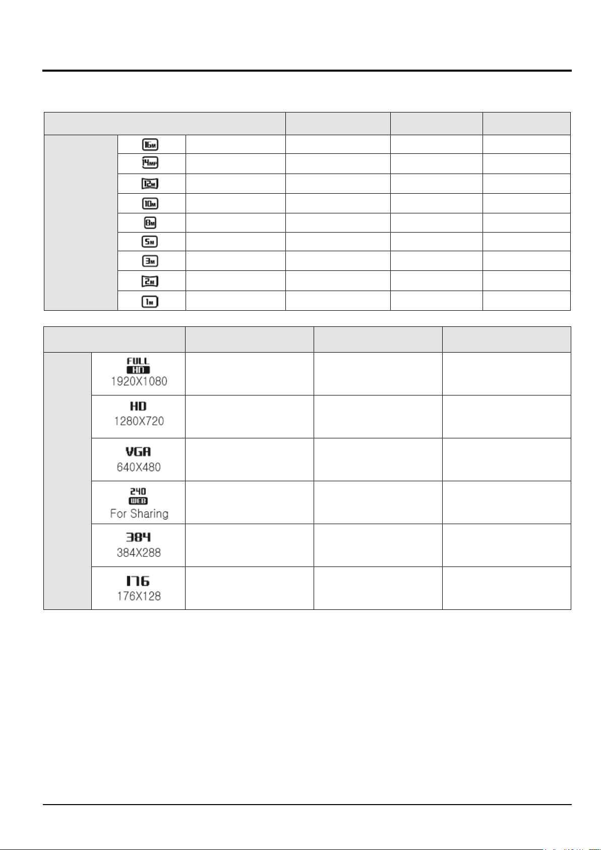
2-4 About the memory card
The memory capacity may differ depending on shooting scenes or shooting conditions.
These capacities are based on a 2 GB SD card (Number of photos).
Size Super Fine Fine Normal
4608 X 3456 244 302 396
4608 X 3072 280 346 452
4608 X 2592 322 396 516
3648 X 2736 380 468 608
Product specications
Photo
Video
2832 X 2832 468 572 738
2592 X 1944 708 856 1,086
1984 X 1488 1,106 1,318 1,626
1920 X 1080 1,452 1,702 2,058
1024 X 768 2,674 2,980 3,364
Size 480fps 240fps 30fps
- - Approx. 17’ 30’’
- - Approx. 26’ 06’’
- - Approx. 51’ 30’’
- - Approx. 300’
- Approx. 43’ 28’’ -
Approx. 29’ 10’’ - -
*The gures above are measured without using the zoom function. Available recording time may vary if you use the zoom.
Several videos were recorded in succession to determine the total recording time.
Copyright© 1995-2012 SAMSUNG. All rights reserved.
2-5
Page 13
Product specications
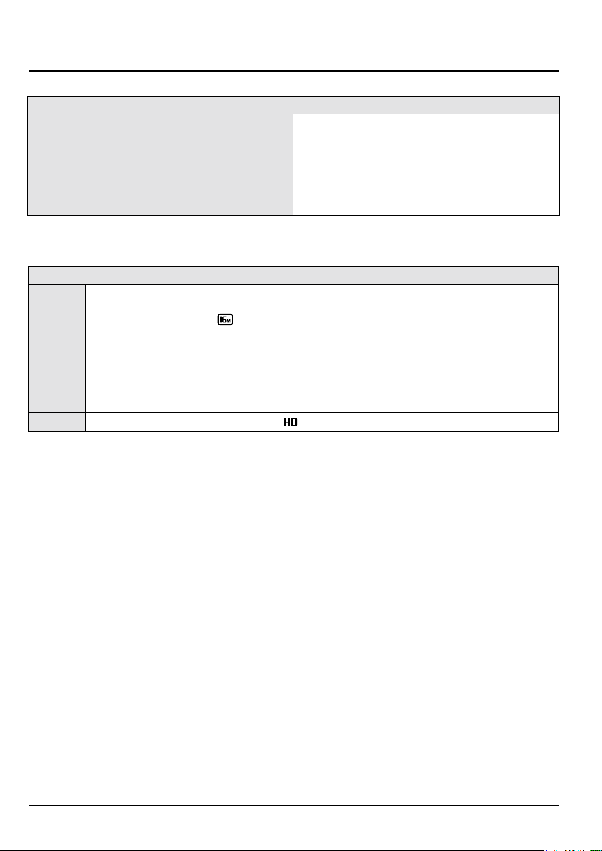
2-5 About the battery
<Battery specications>
Specication Description
Model SLB-10A
Type Lithium-ion battery
Cell capacity 1030 mAh
Voltage 3.7 V
Charging time
*(when the camera is switched off)
* Charging the battery by connecting it to a computer may take longer.
<Battery life>
Average shooting time/ Number of photos Test conditions (when the battery is fully charged)
The battery life was measured under the following conditions: in
resolution, Fine quality, OIS on.
Photos
Videos Approximately 90 min
• The gures above are measured by Samsung’s standards. Your results may differ, depending on your actual usage.
• Several videos were recorded in succession to determine the total recording time.
• When using network functions, the battery will be depleted more quickly.
• The above values are measured while the GPS is off.
Approximately 120 min/
Approximately 220 photos
1. Set the ash option to Fill in, take a single shot, and zoom in or out.
2. Set the ash option to Off, take a single shot, and zoom in or out.
3. Perform steps 1 and 2, waiting 30 seconds between each step.
Repeat the process for 5 minutes, and then turn off the camera for 1 minute.
4. Repeat steps 1 to 3.
Record videos at
resolution and 30 FPS.
Approximately 240 min
P mode, in darkness,
2-6
Copyright© 1995-2012 SAMSUNG. All rights reserved.
Page 14

3. Disassembly and Reassembly
3-1 Screw parts list
Page No. Type Part No. Qty
Disassembly and Reassembly
3-2
3-4
3-5
3-11
SCREW MACHINE
SCREW MACHINE
SCREW TAPTYPE
SCREW TAPTYPE
6001-002152 6
6001-002152 1
6003-001717 5
6003-001288 3
<Table 3-1>
Copyrightⓒ 1995-2012 SAMSUNG. All rights reserved.
3-1
Page 15
Disassembly and Reassembly
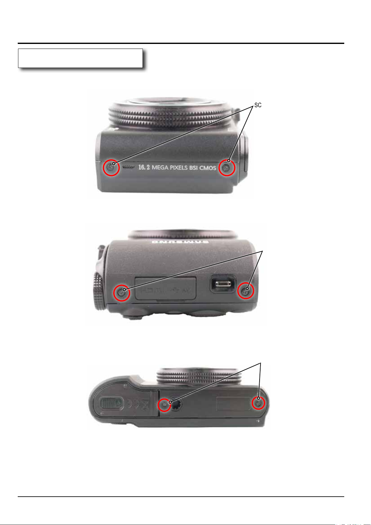
3-2 Camera Disassembly
1. SCREW from the main unit
1) Remove the 6 screws from the main unit.
SCREW MACHINE
SCREW MACHINE
SCREW MACHINE
3-2
Fig. 3-1
Copyrightⓒ 1995-2012 SAMSUNG. All rights reserved.
Page 16
Disassembly and Reassembly
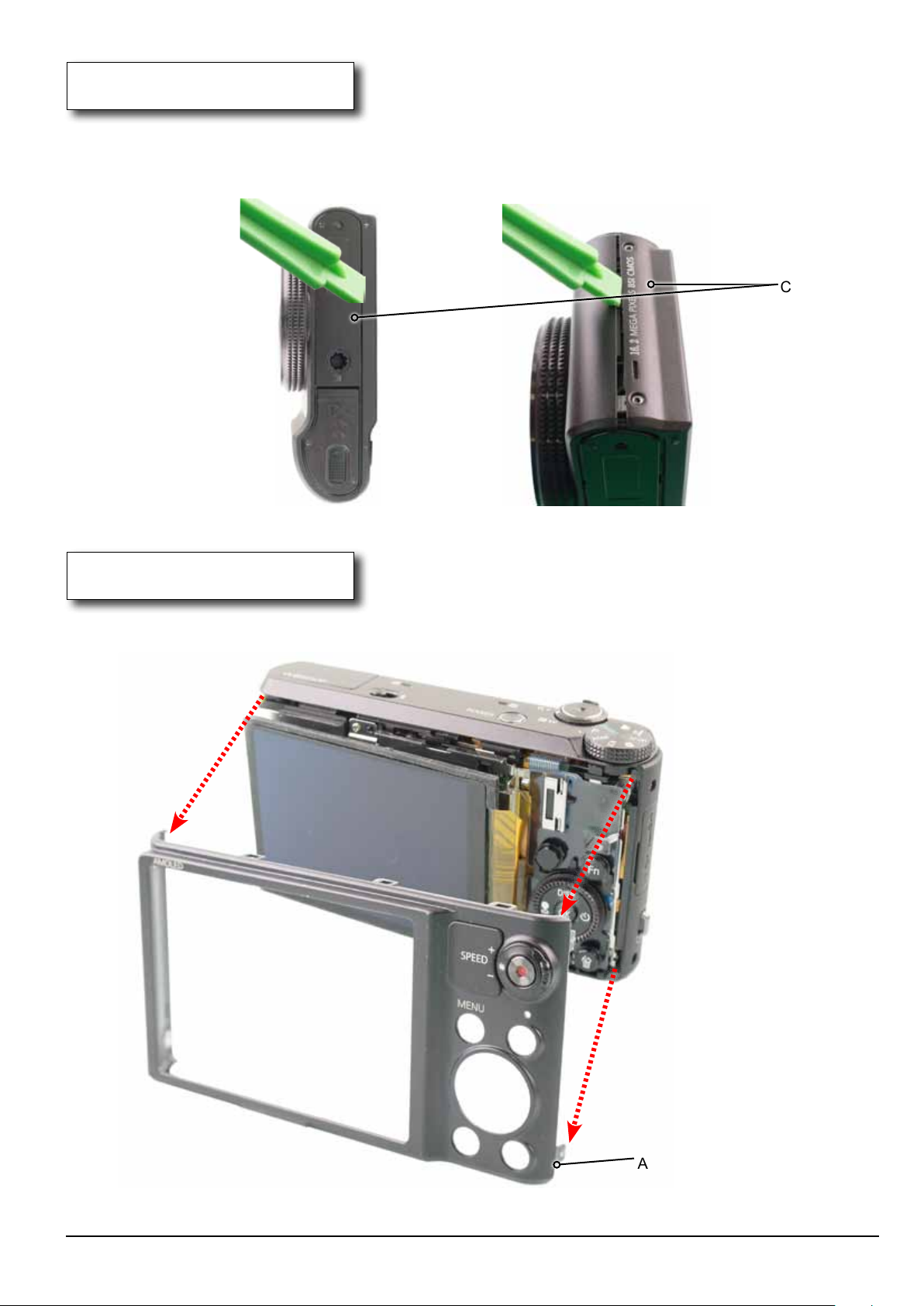
2. COVER
1) Run a safe open pry tool around the join of locking structure part to release the COVER located
on the bottom first. Then remove the COVER located on the side as illustrated in image below.
Slightly wiggle the locking structure part to widen the gap. You'll have to apply a little force to remove it.
1 2
COVER
Fig. 3-2
3. ASSY COVER BACK
1) Remove the ASSY COVER BACK in the direction of the arrow.
Fig. 3-3
Copyrightⓒ 1995-2012 SAMSUNG. All rights reserved.
ASSY COVER BACK
3-3
Page 17
Disassembly and Reassembly
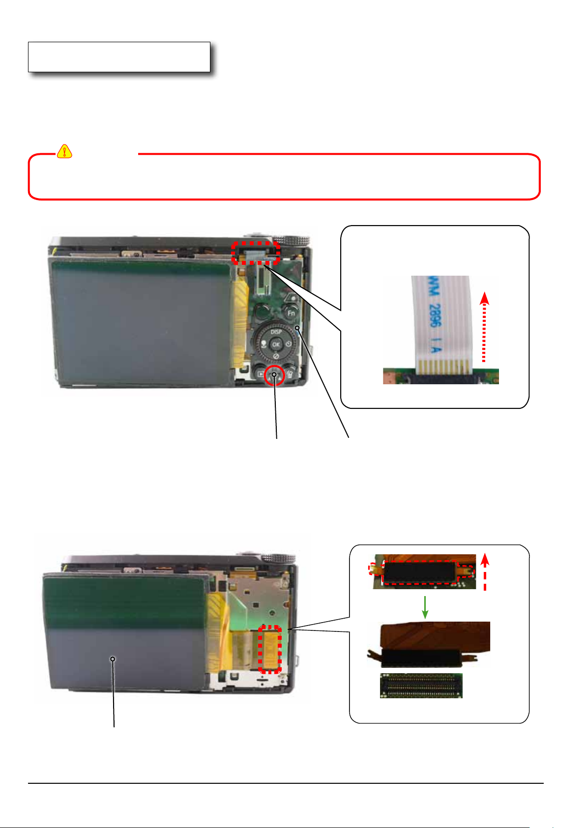
4. ASSY AMOLED 3.0"
1) Remove the screw. Remove the FPCB from the connector as illustrated in image A.
Then remove the KEY FPCB.
!
CAUTION
Make sure not to fold the other area except the board of KEY FPCB when remoing and installint
the KEY FPCB.
FPCB
Image A
SCREW MACHINE KEY FPCB
Fig. 3-4
2) Remove the FPCB from the connector in the direction of the arrow as illustrated in image B.
Then, remove the ASSY LCD.
3-4
FPCB
Image B
ASSY LCD
Fig. 3-5
Copyrightⓒ 1995-2012 SAMSUNG. All rights reserved.
Page 18
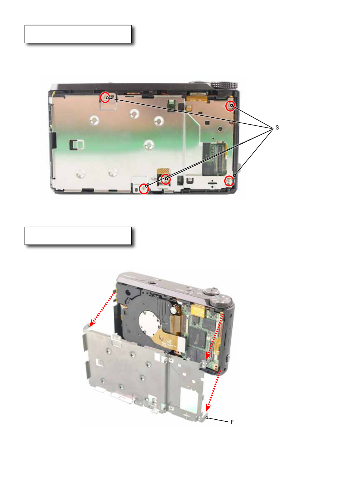
5. FRAME MAIN SCREW
1) Remove the 5 screws from the FRAME MAIN.
Disassembly and Reassembly
SCREW TAPTYPE
Fig. 3-6
6. FRAME MAIN
1) Remove the FRAME MAIN in the direction of the arrow.
Fig. 3-7
Copyrightⓒ 1995-2012 SAMSUNG. All rights reserved.
FRAME MAIN
3-5
Page 19
Disassembly and Reassembly
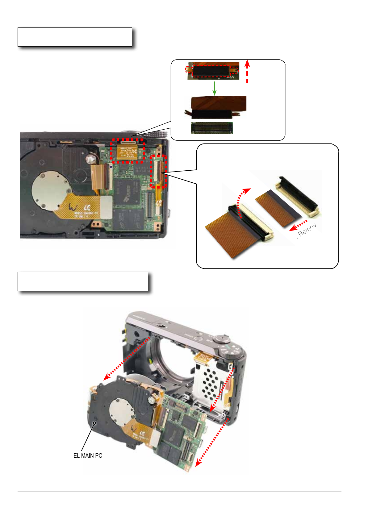
7. FPCB
1) Remove the FPCB from the connector as illustrated in image A and B.
FPCB
Image A
Connector
CONNECTOR
1. Open.
Fig. 3-8
8. ASSY BARREL MAIN PCB
1) Remove the ASSY BARREL MAIN PCB in the direction of the arrow.
FPCB
Connector
FPCB
2. Remove.
Image B
3-6
ASSY BARREL MAIN PCB
Fig. 3-9
Copyrightⓒ 1995-2012 SAMSUNG. All rights reserved.
Page 20
Disassembly and Reassembly
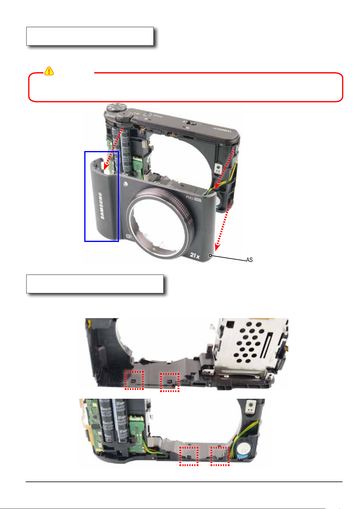
9. ASSY COVER FRONT
1) Remove the ASSY COVER FRONT in the direction of the arrow.
!
CAUTION
Make sure to lift up the part around the USB/HDMI connector area first indicated in blue box
when removing the ASSY COVER FRONT. Be sure to install the part around the USB/HDMI
connector area first.
10. LOCKING STRUCTURE PART
1) Remove the 4 LOCKING structure parts.
ASSY COVER FRONT
Fig. 3-10
Fig. 3-11
Copyrightⓒ 1995-2012 SAMSUNG. All rights reserved.
3-7
Page 21
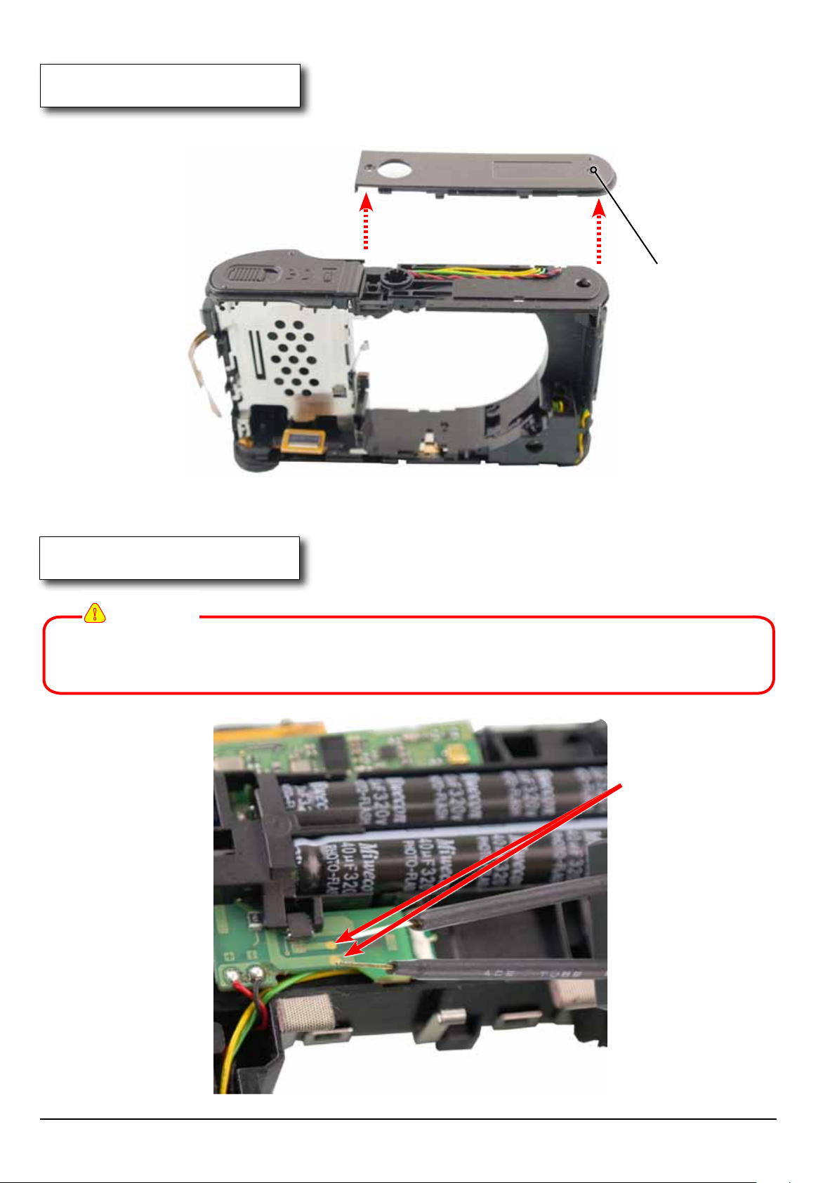
Disassembly and Reassembly
11. COVER BOTTOM
1) Remove the COVER BOTTOM in the direction of the arrow
COVER BOTTOM
Fig. 3-12
12. DISCHARGING
!
CAUTION
Make sure to discharge the area not being soldered on WiFi-strobo PCB
according to the instructions as illustrated.
Discharging
3-8
Fig. 3-13
Copyrightⓒ 1995-2012 SAMSUNG. All rights reserved.
Page 22
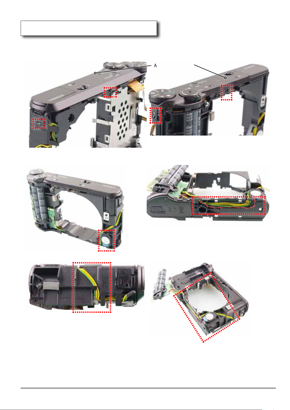
Disassembly and Reassembly
13. LOCKING STRUCTURE PART / WIRE
1) Remove the 4 LOCKING structure parts and remove the wire as illustrated in image below.
ASSY COVER TOP
Fig. 3-14
Copyrightⓒ 1995-2012 SAMSUNG. All rights reserved.
3-9
Page 23
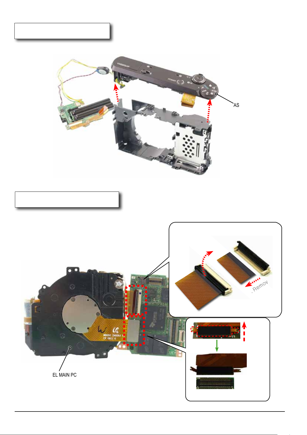
Disassembly and Reassembly
14. ASSY COVER TOP
1) Remove the ASSY COVER TOP in the direction of the arrow.
ASSY COVER TOP
Fig. 3-15
15. FPCB
1) Remove the FPCB from the connectora s illustrated in image A and B. Then remove the FPCB
from the ASSY BARREL MAIN PCB
CONNECTOR
Connector
1. Open.
FPCB
Connector
FPCB
2. Remove
Image A
ASSY BARREL MAIN PCB
3-10
FPCB
Fig. 3-16
Image B
Copyrightⓒ 1995-2012 SAMSUNG. All rights reserved.
Page 24
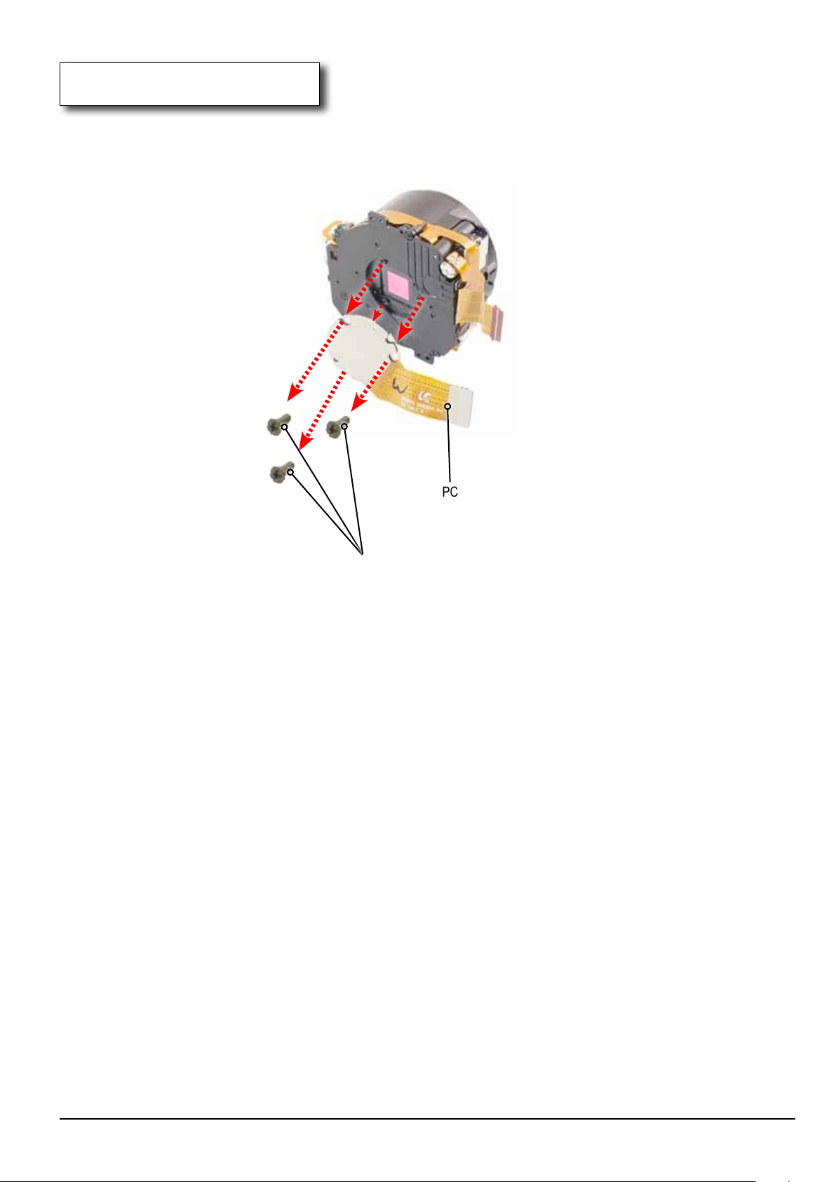
16. CMOS FPCB ASSY
1) Remove the 3 screws on the BARREL. Then remove the CMOS FPCB ASSY.
Disassembly and Reassembly
CMOS FPCB ASSY
SCREW TAPTYPE
Fig. 3-17
Copyrightⓒ 1995-2012 SAMSUNG. All rights reserved.
3-11
Page 25
Disassembly and Reassembly
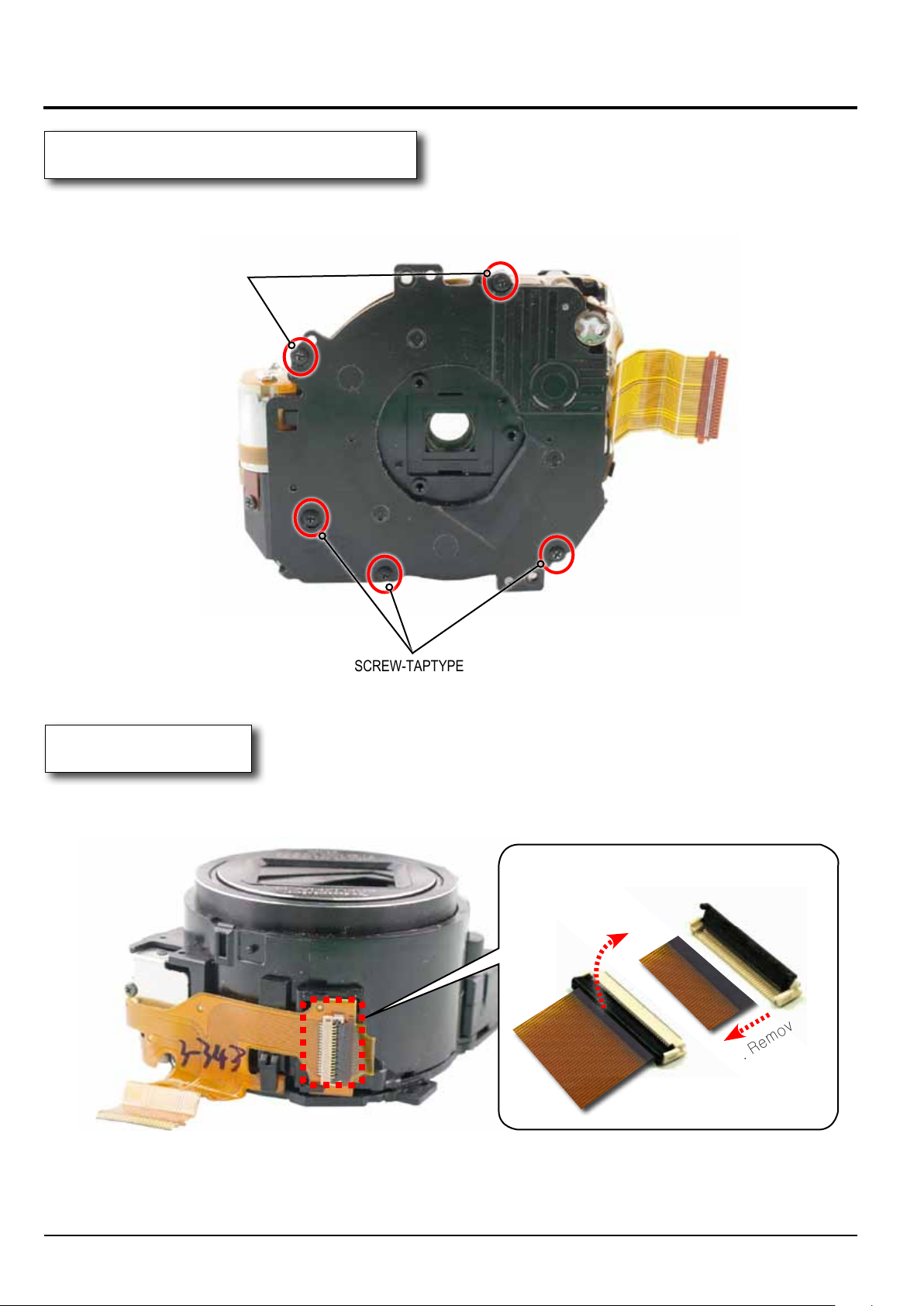
3-3 Barrel Disassembly
1. ASSY LENS BASE-D5 SCREW
1) Remove the 5 screws.
SCREW-TAPTYPE
SCREW-TAPTYPE
Fig. 3-18
2. FPCB
1) Remove the FPCB from the connector as illustrated in image A.
1. Open.
FPCB
Connector
FPCB
CONNECTOR
Connector
2. Remove.
Image A
3-12
Fig. 3-19
Copyrightⓒ 1995-2012 SAMSUNG. All rights reserved.
Page 26
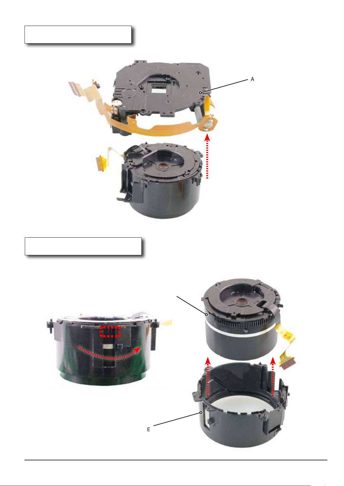
3. ASSY LENS BASE
1) Remove the ASSY LENS BASE in the direction of the arrow.
Disassembly and Reassembly
ASSY LENS BASE
Fig. 3-20
4.BARREL OUTER GUIDE
1) Turn the ripple-shaped part counter-clock wise.
Remove the BARREL BASE from the BARREL OUTER GUIDE in the direction of the arrow.
BARREL BASE
BARREL OUTER GUIDE
Fig. 3-21
Copyrightⓒ 1995-2012 SAMSUNG. All rights reserved.
3-13
Page 27
Disassembly and Reassembly
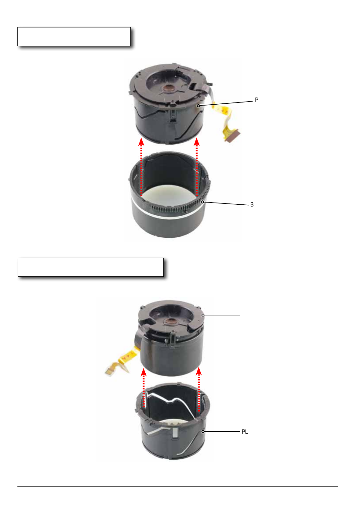
5. BARREL BASE
1) Remove the PLATE-OUTER GUIDE from the BARREL BASE in the direction of the arrow.
PLATE-OUTER GUIDE
BARREL BASE
Fig. 3-22
6. BARREL-OUTER GUIDE
1) Remove the BARREL-OUTER GUIDE from the PLATE-OUTER GUIDE in the direction of the arrow.
BARREL-OUTER GUIDE
3-14
PLATE-OUTER GUIDE
Fig. 3-23
Copyrightⓒ 1995-2012 SAMSUNG. All rights reserved.
Page 28
Disassembly and Reassembly
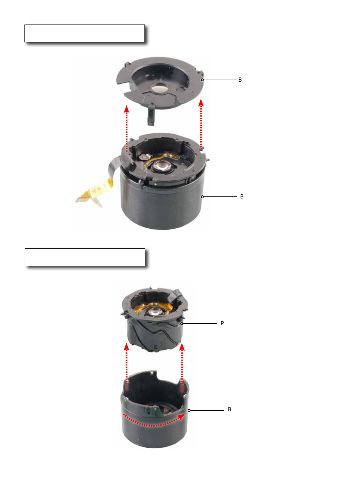
7. BARREL-OUTER GUIDE
1) Remove the BARREL-OUTER GUIDE from the BARREL-OUTER GUIDE PLATE in the direction of the arrow.
BARREL-OUTER GUIDE
BARREL-OUTER GUIDE PLATE
Fig. 3-24
8. PLATE-INNER GUIDE
1) Turn the
Remove the PLATE-INNER GUIDE from the BARREL ZOOM in the direction of the arrow.
BARREL ZOOM clock wise.
PLATE-INNER GUIDE
Fig. 3-25
Copyrightⓒ 1995-2012 SAMSUNG. All rights reserved.
BARREL ZOOM
3-15
Page 29
Disassembly and Reassembly
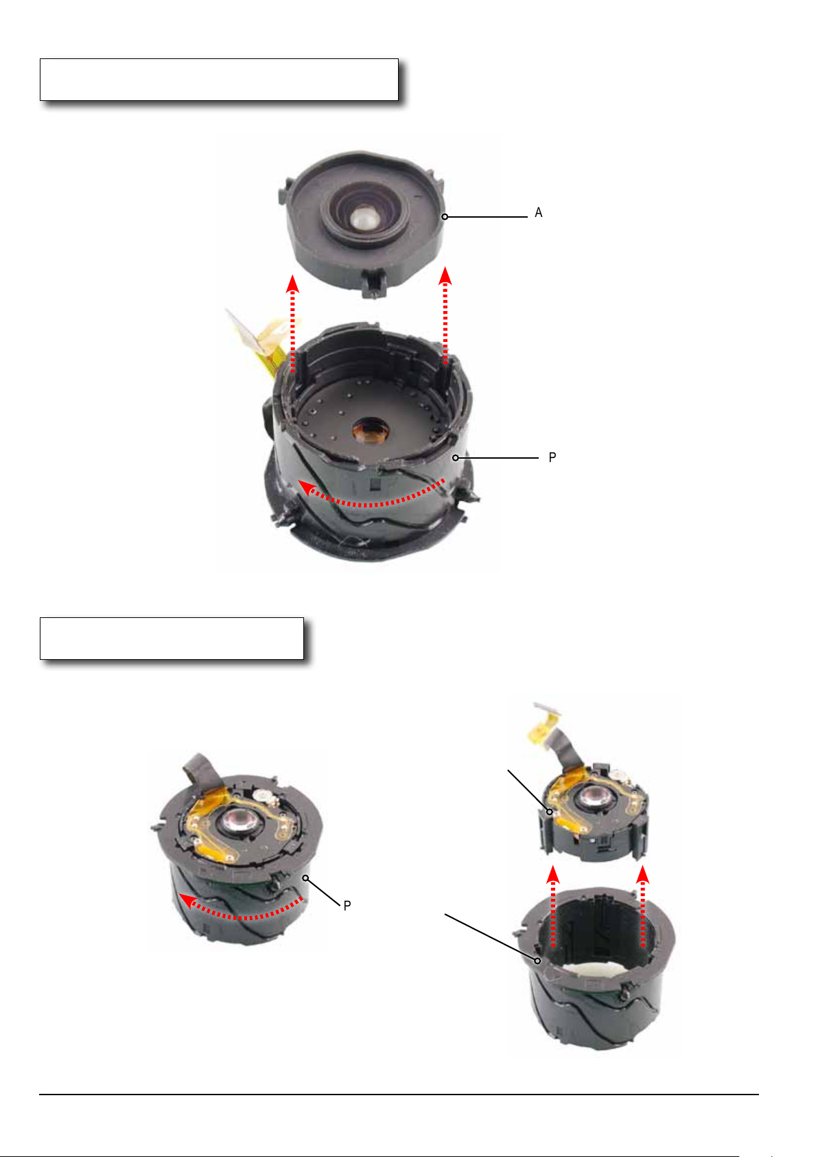
9. ASSY SUB BARREL-ZOOMRING
1) Turn the PLATE-INNER GUIDE clock wise.
Remove the ASSY SUB BARREL-ZOOMRING from the PLATE-INNER GUIDE in the direction of the arrow.
ASSY SUB BARREL-ZOOMRING
PLATE-INNER GUIDE
Fig. 3-26
10. BARREL-INNER CAM
1) Turn the PLATE-INNER GUIDE clock wise.
Remove the BARREL-INNER CAM from the PLATE-INNER GUIDE in the direction of the arrow.
BARREL-INNER CAM
3-16
PLATE-INNER GUIDE
Fig. 3-27
Copyrightⓒ 1995-2012 SAMSUNG. All rights reserved.
Page 30
Disassembly and Reassembly
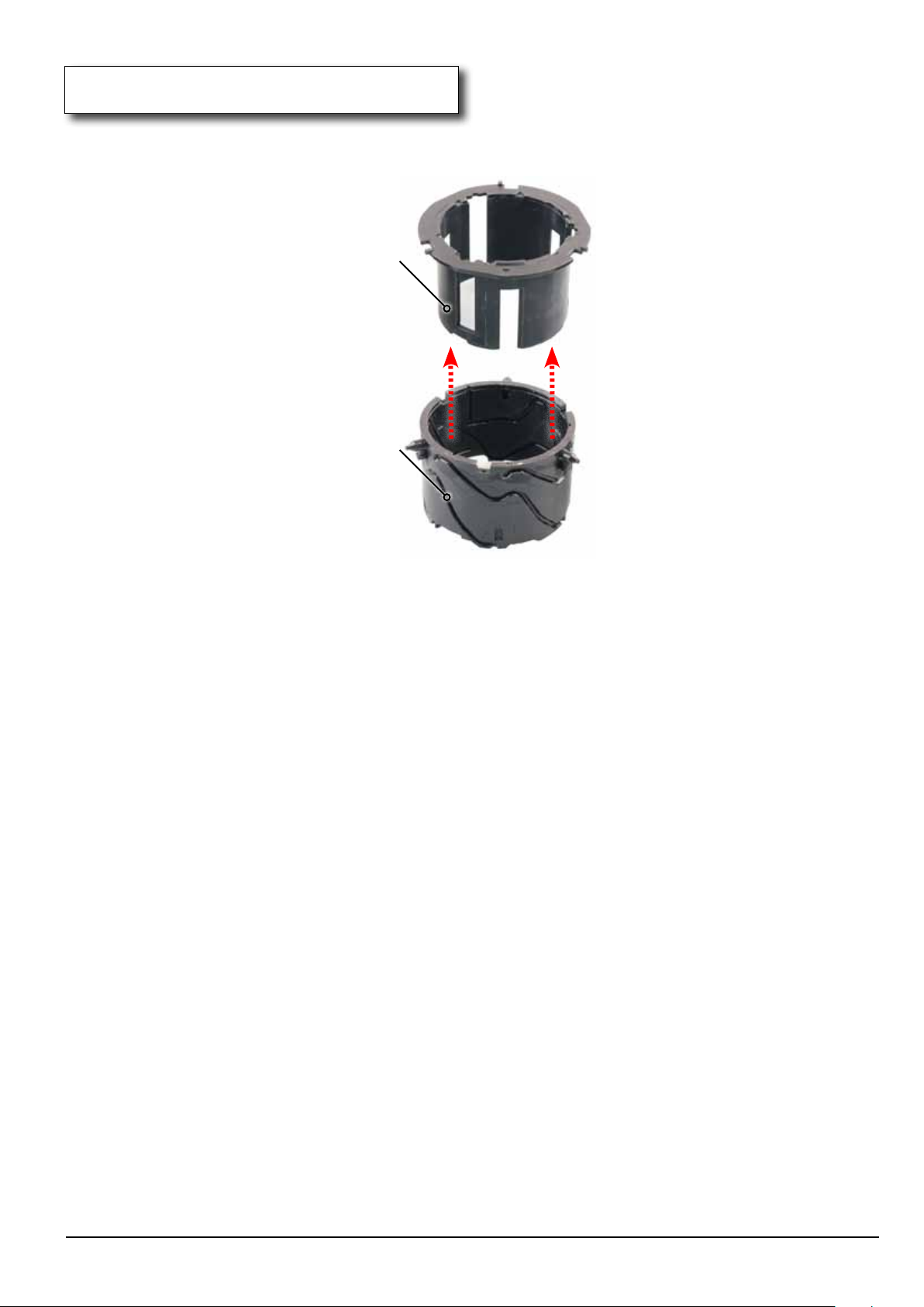
11. ASSY SUB BARREL-2ND_OIS
1) Remove the ASSY SUB BARREL-2ND_OIS from the PLATE-INNER GUIDE in the direction of the arrow.
ASSY SUB BARREL-2ND_OIS
PLATE-INNER GUIDE
Fig. 3-28
Copyrightⓒ 1995-2012 SAMSUNG. All rights reserved.
3-17
Page 31
Disassembly and Reassembly
3-4 Barrel Reassembly
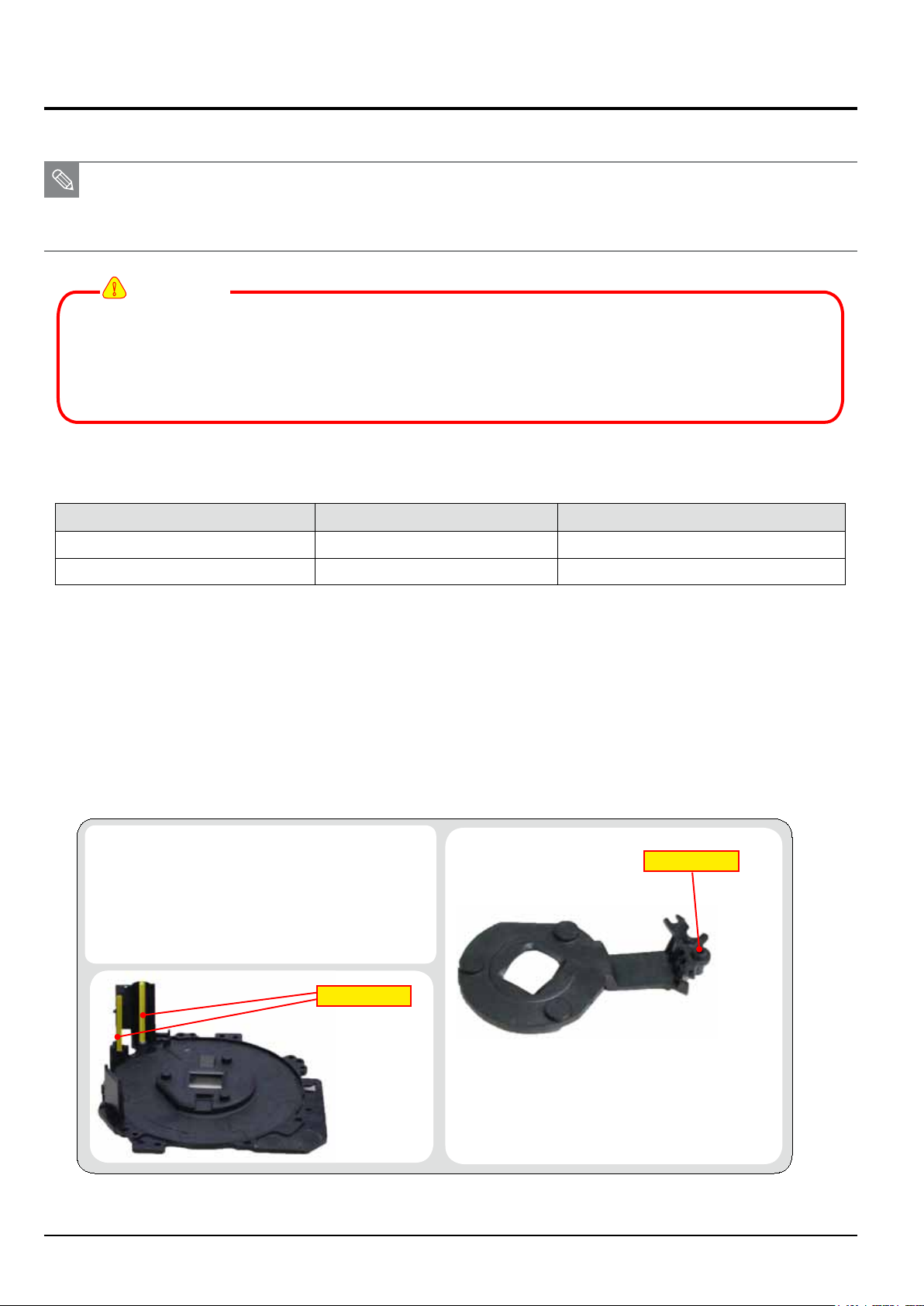
3-4-1 How to use the anti-friction lubricant to barrel assembly
■ Anti-friction lubricant serves to prevent from the possibility of defective parts.
■ Replacement parts are required to apply the lubricant before installing the barrel assembly.
!
CAUTION
■ HANARL is volatile product. Keep its container tightly covered.
■ Make sure to shake the HANARL well rst before you use it because it has a lot of particles
in the bottom. (Otherwise it becomes ineective.)
■ Shake the HANARL until there are no lumps at all and apply it with brush.
1. Type of lubricant
Component Name Where to apply Name of lubricant
Lens Base Sliding contact surfaces of AF Lens. Grease NFH-743C
Others components Inside and outside friction surface HANARL UD-420K
■ Lubricant brand name : Kanto Kasei (http://www.kanto-kasei.co.jp/e/index.html)
Please contact us (KIHYUNG CO.,LTD Distributor) by email if you are interested in purchasing.
e-mail : [email protected]
<Table 3-2>
2. Instructions
1) Lubricating with Grease: Lens Base
Apply the Grease to the Lens Base where is the
sliding contact surfaces of AF Lens.
■ Do not get any Grease on the AF lens.
■ Apply a light coating of the Grease and
make sure not to get any on the AF lens
and other components.
Apply Grease
3-18
Apply Grease
Fig. 3-29
Copyrightⓒ 1995-2012 SAMSUNG. All rights reserved.
Page 32
Disassembly and Reassembly
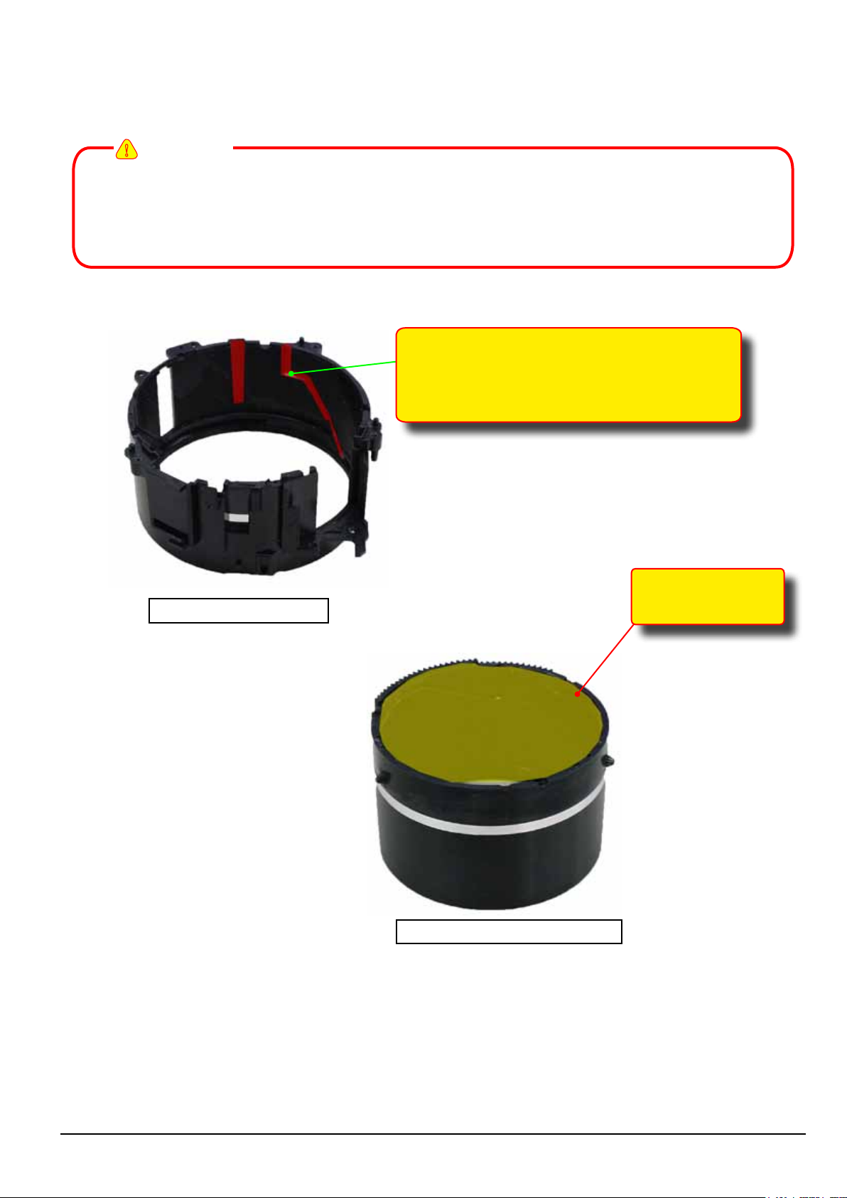
2) Lubricating with HANARL: Others components
Apply the HANARL to the inside and outside friction surface of the components such as ZOOMRING,
CAM BARREL, GUIDE PLATE as illustrated in image below.
!
CAUTION
■ Make sure to shake the HANARL well rst before you use it until there are no lumps.
■ Apply the HANARL with a clean and good-quality brush, making sure the surface is clean.
■ HANARL is volatile product. Keep its container tightly covered.
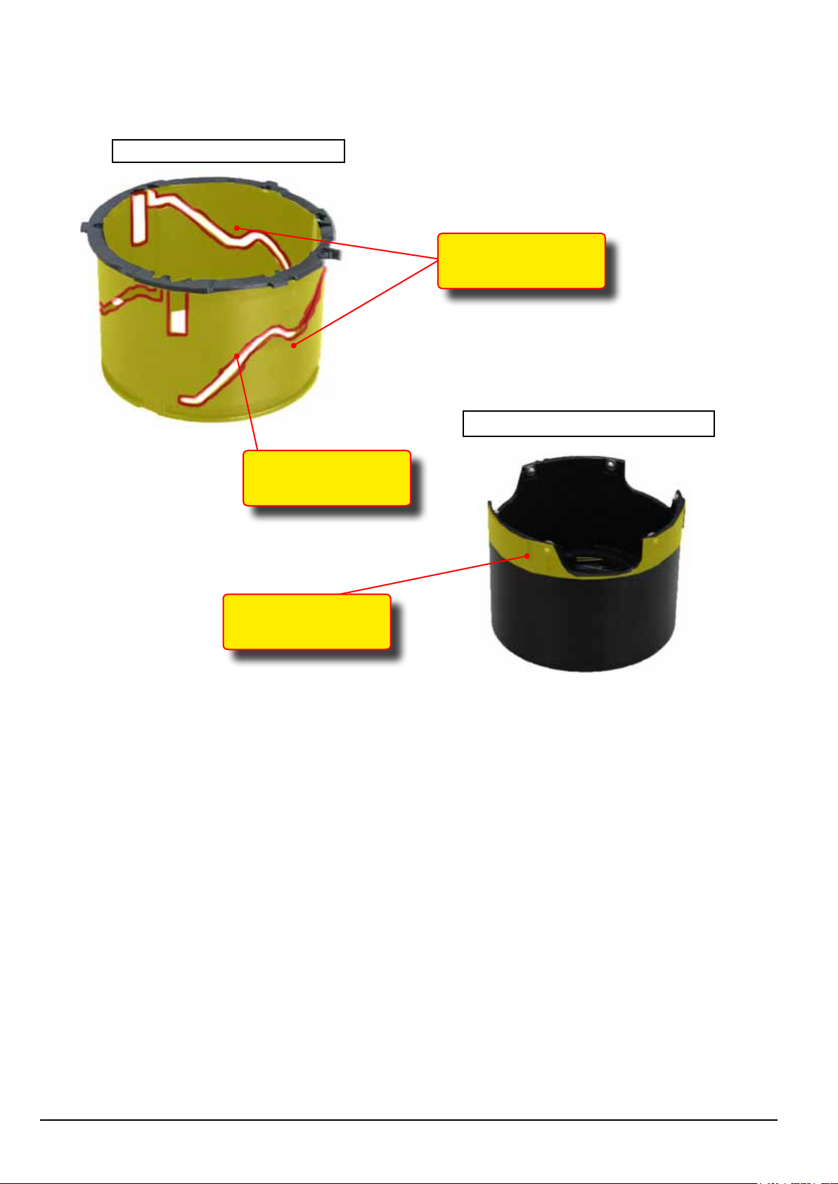
3 points on CAM curve line
and 3 points on straight guide line
indicated in red
BARREL OUTER GUIDE
Inside surface
thoroughly
BARREL BASE
Fig. 3-30
Copyrightⓒ 1995-2012 SAMSUNG. All rights reserved.
3-19
Page 33
Disassembly and Reassembly
PLATE-INNER GUIDE
Inside and outside
surface thoroughly
BARREL ZOOM
Pin sliding
contact surfaces
Outside surface
Fig. 3-31
3-20
Copyrightⓒ 1995-2012 SAMSUNG. All rights reserved.
Page 34
Disassembly and Reassembly
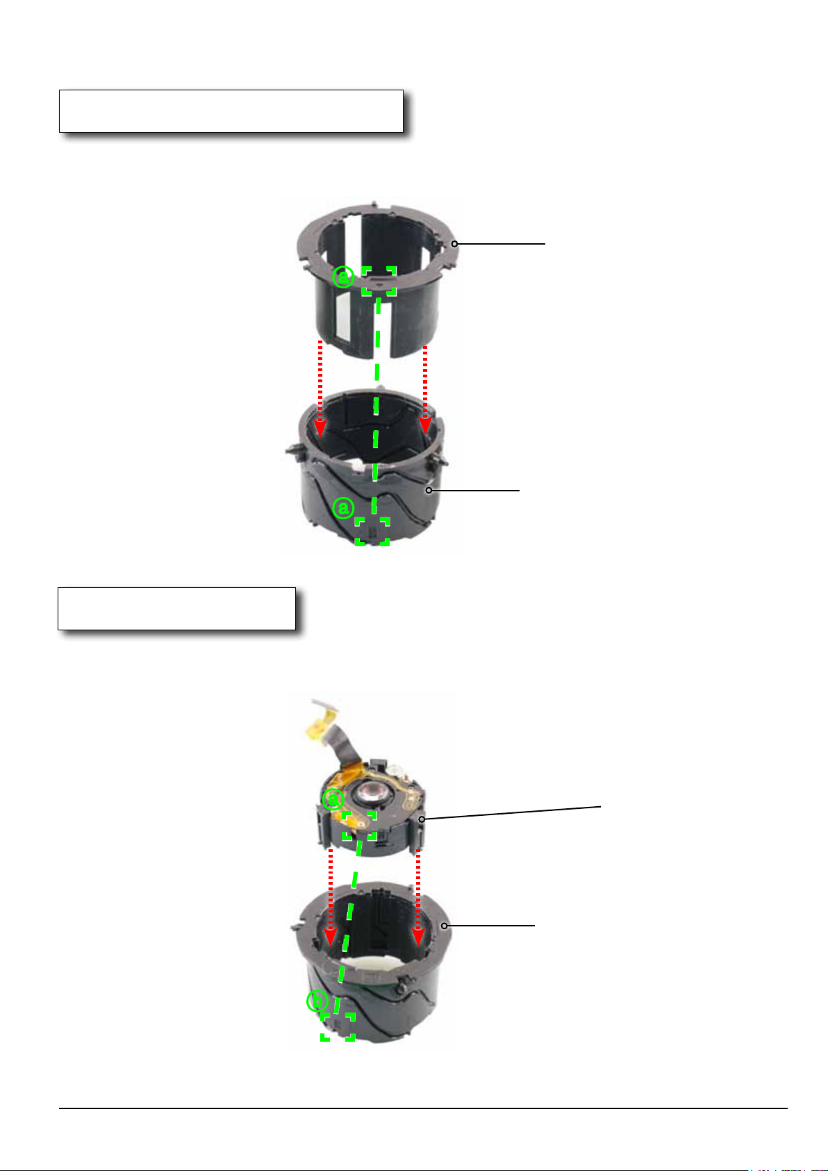
3-4-2 Barrel Reassembly
1. ASSY SUB BARREL-2ND_OIS
1) Align to the point indicated ⓐ.
Then install the PLATE-INNER GUIDE and ASSY SUB BARREL-2ND_OIS in the direction of the arrow.
ASSY SUB BARREL-2ND_OIS
ⓐ
PLATE-INNER GUIDE
ⓐ
Fig. 3-32
2. BARREL-INNER CAM
1) Align the point indicated ⓐ with the point indicated ⓑ.
Then install the ASSY SUB BARREL-2ND_OIS and BARREL-INNER CAM in the direction of the arrow.
ⓐ
BARREL-INNER CAM
ⓑ
Fig. 3-33
Copyrightⓒ 1995-2012 SAMSUNG. All rights reserved.
ASSY SUB BARREL-2ND_OIS
3-21
Page 35
Disassembly and Reassembly
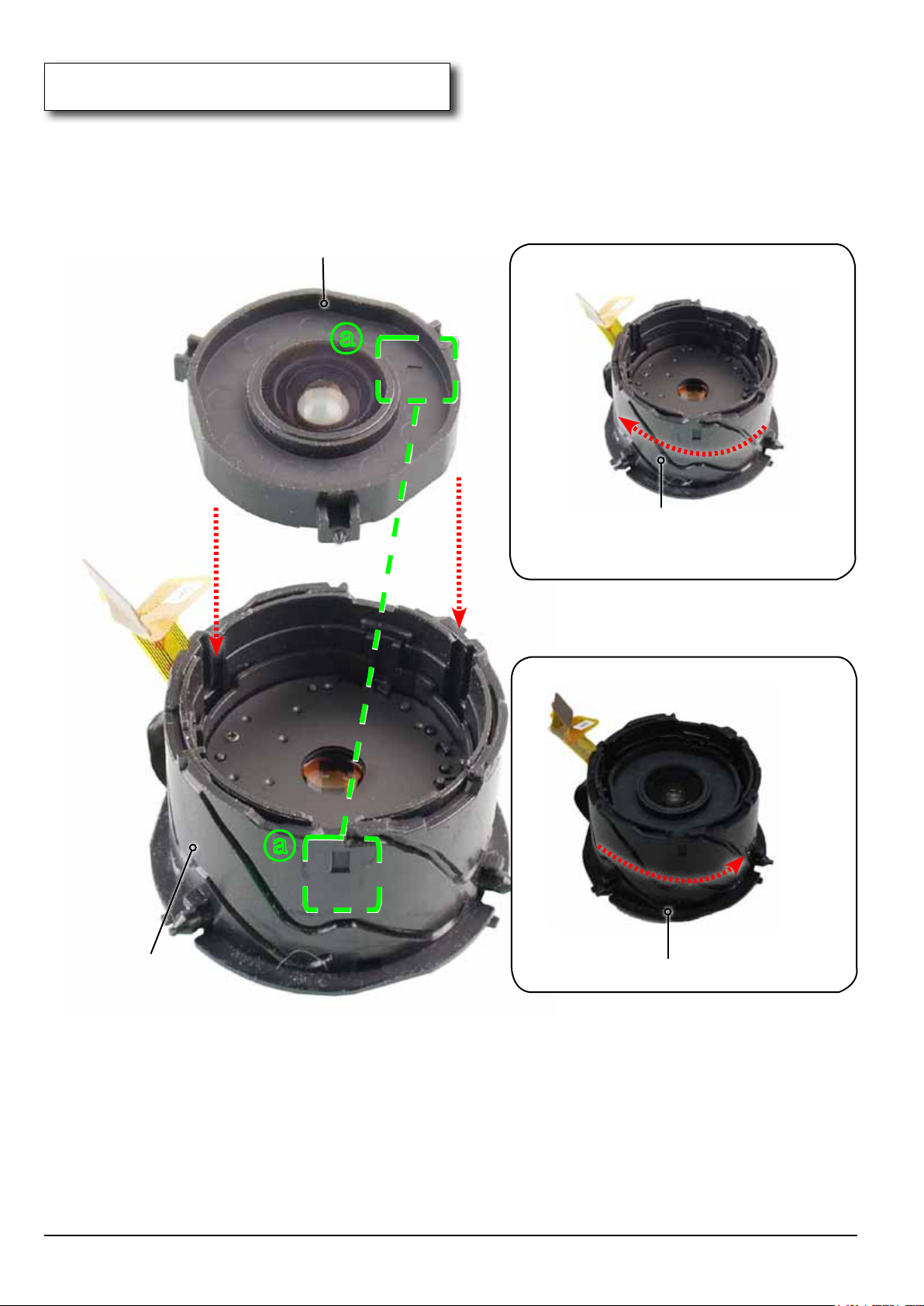
3. ASSY SUB BARREL-ZOOMRING
1) Align to the point indicated ⓐ as illustrated in image below.
Install the LATE-INNER GUIDE and ASSY SUB BARREL-ZOOMRING in the direction of the arrow.
Then turn the PLATE-INNER GUIDE clock wise to the end as illustrated in image A.
Then turn the PLATE-INNER GUIDE counter-clock wise to the end just enough to hold the unit
into the position as illustrated in image B.
ASSY SUB BARREL-ZOOMRING
ⓐ
PLATE-INNER GUIDE
ⓐ
PLATE-INNER GUIDE
PLATE-INNER GUIDE
Image A
Image B
3-22
Fig. 3-34
Copyrightⓒ 1995-2012 SAMSUNG. All rights reserved.
Page 36
Disassembly and Reassembly
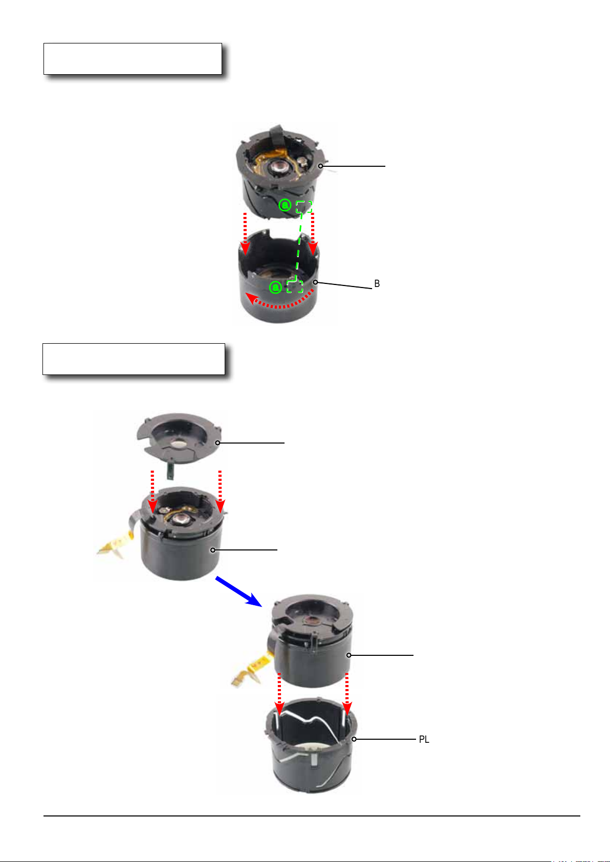
4. PLATE-INNER GUIDE
1) Align to the point indicated ⓐ. Then install the BARREL ZOOM and PLATE-INNER GUIDE
in the direction of the arrow. Then turn the BARREL ZOOM clock wise to the end.
PLATE-INNER GUIDE
ⓐ
ⓐ
Fig. 3-35
BARREL ZOOM
5. PLATE-OUTER GUIDE
1) Install the BARREL ZOOM and BARREL-OUTER GUIDE in the direction of the arrow.
Then install the PLATE-OUTER GUIDE and BARREL ZOOM in the direction of the arrow.
BARREL-OUTER GUIDE
BARREL ZOOM
Fig. 3-36
Copyrightⓒ 1995-2012 SAMSUNG. All rights reserved.
BARREL ZOOM
PLATE-OUTER GUIDE
3-23
Page 37
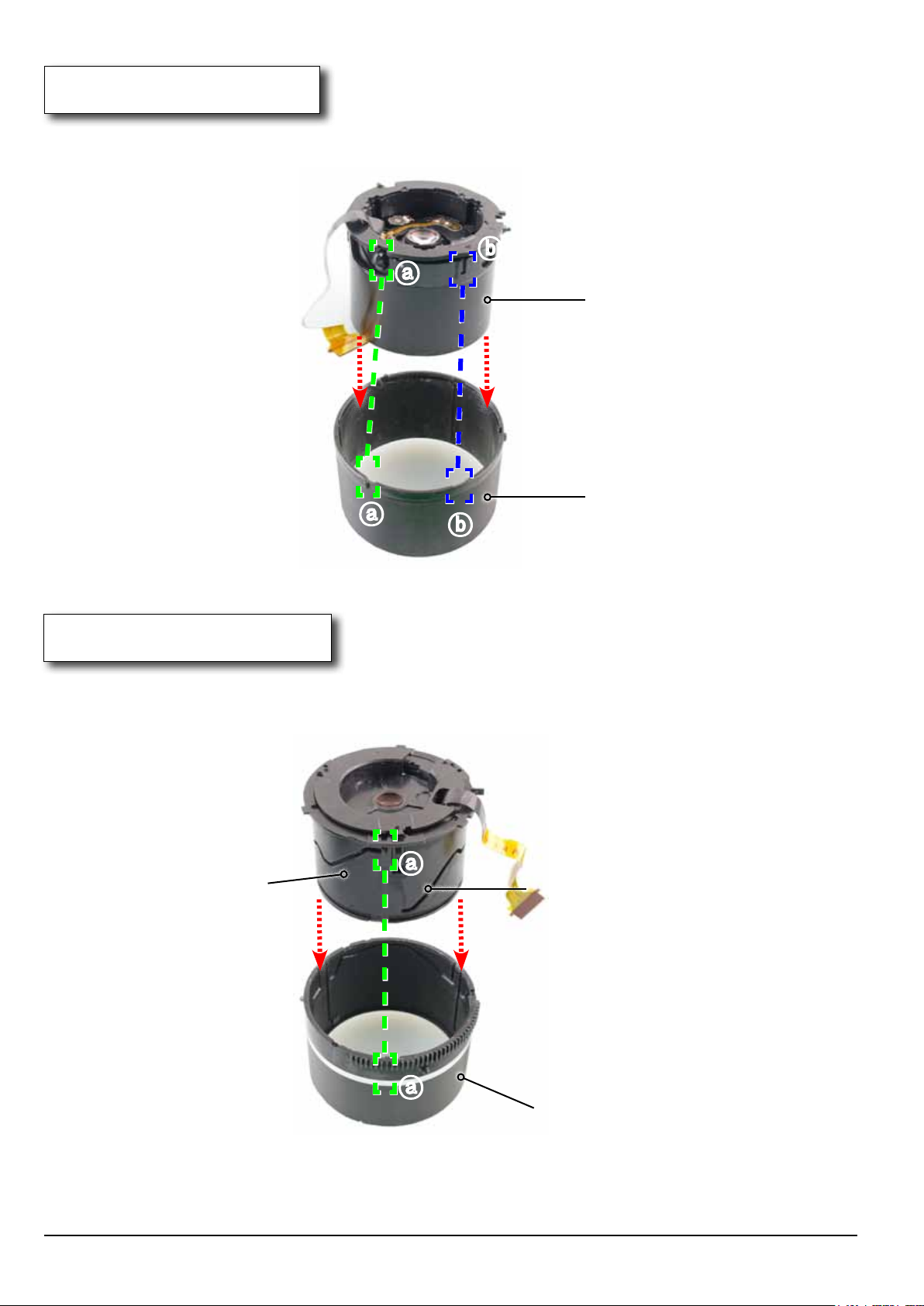
Disassembly and Reassembly
6. BARREL-OUTER
1) Align to the two points indicated ⓐ and ⓑ respectively. Then install the BARREL-OUTER
and BARREL ZOOM in the direction of the arrow.
ⓑ
ⓐ
BARREL ZOOM
BARREL-OUTER
ⓐ
7. BARREL BASE
1) Align to the point indicated ⓐ. Then install the BARREL BASE and PLATE-INNER GUIDE
in the direction of the arrow.
ⓑ
Fig. 3-37
ⓐ
PLATE-INNER GUIDE
BARREL ZOOM
3-24
ⓐ
BARREL BASE
Fig. 3-38
Copyrightⓒ 1995-2012 SAMSUNG. All rights reserved.
Page 38
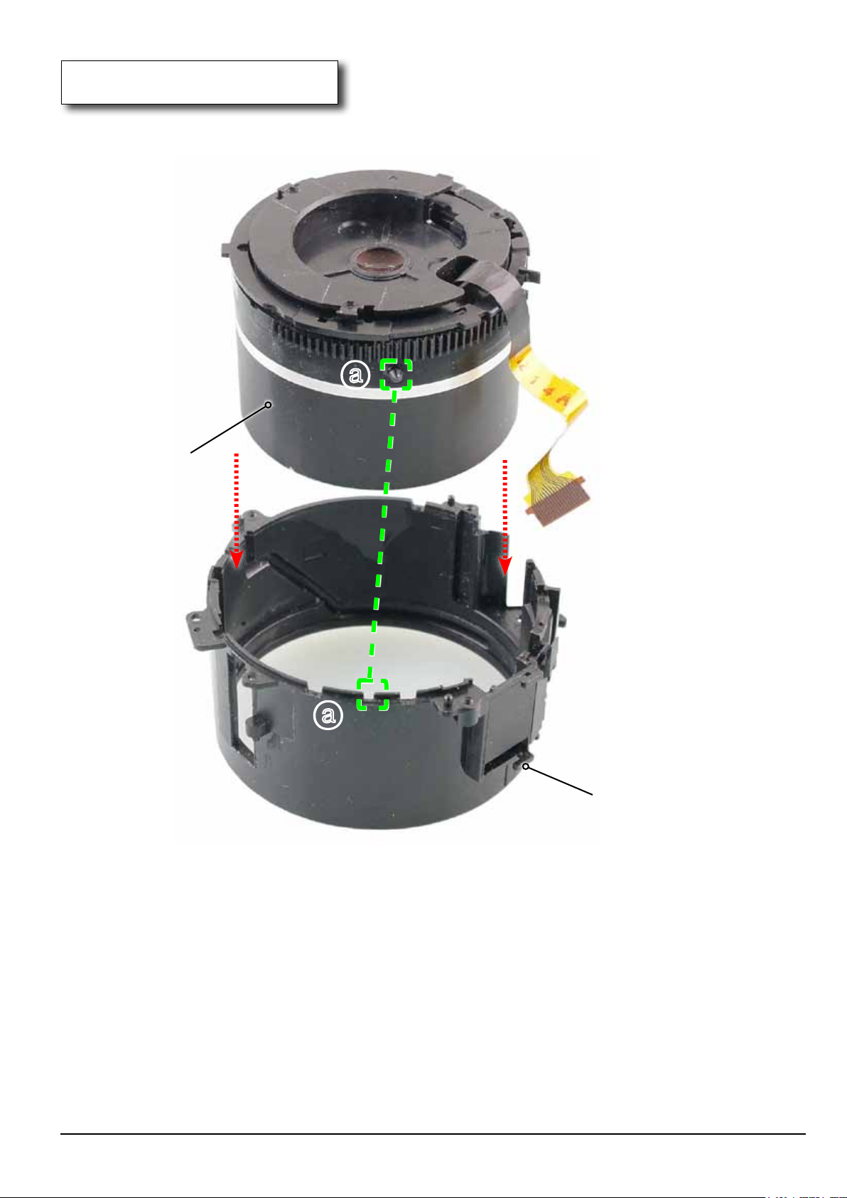
Disassembly and Reassembly
8. BARREL OUTER GUIDE
1) Align to the point indicated ⓐ. Then install the BARREL OUTER GUIDE and BARREL BASE
in the direction of the arrow.
ⓐ
BARREL BASE
ⓐ
BARREL OUTER GUIDE
Fig. 3-39
Copyrightⓒ 1995-2012 SAMSUNG. All rights reserved.
3-25
Page 39
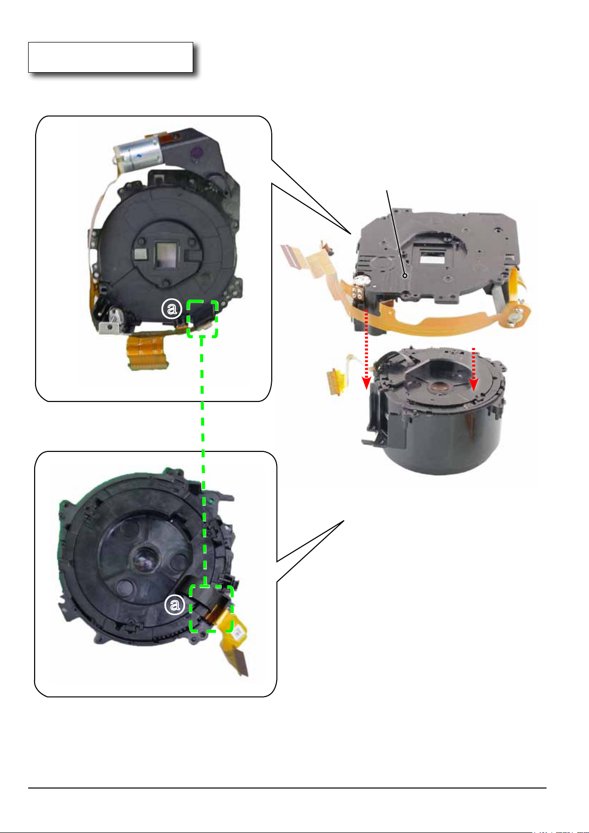
Disassembly and Reassembly
9. ASSY LENS BASE
1) Align to the point indicated ⓐ as illustrated in image A and B.
Then install the ASSY LENS BASE in the direction of the arrow
ⓐ
ASSY LENS BASE
ⓐ
Image A
3-26
Image B
Fig. 3-40
Copyrightⓒ 1995-2012 SAMSUNG. All rights reserved.
Page 40
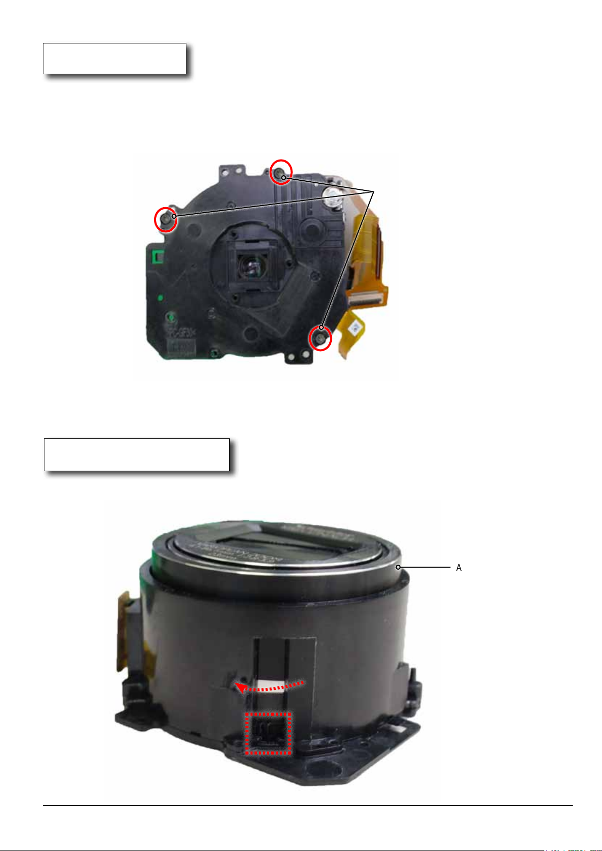
10. SCREW
1) Tighten the 3 screws.
Disassembly and Reassembly
SCREW-TAPTYPE
Fig. 3-41
11. ASSY SHUTTER
1) Insert the BARREL completely. Turn the ripple-shaped part clock wise to the end to close the shutter
completely.
ASSY SHUTTER
Fig. 3-42
Copyrightⓒ 1995-2012 SAMSUNG. All rights reserved.
3-27
Page 41
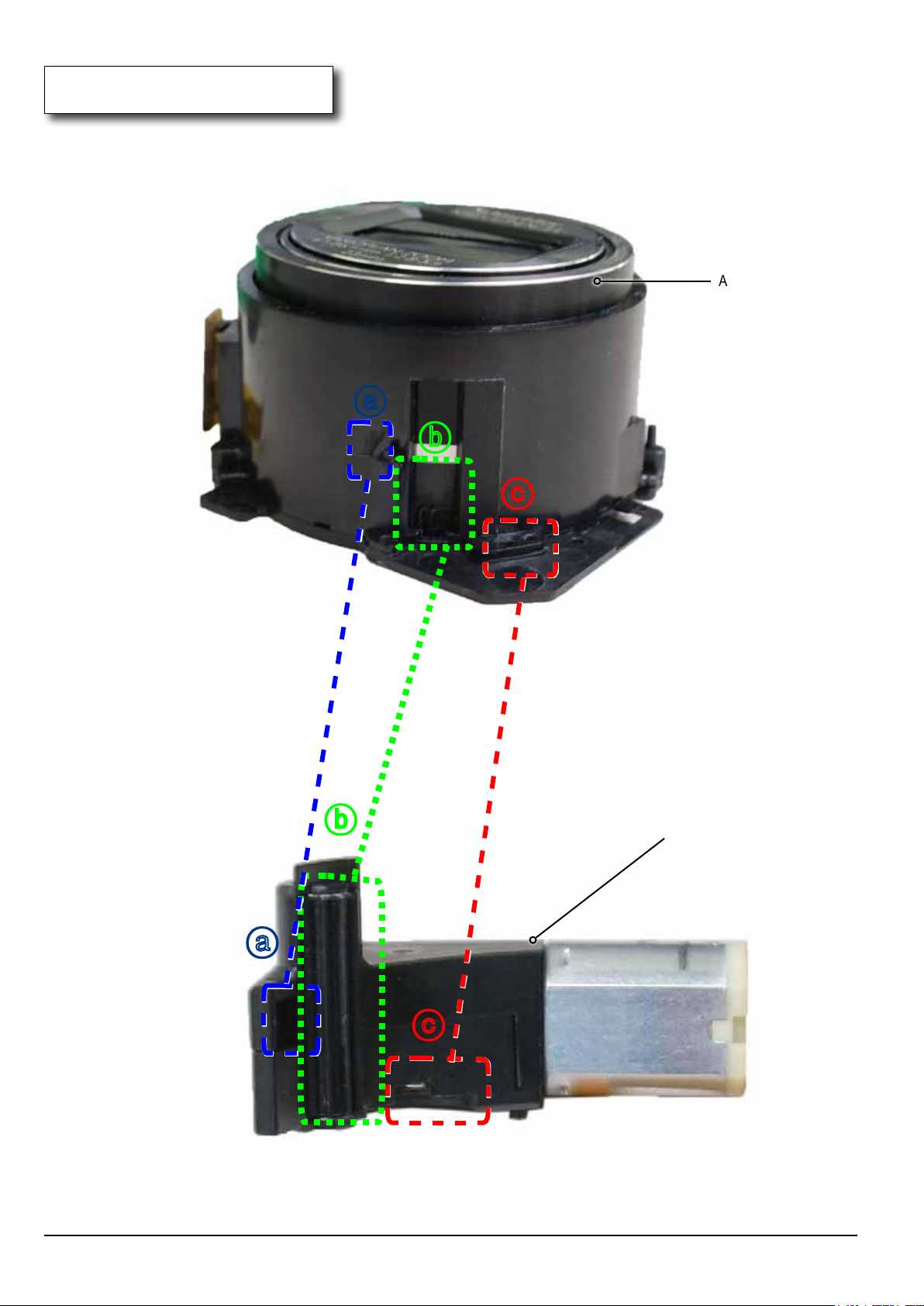
Disassembly and Reassembly
12. ASSY ZOOM MOTER
1) Align to the three points indicated ⓐ,ⓑ and ⓒ respectively. Then install the ASSY ZOOM MOTER.
ASSY SHUTTER
ⓐ
ⓑ
ⓐ
ⓑ
ⓒ
ASSY ZOOM MOTER
3-28
ⓒ
Fig. 3-43
Copyrightⓒ 1995-2012 SAMSUNG. All rights reserved.
Page 42
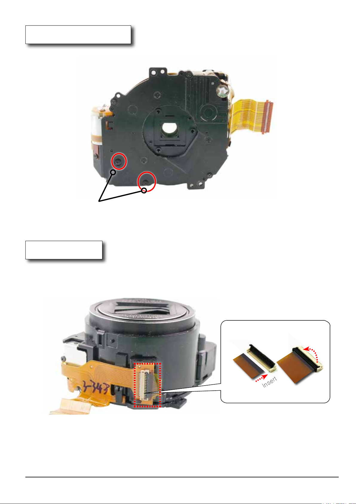
13. ASSY LENS BASE-D5
1) Tighten the 2 screws.
Disassembly and Reassembly
SCREW-TAPTYPE
Fig. 3-44
14. FPCB
1) Connect the FPCB to the connector as illustrated in image A. Solder the FPCB on red posion and install it.
Connector
FPCB
Connector
2. Close.
FPCB
Fig. 3-45
Copyrightⓒ 1995-2012 SAMSUNG. All rights reserved.
1. Insert.
Image A
3-29
Page 43
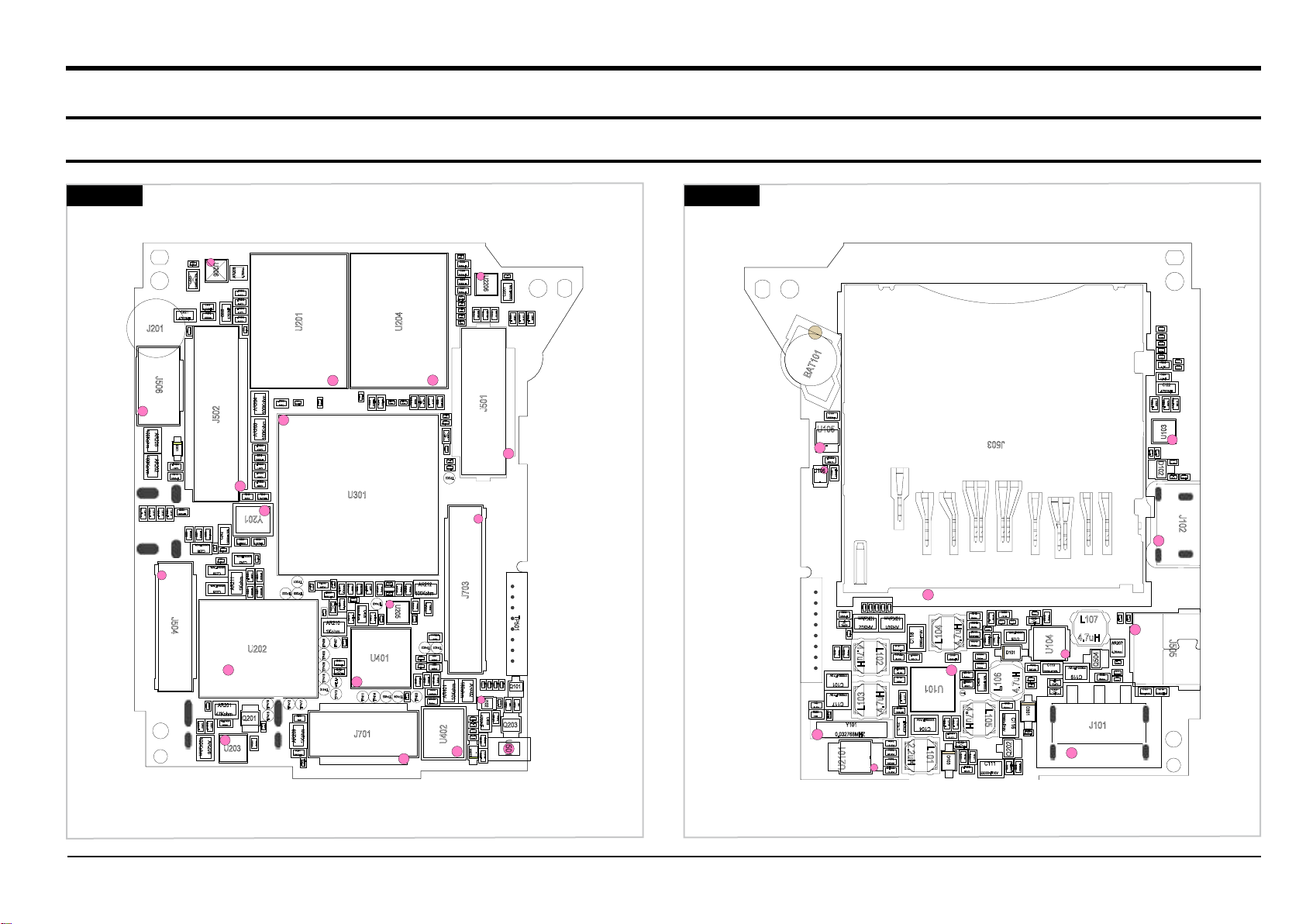
4. PCB diagram
4-1 MAIN PCB
PCB diagrams
TOP
100Kohm
100Kohm
1000nF/10%
C515
J201
AR205
AR202
1000nF
C514
J506
1000nF
C518
1000nF
4700NF
D501
1000nF
C517
C516
1000nF
C519
C520
1000nF
J504
BOTTOM
100nF/10V
C204
C312
0F
AR212
100Kohm
7.5Kohm
0ohm
100nF/10V
C402
100nF/10V
C401
100nF/10V
C405
C407
1000nF
TP403
C208
1000nF
C205
1000nF
C206
1000nF
C207
1000nF
R225
1.2KOHM
100nF/10V
C218
C201
100nF/10V
C209
1.2KOHM
R224
1000nF
C314
C222
8pF/50V
100nF/10V
C318
C313
100nF/10V
C224
0F
NR213
0ohm
100nF/10V
C221
R227
10KOHM
TP202
100nF/10V
U2206
C2191
C2201
10000nF/10%
100nF/10V
NR107
NR106
NR108
0ohm
0ohm
0ohm
1000nF
1000nF
1000nF
C503
C504
J501
C614
BAT101
C131
1000nF
U105
U106
-
1000nF
C132
C130
1000nF
-
J503
0ohm
NR212
0ohm
NR210
0ohm
NR208
0ohm
NR209
0ohm
NR211
NR501
0ohm
R242
0ohm
4.7K
NR502
C324
1.8nF
C122
4700NF
1000nF/10%
1000nF
1000nF
C232
C522
C129
U103
2.2OHM
2.2OHM
R103
R111
C123
D102
100nF/10V
100nF/10V
R123
C125
33KOHM
J102
J703
R402
7.5Kohm
R401
TP401 TP402
20R
R404
20R
R403
180ohm
0ohm
NR406
1000nF
0ohm
NR401
AR401
NR405
10Kohm
0ohm
U402
AR402
C413
100nF/10V
C412
100nF/10V
D2100
TP501
R405
R406
R407
R408
18KOHM
18KOHM
18KOHM
18KOHM
Q101
U102
100KOHM
R105
18K
18K
R203
R205
4700NF
C403
0ohm
NR402
100nF/10V
C411
Q203
100nF/10V
C410
U501
100NF
C2109
C2108
100NF
-
18K
R218
1000MOHM
NCR101
R223
18K
C308
1000nF
0F
C315
C307
100nF/10V
4.7uH
R108
R109
0ohm
0ohm
22000nF/10V
C101
22000nF/10V
C117
Y101
0.032768MHZ
U2101
NR506
0ohm
0ohm
L103
NR509
0ohm
10Kohm
AR502
-
NR505
NR508
0ohm
L102
4.7uH
NR510
0ohm
10Kohm
AR501
L104
C118
R107
22000nF/10V
200KOHM
75Kohm
1000nF
330KOHM
C112
4700NF
2.2uH
C105
C133
1000nF
U101
22000nF/10V
1000nF
1000nF
C103
C114
C104
1000nF
C113
R104
L101
1000MOHM
D103
R110
R115
R114
160K
1000nF
C106
1000nF
C102
0ohm
R2121
0ohm
R2120
0ohm
NR205
1KOHM
R2117
R112
0ohm
NR102
0ohm
FB101
600OHM
NR103
4.7uH
0ohm
NR104
0ohm
1000nF
C120
TP101
4.7uH
0ohm
0ohm
R101
R102
1000nF
C109
NR404
0ohm
NR403
0ohm
C408
22000nF/10V
100KOHM
R116
100nF/10V
C524
C304
2200NF
10000nF/10%
L105
C111
C302
C124
100nF/10V
1000nF
L106
22000nF/10V
300K
NR507
0ohm
R117
C523
0ohm
NR101
C305
0F
100nF/10V
10000nF/10%
C126
U104
D101
0ohm
C110
NR105
10000nF/10%
C309
0F
100nF/10V
100nF/10V
C310
C319
C322
4.7uH
C116
0F
D301
NCR201
1000MOHM
R106
0ohm
L107
4.7uH
22000nF/10V
C119
J101
Q504
R120
0ohm
AR207
4.7Kohm
4.7KOHM
33KOHM
R517
R518
J505
33KOHM
R514
R515
10KOHM
27K
R516
C121
R119
1000nF/10%
470KOHM
Q202
R202
C202
2200NF
1.2MOHM
U206
C219
100nF/10V
C220
10000nF/10%
C521
R217
10KOHM
4.7Kohm
AR206
1000nF
C214
1000nF
C216
C223
1000nF
0.022NF
C213
0ohm
1000nF
NR202
C505
4700NF
J502
C215
C212
100nF/10V
R243
680R
AR204
AR203
C512
1000nF
1.2MOHM
1000nF
C513
1000nF
C511
1000nF
C510
1000nF
C509
R244
100Kohm
100Kohm
U201
1000nF
R253
C301
R252
120OHM
120OHM
U301
U204
R254
240ohm
120OHM
R246
120OHM
120OHM
R245
R250
R248
R249
22OHM
22OHM
Y201
C506
C507
C508
1000nF
1000nF
C242
1000nF/10%
C225
C235
10000nF/10%
10000nF/10%
100nF/10V
8pF/50V
0.007NF
C236
C240
C238
100nF/10V
10000nF/10%
C237
C241
C243
100nF/10V
100nF/10V
10000nF/10%
1000nF
C239
C233
C234
1000nF
TP201
100nF/10V
75OHM
C230
2200NF
C502
100Kohm
C203
100nF/10V
2200NF
C501
AR208
C228
AR201
47Kohm
10000nF/10%
150OHM
R506
U203
AR211
1Kohm
Q201
C227
C226
1000nF
U202
0ohm
NR201
100nF/10V
C229
R255
TP203 TP222
1000nF
TP415
TP416
100nF/10V
C210
FB201
600OHM
1.2KOHM
R247
NCR102
1000MOHM
AR210
1Kohm
TP407
TP406
C404
1000nF
R409
TP408 TP409
1000MOHM
TP418
MOT_CLK
TP410
TP413
TP412
TP417
R204
15K
AR209
1Kohm
R201
22KOHM
NCR202
1000MOHM
NCR203
620Kohm
C231
R259
22NF
1000MOHM
1000MOHM
R258
RT201
47Kohm
390KOHM
C306
100nF/10V
10000nF/10%
R241
44.2ohm
C406
R413
1OHM
C409
100nF/10V
0ohm
0ohm
0ohm
NR204
NR206
NR207
NCR204
TP440
U205
NR203
R412
C211
C217
1OHM
100nF/10V
U401
10KOHM
R410
TP404 TP405
TP414
TP411
J701
Copyright© 1995-2012 SAMSUNG. All rights reserved. 4-1
Page 44
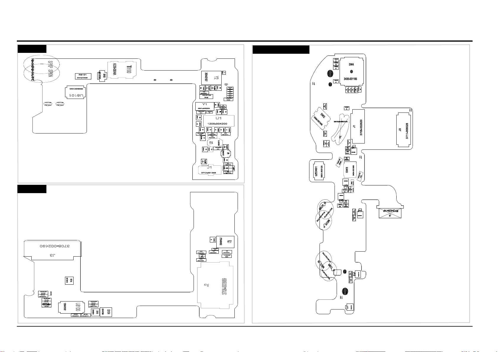
PCB diagrams
C1
2203-007165
C11
2203-006260
C14
2203-006260
C16
2203-003054
C17
2203-000995
C19
2203-005903
C21
2203-000995
C22
2203-003054
C23
2203-005903
C24
2203-005903
C26
2203-000995
C27
2203-006872
C3
2203-006423
C6
2203-006399
C7
2203-006423
C8
2203-006423
C9
2203-006399
CON_N
TP-C0_29-HZ
CON_P
TP-C0_29-HZ
D8100
0402-001991
DISCHARGE_N
QTP01000026
DISCHARGE_P
QTP01000026
F1
2909-001337
FB2
3301-001534
FB5
3301-001649
J1
3712-001348
L2
2703-002267L32703-001751
NR10
2007-000171
NR2
2007-000171
NR3
2007-000171
NR4
2007-000171
NR5
2007-000171
NR7
2007-000171
R10
OPEN-R1005
R11
OPEN-R1005
R12
OPEN-R1005
R13
OPEN-R1005
R14
OPEN-R1005
R15
OPEN-R1005
R2
2007-008483
R3
2007-008483
R4
2007-008483
R5
2007-008483
R6
2007-008483
R7
OPEN-R1005
R8
OPEN-R1005
R8101
2007-010026
R9
2007-008047
SPKN
TP
-
LW
-
OVAL
-
TYPE
SPKP
P
-
LW
-
OVAL
-
T8100
AD26-00044A
TP2
TP-C0_45PIE
U1
1205-004200
U2
1001-001715
U8101
0508-001243
Y1
2801-005054
Y2
2804-001937
1.2nH
C10
2203-006423
C12
2203-006260
C13
2203-006260
C2
2203-007165
C4
2203-006872
C5
2203-006872
C6104
2203-007269
C8100
OPEN-C1005
C8102
2203-002443
C8103
2203-005819
C8104
2203-000940
C8105
OPEN-C1005
C8106
2203-001153
FB1
3301-001895
J2
3708-002889
J3
3708-002490
L1
2703-004052
NR6
2007-000171
R1
2007-009876
R8100
2007-000173
R8102
2007-007766
R8103
2007-000138
R8104
2007-000109
R8105
2007-000148
U8100
1209-001901
2007-007009
C601
OPEN-R1005
D1
NC-UCLAMP0501T
D10
0406-001453
D2
NC-UCLAMP0501T
D3
NC-UCLAMP0501T
D4
NC-UCLAMP0501T
D5
NC-UCLAMP0501T
D6
NC-UCLAMP0501T
D8
0406-001375
D9
0406-001453
J1
3708-002620
J2
PAD-ZOOM5-WB750-2VER
J3
3711-006028
J4
FPCB-6284-14P
LED1
0601-002037
LED601
0601-003120
LED602
0601-002037
MICL_N
TP-LW-OVAL-TYPE
MICL_P
TP-LW-OVAL-TYPE
MICR_N
TP-LW-OVAL-TYPE
MICR_P
TP-LW-OVAL-TYPE
NR603
2007-000171
NR604
2007-000171
NR605
2007-000171
POLLIWOG1
INSICK060X100
POLLIWOG2
INSICK060X100
POLLIWOG3
INSICK060X100
POLLIWOG4
INSICK060X100
POLLIWOG5
NTH1_1
POLLIWOG6
NTH1_1
POLLIWOG7
NTH2_0
POLLIWOG8
NTH2_0
Q201
0501-002601
Q601
0501-002601
Q602
0501-002601
R1
2007-001306
R10
2007-008487
R11
2007-007671
R12
2007-001306
R13
2007-007138
R2
2007-007310
R210
2007-008294
R3
2007-007309R42007-007315R52007-007489
R6
2007-008269
R601
OPEN-R1005
R615
OPEN-R1005
R616
2007-001306
R617
OPEN-R1005
R7
2007-007488
R8
2007-007312
R9
2007-007315
SW2
3404-001349
SW3
3404-001360
SW4
3406-001185
U1
1209-001585
4-2 STROBE PCB 4-3 TOP FPCB
BOTTOM
4-2
TOP
TOP
Copyright© 1995-2012 SAMSUNG. All rights reserved.
Page 45
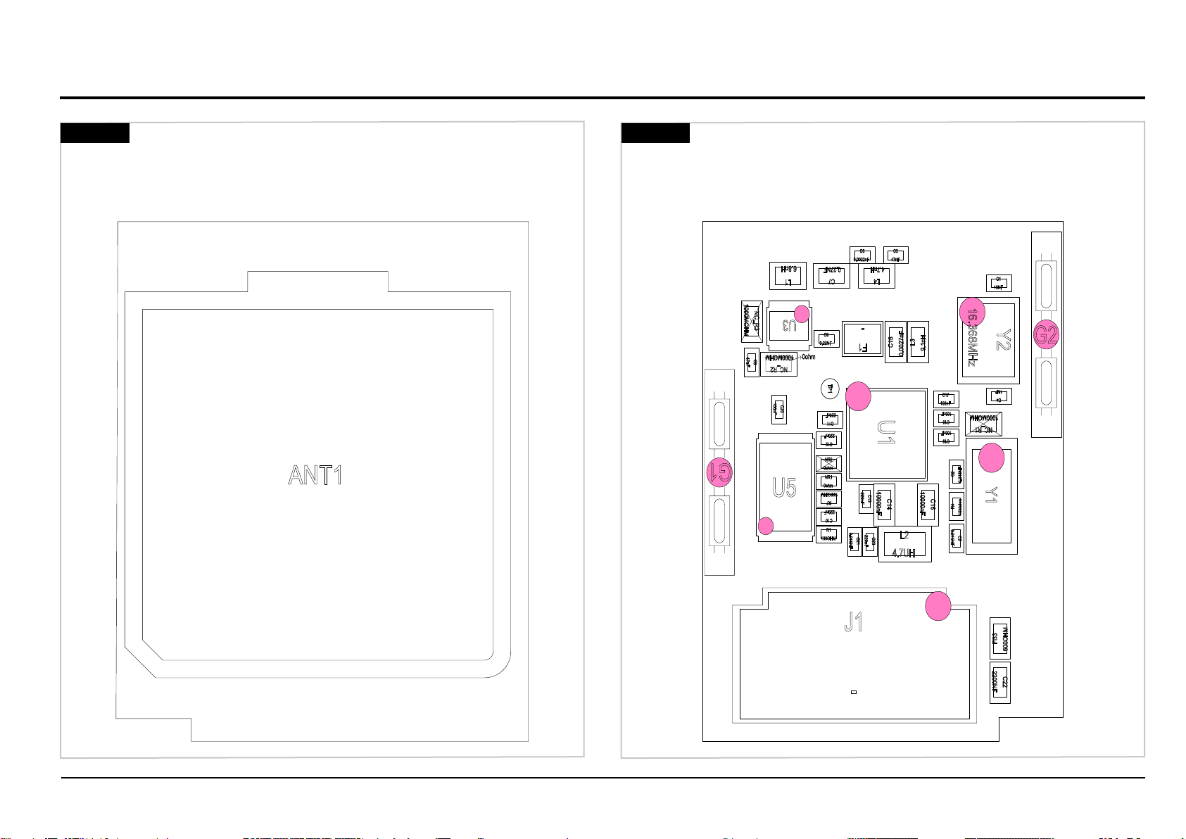
4-4 GPS PCB
C1
10NF
C10
220nF
C11
220nF
C12
220nF
C13
220nF
C14
10000nF
C15
0.0027nF
C16
10000nF
C17
100nF
C18
100nF
C19
100nF
C2
0.015NF
C20
100nF
C21
0.015NF
C22
2200NF
C23
220nF
C3
47nF
C4
1NF
C5
0.015NF
C6
0.0022nF
C7
0.27NF
C8
47nF
C9
0.22NF
F1
-
FB3
600OHM
G1
G2
J1
-
L1
6.8nH
L2
4.7UH
L3
9.1nH
L4
4.7nH
NC_R1
1000MOHM
NC_R2
1000MOHM
NC_R3
1000MOHM
NR1
0ohm
NR2
0ohm
R1
100OHM
R4
10Mohm
R7
100KOHM
TP1
U1
U3
U5
Y1
Y2
16.368MHz
0ohm
PCB diagrams
TOP
ANT1
BOTTOM
Copyright© 1995-2012 SAMSUNG. All rights reserved. 4-3
Page 46
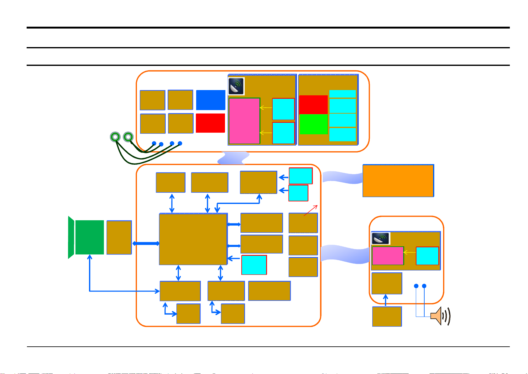
5. Block diagram
5-1 Block diagram
Zoom
Zoom
Lens
Lens
Module
Module
(x21)
(x21)
Stereo MICStereo MIC
IMX083
IMX083
16M
16M
(SONY)
(SONY)
Shutter
Shutter
KEY
KEY
MODE
MODE
DIAL
DIAL
72Mhz72Mhz
sLVDSsLVDS
SPISPI
TOP FPCTOP FPC
POWER
POWER
ZOOM
ZOOM
Compass
Compass
YAS530C
YAS530C
I2CI2C
SPI x2SPI x2
Motor/OIS Driver
Motor/OIS Driver
(R2J30511LG)
(R2J30511LG)
25Mhz25Mhz
Power LED
Power LED
KEY
KEY
KEY
KEY
(Blue)
(Blue)
AF LED
AF LED
(Orange)
(Orange)
Accelerometer
Accelerometer
(BMA222 )
(BMA222 )
SPISPI
DRIMeIII - POPDRIMeIII - POP
I2CI2C
x2
x2
MXL800SM
MXL800SM
I2CI2C
MUX + Charger
MUX + Charger
(MAX14616 )
(MAX14616 )
GPS PCBGPS PCB
1.5Ghz1.5Ghz
GPS IC
GPS IC
PMIC
PMIC
(ADP5046 )
(ADP5046 )
DDR2 2G x 2
DDR2 2G x 2
(MT47H128M16RT )
(MT47H128M16RT )
333Mhz333Mhz
ONE NAND 1G
ONE NAND 1G
(KFG1GN6W2D)
(KFG1GN6W2D)
XTAL
XTAL
(27MHz )
(27MHz )
Audio Amp
Audio Amp
(TPA2005D1ZQYR)
(TPA2005D1ZQYR)
XTAL
XTAL
(32KHz)
(32KHz)
TCXO
TCXO
(16MHz)
(16MHz)
CHG LED
CHG LED
(Red)
(Red)
Function
Function
LED
LED
(Green)
(Green)
Battery
Battery
SLB-10A
SLB-10A
XTAL
XTAL
(32KHz)
(32KHz)
SD card
SD card
Slot
Slot
HDMI JACK
HDMI JACK
(D type)
(D type)
JTAG
JTAG
Connector
Connector
KEY FPCB
KEY FPCB
(
NOBLE)
(NOBLE)
KEY ADKEY AD
WHEEL
WHEEL
KEY
KEY
SPEED
SPEED
KEY
KEY
PLAY
PLAY
KEY
KEY
pRGBpRGB
27Mhz27Mhz
SPISPI
Normal : 22Mhz
Normal : 22Mhz
High speed : 44Mhz
High speed : 44Mhz
WIFI FPCWIFI FPC
50Mhz50Mhz
AMOLED
AMOLED
( SMD / 3.0” / VGA)
( SMD / 3.0” / VGA)
2.4Ghz WLAN2.4Ghz WLAN
WIFI/STROBO PCBWIFI/STROBO PCB
WIFI BlockWIFI Block
WIFI IC
WIFI IC
BCM43362
BCM43362
STROBO
STROBO
BLOCK
BLOCK
XTAL
XTAL
(26MHz)
(26MHz)
Block diagram
SPISPI
Gyro
Gyro
(EWTS9P)
(EWTS9P)
uUSB
uUSB
JACK
JACK
MAIN PCBMAIN PCB
POPUP
POPUP
PCB
PCB
MONO SPKMONO SPK
Copyright© 1995-2012 SAMSUNG. All rights reserved. 5-1
Page 47
6. Firmware update
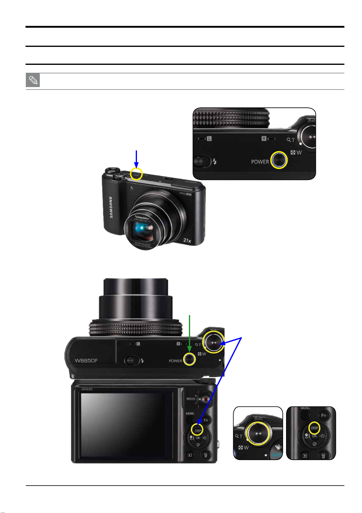
6-1 Product reset
■
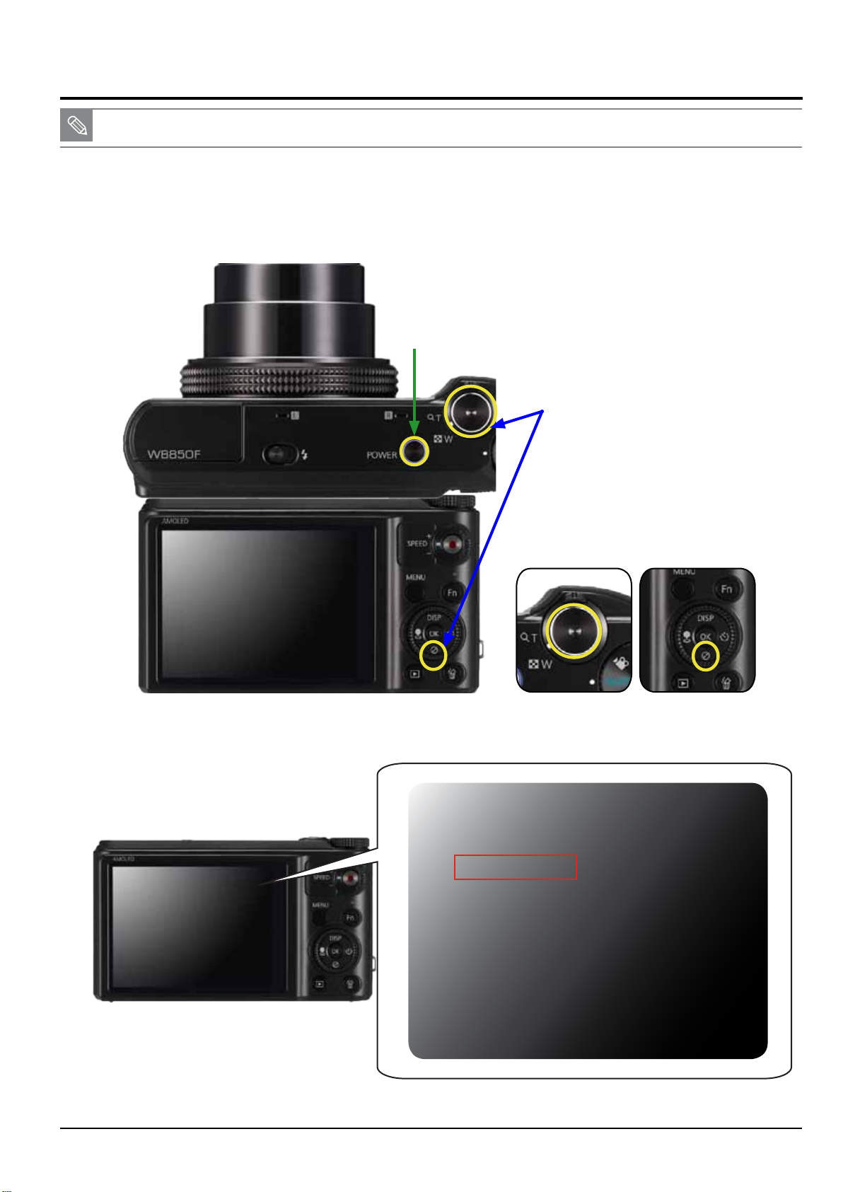
This section describes how to reset the camera.
1. Press the power button to turn on the camera.
q
Power button
Firmware update
Fig. 6-1
2. First half-press and hold the shutter button and up button, and then press the power button.
e
Power button
w
Shutter button + up button
Up buttonShutter button
Copyright© 1995-2012 SAMSUNG. All rights reserved.
6-1
Fig. 6-2
Page 48
Firmware update
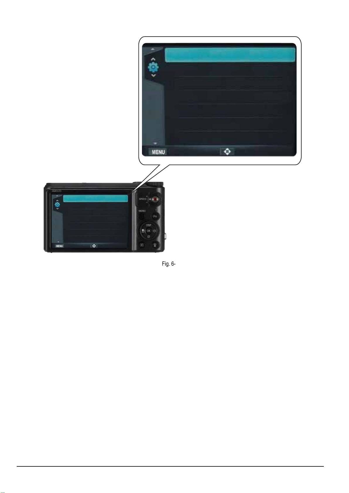
3. Turn the camera on to view the reset setting.
Language English >
Time Zone London >
Date/Time Set 01/01/2012 >>
Date Type MM/DD/YYYY >
Language English >
Time Zone London >
Date/Time Set 01/01/2012 >>
Date Type MM/DD/YYYY >
MoveExit
Exit
Fig. 6-3
Move
6-2
Copyright© 1995-2012 SAMSUNG. All rights reserved.
Page 49
6-2 Version check
■
This section describes how to view the current rmware version.
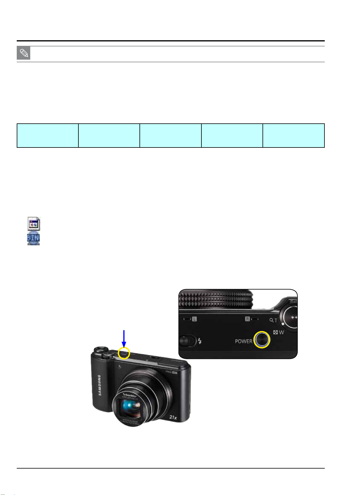
1. Before upgrading your camera’s rmware, make sure the battery is fully charged.
2. Turn off the power of the camera.
3. First press and hold the shutter button and down button, and then press the power button.
w
Power button
Firmware update
q
Shutter button + down button
Fig. 6-4
4. The current rmware version is displayed on the LCD screen. Then, turn the camera off.
DSC: G202090
FW Version
DSC: G202090
OIS : 1201101
S/N : 123456789123
OIS : 1201101
S/N : A0013CBH700369C
down buttonShutter button
FW Version
Copyright© 1995-2012 SAMSUNG. All rights reserved.
6-3
Fig. 6-5
Page 50
Firmware update
6-3 Upgrade
■
This section describes how to upgrade the rmware.
♦
Firmware execution information
The below table provides the information of rmware structure.
Code section contains the execution code to operate the camera. The partition 1 to 3 sections contain the all the resources to operate the
camera. Partition 3 section contains the defective pixel adjustment data and lens shading adjustment data.
User Area contains the setting value when user sets up the setting by the menu button. Also, User Area section contains the adjustment
data through the adjustment process.
Code partition1 partition2 partition3 User Area
<Table 6-1>
►
Reference for general version:
- It updates data contained in the Code and partition 1 section while partition 3 and User Area section data remain.
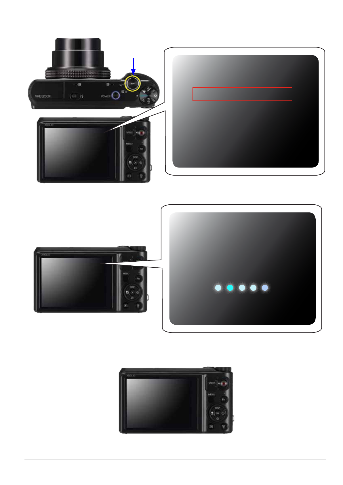
1. Format the memory card and copy the two les such as FWUP and WB850-FW-PV-202083.bin into the memory card.
Then insert the memory card into the camera.
* When the rmware is upgraded, all the camera settings are set to their default values. Since all the les stored in the
internal memory will be deleted, ensure that les are copied to other storage devices before upgrading rmware.
FWUP
WB850-FW-PV-202083.bin
2. It is recommended that you use an AC adaptor or the fully charged batteries.
* Before upgrading your camera’s rmware, make sure the battery is fully charged.
3. Press the power button to turn on the camera.
Power button
6-4
Fig. 6-6
Copyright© 1995-2012 SAMSUNG. All rights reserved.
Page 51
Firmware update
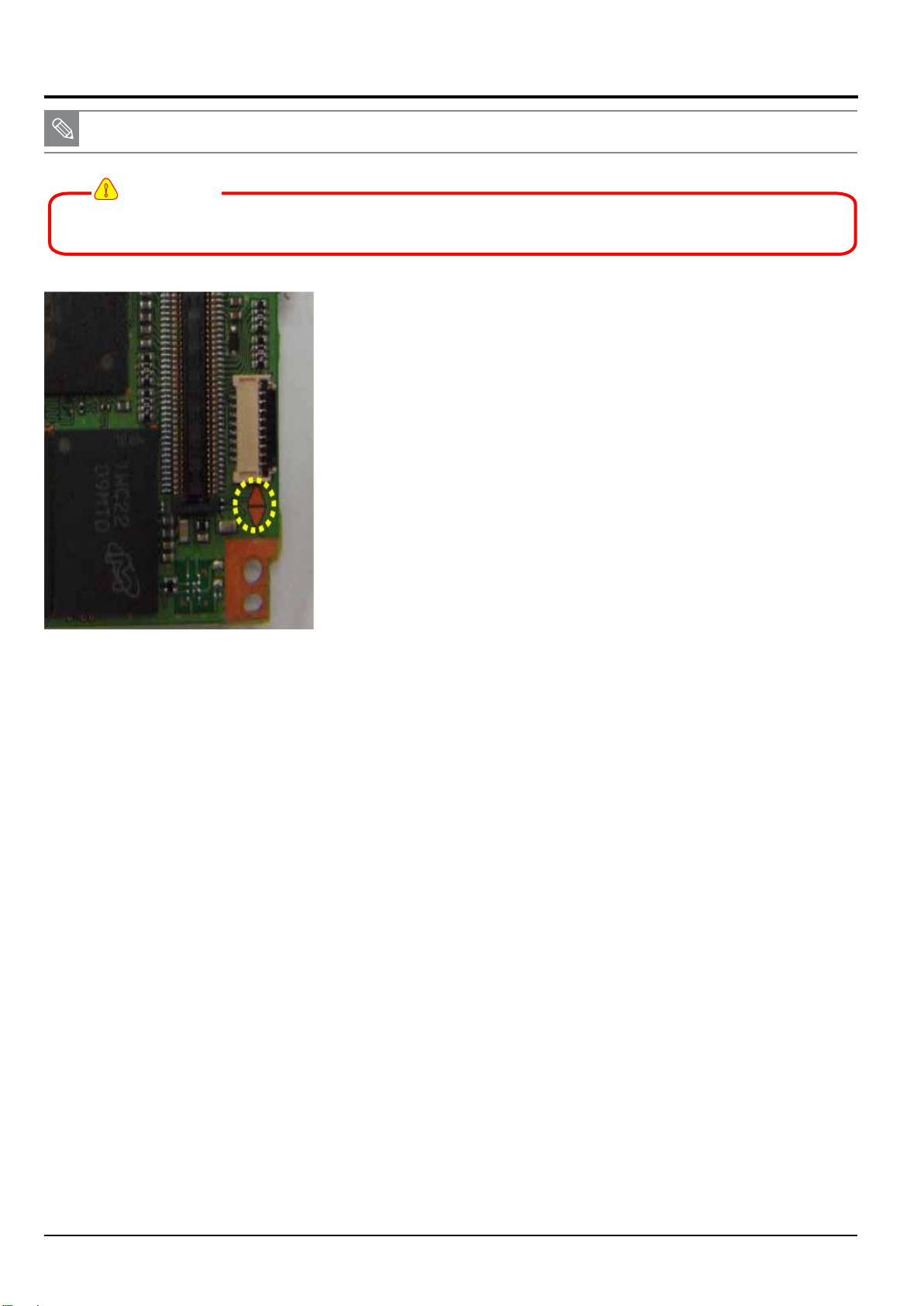
4. The rmware version will display on the LCD screen. Press and hold the shutter button to start the rmware upgrade process.
Shutter button
FW Version
DSC: Full G202090 -> G202083
OIS : 1201101
S/N : A0013CBH700369C
FW Version
DSC: G202090
OIS : 1201101
S/N : 123456789123
Press the shutter button to upgrade the firmware.
Press the shutter button to upgrade the firmware.
Fig. 6-7
5. The display will show “Firmware is updating...”
Do not power off during the process.
Firmware is updating...
Do not power off during the process.
Fig. 6-8
6. Once the rmware upgrade is complete, the camera will automatically power off.
Firmware is updating...
Copyright© 1995-2012 SAMSUNG. All rights reserved.
6-5
Fig. 6-9
Page 52
Firmware update
6-4 How to update the fimware when forced to quit
■
This section describes how to update the rmware when the power is not turned on.
!
CAUTION
All of the adjustment data will be deleted when forced to quit.
Therefore you have to go over the adjustment process all over again.
1. Solder the Boot option TP on Main PCB to short out the circuit.
2. Download the rmware le.
(WB850_DSP_G_SR_SXXXXXX.zip)
3. Unzip the rmware le downloaded and copy the three rmware les below to the SD card.
(dnloader.bin, up_wb850.bin, WB850-FW-XX-XXXXXX.bin)
4. Insert the SD card containing the three rmware les into the SD card slot.
Press the power button to turn on the camera.
5. LED will blink while the rmware update is processing.
LED will stop blinking when the rmware update is completed.
6. Remove the solder the Boot option TP on Main PCB.
Then press the power button to turn on the camera.
6-6
Copyright© 1995-2012 SAMSUNG. All rights reserved.
Page 53
7. Adjustment
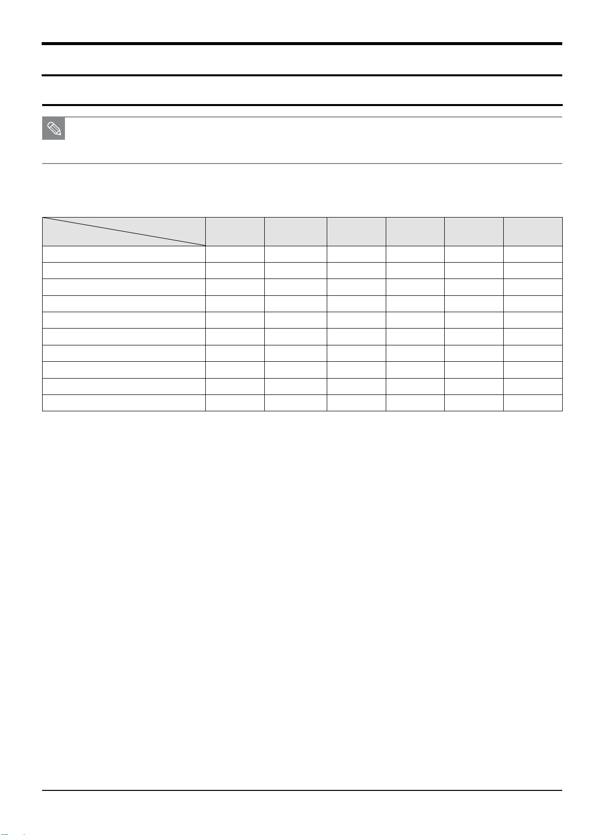
7-1 Basic guide for adjustment
■ After replacing the parts, you need to adjust the following items.
■ The table below provides information about the necessary adjustment process.
Adjustment
1. Please refer to the table information before beginning the adjustment process.
MAIN
PCB
FIRMWARE UPGRADE
LENS SHADING ADJ
SHUTTER CLOSE TIME ADJ
IRIS ADJ
CMOS GAIN ADJ
FLASH & AWB ADJ
PUNT ADJ
CMOS DEFECT PIXEL ADJ
OIS CENTERING
SERIAL NUMBER WRITING ADJ
2. Necessary equipment
1) AE TESTER: AE TESTER is used to adjust the luminance level and the color temperature of the Light box.
It helps adjust the luminance level to 12 LV and color temperature of the Light box to 3300K.
2) Innity Collimator for PUNT adjustment
3) 18% Reectance gray chart for FLASH & AWB adjustment and Dark Box.
4) POWER SUPPLY: 4.2V/2A
O X X X X X
O X X X O O
O X X X O O
O X X X O O
O X X X O O
O O X O O O
O X X X O O
O X X X O O
O X X X O O
O X X X X X
WIFI-STROBO
PCB
<Table 7-1>
TOP
FPCB
POP UP PCB
CIS
PCB
BARREL
ASSY
3. Adjustment le
It is necessary to copy the adjustment le such as “WB850_ADJ.TXT” into the memory card to proceed the process.
Copyright© 1995-2012 SAMSUNG. All rights reserved.
7-1
Page 54
Adjustment
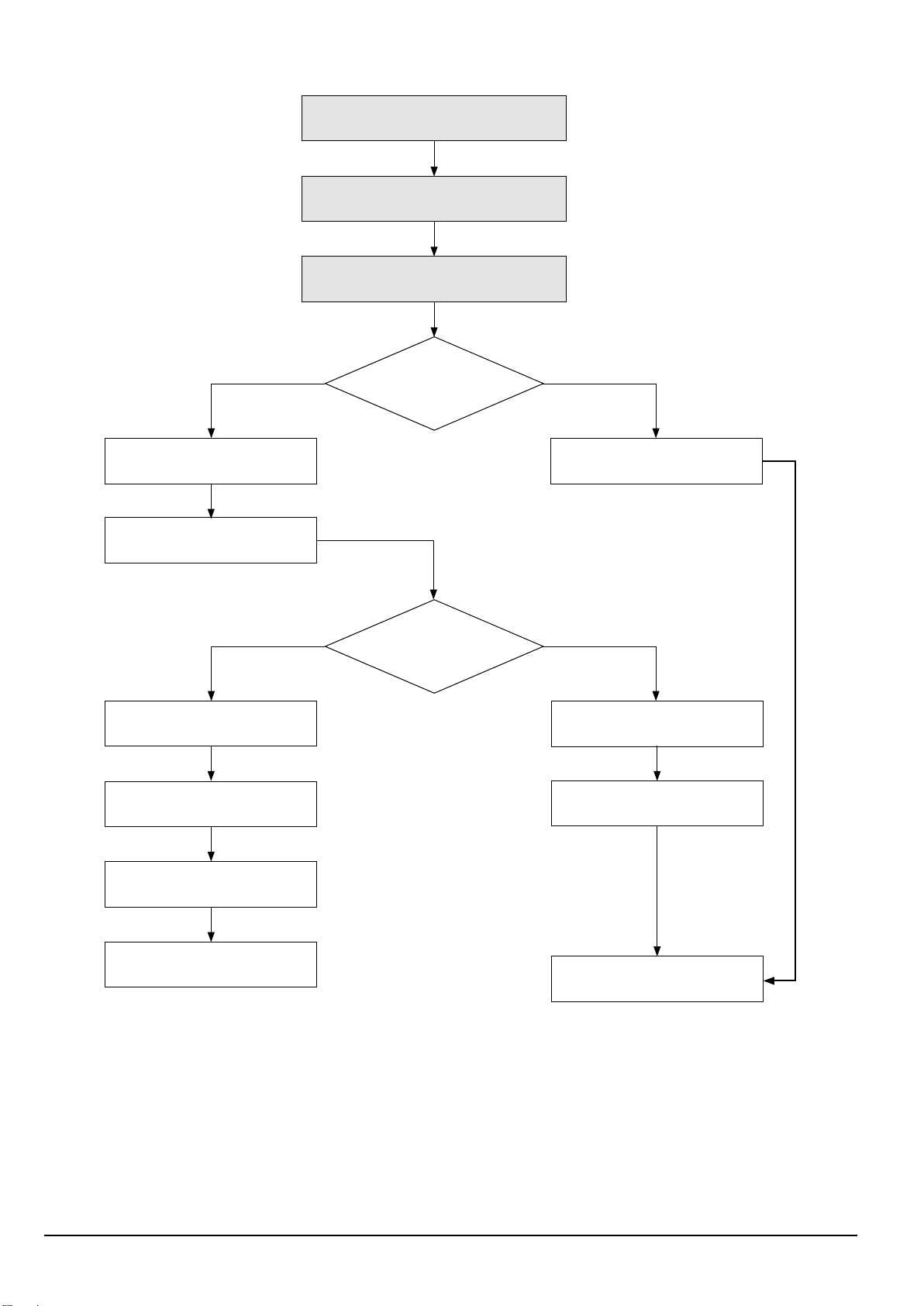
4. Stages of the adjustment process is described below.
Insert Flash Card (Memory card)
by process
Power On (Worker)
Auto process to Test Mode/Execute
adjustment script
Yes
Check by process
Record log le by process
(If necessary)
Yes
Save adjustment value to EEPROM
Display adjusted value and whether
it is OK (LCD)
Check process ID
Pass/No pass
No
Display last process
ID executed normally
No
Save adjustment value to
EEPROM (If necessary)
Display adjusted value and whether
it is OK (LCD)
7-2
Set process ID (EEPROM)
Auto Power Off or continue
to proceed process
Power Off or stand by
<Table 7-2>
Copyright© 1995-2012 SAMSUNG. All rights reserved.
Page 55
7-2 Lens shading
■ This section describes how to adjust the Lens shading.
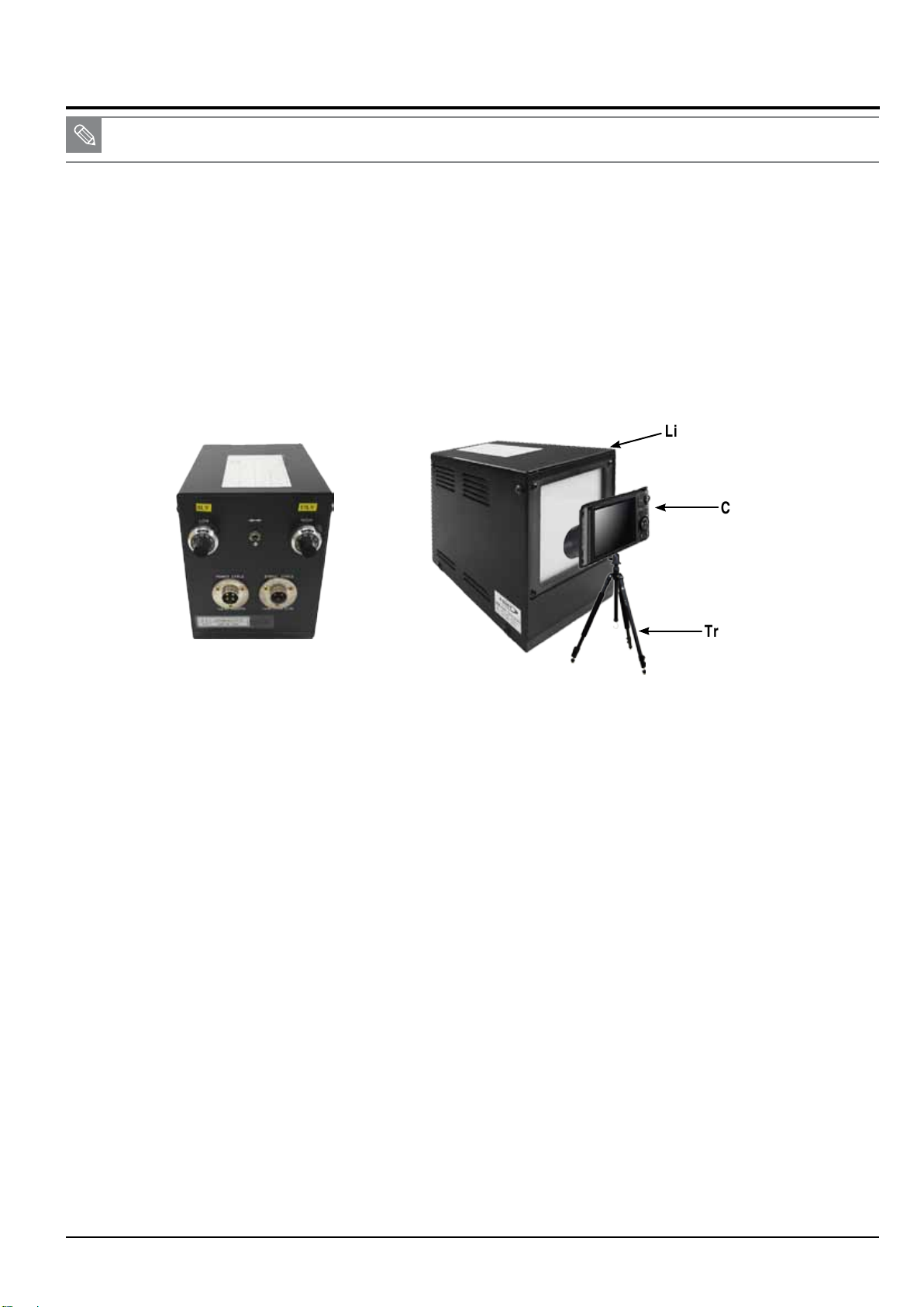
< Adjustment method >
NOTE: AE TESTER is used to adjust the luminance level and the color temperature of the Light box.
AE TESTER helps adjust the luminance level of the Light box to 12 LV and color temperature of the Light box to 3300K.
Please follow the instruction to begin the process.
1. Copy the “WB850_ADJ.TXT” le into the memory card and insert it into the camera.
2. Mount the camera on AE TESTER. Press the power button to open the lens tube.
Set the distance between the rear of the lens tube and the light box to 10mm ± 1mm.
3. Set the luminance level of the AE TESTER to 12 LV.
Light source box
Adjustment
Camera
Tripod
Back view of light source box
Fig. 7-1
4. Once the camera is turned on by pressing the power button, the process will begin automatically.
1) The iris and zoom is set to zero.
2) Refer to the EEPROM WRITE information and write the adjustment value to EEPROM.
3) Refer to the CARD WRITE information and write the adjustment value to the data le.
4) Set the USL(Upper Specication Limit) and LSL(Lower Specication Limit).
5. Once the process is completed, the camera will automatically turn off.
< Adjustment result >
Double-click the memory card folder to view the result. You will find the generated CSV file in the folder. Click the file to check the generated
content.
< Restriction >
If the CSV le size is more than 30KB, delete all of the previous data and repeat the step 4.
Copyright© 1995-2012 SAMSUNG. All rights reserved.
7-3
Page 56
Adjustment
7-3 Shutter close time ADJ
■ This section describes how to adjust Shutter close time.
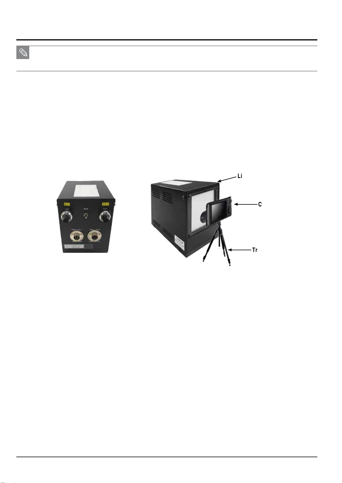
■ It generates the relative tolerance. This adjustment process help reduce the tolerances for better performance.
■ It proceeds CCD Gain adjustment process simultaneously.
< Adjustment method >
NOTE: AE TESTER is used to adjust the luminance level and the color temperature of the Light box.
AE TESTER helps adjust the luminance level of the Light box to 12 LV and color temperature of the Light box to 3300K.
Please follow the instruction to begin the process.
1. Copy the “WB850_ADJ.TXT” le into the memory card and insert it into the camera.
2. Mount the camera on AE TESTER. Press the power button to open the lens.
Set the distance between the rear of the lens and the light box to 10mm ± 1mm.
3. Set the luminance level of the AE TESTER to 12 LV.
Light source box
Camera
Tripod
Back view of light source box
Fig. 7-2
4. Once the camera is turned on by pressing the power button, the process will begin automatically.
1) The Line delay and SUb delay are adjusted to the luminance level range of 12 LV.
2) If the value of the Line delay is in the range of the minimum and maximum value, the result is OK. Otherwise, it is NG.
3) Refer to the EEPROM WRITE information and write the adjustment value to EEPROM.
4) Refer to the CARD WRITE information and write the adjustment value to the data le.
5. Once the process is completed, the camera will automatically turn off.
< Adjustment result >
Double-click the memory card folder to view the result. You will find the generated CSV file in the folder. Click the file to check the generated
content.
< Restriction >
If the CSV le size is more than 30KB, delete all of the previous data and repeat the step 4.
7-4
Copyright© 1995-2012 SAMSUNG. All rights reserved.
Page 57
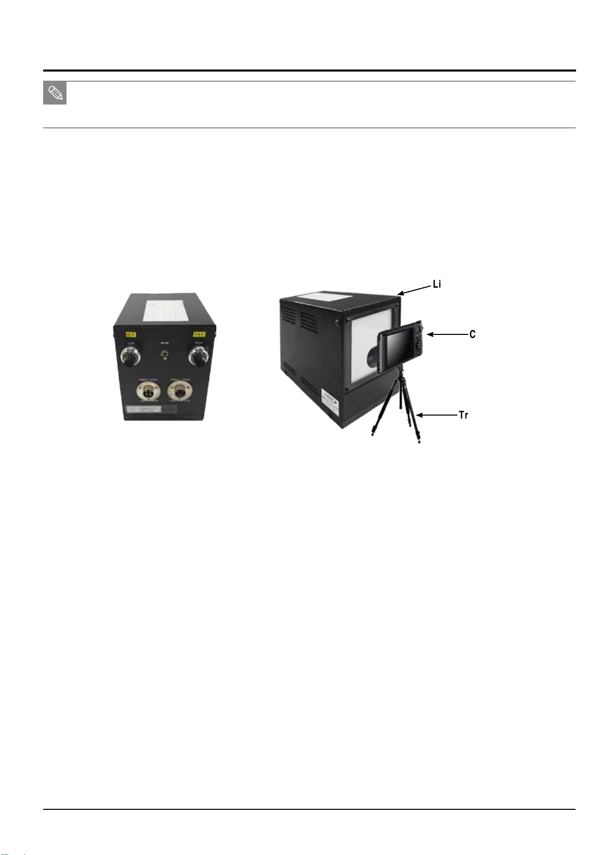
7-4 IRIS ADJ
■ This section describes how to adjust Iris.
■ It generates the relative aperture tolerance. This adjustment process help reduce the aperture tolerances for better performance.
< Adjustment method >
NOTE: AE TESTER is used to adjust the luminance level and the color temperature of the Light box.
AE TESTER helps adjust the luminance level of the Light box to 12 LV and color temperature of the Light box to 3300K.
Please follow the instruction to begin the process.
1. Copy the “WB850_ADJ.TXT” le into the memory card and insert it into the camera.
2. Mount the camera on AE TESTER. Press the power button to open the lens.
Set the distance between the rear of the lens and the light box to 10mm ± 1mm.
3. Set the luminance level of the AE TESTER to 12 LV.
Light source box
Adjustment
Camera
Tripod
Back view of light source box
Fig. 7-3
4. Once the camera is turned on by pressing the power button, the process will begin automatically.
1) Set the optical aperture value (AV).
2) Set the Exposure Time and Gain Value to xed values. Get the Preview G value by changing the aperture level.
3) If the Preview G value in the higher aperture level is greater than the Preview G value in the lower aperture level, luminance level is 12 LV.
Otherwise, luminance level is not 12 LV.
4) Check the aperture value (AV) generated if it is in the range of the Iris adjustment.
If the value is in the range, the color temperature of the Light box is 3300K. Otherwise, color temperature of the Light box is not 3300K.
5) Set the nal aperture value (AV) as the difference between the highest and the lowest aperture value if it generates the value fulllled
the step 3 to 4.
6) Refer to the EEPROM WRITE information and write the adjustment value to EEPROM.
7) Refer to the CARD WRITE information and write the adjustment value to the data le.
5. Once the process is completed, the camera will automatically turn off.
< Adjustment result >
Double-click the memory card folder to view the result. You will find the generated CSV file in the folder. Click the file to check the generated
content.
< Restriction >
If the CSV le size is more than 30KB, delete all of the previous data and repeat the step 4.
Copyright© 1995-2012 SAMSUNG. All rights reserved.
7-5
Page 58
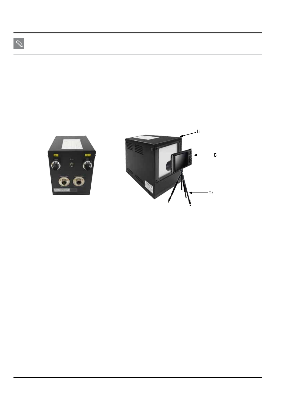
Adjustment
7-5 CMOS gain ADJ
■ This section describes how to adjust CMOS gain.
■ It generates the relative CMOS saturation tolerance.
This adjustment process help reduce the CMOS saturation tolerances for better performance.
< Adjustment method >
NOTE: AE TESTER is used to adjust the luminance level and the color temperature of the Light box.
AE TESTER helps adjust the luminance level of the Light box to 12 LV and color temperature of the Light box to 3300K.
Please follow the instruction to begin the process.
1. Copy the “WB850_ADJ.TXT” le into the memory card and insert it into the camera.
2. Mount the camera on AE TESTER. Press the power button to open the lens.
Set the distance between the rear of the lens and the light box to 10mm ± 1mm.
3. Set the luminance level of the AE TESTER to 12 LV.
Light source box
Camera
Tripod
Back view of light source box
Fig. 7-4
4. Once the camera is turned on by pressing the power button, the process will begin automatically.
1) Refer to the EEPROM WRITE information and write the adjustment value to EEPROM.
2) Refer to the CARD WRITE information and write the adjustment value to the data le.
3) Set the USL(Upper Specication Limit) and LSL(Lower Specication Limit).
5. Once the process is completed, the camera will automatically turn off.
< Adjustment result >
Double-click the memory card folder to view the result. You will find the generated CSV file in the folder. Click the file to check the generated
content.
< Restriction >
If the CSV le size is more than 30KB, delete all of the previous data and repeat the step 4.
7-6
Copyright© 1995-2012 SAMSUNG. All rights reserved.
Page 59
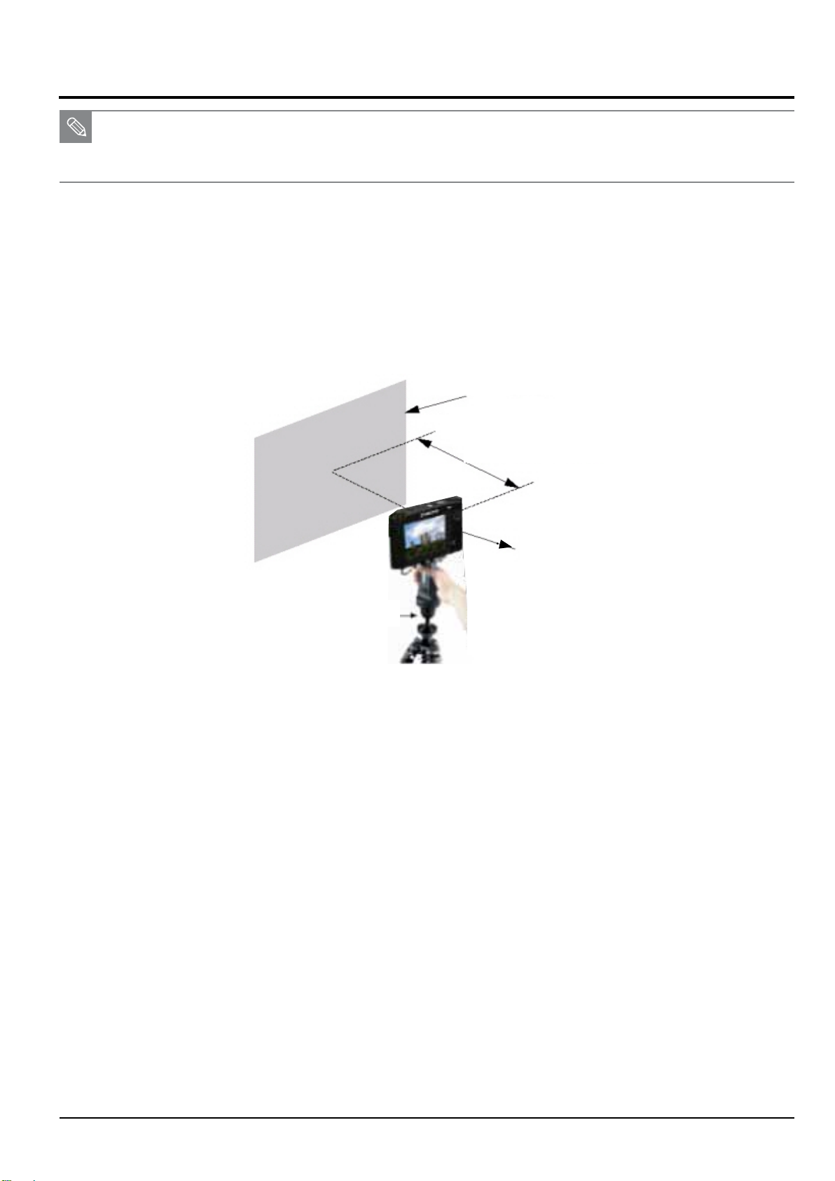
7-6 Flash & AWB ADJ
■ This section describes how to adjust the Flash and AWB.
It test the brightness of Strobe within the certain limit of the luminance level to verify that a product works properly.
■ It proceeds the AWB HIGH adjustment process simultaneously.
<Adjustment method>
1. Set the 18% Reflectance gray card on the wall in the darkroom.
2. Copy the “WB850_ADJ.TXT” le into the memory card and insert it into the camera. Mount the camera on Dark Box.
3. Set the distance between the reflective paper and camera to 50cm.
18% Reflectance gray card
Adjustment
50cm
Camera
Tripod
Fig. 7-5
4. Once the camera is turned on by pressing the power button, the process will begin automatically.
1) Refer to the Table 7-2. It provides the information of the adjustment process.
Proceed the process twice in a raw. If the value is the range of the standard luminance level, it assures overall hardware
quality is good.
2) Average out the two test values. Then check the R gain and B gain to verify the quality of hardware.
3) Refer to the EEPROM WRITE information and write the adjustment value to EEPROM.
4) Write the R. B gain to the EEPROM if the hadware quality test is passed sucessfully.
5. Once the process is completed, the camera will automatically turn off.
< Adjustment result >
Double-click the memory card folder to view the result. You will find the generated CSV file in the folder. Click the file to check the generated
content.
< Restriction >
If the CSV le size is more than 30KB, delete all of the previous data and repeat the step 4.
Copyright© 1995-2012 SAMSUNG. All rights reserved.
7-7
Page 60
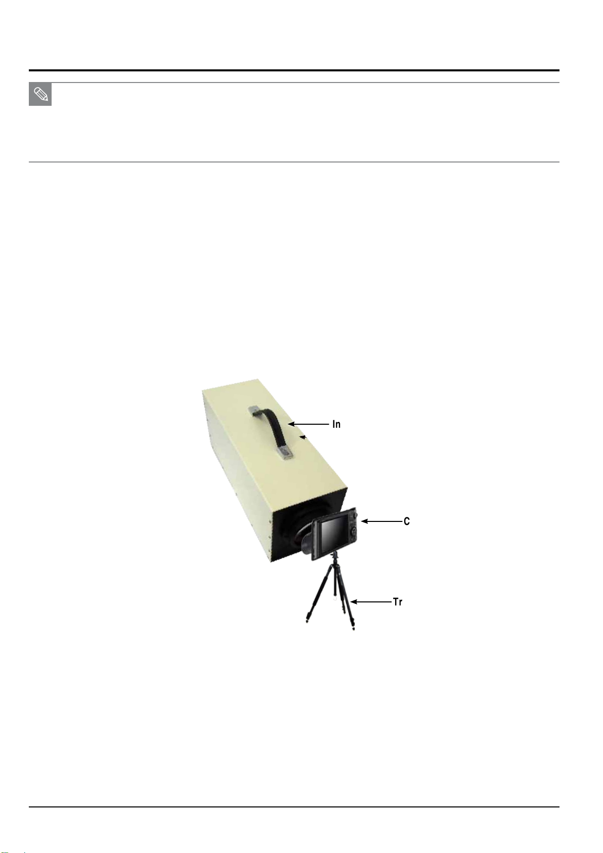
Adjustment
7-7 Punt ADJ
■ This section describes how to adjust the PUNT. After replacing the MAIN PCB and BARREL, you must decide the AF search range,
allowing focus to be properly adjusted for the best picture quality.
■ Necessary equipment: Innity Collimator/ Innity Subject
(Proceed through the adjustment process with Innity Collimator or Innity Subject as illustrated below.)
< With Innity Collimator >
1. Copy the “WB850_ADJ.TXT” le into the memory card and insert it into the camera.
2. Please follow the instruction below to begin the punt adjustment process.
1) Innity Collimator Specications
- Set the luminance level to 6 LV.
- Set the distance as less than 1cm between the end of camcorder lens and lens surface of the innity Collimator.
- Do not remove the camcorder from tripod during the process.
Fig. 7-6
Infinity Collimator
Camera
Tripod
7-8
Copyright© 1995-2012 SAMSUNG. All rights reserved.
Page 61
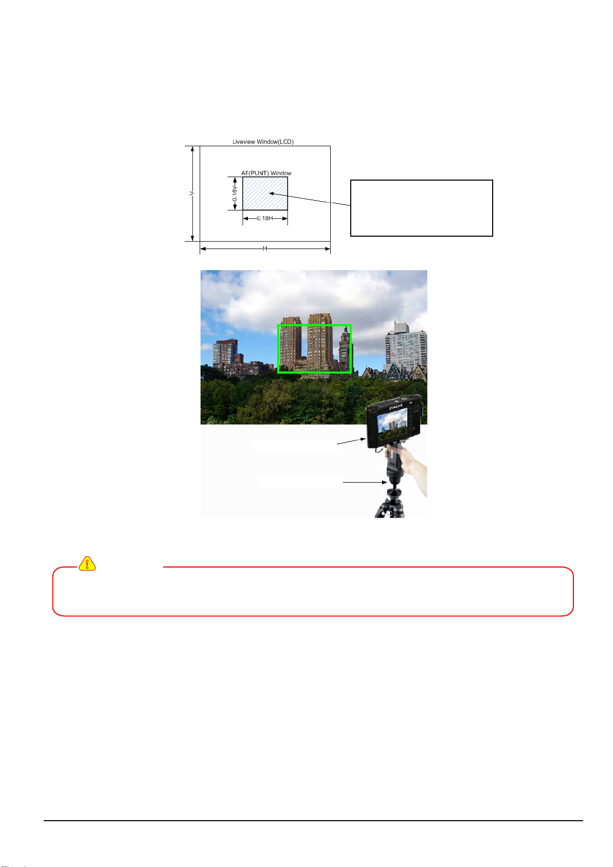
< With Subject Specications >
2) Innity Subject Specications
- Secure the camcorder on the tripod and adjust the height.
- Focus on a subject at innity which is more than 500m away.
- Choose a subject where it is essentially innitely far away such as apartment or church as illustrated below.
Set the subject centered and an
subject should enough be dis-
played within about 1/5(one-fth)
of the LCD screen size.
Adjustment
Camera
Tripod
Fig. 7-7
!
CAUTION
Try not to attempt the adjustment process during the night. It may generate the inaccurate test result
due to the difculty of auto focus. If you want to proceed the process, choose a subject such as glass building
making the contrast level low.
3. Press the power button to turn on the camera.
4. The adjustment process will automatically begin.
<Adjustment result>
Double-click the memory card folder to view the result. You will find the generated CSV file in the folder. Click the file to check the generated
content.
Copyright© 1995-2012 SAMSUNG. All rights reserved.
7-9
Page 62
Adjustment
7-8 CMOS defect ADJ
■ This section describes how to adjust the defective pixel detection for CMOS image sensor.
<Adjustment method>
1. Copy the “WB850_ADJ.TXT” le into the memory card and insert it into the camera.
2. Once the camera is turned on by pressing the power button, the process will begin automatically.
1) Check the data such as reference level, exposure time and loop before beginning the defective pixel detection adjustment.
2) Refer to the specications about the maximum number of defective cells. Then proceed the process.
3) Refer to the CARD WRITE information and write the number of defective cells to the data le.
3. Once the adjustment process is completed, the camera will automatically turn off.
<Adjustment result>
Double-click the memory card folder to view the result. You will find the generated CSV file in the folder. Click the file to check the generated
content.
7-9 OIS centering ADJ
■ This section describes how to test the OIS centering performance.
<Adjustment method>
1. Copy the “WB850_ADJ.TXT” le into the memory card and insert it into the camera.
2. Once the camera is turned on by pressing the power button, the process will begin automatically.
OIS module is actively moved up, down, left and right .
3. Once the adjustment process is completed, the camera will automatically turn off.
<Adjustment result>
Double-click the memory card folder to view the result. You will find the generated CSV file in the folder. Click the file to check the generated
content.
!
CAUTION
Set the camera face up on a stable surface such as a table, desk or oor.
Otherwise, it will signicantly degrade the performance, generating the noise on Gyro Sensor and Hall Sensor.
7-10
Copyright© 1995-2012 SAMSUNG. All rights reserved.
Page 63
Adjustment
7-10 Serial number writing process
■ Serial number is provided in the cameras non-volatile memory.
A serial number is a 15-digit alphanumeric code indicated on the sticker at the bottom of a camera.
■ It helps to verity the authenticity of Samsung digital camera by checking the 15-digit serial number.
!
CAUTION
It is necessary to proceed the serial number writing process after replacing the parts due to the Main PCB failure.
<Process method>
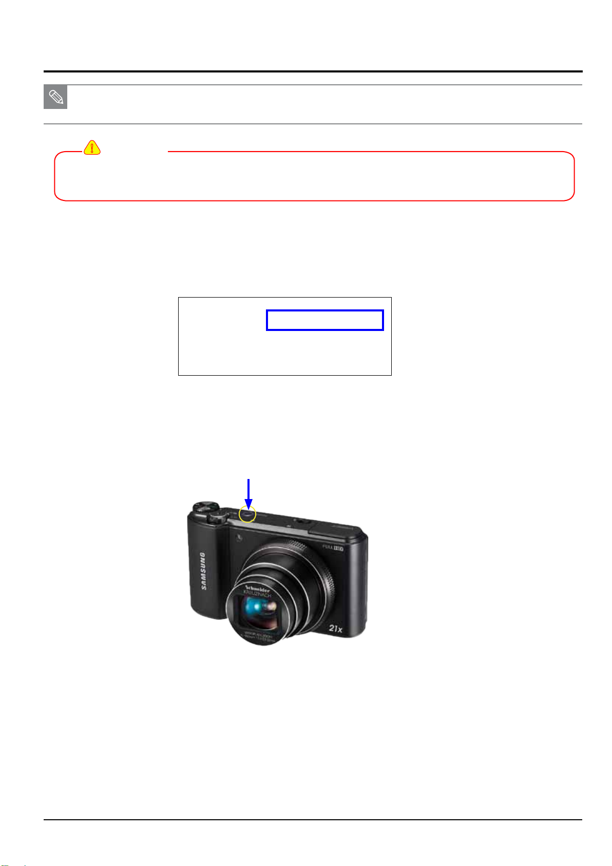
1
.
Generate WB850_ADJ.txt le and copy it into the memory card.
• Find the 15-digit alphanumericserial number written on the Main board.
sys_serial set
A0013CBH700369C
sys_serial get
poweroff zoom_close
Fig. 7-8
2. Replace the Main board and insert the memory card that contains WB850_ADJ.txt le into the camera.
3. Press the power button to turn on the camera.
Power button
Fig. 7-9
4. The new serial number will be applied automatically and it is provided in the cameras non-volatile memory.
5. Once the process is completed, the camera will automatically turn off.
Copyright© 1995-2012 SAMSUNG. All rights reserved.
7-11
Page 64
Adjustment
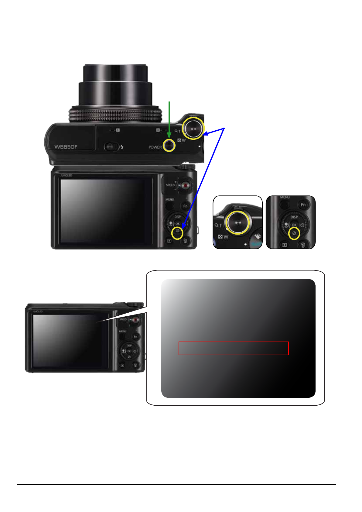
<Process result>
To view the result, rst press and hold the shutter button and down button, and then press the power button.
Serial number will be displayed on the screen.
w
Power button
q
Shutter button + down button
down buttonShutter button
FW Version
DSC: G202090
OIS : 1201101
S/N : 123456789123
FW Version
FW Version
DSC: G202090
OIS : 1201101
S/N : A0014CBH700369C
Fig. 7-10
7-12
Copyright© 1995-2012 SAMSUNG. All rights reserved.
Page 65
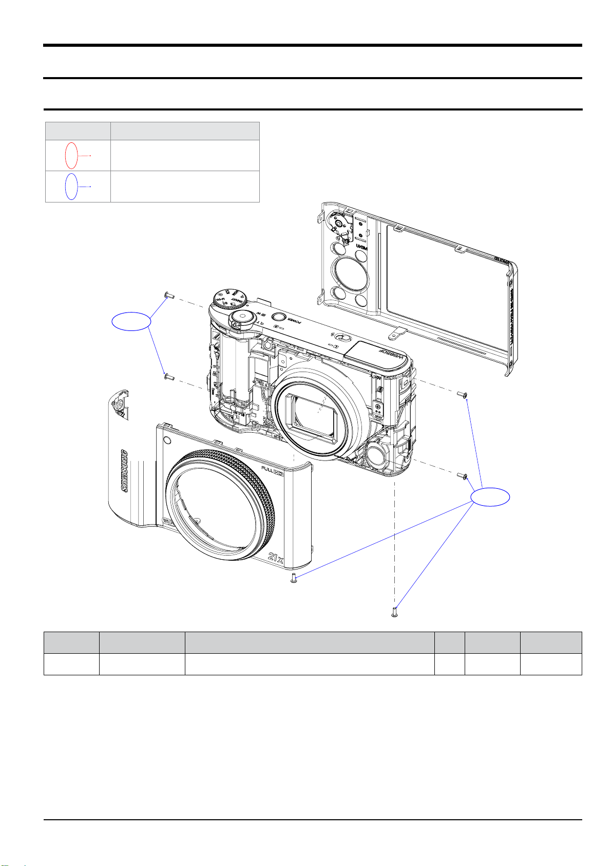
8. Exploded view and parts list
8-1 BODY ASSEMBLY
Exploded view and parts list
Item
Service Info.
Service is available. (SA)
Service is not available. (SNA)
1-1
1-1
Loc. No. Parts No. Description Qty Available Remark
1-1 6001-002152 SCREW(MACHINE) 6 X
Copyrightⓒ 1995-2012 SAMSUNG. All rights reserved.
8-1
Page 66
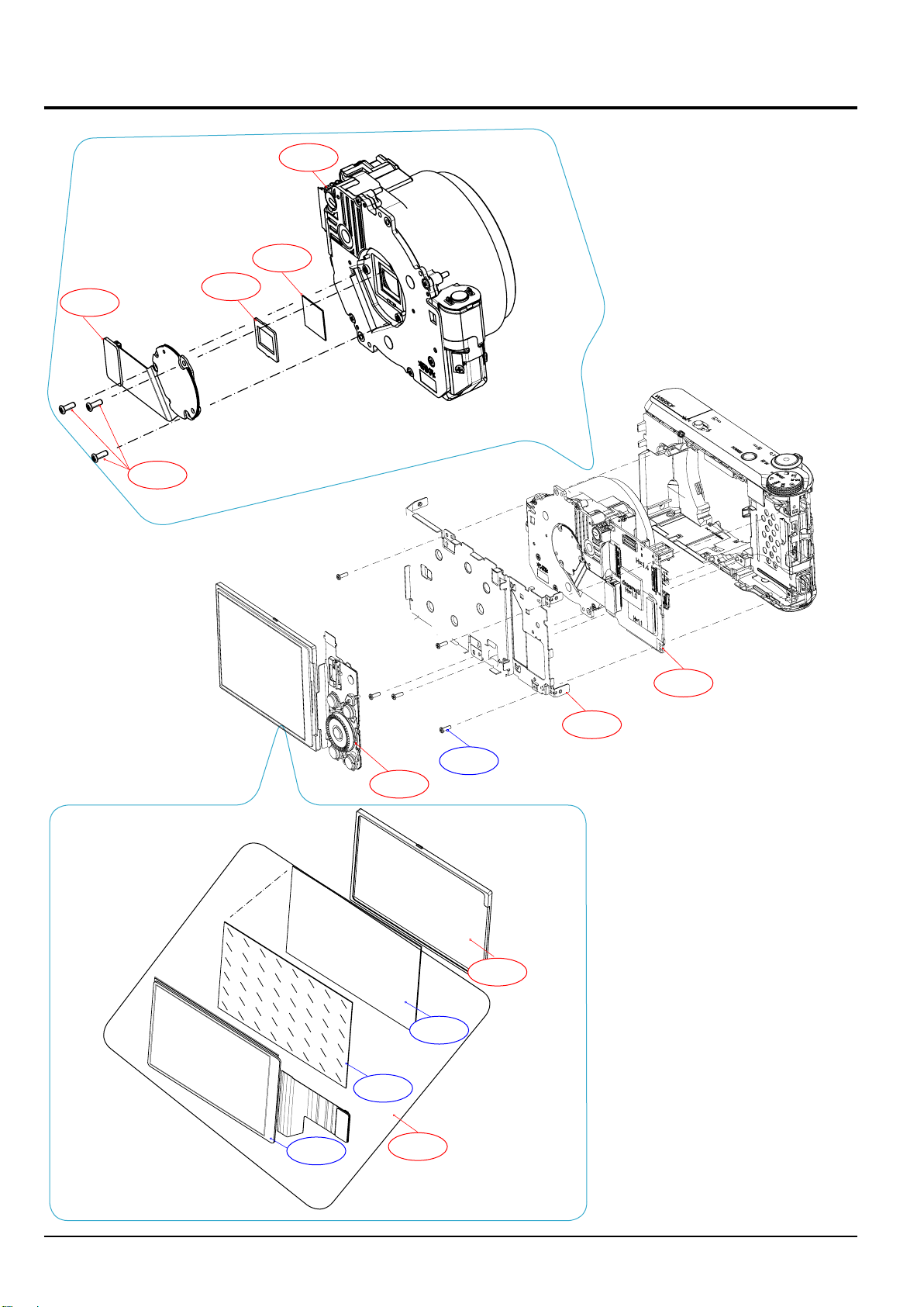
Exploded view and parts list
8-2 MAIN ASSEMBLY
2-7
2-8
2-9
2-5
2-6
2-4
2-11
2-1
2-2
2-3
2-13
2-12
8-2
2-10
2-14
Copyrightⓒ 1995-2012 SAMSUNG. All rights reserved.
Page 67
Exploded view and parts list
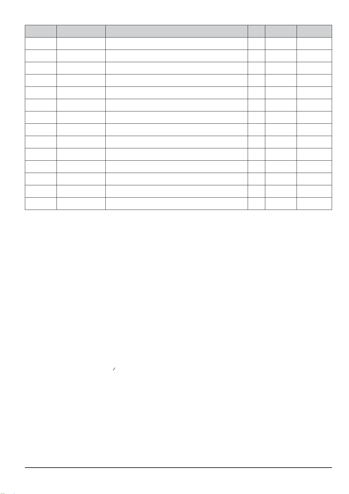
Loc. No. Parts No. Description Qty Available Remark
2-1 AD92-01807A
2-2 AD97-22137A ASSY-FRAME MAIN 1 O
2-3 6003-001717 SCREW(TAPTITE) 5 X
2-4 AD92-01867A ASSY-PCB KEY 1 O
2-5 AD97-21773A ASSY BARREL-WB850 1 O
2-6 AD63-06992A CUSHION GLASS-IR CUT FILTER 1 O
2-7 AD63-06759A SHEET-FILTER-WB850 1 O
2-8 AD92-01802A ASSY PCB FPC-CIS;DSC 1 O
2-9 6003-001633 SCREW-TAPTYPE 3 O
2-10 AD97-22506A OELD AM 1 X
2-11 AD63-06840A CUSHION-AMOLED 1 X
2-12 AD61-05677A PLATE-AMOLED 1 X
2-13 AD67-02470A RUBBER-AMOLED 1 O
2-14 AD97-22506A LCD SUB ASSY 1 O
ASSY-PCB MAIN
1 O
Copyrightⓒ 1995-2012 SAMSUNG. All rights reserved.
8-3
Page 68
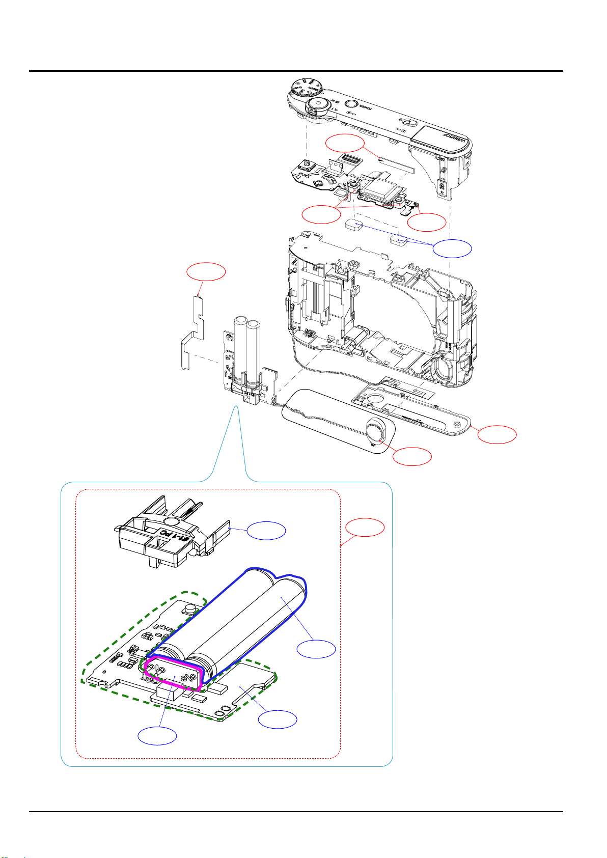
Exploded view and parts list
8-3 MAIN SUB ASSEMBLY
3-5
3-3
3-6
3-1
3-4
3-2
3-7
8-4
3-11
3-9
3-10
3-12
3-8
Copyrightⓒ 1995-2012 SAMSUNG. All rights reserved.
Page 69
Exploded view and parts list
Loc. No. Parts No. Description Qty Available Remark
3-1 AD92-01803A ASSY-FPC TOP 1 O
3-2 AD63-06816A COVER-BOTTOM 1 O
3-3 AD41-01833A WIFI-FPC 1 O
3-4 AD63-06834A SHEET-SPONGE MIC 2 X
3-5 AD42-00016A WIFI-ANTENA 1 O
3-6 3003-001183 MIC-CONDENSOR 2 O
3-7 3001-002712 SPEAKER 1 O
3-8 2401-005139 C-AL 2 X
3-9 AD61-05666A HOLDER-CONDECSOR 1 X
3-10 AD94-00273A ASSY SMD INSERT-WIFI 1 X
3-11 AD92-01871A ASSY PCB-WB850_COIN_PCB 1 X
3-12 AD92-01804A
ASSY PCB SUB-WIFI;DSC-B850,WB850,ASSY P
1 O
Copyrightⓒ 1995-2012 SAMSUNG. All rights reserved.
8-5
Page 70
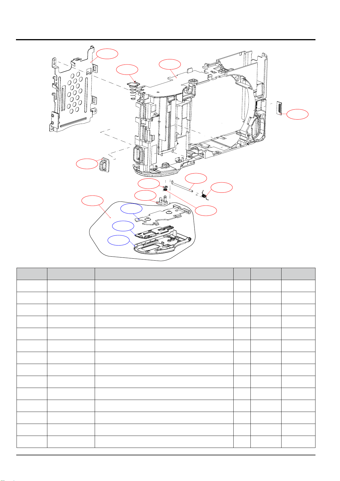
Exploded view and parts list
8-4 CHAMBER ASSEMBLY
4-2
4-4
4-14
4-3
4-6
4-5
4-10
4-8
4-1
4-13
4-11
4-12
4-9
4-7
Loc. No. Parts No. Description Qty Available Remark
4-1 AD64-03108A CHAMBER BODY 1 O
4-2 AD61-05669A PLATE CHAMBER 1 O
4-3 AD61-05213A SPRING-ETC BATTERY PUSH 1 O
4-4 AD61-05511A HOLDER-STRAP 1 O
4-5 AD61-05514A PLATE-BATTERY 1 X
4-6 AD63-06580A COVER-BATTERY-LOCK 1 X
4-7 AD63-06818A COVER-BATTERY 1 X
4-8 AD66-01012A LEVER-BATTERY LOCK 1 O
4-9 6107-001538 SPRING-TS(LOCK LEVER) 1 O
4-10 6044-001137 RING-E 1 O
4-11 AD61-05245A SPRING-ETC COVER BATTERY 1 O
4-12 AD61-05517A HINGE-COVER BATTERY 1 O
4-13 AD64-03681A GRILL SHEET SPEAKER 1 O
4-14 BATTERY COVER ASSY_BK 1 O
8-6
Copyrightⓒ 1995-2012 SAMSUNG. All rights reserved.
Page 71
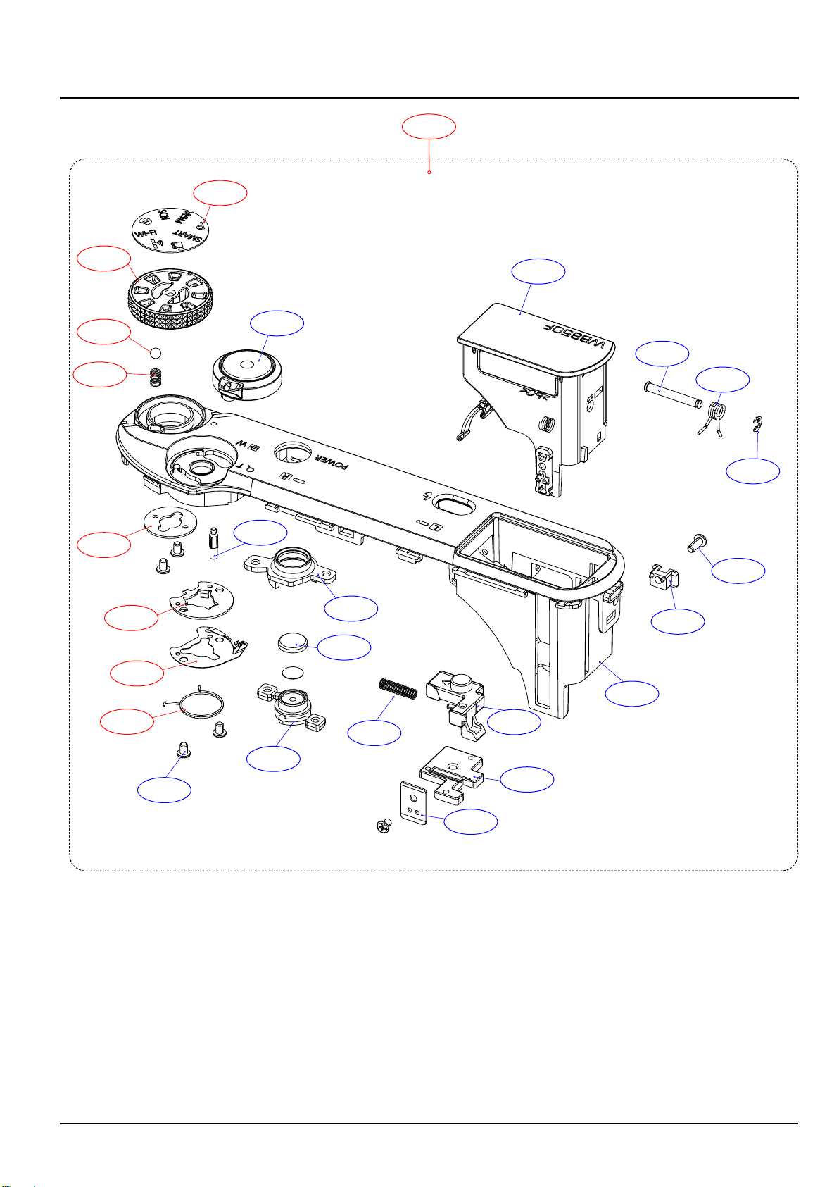
8-5 TOP COVER ASSSEMBLY
5-3
Exploded view and parts list
5-26
5-4
5-5
5-6
5-7
5-11
5-2
5-9
5-22
5-23
5-24
5-10
5-25
5-15
5-21
5-14
5-12
5-13
5-8
5-16
5-17
5-1
5-18
5-19
5-20
Copyrightⓒ 1995-2012 SAMSUNG. All rights reserved.
8-7
Page 72
Exploded view and parts list
Loc. No. Parts No. Description Qty Available Remark
5-1 AD63-06820A
5-2 AD97-22138A ASSY-POPUP FLASH 1 X
5-3 AD64-03703A DECO-COVER MODE_DIAL 1 O
5-4 AD64-03668A KNOB MODE DAIL 1 O
5-5 AD64-01738A CLICK BALL 1 O
5-6 AD61-05497A SPRING MODE DAIL 1 O
5-7 AD61-05383A PLATE MODE DAIL 1 O
5-8 6003-001661 SCREW 5 X
5-9 AD97-22139A ASSY-BUTTON ZOOM 1 X
5-10 AD64-03670A INDICATOR MODE 1 X
5-11 AD61-05673A PLATE ZOOM BUTTON 1 O
5-12 AD61-05674A PLATE ZOOM CONTACT 1 O
5-13 AD61-05707A SPRING-ETC ZOOM LEVER 1 O
5-14 AD67-02429A CAP BUTTON POWER 1 X
COVER-TOP
1 X
5-15 AD61-05667A HODER BUTTON POWER 1 X
5-16 AD64-03672A BUTTON POWER 1 X
5-17 6107-002668 SPRING FLASH (EX-1) 1 X
5-18 AD64-03673A BUTTON POP UP 1 X
5-19 AD64-03675A BUTTON POP UP INNER 1 X
5-20 AD61-05675A PLATE GUIDE POPUP 1 X
5-21 AD61-05668A GUIDE POPUP 1 X
5-22 AD61-05678A SHAFT HINGE_A 1 X
5-23 AD61-05681A SPRING-ETC_FLASH 1 X
5-24 6044-001137 RING-E 1 X
5-25 6003-001630 SCREW 1 X
5-26 AD97-22133A ASSY COVER-TOP_WB850F_RBK 1 O
8-8
Copyrightⓒ 1995-2012 SAMSUNG. All rights reserved.
Page 73
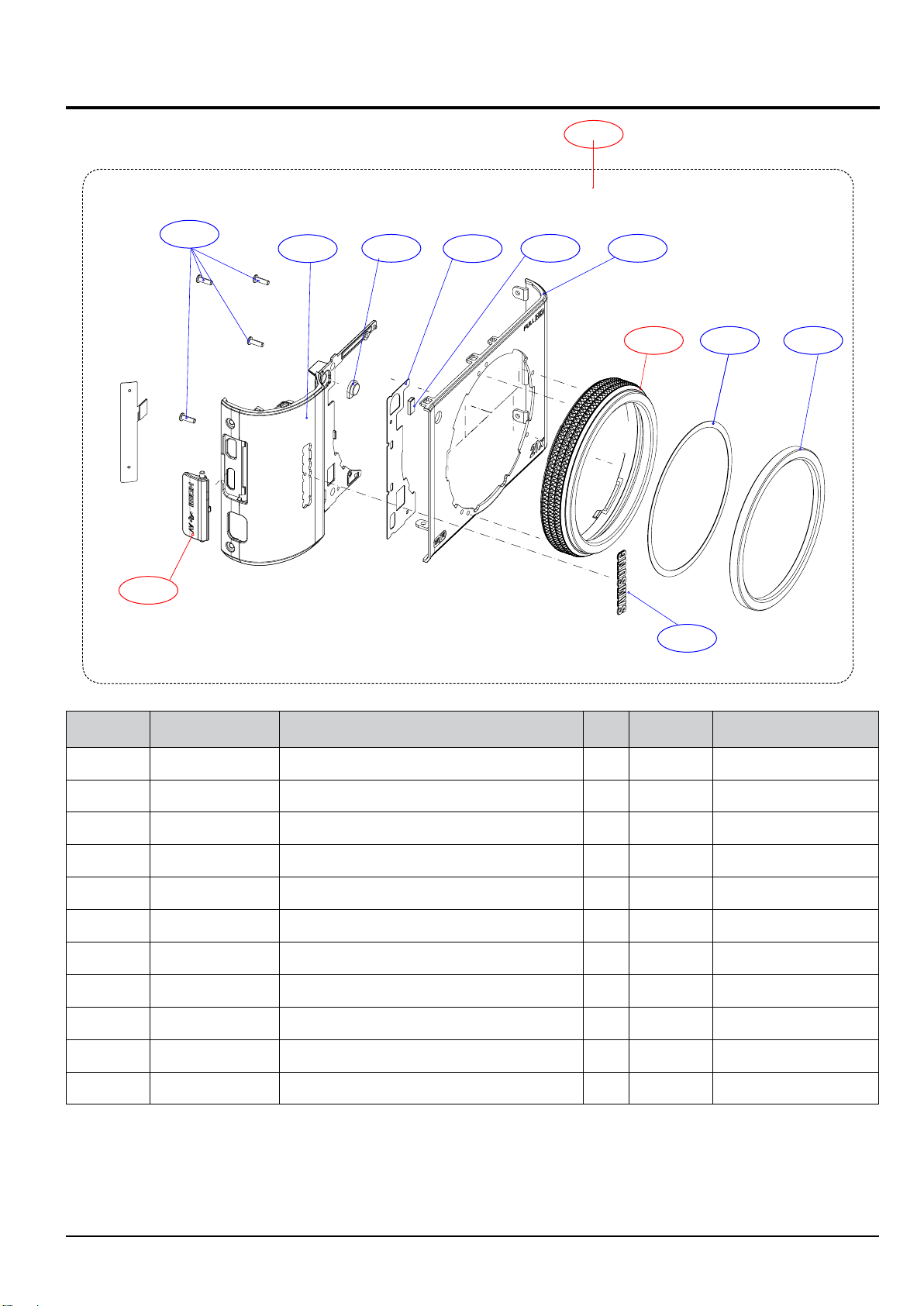
8-6 FRONT COVER ASSEMBLY
Exploded view and parts list
6-11
6-9
6-8
6-7
6-6
6-5
6-10
6-4
6-3
6-2 6-1
6-10
Loc. No. Parts No. Description Qty Available Remark
6-1 AD64-03677A DECORATION FRONT RING 1 X
6-2 AD63-06911A T-SHEET DECO RING 1 X
6-3 AD64-03698A DECORATION FRONT RING PC 1 O
6-4 AD63-06573A COVER FRONT 1 X
6-5 AD63-06837A T-SHEET FRONT 1 X
6-6 AD64-03095A WINDOW LED AF 1 X
6-7 AD63-06827A COVER FRONT GRIP 1 X
6-8 6003-001717 SCREW 4 X
6-9 AD63-06829A COVER SOCKET 1 O
6-10 AD64-03427A BADGE SAMSUNG LOGO 1 X
6-11 AD97-22135A FRONT COVER ASSY_BK 1 O
Copyrightⓒ 1995-2012 SAMSUNG. All rights reserved.
8-9
Page 74
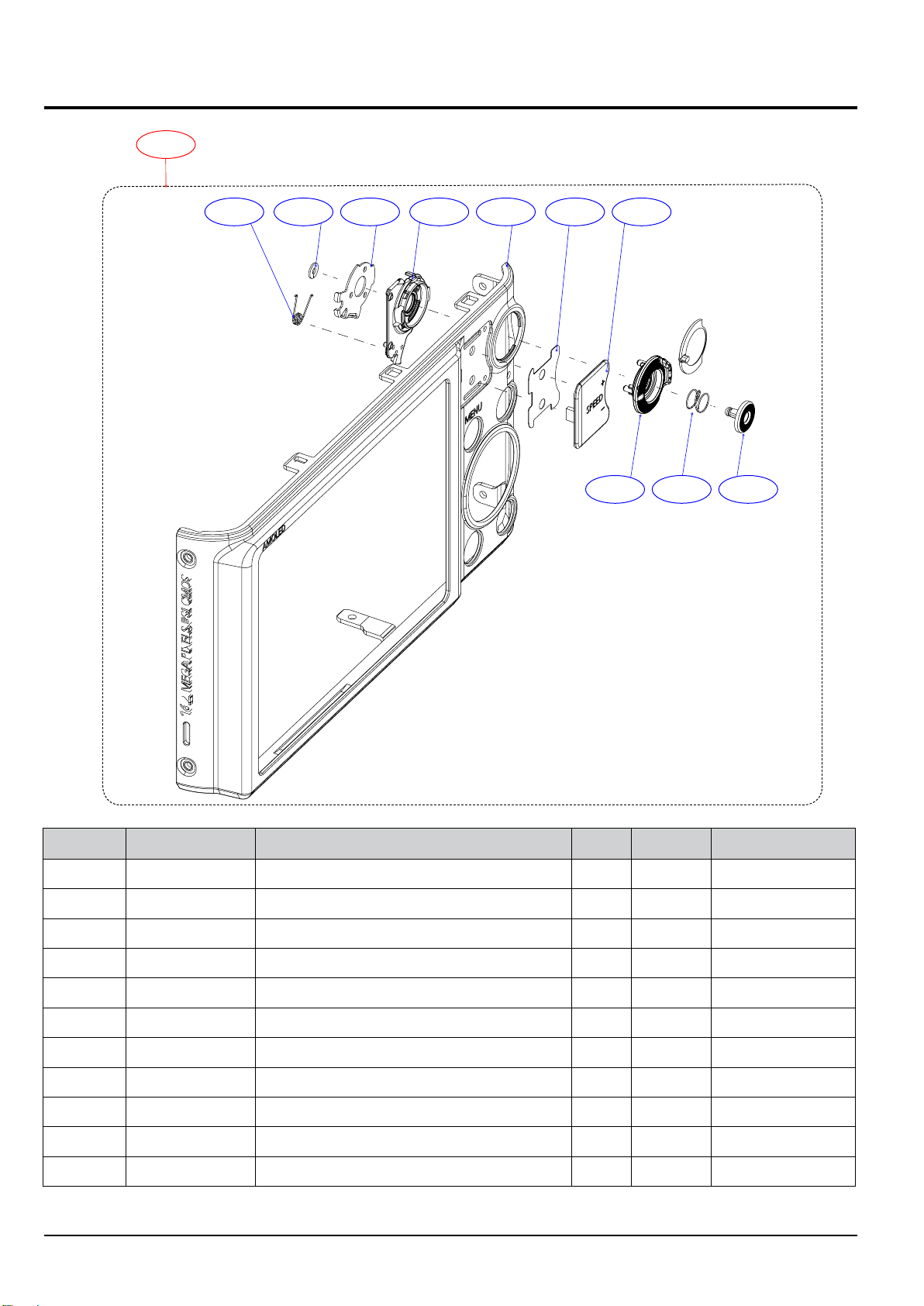
Exploded view and parts list
8-7 BACK COVER ASSEMBLY
7-11
7-10 7-9 7-8 7-7 7-6 7-5 7-4
7-3 7-2 7-1
Loc. No. Parts No. Description Qty Available Remark
7-1 AD64-03676A
7-2 AD61-05683A SPRING CS 1 X
7-3 AD66-01017A LEVER SPEED 1 X
7-4 AD63-06825A COVER BACK GRIP 1 X
7-5 AD63-06836A T/SHEET BACK GRIP 1 X
7-6 AD63-06825A COVER BACK 1 X
7-7 AD66-01018A LEVER SPEED INNER 1 X
7-8 AD61-05670A PLATE LEVER SPEED 1 X
7-9 6031-001628 WASHER PLAIN 1 X
7-10 AD61-05682A SPRING TS 1 X
7-11 AD97-22136A BACK COVER ASSY_BK 1 O
8-10
BUTTON REC
1 X
Copyrightⓒ 1995-2012 SAMSUNG. All rights reserved.
Page 75
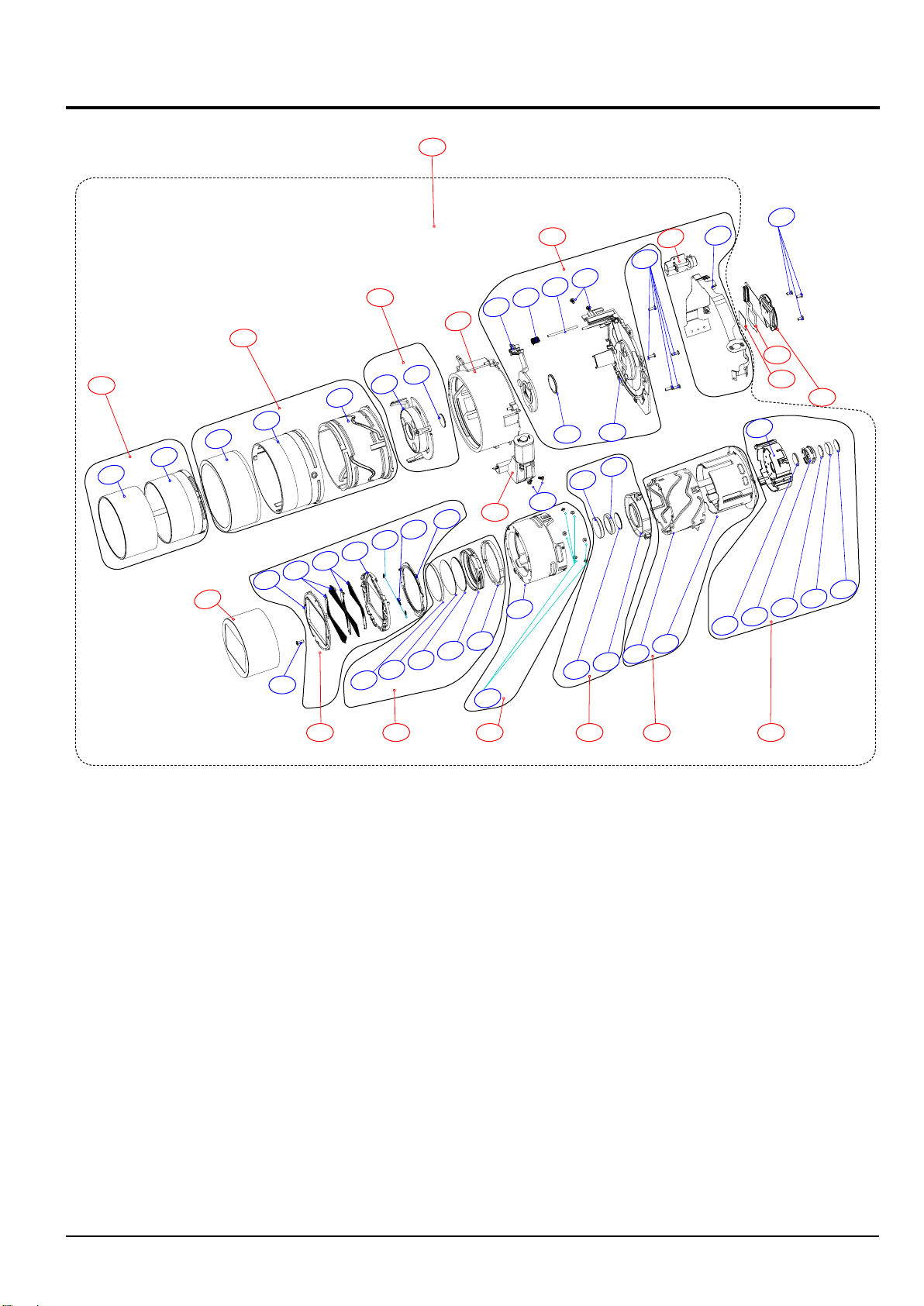
8-8 BARREL ASSEMBLY
8-59
8-57
8-32
8-31
8-30
8-29
8-3
8-1
8-2
8-4
8-5
8-33
8-6
8-10
8-54
8-34
8-7
8-11
8-62
8-35
8-8
8-12
8-36
8-9
8-13
8-37
8-14
8-16
8-39
8-41
8-15
8-60
8-42
8-38
8-40
8-19
8-43
8-17
8-44
8-18
8-20
8-45
8-21
Exploded view and parts list
8-51
8-46
8-22
8-47
8-24
8-23
8-25
8-49
8-48
8-26
8-27
8-50
8-28
8-61
8-53
8-56
8-52
8-58
8-55
Copyrightⓒ 1995-2012 SAMSUNG. All rights reserved.
8-11
Page 76
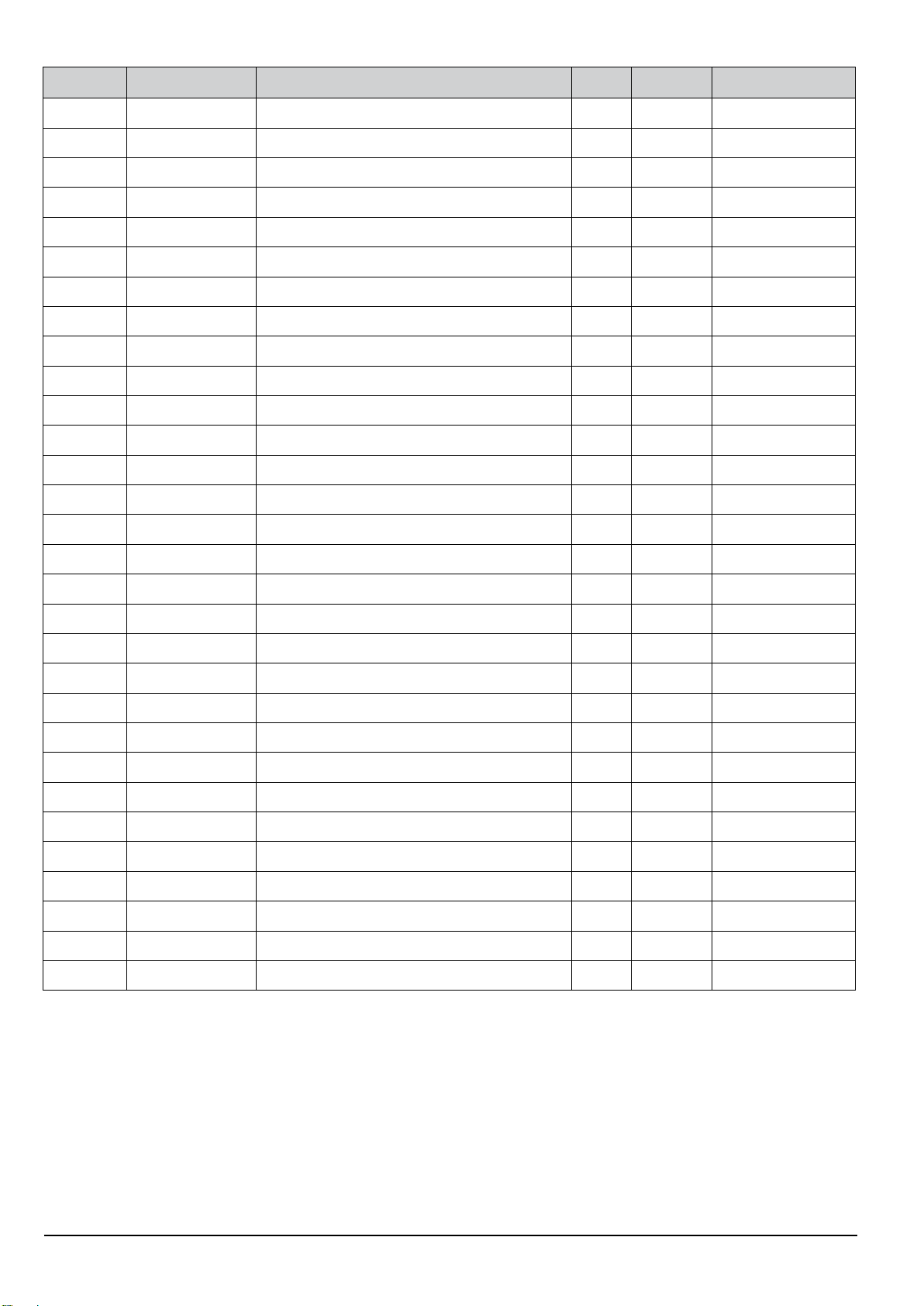
Exploded view and parts list
Loc. No. Parts No. Description Qty Available Remark
8-1 AD64-03548A
8-2 6003-001659 SCREW TAPTYPE 1 X
8-3 AD63-06546A BARRIER PANEL 1 X Royal Black
8-4 AD63-06547A BARRIER BLADE A 2 X Royal Black
8-5 AD63-06548A BARRIER BLADE B 2 X Royal Black
8-6 AD63-06544A BARRIER BASE 1 X
8-7 6107-003266 SPRING ES (CLOSE) 2 X
8-8 6107-003265 SPIRNG EX (OPEN) 1 X
8-9 AD63-06545A BARRIER LEVER 1 X
8-10 AD67-02346A LENS G1 1 X
8-11 AD67-02347A LENS G2 1 X
8-12 AD67-02348A LENS G3 1 X
8-13 AD67-02394A BARREL 1ST 1 X
8-14 AD67-02395A BARREL SLIPRING 1 X
8-15 AD67-02393A BARREL ZOOMRING 1 X
8-16 AD66-00990A SHAFT ZOOMRING PIN 6 X
DECORING ZOOMRING
1 O Royal Black
8-17 AD67-02349A LENS G4 1 X
8-18 AD67-02350A LENS G5 1 X
8-19 AD67-02351A LENS G6 1 X
8-20 AD67-02396A BARREL 2ND 1 X
8-21 AD67-02390A BARREL INNER CAM 1 X
8-22 AD67-02392A BARREL GUIDE 1 X
8-23 AD97-21686A ASSY SHUTTER OIS 1 X
8-24 AD67-02352A LENS G7 1 X
8-25 AD67-02397A BARREL 3RD 1 X
8-26 AD67-02353A LENS G8 1 X
8-27 AD67-02354A LENS G9 1 X
8-28 AD67-02355A LENS G10 1 X
8-29 AD64-03549A DECORING CAM 1 X Royal Black
8-30 AD67-02391A BARREL CAM 1 X
8-12
Copyrightⓒ 1995-2012 SAMSUNG. All rights reserved.
Page 77
Exploded view and parts list
Loc. No. Parts No. Description Qty Available Remark
8-31 AD64-03550A
8-32 AD67-02388A BARREL OUTER CAM 1 X
8-33 AD67-02389A BARREL OUTER GUIDE 1 X
8-34 AD67-02398A BARREL 4TH 1 X
8-35 AD67-02356A LENS G11 1 X
8-36 AD97-21783A BARREL BASE 1 O
8-37 AD97-21685A ASSY MOTOR ZOOM 1 O
8-38 6003-001629 SCREW TAPTYPE 2 X
8-39 AD67-02399A BARREL 5TH 1 X
8-40 AD67-02357A LENS G12 1 X
8-41 6107-003264 SPRING CS (AF) 1 X
8-42 AD66-00991A SHAFT AF GUIDE 1 X
8-43 6003-001629 SCREW TAPTYPE 2 X
8-44 AD61-05502A BASE LENS 1 X
8-45 6003-001659 SCREW TAPTYPE 5 X
8-46 AD97-21684A ASSY MOTOR AF 1 O
DECORING OUTER CAM
1 X Royal Black
8-47 AD92-01774A FPC BARREL MAIN 1 X
8-48 AD63-03625A IR CUT FILTER 1 O
8-49 AD63-06759A SHEET FILTER 1 O
8-50 AD92-01802A ASSY PCB FPC-CIS 1 O
8-51 6003-001633 SCREW TAPTYPE 3 X
8-52 AD97-21760A ASSY SUB BARREL-2ND LENS O
8-53 AD97-21764A ASSY SUB BARREL-SLIPRING O
8-54 AD97-21762A ASSY SUB BARREL-4TH LENS O
8-55 AD97-21765A ASSY SUB BARREL-OIS O
8-56 AD97-21766A ASSY SUB BARREL-ZOOMRING O
8-57 AD97-21767A ASSY SUB BARREL-CAM_BK O Royal Black
8-58 AD97-21768A ASSY SUB BARREL-INNER CAM O
8-59 AD97-21769A ASSY SUB BARREL-OUTER CAM_BK O Royal Black
8-60 AD97-21770A ASSY LENS BASE O
8-61 AD97-21771A ASSY BARRIER_BK O Royal Black
8-62 AD97-21773A ASSY BARREL_BK O Royal Black
Copyrightⓒ 1995-2012 SAMSUNG. All rights reserved.
8-13
Page 78
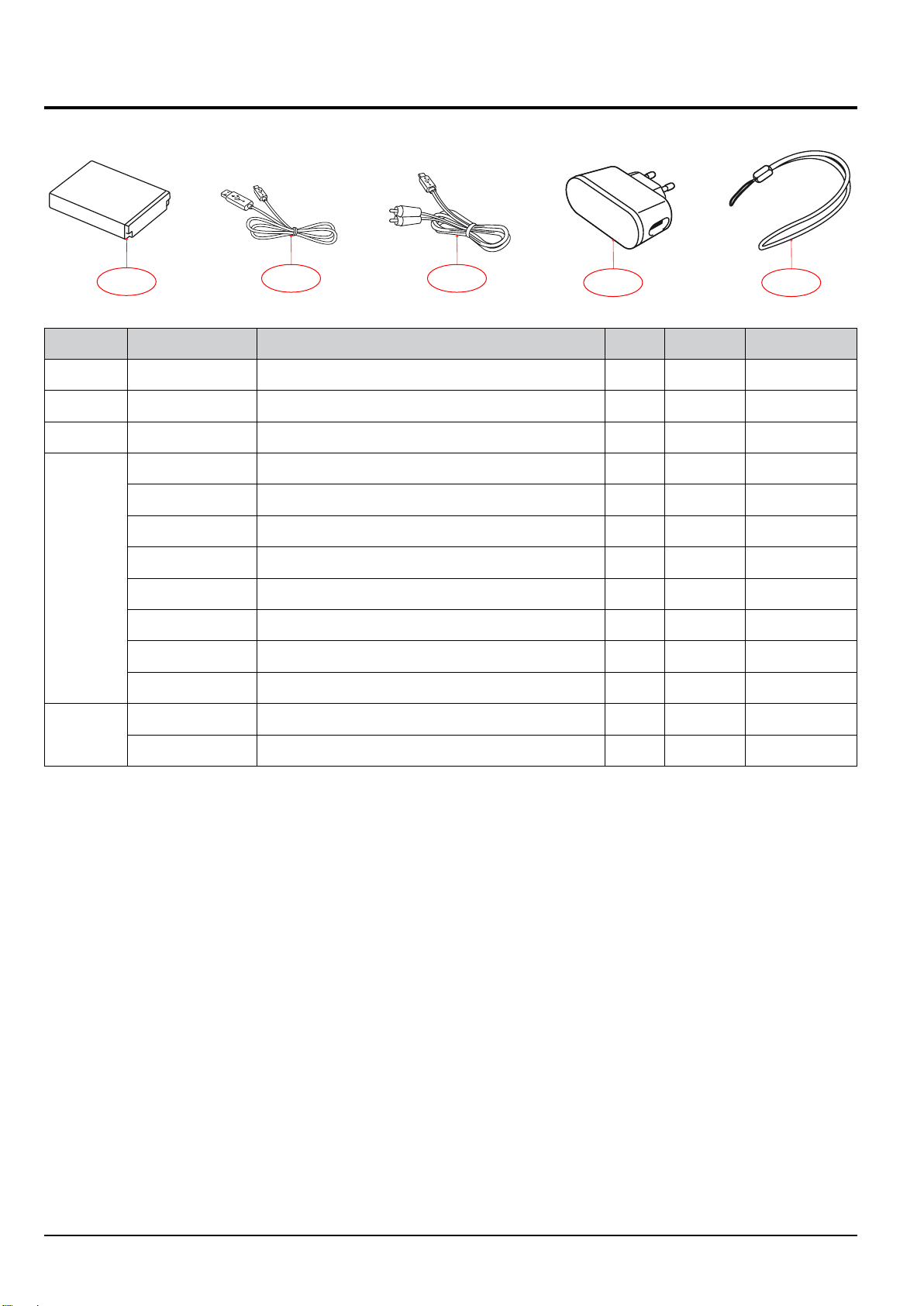
Exploded view and parts list
8-9 PACKING ITEMS
9-1
Loc. No. Parts No. Description Qty Available Remark
9-1 4302-001221 LITHIUM-ION_SLB-10A 1 O
9-2 AD39-00190A CB5MU05E_USB CABLE 1 O
9-3 AD39-00146A CBF IF(20PIN_AV_CABLE_SCC-AV20) 1 O
AD44-00178A AC ADAPTOR_AD5055_KOR 1 O
AD44-00184A AD5055_CHI 1 O
AD44-00183A AD5055_EXP 1 O
AD44-00179A AD5055_USA 1 O
9-4
AD44-00182A AD5055_UK 1 O
AD44-00185A AD5055_AUS 1 O
AD44-00181A AD5055_ARG 1 O
AD44-00180A AD5055_BRA 1 O
AD63-02604A STRAP_KENOX_S860_BLACK 1 O
9-5
AD63-02596A STRAP_KENOX_S730_SILVER 1 O
9-2 9-3
9-4 9-5
8-14
Copyrightⓒ 1995-2012 SAMSUNG. All rights reserved.
Page 79
Area Web Site
Europe, MENA, CIS, Africa https://gspn1.samsungcsportal.com
E.Asia, W.Asia, China, Japan https://gspn2.samsungcsportal.com
N.America, S.America https://gspn3.samsungcsportal.com
This service manual is a property of Samsung Electronics Co.,Ltd.
Any unauthorized or attempted unauthorized use of this service
manuel is strictly prohibited and may be punishable under applicable
international and/or domestic law.
© 2012 SAMSUNG Electronics Co.,Ltd
All rights reserved.
Printed in Korea March, 2012
Code No: EC-WB850F/WB855F
 Loading...