

Samsung WA31273A, WA32543A, WA33203A, WA32163A, WA31083A Technical Manual
...
Technical Manual
3.5” Hard Disk Drives
Winner 3A / 2A
WA31273A / WA32543A
WA33203A / WA31083A
WA32163A / WA32162A
FEBRUARY,1998(REV.D)

Winner 3A
WA31273A / WA32543A / WA33203A
WA31083A / WA32163A
Winner 2A WA32162A
OEM Technical Manual
This TECHNICAL MANUAL may contain some technical inaccuracies or
typographical errors. Changes are periodically made to the information herein,
these changes will be incorporated in new editions of this publication. SAMSUNG
may make improvements and/or changes in the product(s) described in this
publication at any time.
(c) Copyright SAMSUNG ELECTRONICS CO., LTD. 1997. All rights reserved.
Requests for technical information about this product to SAMSUNG Electronics,
Storage System Division, 94-1 IM SOO-DONG, KUMI CITY, KYUNG BUK,
KOREA.
Trademark Acknowledgments
PC-AT and PC-XT are registered trademarks of International Business Machines
Corporation, Microsoft is a U.S. registered trademark and MS-DOS (DOS) and
Windows are registered trademarks of Microsoft Corporation. UNIX is a
registered trademark of AT&T, Bell Laboratories. All other product names used
in this publication are for identification purposes only and may be trademarks of
their respective companies.

WA31273A / WA32543A / WA33203A / WA32163A / WA31083A / WA32162A 1-1
Chapter 1
SCOPE
This chapter gives an overview of the contents of this manual, including the intended user,
manual organization, terminology and conventions. In addition, it provides a list of other
references that might be helpful to the reader.
1-1 User Definition
The Winner 3A WA31273A / WA32543A / WA33203A / WA32163A / WA31083A, Winner 2A
WA32162A technical manual is intended for the following readers:
• Original Equipment Manufacturers (OEMs)
• Distributors
1-2 Manual Organization
This manual provides information about installation, principles of operation, and interface
command implementation. It is organized into the following chapters:
• Chapter 1 - Scope
• Chapter 2 - Overall Description
• Chapter 3 - Specifications
• Chapter 4 - Installation and Operation
• Chapter 5 - Disk Drive Operation
• Chapter 6 - AT Interface and ATA Commands
• Chapter 7 - Maintenance
In addition, this manual contains a glossary of terms to help you understand important
information.

Scope
1-2 WA31273A / WA32543A / WA33203A / WA32163A / WA31083A / WA32162A
1-3 Terminology and Conventions
The abbreviations listed below are used in this manual
µinches
Microinches(10
-6
inches)
µs
Microseconds
BPI Bits per inch
dB Decibels
FCI Flux changes per inch
GB Gigabytes
Hz Hertz
Kbytes Kilobytes
lbs Pounds
M Meter
mA Milliampere
MB Megabytes
Mbit/s Megabits per second
Mbytes/s Megabytes per second
MHz Megahertz
mil Millinches
ms Milliseconds
mV Millivolts
ns Nanoseconds
RPM Rotations per minute
TPI Tracks per inch
V Volts
W Watts
This manual uses the following convention:
•
Computer Message
Computer message refers to items you type at the computer keyboard. These items are listed
in all capitals in Courier New font. For example:
FORMAT C:/S
• Commands and Messages
Interface commands and messages sent from the drive to the host are listed in all capitals. For
example:
READ CONFIGURATION
WRITE LONG

Scope
WA31273A / WA32543A / WA33203A / WA32163A / WA31083A / WA32162A 1-3
• Parameters
Parameters are given as initial capitals when spelled out and as all capitals when abbreviated.
For example:
Prefetch Enable : PE
Cache Enable : CE
• Names of Bits and Registers
Bit names and register names are presented in initial capitals. For example:
Host Software Reset
Sector Count Register
• Hexadecimal Notation
Hexadecimal notation is identified using the small letter form. For example:
30h
• Signal Negation
A signal name is defined as active low is listed with a dash character following the signal. For
example:
RD-
• Notes
Notes are used after tables to provide you with supplementary information.
• Host
In general, the system in which the drive resides is referred to as the host.
1-4 Reference
For additional information about the AT interface, refer to:
• ATA-3 (AT Attachment 3), Revision 7B, 27 January, 1997

WA31273A / WA32543A / WA33203A / WA32163A / WA31083A / WA32162A 2-1
Chapter 2
OVERALL DESCRIPTION
This chapter summarizes general functions and key features of Winner 3A WA31273A /
WA32543A / WA33203A / WA32163A / WA31083A, Winner 2A WA32162A drives, as well as
the standards and regulations they meet.
2-1 Introduction
The Samsung Winner 3A WA31273A / WA32543A / WA33203A / WA32163A /
WA31083A, Winner 2A WA32162A 3.5 inch disk drives are low cost, high capacity, high
performance random access devices which use non removable 3.5 inch disk(s) as storage
media. The disk is used of thin film metallic media technology for enhanced
performance. Each disk surface employs one movable head to access the data tracks. The
formatted capacity is 1.27, 2.54, 3.2, 2.16, 1.08, and 2.16 gigabytes of storage, respectively.
The Winner 3A WA31273A / WA32543A / WA33203A / WA32163A / WA31083A,
Winner 2A WA32162A drives include the AT controller embedded in the disk drive PCB
electronics. The drive's electrical interface is compatible with the mandatory, optional
and vendor specific commands.
Drive size conforms to the industry standard 3.5 inch form factor. The interface
connectors are the standard 40 pin for AT Interface and 4 pin for DC power supplies.
High capacity is achieved by using Advanced Thin Film Inductive head and PRML
(Partial Response Maximum Likelihood) recording method. This method can increase
capacity by increasing the areal density of the drive..
High performance and low cost are achieved through the use of a rotary voice coil
actuator and an embedded servo system. Embedded servo technology uses special
information recorded on each data cylinder to maintain position accuracy. This
technique assures recording head position accuracy in read or write operations at all
temperatures.
The heads, disk and actuator housing is environmentally sealed. Air circulates within
the HDA through a non-replaceable recirculating filter to ensure the maintenance of a
contamination free disk and actuator environment.

Overall Description
WA31273A / WA32543A / WA33203A / WA32163A / WA31083A / WA32162A 2-2
2-2 Key features
Key features of the Winner 3A WA31273A / WA32543A / WA33203A / WA32163A /
WA31083A, Winner 2A WA32162A hard disk drives include:
• Formatted capacity of 1.27, 2.54, 3.2, 2.16, 1.08, 2.16 Gbytes respectively.
• Low-profile, 1-inch height form factor
• 11 msec average seek time
• High accuracy rotary voice coil actuator with embedded sector servo
• Fast ATA-3/E-IDE interface
• Power management for "Green PC"
• ATA standard PIO Mode 0-4/DMA Mode 0-2
• Supports for both CHS and LBA Addressing mode
• Supports for all logical geometries as programmed by the host
• Proprietary 128K read look-ahead cache with a segmented buffer and write stacking
capability
• 1:1 interleave on read/write operation
• Transparent media defect mapping
• High performance in-line defective sector skipping
• Automatic error correction and retries
• Optimized 144-bit ECC with triple burst on-the-fly(OTF) correction
• Ability to daisy-chain two drives on the interface
• Automatic magnet latch achieving zero power consumption
• PRML Read channel
• Pseudo Contact Recording, Thin Film Inductive heads

Overall Description
WA31273A / WA32543A / WA33203A / WA32163A / WA31083A / WA32162A 2-3
2-3 Standards and regulations
The Winner 3A WA31273A / WA32543A / WA33203A / WA32163A / WA31083A,
Winner 2A WA32162A depends upon its host equipment to provide proper power and
environment to achieve optimum performance and compliance with applicable industry
and governmental regulations. Special attention has been given in the areas of safety,
power distribution, shielding, audible noise control, and temperature regulation.
The Winner 3A WA31273A / WA32543A / WA33203A / WA32163A / WA31083A,
Winner 2A WA32162A hard disk drives satisfy the following standards and
regulations :
• Underwriters Laboratory (UL) : Standard 1950. Information technology equipment
including business equipment.
• Canadian Standards Association (CSA) : Standard C22.2 No.3000-201 Information
technology equipment including business equipment.
• Technisher Überwachungs Verein (TÜV) : Standard EN 60 950. Information
technology equipment including business equipment.
• CE
2-4 Hardware requirements
Winner 3A WA31273A / WA32543A / WA33203A / WA32163A / WA31083A, Winner
2A WA32162A hard disk drives are compatible with host computers and controllers that
are PC/AT compatible. They are connected to a PC either by:
• Using an adapter board
• Plugging a cable from the drive directly into a PC motherboard with an IDE
(Integrated Drive Electronics) interface.
WA31273A / WA32543A / WA33203A / WA32163A / WA31083A / WA32162A 3-1
Chapter 3
SPECIFICATIONS
This chapter gives a detailed description of the physical, electrical, and environmental
characteristics of the Winner 3A WA31273A / WA32543A / WA33203A / WA32163A /
WA31083A, Winner 2A WA32162A hard disk drives.
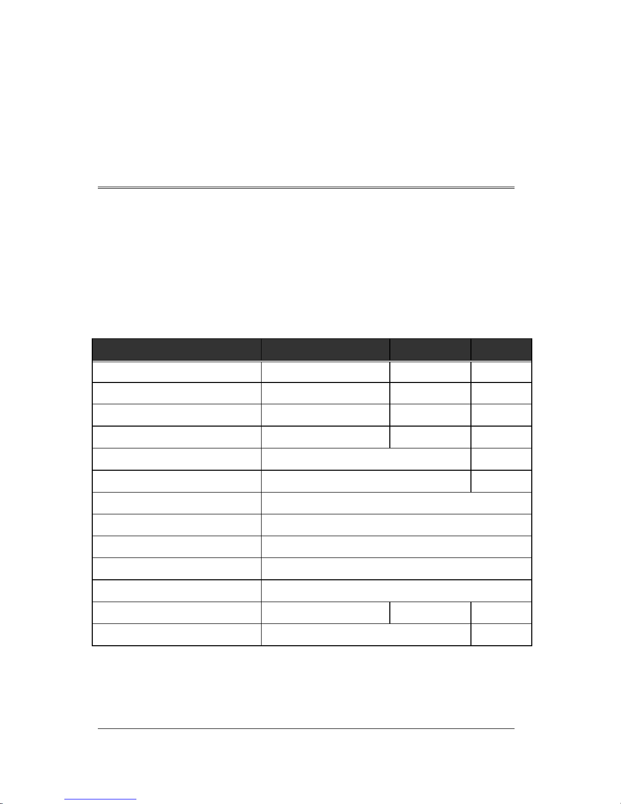
3-1 Specification Summary
TABLE 3-1. Specifications
DESCRIPTION
WA31273A / WA32543A /
WA33203A
WA31083A /
WA32163A
WA32162A
Number of disks 1 / 2 / 3 1 / 2 2
Number of R/W heads 2 / 4 / 5 2 / 4 4
Maximum recording density (BPI) 124,925 107,829 117,598
Maximum flux density (FCI) 140,541 121,308 132,298
Track density (TPI) 6,900 6,000
Data tracks per surface 6,740 5,963
Encoding method 8,9 GCR
Interface method Fast ATA-3/E-IDE
Acturator type Rotary Voice Coil
Servo type Embedded Sector Servo
Number of Cylinder Reserved 4
Maximum Data Transfer Rate(Mb/s)
107.9 92.86 86.67
Spindle speed (rpm)
5,400 ± 0.1% 4,500±0.1%
Specifications
3-2 WA31273A / WA32543A / WA33203A / WA32163A / WA31083A / WA32162A
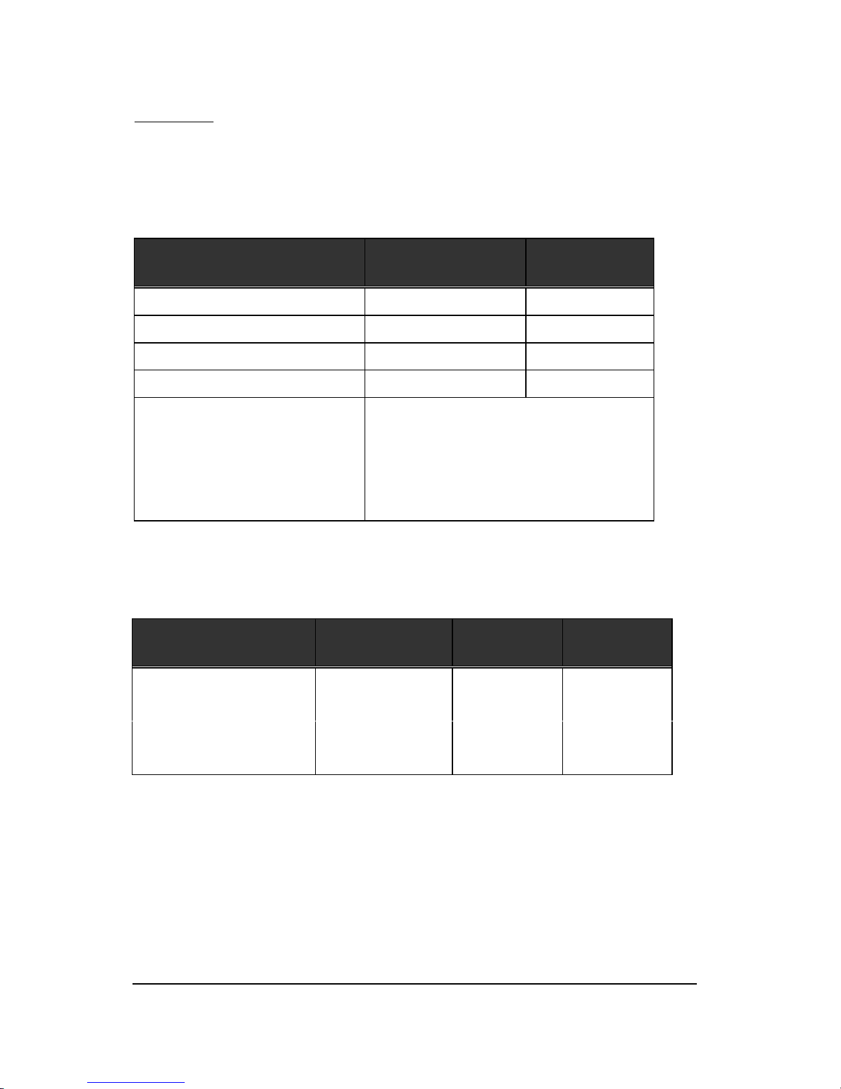
3-2 Physical Specifications
TABLE 3-2. Physical specifications
DESCRIPTION
WA31273A / WA32543A /
WA33203A / WA32163A /
WA31083A
WA32162A
Track pitch (µinches) 154 167
Data head flying height (µinches) 0.8 1.01
Inner most data track radius (inches) 0.8413 0.8291
Outer most data track radius (inches) 1.7841 1.8090
Physical dimensions :
Length (inches)
Width (inches)
Height (inches)
Weight (lbs)
5.75
4.00
1.00
1.2
3-3 Logical Configurations
TABLE 3-3. Logical configurations
DESCRIPTION
WA31273A
WA32543A
WA33203A
WA31083A
WA32163A
WA32162A
Default logical mode :
Number of cylinders
2,481
4,962
6,203
2,094
4,190
4,186
Number of heads 16 16 16
Number of sectors 63 63 63
Specifications
WA31273A / WA32543A / WA33203A / WA32163A / WA31083A / WA32162A 3-3
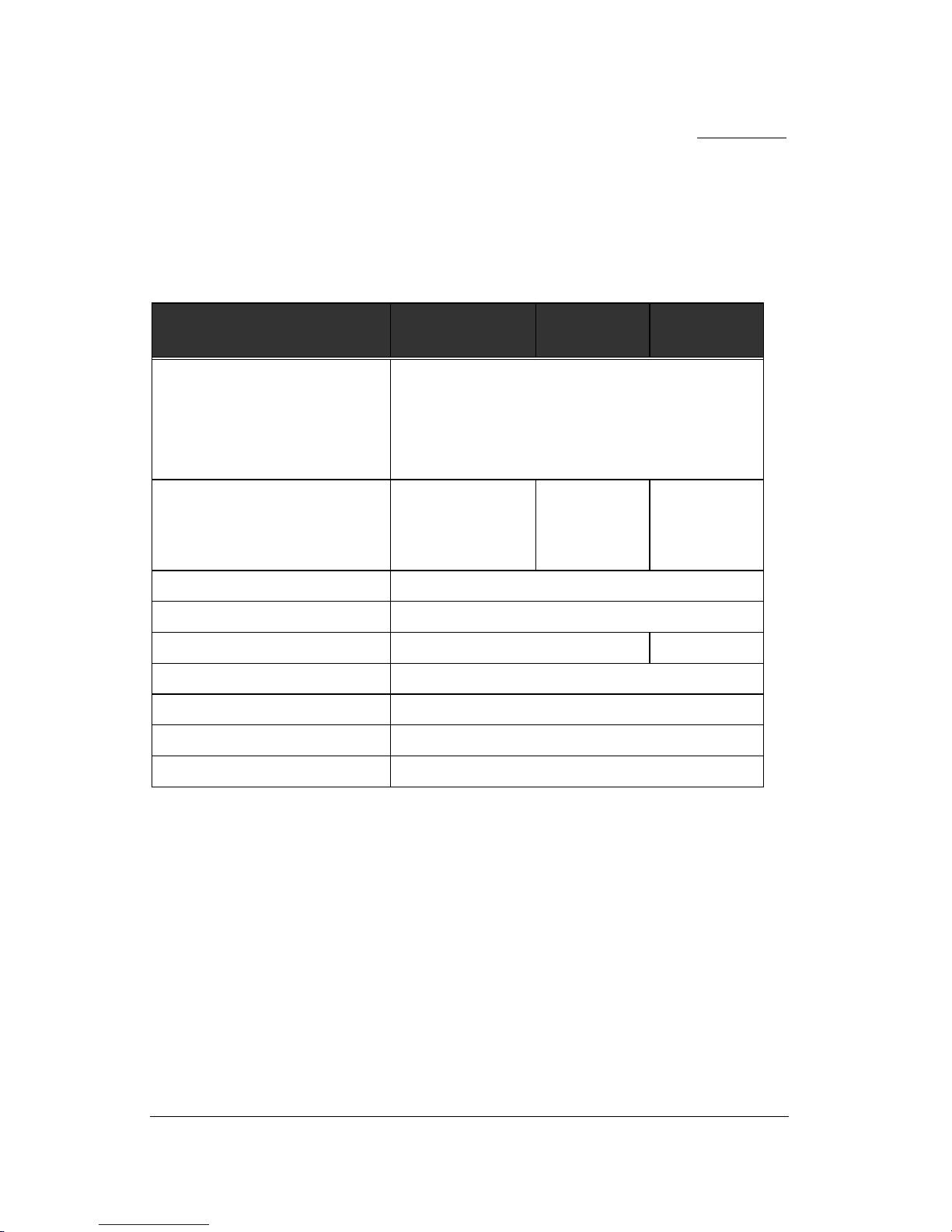
3-4 Performance Specifications
TABLE 3-4. Performance specifications
DESCRIPTION
WA31273A
WA32543A
WA33203A
WA31083A
WA32163A
WA32162A
Seek Time (typical) :
Average seek time
Track to track seek time
Full stroke seek time
<11 msec
2 msec
<20 msec
Data Transfer Rate :
Maximum to/from media
Maximum to/from buffer
107.9 Mbits/s
16.6 Mbytes/s
92.86 Mbits/s
16.6Mbytes/s
86.67 Mbits/s
16.6Mbytes/s
Average latency 5.6 msec
Controller overhead < 0.5 msec
Rotational Speed 5,400± 0.1% rpm 4500±0.1% rpm
Motor spin up time (Typical) 15 sec
Motor spin down time (Typical) 7 sec
Interleave 1 : 1
Buffer size 128 KBytes
NOTES : ∗ The seek time is defined as the time for the actuator to seek and settle on the
desired track with the drive operating at nominal DC input voltages and
nominal operating temperature.
∗ The average seek time is determined by averaging the seek time for 1,000 seeks
of random length.
∗ The spin up time is the time elapsed between the supply voltages reaching
operating range and the drive being ready to accept all commands.
∗ The controller overhead is the time it takes to start a seek after the drive has been
selected.
∗ The average latency time is the time needed for another 1/2 revolution after seek
completion.

Specifications
3-4 WA31273A / WA32543A / WA33203A / WA32163A / WA31083A / WA32162A
3-5 Power Reguirements
TABLE 3-5. Power requirements (EX : WA32543A)
Mode
Typical Current
(mA rms)
Typical Power
(Watts)
Maximum
Power (Watts)
+5 Volts
+12 Volts
Spin-up 564 1195 14.4 17.06
Normal Read/Write 477 249 4.92 5.27
Idle 216 225 3.38 3.70
Random Seek 481 521 8.31 8.59
Standby 198 78 1.68 1.91
Sleep 120 78 1.34 1.52
NOTES * Random seek means seek commands with logical random location and 30%
duty cycle.
* Random read/write means a combination of random write 256 sectors
commands and random read 256 sectors command
Specifications
WA31273A / WA32543A / WA33203A / WA32163A / WA31083A / WA32162A 3-5
3-6 Environmental Specifications
TABLE 3-6. Environmental specifications
DESCRIPTION
WA31273A / WA32543A / WA33203A /
WA32163A / WA31083A / WA32162A
Ambient Temperature :
Operating
Non-operating
Maximum gradient without
Condensation
5∼55°C
-40∼65°C
20°C/hr
Relative Humidity : (non-condensing)
Operation
Non-operation
Maximum wet bulb temperature :
operating
non-operating
8∼80 %
8∼95 %
29 °C
40 °C
Altitude (relative to sea level) :
Operating
Non-operating
-200 to 10,000 ft.
-1,000 to 40,000 ft.
Vibration (1 oct/min sweep sine) :
Operating
5-21Hz
22-400Hz
Non-operating
5-21Hz
22-500Hz
0.034"(double amplitude)
1.5 G (p-p)
0.195"(double amplitude)
8.0 G (p-p)
Shock : (1/2 sine pulse, 11ms duration)
Operation
Non-operating
10 G's
75 G's
Specifications
3-6 WA31273A / WA32543A / WA33203A / WA32163A / WA31083A / WA32162A
TABLE 3-6. Environmental specifications (continued)
DESCRIPTION
WA31273A / WA32543A / WA33203A /
WA32163A / WA31083A / WA32162A
Acoustic Noise (Max.Sound Pressure):
Idle
Random Read/Write
< 35 dBA
< 40 dBA
NOTE : The Winner 3A WA31273A / WA32543A / WA33203A / WA32163A / WA31083A, Winner
2A WA32162A hard disk drives can withstand levels of shock and vibration applied
to any of its three mutually perpendicular axes, as in the specifications for shock
and vibration. When packed in its shipping container, the Winner 3A WA31273A /
WA32543A / WA33203A / WA32163A / WA31083A, Winner 2A WA32162A can
withstand a drop from 90cm (5Kg/Box), onto a concrete surface - on any of its six
surfaces, three edges, and one corner. The drive can withstand vibration applied to
the container of 5-500Hz (p-p), 1.5G.
WA31273A / WA32543A / WA33203A / WA32163A / WA31083A / WA32162A 4-1
Chapter 4
INSTALLATION AND OPERATION
This chapter describes how to unpack, mount, configure, and connect the Winner 3A
WA31273A / WA32543A / WA33203A / WA32163A / WA31083A, Winner 2A
WA32162A hard disk drive. It also describes how to start and operate the drive.
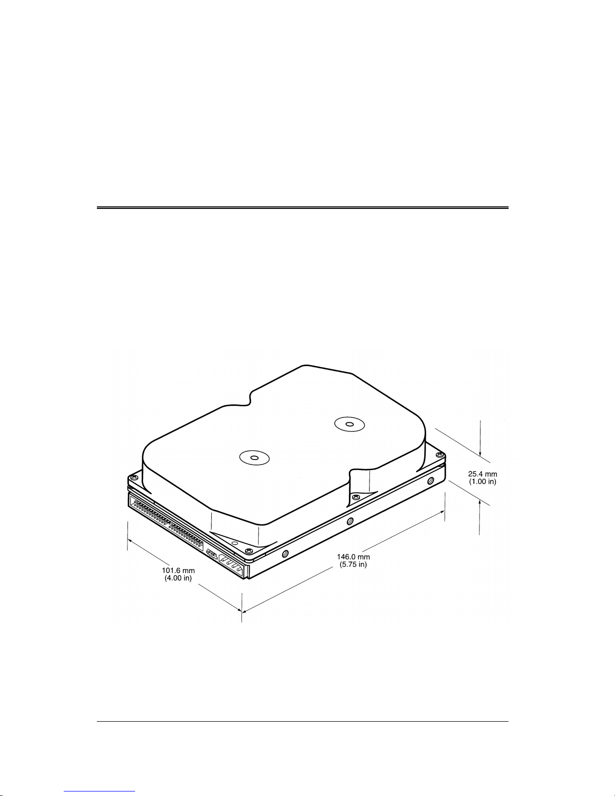
4-1 Space Requirements
SAMSUNG ships the Winner 3A WA31273A / WA32543A / WA33203A / WA32163A /
WA31083A, Winner 2A WA32162A hard disk drives without a bezel. Figure 4-1 shows
the external dimensions of the drive.
Figure 4-1. Mechanical Dimensions

Installation and Operation
4-2 WA31273A / WA32543A / WA33203A / WA32163A / WA31083A / WA32162A
4-2 Unpacking Instructions
(1) Open the shipping container of the Winner 3A WA31273A / WA32543A /
WA33203A / WA32163A / WA31083A, Winner 2A WA32162A
(2) Lift the packing assembly that contains the drive out of the shipping container.
(3) Remove the drive from the packing assembly. When you are ready to install the
drive, remove it from the ESD (Electro Static Discharge) bag.
CAUTION : During shipment and handling the anti static ESD bag prevents
electronic component damage due to electrostatic discharge. To avoid accidental
damage to the drive, do not use a sharp instrument to open the ESD bag.
(4) Save the packing material for possible future use.
4-3 Mounting
(1) Be sure that the system power is off.
(2) Mount the drive in a mounting slot of your system. For mounting, use six #32 UNC
screws.
CAUTION : To avoid stripping the mounting-hole threads, the maximum torque
applied to the screws must not exceed 8.0 Kg-cm (6.95 inch-pounds).
Installation and Operation
WA31273A / WA32543A / WA33203A / WA32163A / WA31083A / WA32162A 4-3
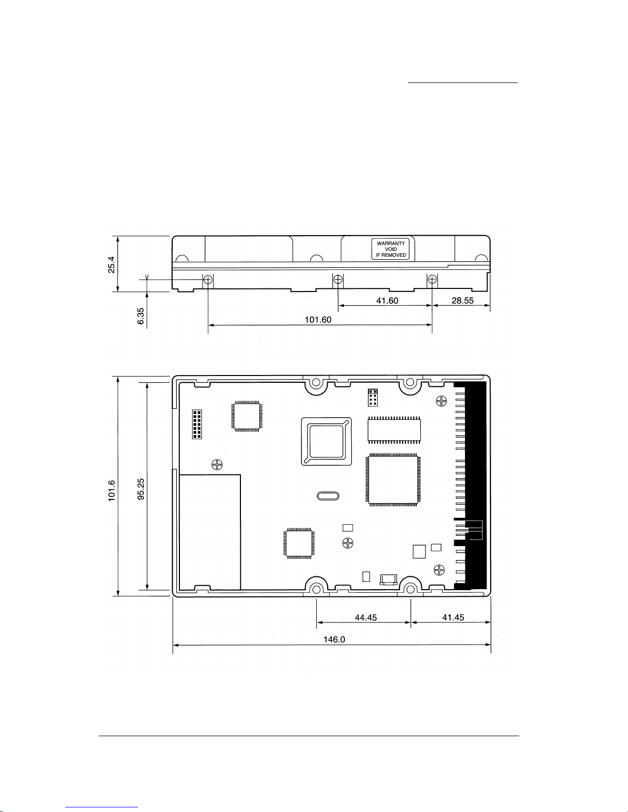
4-3-1 Orientation
Figure 4-2 shows the physical dimensions and mounting holes located on each side of
the drive. The mounting holes on the Winner 3A WA31273A / WA32543A / WA33203A
/ WA32163A / WA31083A, Winner 2A WA32162A hard disk drive allow the drive to be
mounted in any orientation.
Figure 4-2. Mounting Dimensions (in Millimeters)
Installation and Operation
4-4 WA31273A / WA32543A / WA33203A / WA32163A / WA31083A / WA32162A
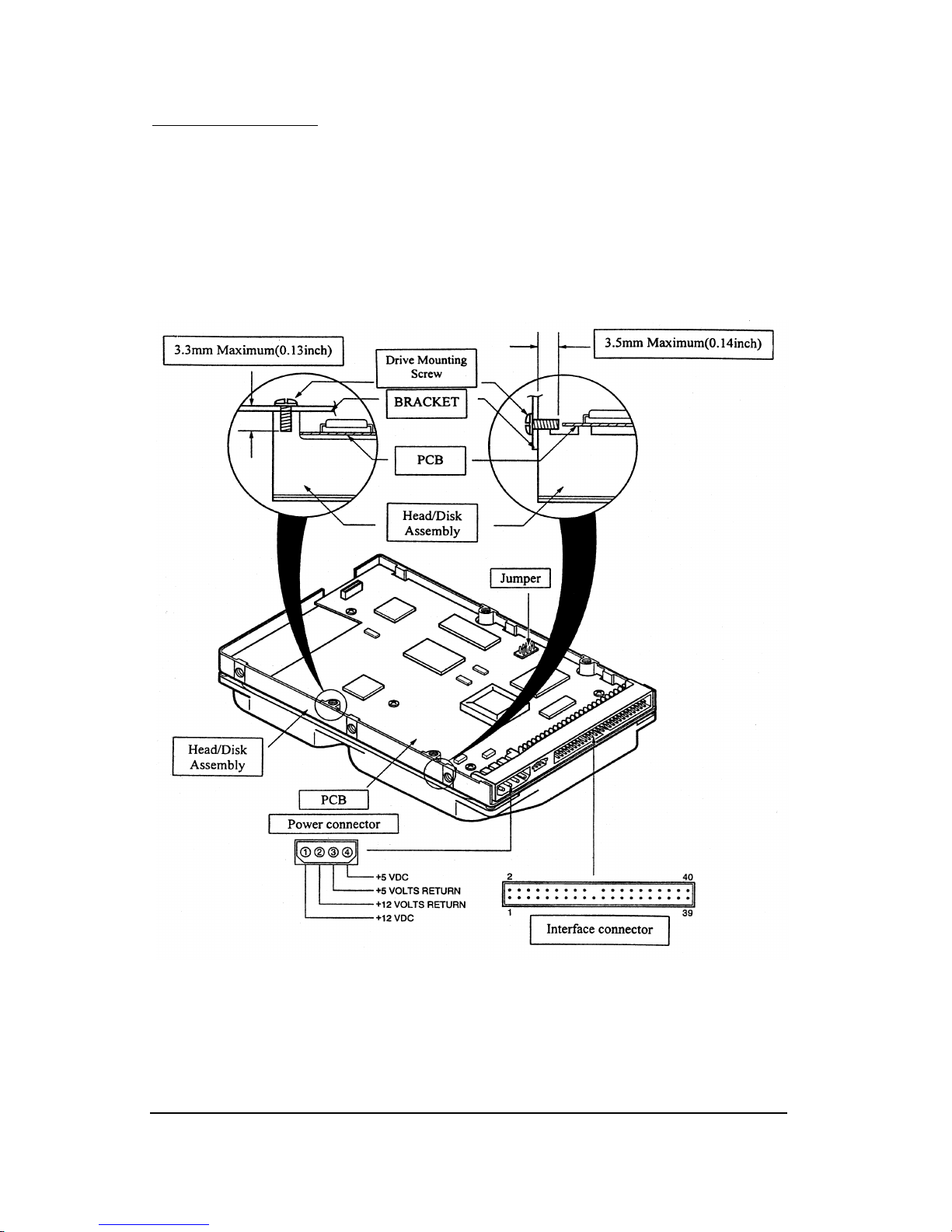
4-3-2 Clearance
The printed circuit board (PCB) is very close to the mounting holes. Do not exceed the
specified length for the mounting screw described in the Figure 4-3. The specified screw
length allows full use of the mounting-hole threads, while avoiding damage or placing
unwanted stress on the PCB.
Figure 4-3. Mounting-Screw Clearance
CAUTION : Using mounting screws that are longer than the maximum lengths
specified in Figure 4-3 voids the warranty on the Winner 3A WA31273A /
WA32543A / WA33203A / WA32163A / WA31083A, Winner 2A WA32162A.
Installation and Operation
WA31273A / WA32543A / WA33203A / WA32163A / WA31083A / WA32162A 4-5
4-3-3 Ventilation
The Winner 3A WA31273A / WA32543A / WA33203A / WA32163A / WA31083A,
Winner 2A WA32162A hard disk drive operates without a cooling fan, provided the
ambient air temperature does not exceed 55ºC. Any user-designed cabinet must provide
adequate air circulation to prevent exceeding the maximum temperature.
4-4 Cable Connectors
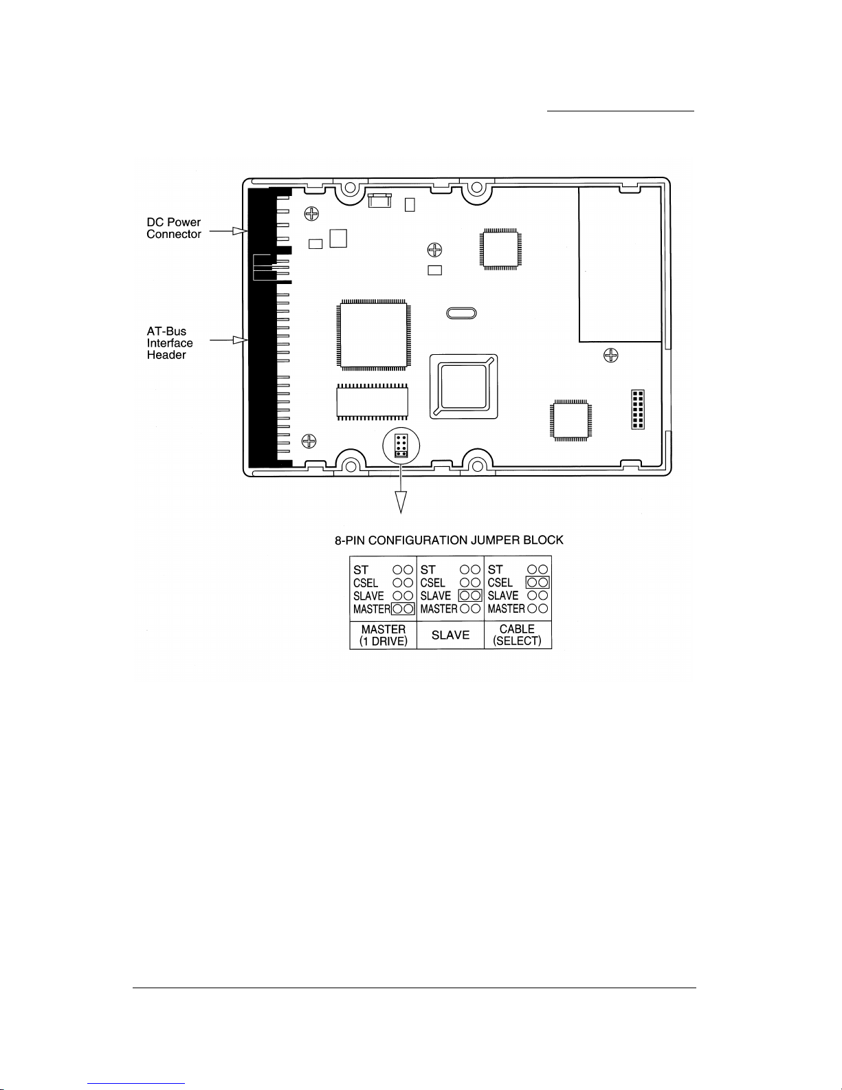
4-4-1 DC Power Connector(J7)
The drive’s DC power connector (J7) is mounted on the back edge of the Printed Circuit
Board (PCB) see to Figure 4-4. Table 4-1 lists the pin assignments.
Table 4-1. Power Connector (J7) Pin Assignment
PIN NUMBER POWER LINE DESIGNATION
1 +12V DC
2 +12V Return (Ground)
3 +5V Return (Ground)
4 +5V DC
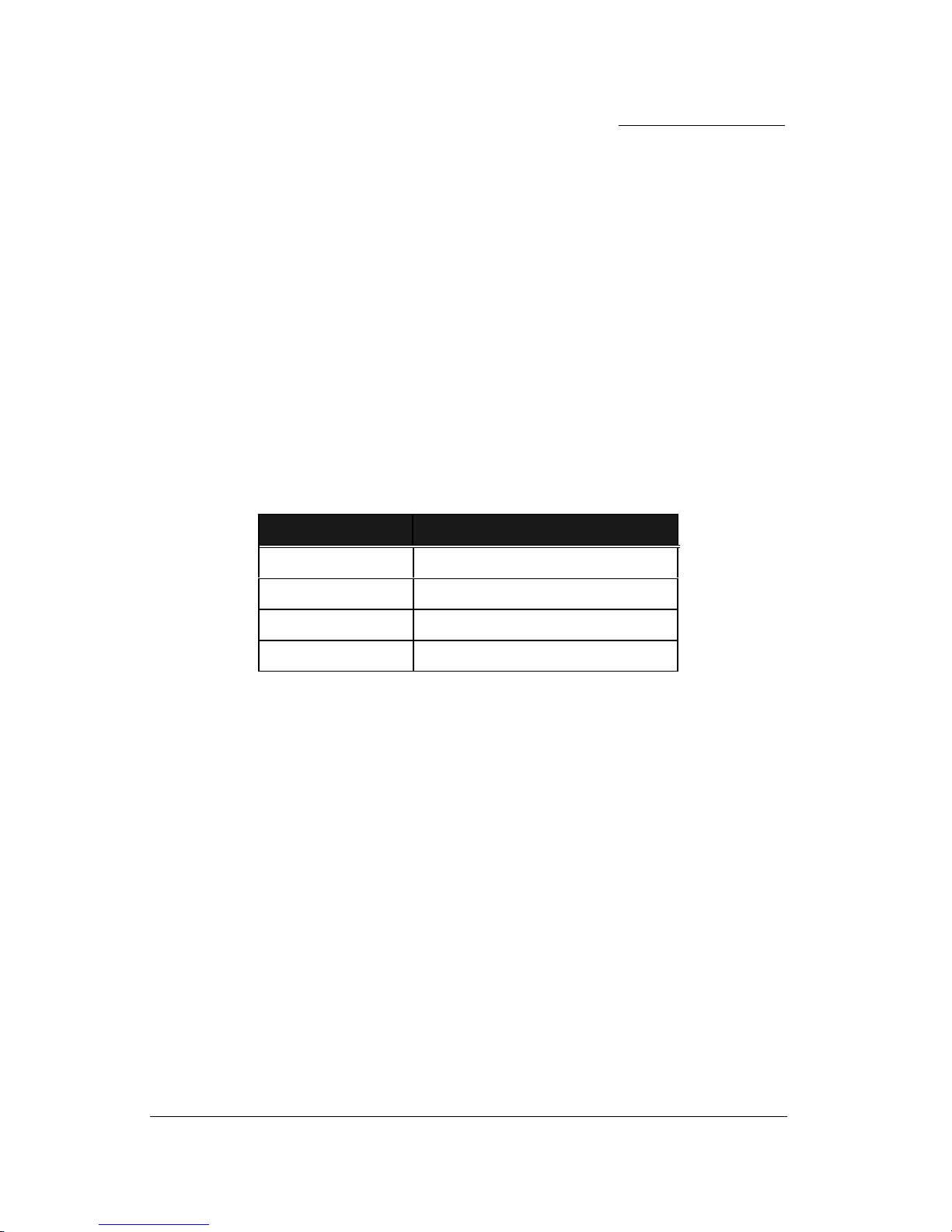
4-4-2 AT-Bus Interface Connector (J2)
The AT-Bus interface connector (J2) on the drive connects the drive to an adapter or an
on board AT adapter in the computer. J2 is a 40-pin Universal Header with two rows of
20 pins on 100-mil centers, as shown in Figure 4-4.
To prevent the possibility of incorrectly installing the I/F cable, the connector has been
keyed by the removal of Pin #20. The connecting cable is a 40-conductor flat ribbon
cable and the maximum cable length is 0.46m (18 inches).
For pin assignments and signal descriptions, see "AT INTERFACE and ATA
COMMANDS" in Chapter 6.
Installation and Operation
4-6 WA31273A / WA32543A / WA33203A / WA32163A / WA31083A / WA32162A
Figure 4-4. DC Power Connector (J7) and AT-Bus Connector (J2)
Installation and Operation
WA31273A / WA32543A / WA33203A / WA32163A / WA31083A / WA32162A 4-7
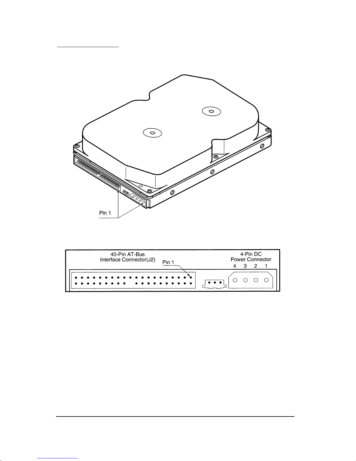
4-5 Configuration Jumpers(J5)
Jumper Definitions:
ST – Reserved for Manufacturing Test Process.
This jumper is used by Samsung engineers for development purpose
CSEL - Cable Select.
This jumper is used if Cable Select line is used for master and slave selection.
SLAVE - Slave Mode.
This jumper, when installed, is for configuring the drive in Slave Mode. Master jumper must be removed
when Slave Mode is configured.
MASTER - Master Mode
This jumper, when installed, is for configuring the drive in Master Mode. This jumper must be removed
when drive is configured in Slave Mode
Default Jumper Setting - Master Mode
Slave Jumper Setting - Slave Mode

Installation and Operation
4-8 WA31273A / WA32543A / WA33203A / WA32163A / WA31083A / WA32162A
4-5-1 Master and Slave Jumpers
You can daisy-chain two drives on the AT-Bus interface. When daisy-chaining two
drives, specify one drive as the Master, the other as the Slave by combination of master
and slave jumpers.
To configure a drive as the Master (Drive 0), install a jumper on the master pins.
Samsung ships the Winner 3A WA31273A / WA32543A / WA33203A / WA32163A /
WA31083A, Winner 2A WA32162A hard disk drives from the factory with the master
jumper installed (Drive 0), and slave Jumper opened.
To specify a drive as the Slave (Drive) remove the master jumper and install the jumper
on the slave pins.
NOTE: The order in which drives are connected in a daisy chain has no significance.
Installation and Operation
WA31273A / WA32543A / WA33203A / WA32163A / WA31083A / WA32162A 4-9
Figure 4-5. Jumper Pin Locations on the Drive PCB

Installation and Operation
4-10 WA31273A / WA32543A / WA33203A / WA32163A / WA31083A / WA32162A
4-5-2 Drive Installation
You can install the Winner 3A WA31273A / WA32543A / WA33203A / WA32163A /
WA31083A, Winner 2A WA32162A hard disk drive in an AT-compatible system in two
ways.
• To install the drive with a motherboard that contains a 40-pin AT-bus connector,
connect the drive to the motherboard using a 40-pin ribbon cable. Ensure that pin 1
of the drive is connected to pin 1 of the motherboard connector.
• To install the drive in a system without a 40-pin, AT-bus connector on its mother
board, you need an AT-bus adapter kit. The kit includes an adapter and a ribbon
cable, which is used to connect the board to the drive.
NOTE: Removing pin 20 of the drive ensures the connector cannot be installed upside
down.
Figure 4-6. indicates the cable and power cable connections required for proper drive
installation.
Figure 4-6. DC Power connector and AT-Bus Interface Cable Connections
Installation and Operation
WA31273A / WA32543A / WA33203A / WA32163A / WA31083A / WA32162A 4-11
4-6 System Startup Procedure
Once you have installed the Winner 3A WA31273A / WA32543A / WA33203A /
WA32163A / WA31083A, Winner 2A WA32162A hard disk drive and the adapter board
(if required) in your system, you can to partition and format the drive for operation. To
setup the drive correctly, follow these instructions:
(1) Power on the system.
(2) Run the SETUP program. Generally, you will find the SETUP program on a
Diagnostics or Utilities disk, or within the system's BIOS (Basic Input Output
System).
The SETUP program allows you to enter the types of optional hardware installed - such
as the hard disk drive type, the floppy disk drive capacity, and the display adapter type.
The system's BIOS uses this information to initialize the system when the power is
switched on for instructions on how to use the SETUP program, refer to the system
manual for your PC.
(3) Enter the appropriate parameters for the Winner 3A WA31273A / WA32543A /
WA33203A / WA32163A / WA31083A, Winner 2A WA32162A
During the AT system CMOS setup, you must enter the drive type for Winner 3A
WA31273A / WA32543A / WA33203A / WA32163A / WA31083A, Winner 2A
WA32162A the hard disk drives. This procedure allows the system to recognize the
drive by translating its physical drive geometry parameters such as cylinders, heads,
and sectors, into a logical addressing mode.
The following table shows the logical parameters that provide the maximum capacity on
Winner 3A WA31273A / WA32543A / WA33203A / WA32163A / WA31083A, Winner
2A WA32162A.
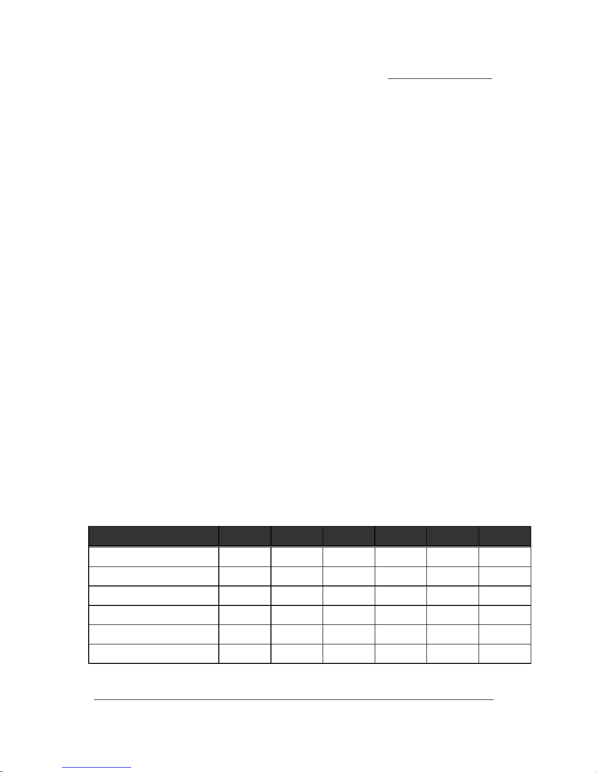
Table 4-3. Logical Drive Parameters
PARAMETER WA31273A WA32543A WA33203A WA32163A WA31083A WA32162A
Logical Cylinders 2480 4962 6202 4190 2094 4186
Logical Heads 16 16 16 16 16 16
Logical Sectors 63 63 63 63 63 63
Total Number Logical Sector
2,499,840 5,001,696 6,251,616 4,223,520 2,110,752 4,219,488
CMOS Setup 1279 MB 2560 MB 3200 MB 2162 MB 1081 MB 2160 MB
Formatted Capacity 1279 MB 2560 MB 3200 MB 2162 MB 1081 MB 2160 MB

Installation and Operation
4-12 WA31273A / WA32543A / WA33203A / WA32163A / WA31083A / WA32162A
If the drive types offered by the CMOS do not support the number of cylinders, heads
and sectors shown in the table and your system does not support a "user-defined" drive
type, select a drive type whose total number of sectors* are less than or equal to the
number of data sectors of the Winner 3A WA31273A / WA32543A / WA33203A /
WA32163A / WA31083A, Winner 2A WA32162A.
NOTES : * The total numbers of sectors are calculated by (CylindersxHeadsxSectors)
of the selected drive type.
See configuration jumper part (4.5) of this manual.
(4) Save the set-up parameters and re-boot the system using the operating system
installation disk, for example, MS-DOS, then follow the installation instructions in
your operating system manual.
If you are using MS-DOS:
(1) Run the FDISK utility or a third-party partitioning program.
NOTE : When using DOS version 3.2 or below, the DOS partitions only 32 Mbytes of the
drive's capacity. DOS 3.3 partitions the drive in multiples of 32 Mbytes. DOS
4.01 or later, or a third-party partitioning program, create partitions that exceed
32 Mbytes.
(2) To format the hard drive and transfer the operating system to the drive, type ;
FORMAT C:/S
After this command executes, boot the system from the hard drive.
NOTE : A low-level format is not required as this was done at the factory before
shipment.

WA31273A / WA32543A / WA33203A / WA32163A / WA31083A / WA32162A 5-1
Chapter 5
DISK DRIVE OPERATION
This chapter describes the operation of the Winner 3A WA31273A / WA32543A / WA33203A /
WA32163A / WA31083A, Winner 2A WA32162A functional subsystems. It is intended as a
guide to the operation of the drive, rather than a detailed theory of operation.
5-1 Drive Mechanism
This section describes the mechanism of the drive. the Winner 3A WA31273A / WA32543A /
WA33203A / WA32163A / WA31083A, Winner 2A WA32162A hard disk drive consists of a
mechanical sub-assembly and a printed circuit board assembly (PCBA) as shown in figure 5-
1.
5-1-1 Head Disk Assembly
The head/disk assembly (HDA) contains the mechanical sub-assemblies of the drive, which
are sealed between the aluminum-alloy base and cover. The HDA consists of the disk stack
assembly, rotary positioner assembly, head stack assembly, actuator latch assembly, and
base casting which includes the DC motor assembly. HDA assembly is done in a Class 100
clean room. These subassemblies cannot be adjusted or field repaired.
CAUTION: To avoid contamination in the HDA, never remove or adjust its cover and seals
Disassembling the HDA voids your warranty.
The Winner 3A WA31273A / WA32543A / WA33203A / WA32163A / WA31083A, Winner 2A
WA32162A products are part of a one, two and three disk product family. The Winner 3A
WA31273A / WA31083A contains one magnetic disk and two read/write heads and uses
both sides of the magnetic disk. The Winner 3A WA32543A / WA32163A, Winner 2A
WA32162A have two magnetic disks and four read/write heads, and the Winner 3A
WA33203A has three magnetic disks and five read/write heads.
5-1-2 Base Casting Assembly
A one piece, aluminum-alloy base casting provides a mounting surface for the drive
mechanisms and PCBA. The base casting also plays the role as the flange for the DC spindle
motor assembly. A gasket provides a seal between the base and cover castings that enclose
the drive mechanism.

Disk Drive Operation
5-2 WA31273A / WA32543A / WA33203A / WA32163A / WA31083A /
5-1-3 Spindle Motor Assembly
The spindle motor assembly consists of a brushless three-phase motor, spindle bearing
assembly, disk mounting hub, and a labyrinth mechanical seal. The entire spindle motor
assembly is completely enclosed in the HDA and screwed to the base casting. The labyrinth
seal prevents bearing lubricant from coming out into the HDA. The motor rotates the
spindle shaft at 5400(Winner 3A) rpm and 4500(Winner 2A) rpm.
Figure 5-1. Exploded Mechanical view

Disk Drive Operation
WA31273A / WA32543A / WA33203A / WA32163A / WA31083A / WA32162A5-3
5-1-4 Disk Stack Assembly
The disk stack assembly in the Winner 3A WA31273A / WA32543A / WA33203A / WA32163A /
WA31083A, Winner 2A WA32162A hard disk drive consists of 1, 2 or 3 disks and disk spacers
secured on the hub of the Spindle Motor Assembly by a disk clamp. The aluminum-alloy
disks have a sputtered thin-film magnetic coating.
A carbon overcoat protects the disk magnetic surfaces to prevent head and media wear due
to head contact with the disk surfaces during head take-off and landing. Head contact with
the disk surface occurs only in the landing zone outside of the data area, when the disks are
not rotating at full speed. The landing zone is located at the inner diameter of the disk, far
beyond the last cylinder of the data area.
5-1-5 Head Stack Assembly
The head stack assembly consists of an actuator/coil sub-assembly, read/write heads, a
flexible printed circuit and bearings. The actuator/coil sub-assembly is assembled with
actuator and over molded coil. Read/write heads are mounted to spring-stainless steel
flexures that are then swage mounted onto the rotary positioning assembly arms of the
actuator.
The flexible circuit connects the read/write heads with the PCBA via a connector through
the base casting. The flexible circuit contains a read/write Preamplifier IC.
5-1-6 Rotary Positioning Assembly
The rotary positioner, or rotary voice coil motor, is a SAMSUNG proprietary design that
consists of upper and lower permanent magnetic yokes fixed to the base casting and a
rotary overmolded coil on the head stack assembly. The magnet consists of two alternating
poles glued to the magnet yoke. Rubber crash stops mounted on the upper magnet yoke
and base casting prevent the head from being flown into the spindle or off of the disk
surface.
Current from the power amplifier induces a magnetic field in the voice coil. Fluctuations in
the field around the permanent magnets move the voice coil so that heads can be positioned
on the requested cylinder.
5-1-7 Air Filtration System
It is very important that air circulating within the drive be free of particles. SAMSUNG HDA’s
(head/disk assemblies) are assembled in a Class 100 purified air environment to ensure cleanliness. To
retain this clean air circulation, the Winner 3A WA31273A / WA32543A / WA33203A / WA32163A /
WA31083A, Winner 2A WA32162A is equipped with a recirculating filter, which cleans the air within
the HDA. The recirculating filter traps any particles which may be generated during head landing or
 Loading...