

Samsung W0690, AW1090, AW0790, AW1290, AW0890 Service Manual
...
ROOM AIR CONDITIONER
AW0690
AW0790
AW0890
AW1090
AW1290
AW1890
Manual
SERVICE
AIR CONDITIONER CONTENTS
1. Precautions
2. Product Specifications
3. Installation and Operating
Instructions
4. Disassembly and Reassembly
5. Troubleshooting
6. Exploded Views and Parts List
7. Block Diagram
8. PCB Diagram
9. Wiring Diagrams
1. Precautions
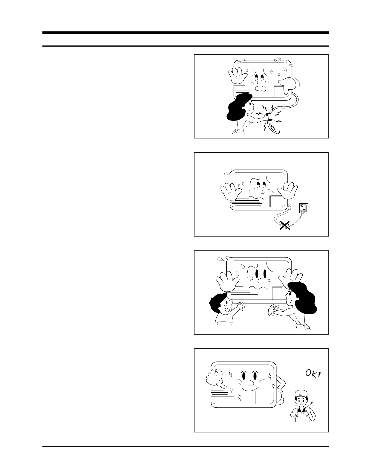
1. Warning: Prior to repair, disconnect the
power cord from the circuit breaker.
2. Use proper parts: Use only exact
replacement parts. (Also, we recommend
replacing parts rather than repairing them.)
3. Use the proper tools: Use the proper tools
and test equipment, and know how to use
equipment may cause problems laterintermittent contact, for example.
4. Power Cord: Prior to repair, check the
power cord and replace it if necessary.
5. Avoid using an extension cord, and avoid
tapping into a power cord. This practice
may result in malfunction or fire.
6. After completing repairs and reassembly,
check the insulation resistance, Procedure:
Prior to applying power, measure the
resistance between the power cord and the
ground terminal. The resistance must be
greater than 30 megohms.
Fig. 1-1 Avoid Dangerous Contact
Fig. 1-2 No Tapping and No Extension Cords
7. Make sure that the grounds are adequate.
8. Make sure that the installation conditions
are satisfactory. Relocate the unit if
necessary.
9. Keep children away from the unit while it is
being repaired.
10. Be sure to clean the unit and its surrounding
area.
Fig. 1-3 No Kids Nearby!
Samsung Electronics 1-1
Fig. 1-4 Clean the Unit

MEMO
1-2 Samsung Electronics
2. Product Specifications
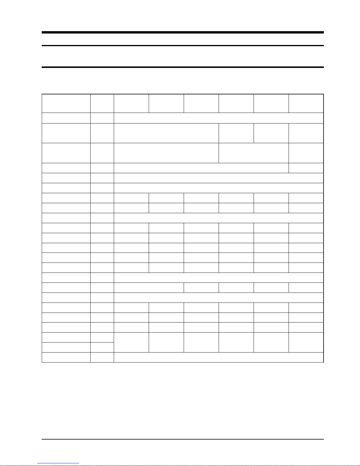
2-1 Table
Item
Type
Dimensions:
(Width X Height X Depth)
Packing Size
X Height X Depth)
(Width
Voltage:
Phase
Frequency
Operating Current
Power Consumption
Refrigerant Type
Refrigerant Charge
Cooling Capacity
EER
Net Weight
Condenser
Condenser Fan
Evaporator
Evaporator Fan
Fan Motor
Compressor
Overload Protect
Compressor Capacitor
Fan Motor Capacitor
Fan Speed Control
Unit of
Measure
-
mm (inch)
mm (inch)
Volt
-
Hz
A
W
FREON
g
BTU/h
BTU/HW
kg
Row x Col
Type
Row x Col
Type
-
-
µF/ VAC
µF/ VAC
-
AW0690 AW0790 AW0890 AW1090 AW1290 AW1890
Window
5.6
600
380
6,000
10.0
29
2 x 15
2 x 14
IC-9630SWD6C
44A062HS1EB
MRA12040-12008
30/5µF 370VAC
(Dual Type)
520 x 345 x 485
571 x 454 x 546
6.7
715
470
7,000
9.8
29
3 x 15
IC-9630SWD6E
44A072HW1EB
MRA98706-12008
25/5µF 370VAC
(Dual Type)
115V
Single
7.4
800
R-22
500
8,000
10.0
29
3 x 15
Propeller-Fan
3 x 14
Blower
IC-9630SWD6E
44080HS1EB
MRA12083-12008
35/6µF 370VAC
(Dual Type)
HIGH, MID, LOW
600 x 394 x 595
60
9.2
1,000
600
10,000
10.0
45
3 x 17
2 x 14
AFS090ZREA
44B102HS1EF
MRA12109-12007
40/15µF 370VAC
(Dual Type)
600 x 395 x 595
728 x 459 x 647
12.0
1,330
800
12,000
9.0
45
3 x 14
2 x 14
AMAFS-100ZREB
44B124HW1EG(4)
MRA98693-12007
40/15µF 370VAC
(Dual Type)
660 x 425 x 730
723 x 555 x 798
230/208V
1,800/1,750
18,000/17,500
10.0/10.0
AFS140ZTEA
48B175IV1EH
MRA12107-12007
35/6µF 450VAC
(Dual Type)
8.5/9.1
1,090
61
3 x 16
3 x 15
Samsung Electronics 2-1
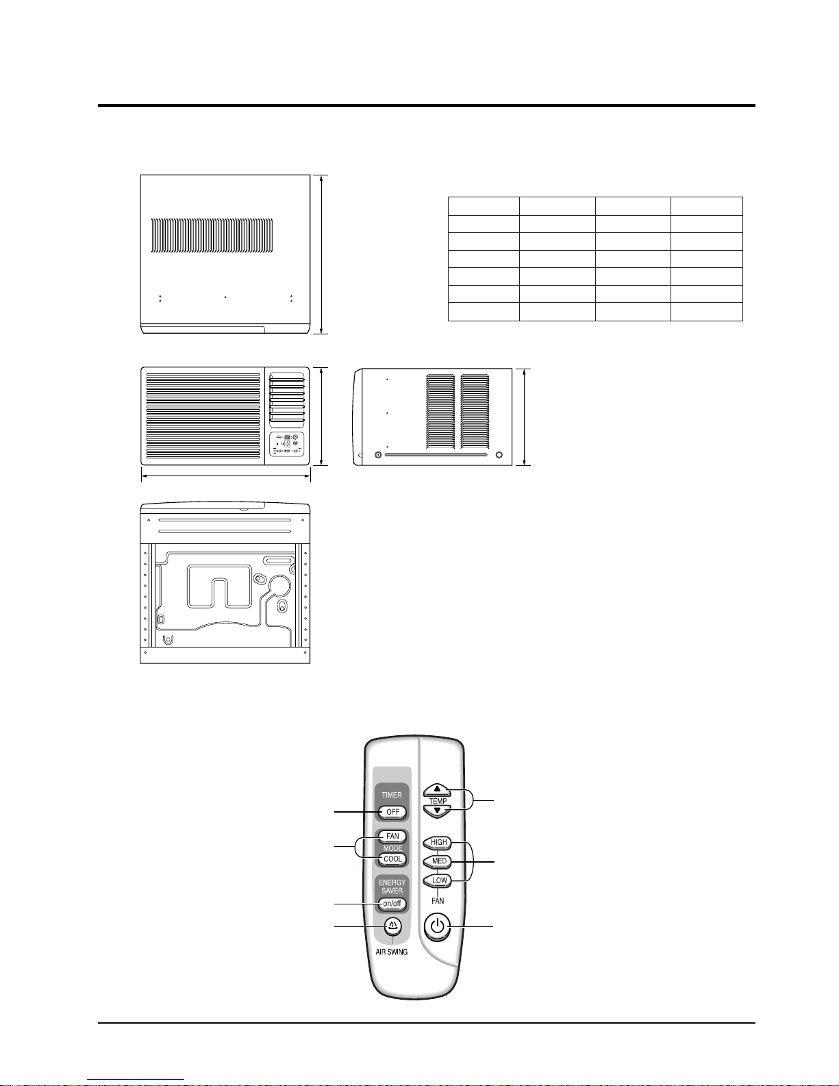
2-2 Dimensions
W
H
H
D
2-2-1 Main Unit
Model
AW0690
AW0790
AW0890
AW1090
AW1290
AW1890
W
520
520
520
600
600
660
345
345
345
394
395
425
Unit : mm
H
D
485
485
485
595
595
730
Front view
2-2-2 Remote Control
Side view
Timer button
FAN/COOL mode
selection buttons
Energy saver button
Air Swing button
2-2 Samsung Electronics
Temperature adjustment
buttons
Fan speed adjustment
buttons
On/Off button
3. Installation and Operating Instructions
3-1 Installation
When selecting the area for installing the unit, be sure to obtain approval of the customer.
*
1. Make sure that you install the unit in an area that
provides good ventilation.
The air conditioner must not be blocked by any
obstacle affecting the air flow near the air inlet and
air outlet.
2. Make sure that you install the unit in an area which
can endure the weight and vibration of the unit.
3. Make sure that you install the unit away from heat
or vapor.
4. Make sure that you install the unit in an area where
the cooled air can be evenly spread in a room.
5. Make sure that you install the unit in an area away
from TVs, audio units, cordless phones, fluorescent
lighting fixtures and other electrical appliances.
(obtain a clearance of at least one meter)
6. Make sure that you install the unit in an area which
provides easy drainage for condensed water.
7. Make sure that you install the unit in an area not
exposed to rain or direct sunlight.
(Install a separate sunblind if exposed to direct sun-
light.)
8. Do not install the unit in an area subjected to noise
or vibration amplification which may affect your
neighbor.
(Fix the unit firmly if mounted in a high place.)
Caution:
Do not use the air conditioner in such areas as a greasy area(including machine oil),
saline area(sea side), or sulphuric area(hot spring). When using the air conditioner in these areas, special maintenance is
required. Contact your local dealer or our service center for advice.
Samsung Electronics 3-1
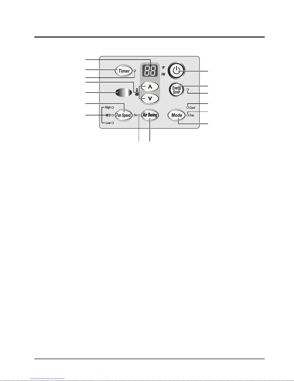
3-2 Function Description
Temperature/
Timer settings
Timer button
Timer indicator
Temperature
adjustment buttons
Remote Control
Sensor
Fan speed
adjustment button
Fan speed indicator
On/Off button
Energy saver button
Energy saver indicator
Cool indicator
Fan indicator
Operation mode
selection button
Swing indicator
Air Swing button
3-2-1 Cooling operation mode
The compressor is turned on and off according to the ambient temperature and set temperature.
1. Compressor on and off control
• Compressor on and off control according to the ambient temperature.
The compressor is turned off when "ambient temperature = set temperature "
*
The compressor is turned on when "ambient temperature = set temperature +1˚C"
*
2. Default value after power reset ➔set temperature = 18˚C, 75˚F
FAN SPEED = HIGH
3. Set temperature indicating (setting) range : 1˚C interval from 18˚C to 30˚C.
1˚F interval from 64˚F to 86˚F.
3-2-2 Fan operation mode
1. If "Fan operation mode" signal is received from remocon.
➔ the compressor is immediately turned off and only fan motor is operated at set blowing speed.
➔ it changes such as "HIGH ➔MED ➔ LOW"( if Fan speed is selected).
2. The initial FAN speed is set to "HIGH".
3. The set temperature can not be indicated and set.
3-2-3 Energy Saver Operation
● If the compressor turn off at the cooling operation, the fan motor turn off after operating during the fixation time only,
and operation that save energy by turn off the fan motor continuously before the condition of the compressor on.
● The fan motor is not operated at flow wind operation.
1. Energy Saver operation specification at the cooling operation
1) Fan motor control in compressor on : operate with setting wind speed
2) Fan motor control in compressor off : After compressor off, the fan motor is operated breeze for 2 minutes and then it
3) After the fan motor off, the compressor and fan motor is operated normally when the compressor on.
3-2 Samsung Electronics
turn off.
3-2-4 LED display indication in case of error detection
Installation and Operating Instructions
ERROR OPERATION
ROOM THERMISTOR
(OPEN OR SHORT)
7-SEG
LED DISPLAY (LE01)
E1 displayed
1. Set operation in case of error occurrence.
• Malfunction of each temperature sensor (open, short)
- Error mode display, warning sound.
- The operation status is off.
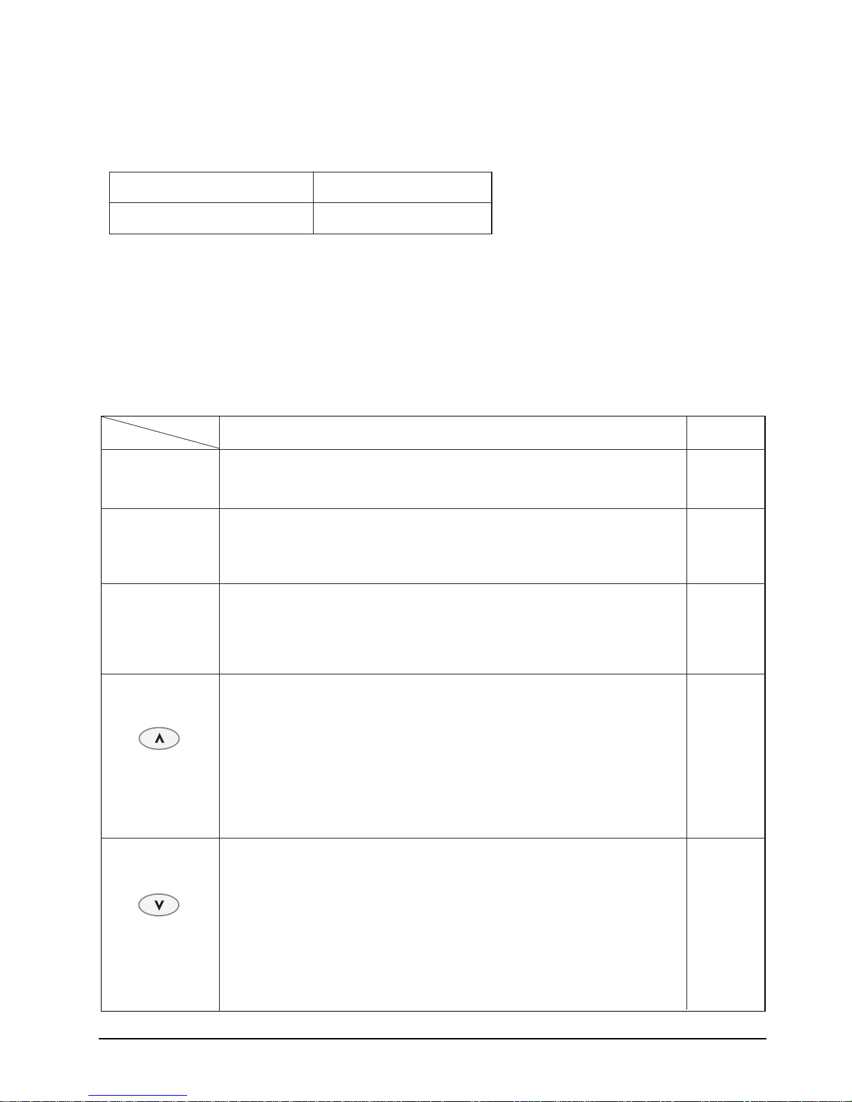
3-2-5 Panel key operation
Key description
Key name
Operation/Stop • Start and stop of operation
- Once ON=start of operation, again ON=stop of operation TACT
- No operation continuously.
Function selection • Change of the operation mode(in case of the model option cooling only)
- It is selected with "COOL →FAN"(default=COOL) for each once turn on. TACT
- In case that the operation off, it is treated invalidity.
- No operation continuously.
Key operational function Key Type
Flow wind selection • Set the fan motor speed
- It is selected with
"HIGH → MED → LOW → HIGH" for each once turn on. TACT
- In case that the operation off, it is treated invalidity.
- No operation continuously.
Temperature • It is increased the desired temperature that displayed now.
adjustment - The desired temperature is increased for each pressing with 1°… unit.
(increase) (Increase:18˚C →19˚C → .. → 21˚C → .. → 23˚C → .. → 29˚C → 30˚C
64˚F → 65˚F → .. → 70˚F → .. → 80˚F → .. → 85˚F → 86˚F)
- In case that the desired temperature is 30˚C, 86˚F…, if the
"increase key is pressed, it is not increased. TACT
If you press the "Increase/Decrease" key of the remote controller,
it occurs the alarm horn at above status.
- It is possible a single shot and continue operation.
- In case of the operation off and flow wind operation, it is treated invalidity.
Temperature • It is decreased the desired temperature that displayed now.
adjustment - The desired temperature is decreased for each pressing with 1˚... unit.
(decrease) (Decrease:30˚C →29˚C → .. → 23˚C → .. → 21˚C → .. → 19˚C → 18˚C
86˚F → 85˚F → .. → 80˚F → .. → 70˚F → .. → 65˚F → 64˚F)
- In case that the desired temperature is 18˚C, 64˚F…, if the
"decrease key is pressed, it is not decreased. TACT
If you press the "Increase/Decrease" key of the remote controller, it occurs the alarm
horn at above status.
- t is possible a single shot and continue operation.
- In case of the operation off and flow wind operation, it is treated invalidity.
Samsung Electronics 3-3
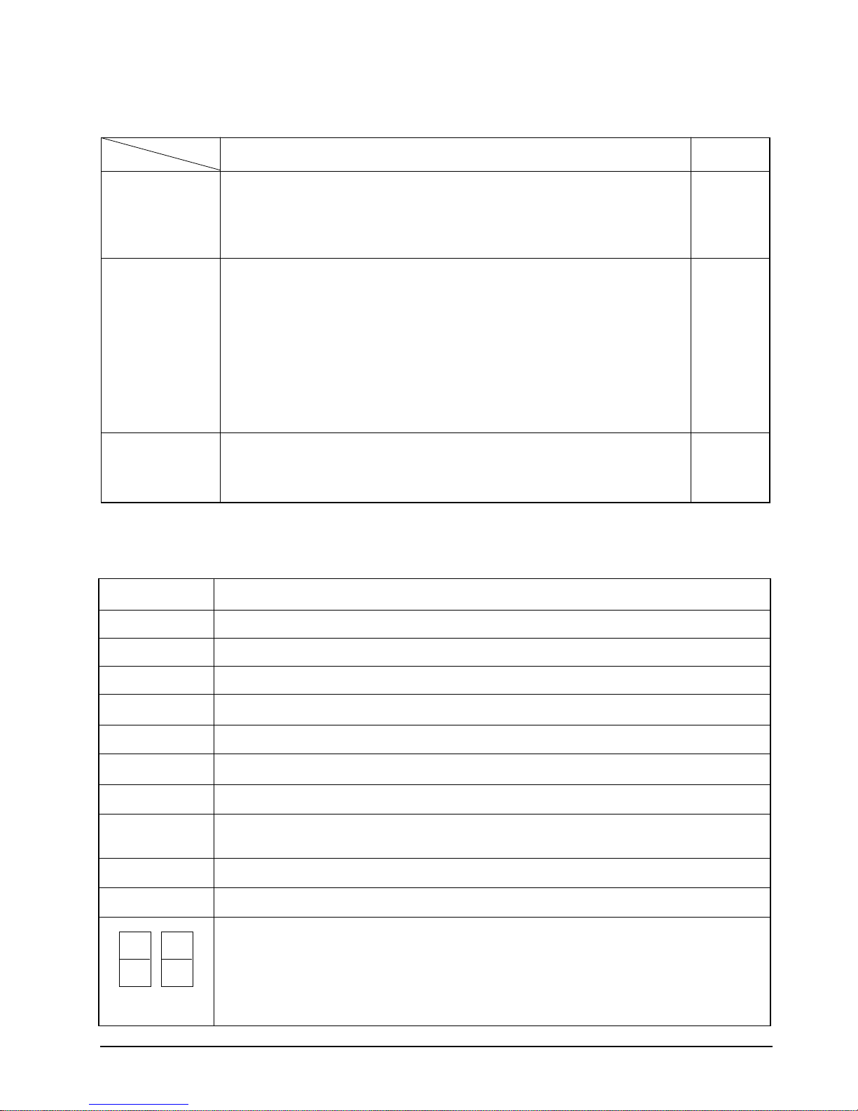
Installation and Operating Instructions
Key description
Key name
Left/right swing Operation and stop of the left/right swing
- Once key on=left/right swing on, key on=left/right swing off again
- No operation continuously. TACT
- In case that the fan motor off(saving energy operation), left/right swing motor is not
operated(It is cleared in fan motor on.)
Off timer Setting the OFF Timer.
- In status of non-reservation, stand by the reservation set for once when key on. : "--" display
In status of the reservation setting stand by, it is not turn on the key within 10 second,
the reservation is cleared.
- In status of the reservation setting stand by within 10 second, the reservation setting time
is increased when key on.( -- →1Hr →2Hr → .. → 23Hr → 24Hr)
After setting the reservation time, if it is not turn on the key within 10 second,
it is reserved the Off timer with setting reservation time.
- For 24Hr, stand by the reservation set for once when key on. : "--" display
- It is possible a single shot and continue operation.
- In case of the operation off, it is treated invalidity.
Energy Save Operation and stop of the saving energy operation
- Once key on=saving operation on, key on=saving energy off again
- No operation continuously
- In case of the operation off, it is treated invalidity.
Key operational function Key Type
3-2-6 LED lamp operation specifications
TACT
TACT
LAMP name Operations specifications
COOL The mode is set to "COOL
FAN The mode is set to "FAN
˚C The set temperature is displayed Others→OFF
HIGH The mode is set to "HIGH
MID The mode is set to "MID
LOW The mode is set to "LOW
AIR SWING During setting of the "SWINGMODE
Hr During setting of the convenient reserve (OFFTIMER) time →blinking
After setting of the convenient reserve (OFF TIMER) time →ON Others→OFF
TIMER Stand for /during / After setting of Convenient reserve (OFFTIMER) time→ON Others→OFF
ENERGY SAVER Energy Saving operation→ON Others → ON
In case of (set) temperature display
NO. (1) 7 seg. LED display indicates temperature of the tens digit
→
NO. (2) 7 seg. LED display indicates temperature of the units digit
→
In case of time (OFF TIMER) display
NO. (1) 7 seg. LED display indicates time of the tens digit
(1) (2)
→
NO. (2) 7 seg. LED display indicates time of the units digit
→
ON Others→OFF
" →
ON Others→OFF
" →
ON Others→OFF
" →
ON Others→OFF
" →
ON Others→OFF
" →
" is set to "
SWING
ON Others→OFF
" →
3-4 Samsung Electronics
4. Disassembly and Reassembly
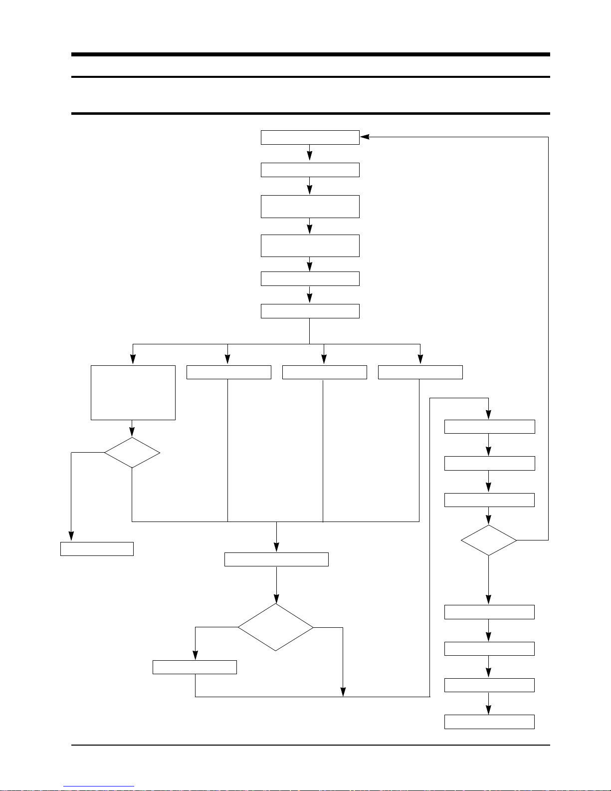
4-1 Compressor Replacement Flow Chart
Locate cause of defect
Release refrigerant
Disconnect electrical wiring from
Cut refrigerant lines
from compressor
Plug disconnected lines
Replace compressor
compressor
Inspect electrical
wiring for defects,
and terminals for
correct and secure
connections
Problem?
Y N
Corrective action
Solder discharge line
Check refrigerant oil level
Low oil level?
Solder suction line Use nitrogen gas
NY
Perform soldering function
Fill system with nitrogen gas
Check for leakage
Y
Leakage?
N
Release nitrogen gas?
Evacuate system
Add oil as necessary
Samsung Electronics 4-1
Recharge system
Recharge system
4-2 Checking the oil
Fill the transparent container with 10cc of oil, and then conduct the test.
4-2-1 Oil quality
Refrigerant Cycle
Normal
Over-heated
Compressor damage
Color
Light Yellow
Brown
Dark brown
Oil Condition
Odor
No Odor
-
4-2-2 Replacing and refilling the refrigerant oil
1. Replacing the compressor - Do not fill the system with oil as the compressor is already charged.
2. Replacing the condenser - Refill 50cc.
3. Replacing the evaporator - Refill 50cc.
4. Replacing the refrigerant - Refill 30cc.
5. The high pressure side is filled up with oil after the vacuum is completed.
6. When the refrigerant leaks, it is generally not necessary to refill the oil if the leakage is not severe.
Remarks
Return with the system
Oil Change
Oil Change
4-2 Samsung Electronics
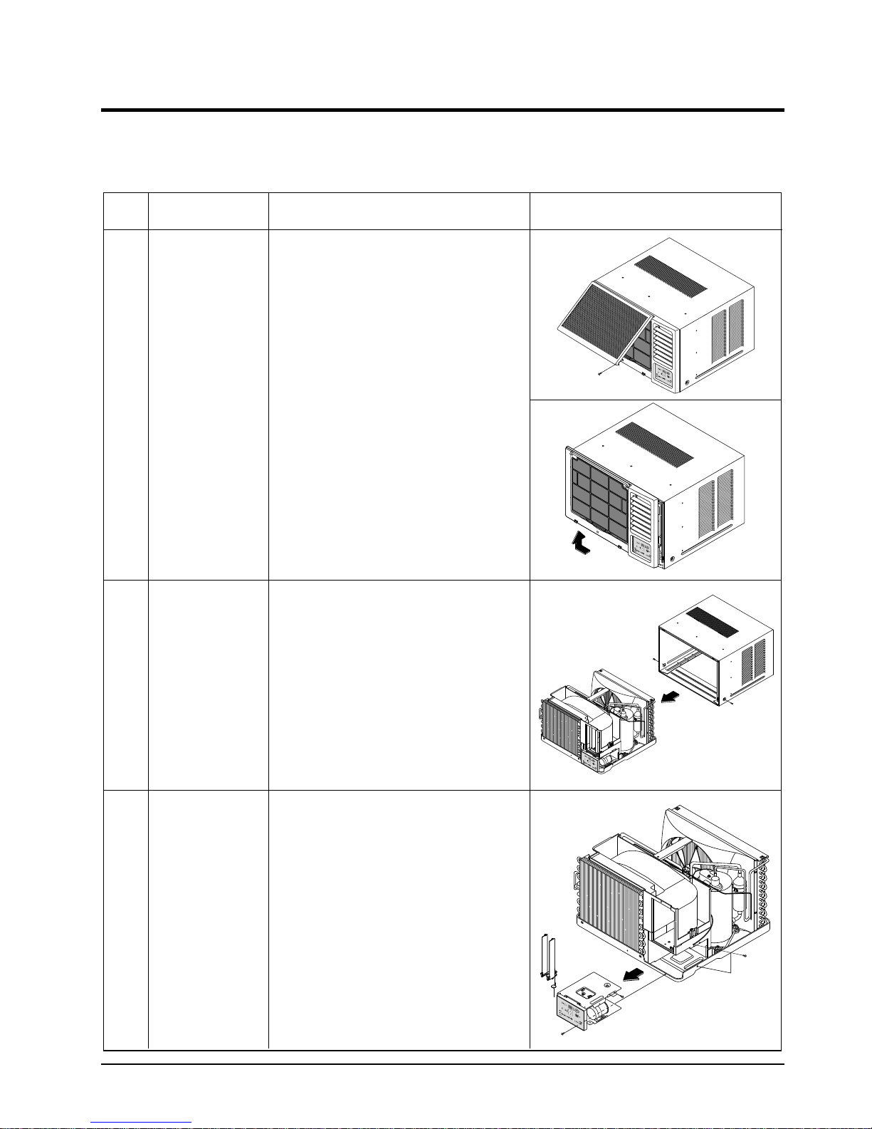
4-3 Disassembly and Reassembly Procedure
4-3-1 AW0690/AW0790/AW0890
Stop operating the air conditioner, and pull out the power cord before repair.
No. Part name Procedures Remarks
①
➁
Ass'y Grill
Ass'y Cabinet
1. Pull the panel front and remove the screw on
the grille
2. Push the grille left side and pull up
1. Remove the two screws both side cabinet.
2. Pull the front both side, and remove the unit
from the cabinet.
➂
Ass'y Control
1. Remove the blade V and arm blade
2. Remove 2 screws, and 2 earth wire screws.
3. Remove two lead wire assemblies.
4. Take out the control box forward.
Samsung Electronics 4-3
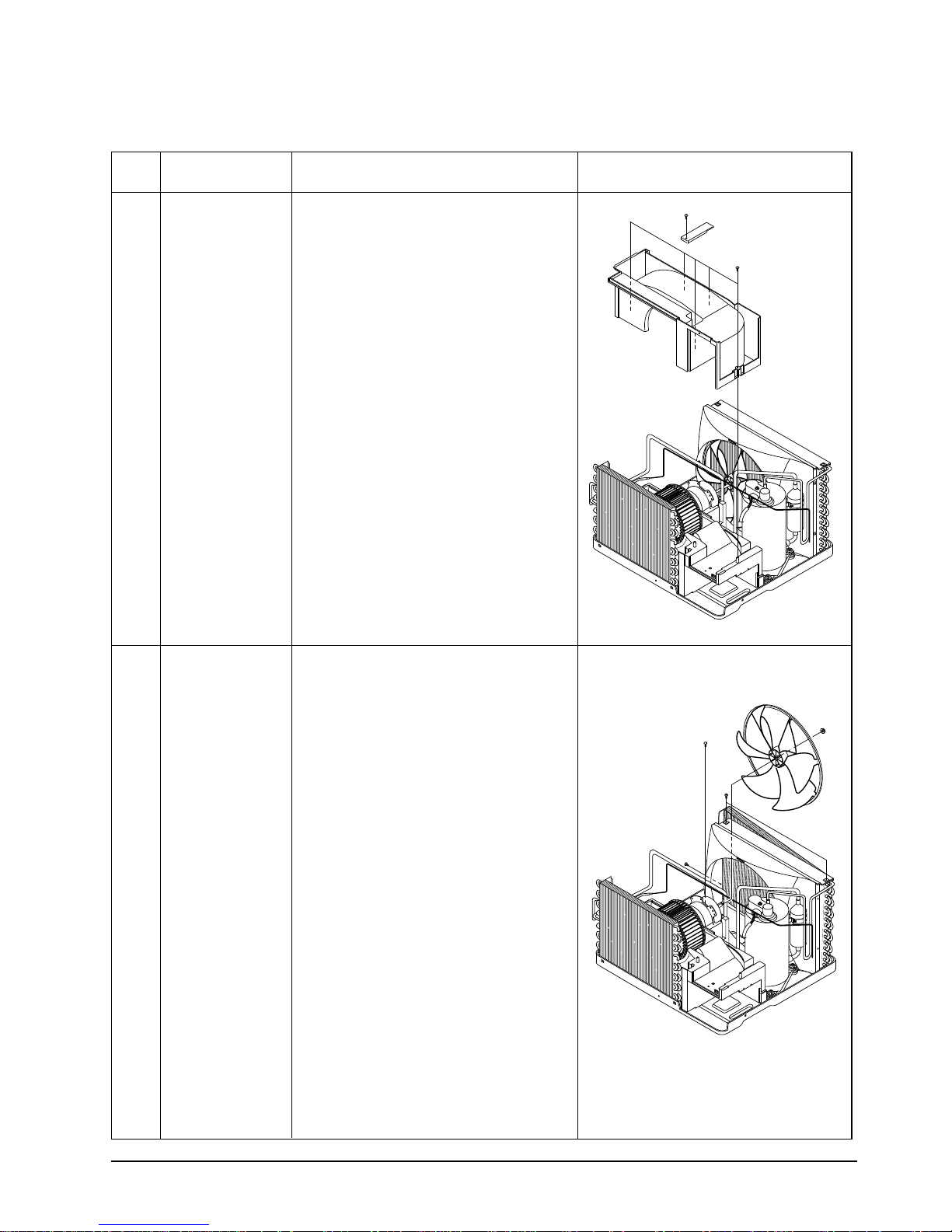
Disassembly and Reassembly
No. Part name Procedures Remarks
➃
Frame Up
1. Remove 6 screws on the Frame up
and remove the Frame up and the reinf from
case cond.
➄
Case Cond &
Propeller Fan
1. Remove two screws on the bottom side, and
4 screws on the case cond.
2. Pull up the case cond and separate the cond
case from the cond.
3. Remove the nut flange, and remove the propeller fan
4-4 Samsung Electronics

Disassembly and Reassembly
No. Part name Procedures Remarks
➅
Cond Casing
1. Remove the cond casing
➆
Blower & Motor
1. Move the motor & blower toward the
evap, and lift up the motor & blower from
the frame low.
Samsung Electronics 4-5
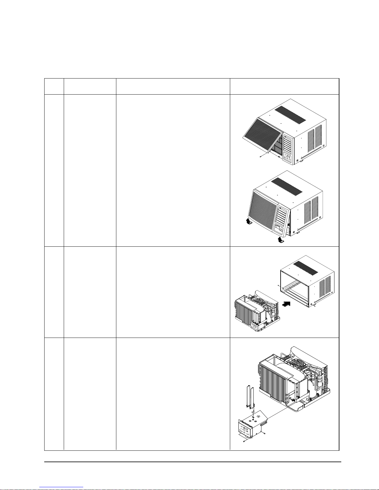
4-3-2 AW1090/AW1290
Stop operating the air conditioner, and pull out the power cord before repair.
No. Part name Procedures Remarks
①
➁
Ass'y Grill
Ass'y Cabinet
1. Pull the panel front and remove the screw on
the grille
2. Hold the lower part of the grill with two hands
while pressing down on both sides of the
lower part of the cabinet, pull it forward by
about 30, and then lift it up for removal.
3. Pull out the Seal-cabi front between Base pan
can Cabinet
1. Remove the screws on both sides of the
cabinet to disconnect the cabinet and frame.
2. Pull the handle on the front side of the
bottom, and remove the unit from the
cabinet.
➂
Ass'y Control
1. Remove 6 screws,
2. Remove three lead wire assemblies.
3. Remove the blade V and arm blade.
4. Take out the control box forward.
4-6 Samsung Electronics
and earth wire screw.
 Loading...