

Page 1
Samsung Electronics 4-1
4. Disassembly and Reassembly
4-1 Cabinet and PCB
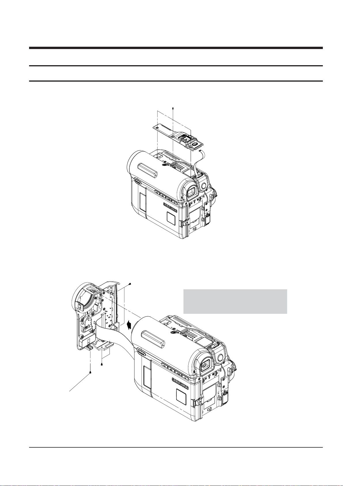
4-1-1 Ass’y Zoom Removal
ΠREMOVE 3 SCREWS
(M 1.7 X 4 BLK)
Fig. 4-1 Ass’y Zoom Removal
4-1-2 Ass’y Front Removal
Fig. 4-2 Ass’y Front Removal
ΠREMOVE 2 SCREWS
(M1.7 X 4 BLK)
´ REMOVE
2 SCREWS
(M1.7 X 4 BLK)
ˇ REMOVE 1 SCREW
(M1.7 X 5 WHT)
Caution : Please indicate that the connector
must be detached before separating
the Front Assembly
Page 2
4-2
Disassembly and Reassembly
Samsung Electronics
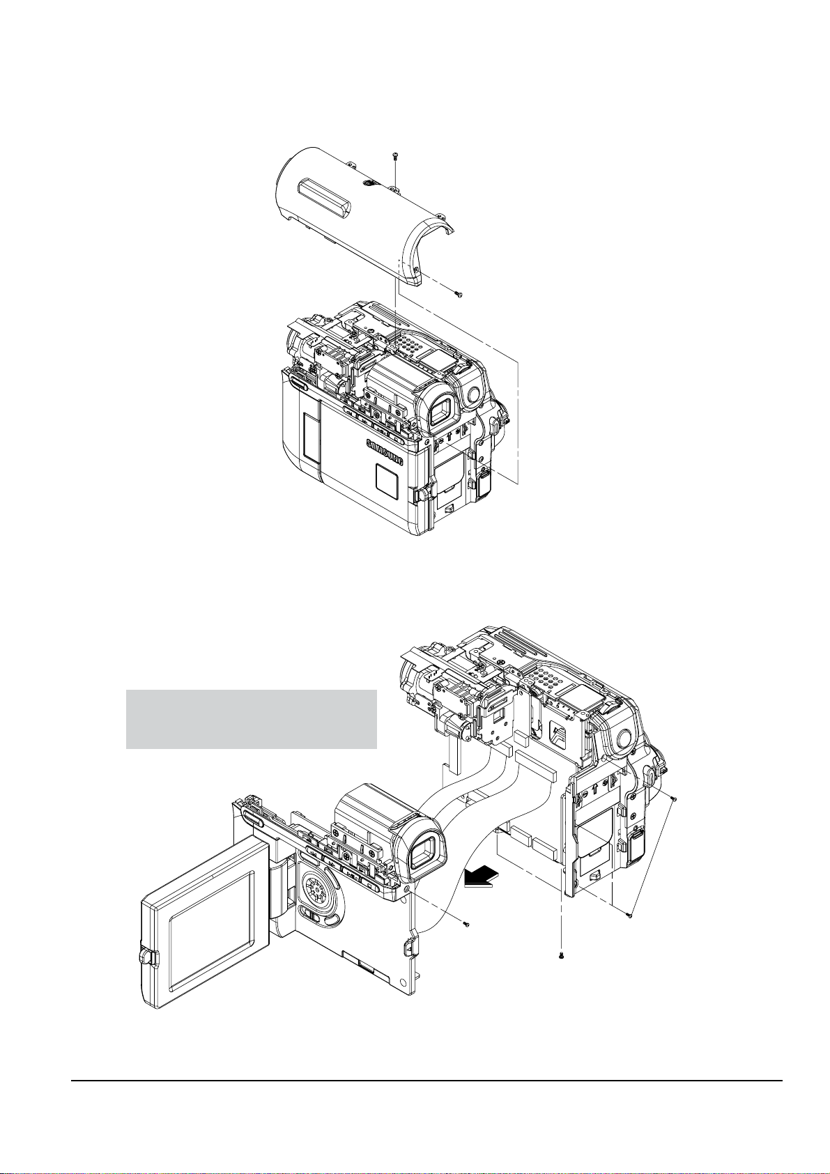
Fig. 4-4 Ass’y Left Removal
4-1-3 Ass’y Top Removal
ΠREMOVE 1 SCREW
(M1.7 X 4 BLK)
´ REMOVE 1 SCREW
(M1.7 X 5 WHT)
Fig. 4-3 Ass’y Top Removal
4-1-4 Ass’y Left Removal
ΠREMOVE 3 SCREWS
(M1.7 X 4 BLK)
´ REMOVE 2 SCREWS
(M1.7 X 4 BLK)
ˇ REMOVE 1 SCREW
(M1.7 X 5 WHT)
Caution : Please indicate that the connectors
must be detached before separating
the Left Assembly
Page 3
Disassembly and Reassembly
4-3Samsung Electronics
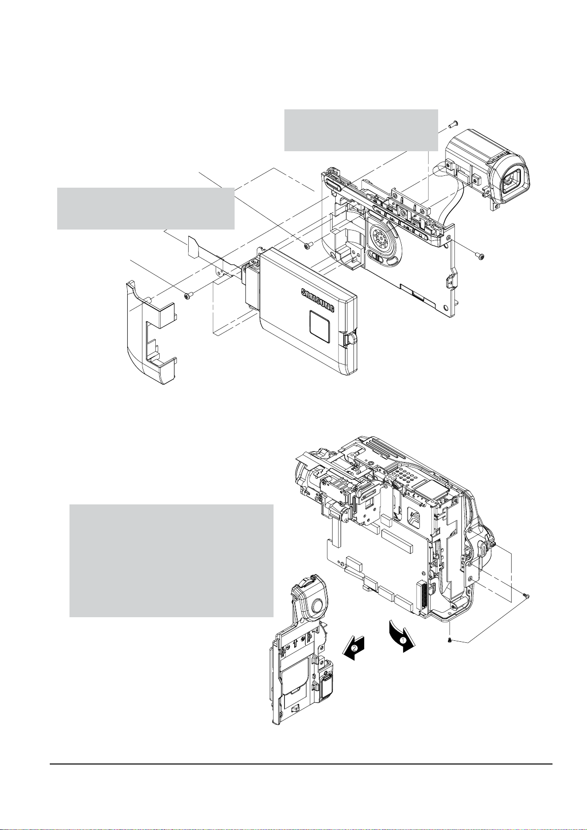
4-1-5 Ass’y LCD & EVF/CVF Removal
ΠREMOVE 3 SCREWS
(T1.7 X 4 BLK)
´ REMOVE 1 SCREW
(M1.7 X 5 WHT)
ˇ REMOVE 4 SCREWS
(T2 X 5 BLK)
¨ REMOVE 2 SCREWS
(M1.7 X 3 WHT)
Caution : Please indicate that there is a
connector on the View-Finder
that must be detached
Caution : Please indicate that this connector
must be detached before separating
the LCD Assembly
Fig. 4-5 Ass’y LCD & EVF/CVF Removal
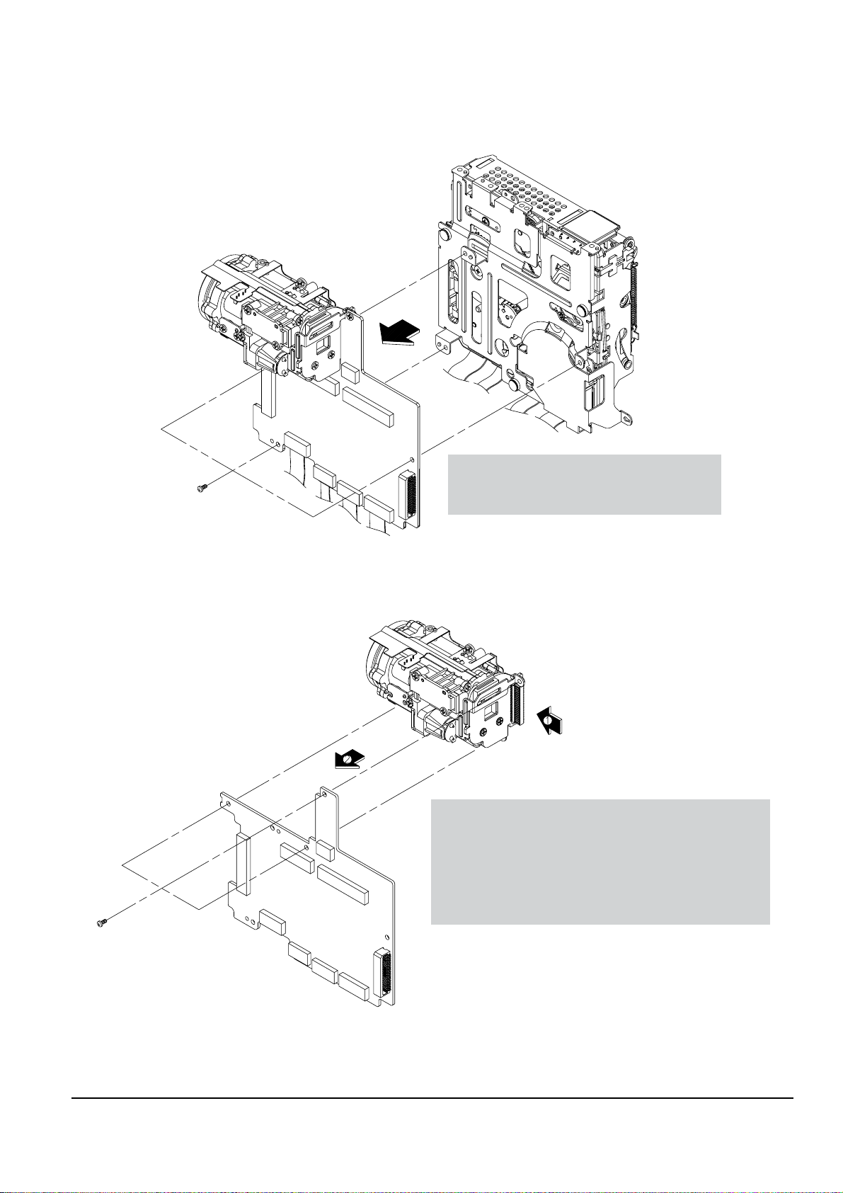
4-1-6 Ass’y Rear Removal
Fig. 4-6 Ass’y Rear Removal
ΠREMOVE 4 SCREWS
(M1.7 X 4 BLK)
Caution : The Rear Assembly is connected to the
Main PCB. Pulling it to the left as
indicated in the illustraton can cause
the connector to break. This removal
instruction should indicate that the Rear
assembly should be pulled Forward first
in order to disconnect it from the Main PCB.
Then it can be pulled to the left
to separate it from the Main PCB
Page 4
4-4
Disassembly and Reassembly
Samsung Electronics
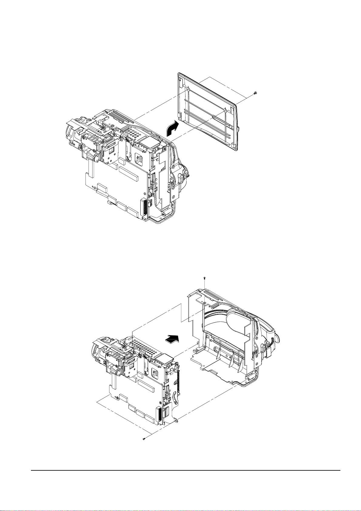
Fig. 4-8 Ass’y Right Removal
4-1-7 Ass’y Cover Housing Removal
Fig. 4-7 Ass’y Cover Housing Removal
ΠREMOVE 2 SCREWS
(M1.4 X 3 BLK)
4-1-8 Ass’y Right Removal
ΠREMOVE 2 SCREWS
(M1.7 X 4 BLK)
´ REMOVE 2 SCREWS
(T1.7 X 4 BLK)
Page 5
Disassembly and Reassembly
4-5Samsung Electronics
4-1-9 Ass’y Deck Removal
Fig. 4-9 Ass’y Deck Removal
ΠREMOVE 3 SCREWS
(M1.7 X 2.5 BLK)
Caution : Please indicate that these connectors
must be detached before separating
the Deck Assembly from the MAIN PCB.
4-1-10 Ass’y Main PCB Removal
Fig. 4-10 Ass’y Main PCB Removal
ΠREMOVE 3 SCREWS
(M1.7 X 2.5 BLK)
Caution : The Lens Assembly is connected to the Main PCB.
Pulling it to the left as indicated in the illustration
can cause the connector to break. This removal
instruction should indicate that the Lens assembly
should be pulled Forward first in order to disconnect
it from the Main PCB. Then it can be pulled to the
left to separate it from the Main PCB.
Page 6

4-6
Disassembly and Reassembly
Samsung Electronics
4-2-1 How to Load and Unload (Setting the Mechanical Modes)
1) Set the power-supply output to approximately 3V~5V, and connect it to the Motor Loading(= Loading Motor).
2) Choose the polarity depending on whether loading or unloading. (See Table 4-1)
3) Supply the voltage to the Motor Loading(= Loading Motor).
Fig. 4-11 Loading and Unloading
AB
Movement of Chassis
+
_
Unloading
_
+ Loading
<Table 4-1>
DC POWER SUPPLY
A
B
4-2 Deck
Page 7

Disassembly and Reassembly
4-7Samsung Electronics
4-2-2 Housing Ass’y
3
HOUSING LOCK L ´
ˇ HOUSING LOCK R
ΠLEVER LOCK
¨ LEVER HOUSING
ˆ SHAPE OF PIN
Ø CAM PART
∏ CAM PART
HOUSING ASS'Y ”
<DETAIL A>
"A"
Fig. 4-12 Housing Ass’y
4-2-2(a) Disassembly
1) Push the Lever(see arrow “A”, Detail A) turn the
Lever Lock Œ and open the Housing Ass’y ”.
2) Separate the Hook of Housing Lock L ´ and
Housing Lock R ˇ and then lift it.
3) Separate the Shape of Pin L and R ˆ from Cam
Parts Ø, ∏ of Main Chassis and then lift the
Housing Ass’y ”.
4-2-2(b) Reassembly
1) Mount the Shape of Pin L and R ˆ to Cam Parts Ø,
∏ of Main Chassis.
2) Mount Housing Lock L ´, R ˇ to right and left ,
and then locked.
Note : Do disassembly and reassembly in the
unloading mode.
Page 8

4-8
Disassembly and Reassembly
Samsung Electronics
4-2-3 Cover Reel Ass’y, Idler Ass’y
4-2-3(a) Disassembly
1) Lift the Cover Reel Ass’y Œ (See arrow “A”).
2) Then lift the Idler Ass’y ´.
4-2-3(b) Reassembly
1) Fit the Idler Ass’y ´ into the Pin.
2) Mount the Cover Reel Ass’y Œ to the Main Chassis
is groove in the oposite direction of arrow “A”.
"A"
2
ΠCOVER REEL ASS'Y
´ IDLER ASS'Y
Fig. 4-13 Cover Reel Ass’y, Idler Ass’y
Page 9

Disassembly and Reassembly
4-9Samsung Electronics
4-2-4 Reel Disk T, Brake T, Lever Eject
4-2-4(a) Disassembly
1) Lift up the Brake T ´.
2) Lift up the Reel Disk T Œ.
3) Separate the Lever Eject’s hook from the Main
Chassis, and then Lift up the Lever Eject ˇ.
Fig. 4-14 Reel Disk T, Brake T, Lever Eject
4-2-4(b) Reassembly
1) Insert the Lever Eject ˇ into the shape of pin ¨,
and then lock the Lever Eject’s hook Eliminate
this step.
2) Mount the Reel Disk T Œ to the pin Ø.
3) Insert the Brake T ´ into the shape of pin ˆ.
4
6
BRAKE T ´
ˇ LEVER EJECT
SHAPE OF PIN ˆ
Ø PIN
ΠREEL DISK T
¨ SHAPE OF PIN
Note 1 : When disassembling, take care not to deform
the part. Do not stain the post.
Page 10

4-10
Disassembly and Reassembly
Samsung Electronics
4-2-5 Arm Tension (=Tension Arm) Ass’y, Reel Disk S
4-2-5(a) Disassembly
1) Separate the Spring Tension (=Tension Spring)Œ
form Hook of Main Chassis.
2) Remove the Washer Slit ˇ, and then lift up the Arm
Tension (=Tension Arm) ¨.
3) Lift up the Reel Disk S ˆ.
Fig. 4-15 Arm Tension (=Tension Arm) Ass’y, Reel Disk S
4-2-5(b) Reassembly
1) Mount the Reel Disk S ˆ.
2) Push the Arm Tension (=Tension Arm) Ass’y ¨
in the direction “A”, and then insert into the Pin Ø.
3) Insert the Washer Slit ˇ, and then attach the Spring
Tension (=Tension Spring) Πto Main Chassis Hook
´ and Arm Tension Hook ∏.
4
"A"
3
SPRING TENSION (=TENSION SPRING) Œ
ARM TENSION (=TENSION ARM) HOOK ∏
PIN Ø
MAIN CHASSIS HOOK ´
¨ ARM TENSION (=TENSION ARM) ASS'Y
ˆ REEL DISK S
ˇ WASHER SLIT
Note 1 : When disassembling, take care not to deform
any part. Do not stain the post.
Note 1 : When reassembling or disassembling,
position of Spring Tension (=Tension
Spring) Πis same.
Note 2 : When inspecting the motion, Forward and
Reverse Tensions must be inspected.
Note 3 : When reassembling, confirm that the bending
of the Arm Tension (=Tension Arm) is
inserted into the Guide Cam.
Page 11

Disassembly and Reassembly
4-11Samsung Electronics
4-2-6 Drum
4-2-6(a) Disassembly
1) Remove 3 Screws Œ, and then remove the Spring
Plate ´.
2) Lift up the Drum ˇ.
7
5
4
2
1
Ø HEAD TIP
DRUM ˇ
¨ 1 BENDING
∏ PUTTING PLACE OF DRUM
ˆ 1 HOLE
´ SPRING PLATE
Π3 SCREWS
4-2-6(b) Reassembly
1) Mount and insert the Drum ˇ to the 1 Bending ¨
and 1 Hole ˆ.
2) Insert the Spring Plate ´, and then secure
3 Screws Œ.
Fig. 4-16 Drum
Note 1 : Do not touch the Head tip Ø when removing
or reassembling the Drum ˇ.
Note 2 : Do not touch the path post when removing or
reassembling
Page 12

4-12
Disassembly and Reassembly
Samsung Electronics
4-2-7 Loading Motor Ass’y, Pinch Review Ass’y
4-2-7(a) Disassembly
1) In unload mode, rotate the Pinch Review Ass’y Œ
in a clockwise direction and left up the
Pinch Review Ass’y Œ.
2) De-solder the 2 points.
3) Remove the 1 screw ˇ and separate the 1 hook of
Loading Motor Ass’y ¨.
4) Lift up the Loading Motor Ass’y ¨.
4-2-7(b) Reassembly
1) Lock the one hook of Loading Motor Ass’y ¨ and
secure one screw ˇ.
2) Re-solder the 2 wires.
(+ into red wire , - into blue wire)
3) In disassembling position, insert the Pinch Review
Ass’y Œ and rotate the Pinch Review Ass’y Œ in
unload position.
3
4
2
SOLDER POINTS
LOADING MOTOR ASS'Y ¨
ˇ 1 SCREW
ΠPINCH REVIEW ASS'Y
Fig. 4-17 Loading Motor Ass’y, Pinch Review Ass’y
Note : When disassembling and reassembling, be
careful not to touch the Pinch Roller
and the review post.
Page 13

Disassembly and Reassembly
4-13Samsung Electronics
4-2-8 Guide Roller S,T , Pole Base S,T , Gear Loading S,T Ass’y
4-2-8(a) Disassembly
1) Lift up the Pole Base S Œ(T ˇ) Ass’y form the link
of the Gear Loading S ´(T ¨) Ass’y.
2) Turn the S ˆ and T Ø Guide Rollers counter
clockwise to remove them.
3) Separate the hook of the Gear Loading S ´ and
lift down the Gear Loading S ´(T ¨) Ass’y.
6
2
3
GUIDE ROLLER S ˆ
ˇ POLE BASE T ASS'Y
POLE BASE S ASSY Œ
Ø GUIDE ROLLER T
GEAR LOADING S ASS'Y ´
∏ MAIN CHASSIS
¨ GEAR LOADING T ASS'Y
4-2-8(b) Reassembly
1) Turn the S ˆ and T Ø Guide Rollers clockwise and
reassemble.
2) Replace the S ´ and T ¨ Gear Loading assemblies.
3) Fit the Pole Base S Œ(T ˇ) Ass’y in the link of the
Gear Loading S ´(T ¨) Ass’y.
Fig. 4-18 Guide Roller S,T , Pole Base S,T , Gear Loading S,T Ass’y
Note1 : When disassembling and reassembling, be
careful not to touch the Guide
Roller S ˆ and T Ø.
Note2 : When disassemblig and reassembling the
Guide Roller S ˆ and T Ø, be careful not to
deform the Gear Loading S ´ and T ¨ Ass’y.
Note 1 : When reassembling, confirm the assemble
point.
Note 2 : Disassembly and reassembly is done in the
Unload mode.
Note 3 : After assembling, make sure that loading and
unloading work correctly by applying 3V~5V
to the Loading Motor.
Page 14
4-14
Disassembly and Reassembly
Samsung Electronics
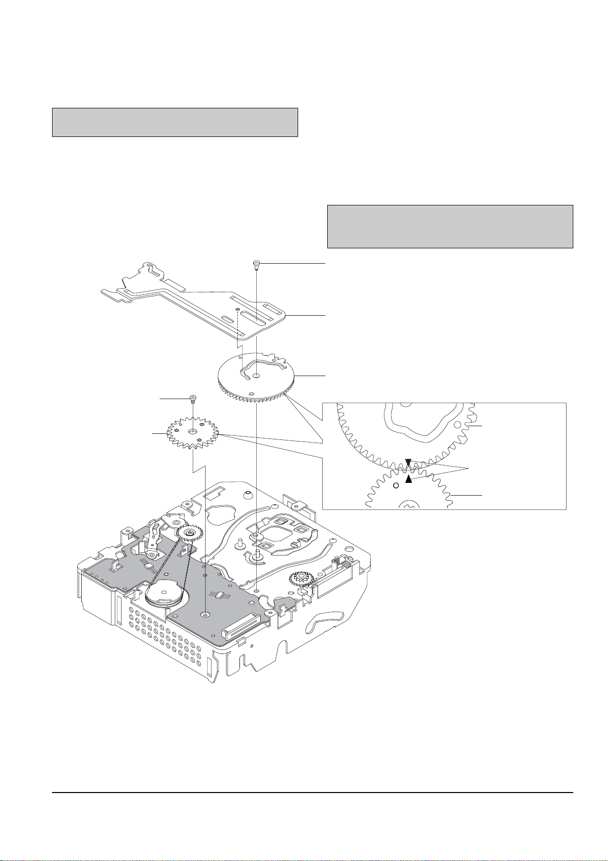
4-2-9 Slide Main, Gear Cam Main, Gear Mode Switch
4-2-9(a) Disassembly
1) Remove the 1 screw Œ and lift up the Slide Main ´.
2) Lift up the Gear Cam Main ˇ.
3) Remove the 1 screw ¨ and lift up the
Gear Mode Switch ˆ.
4-2-9(b) Reassembly
1) Mount the Gear Mode Switch ˆ and secure the
1 screw ¨.
2) After assemble and fit the Gear Cam Main ˇ,
Gear Mode Switch ˆ to assemble point.
3) Mount the Slide Main ´ and secure 1 screw Œ.
Π1 SCREW
´ SLIDE MAIN
ˇ GEAR CAM MAIN
1 SCREW ¨
GEAR MODE SWITCH ˆ
GEAR CAM MAIN
ASSEMBLE POINT
(TWO ARROWS)
GEAR MODE SWITCH
Fig. 4-19 Slide Main, Gear Cam Main, Gear Mode Switch
Note : Disassembly and reassembly must be done
with the Deck Assembly in the Unload mode.
Note : When reassembling, confirm that pin of Slide
Main ´ is inserted into the cam of
Gear Cam Main ˇ.
Page 15

Disassembly and Reassembly
4-15Samsung Electronics
4-2-10 Cover Capstan, Capstan Motor Ass’y
4-2-10(b) Reassembly
1) Mount the Capstan Motor Ass’y ¨ and secure the
2 Screws ˇ.
2) Lock the 2 hooks of Cover Capstan ´ and
1 Screw Œ.
Fig. 4-20 Cover Capstan, Capstan Motor Ass’y
2
3
4
1 SCREW Œ
´ COVER CAPSTAN
ˇ 2 SCREWS
¨ CAPSTAN MOTOR ASS'Y
4-2-10(a) Disassembly
1) Remove the 1 Screw Œ.
2) Separe 2 hooks of Cover Capstan ´ and then lift up
the Cover Capstan ´.
3) Remove the 2 Screws ˇ, and then lift up the
Capstan Motor Ass’y ¨.
Note : Be careful not to damage the gears during the
disassembly and reassembly process.
Page 16

4-16
Disassembly and Reassembly
Samsung Electronics
4-2-11 Belt Timing (Timing Belt), Gear Capstan, Gear Pulley, Lever Review
4-2-11(a) Disassembly
1) Lift up the Lever Review Œ.
2) Remove the Washer Slit ´ and lift up the
Gear Capstan ˇ.
3) Separate the Pulley Belt Timing (=Timing Belt) ¨
and lift down the Gear Pulley ˆ.
Fig. 4-21 Belt Timing (=Timing Belt), Gear Capstan, Gear Pulley, Lever Review
2
3
4
LEVER REVIEW Œ
GEAR PULLEY ˆ
´ WASHER SLIT
ˇ GEAR CAPSTAN
¨ PULLEY BELT TIMING (=TIMING BELT)
4-2-11(b) Reassembly
1) Mount the Gear Pulley ˆ and hang the Belt
Timing (=Timing Belt) ¨ on the Gear Pulley ˆ.
2) Hang the Pulley Belt Timing ¨ on the lower gear
of the Gear Capstan ˇ, and then mount the Gear
Capstan ˇ.
3) Insert the Washer Slit ´.
4) Mount the Lever Review Œ.
 Loading...