

Page 1
Samsung Electronics
3-1
3. Alignment and Adjustment
3-1 VCR Adjustment
3-1-1 Adjustment Preparation
1) Before you start
ΠUse the buttons on the CAMCORDER when adjusting VCR.
´ When changing the adjustment item, please press the “EASY-Q” and “DISPLAY” buttons on the
CAMCORDER.
ˇ The adjustment value can be changed by moving the “MENU Selector” Left or Right.
¨ Press the “MENU Selector” to store each adjustment into EEPROM.
ˆ The OSD shows “OK” after finishing each adjustment step.
Ø In order to exit the adjustment mode, disconnect the power source.
2) Function of each buttons on the Set Key
Buttons Description
MENU Selector push (Confirm) Stores changed value in the adjustment and auto adjustment mode.
MENU Selector Right (Data Down)
Changes data in the adjustment state.
MENU Selector Left (Data Up)
EASY-Q (Mode Up)
Changes mode.
DISPLAY (Mode Down)
<Table 3-1>
3) How to get into the VCR adjust mode
[STEP 1]
ΠConnect the Power source.
´ Set the Power Switch to “PLAYER” position and Mode Switch to “TAPE” position.
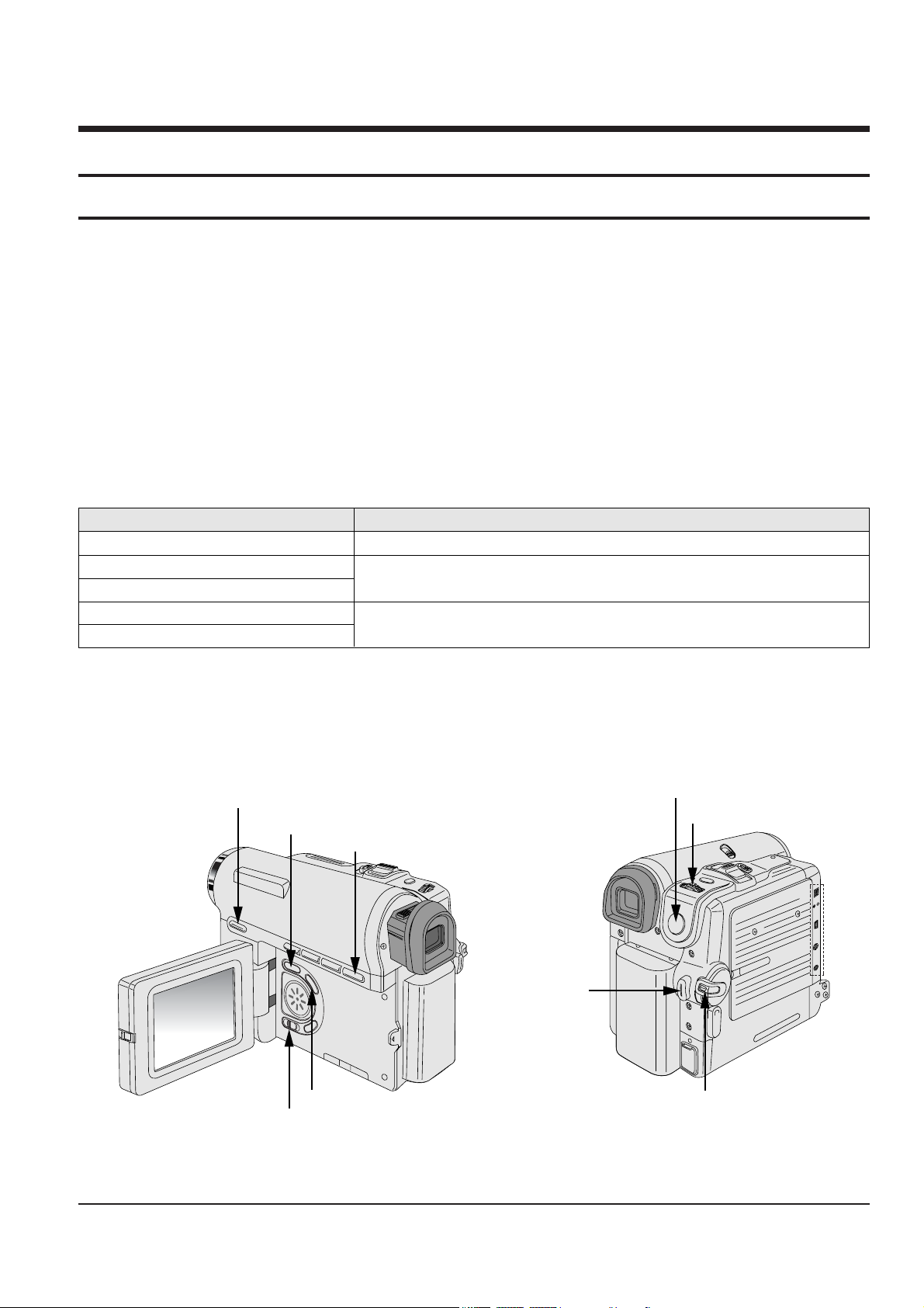
Fig. 3-1
MENU Button
EASY Q Button
Start/Stop Button
MENU Selector
DISPLAY Button
Mode switch
PB ZOOM
Power switch
STOP Button
DV
USB
AV
MIC
Page 2
3-2
Alignment and Adjustments
Samsung Electronics
[STEP 2]
ΠPress and hold the "STOP" and "PB ZOOM" buttons on the video camera at the same time for more than
5 seconds.
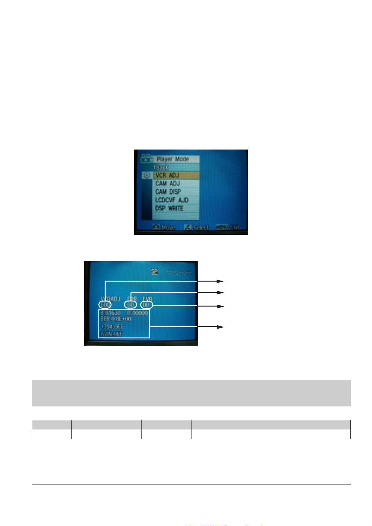
´ When monitor OSD appears as shown Fig. 3-2, the adjustment mode has been activated successfully.
ˇ Move the “MENU Selector” to highlight VCR ADJ and push the “MENU Selector”.
¨ Monitor OSD shows Fig. 3-3.
Then VCR adjustment mode has been activated successfully.
[STEP 3]
In order to complete the adjustment the power must be reset.
This can be done by disconnecting and reconnecting the power source.
Fig. 3-2
Indicates current adjustment item
Adjustment value
For Engineering Mode
Stored value
Fig. 3-3
3-1-2 VCR Adjustment
ΠGet into VCR ADJUST mode.
´ Move to the VCR ADJUST address “6IF”.
ˇ Play standard tape, and “Head Switching Position” will be adjusted automatically (within 5 Seconds).
Mode
(Address)
Name Value Description
61F SWP Position 8C Head Switching Position Adjust
<Table 3-2>
Note : This is the only electronic adjustment for the VCR.
Other addresses have already been assigned data during the manufacturing process.
We don’t need any adjustment for those addresses.
Page 3

Alignment and Adjustments
3-3
Samsung Electronics
3-2 Camera Adjustment
Note : How to adjust the camera system.
1) EEPROM stores confirmed adjustment value of each adjustment step.
2) DSP (Digital Signal Process : ICM01-Main PCB) digitalizes the camera signal.
3) When changing IC505-Main PCB of EEPROM, readjust Main PCB.
While changing LCD PCB and CVF PCB- always readjust each part.
Since EEPROM stores confirmed adjustment value of each adjustment step, readjusting must be performed in order
to store the changed data.
4) Adjust the following items after changing LENS Ass’y.
ΠLens Zoom Track
´ Auto HALL
ˇ Auto IRIS
5) Adjust the following items after changing EEPROM and Camera Main PCB.
ΠLens Zoom Track
´ Zoom VR Center
ˇ Auto HALL
¨ Auto IRIS
ˆ Auto White Balance (indoor)
Ø Auto White Balance (outdoor)
3-2-1 Adjustment Preparation
1) Before you start
ΠUse the buttons on the CAMCORDER when adjusting Camera.
´ When changing the adjustment item, please press the “EASY-Q” and “DISPLAY” buttons on the
CAMCORDER.
ˇ The adjustment value can be changed by moving the “MENU Selector” Left or Right.
¨ Press the “MENU Selector” to store each adjustment into EEPROM.
ˆ The OSD shows “OK” after finishing each adjustment step.
Ø In order to exit the adjustment mode, disconnect the power source.
2) Function of each buttons on the Sst Key
Buttons Description
MENU Selector push (Confirm) Stores changed value in the adjustment and auto adjustment mode.
MENU Selector Right (Data Down)
Changes data in the adjustment state.
MENU Selector Left (Data Up)
EASY-Q (Mode Up)
Changes mode.
DISPLAY (Mode Down)
<Table 3-3>
Page 4
3-4
Alignment and Adjustments
Samsung Electronics
5) How to set up the camera adjustment mode
[STEP 1]
ΠConnect the Power source.
´ Set the Power Switch to “CAM” position and Mode Switch to “TAPE” position.
[STEP 2]
ΠPress and hold the "STOP" and "PB ZOOM" buttons on the video camera at the same time for more than
5 seconds.
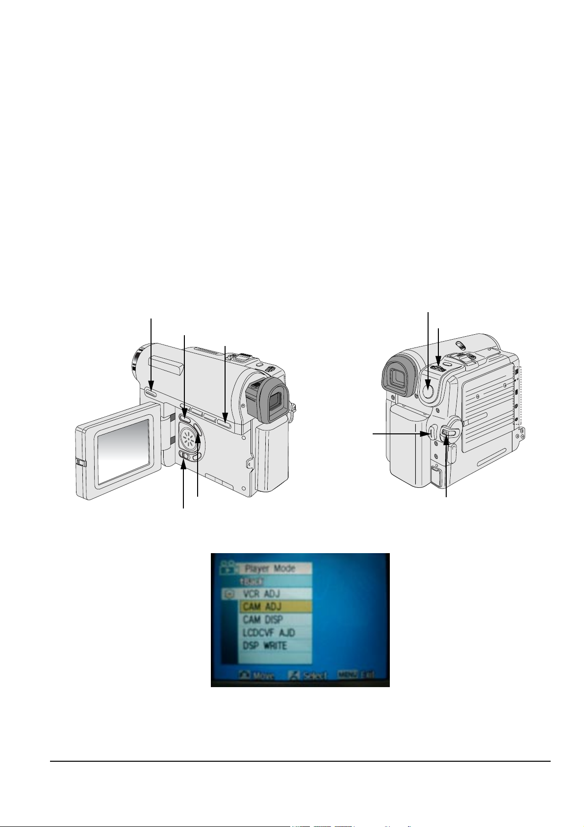
´ When monitor OSD appears as shown Fig. 3-5, the adjustment mode has been activated successfully.
ˇ Move the “MENU Selector” to highlight CAM ADJ and push the “MENU Selector”.
¨ Monitor OSD shows Fig. 3-6.
Then Camera adjustment mode has been activated successfully.
[STEP 3]
In order to complete the adjustment the power must be reset.
This can be done by disconnecting and reconnecting the power source.
Fig. 3-5
Fig. 3-4
MENU Button
EASY Q Button
Start/Stop Button
MENU Selector
DISPLAY Button
Mode switch
PB ZOOM
Power switch
STOP Button
DV
USB
AV
MIC
Page 5
Alignment and Adjustments
3-5
Samsung Electronics
3-2-2 Camera Adjustment
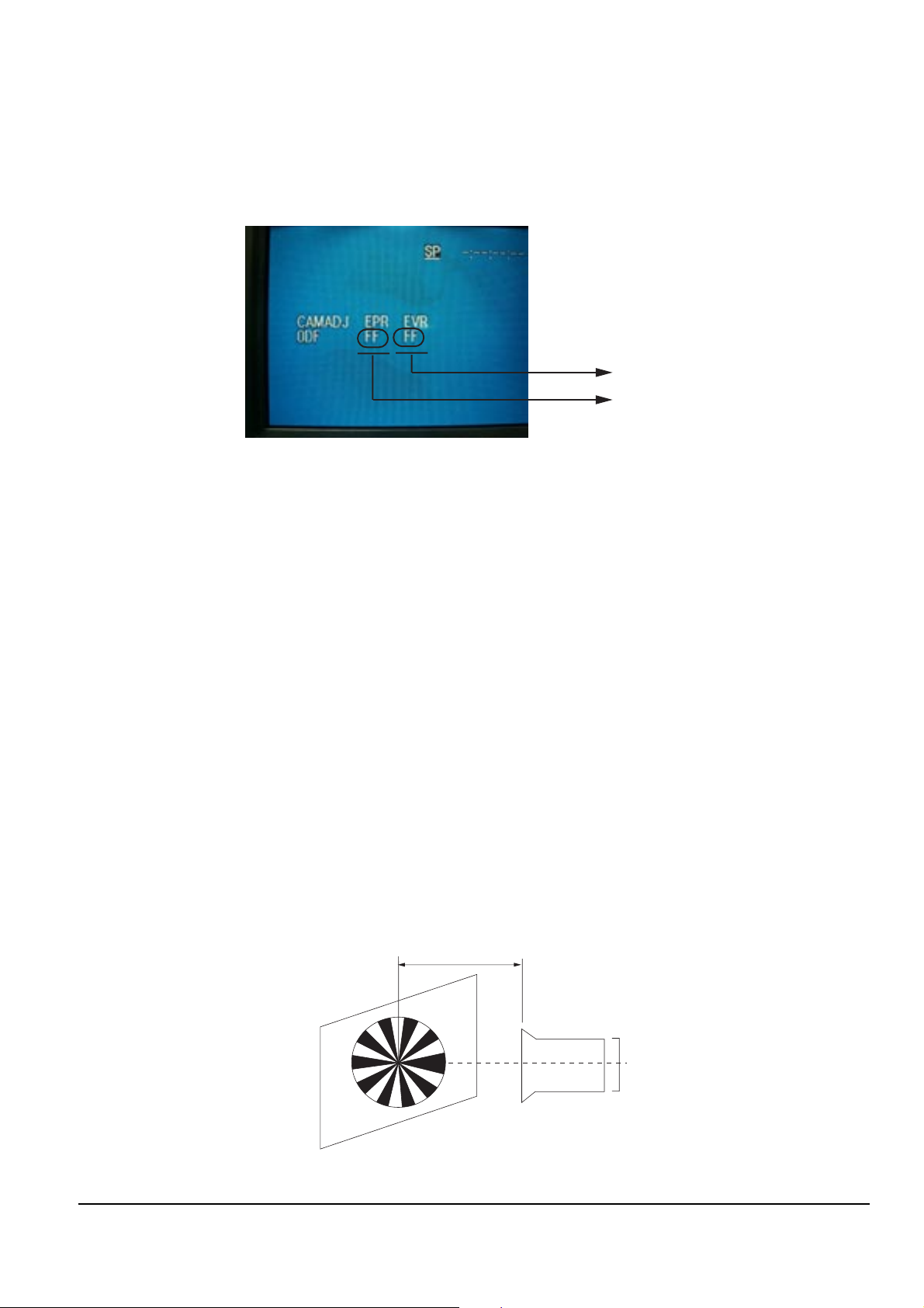
Note : "XX XX" indicate the previous preset value and adjusted value.
Press the “MENU Selector” (Confirm) to store the adjusted value.
Adjusted values
Stored values
Fig. 3-6
1) EEPROM Data Initialize
Caution : These adjustments must be done when installing a new EPROM (IC105) or Main PCB.
Œ Press the “EASY-Q”(Mode Up)/”DISPLAY”(Mode Down) buttons until CAMADJ displays “0DF XX XX”.
´ Use the “MENU Selector” (Data Up/Down) until the display data for EVR is “A0”.
ˇ Press the “MENU Selector” (Confirm).
¨ The OSD shows “OK” after finishing the initalize.
2) Lens Zoom Track
Caution : For whole zoom range, it shall be in focus.
The location of a focus lens is moving depending on the location of Zoom Lens.
During adjusting, micom measures the focus location from a near distance to a long.
ΠCamera is set to E-E mode.
´ Focus chart photo.
ˇ Center the camera about 3m from a focus chart which, should be placed on a flat surfaced white or gray wall.
¨ Connect the video output terminal to a TV.
ˆ Press the “EASY-Q” (Mode Up)/”DISPLAY” (Mode Down) buttons until CAMADJ displays “0DE XX XX”.
Ø Press the “MENU Selector” to begin adjustment.
The camera must be kept still when adjusting the zoom and focus lens.
If you don’t have any chart, you can use the object which has a lot of vertical line.
The OSD shows “OK” after finishing the adjustment.
(The word “OK” is displayed for only a fraction of a second.)
Fig. 3-7
3M ± 1cm
(Be sure to maintain the distance)
CCDLENS
Page 6

3-6
Alignment and Adjustments
Samsung Electronics
3) Zoom VR Center
ΠConnect a video output terminal to a TV.
´ Press the “EASY”(Mode Up)/”DISPLAY”(Mode Down) buttons so that OSD shows “0D6 XX XX”.
ˇ Press the “MENU Selector” (Confirm).
¨ Then Micom finds out Zoom VR center position.
Store Zoom VR center value in OB7.
4) Auto HALL
ΠConnect a video output terminal to a TV.
´ Press the “EASY-Q”(Mode Up)/”DISPLAY”(Mode Down) buttons so that OSD shows "0CD XX XX".
ˇ Press the “MENU Selector” (Confirm).
¨ Then micom finds out max. Hall value with an iris opened and min. Hall value with an iris closed.
Store max. and min. value of Hall in OAD and OAC respectively.
ˆ The OSD shows “OK” after finishing the adjustment.
(The word “OK” is displayed for only a fraction of a second.)
5) Auto IRIS Level
ΠConnect a video output terminal to a wave form monitor and a TV.
´ Press the “EASY-Q”(Mode Up)/”DISPLAY”(Mode Down) buttons so that OSD shows "0CE XX XX".
ˇ Press the “MENU Selector” (Confirm).
¨ Then micom finds out max. Hall value with an iris opened and min.
Hall value with an iris closed. Store max. and min. value of in 00BC, 00BD and 00BB respectively.
ˆ The OSD shows “OK” after finishing the adjustment.
(The word “OK” is displayed for only a fraction of a second.)
6) Auto White Balance (indoor)
Œ Camera mode & 3100˚ K gray scale chart.
´ Connect a video output terminal to a vectorscope and a TV.
ˇ Press the “EASY-Q”(Mode Up)/”DISPLAY”(Mode Down) buttons so that OSD shows "0D4 XX XX".
¨ Ensure that camera picks up image 40µs on 3100˚K gray scale chart precisely and the illumination is 1500~2000
Lux.
ˆ Press the “MENU Selector” (Confirm) to ensure that white spot on a vectorscope is moving in the middle of
screen.
Ø The OSD shows “OK” after finishing the adjustment.
(The word “OK” is displayed for only a fraction of a second.)
7) Auto White Balance (outdoor)
Œ Camera mode & 5100˚ K gray scale chart.
´ Connect a video output terminal to a vectorscope and a TV.
ˇ Press the “EASY-Q”(Mode Up)/”DISPLAY”(Mode Down) buttons so that OSD shows "0D5 XX XX".
¨ Ensure that camera picks up image 40 µs on 5100 gray scale chart (3100 gray scale chart + C16 filter) precisely
and the illumination is 1500~2000 Lux.
ˆ Press the “MENU Selector” (Confirm) to ensure that white spot on a vectorscope is moving in the middle of
screen.
Ø The OSD shows “OK” after finishing the adjustment.
(The word “OK” is displayed for only a fraction of a second.)
Page 7

Alignment and Adjustments
3-7
Samsung Electronics
3-3 Deck Adjustment
3-3-1 Operation Without Housing Assembly
1) Remove the Housing Ass’y from the Deck Ass’y.
2) Connect the Mechanical Chassis to the recorder
circuit to supply voltage.
3) Set to Unload mode.
4) Press the S/W Push (Keep ON status)to start loading, and push the PLAY Key.
(Cover the Top/End sensor with black tape,
because they do not operate.)
Note : For the removal of the Housing Ass’y refer to
4-2-2 (page 4-7).
Connceted the Recorder Circuit
SWITCH C-IN
Fig. 3-8
3-3-2 Setting Mechanical Mode (Without Recorder Circuit)
1) Set the power-supply output to approx. 3V~5V.
2) Choose the polarity (depending on whether loading or unloading).
3) Supply the voltage to the Motor Loading, and set
to the desired mode.
Fig. 3-9
DC POWER SUPPLY
A
B
<Table 3-4>
AB Movement of Chassis
+- Unloading
-+ Loading
Page 8

3-8
Alignment and Adjustments
Samsung Electronics
3-3-3 Maintenance
Carry out the following periodic maintenance checks in order to fully exercise all functions, operations and tape.
After repairing, service the set as follows:
1) Cleaning of Drum Assembly
ΠGently apply lens tissue soaked in ethyl alcohol to the Drum assembly.
Clean the Upper Drum assembly while rotating it slowly counterclockwise(by hand).
Note : Do not rotate the motor by power or rotate the Upper Drum assembly clockwise.
Also, the Head tip will be damaged if the lens tissue is moved in a perpendicular direction.
Be sure to follow these instructions when cleaning the Drum Ass’y
2) Cleaning of Tape Path
ΠIn EJECT mode, clean the tape path system(from Pole Tension P1 through Pole Review P9, Pinch Roller and
Capstan Shaft) and the Lower Drum. Using the lens tissue soaked in ethyl alcohol.
Note : Make sure that no oil or grease adheres to the lens tissue.
Fig. 3-10
P5
P2
P4
P3
P1
P8
P6
P7
P9
PINCH ROLLER
Page 9

Alignment and Adjustments
3-9
Samsung Electronics
3) Periodic Maintenance and Check List
When overhauling, refer to the following table.
2mm
OIL
◆ When lubrication bearings, be sure to keep the oil
free of dust. (Oil contaminated with dust might
cause the bearings to wear out or seize.)
◆ A “drop”of oil is defined as the amount attached to
the tip of a Ø 2mm stick as shown in Fig. 3-11.
<Table 3-5>
Fig. 3-11
O : Cleaning ∆ : Oil ◆ : Confirmation
Tape
path
system
D
R
I
V
I
N
G
S
Y
S
T
E
M
- Never let oil get on to the tape path
surface.
Maintenance checks
Hours of use (H)
Remark
500 1000 1500 2000 2500 3000 3500 4000 4500 5000
Cleaning of tape path O O O O O O O O O O
Cleaning and degaussing of drum ass’y
OOOOOOOOOO
Capstan Shaft ∆∆∆∆∆
Gear Capstan ∆∆∆∆∆
Gear Pully Shaft ∆∆∆∆∆
Belt Timing ◆◆◆◆◆
Motor Loading ◆◆◆◆◆
Abnormal Noise ◆◆◆◆◆◆◆◆◆
Back Tension ◆◆◆◆◆
Brake System ◆◆◆◆◆
PB, REV Torque Measurement
◆◆◆◆◆
Confirmation
Perform-
ance
Page 10

3-10
Alignment and Adjustments
Samsung Electronics
3-3-4 Mechanical Check and Adjustment
3-3-4(a) Tension Regulator Adjustment
1) Disassembly
Œ For the removal of the Housing Ass’y refer to 4-2-2 (page 4-7).
2) Adjustment
ΠSet to PLAY mode (without cassette tape).
´ Check that the distance between external surface of Holder Loading and extenal diamater of Arm Tension is
1±0.5mm. (Fig. 3-12)
ˇ If necessary, proceed to step 4.
¨ If the Arm Tension Œ is located inside (or right) the position specified, adjust the Cap Adjust Œ toward
arrow “A”. (If it is located outside (or left), adjust toward arrow “B”.)
Note : Check if the Arm Tension can be moved toward arrow “C” in PB mode.
3) Reassembly
Œ For the removal of the Housing Ass’y refer to 4-2-2 (page 4-7).
Fig. 3-12
1 0.5
ARM TENSION Œ
CAP ADJUST ´
"B"
"A"
Page 11

Alignment and Adjustments
3-11
Samsung Electronics
3-3-4(b) Back Tension Confirmation
1) Set up the cassette-torque tape.
2) Set to CAMERA mode, push the EDIT(+) KEY and check that the torque value of Reel S is 4±1g.cm.
3) If necessary, proceed to step 4.
4) If the Tension value is Low specified, moved to toward “a”.
If the Tension value is High specified, moved to toward “b”.
Reference : After changed, insert Cassette torque tape and confirm torque value.
Fig. 3-14
REEL DISK S TABLE
RESTING SURFACE
REEL DISK T TABLE
RESTING SURFACE
CHASSIS MAIN
Fig. 3-13
b
a
3-3-4(c) PB/REV Torque check
1) Set up the cassette torque tape.
2) Set to CAMERA mode, Push the EDIT(+) button and check that the torque value of Reel T is 9.5±3.5g.cm.
3) Push the EDIT(-) button and check that the torque value of Reel S is 15±4g.cm.
4) If necessary, replace the defective Reel Disk S, T Ass’y.
3-3-4(d) Reel Table Height Check
1) Removal
Œ For the removal of the Housing Ass’y refer to 4-2-2 (page 4-7).
´ For the removal of the Idler Ass’y refer to 4-2-3 (page 4-8).
2) Check
ΠUsing vernier calipers, check the following distances : From the upper surface of the Main Chassis to the
resting surfaces of Reel S, T table should each be 3.9±0.15mm.
3) Mounting
Œ For the removal of the Idler Ass’y refer to 4-2-3 (page 4-8).
´ For the removal of the Housing Ass’y refer to 4-2-2 (page 4-7).
Page 12

3-12
Alignment and Adjustments
Samsung Electronics
3-3-5 Tape Path Adjustment
3-3-5(a) Preparation for Adjustment
ΠClean the tape running surface (Poles, Drum, Capstan Shaft, Pinch Roller).
´ Observe the PB RF signal and Head Switching Pulse on an oscilloscope.
ˇ Play back the alignment tape.
¨ Check that the waveform of the RF signal is flat at both inlet and outlet(A in Fig. 3-15).
If not flat (B or C in Fig. 3-15), do adjustments 3-3-5(b) through 3-3-5(d).
P1
P2
P3
P4
P5
P7
P6
P8
P9
Fig. 3-16
A
B
C
INLET OUTLET
NORMAL
DEFECT AT INLET
DEFECT AT OUTLET
Fig. 3-15
Page 13

Alignment and Adjustments
3-13
Samsung Electronics
3-3-5(b) Tracking adjustment
ΠPlay Back the alignment tape.
´ Turn P3 to flatten the waveform at the inlet.
ˇ Turn P7 to flatten the waveform at the outlet.
3-3-5(c) Take Up Path Adjustment
ΠPlay back the alignment tape, and confirm that the tape is not twisted between the Guide Roller T and
Capstan. (Fig. 3-17)
´ Set to REV mode and observe the outlet waveform of PB RF signal. (Fig. 3-18)
NOTE : If the outlet waveform is out-of-spec, replace the Arm Review or the Arm Pinch Ass’y,
and redo steps 1 and 2.
P9
P8
P7
P6
P4
P3
MOTOR CAPSTAN
Fig. 3-17
(DEFECTIVE) (CORRECT)
Fig. 3-18
Page 14

3-14
Alignment and Adjustments
Samsung Electronics
3-3-5(d) Check After Adjustment
1) Tracking Check
ΠPlayback the alignment tape.
´ Confirm that the minimum amplitude value(E min.)is 80% of the maximum value(E max.) or larger.
(Fig. 3-19)
ˇ Confirm that no large fluctuation occur on the waveform. (Fig. 3-20)
2) CUE and REV Check
ΠPlayback the alignment tape, and set to REV mode.
Confirm that the waveform peaks have a uniform Pitch. (Fig. 3-21 A)
If the track pitch is not uniform, do section 3-3-5(b) (Tracking adjustment).
´ Set to CUE mode.
Confirm that the waveform peaks still have a uniform pitch. (Fig. 3-21 B)
If the track pitch is not uniform, do section 3-3-5(b) (Tracking Adjustment).
Emin Emax
Emax
Emin
80(%)
Fig. 3-19
A
A
C
C
C
1
8
Fig. 3-20
abc a
abc
bc
Fig. 3-21
Page 15

Alignment and Adjustments
3-15
Samsung Electronics
3) Rise Time Check
ΠPlayback the alignment tape.
´ Set to playback mode, and confirm that the waveform of PB RF signal rises flat within 3 seconds.
Also confirm that the tape is not twisted or curled around the Pinch Roller. (Fig. 3-23)
ˇ Run the tape in CUE/REV and FF/REW modes, then playback.
Confirm the waveform of PB RF signal rises flat within 3 seconds. Also confirm that the tape is not twisted or
curled around the Pinch Roller.
¨ Repeat steps 2. and 3.
4) Tape Path Check
ΠIn CUE and REV modes, check that the tape is not curled around the P3, P7 upper flange and P9
upper/Lower flanges.
P9
P8
P7
P6
P4
P3
MOTOR CAPSTAN
Fig. 3-22
P1 P2 P3 P4 P6 P7 P9
FROM THE S REEL
TO THE T REEL
Fig. 3-23
Page 16

3-16
Alignment and Adjustments
Samsung Electronics
MEMO
 Loading...