

Samsung 7050 series, 7000 series, UN40D7000, UN46D7000, UN55D7000 User Manual
...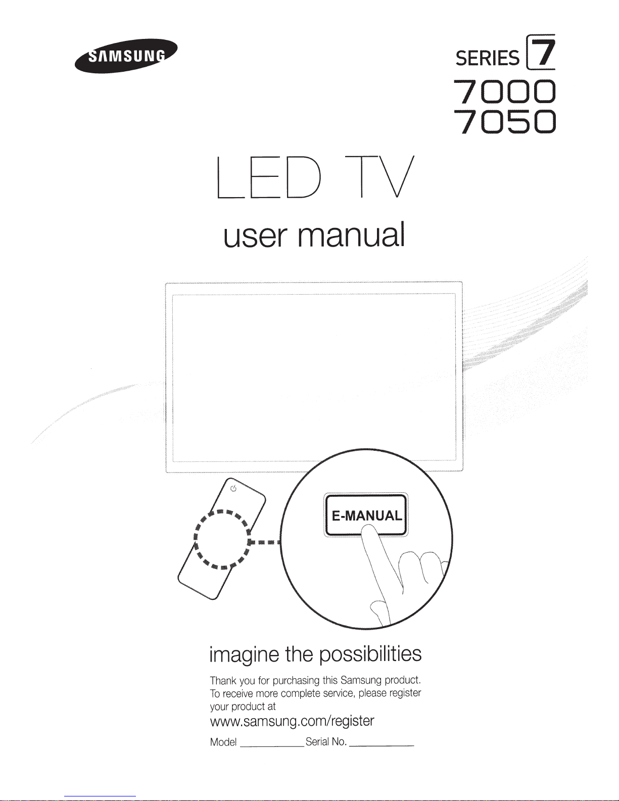
LED TV
user manual
SERIES[]
7000
7050
#
;
0
1
0
....
.f
#
imagine
pu
for
you
ank
Th
more
ve
ei
rec
To
sam
at
sung
product
your
www.
l
ode
M
the
chas
r
comp
possibilities
this
g
in
service,
lete
.com/register
No.
l
Seria
Samsung
as
ple
__
_
product.
ster
regi
e
_
Figures
Product
and
illustrations
design
and
specifications
in
this
User
Manual
may
be
changed
are
provided
without notice.
for
reference
only
and
may
differ
from
actua
l
product appearance.
Important
~
See
the
warranty card for more information
Wide
screen
format
to
view
wide
screen
ratio
format, or
stationary graphics
programming,
Additio
nally,
site
s or computer
for more
in
ghost
images,
different
Be
c
areful
se
lection
•
SAMSUNG
Subject
Electronics
SAMSUNG
in
Canada
spe
The
State
the
are
product.
Excluded.
repair
For
-
In
-
In
expanded
should
viewing
than
5%
images
in
not stationary patterns or dark
formats
c
a
Se
limited
th
the
Canada:
about the
a
nd
use,
to
the
,
and
ified,
and
bove
de
ment,
rv
ice
only
but
times,
e
loca
Unite
as
E
(SAMSUNG)
will
the
Ce
e
tion
Warranty
LED
Displays
format
to
and
images
be
limited
other stationary
graphi
cs
of
total
viewing time
the
LED
a
full
screen
television
as
well
as
LECTRONI
requirements,
additionally
in
Canada
to
the
O
sc
ribed wa
Original
nter.
Tran
to manufacturing defects
not
limited
xc
hanges
of a
S
AM
d
St
at
es
: 1-800-
1-800-SAMSUNG
(w
full-motion
fill
the
screen
on
screen,
to
no
and
patte
picture.
picture.
formats
burned
CS
NORTH
conditions,
products,
provide
on
SAMSUNG
rigin
al
Purchas
rr
a
nty
r
Limited
sportati
to, are
or
replace
S
UNG
SAMSUN
i
th
more
images
rns,
To
in
epair
Warr
on
any
Authori
Information Regarding
on
warranty terms.
16:9 aspect
video.
if
your
such
than
should
can
cause
avoid
bars.
you
select
images,
AMERICAN
and
the
Warranty
er
only
s
mu
a
nty
to
and
originally
ment
s,
z
G
ratios,
the
The
images
displayed
model
offers
as
the
dark sidebars
5% of
the
and
text
such
as
be
limi
ted
as
uneven
aging
this,
vary
the
programming
On
LED
models
and
the
length
are not c
exclusions
requirements
products
.
st
be
St
atement
from
in
material
accessories, optio
ed
Servi
(1
-800-
overed
LIMITED
and
Repair
Service
pu
pe
rf
or
med
an
the
Se
rv
or workmanship,
specified
ce
Center,
726
-7
rchased
d a dated
ratio
of the
on
this
feature
total television
stock market
desc
rib
of your
that offer picture si
of time
by
your
WARRANTY
limitations
, conditi
ice
provisions for, in-home
864)
in
the United
in
by a
SAMS
Center
ns,
pl
ea
ons,
upgrad
se
them
with t
on
non-ex
ed
ab
LED
and
you
Samsung
of the
exc
the
U
UNG
Bill
of
is
the
and
ca
ll
screen
vi
ni
to
Television
width to
should
primarily
he
images
panded
ewi
ng
per
week
crawls,
video
o
ve
f
or
all
televi
displ
ay
and
images,
view
STATEMENT
l
t
Sal
re
es
and
zing
features,
them.
limited
o
ri
ginal
Limited
us
i
ons
and
States
on
ed
States,
Auth
o
ri
e
as
Proof
sp
onsibility
only
those encounter
or
on-site
, or
c
onsum
ll
-fr
ee:
z
Format Viewing
height)
are
primarily
be
in
the
wide
constan
standard form
game
leave
primaril
LED
wa
limitations
SAMSUNG
for
ed
of
of the
a
.
s
ion
t
he
Se
Purc
bles
tly
in
motion.
at
disp
lay
s,
s.
Di
sp
l
aying
subtle
,
but
y di
splay
use
these
ag
i
ng
as a
re
rr
anty.
War
ranty
supplied
co
ntained
products purchased
warran
ty
rvi
ce
Ce
nt
e
has
e
must
purc
h
aser.
ed
in
servic
es
,
minimum
.
television
controls
period
r.
normal
designed
screen
Displa
station
logos,
st
ationa
permanent
full
screen
to
s
ult
of fo
rmat
with
herein,
or
i
gin
Al
o
ng
with
be
pre
se
Co
ndi
t
ion
use
or
16
:9
ying
video
web
ry
imag
burnedmo
v
vie
w
Samsung
ally
th
is
nted to
s co
of the
max
im
an
ing
vere
um
d
es
d
Av
o
id
di
s
pl
a
ying
sti
ll
im
ag
at the scre
c
an
recommendations below:
•
•
•
•
c
aus
Avoid
Alw
ays
Re
du
Use
e
a
en
imag
di
ce
ll
s
try to
brightne
TV
bottom etc
e burn-in
pl
a
ying
the
di
s
pl
ss
fe
atur
es
ay
and
desig
es
(such
.)
, or progr
on
the
same
a
ny
ima
contr
ned
TV
as
LED
cha
ge
as
to r
jpeg picture
am
s
in
panora
s
cr
ee
n,
nnel
for
in
full
scr
t to avo
id
edu
ce
which
long
ee
the
im
ag
Still
image warning
file
s),
sti
ll
im
ma
or 4
:3
im
will
a
ffect
peri
od
s.
n.
U
se
the
TV
app
earanc
e of after-im
e
retention
a
nd
age
age fo
imag
set's
sc
elements
rm
at on
e
quality.
pi
cture for
ages
reen
burn. R
(suc
th
To
ma
.
h
e s
re
du
t me
efer
as
TV
cre
e
ce
nu
to thee-
cha
n.
Cons
risk
of
for the b
nn
el l
tantl
thi
Manu
ogos,
stock or news bars
y di
spl
a
ying
s e
ff
ect,
pl
eas
est
poss
ibl
al
for
deta
s
till
pictur
es
e fo
ll
ow
t
he
e
mat
ch.
il
s.

Please make sure the
~
~The
~
item's colors and shapes may vary depending on the model.
that there are no accessories hidden behind or under packing
ck
Che
foll
ow
items are
ing
Accessories
cluded with your
in
any items are missing, contact your dealer.
If
TV.
terials when you open the box.
ma
Cables
Input
To purchase the
...
...
(Sold
1-
Separately)
232
RS
..
cable, con
tact
.SamsungParts.com .
www
~
~
~
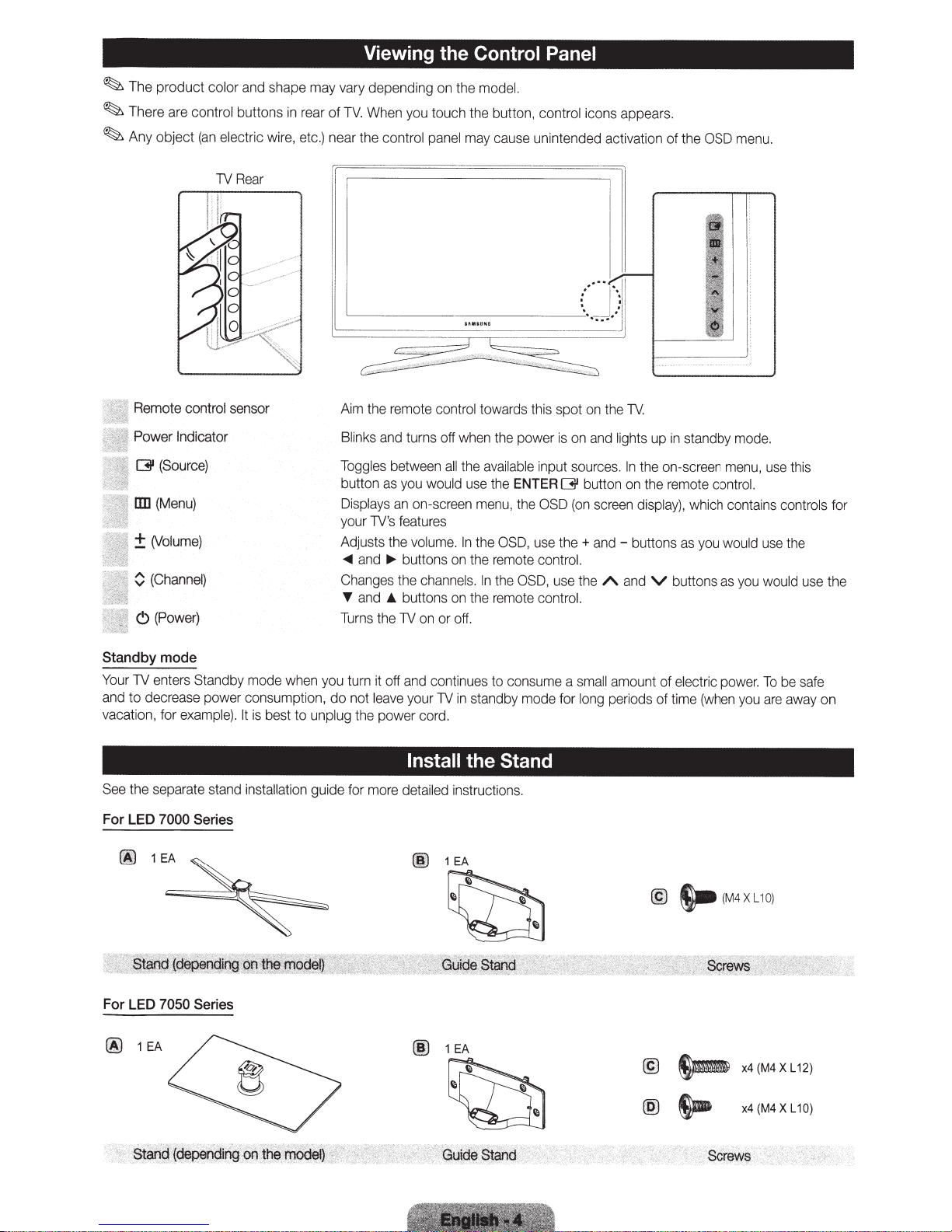
The
product color
There
are
Any
object
and
shape
control buttons
(an
electric
TV
wire,
Rear
in
may
rear
etc.}
Viewing the Control Panel
vary
of
TV.
near
depending
When
the cont
on
the
model.
you
touch the button, control icons appears.
ro
l
panel
may
cause unintended activation
of
the
OSD
menu.
Remote control sensor
Power Indicator
(31
(Source}
liD
(Menu}
±(Volume}
0
{Channel)
C)
(Power}
Standby
Your
and
vacation, for
See
mode
TV
enters Standby mode
to decrease power consumption, do not
example}.
the separate
stand
when
It
is
best to unplug the power
in
sta
ll
at
ion
you
guid
Aim
th
e remote control towards this spot
Blink
s
and
turns
off
when
Toggles
button
Displays
your
Ad
~
Changes
T
Turns
e for
justs
and
and
turn
as
TV
's featur
the
~
._
the
it
off
leave
more
between
you
would
an
on-screen
es
volume.
buttons
the
channels.
buttons
TV
on
or
and
continues to cons
your
TV
cord.
Install
detailed
all
the
available
use
menu
In
the
on
the
In
on
the
off.
in
standby
the Stand
in
structions.
th
e power
the
ENTER
, the
OSD,
rem
ote
the
OSD,
remote
mode
is
input
[31
OSD
u
se
the+
contr
use
control.
ume
for
on
on
and
sources.
button
(on
screen
and-
ol.
the
a
sma
long
the
TV
lights up
In
on
A
and
ll
amount
pe
riods
1------=
.
the
on-screen
the
remote
display},
buttons
V
of
of
in
standby
which
as
you
buttons
electr
time
(when
I ·
1.\
'""=-
·_j
j
mode.
menu
,
control.
contains cont
would
u
as
you
would
ic
power.
To
you
use
se
are
t
t
he
be
away
his
use
sa
ro
fe
ls for
the
on
For LED 7000
00
For LED 7050
(j)
1
'. '
.•
·s·
·
t;:.;;..
'
•
on
'
1
EA
..
,
i
.....
EA
~
·
>
·.·
-
(i'ion
Series
Series
.·
· •
;;;.:..
_·
:a.
...
_,I;J
~?1-'
...
·
.·n
'
'"
o'.
·.
t
·
h
.
~
·
·
e
"~
~d
·
·
·
;.,_
··
·
g
n -
.
..
.
...
. ,
,.,
..
"'"'
,.
'·'·'
""\
..
•.
.!
.
·~
·.
:.·
•.
·.·.
_
..
: .•
,.·
..
•
..
·.•
•.
..
·
··
.......
,
.""''
~
,•
.
..
· ·
•
..
·_,,q;.,~~'
,:~·
'
•
00
1
EA
~
@
1
EA
~
..
,,.
'··
· ··
..
..
>·)
"'
_ ·
.·
~
y
uid.e
r.
.··
st
..
anq
·
..
·_
(jj
@
@
s-
~
~
(M4XL10)
x4(M4XL12)
x4(M4XL10)
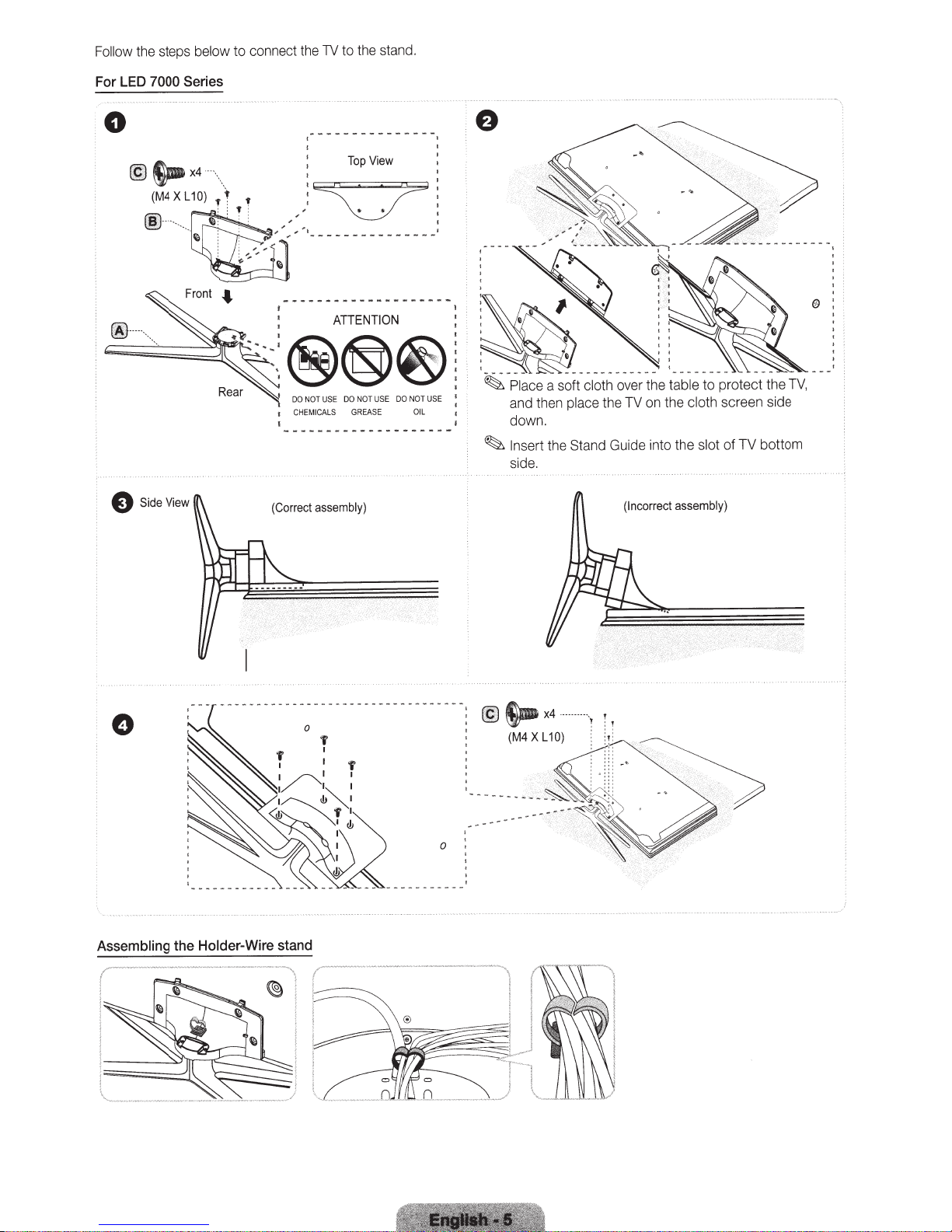
Follow
LED
For
0
the steps
7000
S.x4
@
(M4XL10)
..
~
-·
to
below
connect the
to
TV
Series
··\. , ,
Top
~;
:
; • • :
,'
- - - - - - - - - - - -
-
1 ...
'"
,
""
,
II)
......
~r
•• •
...
r"
:
l
ATIENTION
DO
USE
OT
N
DO
CHEM
ICALS
G
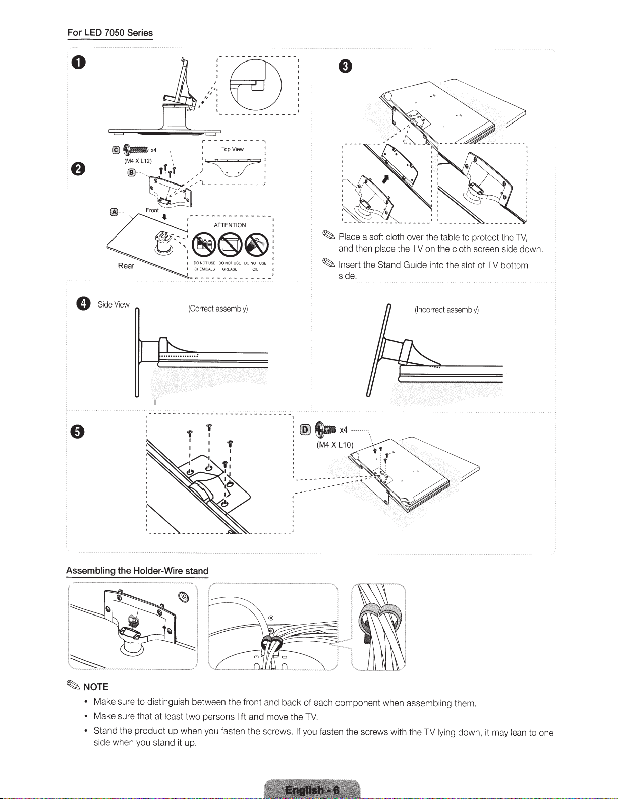
the stand.
View
DO
USE
NOT
SE
REA
NOT
OIL
....
USE
a soft
Pl~ce
-
~
and then
down.
the Stand Guide into the
Insert
~
side.
cloth over the
the TV on the
place
table
cloth
protect the TV,
to
screen side
TV
of
slot
bottom
SideView
e
Assembling
Holder-Wire
the
(Correct
stand
assembly)
r··--
i
'
-·-
-··-·-
·
···
·-·-----···
-·---·1
··
I
i
~
(Incorrect
assembly)
0
0
@~x4
SideView
(M4XL12)
® ' .
~;::
~
Front
r---------;
·
·,
\
' , I 1
,,
I
(Correct
1'
I
11
~
)
'l
- - - - - - - - -
00
NOT
US
E
DO
CHE
MICA
LS
assembly)
'
TopView
• '
N
OT
USE
GREASE
DO
NO
O
'
~
T
USE
il
I
I
~
Place
a soft
cloth
over the
and then place
1
~
In
sert
the
the TV on the cloth screen side
Stand Guide
in
to the slot
(Incorrec
table
to protect
t
assembly)
th
of
TV bottom
e TV,
dow
n.
~s-x4
(M4
XL
10)
~-
Assembling
. !
t
~
~
NOTE
•
•
• Stand
the
Holder-Wire
_.
___
_
____
Make sure to distinguish between the front and back of each
Make sure that at
the product
side when you stand it
---
-
stand
~--
....
..
....
I
_..-,;:o---,
~
\
~
i
I
_)
l
east
tw
o persons lift
up
when
yo
u fasten
up
.
"-·----
'l==
~~
and move the
th
e screws .
---
-
--·
---·--···-
··
···- , I
1
1
==;;o=-::::
=::::::::~
~~~~~
TV.
If
you fasten the screws with the TV lying
1
I
~
J
___
J
comp
onent when assembling them.
dow
n,
it may lean to one

Installing the
Wall
Mount
Preparing
install
To
Installing
The
For
contact a
damage
Wall
~
before
wall-mount
a
Wall
the
mount
wall
detailed
information
technician
to the product or
Kit
Mount
your
Install
kit
wall
plaster board,
fall
may
it
wall,
~NOTE
Standard dimensions for
•
Samsung
•
use
not
Do
•
use
not
Do
•
specifications.
mounts that do
l
wal
For
•
depending
fasten
Do not
•
Samsung
injury.
Samsung
•
the consumer
not mount
Do
•
have
ays
Alw
•
installing
Mount
(sold
Specifications
mount
please
and
wall
Wall-Mount
another
from
Kit
separately)
insta
on
assistance
for
injury
on
contact your
result
mount kits
manufacturer,
allows
t
lling
hen
w
yourself
to
(VESA)
a solid
ve
se
in
l
wal
ntain
co
you
mount,
wall
he
installing
or others if
perpendicular
wall
nearest
personal
re
mount kits
a detailed
to mount
dealer for additional
are
screws that do not comply with the
the
than
longer
screws that
Screws
the
on
the
not
is
fails
the
two people mount
are
are
that
t comply
no
mount specifications.
wall
firmly.
s too
rew
sc
for
liable
not
is
product damage or personal injury
for
liable
the product
follow
to
more
at
TV
too
these
than
the
may
long
the
with
may
s
hi
T
kinds of accidents.
installation
degree
15
a
on
TV
Holder-Ring.
the
use
on
1V
the
instructions
the
see
bracket.
mount
ll
wa
the
elect to
you
floor.
the
to
injury.
the table below.
in
shown
stallation
in
VESA
standard
manual
standard screw specifications.
length
cause damage to the
standard screw specifications, the
ESA
V
product or
damage
the
instructions.
t.
til
wall.
a
wall.
the
with
ided
prov
ung
ms
Sa
mount
all
the w
install
attaching the
Before
you
If
n.
io
t
rma
info
nec
rts
pa
all
d
an
do not comply with the
or
the
of
ide
ins
th
use
ca
non-VESA
a
when
un
mo
wall
the
not
your
wall
is
own.
nt to surfaces other
mou
TV
the
Electronics
on
install
essary for assembly
VESA
set.
TV
gth of the sc
len
e product to
or non-sp
fal
eci
for
you
any
recommend
We
t.
responsible
on a ceiling or slanted
provided.
are
standard screw
may
s
rew
leading to personal
l,
used
is
mount
wall
fied
than
differ
or
19- 22
23- 27 200
1\1
-
LED
32-40 200
46-55
56-65
your
tall
s
in
Do not
shock.
c
ri
elect
75 X 75
X
X
X
400
600 X
Wa
100
200
400
400
Mount Kit
ll
wh
il
e
M4
M8
your
1V
turned
is
4
on.
may r
It
es
ult
personal
in
injury
du
e to

Remote Side View
Displays
and
selects
Turns
Gives
direct
access
Press
to
select
broadca
, to
additional
st
by
the
select channel
'54',
then
Adjusts
being
example
the
available video
the
TV
on
to channels.
digital
same
station. For
'54-
press'-'
the vol
sources.
and
off.
channels
3', pr
ess
and '3'.
ume
QWERTY Remote (RMC-QTD1)
.
Turns the
off. When
illu
minated
(Using the
set to
On
ti
me.)
Ret
urns to
MUTE:
Cuts
CH
LIST: Displays
screen.
Changes
remote
control light
on,
the
buttons
for a moment when pre
remote
will
redu
the
previous
otf
channels.
become
cont
rol with this
ce
the battery
channel.
the
sound temporarily.
chan
nel
lis
ts
on
on the
or
ssed.
button
usag
e
Link
Quic
kly select fre
Selects
changes
U
se
to
var
ious application
quently use
the
on-scr
een
values
s to
sed
SMART
in a spec
menu
seen
the
previous men
1n
the
HUB menu, etc
the
Return
Buttons u
these
buttons
For details, refer to e-Manua
services.
d f
unctions.
items
on
the
menu.
Channel
1fic feature.
Opens the
Support
word and
Displ
and
~~~---;-.....;.~
u.
and
--:+---11
.
l.
RETURN
~I
(A
II
B
II
c
EXIT
II
0)
-::-------:;..-
Exi
SOCIAL
applicati
YAHOO!/
wi
~J:
E-MANUAL: Displays the
P.SIZE
CC: Displays
OSD.
to
recommendation
search function.
ays
information
ts
the
menu.
TV:
Connect
on.
HOTAPPS:
dget.
Turns the 3D image on
: Le
ts
you select the
dig
ital
sub
search
on the
TV
to
Social
Runs Yahoo
or
e-Manual.
Picture
titl
es.
scree
TV
off.
n.
Size.
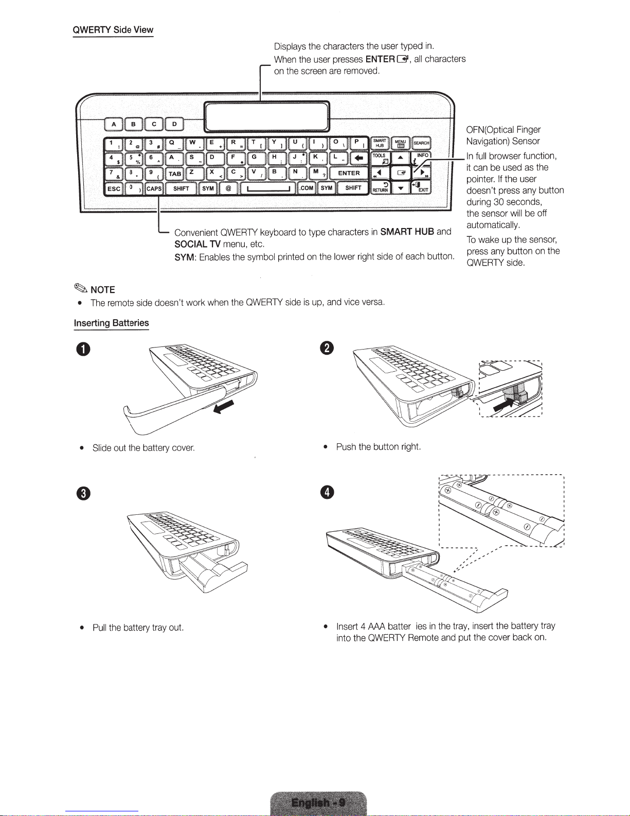
QWERTY
Side
View
Displays
the
When
the
on
the
user
screen
characters
presses
remo
are
user
the
ENTER
d.
ve
typed
01',
in.
characters
all
~NOTE
remote
The
•
Inserting
Batteries
0
doesn't work
side
Convenient
SOCIAL
SYM:
TV
Enables
when
QWERTY
etc.
menu,
symbol
the
QWERTY
the
keyboard
printed
side
to
is
type
on
up,
the
characters
rig
lower
vice
and
in
side
ht
versa.
SMART
each
of
.;.:---:-:--In
and
HUB
button.
OFN(Optical
Navigation)
browser function,
full
used
be
can
it
the
wake
any
If
press
seconds,
30
up
button
side.
will
pointer.
doesn't
during
the sensor
automatically.
To
press
QWERTY
Finger
n
Se
as
user
any
be
the
sor
the
button
off
sensor,
the
on
cover.
ery
batt
the
out
Slide
•
out.
ay
tr
battery
the
Pull
•
•
•
sert
In
into the
AAA
4
QWERTY
batter
in
ies
Remote
th
and
e
tray,
put
ert the battery
ins
cover back
the
tray
on.
right.
button
the
Push
Initial
1.
2.
~
~
Pairing
When
screen.
Press
The
TV
on
the
Keep
the
the
SYM
can
TV.
within
user
inserts
and
be
paired with only
20
inches(50
batteries into
TAB
buttons at
em)
the
QWERTY
the
same
one
QWERTY
between the
Remote,
time
for
remo
te.
QWERTY
"NEED
more
than
Start
Remote
PAIRING
2 seconds.
the
pairing process approximately
a
nd
the
TV.
PRESS
SYM+
TAB
"
will
be
displayed
30
seconds after turning
on t
he
Performing
1.
If
"RESET
2.
Press
completed
~
There might
screen.
3.
Follow
process must
Connecting the
the
QWERTY
the
OK"
MUTE,
the
(
I
I
I
~
l
Pairing
within
initial
Process
Remote
will
be
displayed
0,
MUTE and
4
seconds.
be
a slight delay between input
pairing
be
performed
Again
has
been
0
process
again.
on
on
within
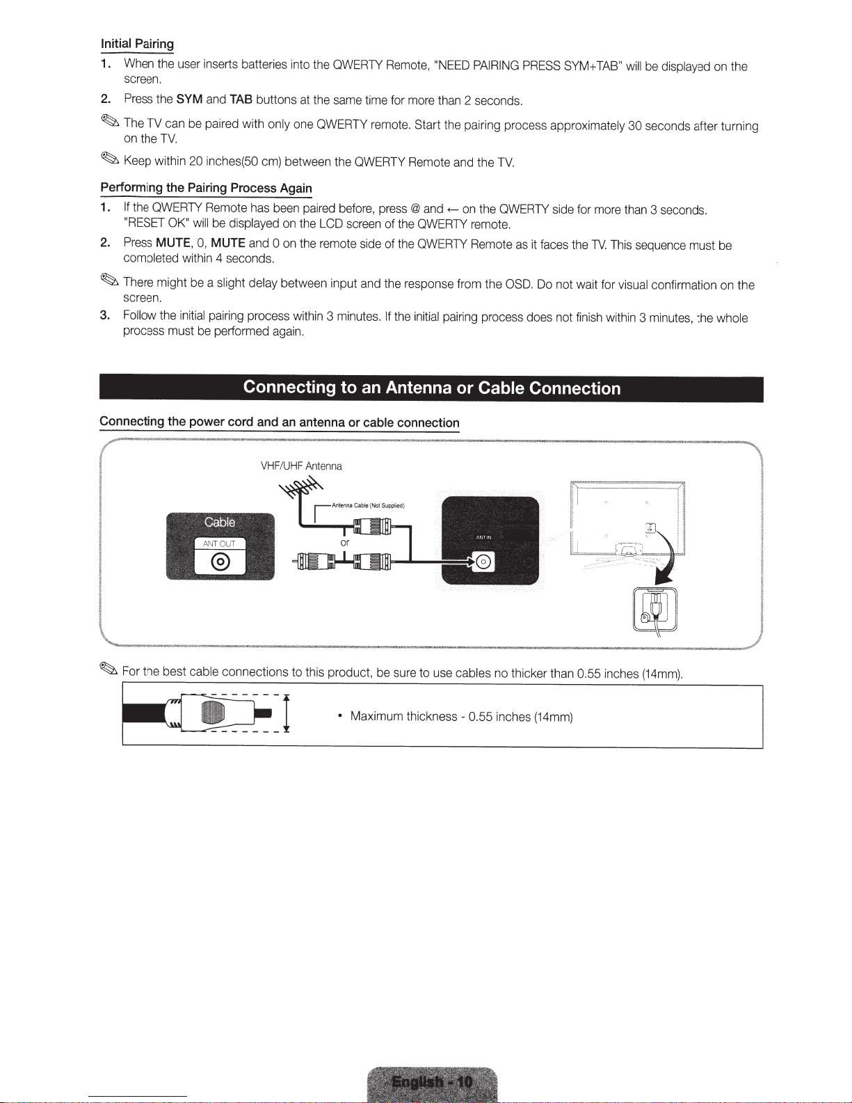
Connecting to an Antenna
power
cord
and
an
VHF
/
UHF
Cable
....
-
paired
the
LCD
the
remote
3
antenna
Antenn
before,
screen
side
and
minutes.
or
cable
a
press
@
and
of
the
QWERTY
of
the
QWERTY
the
response from t
If
the
initial
connection
<---
on
the
QWERTY
remo
te.
Rem
o
te
as
it
faces
he
OSD.
Do
pairing
process
or
Cable Connection
does
side
for
more
the
TV.
not wait for
not
finish
lf't=
-
--
·
--
!
i
-===-
than
This
sequence
visual
wit
hin
3
-·-
·-
---
='r
Q;
~
[W
3
seconds
must be
confirmation
minutes,
-.
-_-
:_-_
______
,,!
-
?.
!
·.'
the who
,,
..
..
1!
.
on
'l
the
le
!
I
l._"
· ·
·
"'M~oo-
•
-•"•
Mu-•
•
-•"
,_,._
-
•
·
----
Maximum thickness- 0.55 inc
hes
(14mm)
~••
-
•
u
When you turn the
press the
TV,
the
Plug
~
return to the previous step
~To
Before
~
Selecting the OSD
Language
Setting
Software
Selecting the usage
mode
Setting
POWER
is
Play
&
turning on the
up
Upgrade
the
Mode
Selecting
options for auto tuning
Selecting
memorizing channels
Enjoy
search
and
your
the
on for
TV
button.
C)
available only
ma
TV,
the Network
Clock
TV.
Play (Initial Setup}
&
Plug
first time, a sequence of on-screen prompts
when the
in
ke sure you have
Press the
Select
Set
your network set up information or want to set
network connection set
requirements and instructions, and the Net
You
When network connection settings are
Next
software upgrade.
to
~
Press the
twice.
Select
Press the
~
Source
Plug
the
the desired
up your network connection. Press the
can set
upgrade TV software. Your TV
to
"Software Upgra
This may take some tim
the
you
If
DST,
or
on to
butt
ENTERG,
done, press
you
If
~
and then press
set the date
ne setting the
do
Press the
appears on your
check both if you have both
you
If
~
to select
ec
sel
to
ENTERQ!I
both the
When done,
channel
The
more info
For
ess the
Pr
~
you want to watch a broadcast
If
Smart
ct
le
se
the e-Ma
in
Hub"
is set to
Play
&
co
T
or
.._
the network connection later using the Network menu.
up
T
or
.._
Use
Home
T
or
.._
selected
and th en p
select
then
ENTERG.
selected
or
T
or
.._
selection. Select
selected
Digital or
t the correct
Mo
gital
Di
select
search
ation, refer to
rm
ENTERG
Hub.
nu
TV.
sequence, select
the TV to an antenna or cable connection (Page
ted
ec
nn
on, then press
tt
bu
Screen Displa
(On
OSD
and refer to
now
up
upgrade
you want
If
"
de
button to
button
Auto,
your zon
sele
Manual,
ENTER
me. Use the
ti
Date
button to
Cable,
cable
st
and
ill
w
to
eference Features
(Pr
depending on network status.
e,
select
Store
mode.
select
to
go
you'll
ENTER
ss
re
and then press
e,
ether
wh
ct
you'
Then, use the number
G .
Time
and
select
nnected.
co
go
you'll
and then press
,
Analog
cable signal
systems use
systems.
og
Anal
and the p
,
Next
start automatica
Channel-->
on at any time to interrupt the m
butt
will
Hub
Smart
l.
a
Previous,
the
complete,
will automatically
Home
Demo
or
Auto
the
to
On
G.
turn
to
the
to
go
ll
~
or
..,..
select
,
Cable,
or
Air
and then press the
Next,
the
to
format
re
y. This can take up to
ll
ogram,
pr
start. For
configuring basic settings.
in
assist
will
and then press
button.
Q!l
ENTER
language.
y)
button to start.
ENTER
wo
later, select
Use,
mode
Manual,
Time
button to move
G
select
later,
it
to
"Network menu" in the
rk Connection section
Software Upgrade is
upgrade, if your TV need a
Skip.
the
--. Support
and then press the
Zone
the
DST
Date
Next,
Menu)
retail environments.
for
is
and then press
DST
and
Zone
Time
ENTER[31
(Daylight Savin
and
and then
.
Time
ons
butt
be
and then press
pr
On
ess
ENTER
ble System
Ca
screen. Use the
ENTERQ!I.
STD, HRC,
-
STD. Select
ENTER
ss
Program
Auto
Close.
select
e detai
mor
or
the correct
G.
the e-Ma
in
you
If
in
d
le
ENTER
Skip
F
in
G.
you
If
We suggest you
.
e-Manual
this manual
of
available. Select
more information, refer
or
e-Manual.
the
ENTER
Q!l
ENTER
use the
n,
DST
the
Time) on or
gs
Select
the
or
Select
sc
or
.._
fields.
screen.
scree
screen.
tween entry
ENTER
ENTER
Use the
IRC
30 minutes.
emo
wa
formation, refer
Q!l.
button.
[31
.._
or
.._
- and th en
ble sig
ca
l.
a
nu
rization process.
nt to enjoy
tu
To
.
0)
1
not know
do
sk
up
for set
(Page 17).
button
twice.
G
Time Zone
T
or
.._
reen, press,
. When
off
Time,
or
Date
n
tto
bu
T
When
G .
eck
A ch
n
ca
You
tt
bu
T
or
tton
bu
T
ess
pr
t for
ma
for
l
na
Hub,
Smart
"Smart
to
rn
to
on
on
ip
...
Play
&
Plug
Rerun
to
Want
You
If
Plug
Play
&
volume
--.
aga
at home
in
bar on
System
MENU[]]]
~
ul
sho
You
NOTE
~
change the TV's setting from
To
•
When you see the
-->
Plug
do
d
Play
&
Store
e scree
th
ENTER
--.
although
to
Demo
press a
n,
Q!l
you did
Home
nd
shop.
in
when not in
Use
hold the
MENU
Plug
tt
bu
Play,
&
on on
press the
e TV for 5 sec.
th
volume button on the TV.
Connecting to an
AV
Device
Using an
We
Available
HDMI
recommend using the
devices:
~
HDMIIN
•
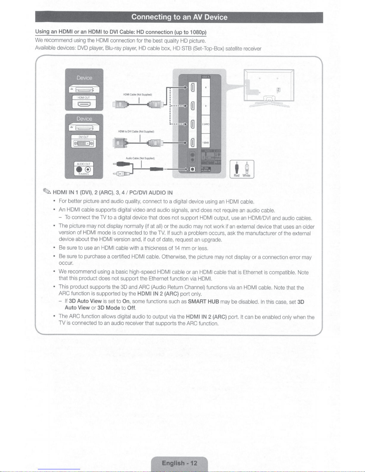
For better picture and audio
•
An
HDMI cable supports
-
To
connect the
•
The picture may not
version
device about the
•
Be sure to use
•
Be sure to purchase a certified HDMI cable.
occur.
•
We recommend using
that this product does not support the Ethernet function via HDMI.
•
This product supports the 3D and ARC (Audio Return
ARC function is supported by the
-
If
30
Auto View
•
The ARC function
TV
is
connected to
or
an
HDMI
DVD
player,
1 (DVI),
of
HDMI
Auto View
or
to
DVI
Cable:
HD connection
HDMI
connection for the best quality HD picture.
Blu-ray
2 (ARC),
TV
mode
HDMI
an
HDMI cable
is
3D
allows digital
an
player,
HD
cable box, HD STB (Set-Top-Box)
3,
4
I
PC/DVI AUDIO
quality,
connect to a
digital
video
and audio
to a
digital device that does not support
display normally
is
connected to the
version and, if out of date, request
a basic high-speed
set to
On
Mode
to
audio receiver that supports the ARC function.
(if at
all)
with a thickness of
HDMIIN
,
some functions such as
Off.
audio to output via the
(up
IN
digital device using
signals,
or the audio may not work if
TV.
If
such a problem
14
Otherwise, the picture may not
HDMI cable or
2 (ARC)
port
to
1080p)
satellite
an
and does not require
HDMI output, use
occurs, ask the manufacturer of the
an
upgrade.
mm or
less.
an
HDMI cable
Channel) functions via
only.
SMART HUB
HOMI
IN
may be
2 (ARC)
receiver
t
g
Red
White
HDMI cable.
an
audio
an
HDMI/DVI
an
external
display
that
is
Ethernet is
an
HDMI cable.
disabled.
port.
It
can be
cable.
and audio cables.
device that uses
or a connection error may
compatible.
Note that the
In
this case, set
enabled only
an
older
external
Note
30
when the
English
·12
a
Using
Available
~
~
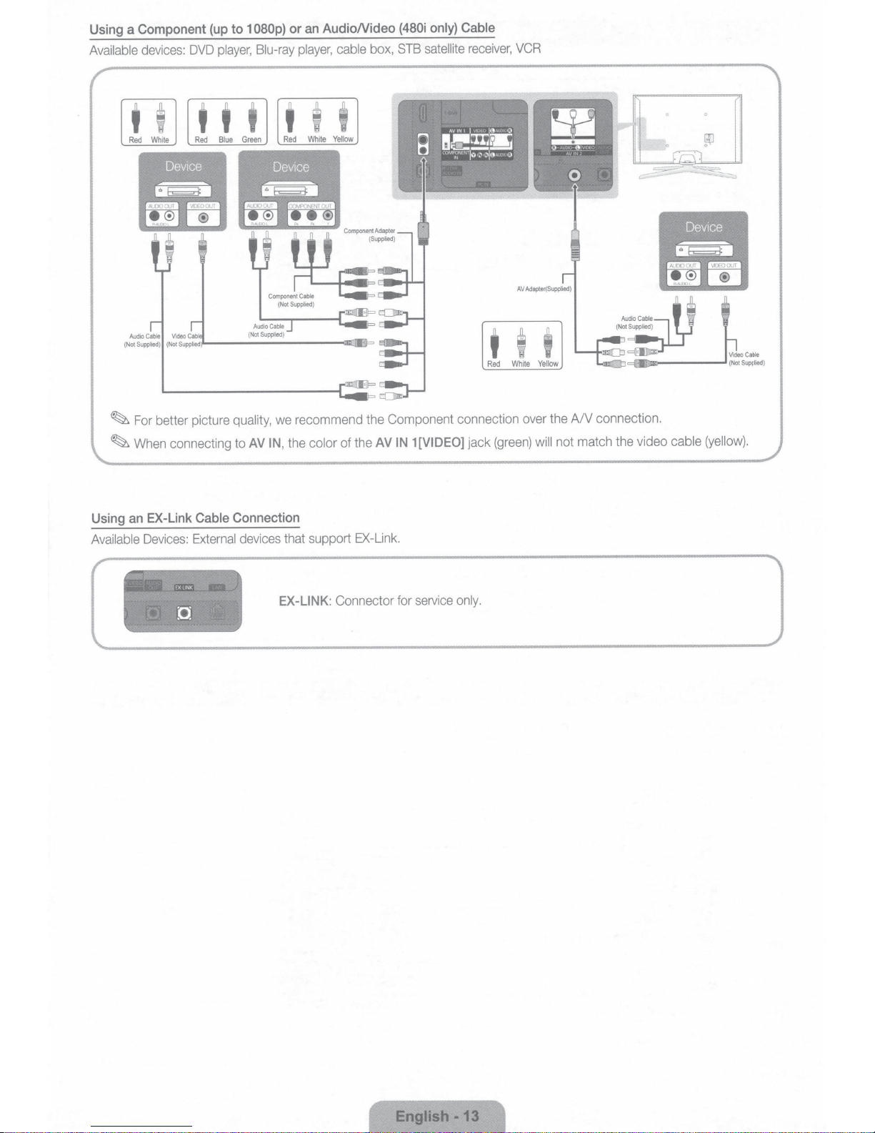
Component
devices:
For
When
DVD
better picture
connecting
to
(up
player,
t t
quality,
to
080p)
1
Blu-ray
t
AV
only}
box,
AV
(480i
STB
1
IN
satellite
[VIDEO]
AudioNideo
an
or
cable
player,
I I
t
recommend the Component connection
we
the
of
color
the
,
IN
Cable
receiver,
t
Red
jack
VCR
t
White
over
(green)
I
Yellow
A/V connection.
the
not match
will
video cable
the
(yellow).
EX-Link
an
Using
Available
Devices:
:~~~:.:.:r~~·!!t:~::~~
~
:·
0
• •
"''
';.,
"'.t;/t~~~lii~""~~LJ,'!-i/£'t'
~J:i't/iflit,;,";J:.~•
Cable
External
•'
"'~~4'"~
Connection
devices
l
Tl1
that support
EX-LINK:
EX-Link.
Connector
for
service
only.
English
-13
Using
an
Available
Connecting to an Audio Device
Optical
devices: Digital Audio System, Amplifier,
(Digital)
or
an
Audio
(Analog)
Cable
Connection
DVD
Home Theater
[(9J
AUDIO
OUT
DIGITAl
iAUOIOO..JT
OPTICALJ
Aud10
Cable
(
Not
~
~
DIGITAL
•
•
•
AUDIO
•
•
AUDIO OUT
When you connect a Digital Audio
of both the TV and the system.
5.1
CH (channel) audio
When the receiver (Home Theater)
the TV
is
receiving a DTV signal, the TV
source is a digital component such as a
receiver and you connected it to the TV via HDMI, you will
receiver. If you want to hear
cable box
When connecting, use the
When you connect
volume level with the amplifier's volume control.
I
STB satellite
OUT:
Connects to the audio input jacks on your amplifieriDVD Home Theater.
(OPTICAL)
System to the
is
available when you connect the TV to
is
set to on, you can hear sound output from the TV's optical jack. When
will
DVD
5.1
CH
audio, connect the digital audio out jack from your
receiver directly to
appropriate connector.
an
audio amplifier to the
Supplied
)
send
player
an
amplifier
AUDIO
D.
DIGITAL
5.1
AUDIO
OUT
an
external device supporting
CH sound to the Home Theater receiver. When the
I
Blu-ray player
only hear 2
or
Home Theater.
OUT
jacks, decrease the volume of the TV and adjust the
I
~~
(OPTICAL)
cable box I
CH
audio from the Home Theater
jack, decrease the volume
STB
(Set-Top-Box) satellite
DVD
I
Blu-ray player
Red
5.1
White
CH.
I
Using
an
HDMI
~Your
PC may not support
cable
or
an
HDMI
to
DVI
an
HDMI connection.
Connecting to a PC
cable
or
aD-sub cable
.
I
QJ
~
....
'
.
_-.:;
__
_
'
English
·14
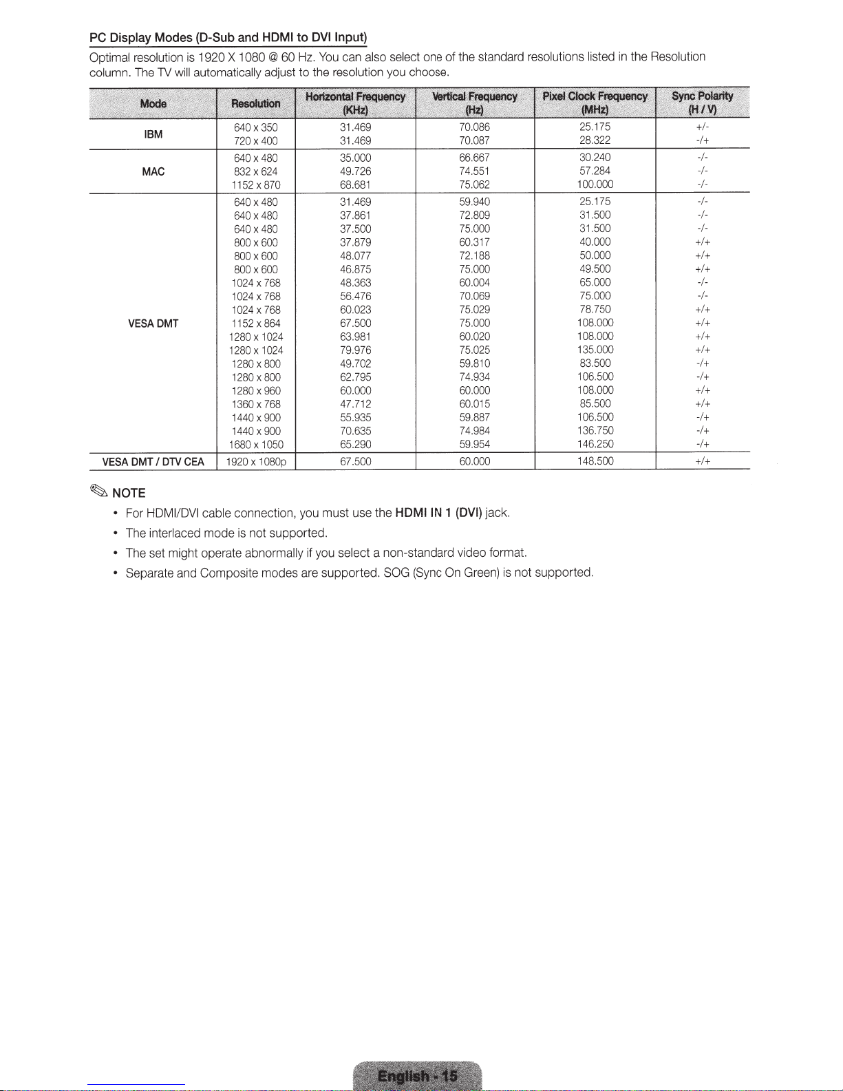
PC Display
Optimal
column.
resolution
The
Modes
will
TV
19
20
X
and HDMI
10
(D-Sub
is
automatically
80
60
@
adjust
to
Hz.
to
DVI
You
resolution
the
Input)
can
also
select
u
yo
one of
choose.
the
standard
resolutions
sted
li
in
ution
l
Reso
e
th
NOTE
~
•
•
•
•
IBM
MAC
VESADMT
HDMI
or
F
nterlaced
i
The
set
e
Th
te
Separa
640x350
400
X
720
480
X
640
624
X
832
x870
1152
480
640x
480
X
640
480
X
640
600
X
800
600
X
800
600
800x
1024x768
4x768
02
1
768
X
1024
864
X
1152
1024
X
1280
1024
X
DVI
/
ble
ca
mode
1280
1280
1280
1
1
1440x
1440x
1680
0
80
X
0
80
X
960
X
280
768
X
360
900
900
1050
X
connectio
not supported.
is
might operate abnorma
Composite
and
modes
n,
yo
y
ll
a
31.469
469
.
31
35.000
49.726
68.681
.469
31
37.861
37.500
879
.
37
48.077
46.875
48.363
56.476
60023
67.500
1
63.98
976
.
79
702
.
49
795
.
62
60.000
12
47.7
55.935
70.635 74.984
290
.
65
HDMIIN
he
t
use
u must
a non-standard
lect
se
you
if
(Sync
supported.
re
SOG
1
On
70.086
087
.
70
66.667
74.551
75.062
940
.
59
809
.
72
75.00
317
.
60
1
72.
000
.
75
60.004
069
.
70
029
.
75
75.000
020
.
60
025
.
75
59.810
74.934
000
.
60
015
.
60
59.887
954
.
59
(DVI)
video
Gre
0
88
jack.
format.
en)
is
not
25.175
28.322
30.240
57
00
1
25.
31
31.500
40
50
49
65
75.000
78
08.000
1
08
1
35
1
83.
06
1
108.
85.500
106
136
46
1
supported.
.284
000
.
75
1
500
.
000
.
00
.0
00
.5
000
.
750
.
000
.
000
.
50
500
.
000
.500
750
250
.
+1-
-1+
-1-
-1-
-1-
-1-
-1-
-I+I+
+I+
+I+
-1-
-1+I+
+I+
+I+
+I+
+
0
-1
1+
-
+I+
+I+
-1+
-I+
-1+
Changing the
Input Source
Edit
Name
Source
Use
to select
source such
player
I cable box
•
TV
I
Component
HDMI2
I
USB
I
1.
Press
the
remote.
2.
Select
a desired
~
You
can only choose external devices that
connected to the
be
highlighted.
~In
Source,
TV
or
as
a
DVD
I
I
HDMI3
AIIShare
SOURCE
PC
an
external
player
STB
I
I
HDMI4
external
TV.
satellite
PC
I
button
In
Source,
input
I
Blu-
receiver.
HDMI11DVI
I
AV1
on
input
always stays act
ra
y
I
I
AV2
your
source.
are
connected inputs
iv
ated.
will
Edit Name
source.
Source.
•
~If
To
The
VCR
I
AV
Receiver
Devices
the
dev
input
source
you
have
access
port with
to enter a device
~
If
you
have
port with
Edit Name
~
If
you
connected
port with
under
Edit Name
Edit
Favorites
In
Source,
Favorites.
Favorites.
You
lets
you
associate
Edit Name,
following
DVD
I
Cable STB
I
Game
I
TV
I
IPTV
i
ce
connected to
selection
connected a
an
HOM
name.
connected a
an
HOM
to enter a device
an
HDMI
press
the
TOOLS
can
set
selections
I
Camcorder
I
Blu-ray
the
easier.
PC
I
cable,
PC
I
to
DVI
an
AV
device to the
to
DVI
to
enter a
button to select
an
external
a
device
name
press
the
appear
under
I
Satellite STB
I
I
HD
DVD
input jacks to
to
the
HDMIIN
se
lect
PC
to
the
HDMIIN
cable,
select
name.
ca
bl
e,
select
de
v
ice
name.
input source
to
TOOLS
Edit Name:
I
PVR
PC
I
DVI PC
I
make
under
DVI PC
HDMIIN
DVI
Edit
an
inpu
button
STB
DMA:
Name
your
1
(DVI)
Edit
Name
1
(DVI)
under
1
(DVI)
Devices
as
a
t
I
In
I
DVI
Information
You
can
see
detailed
device.
Refresh
In
Source,
t
he
connected
TOOLS
If
the
bu
tton to
devices.
information
external
se
d
ev
le
ct
abo
ut the
i
ces
ar
e not displayed, press
Refresh,
th
en
selected
search
ex
te
for the
rnal
set
can
You
connection.
Network
You
This
you
Most
point
Your
•
•
If
Connection
connect
can
LAN
The
supports
TV
video
play
wireless
AP
or
compatible
is
TV
Authentication
Encryption
select
you
Port
(typically
(WPS2Mixed)
certification
specifications.
TV
your
up
your
the
on
the
a
over
network
a
Mode:
Type:
High-throughput
Pure
your
on
so
Wireless
-
to
TV
Wall
Cable
LAN
IEEE
IEEE
systems
wireless
with
OPEN,
WEP,
or
AP
it
that
your
(router
(Not
802.11
802.11
incorporate
IP
following
the
TKIP,
wireless
access
can
through
LAN
IP
Wireless
DHCP
having
Supplied)
and
a/big
connection,
big
Sharer-
security
SHARED,
AES
(Greenfield)
router,
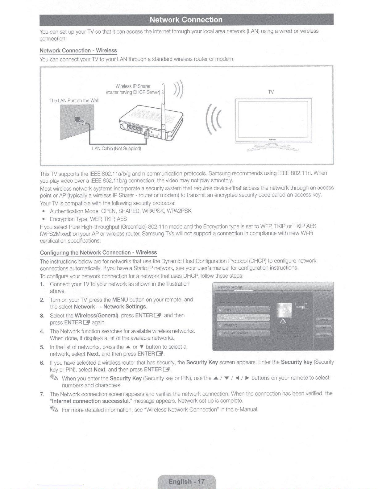
Network Connection
wireless
protocols.
may
that
transmit
to
and
not
will
your
router
not
requires
the
support a
Internet
the
standard
a
Sharer
Server)
n communication
video
the
modem)
or
system
security
a
router
protocols:
WPAPSK,
802.11
Samsung
WPA2PSK
mode
n
TVs
through
area
local
modem.
or
Samsung
smoothly.
play
devices
encrypted
an
Encryption
connection
network
(LAN)
recommends
access
that
security
set
is
type
in
using
TV
using
network through
the
called
code
WEP,
to
compliance
wired
a
IEEE
TKIP
with
or
802.11
access
an
TKIP
or
new
wireless
When
n.
an
key.
AES
Wi-Fi
access
Configuring
instructions
The
connections
configure
To
Connect
1.
above.
on
Turn
2.
select
the
the
Select
3.
ENTER
press
Network
The
4.
done,
When
list
the
In
5.
network,
have
you
If
6.
PIN),
or
key
When
~
numbers
Network connection
The
7.
Internet
"
For
~
Network
the
are
below
automatically.
network
your
to
TV
your
press
TV,
your
Network
Wireless(
again.
G'
function
displays
it
networks,
of
Next,
select
selected
Next,
select
enter
you
characters.
and
connection
detailed
more
Connection
networks
for
have
you
If
connection
network
your
MENU
the
Network
---+
General),
searches
of
list
a
the
press
then
and
wireless
a
then
and
Security
the
screen
successful."
information,
-
that
a
for
as
button
Settings
press
available
for
available
the
or
.&
press
router
press
Key
appears
Wireless
use
IP
Static
a network
shown
on
.
ENTER
button
'Y'
ENTER
has
that
ENTER
(Security
and
message
"Wireless
see
Dynamic
the
uses
that
illustration
remote,
then
and
networks.
see
network,
the
in
your
G',
wireless
networks.
select
to
G'.
security,
the
G'.
PIN),
or
key
network
the
verifies
appears.
Network
Network Connection"
Configuration
Host
user's
your
DHCP,
and
a
Security
use
manual
these
follow
Key
.&
the
connection.
is
up
set
Protocol
for
steps:
appears.
screen
.,..
I
T
I
When
complete.
e-Manual.
the
in
(DHCP)
configuration
Enter
buttons
~
I
connection
the
configure network
to
instructions.
Security
the
your remote
on
been
has
(Security
key
select
to
verified,
the
English.
-17

Network
There are two main ways to connect your
illustrated below:
Connection
The
Modem
The
LAN
Port
Port
on
on
the
-
Wired
the
Wall
Modem
Wall
Cable
(Not
TV
to your network using cable, depending
External
I
VDSL
Cable
Modem
I
Cable
(Not
Supplied)
TV)
LAN
Cable
(ADSL
Supplied)
LAN
on
your network setup. They
TV
(Not
Supplied)
TV
Rear
Rear
are
Panel
Panel
~A
network
Configuring
Most home networks use the Dynamic Host Configuration
that support
Internet
To
configure your network connection for a network that uses
follow these steps:
1 .
Connect your
illustrations above.
2.
Turn on your
then select
Settings
3. Select
again.
4.
The Network Connection screen appears, and verifies the
network connection. When the connection has been verified, the
Network set up
~
If
your
select
Address, Subnet Mask,
~
For more detailed information, refer to
speed of lower of than
the
Network
DHCP
so you don't have to enter them manually.
TV
TV,
Network-----+
screen
Wired
,
press
TV
cannot acquire network the connection values automatically or if you want to set the connection manually,
IP
Settings
Connection
automatically provide the
to your network
press the
Network
will
appear.
ENTERG,
is
completed.
on the network connection screen. Set
Gateway,
10
Mbps
is
-
Wired
IP
address, subnet mask, gateway, and
as
shown
in
MENU
button on your remote, and
Settings.
and then press
The
and
DNS
"Wired Network Connection"
not supported.
one of the
Network
ENTERG
Server
Protocol
DHCP,
Internet
manually.
(DHCP)
"Internet
Protocol
to configure network connections. Home networks
DNS
values your TV needs to access the
connection
Setup
in
the e-Manual.
successful.
to
Manual.
"
message appears.
You
must enter the
IP
English
-18
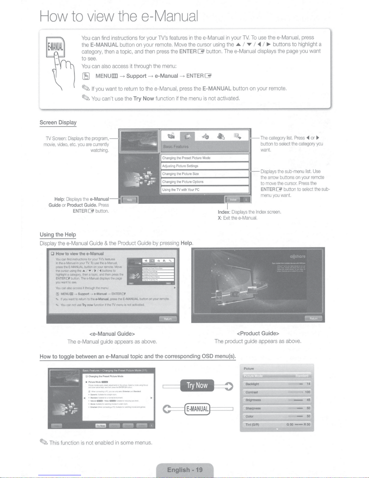
How
to
view
the
e-Manual
Screen
Screen:
1V
movie,
Guide
Display
video,
Help:
or
Displays
you
etc.
Displays
Product
ENTER
can
You
E-MANUAL
the
category,
see.
to
can
You
MENU
(E)
you
If
~
You
~
program,
the
currently
are
watching.
e-Manual
the
Guide.
button.
131
instructions for
find
then
access
also
liD
want
use
can't
Press
button
a topic,
Support
-t
return
to
the
on
and
through
it
to
Try
your
your
then
-t
the
Now
features
TV's
remote.
the
press
menu:
the
e-Manual
e-Manual,
function
Move
ENTER
-t
press
the
if
thee-Manual
in
cursor
the
G
the
menu
G
E-MANUAL
is
ENTER
thee-Manual,
use
To
TV.
your
in
..,..
I
,..
I
T
I
•
the
using
button. Thee-Manual displays
remote.
your
on
button
not activated.
category
The
button
want.
Displays
arrow
the
move
to
ENTER
menu
screen.
Index
the
Displays
Index:
thee-Manual.
Exit
X:
buttons
the
select
to
sub-menu
the
buttons
cursor.
the
button
131
want.
you
to
page
Press
list.
the
press
highlight
you
~
category
list.
your
on
Press
select
to
want
~
or
you
Use
remote
the
the
a
sub-
Using
Display
0
to
How
the
the
How
You
!he
In
press
cursor
the
highlight
ENTER
you
You
MENI.I£1D-->
fSl
.,. U
You
.,.
--~-
--
toggle
Help
e-Manual
to
can
e-Manual
the
13'
want
can
you
can
Guide
e-Manual
the
view
instructions
find
E·MANUAL
using
category,
a
button.
see.
to
access
also
want
not
~~
your
in
the
The
Support-
return
to
Try
use
TV.
button
I
..o.
then
e·Manual
through
it
to
now
~~-~-~
-
your
for
TO
on
I • I
Y
topic,
a
the
a-Manual-
function
<e-Manual
Thee-Manual
between
0 Changing
Picture
•
Pk:tlnmoclesBOPfVpteaet~IDtnepiC!um_SelectamooelJSnQtne<.O
HOdQlwnar,.,keys.and!henpresa!haEI'fl'ERI3'txJnon
(ll'MP!eomactlllgaPC.VCJOcar'lon!ysfidEntmlalr>iii'>:IStandan:l
•Dynamk::Suital*tklrabngt1room
•Stllndard
<4
•Naturai
•MoYie:Sulablalcr-d'w>grTOYIIIor>adll1lJOOm
• Entertaln(M'w!nllOI'll"eC!ngePQ
Product
the
&
features
TV.'s
a-Manual.
the
use
the
a-Manual,
your
buttons
<I
and
displays
menu:
·~-
remote.
then
the
~
~-
Move
to
!he
press
page
the
ENTERQI'
theE-MANUAL
press
menu
TV
Guide>
appears
guide
e-Manual
an
Mode
Preset Picture
the
G!DII
Mode
&id:ableloranom'lllli~
ReW<_SutiCIIIIIor~II'/Ostr.-1
__
.SulaliebW'illehingiT()IIIII6anagatr.
not
iS
--=
Guide
activated.
~.-..
~
as
topic
on
button
·~~--....,....--~~~~
above.
and
pressing
by
.
remote
your
~
~
corresponding
the
•
Help.
OSD
product guide
The
menu{s).
<Product
Guide>
appears
as
above.
some
~
This
function
not enabled
is
in
menus.
English
-19
1.
Select
corresponding
2.
To
return
button.
Try
Now,
to
menu(s)
the
e-Manual
if
you
Method 1
want
to
.
screen,
execute
press
the
the
E-MANUAL
1.
2.
Press
the
"Do
you
and
then
appears.
To
return
button.
Method 2
ENTER
G
button
want to execute
press
the
ENTER
to
the
e-Manual
when
this?"
G
button.
screen,
a topic
appears.
The
press
the
is
displayed.
Select
Yes
OSD
window
E-MANUAL
,
•
...
rEI
Try
to
Home:
Zoom:
Index:
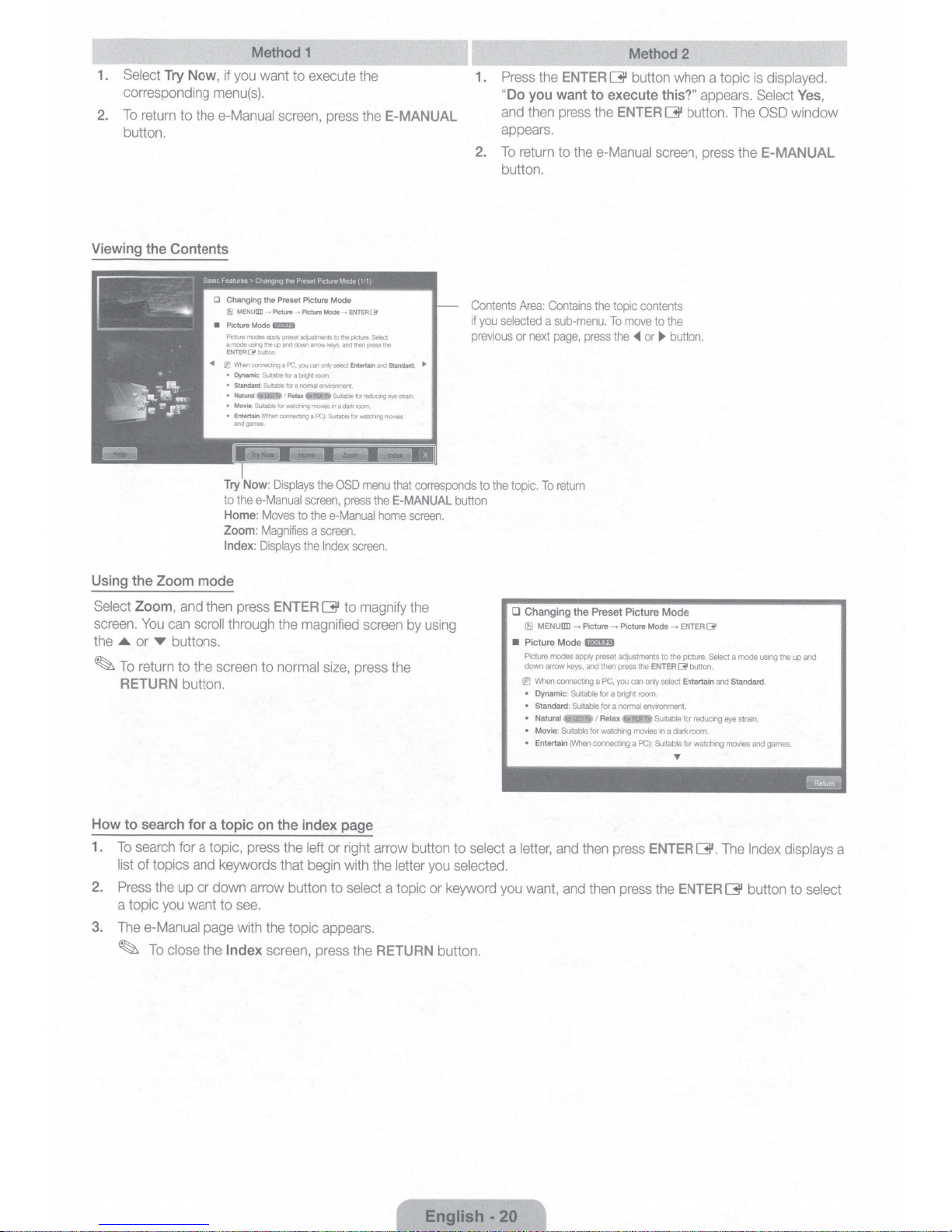
Using the Zoom mode
Select
Zoom,
and
then
screen.
the
~
You
..a.
or
T
To
return
RETURN
can
scroll
buttons.
to the screen to
button.
~
MENU
aD
-+
P
ic
Mode
modes
us1ng
(31
button
coonecting
:
SUitable
:
Suitable
(INhen
games
ture
f&l!5J
apprt
the
up
.
Suitable
for
connecting
.
.
Displays
Picture
Picture
a
mode
ENTER
When
•
Dynamic
•
Standard:
•
Natural
•
Movie
•
Entertain
and
thee-Manual
Moves
Magnifies
Displays
press
ENTER
through the
normal
__.
Pictu
preset
adjustments
and
down
arrow
a
PC
,
you
can
f
or
a
bnght
for
a
normal
I
Relax
watching
mov
a
screen,
to
the
a
the
magnified
re
Mode
to
keys.
only
select
room
.
enVIronment
Suitable
i
es
in
a
PC)
:
Suitable
the
OSD
e-Manual
screen
Index
G
size,
---+
E
NTER
the
picture
and
then
Entertain
for
dark
room
for
watch1ng
press
.
screen.
to
magnify
press
(31
.
Select
press
the
and
Standard
reducing
eye
.
movies
menu
that
the
E-MANUAL
home
screen
the
.
•
srram
.
corresponds
screen
the
by
using
.
Contents
if
previous
button
Area:
you
Contains
selected
a
or
next
to
the
topic
.
To
D Changing the Preset Picture Mode
[!iJ
MENU[]]]
•
Picture Mode
Picture
down
arrow
(l'J
When
•
Dynamic:
•
Standard
• Natural
• Movie:
•
Entertain
sub-menu.
page
,
press
return
~
Picture - Picture
ll'!l!mm
modes
apply
keys,
and
connecting
Suitable
:
Suitable
Suitable
for
(When
connecting
the
to
To
the
preset
then
a
PC,
for
a
for
a
I
Relax •
watching
pi
c co
mo
ve
..
or~
adjustments
press
the
you
can
only
bright
room.
normal
environment.
movies
a
PC}:
ntents
to
the
button.
Mode
~
to
the
ENTER[]'
select
Suitable
in
a
Suitable
ENTER[]'
picture.
butlon.
Entertain
for
dark
room.
for
T
Select
reducing
watching
and
eye
movies
a
mode
Standard.
strain.
and
us1ng
games.
the
up
and
How to search for a topic
1.
To
search
for a topic,
list
2.
3.
of topics
Press
a topic
The
e-Manual
~
the
you
To
close the
up
and
or
want
page
on
the index page
press
the
left
keywords that
begin
down arrow button to
to
see.
with
the
topic
Index
screen,
press the
or
right
with
select
appears.
arrow
button
the
letter
a topic
RETURN
to
select a
you
selected.
or
keyword
button.
English·
you
20
letter,
want,
and
and
then
then
press
press
ENTER
the
ENTER
G.
The
G
Index
button
displays a
to
select
If
the
TV
seems
to
have a problem
section
in
thee-Manual.
Samsung
The
There
The
The cable/set top box
c
ontrol
o
ff,
customer
TV
won't
turn
is
no
picture/video.
remote co
or adjust the
ntrol
doesn't
on.
turn
volum
If
none
service
at
does not wo
rem
ote
the
TV
on
e.
, first
review
of
the
troubleshooting tips
1-800
-SAMSUNG.
•
•
•
• Check the cable connections.
• Set the video outputs
•
•
• Reboot the con
rk.
• Repl
•
•
• P
or
Troubleshooting
this list of p
Make
sure
the
Make
sure
the
Try
pressing the
remote.
TV
to match the
HDMI,
Make
Be
remote
power cable.
poles(+/
Clean
Try
u
If
the
and
external
it
should
sure your
sure
to
sele
control.
ace
the remote control batter
-)
in
the
sensor's
pointing the
ro
gram the Cabl
ser manu
al for the S
ossible
problems
apply,
visit
"www.samsung.com,"
AC
power cord
wall
outlet
POWER
TV
turns
devices.
of
TV
input connection
be
connected to
connected
ct
the
correct input s
nected
the correct direction.
transmission window
remote
e/Se
t remote contro
AMSUNG
is
is
working.
button on
on,
refer
to "
Re
your
external devices
devices
device
by unplugging
directly at the
TV cod
and
solutions. Also review the
and
securely
move and
s.
an
ies
plugged
the
TV
to make sure t
Remote
For exa
are powered
ource
control does not work" below.
reconnect all cables connected to
(Cable/Sat Box,
mpl
HDMI
input
by
pressing
and
. Ma
ke sur
on
the
TV
from
5- 6
l to operate the
e.
in
e, if an exte
on
the TV.
on.
then reconnecting the device's
e the batteries are installed with their
remote.
feet
Troublesh
then
click
to the
wall
he
problem
DVD, Blu-ray etc)
rnal
devi
the
SOURCE button
away.
TV.
Refer
to the C
on
Supp
outlet
and
is
ce's output
ooti
ort,
the
not the
on
able/Se
ng
or
call
TV.
the
is
the
t
~
This
TFT
LED
panel
there may
produc
~
To
---.
Support
keep
be a few
t.
your
TV
---. Downloads
srs@
TheaterSound
•
Excellent
broadcasts
• 3D: T
• SMART
-
-
- Gives
- Lets you customize yo
AilS
•
• Anynet+(HDMI-
TV
Digital
without a cable b
his exciting
HUB: Your
Provides
Lets you control
hare
's remote.
diverse entertainment
you easy
rM:
AilS har
uses a panel
bright or dark
in
optimum conditio
).
HD
Interface &
new fea
Gatew
your
access
e ™ connects your
CEC): All
Networking: Usin
ox
ture ena
ay to a
entertainment
to diverse
ur
TV
ows you to co
consisting of sub p
pixels
on
the scr
n,
upgrade to the latest firmware
[I]
DOLBY.
DIGITAL PLUS I
PULSE I
or S
TB (Set-Top
bles you
ll your
by
to v
content, integrat
choices.
life
with
App
s,
with more being added ev
groupin
g a
TV and compat
ntrol all conne
iew
nd sort
ixels
which require sophisticated technology
een.
These
pixels
will
on
License
~db
2.
List of Features
g its
built-in
HD digit
-Box) s
atellite receive
30
content.
ed
in one place.
an easy
-to-us
ing Apps to yo
ible Sa
cted Samsung devices that suppo
al
tun
r.
e,
user
friendly
ery day.
ur taste
m sung mobile phones/devices through a netwo
to produce. Howev
have
no
impact
on
the performance of the
the Samsung
web site
by
USB (samsung.com
DIVX
0+Digital
Out
er, you can view non-subscription
Ul.
.
rt Anyne
HD
t+ w
ith
your Samsung
er,
N
HD
rk.
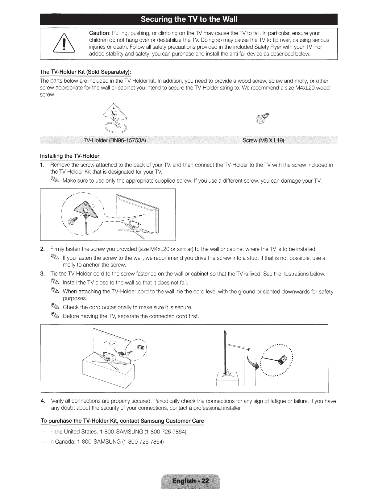
Securing the
TV
to the Wall
Caution:
children
injuries
added stability and safety, you can purchase and install the anti
The
TV-Holder
The parts below are included
screw appropriate for the wall
screw.
Installing
1_
Remove the screw attached to the back
the 1V-Holder Kit that is designated for your
~
Kit
(Sold
the TV-Holder
Make sure to use only the appropriate supplied screw. If you use a different screw, you can damage your
Pulling, pushing,
do
not
hang over
or
death. Follow
Separately):
in
the
1V
or
cabinet you intend
or
or
all
Holder kit.
of
your
climbing on the
destabili
safety precautions provided in the included Safety Flyer with your
1V.
ze
In
addition, you need
to
secure the 1V-Holder string to. We recommend a size
1V,
and then connect the 1V-Holder to the
1V
may cause the
the
TV
Doing so may cause the
to
provide a wood screw, screw and molly ,
1V
fall
to
fall.
1V
device
In
particular, ensure your
to tip
over,
causing serious
as
described below.
M4xl20 woo
1V
with the screw included
1V. For
or
other
TV.
d
in
2. Firmly fasten the screw you provided
~
If
you
fasten
the
screw to the wall,
molly
to
anchor
the
screw.
to
the scr
3. Tie the 1V-Holder cord
~
Install the TV close to the wall so that it does not fall.
~
When attaching
purposes.
~
Check
the
cord
~
Before moving the
4. Verify a
To
purchase
any
ll
connections are properly secured. Periodically
doubt
about the secu
the
TV-Holder
the
occasionally
TV,
ew
TV-Holder cord
separate the connected cord first.
rity of
your connections, contact a professional installer.
Kit,
contact
(size
M4xl20
we
fastened on the wall
to
to
make sure it is secure.
Samsung
or similar)
recommend you drive the screw into a stud.
the wall, tie
Customer
to
the
wall or cabinet where the
or
cabinet
the
check
so
that the
cord
level with
the connections for any sign
Care
the
1V
is to be installed.
If
that is not possible , use a
1V
is
fixed. See the illustrations below.
ground
or
slanted downwards for safety
.
········
...
(~)
. .
·.
of
··
..·
..
.....
fatigue or failure. If you have
In the United States: 1In
Canada: 1-800-SAMSUNG (1-800-726-7864)
800
-SAMSUNG (1-
800
-726-7864)
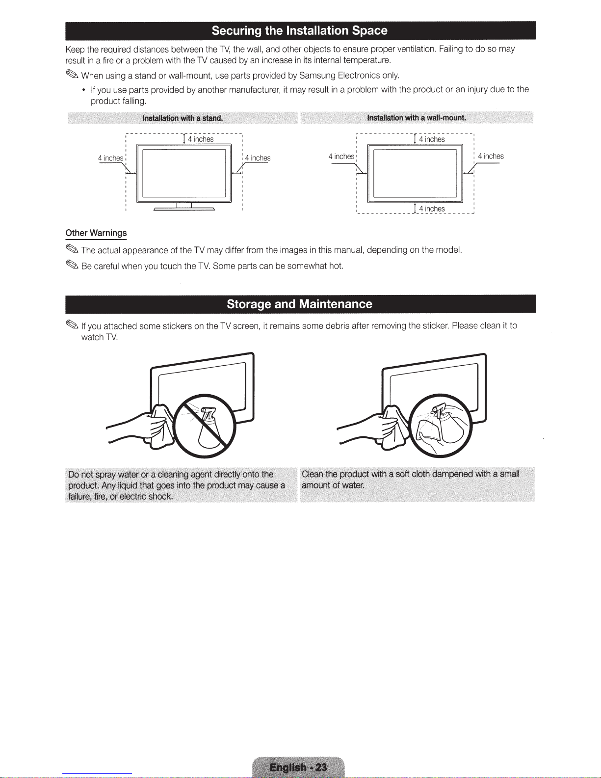
required
the
Keep
fire
a
in
result
using a stand or wall-mount,
When
~
you
If
•
product
4inches:
~
Warnings
Other
~The
~
actual appearance of the
care
Be
distances
problem
a
or
parts provided
use
.
ling
l
fa
------------T
you
when
ful
between
with
touch
Securing the
TV,
the
caused
TV
the
use
another
by
------
hes-
inc
4
may
TV
Some
TV.
e
th
Installation Space
and
wall,
the
increase
an
by
parts provided
manufacturer,
parts
the
can
differ from
other objects to
its
in
Samsung
by
result
may
it
images
be
in
somewhat
ensure
temperature.
internal
ctronics
Ele
a problem with the product or
in
'
4inches:
______________
,
manual,
this
hot.
Storage and Maintenance
ventilation.
proper
only.
depending
on
4 inc
~
~
the
Failing
an
s
he
_____
ns;~~s
model.
may
so
to do
injury due to t
ches
in
: 4
'
~
_
he
~
you
If
watch
attached
TV.
some
stickers
on
the
TV
screen,
it
s some debris after
in
rema
removing
the s
cker.
ti
Pl
ease
cl
ean
it to
Specifications - Qwerty Remote
Battery
Dimension(W
Environmental
Operating
Operating
Storage
Dimensions
Temperature
Humidity
Temperature
(WxDxH}
Body
With
stand
Weight
Without
Stand
WithStand
xDx
H}
Considerations
36
.1 x
(9
16.0
36
.1 x
(916.0
X
22.3
25.4
To
e
xtend
Specifications
1.2
x
20.9
in
.7 x
x
3
s
(1
s
23
(1
53
.8
X
603.6
0
.1
1
.5
1.
8
i
nc
kg)
kg}
ches
mm)
hes
x
29
9.5
2
41.
lb
lb
the
50
10%
-4
5%
°F
'F
AMx4
is
recom
mended.
to
104
°F (1
0°C
to
40
°
to
80%
,
non-
to
113
°F (
95
%,
-20
non
-
r
to
10WX
c
ondensing
°C
to
45
n•n
rl
~·
n
~
2
C)
°
C)
i'".,
41.3
(1048.5
41.3 x
048.5
x 1.2 x
x 29
X
29.7
31
.7
10
.9
276
1
bs
1
bs
23.9
.7
x
.7
(12.5
(1
x
26
606
X
4.4
.9
683
i
nches
.3
in
ch
.1
kg}
kg}
mm}
es
Dimensions
B
ody
With
stan
d
W
eig
ht
With
out
Stand
WithStand
(W
xDx
H}
48.
(1240.0
48.8 x 1
(1
2
40
8 x
.0
x
35.5
41.0
1.
2 x
x
29
2.2x
309.8
lb
lb
28
.1
.7 x 714
31.1 inch
x
79
s
(1
6.1
s (18.6 k
inch
.1
0.
kg)
g}
es
mm)
9
es
mm}
15WX
2
54.3
x 1.2 x 3
1.
5
in
ch
(1379.0 x
54.3
x 13.8 x
379.0
51
59
30.4
x
35
.81bs
.0
l
bs
1.6 x
(
(2
x
34.8
23.5
6.8
799.4
in
886
kg)
kg)
ch
.0
es
mm}
es
mm}
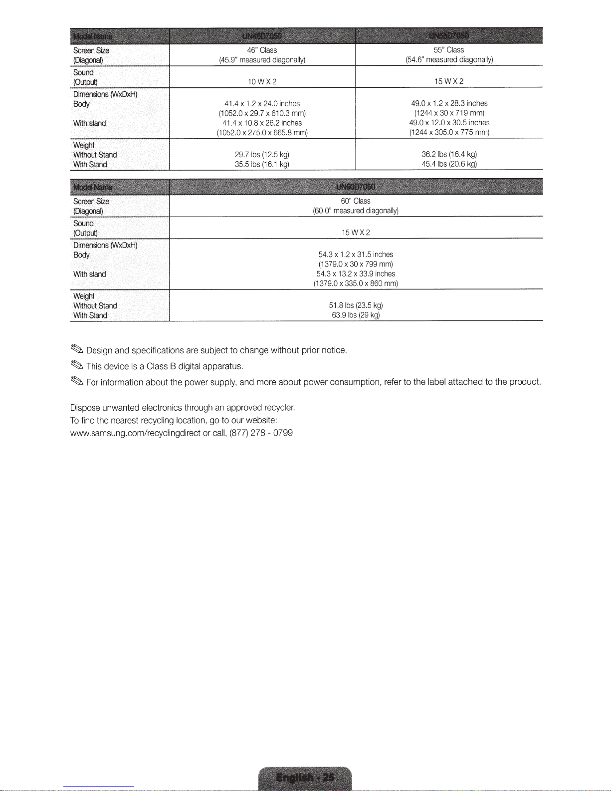
(45.9"
measured
agonally)
di
(54.6"
measured
diagonally}
Dimensions
Body
Withstand
Screen
{Diagona~
Sdund
(Output)
Dimensions
Body
With
Weight
Without
WithStand
~
~
~
(WxDxH)
Size
(WxDxH)
stand
.
Stand
and specifications
Design
device
This
information about
For
is
Class
a
(1052.0
(1
subject
are
digital apparatus.
B
supply,
power
the
10WX2
ches
in
24.0
x
1.2
x
41.4
29.7
x
x
10.8
x
41.4
275.0
x
052.0
29.71bs
lbs
35.5
change without prior notice.
to
more about power consumption,
and
610.3
x
26.2
x
(12.5
(16.1
inches
665.8
kg)
kg)
mm)
mm)
(60.0"
.3
54
(1379.0
54.3
(1379.0
51.8
63.9
Cl
60"
measured
15W
3
x
1.2
x
30
x
x
3.2
1
x
0
335.
x
(23.5
lbs
lbs (
ass
diagonally)
X2
inches
1.5
mm)
799
x
inch
33.9
860
x
kg)
kg)
29
es
mm)
refer
49.0
1244
(
49.0
(1244
to the
x
x
x
36.2
45.4
label
1.2
12.0
15WX2
28.3
x
719
x
30
x
30.5
x
x
305.0
(16.4
lbs
(20.6
bs
l
attached to
775
nches
i
mm)
inches
mm)
kg)
the
product.
ing
through
cat
lo
ion,
Dispose
find
To
unwanted
a
ne
the
st
re
electronics
ecycl
r
www.samsung.com/recyclingdirect
approved
an
to our website:
go
(877)
call,
or
cycle
re
278 - 0799
r.
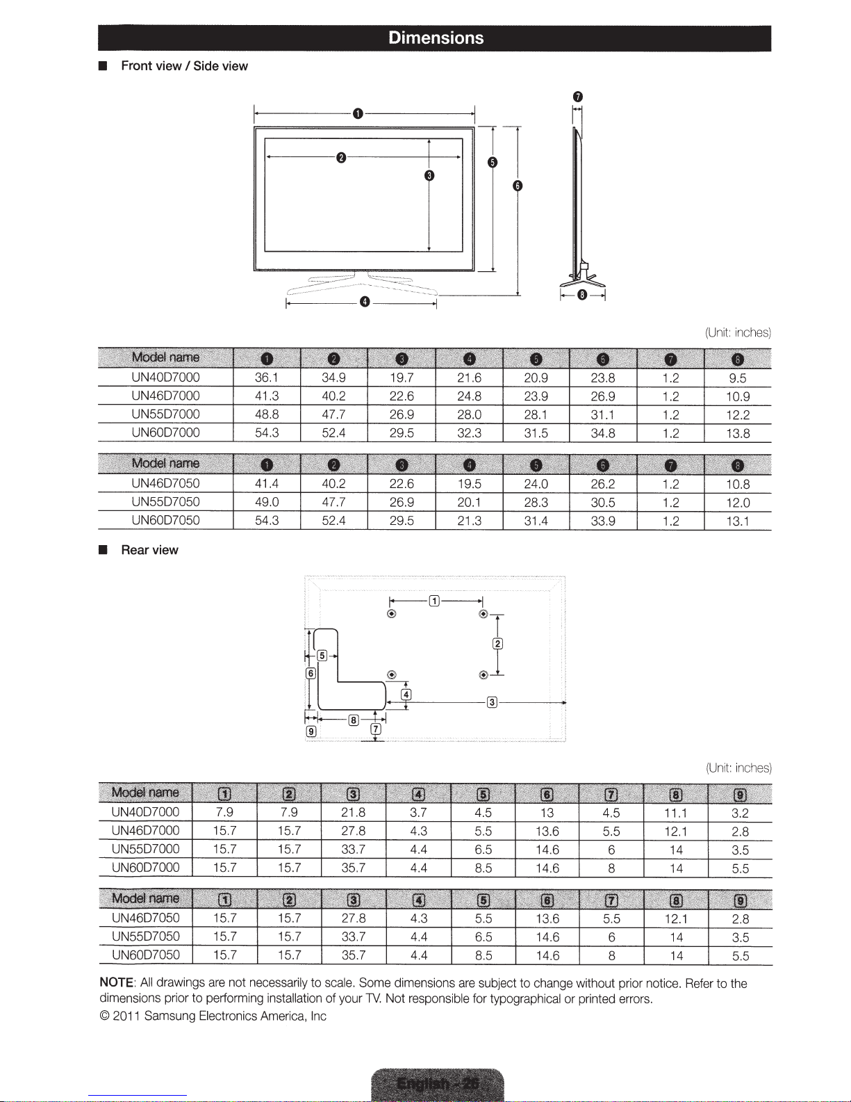
Dimensions
•
Front
view
I
Side
view
1-----
----
--
---
0---
e
--
--~
--
----+1
--
1
(Uni
t:
in
ches
)
•
Rearview
(U
ni
t:
inch
es
)
NOTE
:
All
dr
awings
are
not
necessa
dim
ens
ion
s prior to perform
©
20
11
Samsung
Ele
ctro
ing
in
s
tallation
ni
cs
Am
e
ri
rily
ca
to
sca
le.
Some d
of
your
,
In
c
TV
.
im
Not
e
nsions
are
responsible
subject to c
hange
for typographical
without p
or print
ed
ri
e
rrors.
or no
ti
ce
.
Refer
to the

Notice
FCC
Statement
Federal
This
FCC
This
Communication
equipment
Rules.
equipment
instructions,
not
occur
in a particular
can
be
determined
following
•
•
•
•
FCC
user's
This
not
cause
IC
This
Opera
any
measures:
Reorient
Increase
Connect
Consult
Caution:
authority to
device
cause
undesired
Statement
Class B digital
tion
interference,
has
been
These
limits
generates,
may
cause
by
or
relocate
the
separation
the
equipment
the
dealer
Any
changes
operate
complies
harmful
int
erference
operation.
apparatus
is
subject
to
including interferen
Commission
tested
and
found
are
designed
uses
harmful
installation.
turning
the
receiving
between
into
or
an
experienced
to
and
can
interference
If
this
the
equipment off
antenna.
the
an
outlet
or modifications not
this
equipment.
with Part
, a
15
of
nd
the FCC
(2)
complies
the
following two conditions:
ce that
Interference Statement
to comply
provide
radiate
to radio
equipment
equipment
on
a circuit
radio!TV
with
reasonable
radio
frequency
communications.
does
and
on, the
and
receiver.
different
technici
an
the
protection
cause
user
expressly approved
Rules.
Operation
this device
with
must
Canadian
may
cause
accept
ICES-003.
(1) this
undesired
device
limits
for a Class B digital
against harmful
energy
and,
However,
harmful
is
encouraged
from
that
to
for
help.
by
the
is
subject
any
interfer
may
not
operati
on
if
not
there
inte
rfere
to try to correct
which
party
responsible
to
the following
ence
received,
cause
of t
he
installed
is
nce
to
the
receiver
int
erference,
device.
device,
interferen
and
no
guarantee
radio
or
is
for
two cond
including int
pursuant
ce
in a
residential
used
in accordance wi
that
television
the int
erference
connected.
comp
liance
itions:
erference that
and
(2)
this
to
Part
15
of
the
installation
th
the
interference
reception,
could
(1)
This
which
by
one
void the
device
wil
of
may
may
device must accept
.
l
the
Cet
appareil
This device
Conformite
Cet
appareil
eta
Ia
norme
Son
foncti
brouillage
pouvant
causer
numerique
and
its
antenna(s)
aux
normes
et
ses
accessoires
NMB-003
onnement
est
prejudiciable,
un
fonctionn
de
Ia
FCC
classe
sujet
et
(2)
ement
classe B est
must not
Part 15
sont
be co-located or o
Class
conformes
B d'lndustrie
aux
deux
conditions
cet
appa
reil
indesirab
conforme a
B
aux
normes
Canada
suivantes:(
et
ses
accessoi
le.
Ia
sur
norme
peration
FCC
les
appareils
1)
res
doivent
NMB-003
Part
du
in
conjunction
15
Class B de
numeriq
Cet
appare
il
et
accepter toutes les
Canada.
with
ues
.
ses
accessoires
any
Ia
Federal
other
antenna
Communications
ne
int
erferences
doi
vent
or
transmitter.
pas
re<;:ues,
Commission
provoquer de
y compris celles
Contact
If
Comuniquese
Si
atenci6n al
Comment
Si
Samsung.
SAMSUNG WORLDWIDE
Samsung
comments relating
you have any questions
con
desea formular alguna pregunta o comentario en relaci6n con
cliente
contacter
vous avez des suggestions ou des questions concernant
or
SAMSUNG WORLD WIDE
SAMSUNG.
de
le
Samsung
dans
to
monde
products. please contact the
productos de Samsung,
los
les
produits
Samsung, veuillez contacter le Service
SAMSUNG
comuniquese con el centro
customer care center.
de
Consommateurs
CANADA
U.S.A 1-800-SAMSUNG
1-800-SAMSUNG
(726-7864) www.samsung.com
(726-7864) www.samsung.com
Samsung
55
Canada
Samsung
Road Ridgefield Park, NJ
Electronics Canada Inc., Customer
Standish
Court Mississauga, Ontario
Electronics America,
85
Inc.
07660-2112
Service
4B2
LSR
Challenger
Samsung Electronics Co., Ltd. All
2011
©
rights reserved.
1111111111111111111111111111111111111111111
BN68-03435E-
OO
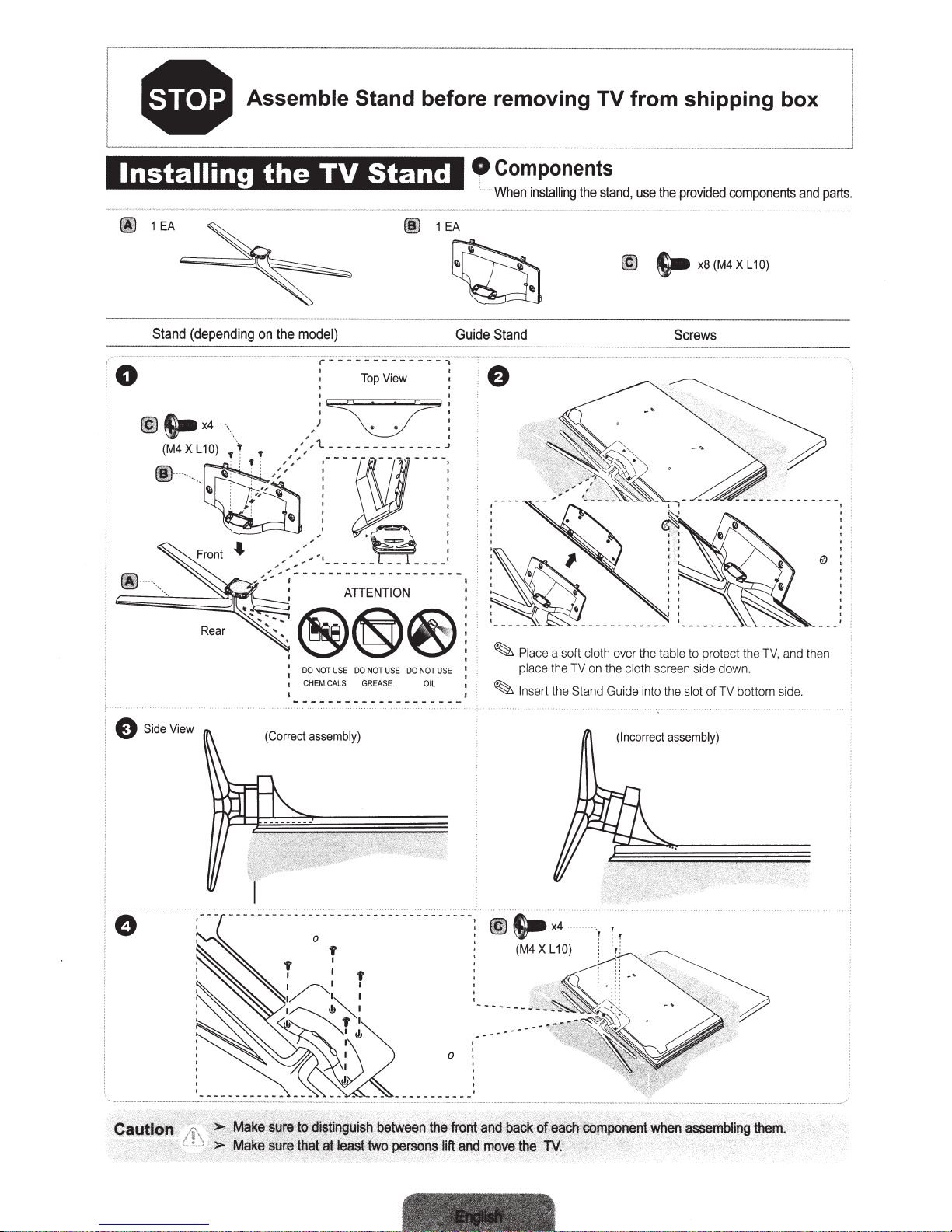
I
i
• Assemble Stand
-------
before removing TV
-
from
----
-
--
shipping
-
·
··
-
--
~
box
:
Installing
~
1EA
Stand
(depending
0
~
fiill
~
l.-x4
(M4
.....
X L 1
_
'
•.
~
0)
·-
·\._
;r
• •
the
on
,
T •
''
1
0
EA
Guide
I
TV
Stand
fl)
the
model}
Top
View
I I
)c::z:Tl
' I
,
'~-------------J
,
' '
,
,
,
,,
Components
' ·
When
installing
Stand
the
stand,
@)
use
the
s..
provided
x8(M4XL10)
Screws
____
components
and
j
parts.
(Correct
assembly)
~
~
Place
a soft cloth
place the
In
sert
the
TV
on
Stand
over the
the
cloth
Guide
(Incorrect
table
to protect the TV, and
scr
ee
n s
id
in
to the
slot
assembly)
e down.
of TV bottom side.
th
en
'
§tii~fi
.
betw~
&
le
~s.tt
wo
perso
tf.l~
'
ftoijtarrd
ijs·
litt
arid
back
:
mo~
the
.
BN68-03389A-05
1111111111111111111111111111111111111111111
BN68-03389A-05
 Loading...