

Page 1
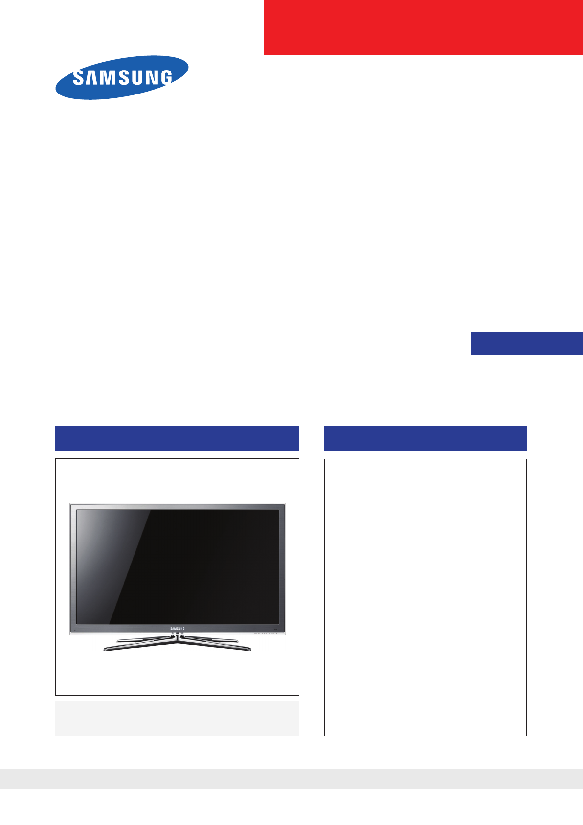
LED-TV
Chassis : N81B
Model : UN40C8000XM
UN46C8000XM
UN55C8000XM
UN65C8000XM
Manual
SERVICE
TFT-LED TV Contents
1. Precautions
2. Product specications
3. Disassembly and Reassembly
4. Troubleshooting
5. Exploded View & Part List
6. Wiring Diagram
UN40C8000XM / UN46C8000XM
UN55C8000XM / UN65C8000XM
Refer to the service manual in the GSPN (see the rear cover) for the more information.
Page 2

Contents
1. Precautions .............................................................................................................. 1-1
1-1. Safety Precautions ......................................................................................................... 1-1
1-2. Servicing Precautions .....................................................................................................1-2
1-3. Electrostatically Sensitive Devices (ESD) Precautions .................................................. 1-2
1-4. Installation Precautions .................................................................................................. 1-3
2. Product specications ............................................................................................ 2-1
2-1. Feature & Specications ................................................................................................. 2-1
2-2. Spec Comparison to the Old Models .............................................................................. 2-5
2-3. Detail Factory Option ...................................................................................................... 2-6
2-4. Channel Table ................................................................................................................. 2-7
2-5. New Functional Explanation ........................................................................................... 2-9
2-6. Accessories .................................................................................................................. 2-24
3. Disassembly and Reassembly ............................................................................... 3-1
3-1. Disassembly and Reassembly ....................................................................................... 3-1
4. Troubleshooting ...................................................................................................... 4-1
4-1. Troubleshooting .............................................................................................................. 4-1
4-2. Alignments and Adjustments ........................................................................................ 4-32
4-3. Factory Mode Adjustments ........................................................................................... 4-33
4-4. White Balance - Calibration .......................................................................................... 4-49
4-5. Servicing Information .................................................................................................... 4-51
5. Exploded View & Part List ...................................................................................... 5-1
5-1. Exploded View ................................................................................................................ 5-1
5-2. Parts List ......................................................................................................................... 5-2
6. Wiring Diagram ........................................................................................................ 6-1
6-1. Wiring Diagram ............................................................................................................... 6-1
6-2. Connector ....................................................................................................................... 6-2
6-3. Connector Functions ...................................................................................................... 6-4
6-4. Cables ............................................................................................................................ 6-4
Page 3
GSPN (Global Service Partner Network)
Area Web Site
North America http://service.samsungportal.com
Latin America http://latin.samsungportal.com
CIS http://cis.samsungportal.com
Europe http://europe.samsungportal.com
China http://china.samsungportal.com
Asia http://asia.samsungportal.com
Mideast & Africa http://mea.samsungportal.com
This Service Manual is a property of Samsung Electronics Co.,Ltd.
Any unauthorized use of Manual can be punished under applicable
International and/or domestic law.
© 2010 Samsung Electronics Co.,Ltd.
All rights reserved.
Printed in Korea
P/N: BN82-00978A-00
Page 4
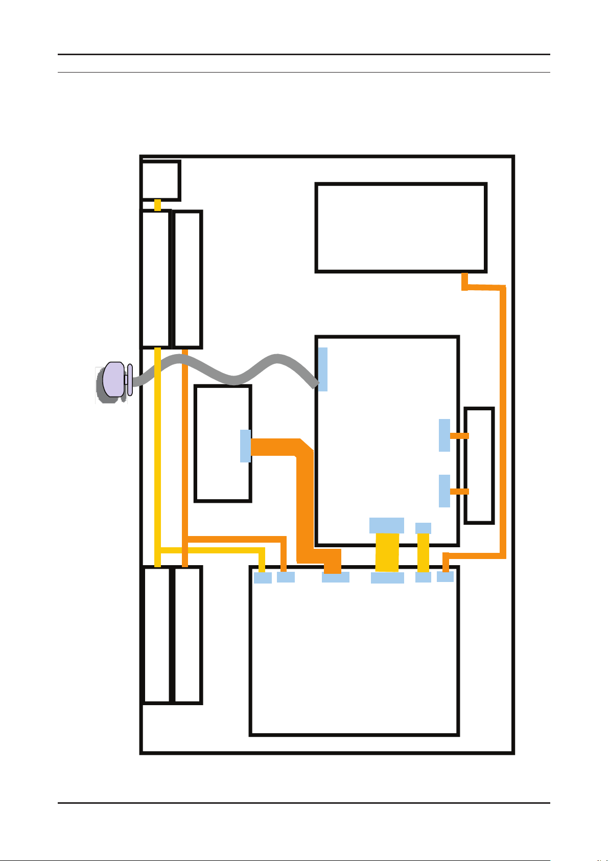
6. Wiring Diagram
T-CON
SMPS
Woofer
Speaker
Function
Main Board
CN1701
CN2101
CNL801
CNM802
IR
Panel
CN302
CN601
CN301W
CN802S
POWER CORD
Speaker
CN201
Emitter
CON1
CNL803
CNL802
6-1. Wiring Diagram
46" / 55" / 65"
6. Wiring Diagram
6-1
Page 5
6-2
6. Wiring Diagram
6-2. Connector
CN2101(to T-CON)
GND
1
GND
2
SW_PVCC
3
FRC_RESET
4
SDA
5
SCL
6
LVDS opt
7
H-Sync Out
8
Panel_WP
9
T_Con Check
10
NC
11
NC
12
GND
13
RE[4]+
14
RE[4]-
15
RE[3]+
16
RE[3]-
17
GND
18
RECLK+
19
RECLK-
20
GND
21
RE[2]+
22
RE[2]-
23
RE[1]+
24
RE[1]-
25
RE[0]+
26
27
28
29
30
31
32
33
34
35
36
37
38
39
40
41
42
43
44
45
46
47
48
49
50
51
RE[0]GND
RO[4]+
RO[4]RO[3]+
RO[3]GND
ROCLK+
ROCLKGND
RO[2]+
RO[2]RO[1]+
RO[1]RO[0]+
RO[0]GND
GND
GND
NC
Panel_VCC
Panel_VCC
Panel_VCC
Panel_VCC
Panel_VCC
CN302(to Speaker)
1
R+
2
R-
3
L+
4
L-
CN301W(to Woofer)
1
SW+
2
SW-
3
SW+
4
SW-
CN601
1
IR
2
GND
3
A3.3V
4
LED_INDICAT
5
BUZZER
6
KEY1
7
8
9
10
11
12
KEKY2
NCL
A5V
NC
LED_CTRL
B5V
CN502(to HDMI1)
HDMI1_RX2+
1
DGND
2
HDMI1_RX2-
3
HDMI1_RX1+
4
DGND
5
HDMI1_RX1-
6
HDMI1_RX0+
7
DGND
8
HDMI1_RX0-
9
HDMI1_RXCLK+
10
11
DGND
12
HDMI1_RXCLK-
13
HDMI_CEC
14
DGND
15
HDMI1_DDC_SCL
16
HDMI1_DDC_SDA
17
DGND
18
HDMI1_5V
19
HDMI1_HPD
CN401(to PC_IN)
PC_RED
1
PC_GREEN
2
PC_BLUE
3
DGND
4
DGND
5
DGND
6
DGND
7
DGND
8
9
PC_5V
10
PC_IDENT
11
DGND
12
SDA_DOWN
13
PC_H_SYNC
14
PC_V_SYNC
15
SCL_DOWN
CN1403(to USB1)
1
USB0_VCC
2
USB0_DM
3
USB0_DP
4
DGND
CN1401(to USB2)
1
USB1_VCC
2
USB1_DM
3
USB1_DP
4
DGND
Page 6
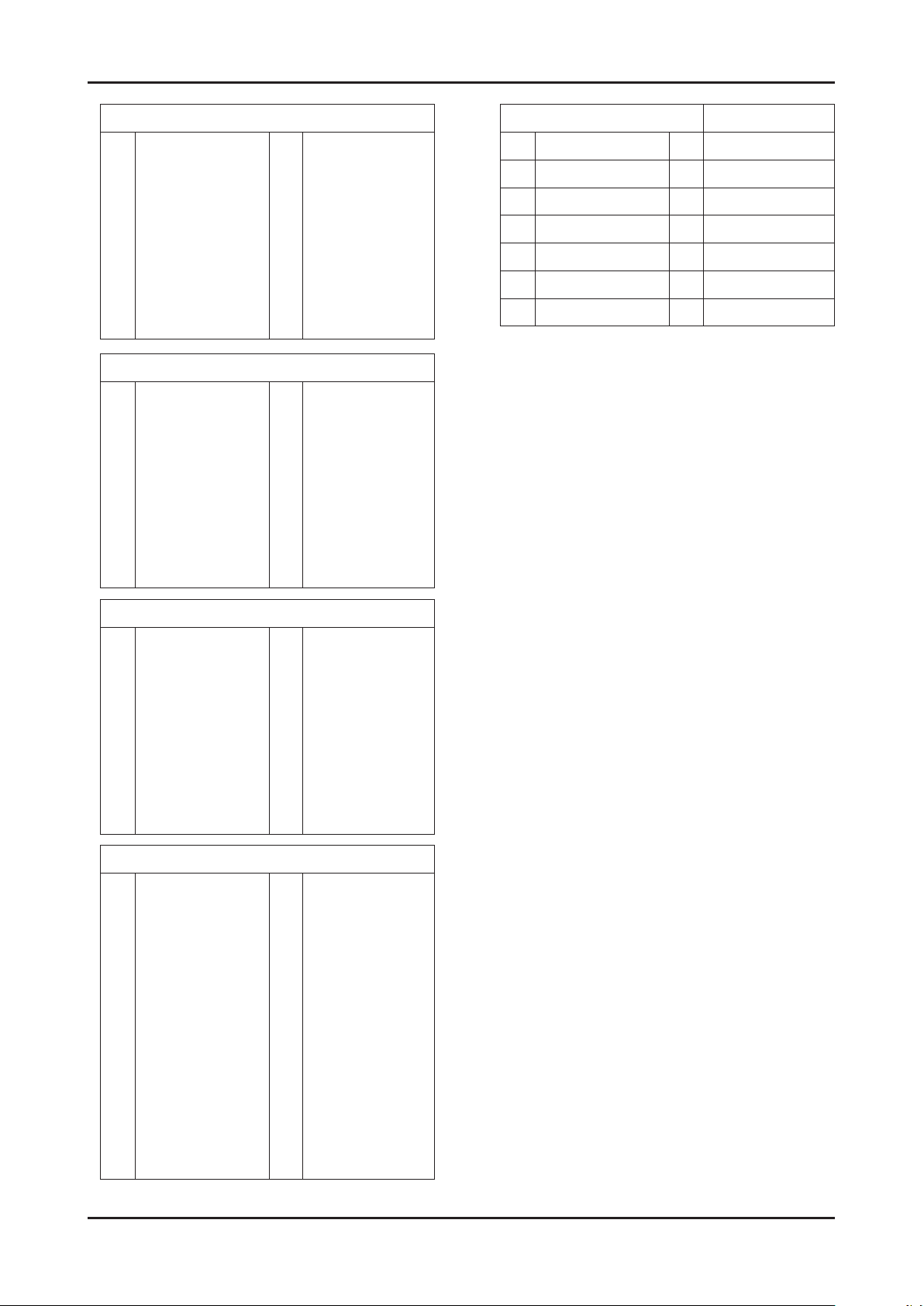
6-3
6. Wiring Diagram
CN503(to HDMI2)
HDMI2_RX2+
1
DGND
2
HDMI2_RX2-
3
HDMI2_RX1+
4
DGND
5
HDMI2_RX1-
6
HDMI2_RX0+
7
DGND
8
HDMI2_RX0-
9
HDMI2_RXCLK+
10
CN504(to HDMI3)
HDMI3_RX2+
1
DGND
2
HDMI3_RX2-
3
HDMI3_RX1+
4
DGND
5
HDMI3_RX1-
6
HDMI3_RX0+
7
DGND
8
HDMI3_RX0-
9
HDMI3_RXCLK+
10
DGND
11
HDMI2_RXCLK-
12
HDMI_CEC
13
DGND
14
HDMI2_DDC_SCL
15
HDMI2_DDC_SDA
16
DGND
17
HDMI2_5V
18
HDMI2_HPD
19
DGND
11
HDMI3_RXCLK-
12
HDMI_CEC
13
DGND
14
HDMI3_DDC_SCL
15
HDMI3_DDC_SDA
16
DGND
17
HDMI3_5V
18
HDMI3_HPD
19
CN1701
1 SSTT_LEFT 8 DGND
2 SDATA_LEFT 9 DGND
3 VSYNC_IN_LEFT 10 NC
4 DGND 11 NC
5 SEN0_LEFT 12 SCL_D
6 SCLK_LEFT 13 SDA_D
7 SEN1_LEFT 14 SW_RESET_LEFT
CN501(to HDMI4)
HDMI4_RX2+
1
DGND
2
HDMI4_RX2-
3
HDMI4_RX1+
4
DGND
5
HDMI4_RX1-
6
HDMI4_RX0+
7
DGND
8
HDMI4_RX0-
9
HDMI4_RXCLK+
10
CN201(to CNM802)
NC
1
NC
2
DET_5V
3
NC
4
PWM
5
DGND
6
B5V
7
NC
8
B13V
9
B13V
10
B13V
11
DGND
12
DGND
13
DGND
14
B5V
15
DGND
11
HDMI4_RXCLK-
12
HDMI_CEC
13
DGND
14
HDMI4_DDC_SCL
15
HDMI4_DDC_SDA
16
DGND
17
HDMI4_5V
18
HDMI4_HPD
19
B5V
16
B5V
17
B5V
18
DGND
19
DGND
20
DGND
21
DGND
22
B12VS
23
B12VS
24
DGND
25
DGND
26
A5V
27
DGND
28
A5V
29
FRC_M_HSYNC
30
Page 7
6. Wiring Diagram
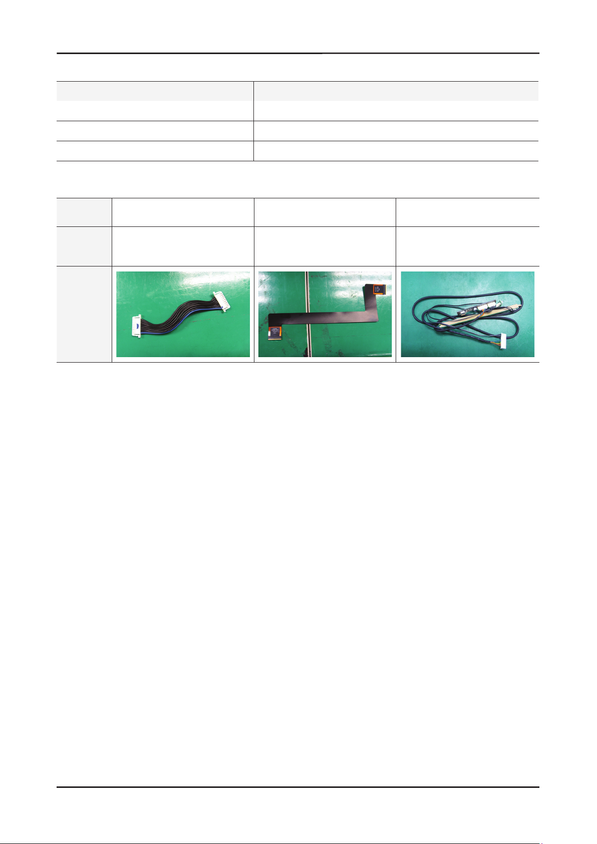
6-3. Connector Functions
Connector Functions
CNM801 CN201
CN2101 T-CON
CNL803 CN1701
Supply power from SMPS to Main Board.
The LVDS signal transfered from Main Board to Panel.
Main Board controls LED Driver for Local Dimming.
6-4. Cables
Use Main-SMPS Main-Tcon Function Assy
Code
Photo
40",46",55" : BN39-01291A
65" : BN39-01375A
46" : BN96-12723Q
55" : BN96-12723R
65" : BN96-14108E
46" : BN96-14056C
55" : BN96-14056D
65" : BN96-15474G
6-4
Page 8
4. Troubleshooting
4. Troubleshooting
4-1. Troubleshooting
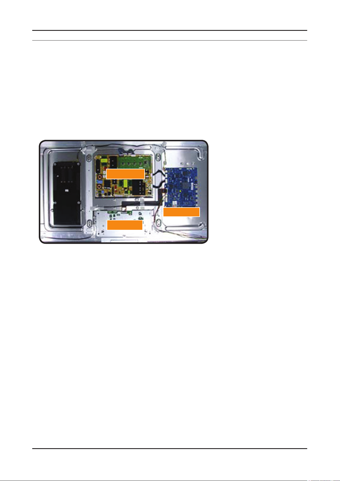
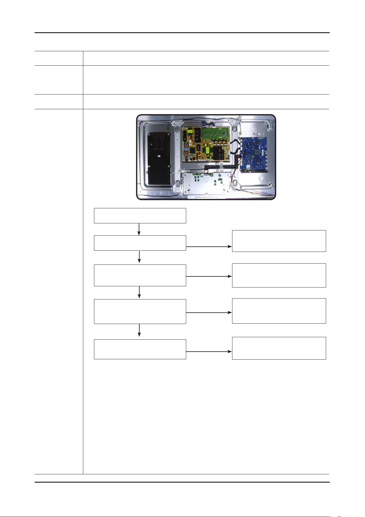
Check the various cable connections rst. 1.
• Check to see if there is a burnt or damaged cable.
• Check to see if there is a disconnected or loose cable connection.
• Check to see if the cables are connected according to the connection diagram.
Check the power input to the Main Board.2.
Check the internal patterns from the SVC option. 3.
FBE : Factory mode(INFO - MENU - MUTE POWER ON when TV is "standby on") -> SVC -> Test Pattern -> FBE
Pattern Sel "FBE pattern is created by Main IC(Valencia)
Case1: FBE pattern is ok , then change the T-con Board.
Case2: FBE pattern is NG , change the main Board.
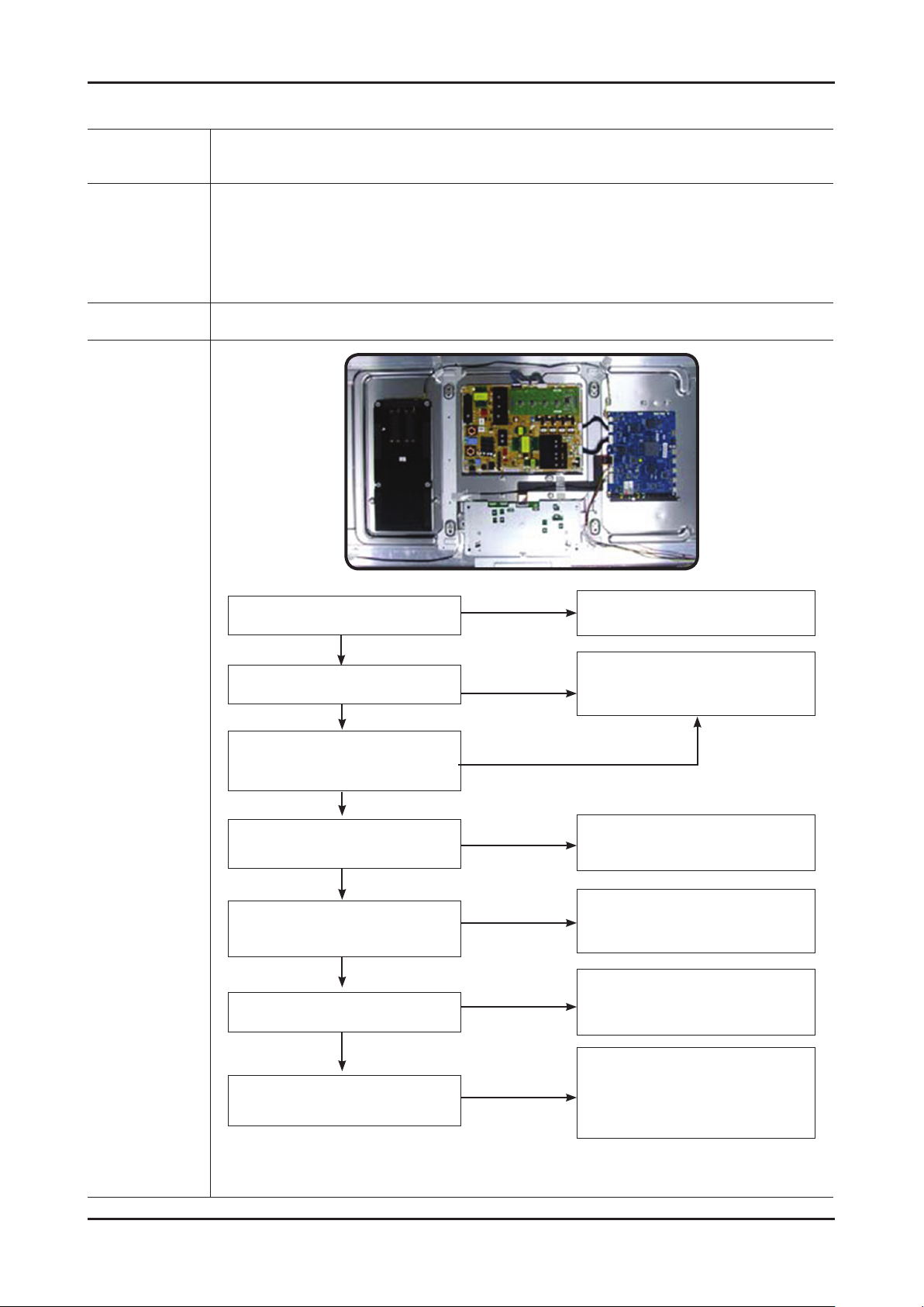
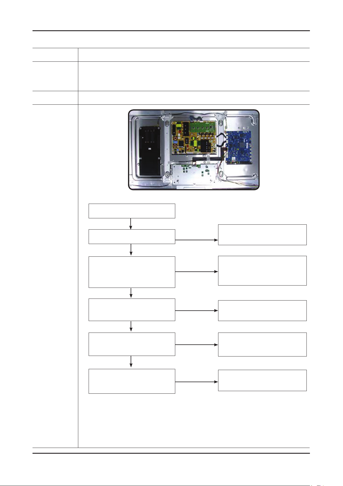
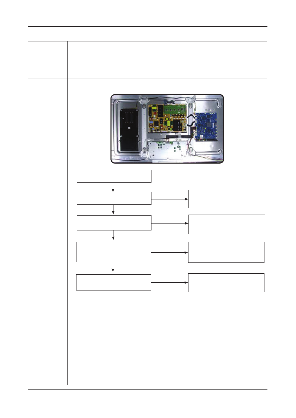
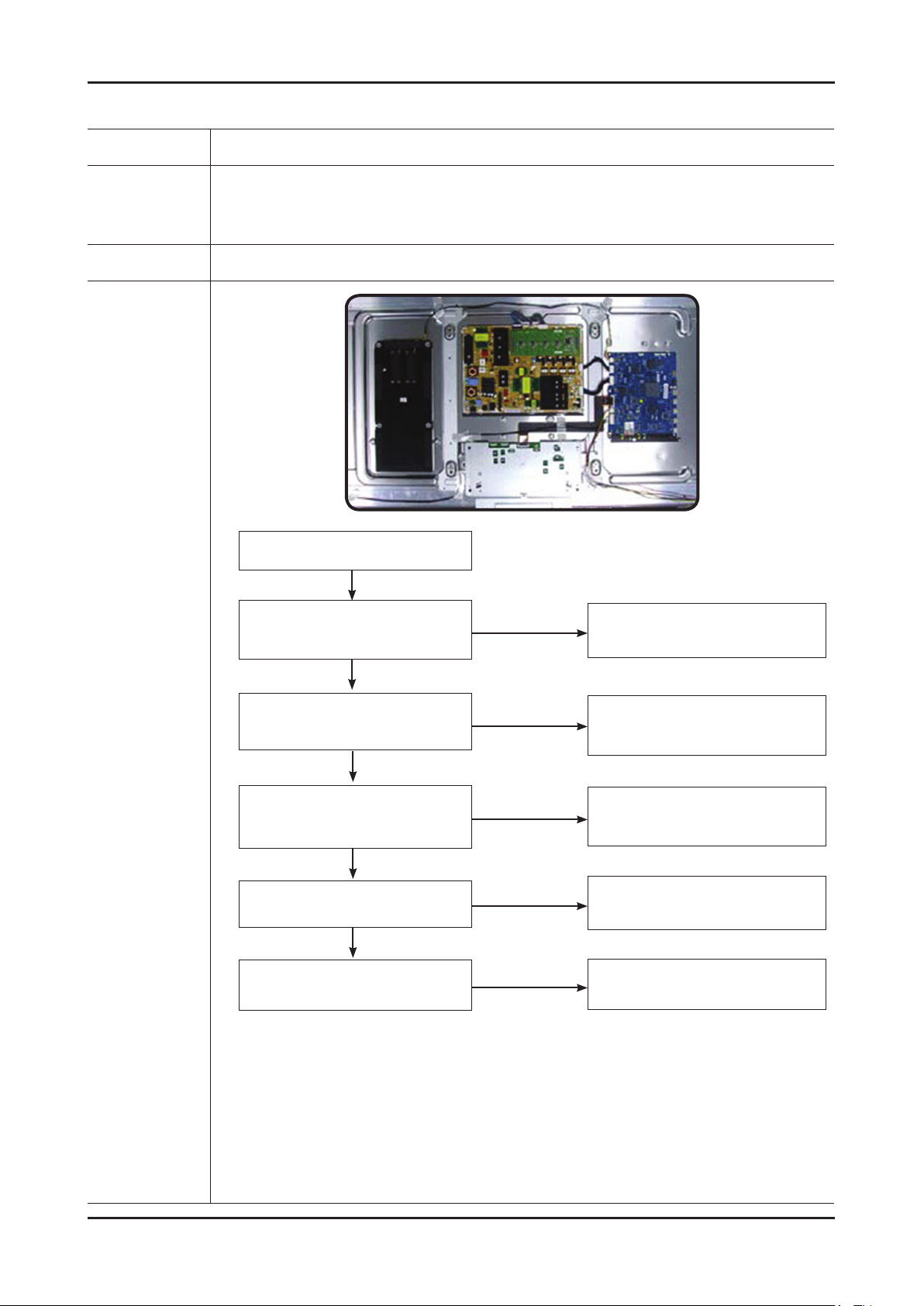
SMPS BOARD
T-CON
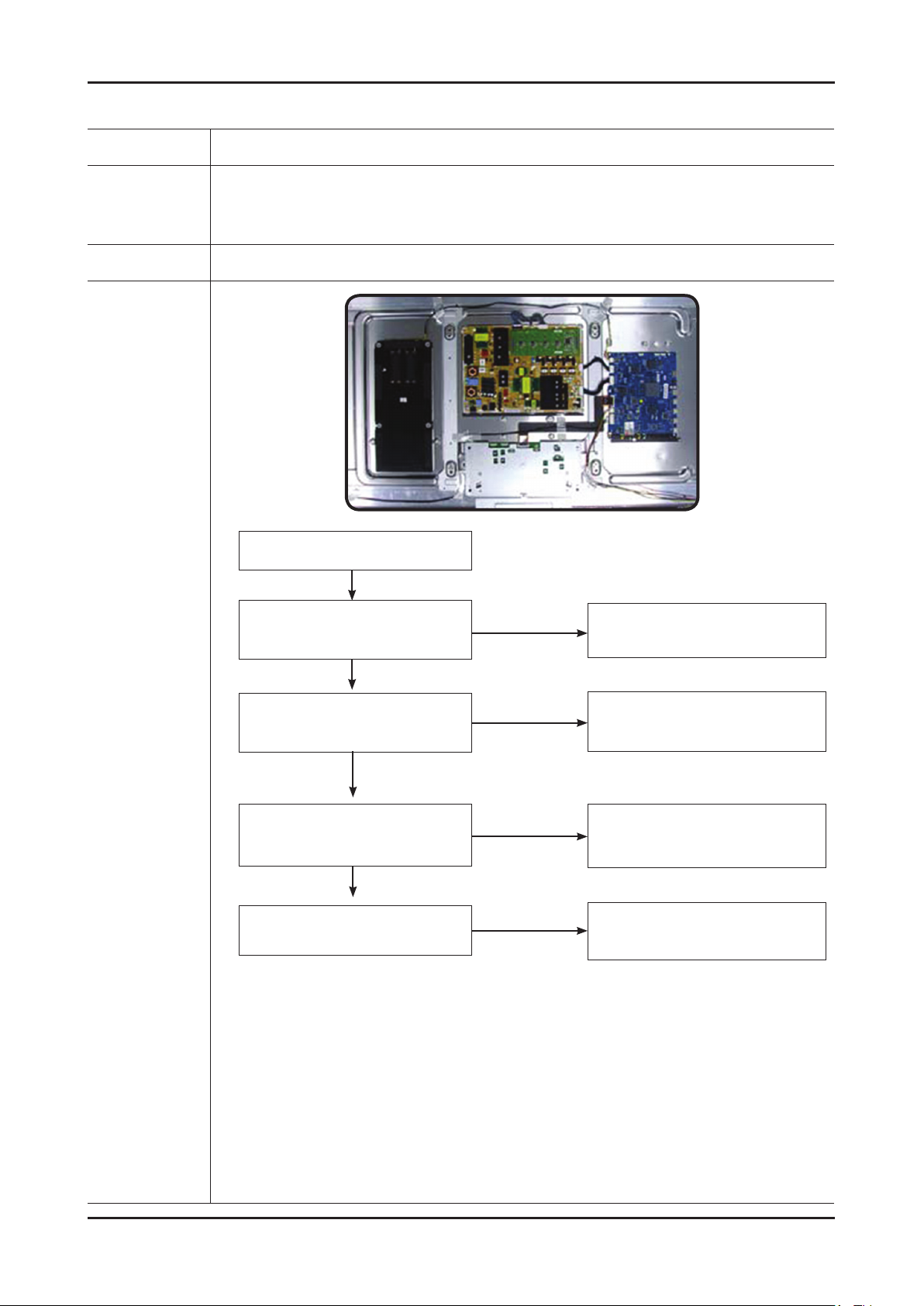
MAIN BOARD
4-1
Page 9
4-2
4. Troubleshooting
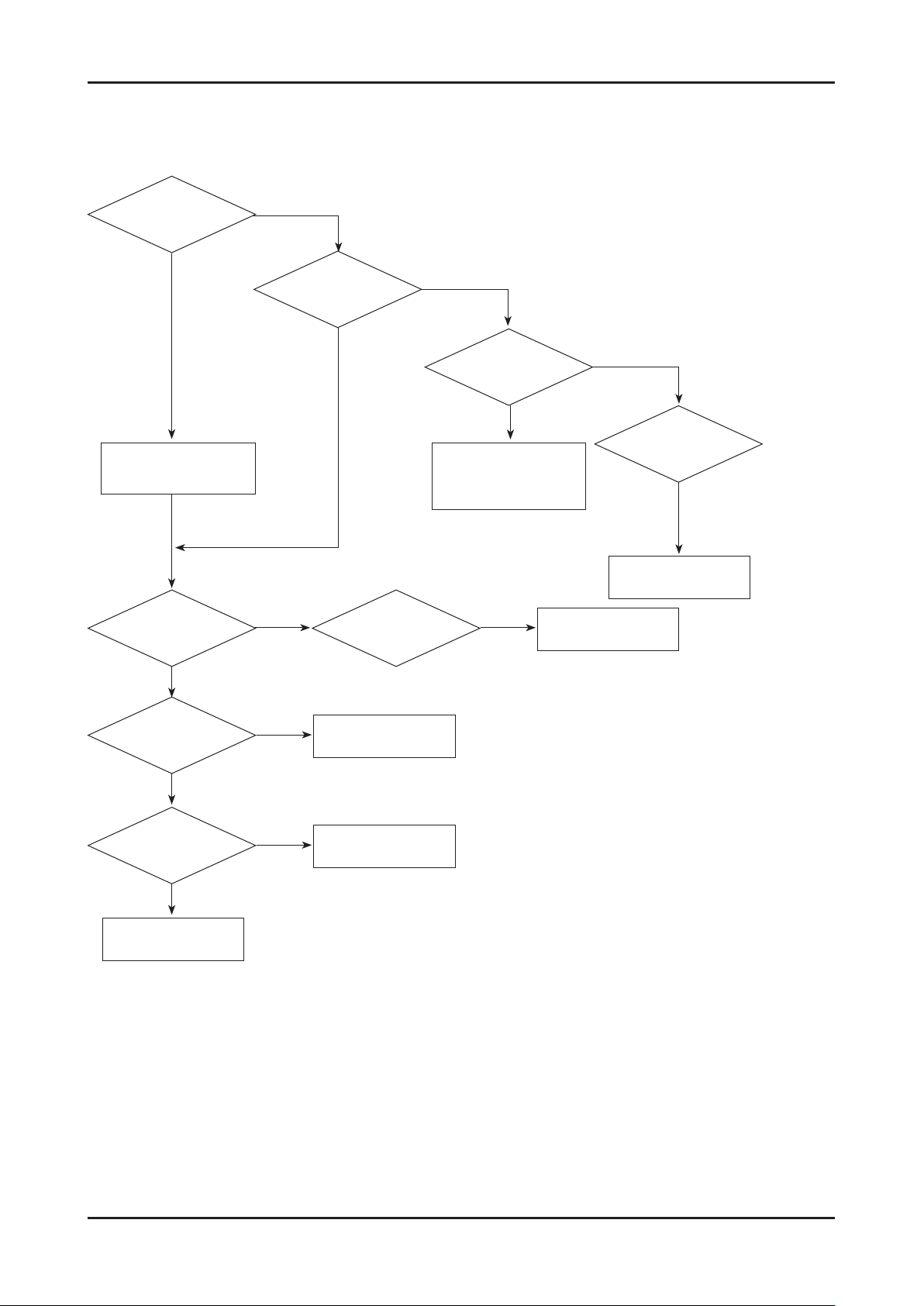
Simple ow chart of malfunction
Does the TV turn on?
No
Check the Power Cord
Yes
is any sound of TV
when RF signal
connected?
No
Yes
Can you see anything
on the screen?
Yes
Yes
No
Check LVDS cable connected
Check LVDS
cable connected.
If necessary replace the
T-con board.
Can you see
OSD menu running on
the screen?
No
to Main Board.
If necessary,
replace the Main Board
No
Change the main board.
Yes
Can you see Digital
Channel broadcast ?
No
Replace the Main Board
A5V appear at
the pin 4 of CN1001?
Yes
B13V appear at the
pin 13,15,17 of
CN1001?
Yes
Please, contact Tech
support
No
No
Check 18p cable.
If necessary, replace the
SMPS board.
Change the main board.
Page 10
4-3
4. Troubleshooting
Page 11
4-4
4. Troubleshooting
Troubleshooting about new functions
Problem
AllShare (General)•
I see no device connected to AllShare.
I tried to play a video from my cell phone
using the Connected Home function on the
Samsung TV but the video would not display
on the TV.
A video that can be played on my cell phone
cannot be played on my TV.
I cannot resume playback of a video using
Connected Home.
When I play a video through Connected
Home, I get intermittent picture loss.
Possible Solution
To use a device connected to AllShare, the device must be connected to PC •
Share Manager which is the DLNA server for MediaPlay and to a cell phone that
has the Connected Home or Screen Share function which are found on Samsung
Smartphones.
Check that the PC Share Manager is enabled, the Samsung TV is set to allow •
connections and the ScreenShare function on the connected cell phone is enabled.
To use the cell phone’s Connected Home function, check that the shared folder is •
set and the Share mode is ‘On.’
When a video is transmitted from Connected Home to a TV for the rst time, the •
settings screen that allows transfer to a TV is displayed.
Check that the transfer was not set to be rejected on this settings screen. If you •
have set the cell phone to ‘Blocked’ in the ‘Media’ options of the AllShare settings,
please change the setting to ‘Unblocked’ and retry.
Please check the resolution and display format provided by MediaPlay of the TV.•
The resuming function is not supported for a video played on a cell phone.•
An 801.11b/g bandwidth network is used between a cell phone and a sharing •
device. There may be frequent buffering for HD quality videos, this also depends
on the condition of the wireless connection.
Please optimize your wireless Internet environment settings (avoid using wireless •
Internet or bluetooth altogether if possible) or lower the picture quality of the video.
AllShare (Notication)•
Can all devices with the DLNA function be
recognized through Notication?
Can I use all the services related to DLNA?
The notication screen that appears after
a device connects disappears within a few
seconds.
How can I access this connected device
again?
AllShare (ScreenShare Client)•
I cannot nd the RUIS on my cell phone.
Only Samsung software and devices with the DLNA server function can be •
recognized through Notication.
Presently, you can only use the services related to ScreenShare and MediaPlay. •
We will launch a new DLNA service in the future.
The DLNA Notication is only displayed when a device is rst connected to a TV. •
To access the device again, please use the AllShare menu.
Check that the cell phone is connected to the wireless sharing device correctly.1.
Check that the DTV is connected either using a network cable or wirelessly to the 2.
wireless sharing device correctly.
Conrm the IP address and subnet mask to ensure that the cell phone and DTV 3.
are connected to the same network.
Check that the RUIS on the cell phone is enabled.4.
If the RUIS on the cell phone is enabled, please disable it and then enable it again.5.
Page 12

4-5
4. Troubleshooting
Problem
AllShare (ScreenShare Server)•
I cannot nd the remote control service
provided by the ScreenShare Server from the
ScreenShare Client.
The DTV did not update after pressing
buttons on the remote control that uses the
remote control service on the ScreenShare
Client.
Possible Solution
Check that the ScreenShare Client device is correctly connected to the network of 1.
the sharing device that the DTV is connected to.
Run network test in the network setup menu and conrm that MAC Address, IP 2.
Address, Subnet, Gateway, DNS Server and Gateway Ping each shows a success
message.
In the network setup menu, check that the ScreenShare Client and ScreenShare 3.
Server are on the same subnet.
- You can conrm they are on the same subnet by checking the IP address,
subnet mask and gateway address of the TV and ScreenShare Client as follows:
- If the IP address of the DTV is 10.88.83.4 and the subnet mask is 255.255.255.0,
the rst six digits of the ScreenShare Client’s IP address must be the same
(10.88.83) as that of the DTV, and the subnet mask and gateway address must
be the same as the DTV.
- If the IP address of the DTV is 10.88.83.4 and the subnet mask is 255.255.0.0,
the rst four digits of the ScreenShare Client’s IP address must be the same
(10.88) as that of the DTV, and the subnet mask and gateway address must be
the same as the DTV.
Move from the Allshare screen to the Setup screen, and open the Setup menu to 4.
check if the ScreenShare Client is connected to the same ScreenShare Server as
the TV name shown in the Setup options.
Move from the Allshare screen to the Setup screen, and open ScreenShare to 5.
check that the device, ScreenShare Client, is found on the list at the right side and
is set to "Allowed."
Check that the TV is turned on. •
You cannot turn on the TV using the remote control service (on the ScreenShare)
when the TV is turned off.
Page 13
4-6
4. Troubleshooting
Problem
Network Setup•
How do I setup the network?
How do I check the network status?
In a network test over a wired connection,
the second items which include the IP
address, subnet, gateway and DNS server
fail.
In a network test over a wired connection,
the third item, gateway ping fails.
cannot connect to a wireless network.
Possible Solution
Click the [Menu] button and open [Setup] to select [Network]. •
Congure wired or wireless network settings.
For details, please refer to the IB.
Select [Menu] • [Setup] [Network] and run [Network Test] to see test results and
check the network status.
If the IP address, subnet mask and gateway address were typed in manually, •
check that valid values were entered.
(For example, 0.0.0.0 is not valid for an IP address, subnet mask or gateway
address.)
If the IP address the user entered in is invalid, change it to a valid IP address.
Check that the network cable is connected to the TV correctly.1.
If the TV is connected correctly, check whether the IP address is automatic or 2.
manual.
If the IP is automatic and connected to a sharing device, check the settings of the 3.
sharing device (AP) that is using a cable connection, or consult the corresponding
Internet service provider.
If the IP is manual, check if the IP address is entered correctly. 4.
(Here, the user should conrm if the manual IP address entered in is valid.)
If an encryption key must be entered in to connect to a sharing device, please 1.
check that the correct password set for the sharing device is entered.
Search surrounding sharing devices to see if there is a sharing device with the 2.
same SSID by selecting [Wireless Network Setup] and [Select Network].
If there is a sharing device with the same SSID, try to connect to this device.
If the IP address is set to automatic and you cannot connect to the sharing 3.
device using option 1 or 2, check the settings of the sharing device to see if the
DHCP server function on the sharing device is enabled. If disabled, activate the
function. (For details on how to set up the sharing device, see the manual for the
corresponding sharing device.)
If you still cannot connect to the sharing device after conrming options 1, 2 and 3, 4.
reset the sharing device and try again.
When using a wireless network, the user’s
wireless sharing device cannot connect to
the PBC (WPS).
The auto-conguring sharing device cannot
be connected to automatically through a
wireless dongle.
(Here, the user’s sharing device must
support auto-conguration.)
Although the TV is placed close to the AP
and the dongle is inserted into the TV, the
sharing device cannot be connected to using
auto-conguration.
Although the TV is placed close to the AP
and the dongle is inserted into the TV, the
sharing device cannot be connected to using
auto-conguration and a message that it is
connecting is displayed only.
Check if the sharing device of the user supports WPS. 1.
(Refer to the manual of the sharing device.)
Check if the user pressed the PBC button on the sharing device.2.
If there is another sharing device with WPS running nearby, a connection cannot 3.
be made. Please retry after 2 minutes.
Reset the sharing device and retry.4.
If the sharing device of the user is not Wi-Fi certied, it may not be able to connect 5.
using WPS.
Check if the sharing device of the user supports auto conguration. 1.
(For a list of sharing devices, refer to the IB or website.)
If the sharing device of the user supports auto conguration, place the sharing 2.
device as close as possible to the wireless dongle on the TV and try to re-establish
the connection. (Must be placed close to the TV to establish a connection.)
Select [Menu] • [Setup] [Network] and check if SWL is Off.
Check if the AP is not turned off during connection. •
If the AP is turned off, the TV will try to re-establish a connection for 2 minutes.
Page 14

4-7
4. Troubleshooting
Problem
Although the TV is placed close to the AP
and the dongle is inserted into the TV, the
sharing device cannot be connected to using
auto-conguration and a message that it is
connecting is displayed only.
In a network test over a wireless connection,
the second items which include the IP
address, subnet, gateway and DNS server
fail.
In a network test over a wireless connection,
the third item, gateway ping fails.
In a network test over a wireless connection,
the fourth item, Internet service test fails.
Possible Solution
If Samsung Wireless Link is On, a 5G-bandwidth wireless sharing device may not •
be found in a search (restriction).
If Samsung Wireless Link is Off or the product does not have the Samsung •
Wireless Link function, please retry searching to nd the sharing device. (May not
be found in a search depending on the settings of the wireless connection.)
If the IP address, subnet mask and gateway were typed in manually, check that •
valid values were entered. (For example, 0.0.0.0 is not valid for an IP address,
subnet mask or gateway address.)
If the IP address the user entered in is invalid, change it to a valid IP address.•
If the IP address is automatic and connected to a sharing device, check the 1.
settings of the sharing device (AP) that is using a cable connection, or consult the
corresponding Internet service provider.
If the IP address is manual, check that the IP address is entered in correctly. 2.
(Here, the user should conrm if the manual IP entered in is valid.)
Please consult the corresponding Internet service provider (an Internet network •
service provider the user has subscribed to such as KT).
Page 15
4-8
4. Troubleshooting
4-1-1. No Power
Symptom
Major
checkpoints
Caution Make sure to disconnect the power before working on the PD board.
The PD board relay does not work when connecting the power cord. The units appears to be dead. -
The PD relay does not work when connecting the power cord if the cables are improperly connected or the
Main Board or PD is not functioning. In this case, check the following:
Check the internal cable connection status inside the unit. Check the fuses of each part. Check the output voltage of PD. Replace the Main Board. -
Diagnostics
When power on, check the sound of
relay on?
Yes
Does proper Stand-By DC A5V appear
at the PIN 4 of CN1001?
Yes
Does proper Main DC B18VS, B5V,
B13V appear at the PIN 3, PIN 5,
PIN13 of CN
Does proper DC A3.3V appear at
the pin3 of IC1014?
Does proper DC B3.3V appear at
the pin8 of IC206, B9V appear at
3pin of IC1003?
Does proper Valencia core
3.3V,1.1V appear at C7001,C7022?
Yes
Yes
Yes
Yes
1001
?
No
No
No
No
No
No
check a connection power cable.
P/N : BN96-12845B
Change the Main Power assembly.
Change the IC1014 or the Main Assy.
Change the IC1008, IC1003 or
the Main Assy.
Change the IC1011, IC1005 or
the Main Assy.
A power is supplied to panel
appear at C9320?
No
Check a other function(No picture part).
Replace a LCD Panel.
Page 16
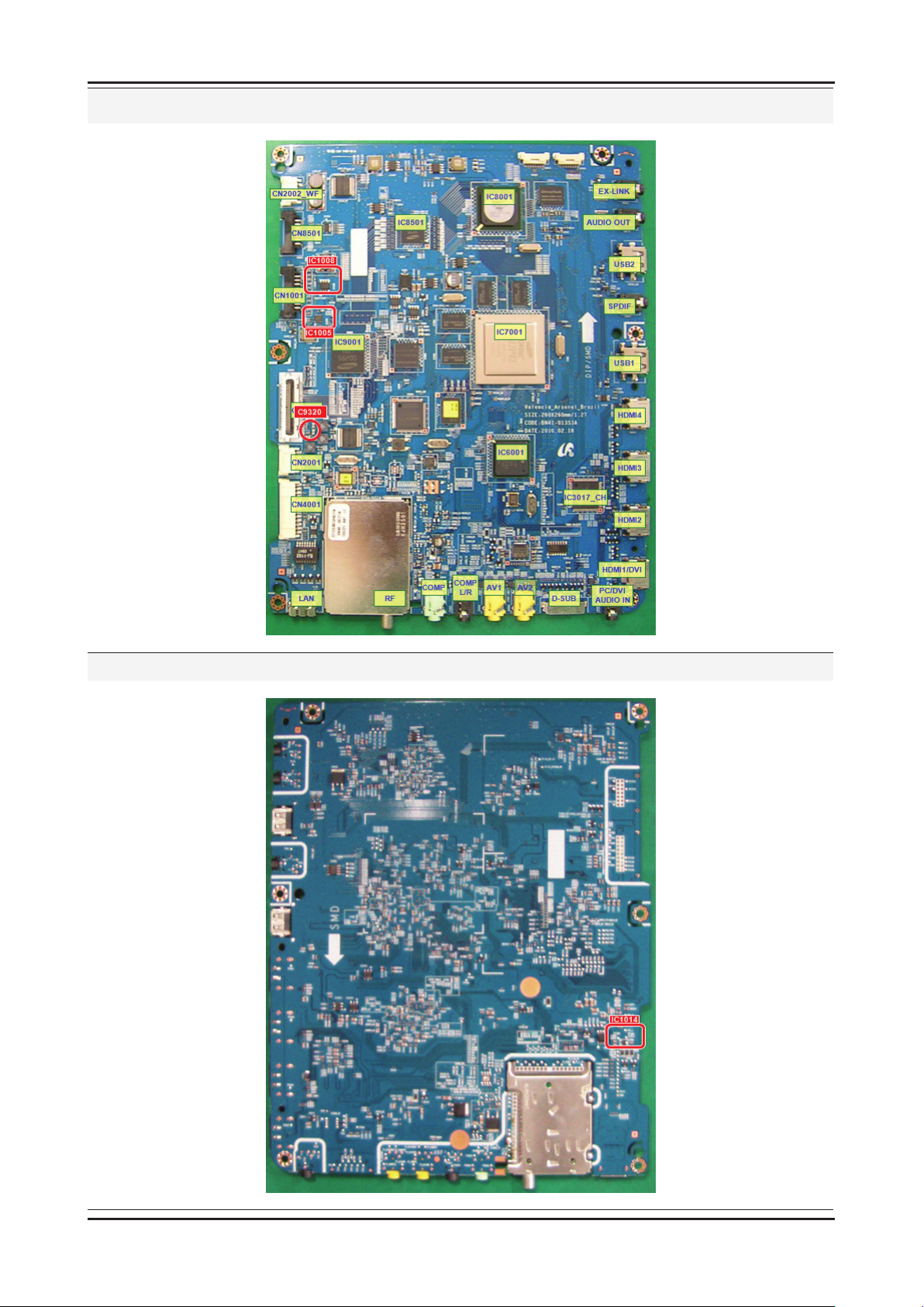
4-9
4. Troubleshooting
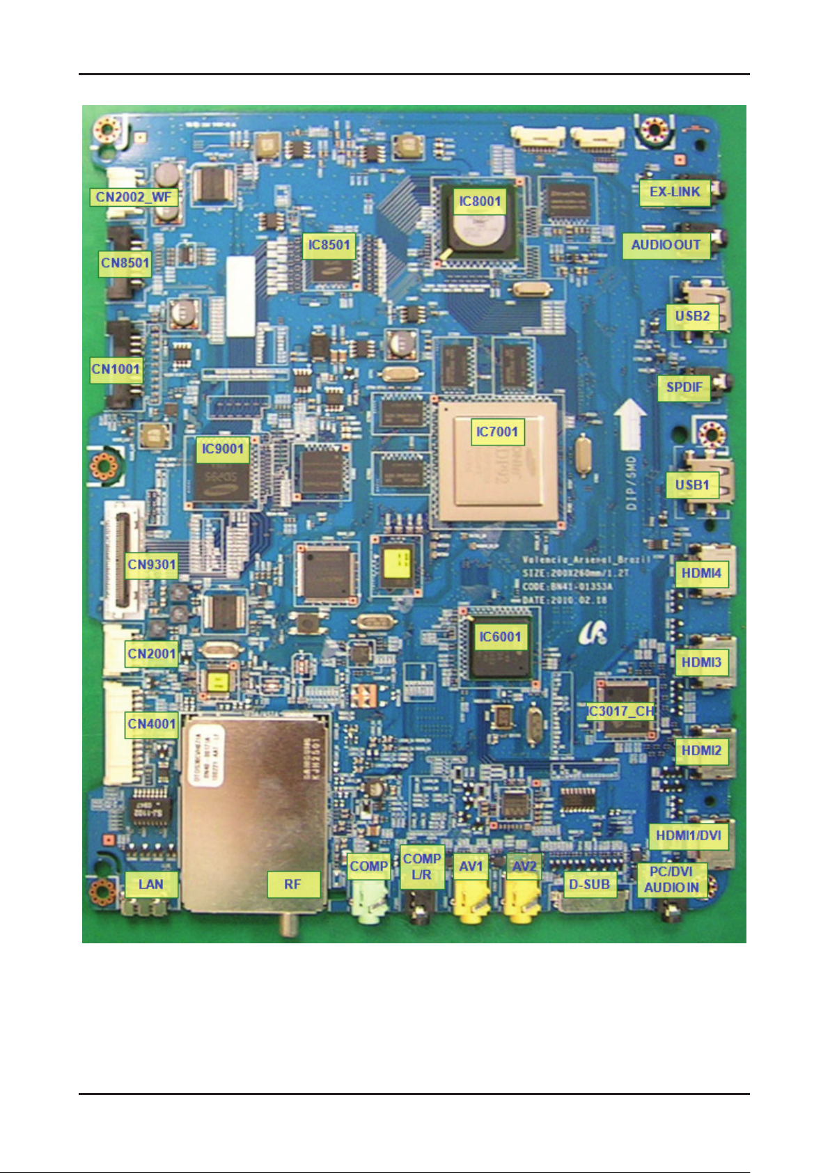
Location (Main) - TOP
Location (Main) - BOTTOM
Page 17
4-10
4. Troubleshooting
4-1-2. No Video (Analog PC signal)
Symptom Audio is normal but no picture is displayed on the screen. -
Major
checkpoints
Caution Make sure to disconnect the power before working on the PD board.
Check the PC source Check the IC7001(Valencia) This may happen when the LVDS cable connecting the Main Board and the Panel is disconnected. -
No video
Yes
Check the PC source and check the
connection of DSUB?
Yes
No
Input an analog PC signal.
Check the connected cable.
Diagnostics
Does the signal appear at pin 14, 16, 12,
1
2
6, 1(R,G,B,H,V) of CN3011?
Yes
Does the digital data appear at
output of IC6001?
Yes
Check the LVDS cable?
Replace the LCD panel?
No
No
No
Change the PC cable.
Change the main PCB assembly.
Change the IC6001 or
the main PCB assembly.
Please, contact Tech support.
Page 18
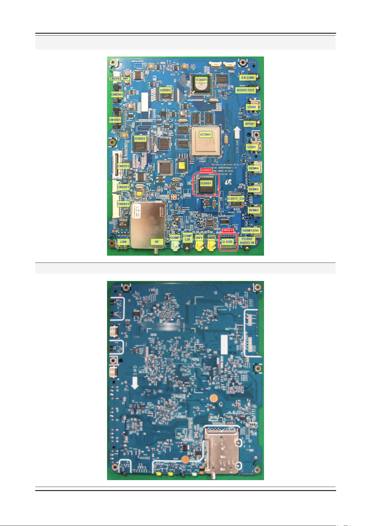
4-11
4. Troubleshooting
Location (Main) - TOP
Location (Main) - BOTTOM
Page 19
4-12
4. Troubleshooting
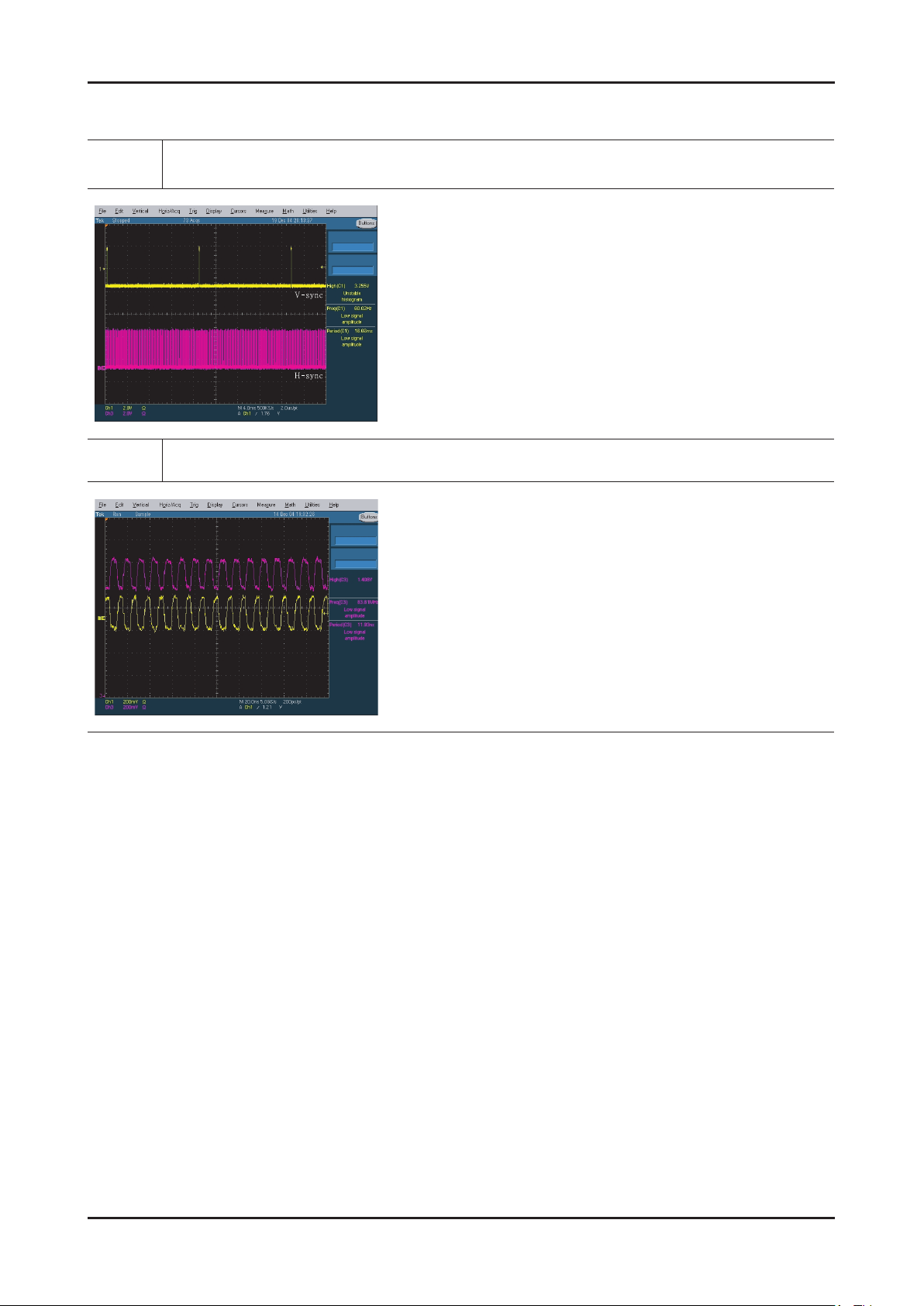
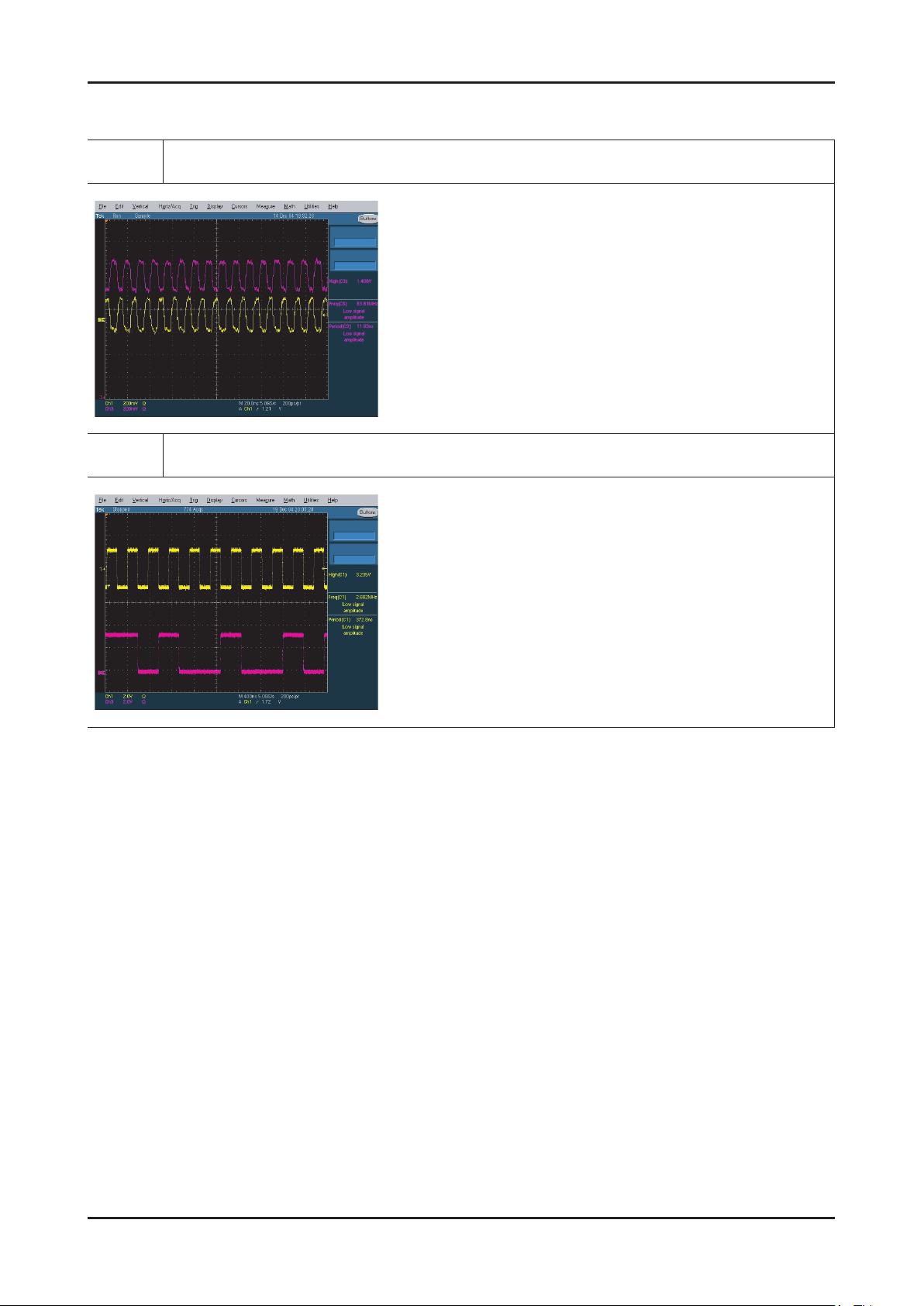
WAVEFORMS
1
2
PC Input (V-Sync, H-Sync)
LVDS Out (CLK + / -)
Page 20
4-13
4. Troubleshooting
4-1-3. No Video (HDMI - Digital Signal)
Symptom Audio is normal but no picture is displayed on the screen. -
Major
checkpoints
Caution Make sure to disconnect the power before working on the PD board.
Check the HDMI source -
Check the IC7001(Valencia) -
This may happen when the LVDS cable connecting the Main Board and the Panel is disconnected. -
No video
Yes
Check the HDMI source and
check the connection of HDMI cable?
Yes
No
Input an HDMI signal.
Check the connected cable.
Diagnostics
Does the signal appear at
IC3013_CH pin1~6, 99, 100(HDMI1),
3
pin8~15(HDMI2), pin17~24(HDMI3),
pin26~33(HDMI4)?
Yes
Does the digital data appear at output of
4
IC3013_CH pin80~87(HDMI output)?
Yes
5
Does the digital data appear at
pin 15~81 of CN9301?
Yes
Check the LVDS cable?
Check the T-con board?
Replace the LCD panel?
No
No
No
No
Change the HDMI cable.
Change the main PCB assembly.
Change the IC3013 or
the main PCB assembly.
Change the IC7001 or
the main PCB assembly.
Please, contact Tech support.
Page 21
4-14
4. Troubleshooting
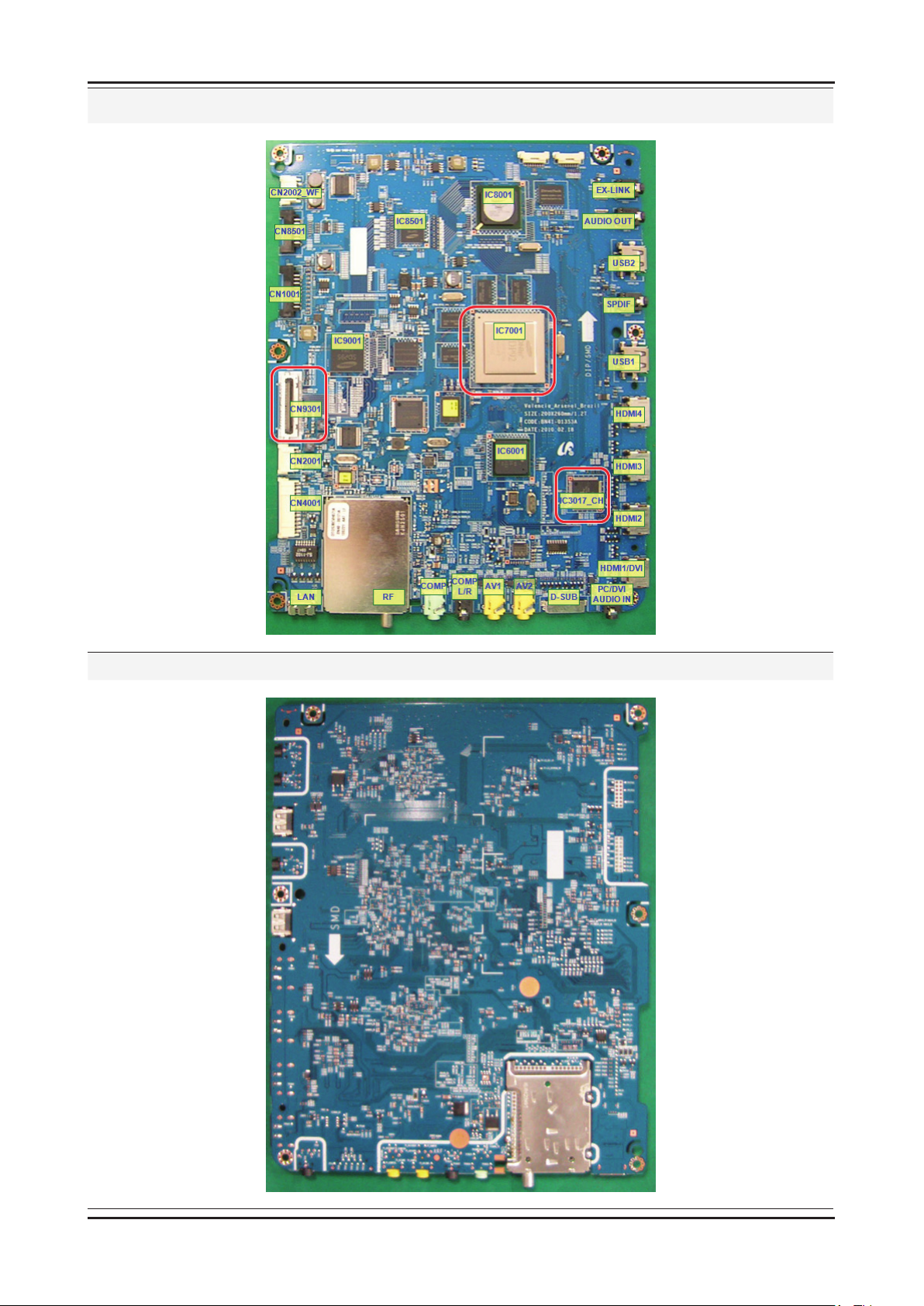
Location (Main) - TOP
Location (Main) - BOTTOM
Page 22
4-15
4. Troubleshooting
WAVEFORMS
3 4
5
HDMI Input (CLK + / -)
TS DATA Out (Clk, Data [0])
Page 23
4-16
4. Troubleshooting
4-1-4. No Video (Tuner_CVBS)
Symptom Audio is normal but no picture is displayed on the screen. -
Major
checkpoints
Caution Make sure to disconnect the power before working on the PD board.
Check the Tuner CVBS source -
Check the Valencia -
This may happen when the LVDS cable connecting the Main Board and the Panel is disconnected. -
No video
Yes
Check the RF source and
check the connection of RF cable?
Yes
No
Input the RF signal.
Check the connected cable.
Diagnostics
6
7
Does the signal appear at
pin11, 12 of TU5001_EA?
Yes
Does the digital data appear at
pin 15~81 of CN9301?
Yes
Check the LVDS cable?
Replace the LCD panel?
No
No
No
Change the TU5001_EA or
the main PCB assembly.
Change the IC7001 or
the main PCB assembly.
Please, contact Tech support.
Page 24
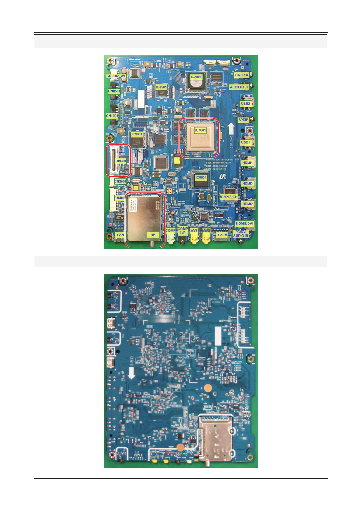
4-17
4. Troubleshooting
Location (Main) - TOP
Location (Main) - BOTTOM
Page 25
4-18
4. Troubleshooting
WAVEFORMS
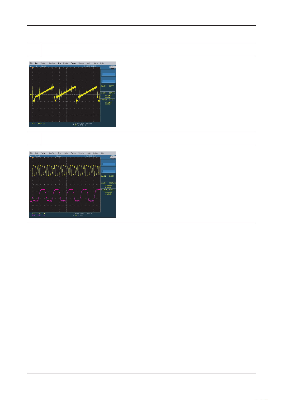
Tuner CVBS Out (Pattern: Grey Bar)
6
Eagle+ Out (Clk, H-Sync)
7
Page 26
4-19
4. Troubleshooting
4-1-5. No Video (Video CVBS)
Symptom Audio is normal but no picture is displayed on the screen. -
Major
checkpoints
Caution Make sure to disconnect the power before working on the PD board.
Check the Video CVBS source -
Check the Valencia -
This may happen when the LVDS cable connecting the Main Board and the Panel is disconnected. -
No video
Yes
Check the video source and
check the connection of video cable?
No
Input a video signal.
Check the connected cable.
Diagnostics
6
7
Yes
Does the signal appear at
R3070 or R3081?
Yes
Does the digital data appear at
pin 15~81 of CN9301?
Yes
Check the LVDS cable?
Replace the LCD panel?
No
No
No
Change the CN3008, CN3009
or the main PCB assy.
Change the IC7001 or
the main PCB assembly.
Please, contact Tech support.
Page 27
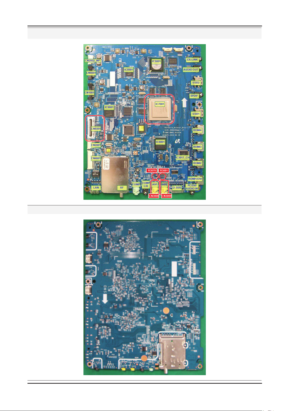
4-20
4. Troubleshooting
Location (Main) - TOP
Location (Main) - BOTTOM
Page 28
4-21
4. Troubleshooting
WAVEFORMS
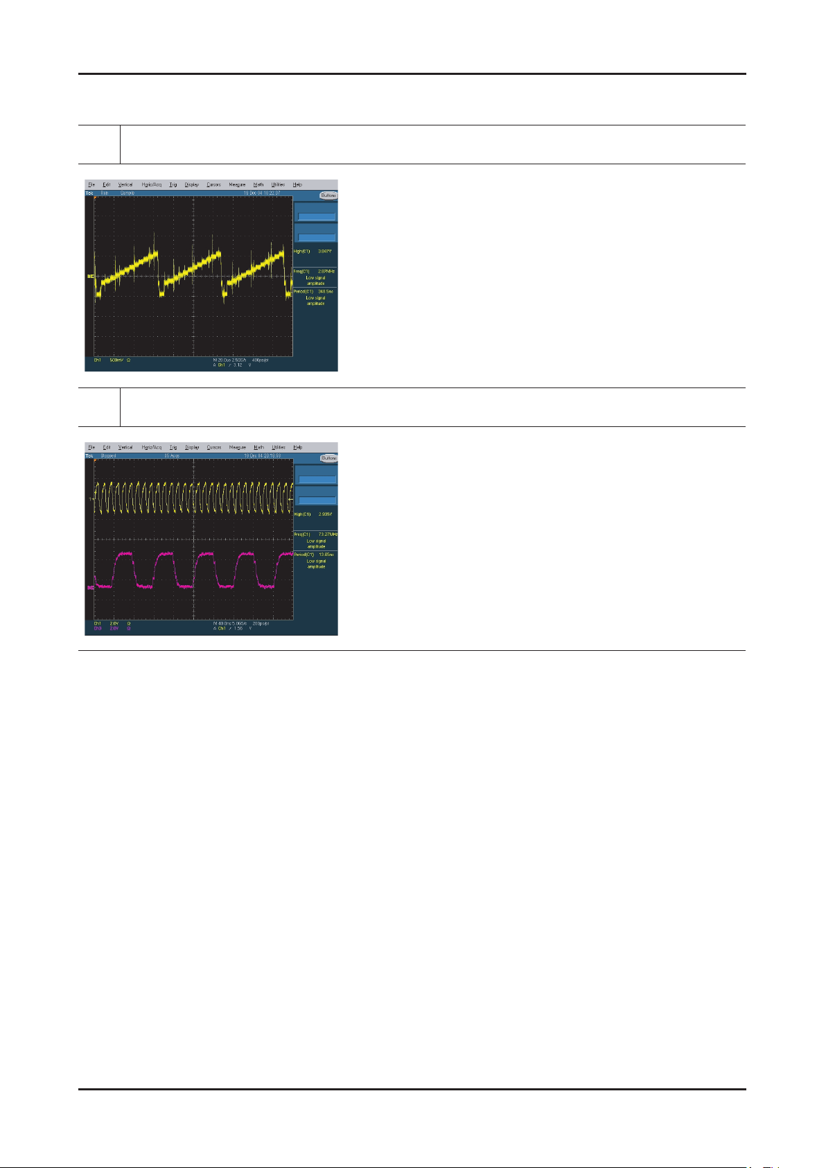
Tuner CVBS Out (Pattern: Grey Bar)
6
Eagle+ Out (Clk, H-Sync)
7
Page 29
4-22
4. Troubleshooting
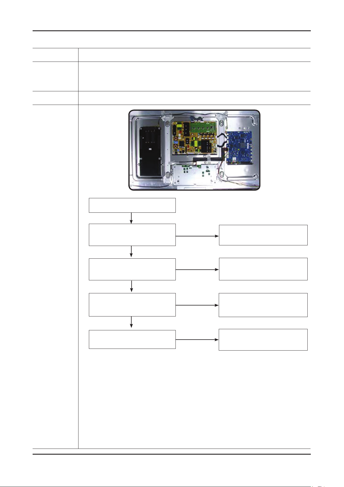
4-1-6. No Video (Component)
Symptom Audio is normal but no picture is displayed on the screen. -
Major
checkpoints
Caution Make sure to disconnect the power before working on the PD board.
Check the Component source -
Check the Valencia -
This may happen when the LVDS cable connecting the Main Board and the Panel is disconnected. -
No video
Yes
Check component source and
check the connection of
component cable ?
Yes
No
Input a component signal.
Check the connected cable.
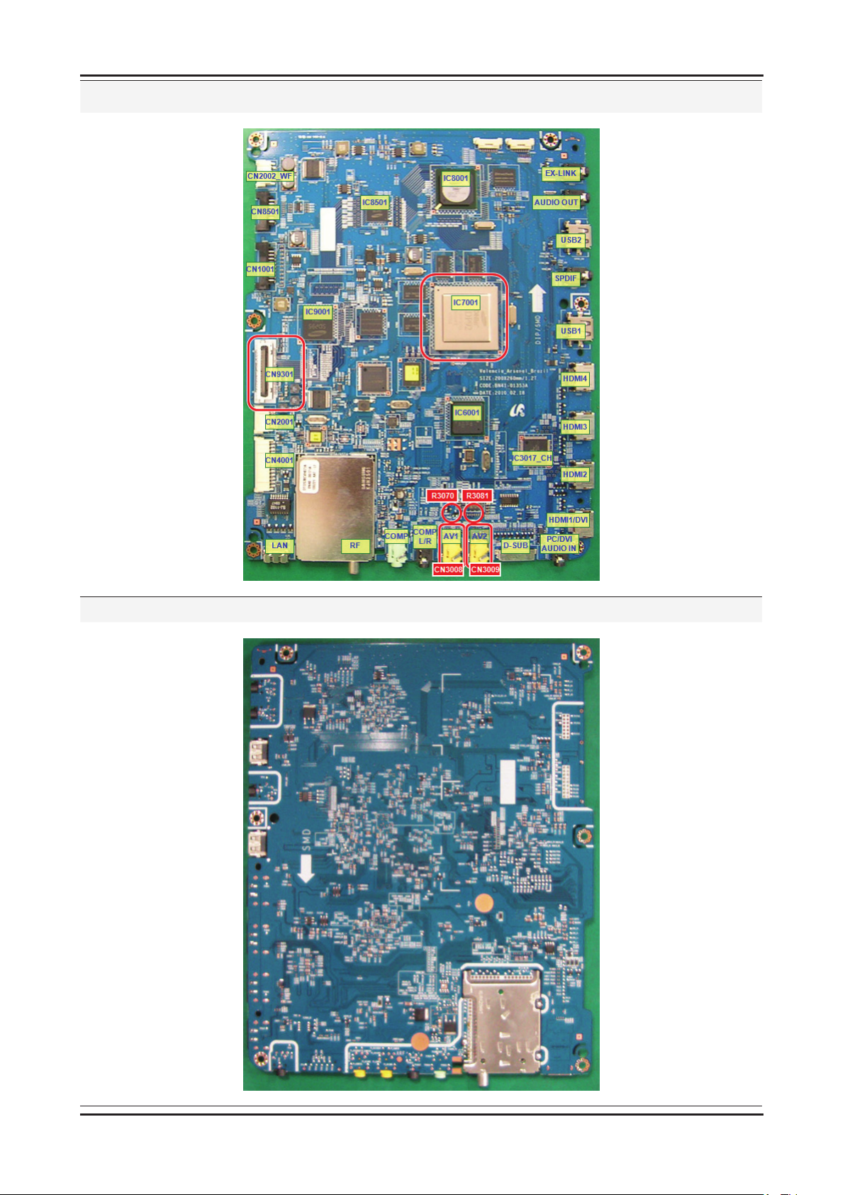
Diagnostics
9
7
Does the signal appear at
R3064, 3065, 3066(Y,Pb,Pr)?
Yes
Does the digital data appear at
pin 15~81 of CN9301?
Yes
Check the LVDS cable?
Replace the LCD panel?
No
No
No
Change the CN3004 or
the main PCB assy.
Change the IC7001 or
the main PCB assembly.
Please, contact Tech support.
Page 30
4-23
4. Troubleshooting
Location (Main) - TOP
Location (Main) - BOTTOM
Page 31
4-24
4. Troubleshooting
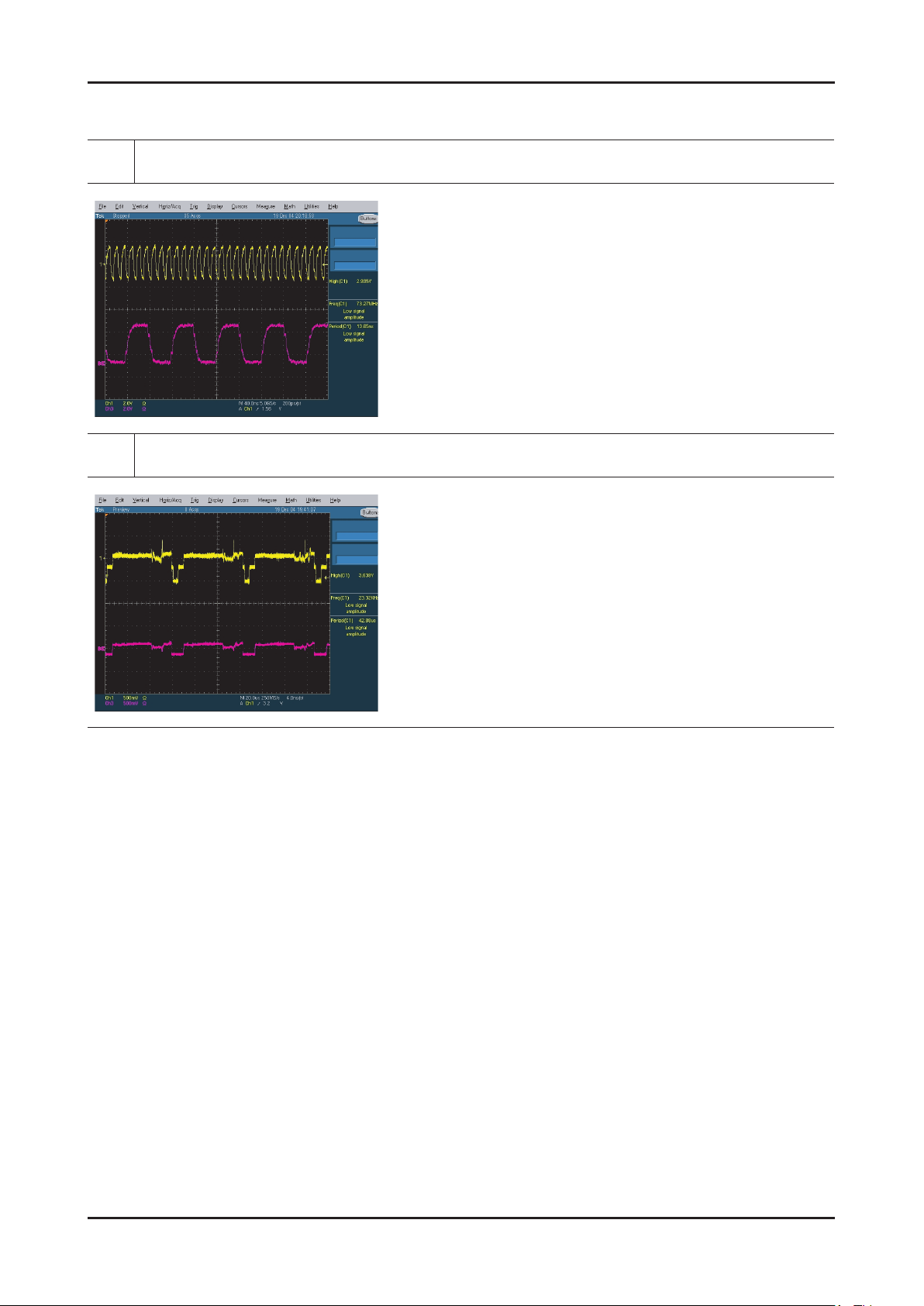
WAVEFORMS
Eagle+ Out (Clk, H-Sync)
7
Component Input (Y/Pb)
9
Page 32
4-25
4. Troubleshooting
4-1-7. No Sound
Symptom Video is normal but there is no sound.. -
Major
checkpoints
Caution Make sure to disconnect the power before working on the PD board.
When the speaker connectors are disconnected or damaged. -
When the sound processing part of the Main Board is not functioning. -
Speaker defect.. -
No sound
Yes
Check the sound source and
check the connection of
sound cable?
Yes
No
Input a sound signal.
Check the connected cable.
Diagnostics
0
!
@
Does the signal appear at
R3069/R3071 or R3080/R3082 ?
Yes
Does the digital data
appear at RA7310 PIN 1, 3, 5, 7?
Yes
Does the signal appear at
pin1~4 of CN2001?
Yes
Check the LVDS cable?
Replace the speaker?
No
No
No
No
Change the CN3004 or
the main PCB assy.
Change IC7001 or
the main PCB assembly.
Change IC2002 or
the main PCB assembly.
Please, contact Tech support.
Page 33
4-26
4. Troubleshooting
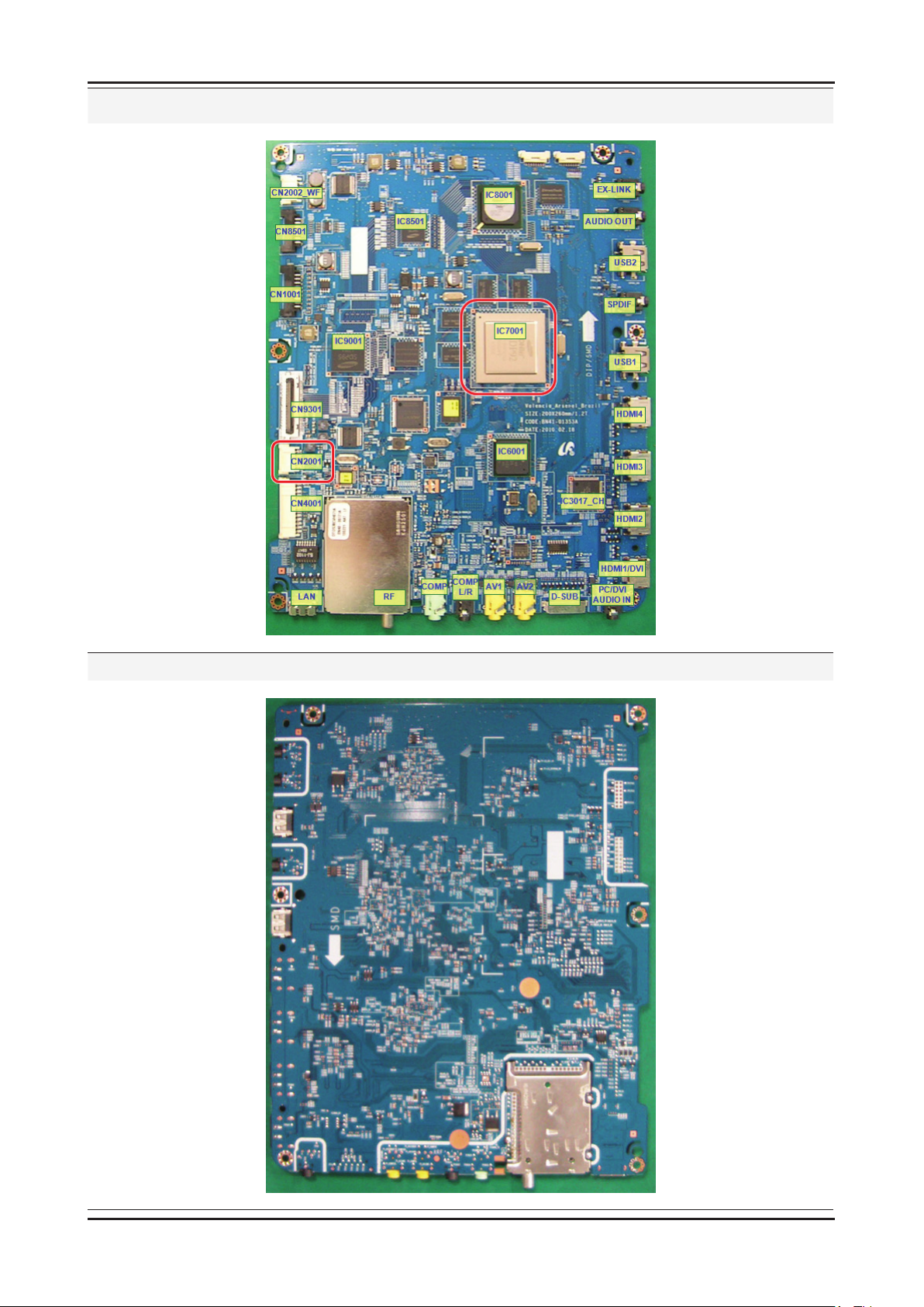
Location (Main) - TOP
Location (Main) - BOTTOM
Page 34
4-27
4. Troubleshooting
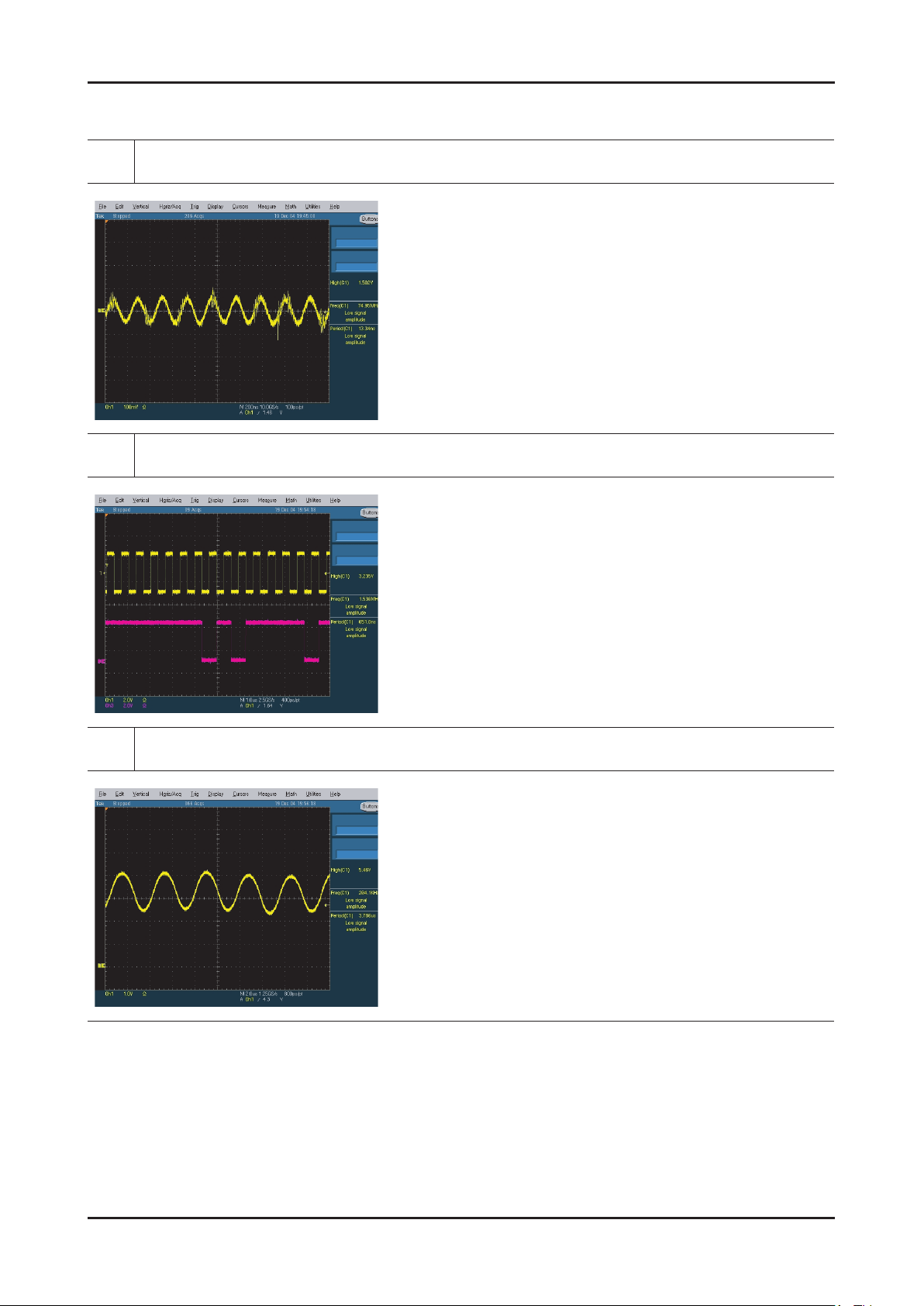
WAVEFORMS
Audio Input (Sign Wave)
0
I2S Input (Clk, Data)
!
Audio Amp Out (Sign Wave)
@
Page 35
4-28
4. Troubleshooting
4-1-8. Reference
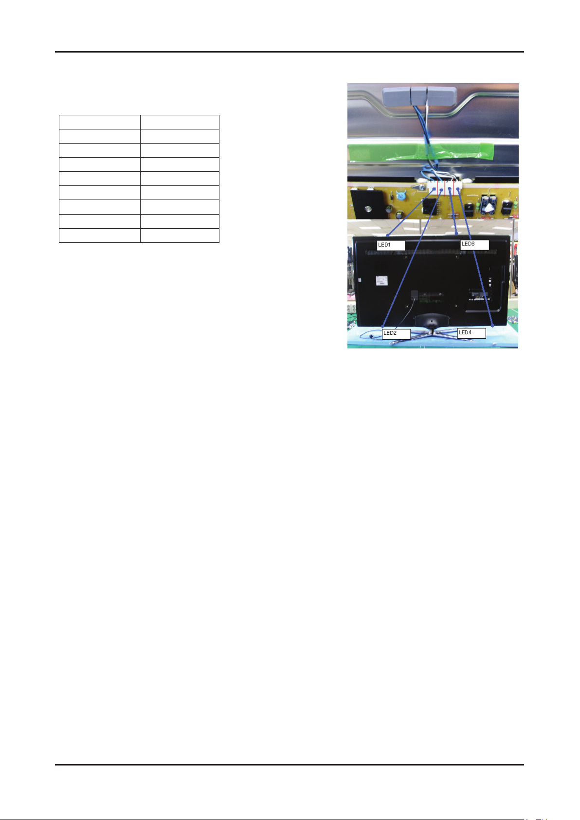
Output CNT which run Edge Led
Refer to the picure and pin map for matching each LED part of connector.
PIN # Signal
1 led1+
2 led1-
3 led2+
4 led2-
5 led3+
6 led3-
7 led4+
8 led4-
Page 36
4-29
4. Troubleshooting
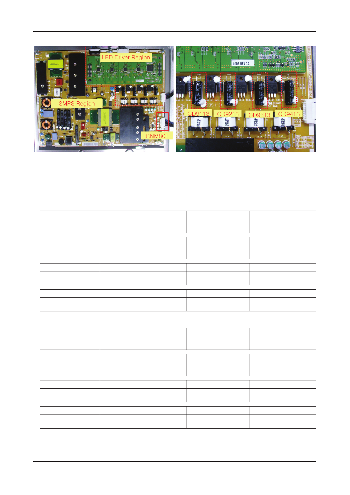
UC8000 PD BOARD DIAGNOSIS
General PD board Diagnosis1.
Disconnect the wire between PD board and Main board.
Short Circuit 16pin and 18pin of CNM801 ▶ If the BLU on , we can consider PD board is acting correctly.
LED Driver output diagnosis2.
Measure voltage at CD9113, CD9213, CD9313, CD9413 which are criteria for judgement.
46" LED Driver output criteria for judgemen
Voltage at CD9113 17~19V 22~33V 39~41V
Judgement
Voltage at CD9213 17~19V 22~33V 39~41V
Judgement
Voltage at CD9313 17~19V 22~33V 39~41V
Judgement
Voltage at CD9413 17~19V 22~33V 39~41V
Judgement
55" LED Driver output criteria for judgement
Voltage at CD9113 23~25V 27~36V 49~51V
Judgement
Voltage at CD9213 23~25V 27~36V 49~51V
Judgement
PD board is out of order.
(Bottom right LED driver is out of order)
PD board is out of order.
(Bottom right LED driver is out of order)
PD board is out of order.
(Bottom right LED driver is out of order)
PD board is out of order.
(Bottom right LED driver is out of order)
PD board is out of order.
(Bottom right LED driver is out of order)
PD board is out of order.
(Bottom right LED driver is out of order)
PD board is acting normally. Bottom LED bar wire is down.
PD board is acting normally. Bottom LED bar wire is down.
PD board is acting normally. Bottom LED bar wire is down.
PD board is acting normally. Bottom LED bar wire is down.
PD board is acting normally. Bottom LED bar wire is down.
PD board is acting normally. Bottom LED bar wire is down.
Voltage at CD9313 23~25V 27~36V 49~51V
Judgement
Voltage at CD9413 23~25V 27~36V 49~51V
Judgement
PD board is out of order.
(Bottom right LED driver is out of order)
PD board is out of order.
(Bottom right LED driver is out of order)
PD board is acting normally. Bottom LED bar wire is down.
PD board is acting normally. Bottom LED bar wire is down.
Page 37
4-30
4. Troubleshooting
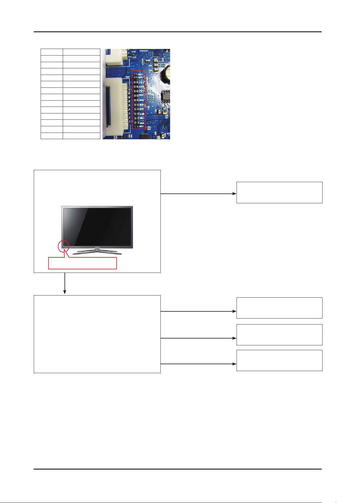
SMPS output diagnosis3.
Measure voltage at below locations for SMPS output diagnosis
BD1032 N240_OVD
BD1040 SW_INVERTER
BD1030 PWM_DIM_1
BD1231 PWM_DIM_2
BD1026 B18VS
BD1028 SW_POWER
BD1023 A5V
BD1024 B5V
BD1022 B5V
BD1025 DGND
BD1021 DGND
BD1020 B13V
BD1018 B13V
BD1029 B13V
When 3D glass seems to have a trouble
Use your mobile phone's camera function for
illuminating in front of 3D emitter
Where 3D emitter locates
IF the 3D emitter blinks
Power on the 3D glass right in front of the 3D emitter
IF the 3D emitter does not blink
IF the 3D glass operates only right
in front of the 3D emitter
IF the 3D glass does not
operates at all
IF the 3D glass operates well
regardless of the distance
TV has a problem.
(3D emitter or Main Board is bad)
3D emitter is bad
3D glass is bad
No problem both 3D emitter and
3D glass
Page 38
4-31
4. Troubleshooting
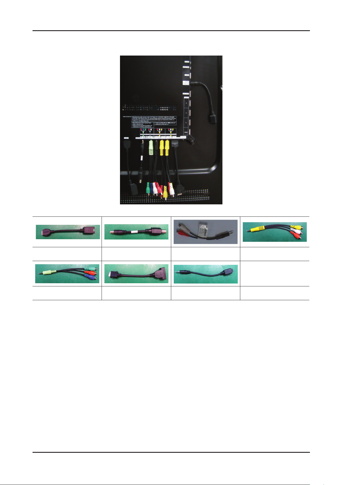
Using Gender Cables
Use gender cables between the TV and connecting devices.
Lan Gender Cable
Component Gender Cable PC Gender Cable Optical Gender Cable
RF Antenna Gender Cable Sound Gender AV Gender Cable
Page 39

4-32
4. Troubleshooting
4-2. Alignments and Adjustments
4-2-1. General Alignment instruction
Usually, a color LCD-TV needs only slight touch-up adjustment upon installation. 1.
Check the basic characteristics such as height, horizontal and vertical sync.
Use the specied test equipment or its equivalent.2.
Correct impedance matching is essential.3.
Avoid overload. Excessive signal from a sweep generator might overload the front-end 4.
of the TV. When inserting signal markers, do not allow the marker generator to distort test result.
Connect the TV only to an AC power source with voltage and frequency as specied on 5.
the backcover nameplate.
Do not attempt to connect or disconnect any wire while the TV is turned on. Make sure 6.
that the power cord is disconnected before replacing any parts.
To protect against shock hazard, use an isolation transformer.7.
Page 40
4-33
4. Troubleshooting
4-3. Factory Mode Adjustments
4-3-1 Entering Factory Mode
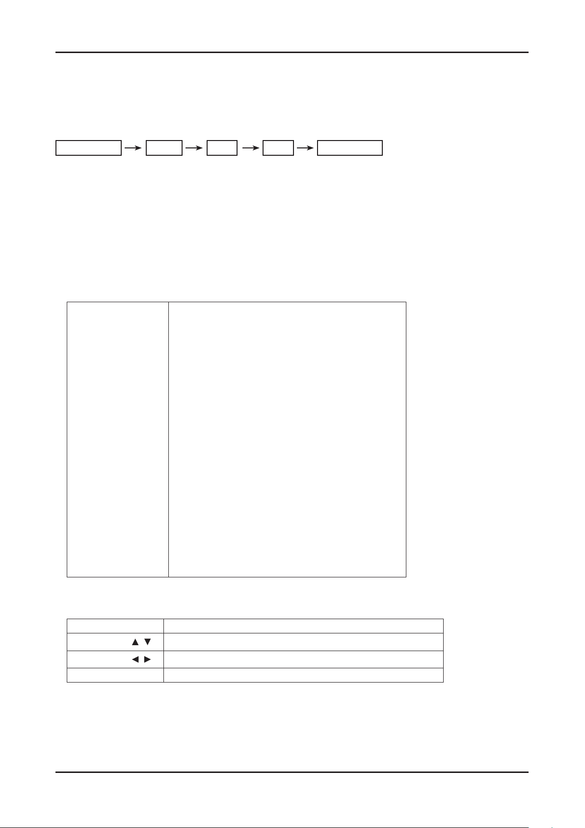
To enter ‘Service Mode’ Press the remote -control keys in this sequence :
- If you do not have Factory remote - control
MUTE 8 2 Power On
1
4-3-2 How to Access Service Mode
Using the Customer Remote
Turn the power off and set to stand-by mode1.
Press the remote buttons in this order; POWER OFF-MUTE-1-8-2-POWER ON to turn the set on.2.
The set turns on and enters service mode. This may take approximately 20 seconds.3.
Press the Power button to exit and store data in memory. 4.
- If you fail to enter service mode, repeat steps 1 and 2 above.
Initial SERVICE MODE DISPLAY State 5.
Mode : CATV , RES : NOSIGNAL
Option
Control
SVC
Expert
ADC/WB
Advanced
T-VALDAAC-0078
T-VALDAAS-0230
EDID SUCCESS
CALIB : AV X COMP X PC O HDMI O
Option : 0000 1100 10
DTP-SP-VAL-1048
RFS:42-42
2009-12-25
FRCS FW : 0111, CONFIG : 6D00
N240:0006
READING : 2010
Type : NONE
Model : UA**C8000
MAC SUCCESS
Factory Data Ver : 189
EERC Version : 81
DTP-AP-COMP-340
DTP-HIIG-0335
DTP-BP-0343-01
Date of purchase : --/--/----
Buttons operations withn Service Mode 6.
Menu Full Menu Display/Move to Parent Menu
Direction Keys
Direction Keys
Source
Item Selection by Moving the Cursor
/
Data Increase / Decrease for the Selected Item
/
Cycles through the active input source that are connected to the unit
Page 41

4-34
4. Troubleshooting
4-3-3 How to Access ‘EDID SUCCESS’ Mode
At initial SERVICE MODE DISPLAY state, you’ll see ‘EDID SUCCESS’.
- If not, go to
Control
And follow the procedure.
Set 1. ON at EDID ON/OFF menu.
At 2. EDID WRITE ALL menu, press ▶key of the remote control. After few seconds Success will appear.
If 3. Failure appears, remove the PC cable and HDMI cable that connected to TV. And try it again.
If the problem still exists, go to 4. HDMI EDID Ver menu, and change the HDMI version to HDMI 1.2 or HDMI 1.3.
Change the Main Board if same problem occurs.5.
EDID
Page 42
4-35
4. Troubleshooting
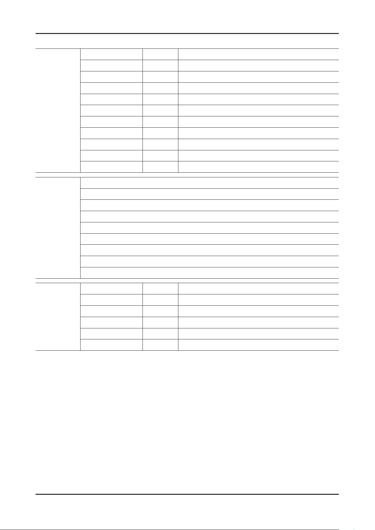
4-3-4 Factory Data
Option
Control
Factory Name Data Range
Factory Reset
Type 40A2UF8E/46A2UF8E/55A2UF8E/65L2UF8E
Local Set ...
Model UC8000
Tuner SEC_ISDB_T
DDR
Light Effect OFF
Ch Table ...
Country
Front Color W-Milky
Factory Name
EDID
Sub Option
PDP Option
Shop Option
EDID
Asia Option
SOUND
Cong Option
SSC
Factory Name Data Range
EDID ON/OFF ON/OFF
EDID WRITE ALL Success/Failure
EDID WRITE PC Success/Failure
HDMI EDID Ver HDMI1.2/HDMI1.3
HDMI EDID Port NONE/Not Support/HDMI2/HDMI3/HDMI4
Page 43
4-36
4. Troubleshooting
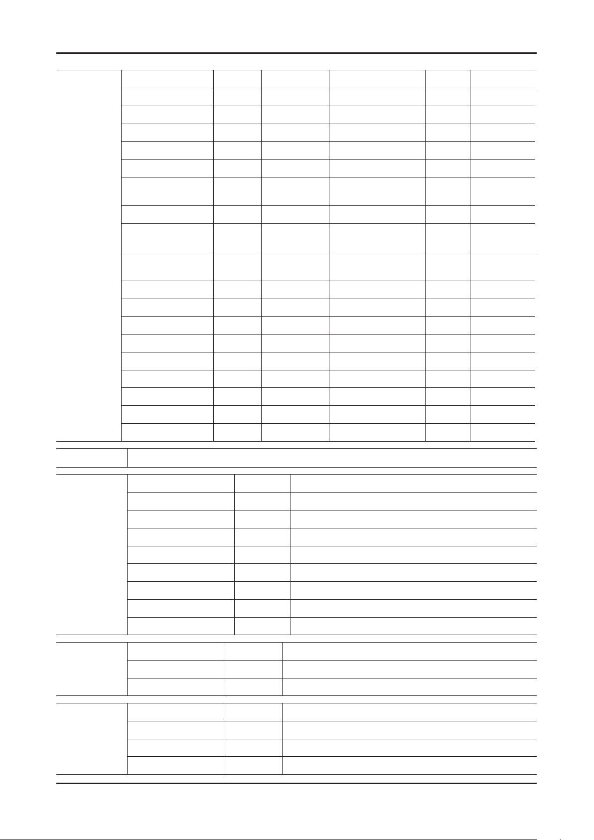
Sub Option
Factory Name Data Range Factory Name Data Range
Region Brazil Info Link Server Type development
PnP Language ... TTX List ...
RF Mute Time 0ms TTX Group ...
RS-232 Jack Debug ND ADJ Support ON
Watchdog OFF 24Px4 Support ON
WD COUNT 0 Power Indicator
Support
Dimm Type EXT BD Wise Support ON
LVDS FORMAT VESA RF Remocon
Support
Language_Arabic ... Data Service
Support
TOOLS Support 31 PVR Support OFF
LNA Support OFF 3D Support ON
CI Support OFF Gemstar Support OFF
MediaPlay Movie with chapteri WSS Support ...
DLNA ON OTA Duration Test OFF
ON
OFF
OFF
PDP Option
Hotel
Option
Shop
Option
DB On with 10MB Alternate Del OFF
Play List ON
NETWORK Support Wireless
Info Link Country USA
Factory Name Data Range
Hotel MODE ON
POWER ON CHANNEL 3
CHANNEL TYPE DTV
POWER ON VOLUME 10
MIN VOLUME 0
MAX VOLUME 100
PANEL BUTTON LOCK Unlock
POWER ON SOURCE TV
Factory Name Data Range
Shop Mode OFF
Asia Option
Exhibition Mode OFF
Factory Name Data Range
TTX OFF
China HD OFF
NT Conversion OFF
Page 44
4-37
4. Troubleshooting
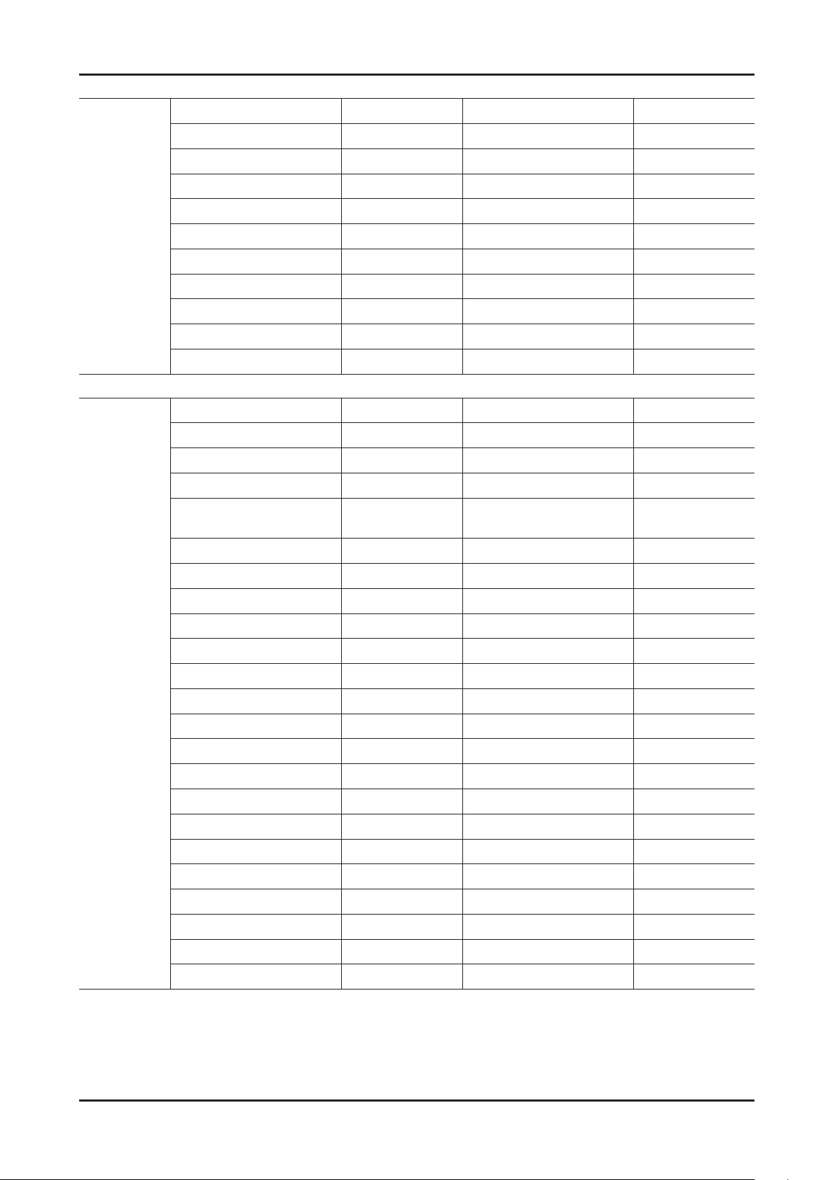
SOUND
Cong
Option
Factory Name Range Factory Name Range
High Devi OFF STA Amp Scale 0x5Eh
Carrier Mute ON/OFF STA Woofer Scale 0x6Eh
Volume Curve Type1 STA Speaker EQ ON/OFF
Pilot Level High Thld 0x30h STA Sub Woofer 4
Pilot Level Low Thld 0x10h STA EQ CheckSum TW 0xA86138
Chattering Cnt 5 STA EQ CheckSum WF
FM Prescale 0x14h STA PEQ Test Ready
AM Prescale 0x1Ah STA PEQ Dump
NICAM Prescale 0x14h SPDIF PCM Level -8
STA Amp Volume 0x3Fh
Factory Name Range Factory Name Range
Num of ATV 1 DVI/HDMI SOUND Auto
Num of DTV 1 HDMI HOT PLUG Disable
Num of AV 1 HOTPLUG SWITCHING Boot
Num of SVIDEO 0 HOT PLUG OFF HOLD
TIME
1200ms
Num of COMP 1 HDMI FLT CNT SIG 100ms
Num of HDMI 4 HDMI FLT CNT LOS 100ms
Num of PC 1 UNSTABLE BAN CNT 1250ms
Num of SCART 0 HDMI Err Cnt 1
Num of DVI 0 HDMI ROBIN ON
Num of OPTICAL Link 0 HDMI Callback ON
Num of MEDIA 1 HDMI CTS Thld 0
Num of PANEL KEY 6 HDMI CTS Cnt1 0
Num of USB Port 2 HDMI 3D Det 1
MFT Offset 62.5 TMDS_EQ2_Boost 1
Select LCD/PDP LCD TMDS_EQ2_Gain 10
Num of DECODER 1 TMDS_PLL_Loop 3
Num of TUNER 1 TMDS_CPREG_BLEED 1
HDMI/DVI SEL 1 HDMI EQ AUTO
Indicator Led ON/OFF HDMI EDID CTRL Type Combine
Wall Mount OFF DVI SET TIME 300ms
HV Flip ON/OFF Type Of PANEL KEY Horizontal
Num Of Display 2 LD CTRL SELECT LIMIT_CTRL
Page 45
4-38
4. Troubleshooting
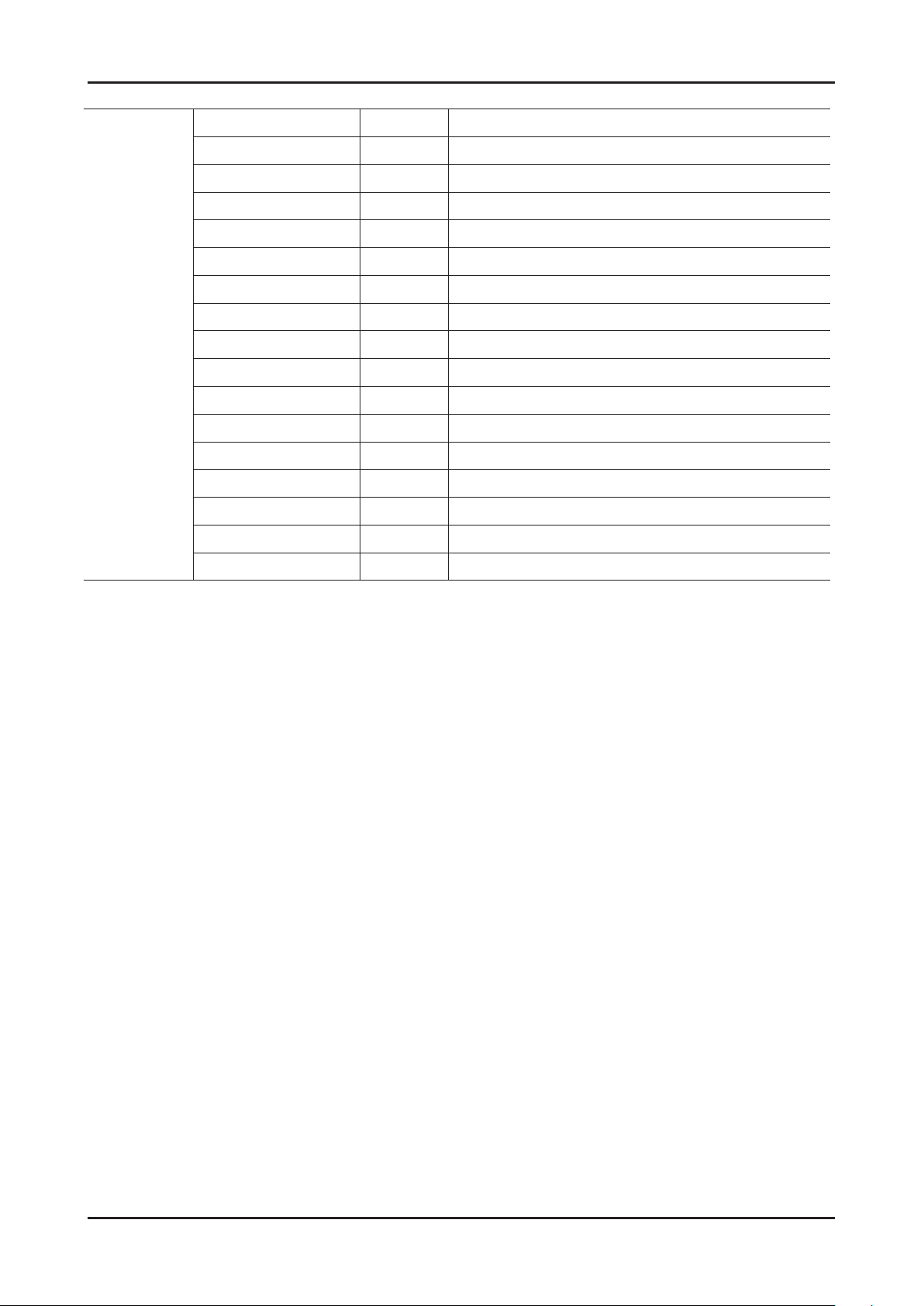
SSC
Factory Name Data Range
SCC Mode
SSC ON/OFF
SSC Input Data Hx 272
Hy 278
Lx 272
Ly 278
Sscc Const sSCC Hx 548
sSCC Hy 591
sSCC Lx 546
sSCC Ly 585
pSCC Const pSCC Hx 548
pSCC Hy 591
pSCC Lx 546
pSCC Ly 558
SCC Source Data PBA
Swap PBA
Page 46
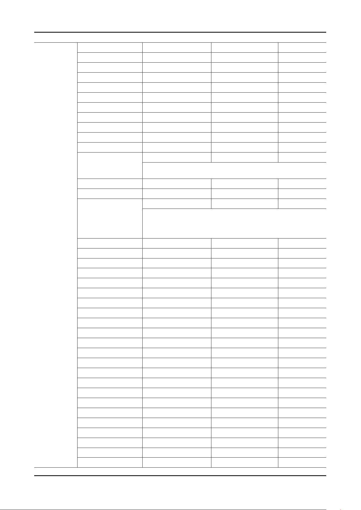
4-39
4. Troubleshooting
SVC
Factory Name Range Factory Name Range
Test Pattern FBE Pattern Sel 0
LOGIC Pattern Sel 0
LOGIC Level Sel 255
READ PRE_PATT_SEL 0
READ POST_PATT_SEL 0
Reading PC Mode OFF
LDAsic Pattern Sel 0
FRCS Patt before DDR 0
FRCS Patt after DDR 0
FRCS PC Mode On/Off OFF
Failure
Panel Auto Setting
PANEL DISPLAY TIME -14Hr
LOGIC USB D/L ...
T-CON USB Download
TC905x7 TC90507 FFT Size_0 0
Press ▶ and the Main Board will automatically read type of the Panel.
When change Main Board or Panel this menu will be helpful.
Failure 0
You can upgrade T-con program via USB. Put a upgrading le in USB
memory stick and insert it in USB1 or USB2 connector of the TV.
And press ▶ at the T-CON USB Download menu and it will download
the upgrading le from the USB memory stick.
Guard Interval_0 0
Freq. Offset_0 0
SNR_0 0
IF AGC_0 0
TMCC Lock_0 0
TS Packet_0 0
Master Lock_0 0
A_Modulation_0 0
A_Code Rate_0 0
A_Timer InterLeave_0 0
A_Segments Num_0 0
A_BER_0 0
B_Modulation_0 0
B_Code Rate_0 0
B_Timer InterLeave_0 0
B_Segments Num_0 0
B_BER_0 0
C_Modulation_0 0
C_Code Rate_0 0
C_Timer InterLeave_0 0
C_Segments Num_0 0
C_BER_0
Page 47
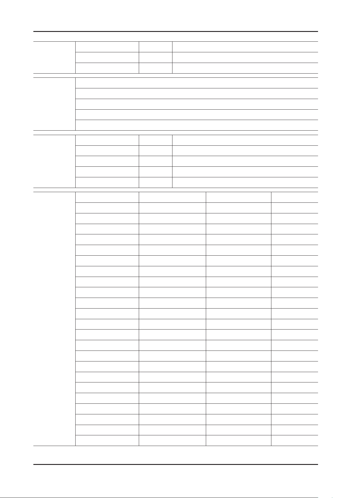
4-40
4. Troubleshooting
Expert
ADC/WB
ADC
ADC Result
Factory Name Data Range
N/D ADJ OFF
Source ...
Factory Name
ADC
ADC Target
ADC Result
White Balance
Factory Name Data Range
AV Calibration Failure
Comp Calibraion Failure
PC Calibration Success
HDMI Calibration Success
Factory Name Range Factory Name Range
1st_AV_Low 64 2nd_AV_B_High 940
1st_AV_High 880 2nd_AV_Delta 1
1st_AV_Delta 1 2nd_COMP_R_Low 4
1st_COMP_Y_Low 64 2nd_COMP_G_Low 4
1st_COMP_Cb_Low 512 2nd_COMP_B_Low 4
1st_COMP_Cr_Low 512 2nd_COMP_R_High 940
1st_COMP_Y_High 940 2nd_COMP_G_High 940
1st_COMP_Cb_High 512 2nd_COMP_B_High 940
1st_COMP_Cr_High 512 2nd_COMP_Delta 1
1st_COMP_Delta 1 2nd_PC_R_Low 4
1st_PC_R_Low 16 2nd_PC_G_Low 4
1st_PC_G_Low 16 2nd_PC_B_Low 4
1st_PC_B_Low 16 2nd_PC_R_High 940
1st_PC_R_High 1004 2nd_PC_G_High 940
1st_PC_G_High 1004 2nd_PC_B_High 940
1st_PC_B_High 2nd_PC_Delta 1
1st_PC_B_High 1004 2nd_HDMI_R_Low 4
1st_PC_Delta 1 2nd_HDMI_G_Low 4
2nd_AV_R_Low 4 2nd_HDMI_B_Low 4
2nd_AV_G_Low 4 2nd_HDMI_R_High 940
2nd_AV_B_Low 4 2nd_HDMI_G_High 940
2nd_AV_R_High 940 2nd_HDMI_B_High 940
2nd_AV_G_High 940 2nd_HDMI_Delta 1
Page 48
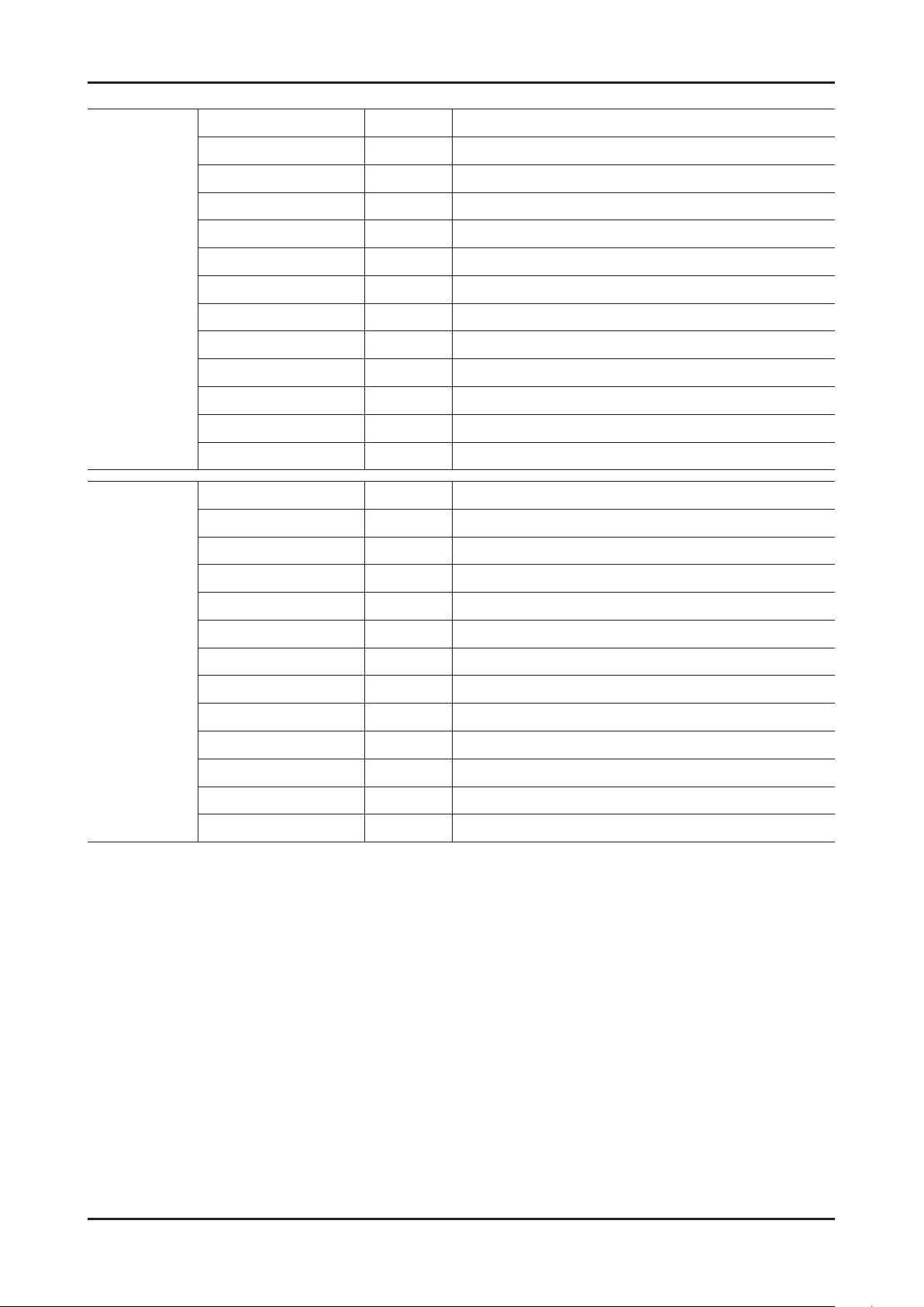
4-41
4. Troubleshooting
ADC Result
White
Balance
Factory Name Data Range
1st_Y_GH 250
1st_Y_GL 245
1st_Cb_BH ...
1st_Cb_BL ...
1st_Cr_RH ...
1st_Cr_RL ...
2nd_R_L 131
2nd_G_L 131
2nd_B_L 131
2nd_R_H 107
2nd_G_H 107
2nd_B_H 107
Factory Name Data Range
Sub Brightness 128
R-Offset 512
G-Offset 512
B-Offset 512
Sub Contrast 128
R-Gain 548
G-Gain 512
B-Gain 520
Movie R-Offset ...
Movie B-Offset ...
Movie R-Gain ...
Movie B-Gain ...
Page 49
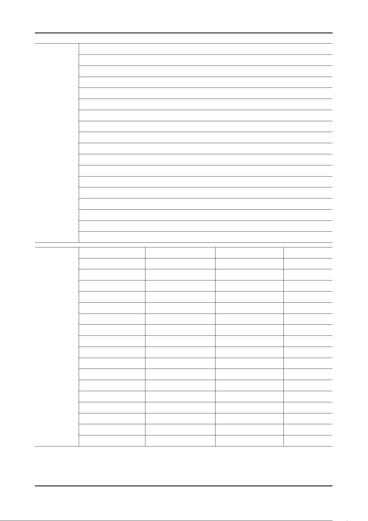
4-42
4. Troubleshooting
Advanced
Factory Name
Picture
FBE3
WB Movie
SubSetting
Color Mapping
EPA 3D
CH_VDEC
AR_ADC
YC_Delay
Sharpness
Sharpness_LNA
LNA_Plus
LD Asic
3D
Reading
LED Driver
FBE3
FRC
Factory Name Range Factory Name Range
BM_slope 44 LFUNC_OUT3 95
BM_start 40 LFUNC_OUT4 132
BM_start_max 110 LFUNC_OUT5 132
Lfunc_gain 128 UFUNC_TH1 17
Hfunc_gain 128 UFUNC_TH2 95
ACR-Offset 10 UFUNC_TH3 178
Skin-UV 136 UFUNC_OUT2 45
FBE Sub color 132 UFUNC_OUT3 75
M-Skin-UV 138 UFUNC_OUT4 255
M-Sub Color 128 UFUNC_OUT5 255
N_Skin_UV 128 PPHC_Red 0
N_Sub_Gamma 0 PPHC_Green 7
Color Gamut 128 PPHC_Blue 0
LFUNC_TH1 28 PPHC_Cyan 10
LFUNC_TH2 70 PPHC_Magenta -5
LFUNC_TH3 130 PPHC_Yellow -8
LFUNC_OUT2 12
Page 50
4-43
4. Troubleshooting
WB Movie
SubSetting
Factory Name Range Factory Name Range
W/B MOVIE ON/OFF ON/OFF W2_Rgain ...
MODE Dynamic W2_Bgain ...
Color Tone ... W2_Roffset ...
MSub Brightness ... W2_Boffset ...
MSub Contrast ... Movie Contrast ...
N_Rgain ... Movie Bright ...
N_Bgain ... Movie Color ...
N_Roffset ... Movie Sharpness ...
N_Boffset ... Movie Tint ...
W1_Rgain ... Movie Backlight ...
W1_Bgain ... Movie Gamma ...
W1_Roffset ... M_Sub_Gamma ...
W1_Boffset ... HDMI Black Level ...
Factory Name Data Range
Gamma 0.95
Color
Mapping
PWM Max 100
PWM Mid 10
PWM Min 0
Contrast Dimming OFF
7.5 IRE NTSC OFF
7.5 IRE OFFSET ...
48Hz Enable OFF
Peak Dimming ON
Dynamic CE ON
Factory Name Range Factory Name Range
Auto_Red_R 50 Auto_Yellow_R 50
Auto_Red_G 0 Auto_Yellow_G 50
Auto_Red_B 0 Auto_Yellow_B 0
Auto_Green_R 0 Auto_Cyan_R 0
Auto_Green_G 50 Auto_Cyan_G 50
Auto_Green_B 0 Auto_Cyan_B 50
Auto_Blue_R 0 Auto_Magenta_R 50
Auto_Blue_G 0 Auto_Magenta_G 0
Auto_Blue_B 50 Auto_Magenta_B 50
Page 51
4-44
4. Troubleshooting
EPA 3D
CH_VDEC
Factory Name Range Factory Name Range
Standard Contrast 95 V_3D PWM Delay_60 179
Standard Brightness 45 V_3D ANA Delay_60 305
Standard Sharpness 50 V_3D PWM Delay_50 161
Standard Color 50 V_3D ANA Delay_50 274
Standard Tint 0 Motion plus Delay 249
Standard Backlight 14 Home Delay 0
3D Contrast 95 Shop Delay 511
3D Brightness 45
Factory Name Range Factory Name Range
AGC_mode 1 ST_Beg_NTSC 0
Gain_VCR 0 VS_Slice_Level 4
Y_Gain_Man 880 HS_Slice_Level 3
Y_Shape_sel 13 FB_Delay_adj 0
Y_Shape_SCM 29 RGB_Delay_adj 0
C_Shape_sel 4 slice_mod_ne 0
AR_ADC
YC_Delay
C_Shape_SCM 4 scm_fdet_lvl 150
If_iir 0 bl_range 3
If_lt_sel 6
Factory Name Data Range
PHASE 16
SOG_BW 3
SSC_PC 10
RGB_DLY 0
Factory Name Range Factory Name Range
PAL_BG 0 NTSC_443 0
PAL_DK 0 AV_PAL 0
PAL_I 0 AV_PAL_M 0
PAL_M 0 AV_PAL_N 0
PAL_N 0 AV_SECAM 0
SECAM_BG 0 AV_NT358 0
SECAM_DK 0 AV_NT443 0
SECAM_L 0 AV_PAL60 0
NTSC_358 0
Page 52
4-45
4. Troubleshooting
CH_DP
Sharpness
Factory Name Range Factory Name Range
BD_MAX_PERCENT_X 45 BD_TOUCH_SUP_INV 24
BD_MAX_PERCENT_Y 40 DR_SIGMA_FIL_GAIN 20
BD_DETAIL_AMT_MAX 24 DR_GAIN_IN_ETE 8
BD_TOUCH_SUPP 8 SD2HD_Metric 227
Factory Name Range Factory Name Range
Pre_GainH1 12 Post_GainPE2 100
Pre_GainH2 15 Post_GainPV1 55
Pre_GainH3 18 Post_GainPV2 80
Pre_GainV1 15 CTI_Gain 15
Pre_GainV2 15 Pre_LTIH 10
Pre_GainV3 8 LTI_H 20
Post_GainH1 24 LTI_V 12
Post_GainH2 36 PRE_CORING_H 6
Post_GainH3 0 PRE_CORING_V 6
Post_GainV1 20 POST_CORING 2
Post_GainV2 32 Pre_TOT 12
Post_GainV3 0 Post_TOT 32
Post_GainPE1 75 SH Sub Color 59
Page 53
4-46
4. Troubleshooting
Sharpness_
LNA
Factory Name Range Factory Name Range
S1_Pre_GainH1 7 S2_Post_GainH3 0
S1_Pre_GainH2 9 S2_Post_GainV1 8
S1_Pre_GainH3 10 S2_Post_GainV2 12
S1_Pre_GainV1 9 S2_Post_GainV3 0
S1_Pre_GainV2 9 S2_Post_GainPE1 30
S1_Pre_GainV3 4 S2_Post_GainPE2 40
S1_Post_GainH1 14 S2_Post_GainPV1 22
S1_Post_GainH2 21 S2_Post_GainPV2 32
S1_Post_GainH3 0 S3_Pre_GainH1 1
S1_Post_GainV1 12 S3_Pre_GainH2 1
S1_Post_GainV2 19 S3_Pre_GainH3 1
S1_Post_GainV3 0 S3_Pre_GainV1 1
S1_Post_GainPE1 45 S3_Pre_GainV2 1
S1_Post_GainPE2 60 S3_Pre_GainV3 0
S1_Post_GainPV1 33 S3_Post_GainH1 2
S1_Post_GainPV2 48 S3_Post_GainH2 3
LNA_Plus
LD Asic
S2_Pre_GainH1 4 S3_Post_GainH3 0
S2_Pre_GainH2 6 S3_Post_GainV1 2
S2_Pre_GainH3 7 S3_Post_GainV2 3
S2_Pre_GainV1 6 S3_Post_GainV3 0
S2_Pre_GainV2 6 S3_Post_GainPE1 7
S2_Pre_GainV3 3 S3_Post_GainPE2 10
S2_Post_GainH1 9 S3_Post_GainPV1 5
S2_Post_GainH2 14 S3_Post_GainPV2 8
Factory Name Range Factory Name Range
FRCS SSC On/Off ON FRCS LVDS BitWidth
FRCS SSC Width 96 FRCS LVDS Sequence
FRCS SSC Freq 240 FRCS Hangup Detection ON
FRCS LVDS Format FRCS FMD Demo OFF
Factory Name Range Factory Name Range
R_LD4_L3DD_RATIO 4 R_ALL_READ 0
R_LD4_LD_ON ON R_LVDS_TX_FMT 1
R_DELAY 0 R_LVDS_SW 0
Page 54
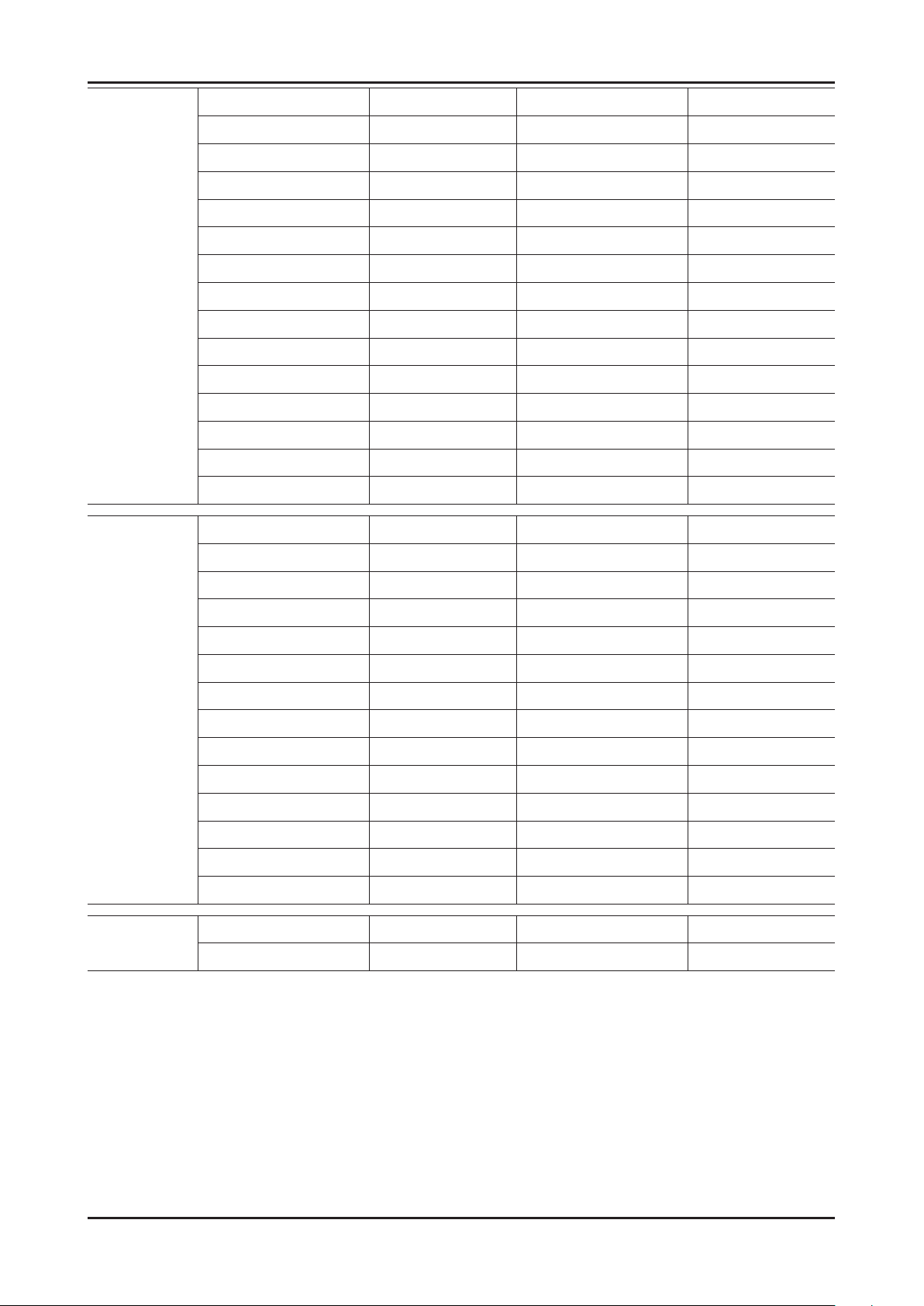
4-47
4. Troubleshooting
3D
Reading
Factory Name Range Factory Name Range
EmitOn ON 2D3D Depth4 40
EmitStartPosi60 2 2D3D Depth5 50
EmitStartPosi50 2 2D3D Depth6 60
EmitStartPosi48 2 2D3D Depth7 70
3DSyncVstart60 275 2D3D Depth8 80
3DSyncVend60 840 2D3D Depth9 90
3DSyncVstart50 275 2D3D Depth10 100
3DSyncVend50 840 N240 PWM Delay_60 0
3DSyncVstart48 275 N240 ANA Delay_60 0
3DSyncVend48 840 N240 PWM Delay_50 0
2D3D Focus 128 N240 ANA Delay_50 0
2D3D Depth1 10 N240 PWM Delay_48 0
2D3D Depth2 20 N240 ANA Delay_48 0
2D3D Depth3 30
Factory Name Range Factory Name Range
LED Driver
POST_FDISPLAY 0 HMVSRMargin_2X_H 6
RAMP_SPEED 1 HMVSRMargin_2X_M 6
POST_RAMP_SPEED 1 HMVSRMargin_2X_L 6
LVDS_RX_FMT 1 VMVSRMargin_2X 2
LVDS_TX_FMT 1 HSADPercentT1_2X 10
LVDS_RX_BIT 1 HSADPercentT2_2X 14
LVDS_TX_BIT 1 HMVSRMargin_FILM_H 6
POST_OUT1_ORDER 0 HMVSRMargin_FILM_M 6
POST_OUT2_ORDER 1 HMVSRMargin_FILM_L 6
POST_OUT3_ORDER 2 VMVSRMargin_FILM 2
POST_OUT4_ORDER 3 HSADPercentT1_FILM 10
CROSS_PATTERN OFF HSADPercentT2_FILM 14
EnableFB 1
Factory Name Range Factory Name Range
VSYNC_DELAY_3D_50 0 VSYNC_DELAY_3D_60 6
Page 55
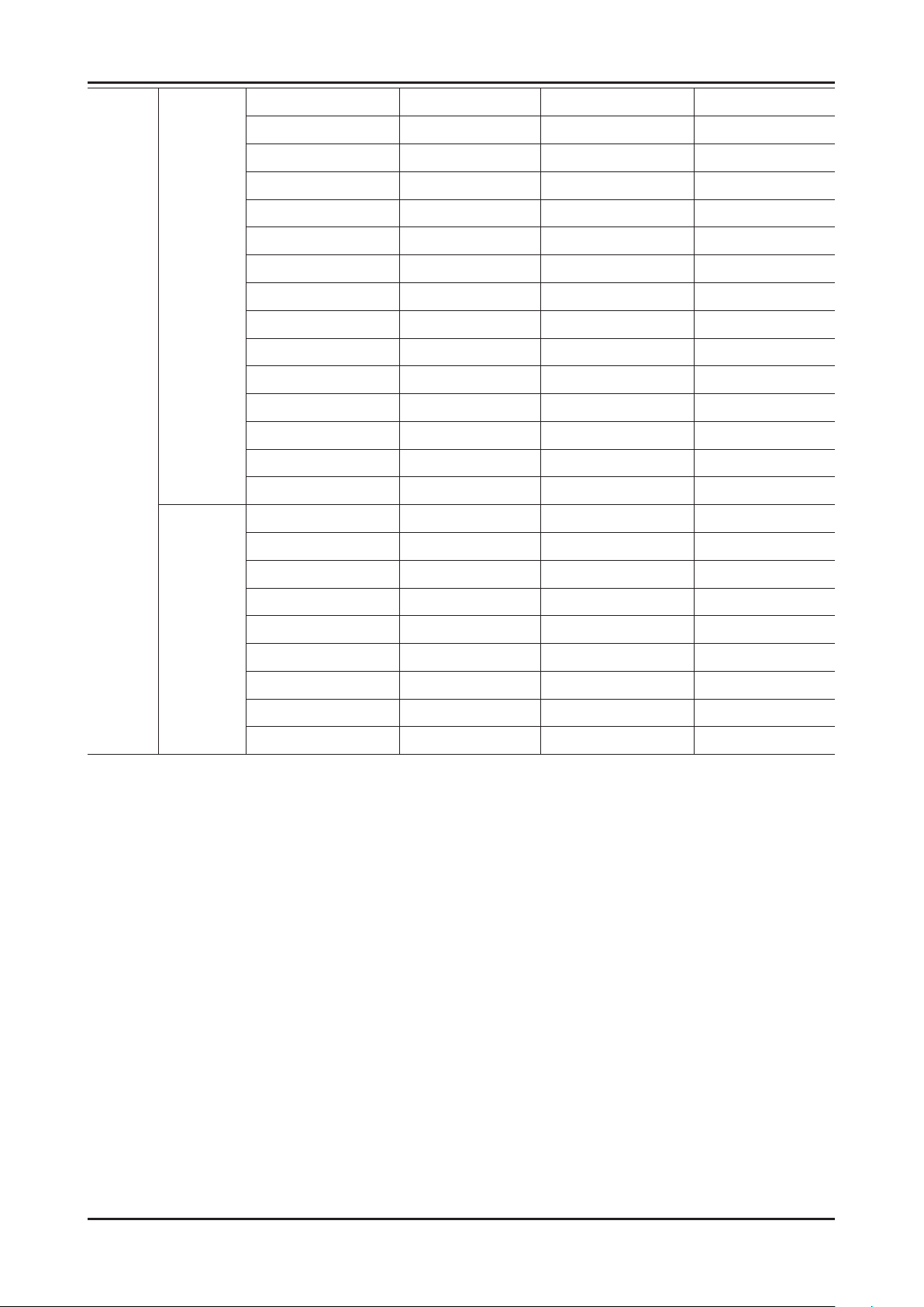
4-48
4. Troubleshooting
FRC
FRCQ
Option
FRCQ
Fallback
Factory Name Range Factory Name Range
SSC_OnOff ON Film_Low_SD 40
SSC_Width 2 Film_Medium_SD 50
SSC_Freq 2 Film_High_SD 60
FMD_Demo 2 Film_Low_HD 70
CSB Vertical 275 Film_Medium_HD 80
CSB Horizontal 840 Film_High_HD 90
X_VStabStatVid 275 Video_Judder_Low 100
X_VStabStatF 840 Video_Judder_Med 0
X_VStabCorF 275 Video_Judder_High 0
X_VStabSensF 840 Hangup Detection 0
X_HaloSizStatVid 128 Q LVDS Sequence 0
X_HaloSizStatF 10 Q LVDS Format 0
X_HaloSizCorF 20 Q LVDS bit width 0
X_HaloSizSensF 30 PC_Mode_OnOff
Factory Name Range Factory Name Range
SensD_Film_Low 31 V_Len_Slope_Film 1
SensD_Film_Medium 31 SensD_Video 0
SensD_Film_High 31 Rel_Start_Video 20
Rel_Start_Film 20 Rel_Slope_Video 1
Rel_Slope_Film 3 H_Len_Start_Video 127
H_Len_Start_Film 127 H_Len_Slope_Video 1
H_Len_Slope_Film 1 V_Len_Start_Video 40
V_Len_Start_Film 40 V_Len_Slope_Video 1
Page 56
4-49
4. Troubleshooting
4-4. White Balance - Calibration
4-4-1 White Balance -Calibration
ADC/WB
ADC
AV Calibration
Comp Calibration
PC Calibration
HDMI Calibration
4-4-2 Service Adjustment
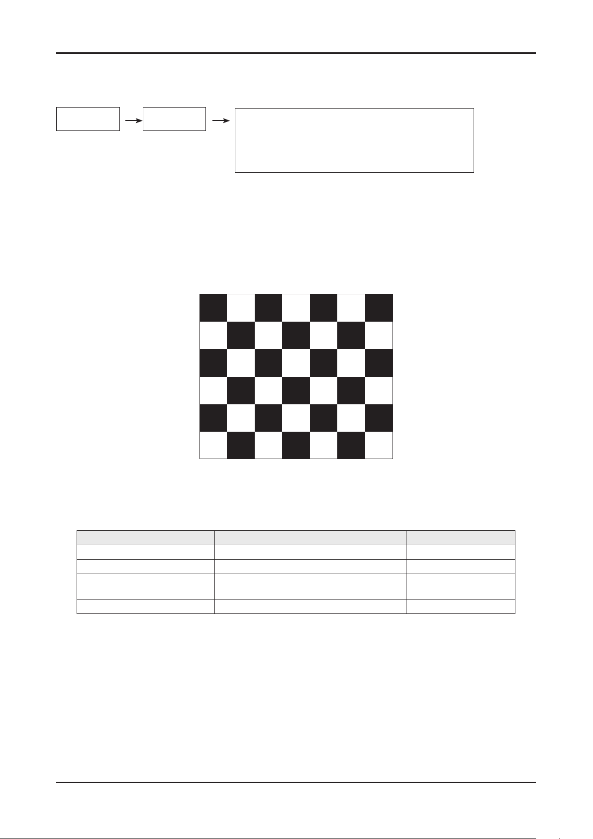
You must perform Calibration in the Lattice Pattern before adjusting the White Balance.
Color Calibration
Adjust spec.
1. Source : HDMI
2. Setting Mode : 1280*720@60Hz
3. Pattern : Pattern #24 (Chess Pattern)
( Chess Pattern )
4. Use Equipment : CA210 & Master MSPG925 Generator
- Use other equipment only after comparing the result with that of the Master equipment.
Input mode Calibration Pattern
CVBS IN (Model_#1) Perform in NTSC B&W Pattern #24 Lattice
Component IN (Model_#6) Perform in 720p B&W Pattern #24 Lattice
PC Analog IN (Model_#21)
HDMI IN Perform in 720p B&W Pattern #24 Lattice
Perform in VESA XGA (1024x768)
B&W Pattern #24
<Table 1>
Lattice
Page 57

4-50
4. Troubleshooting
Method of Color Calibration (AV)
1) Apply the NTSC Lattice (N0. 3) pattern signal to the AV IN 1 port
2) Press the Source key to switch to "AV1" mode
3) Enter Service mode
4) Select the "ADC/WB" and "ADB" menu
5) Select the "AV Calibration" menu.
6) In "AV Calibration Off" status, press the "
7) When Calibration is complete, it returns to the high-level menu.
8) You can see the change of the "AV Calibration" status from Failure to Success.
" key to perform Calibration.
Method of Color Calibration (Component)
1) Apply the 720p Lattice (N0. 6) pattern signal to the Component IN 1 port
2) Press the Source key to switch to "component" mode
3) Enter Service mode
4) Select the "ADC/WB" and "ADB" menu
5) Select the "Comp Calibration" menu.
6) In "Comp Calibration Off" status, press the "
7) When Calibration is complete, it returns to the high-level menu.
8) You can see the change of the "Comp Calibration" status from Failure to Success.
" key to perform Calibration.
Method of Color Calibration (PC)
1) Apply the VESA XGA Lattice (N0. 21) pattern signal to the PC IN port
2) Press the Source key to switch to "PC" mode
3) Enter Service mode
4) Select the "ADC/WB" and "ADB" menu
5) Select the "PC Calibration" menu.
6) In "PC Calibration Off" status, press the "
7) When Calibration is complete, it returns to the high-level menu.
8) You can see the change of the "PC Calibration" status from Failure to Success.
" key to perform Calibration.
Method of Color Calibration (HDMI)
1) Apply the 720p Lattice (N0. 6) pattern signal to the HDMI1/DVI IN port
2) Press the Source key to switch to "HDMI1" mode
3) Enter Service mode
4) Select the "ADC/WB" and "ADB" menu
5) Select the "HDMI Calibration" menu.
6) In "HDMI Calibration Off" status, press the "
7) When Calibration is complete, it returns to the high-level menu.
8) You can see the change of the "HDMI Calibration" status from Failure to Success.
" key to perform Calibration.
Page 58
4-51
4. Troubleshooting
4-4-3 White Balance - Adjustment
ADC/WB
White Balance
(low light) (hight light)
Sub Bright
R offset
G offset
B offset
(W/B adjustment Condition refer next page)
Sub Contrast
R gain
G gain
B gain
4-5. Servicing Information
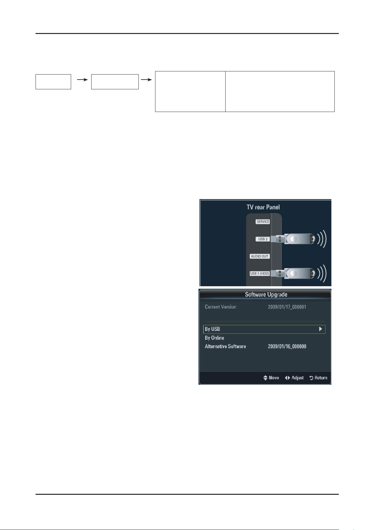
4-5-1 Upgrading the Software
Samsung may offer upgrades for TV’s rmware in the future. Please contact the Samsung call center at 1-800SAMSUNG (726-7864) to receive information about downloading upgrades and using a USB drive. Upgrades will
be possible by connecting a USB drive to the USB port located on your TV.
Insert a USB drive containing the rmware upgrade 1.
into the Wiselink Pro port on the side of the TV.
If pop up is showed, press the exit or or press the No 2.
button. (If you press Yes button, display is changed to
Wiselink Pro Menu )
Press the 3. MENU button to display the menu.
Press the ▲ or ▼ button to select "Setup", then press
the ENTER button.
Press the ▲ or ▼ button to select "SW Upgrade", then 4.
press the ENTER button.
Press the 5. ENTER button.
The message "Scanning for USB... It may take up to 30
seconds." is displayed.
The message "Upgrade version XXXX to version XXXX? 6.
The system will be reset after upgrade." is displayed.
Press the ◄ or ► to select the "OK", then press the
ENTER button.
Please be careful to not disconnect the power or remove
the USB drive while upgrades are being applied. The TV
will turn off and turn on automatically after completing
the rmware upgrade. Please check the rmware version
after the upgrades are complete. When software is
upgraded, video and audio settings you have made will
return to their default (factory) settings.
We recommend you write down your settings so that you
can easily reset them after the upgrade.
Page 59
4-52
4. Troubleshooting
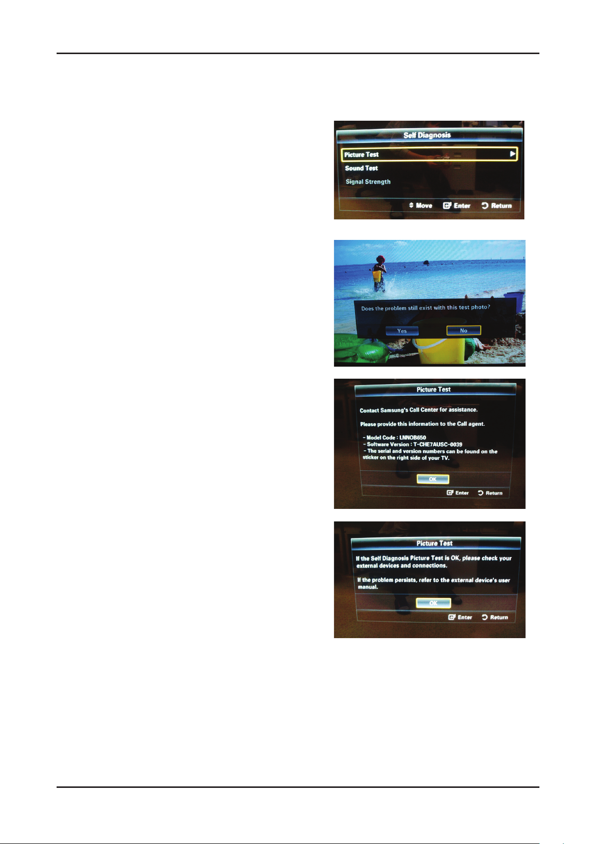
4-5-2 Self Diagnostic
This is simple test function that judge whether is TV SET’s problem or not.
There are two self-test. Picture and Sound.
Press "Menu -> Support -> Self Diagnosis" 1.
The message "Picture Test / Sound Test" is displayed.
2. Picture Test
1) The message "Does the problem still exist with this
test pattern?" is displayed.
2) Press "Yes". This is a TV SET problem.
The massage "Contact Samsung’s call center at
1-800-SAMSUNG for assistance." is displayed.
3) Press "No".
This is not a TV SET problem.
The message "If the self diagnosis picture is OK, picture
distortion may caused by your external device.
Please check connection. If the problem still persists,
refer to the external device’s user manual." is displayed.
Page 60
4-53
4. Troubleshooting
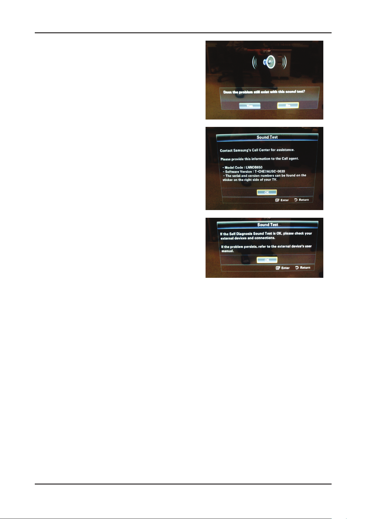
3. Sound Test
1) The message "Does the problem still exist with this
sound test?" is displayed.
2) Press "Yes". This is a TV SET problem.
The message "Contact Samsung’s call center at
1-800-SAMSUNG for assistance."is displayed
3) Press "No".
This is not a TV SET problem.
The message "If the self diagnosis picture is OK, picture
distortion may caused by your external device.
Please check connection. If the problem still persists,
refer to the external device’s user manual." is displayed.
 Loading...