

Samsung HH105EZM, HH128EZM, HH140EZM, HH175EZM, HH175ECM Service Manual
...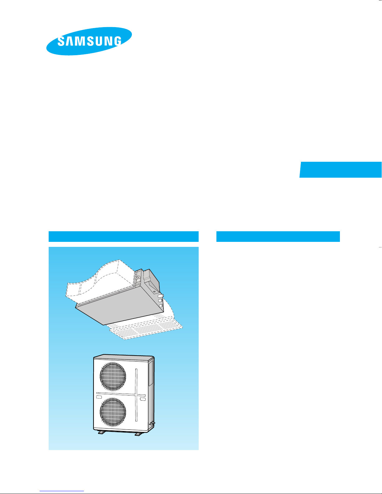
SYSTEM AIR CONDITIONER
INDOOR UNIT
HH105EZM
HH128EZM
HH140EZM
HH175EZM
HH175ECM
SERVICE
OUTDOOR UNIT
UH105GZM
UH128GZM
UH140GZM
UH175GZM
UH175GCM
Manual
CONTENTSAIR CONDITIONER
1. Product Specifications
2. Installation
3. Refrigerating Cycle Diagram
4. Set Up the Model Option
5. Troubleshooting
6. Exploded Views and Parts List
7. PCB Diagram
8. Wiring Diagram
9. Schematic Diagram
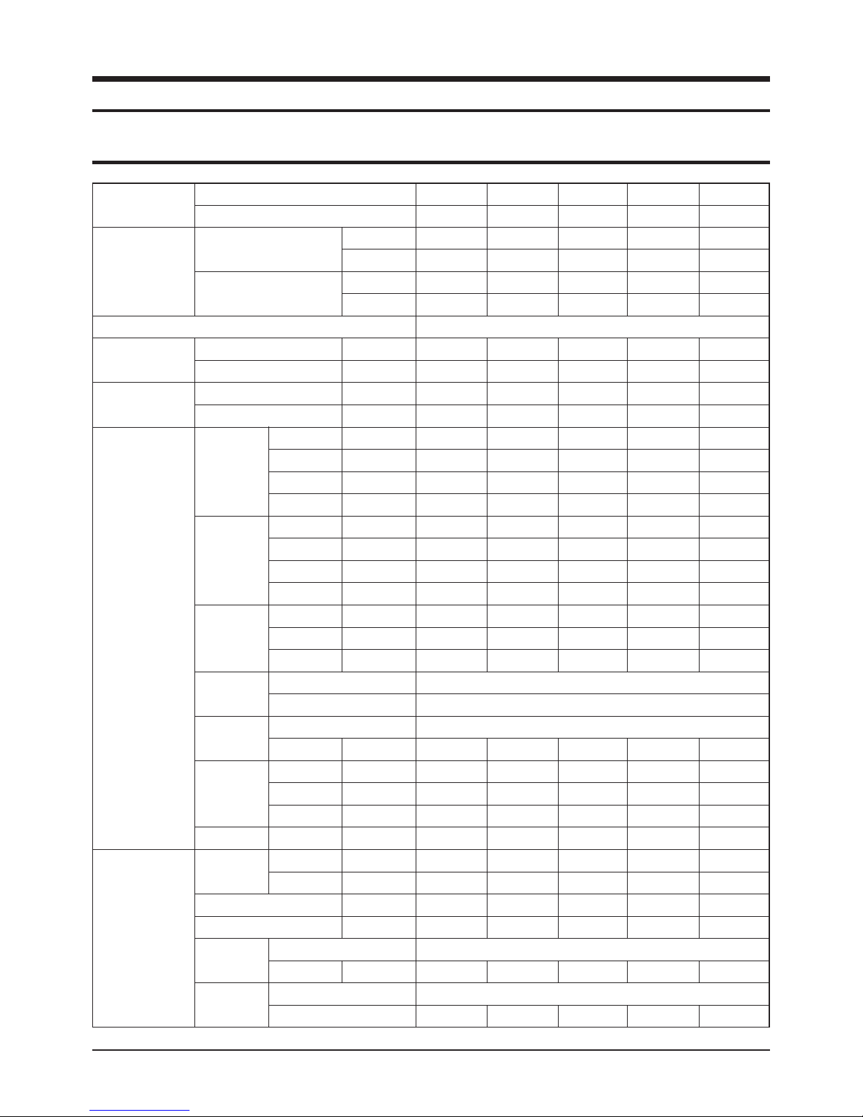
1. Product Specifications
1-1 Table
MODEL
Capacity
Power Supply
Power Input
Running Current
Indoor Unit
Outdoor Unit
INDOOR UNIT
OUTDOOR UNIT
Cooling
Heating
Cooling
Heating
Cooling
Heating
H.H
Fan Speed
(at 0mmAq)
Hi
Med
Low
H.H
Air
Circulation
(at 14mmAq)
Hi
Med
Low
Noise Level
(Sound
Pressure)
Hi
Med
Low
Heat
Exchanger
Fan
Dimensions
Weight
Fan Speed
Row x Stages x Fin Pitch
Motor Output
W
kg
Hi
Low
Air Circulation (Hi)
Sound Pressure Level
Fan
Motor Output
Compressor
HH175EZM
UH175GZM
54,600
16,000
61,400
18,000
HH175ECM
UH175GCM
56,300
16,500
64,800
19,000
Btu/h
W
Btu/h
W
HH105EZM
UH105GZM
34,000
10,000
38,200
11,200
HH128EZM
UH128GZM
43,700
12,800
47,800
14,000
HH140EZM
UH140GZM
47,800
14,000
54,600
16,000
3ø, 380-415V~, 50Hz
6.9
6.9
12.2
12.2
1,000
900
800
700
45
39
33
30
51
49
48
Type
kW
kW
A
A
r.p.m
r.p.m
r.p.m
r.p.m
3
m
/min
3
m
/min
3
m
/min
3
m
/min
dB(A)
dB(A)
dB(A)
3.45
3.0
6.1
5.35
1,000
860
760
660
35
29
23
20
48
47
46
4.45
5.25
7.9
9.3
1,050
1,000
950
900
36
34
32
30
49
48
47
5.12
5.97
10.6
12.1
1,050
1,000
950
900
36
34
32
30
49
48
47
Wave fin coil
5.7
5.6
9.6
9.4
1,000
900
800
700
45
39
33
30
51
49
48
3 x 14 x 1.7(900mm)
Type
W
H
mm
mm
D
mm
Net / Gross
r.p.m.
r.p.m.
3
m
/min
dB(A)
-
390
1,110
650
66 / 77
900
500
-
65
211
390
1,110
650
66 / 77
900
500
-
65
Type
W
-
114
Type
Model
ZR45KC-TFD
ZR61KC-TFD
Sirocco
211
390
1,110
650
66 / 77
900
450
90
65
Propeller
114
Scroll
ZR61KC-TFD
-
390
1,400
650
75 / 88
900
500
90
65
114
ZR72KC-TFD
-
390
1,400
650
75 / 88
930
450
90
67
114
ZR81KCE-TFD
1Samsung Electronics
Table(cont.)
MODEL
Outdoor Unit
Condition
Piping
INDOOR UNIT
OUTDOOR UNIT
Compressor
Heat
Exchanger
Refrigerant
Dimensions
Weight
Indoor Unit
Outdoor Unit
Pipe O.D.
Size
Connection Method
Between
Capacity
Row x Stages x Fin Pitch
Face Area
(R22)Charge
(H x W x D)
Cool(DB/WB)
Heat(DB/WB)
Cool(DB/WB)
Heat(DB/WB)
Pipe Length
kg
Liquid
Gas
Height
Protection
Type
Control
Net / Gross
kW
2
m
g
mm
˚C
˚C
˚C
˚C
mm(inch)
mm(inch)
m
m
HH105EZM
UH105GZM
11. 1
0.756
2,200
968 x 880 x 320
85 / 90
HH128EZM
UH128GZM
14.6
1.122
4,300
130 / 140
HH140EZM
UH140GZM
Wave fin coil
2 x 48 x 1.7(935 / 915)
Electrical expansion valve
19.05(3/4")
14.6
Internal
1.122
4,300
1,270 x 930 x 385
130 / 140
27 / 19
20 / 15
35 / 24
7 / 6
9.52(3/8")
Flare
Max. 30
Max. 50
HH175EZM
UH175GZM
17.7
1.122
3,750
136 / 146
HH175ECM
UH175GCM
19.7
1.122
3,850
136 / 146
Notice : This model is tested under the external static pressure of 14mmAq.
Samsung Electronics2

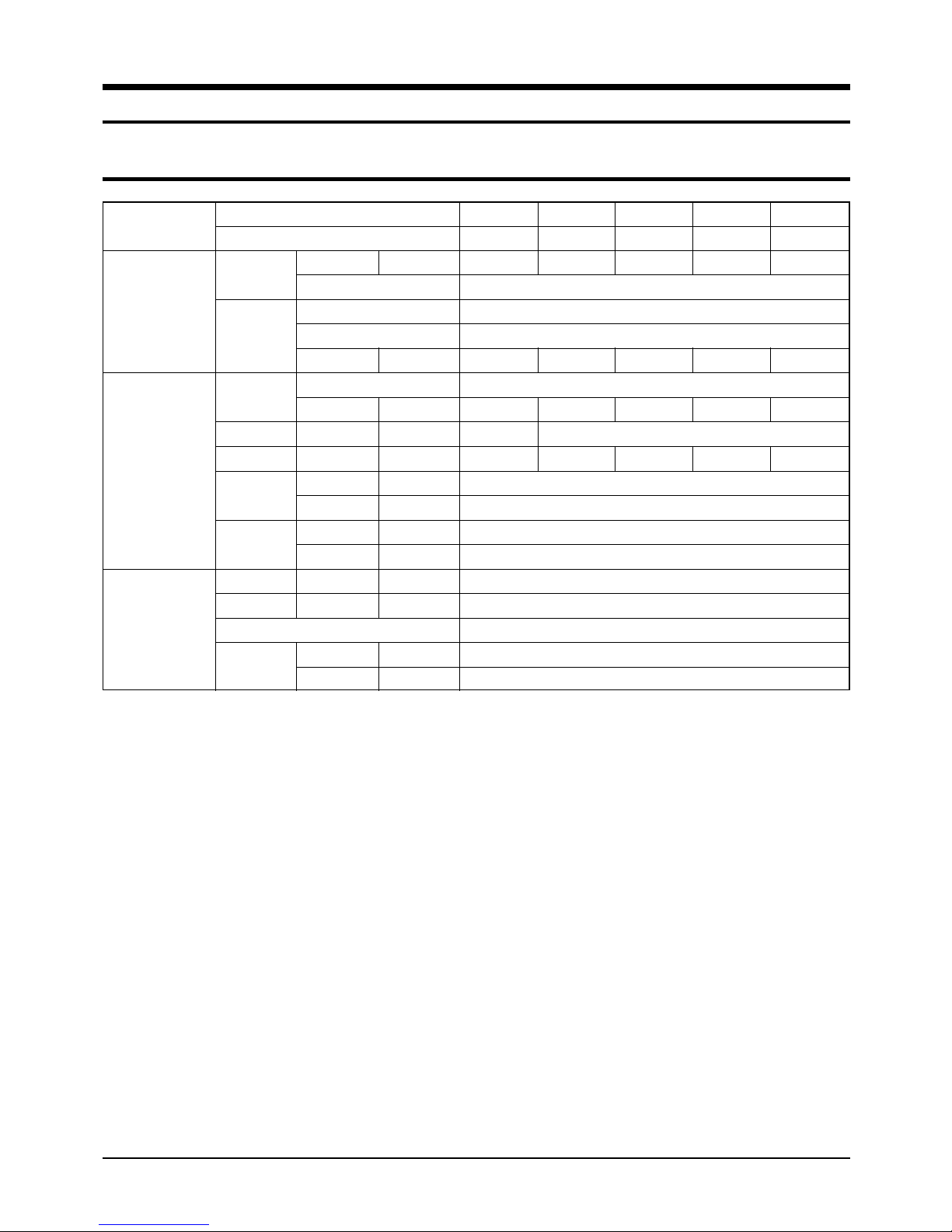
■ This Spec. is for Australia
MODEL
Capacity
Power Supply
Power Input
Running Current
Indoor Unit
Outdoor Unit
INDOOR UNIT
OUTDOOR UNIT
Cooling
Heating
Cooling
Heating
Cooling
Heating
Fan Speed
(at 0mmAq)
Air
Circulation
(at 14mmAq)
Noise Level
(Sound Pressure)
Heat
Exchanger
Fan
Dimensions
Weight
Fan Speed
Air Circulation (Hi)
Sound Pressure Level
Fan
Compressor
Btu/h
Btu/h
H.H
Hi
Med
Low
H.H
Hi
Med
Low
Hi
Med
Low
r.p.m
r.p.m
r.p.m
r.p.m
m
m
m
m
dB(A)
dB(A)
dB(A)
Type
Row x Stages x Fin Pitch
Type
Motor Output
H
W
D
kg
Hi
Low
Net / Gross
r.p.m.
r.p.m.
m
dB(A)
Type
Motor Output
Type
Model
W
W
kW
kW
A
A
3
/min
3
/min
3
/min
3
/min
W
mm
mm
mm
3
/min
W
HH175EZM
UH175GZM
49,500
14,500
61,400
18,000
3ø, 380-415V~, 50Hz
5.8
5.75
9.1
9.4
1,000
900
800
700
45
39
33
30
51
49
48
Wave fin coil
3 x 14 x 1.7(900mm)
Sirocco
-
390
1,400
650
75 / 88
900
500
90
65
Propeller
114
Scroll
ZR72KC-TFD
3Samsung Electronics
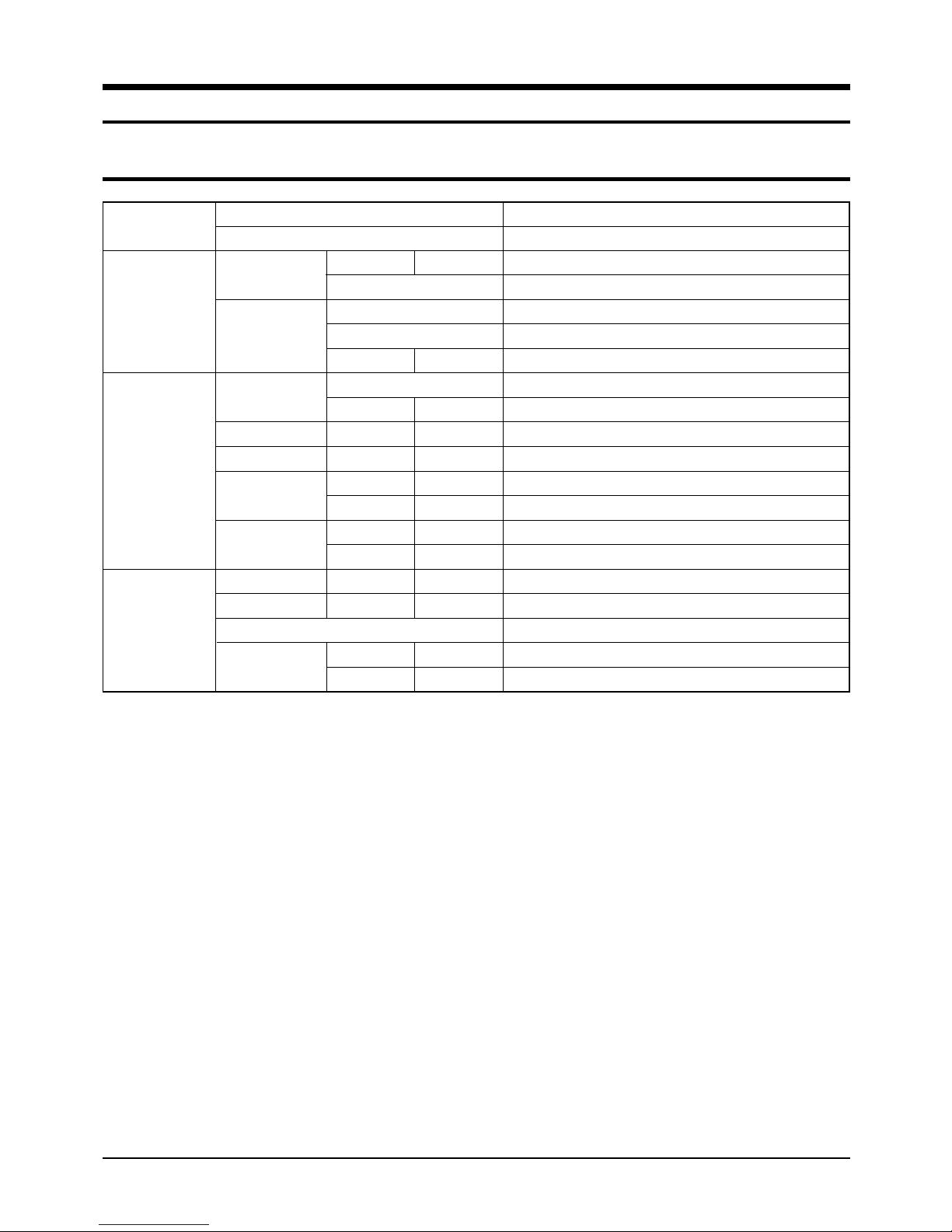
■ This Spec. is for Australia(cont.)
MODEL
Compressor
Outdoor Unit
Heat Exchanger
Refrigerant
Dimensions
Condition
Piping
Notice : This model is tested under the external static pressure of 14mmAq.
Weight
Indoor Unit
Outdoor Unit
Pipe O.D.
Size
Connection Method
Between
INDOOR UNIT
OUTDOOR UNIT
Capacity
Protection
Type
Row x Stages x Fin Pitch
Face Area
Control
(R22)Charge
(H x W x D)
kg
Cool(DB/WB)
Heat(DB/WB)
Cool(DB/WB)
Heat(DB/WB)
Liquid
Gas
Height
Pipe Length
kW
2
m
g
mm
Net / Gross
˚C
˚C
˚C
˚C
mm(inch)
mm(inch)
m
m
HH175EZM
UH175GZM
17.7
Internal
Wave fin coil
2 x 48 x 1.7(935 / 915)
1.122
Electrical expansion valve
3,750
1,270 x 930 x 385
136 / 146
27 / 19
20 / 15
35 / 24
7 / 6
9.52(3/8")
19.05(3/4")
Flare
Max. 30
Max. 50
Samsung Electronics4
1-2 Dimensions
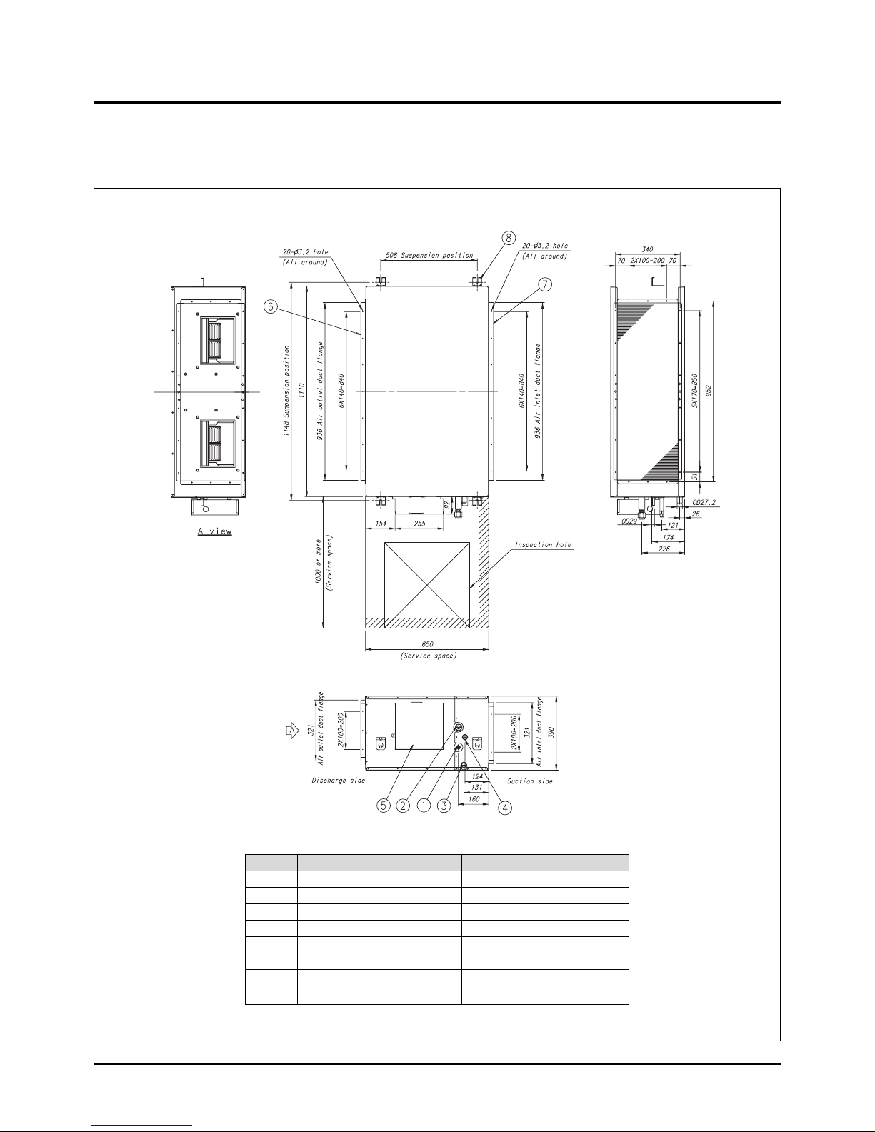
1-2-1 Indoor Unit
■ HH105EZM / HH128EZM/ HH140EZM
(Unit : mm)
Number
1
2
3
4
5
6
7
8
Name
Liquid pipe connection
Gas pipe connection
Drain pipe connection
Drain pipe connection
Power supply connection
Air discharge flange
Air suction flange
Hook
Description
ø9.52 Flare
ø19.05 Flare
OD27.2 ID21.6 (without drain pump)
OD29 ID25 (with drain pump)
For M8~M10
5Samsung Electronics
Product Specifications
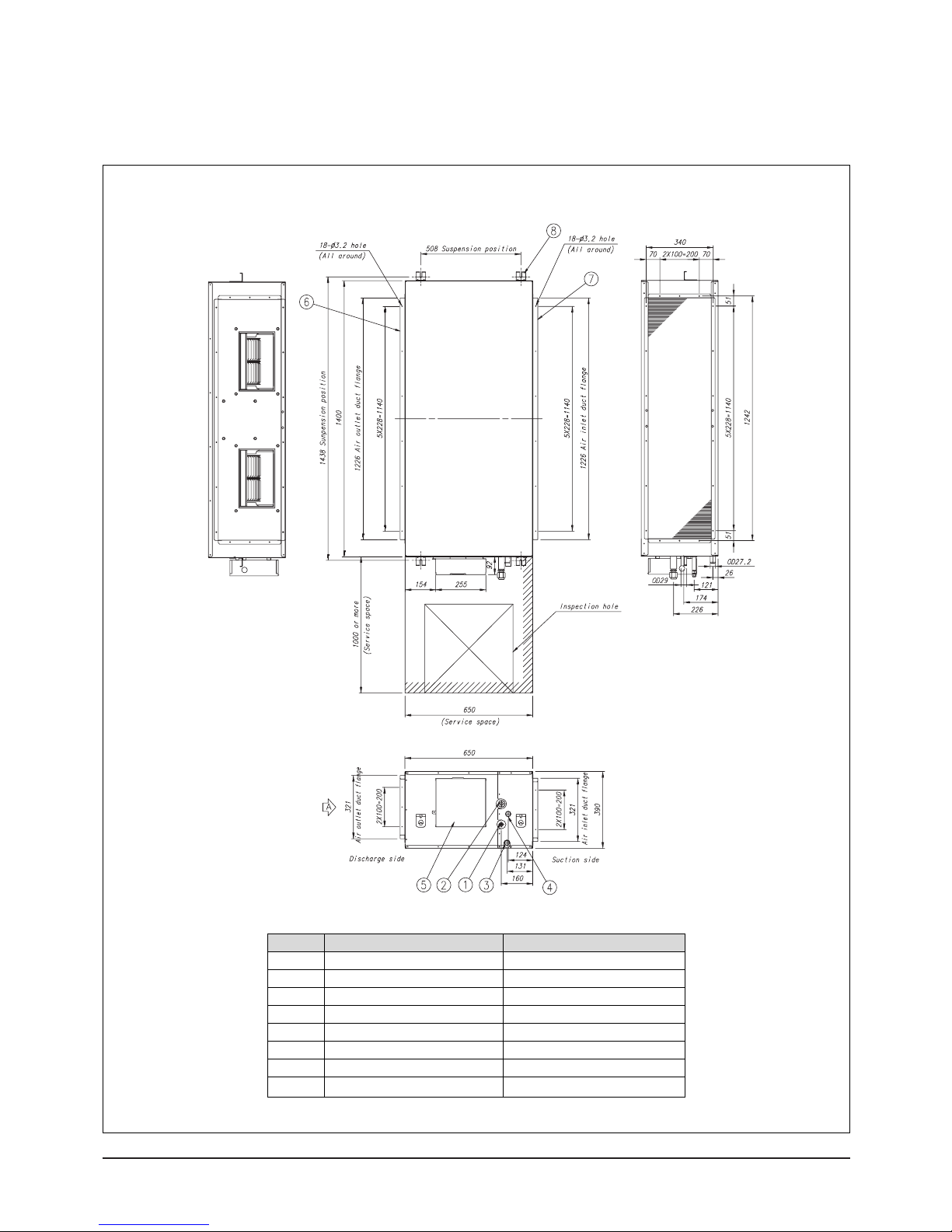
■ HH175EZM /HH175ECM
(Unit : mm)
Number
1
2
3
4
5
6
7
8
Name
Liquid pipe connection
Gas pipe connection
Drain pipe connection
Drain pipe connection
Power supply connection
Air discharge flange
Air suction flange
Hook
Description
ø9.52 Flare
ø19.05 Flare
OD27.2 ID21.6 (without drain pump)
OD29 ID25 (with drain pump)
For M8~M10
Samsung Electronics6
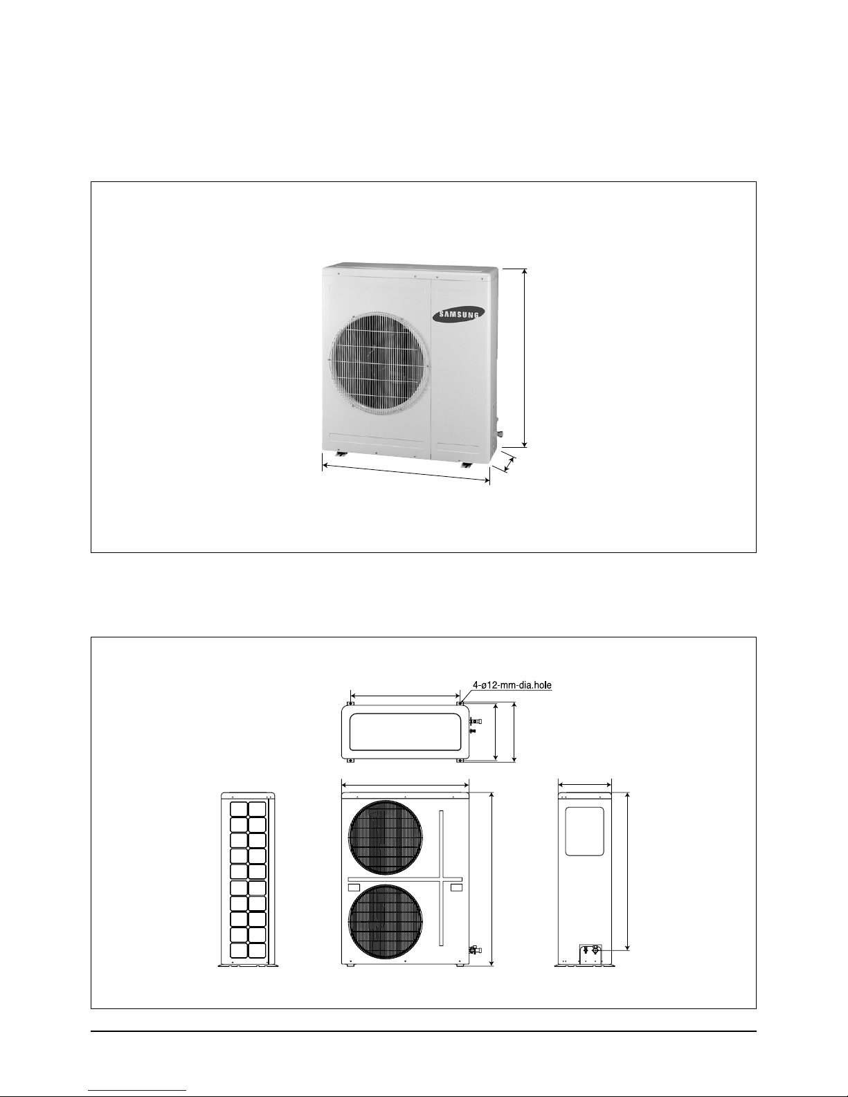
1-2-2 Outdoor Unit
320
880
968
800
932
415
440
385
1,270
1,154
■ UH105GZM
Product Specifications
(Unit : mm)
■ UH128GZM / UH140GZM/ UH175GZM /UH175GCM
(Unit : mm)
7Samsung Electronics
2. Installation
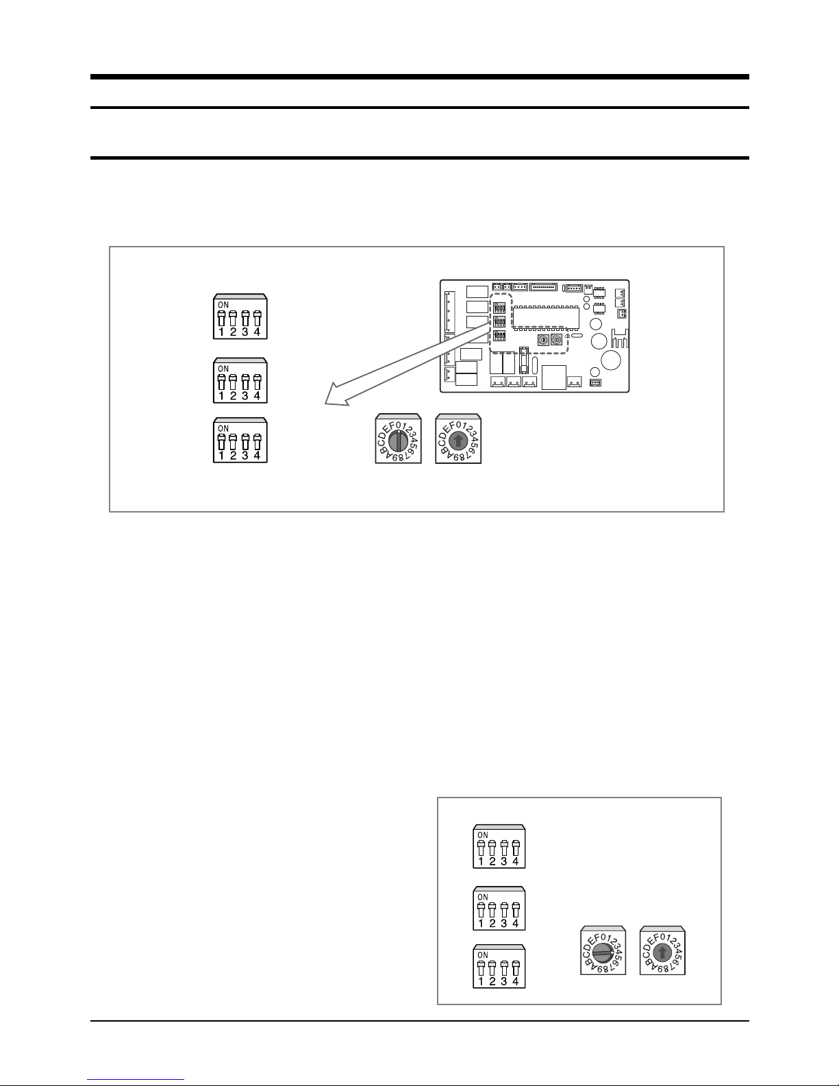
2-1 Assigning Address to Indoor Unit
1. Before installing the indoor unit, assign an address to the indoor unit according to the air conditioning system plan.
2. The address of the indoor unit is assigned by adjusting MAIN(SW02) and RMC(SW01) rotary switches.
K1 K2 K3 K4
SW03
K5 K6 K7 K8
SW04
K10
K11
K12
K9
SW05
SW02 MAIN SW01 RMC
3. The MAIN address is for communication between the indoor unit and the outdoor unit.
Therefore, you must set it to operate the air conditioner properly.
4. It is required to set the RMC address if you install the wired remote controller and/or the centralized controller.
5. If you install optional accessories such as the wired remote controller, centralized controller, etc. see an appropriate
installation manual.
6. If an optional accessory is not installed, you do not have to set the RMC address. However, adjust K1 and K2 switches of
the SW03 DIP switch to "ON" position in this case.
7. Set the MAIN address by adjusting the rotary switch(SW02) from 0 to F. Each indoor unit connected to the same outdoor
unit must have different address.
7.
i. e. If an indoor unit does not have an optional accessory and its
MAIN address is "4".
K1 K2 K3 K4
K5 K6 K7 K8
K9
K10
K11
K12
SW03
SW04
SW05
SW02 MAIN
SW01 RMC
Samsung Electronics8
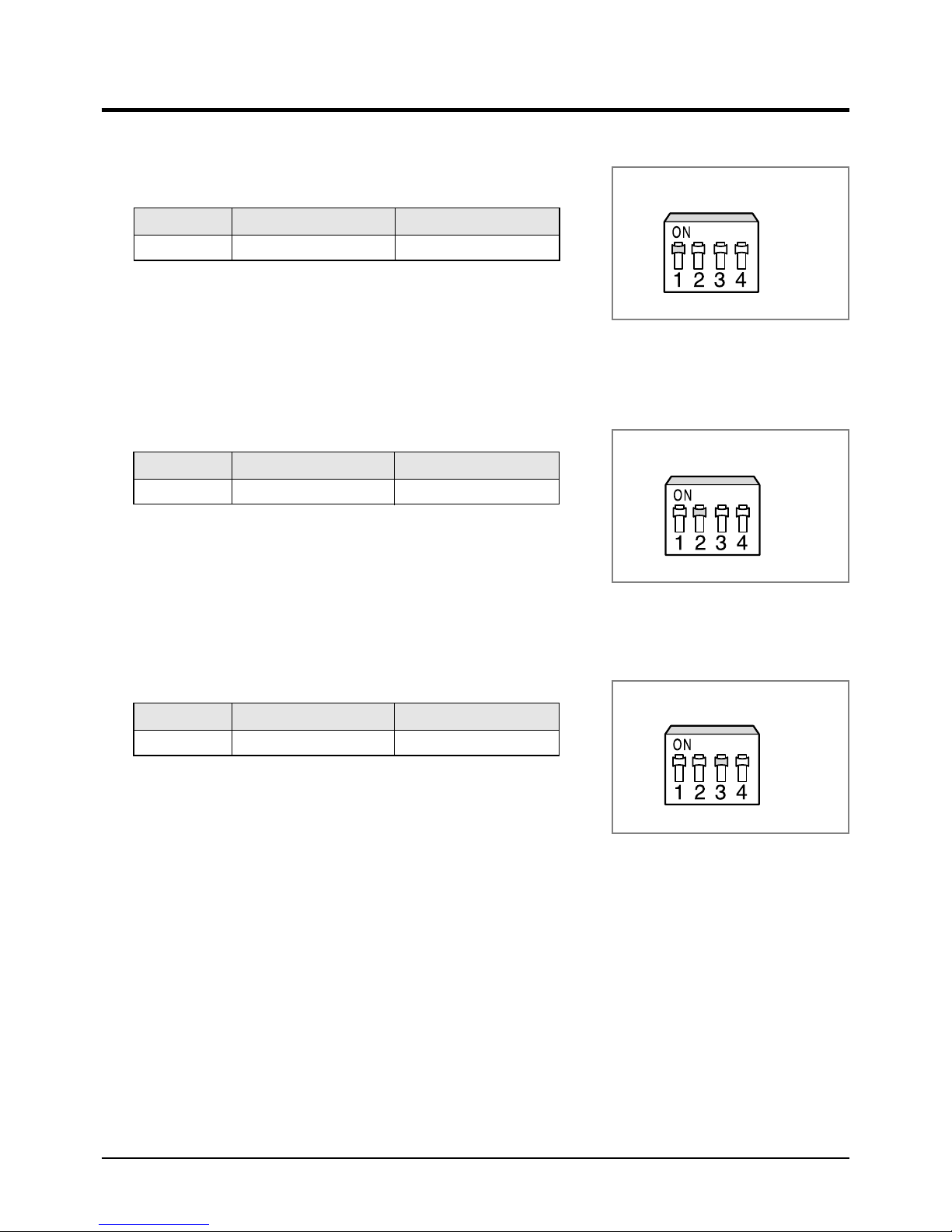
2-2 Additional Functions
K5 K6 K7 K8
K5 K6 K7 K8
K5 K6 K7 K8
■ Compensation for lost temperature in heating operation
■
• Reduces the difference between an actual room temperature and a sensed
■
• temperature by the air conditioner when heating.
Switch No. Switch ON Switch OFF
K5 2°C compensation 5°C compensation
■ Adjusting filter cleaning cycle
■
• You can adjust the cycle for filter sign indicator.
Switch No. Switch ON Switch OFF
K6 1000 hours 2000 hours
■ Hot water heater
■
• You must adjust the K7 when you install the hot water heater.
SW04
SW04
Switch No. Switch ON Switch OFF
K7 No use of hot water heater Use of hot water heater
SW04
9Samsung Electronics
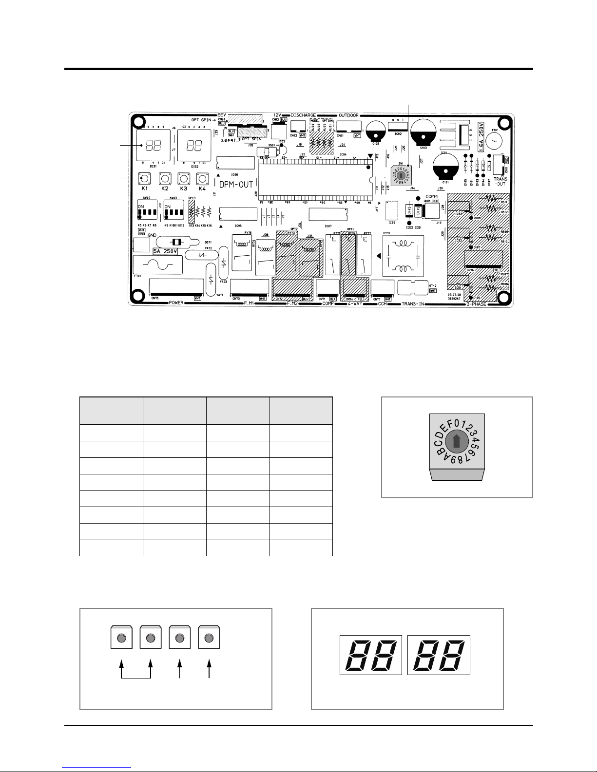
2-3 Setting Up Option Switches
■ Option Switch
Display
Key
■ Rotary Switch
■
You should display that how many indoor units are connected to the
outdoor unit. Refer to the table below, then turn the arrow to appropriate
position.
Rotary Switch
Switch No.
0 or 1
2
3
4
5
6
7
8
Number of
indoor unit(s)
One
Two
Three
Four
Five
Six
Seven
Eight
Switch No.
9
A
B
C
D
E
F
-
Number of
indoor unit(s)
Nine
Te n
Eleven
Twelve
Thirteen
Fourteen
Fifteen
-
■ KEY ■ Display
K1 K2 K3 K4
RESETCHECK MODE DISPLAY
MODE
DIS 1
SEG 1 SEG 2 SEG 3 SEG 4
DIS 2
Samsung Electronics10
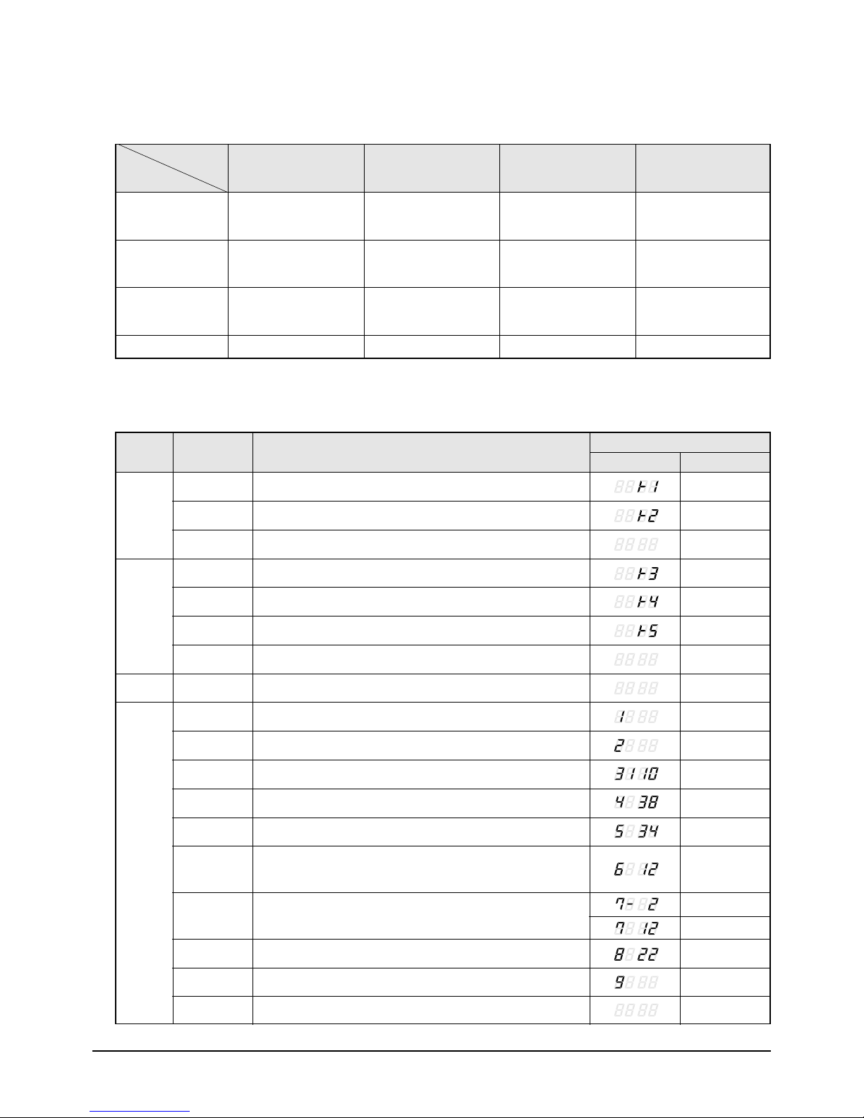
■ Summary of KEY functions
Installation
Number
of press times
✳ Use the K1 only for heat pump models.
Function
(Displayed on SEG 3, 4)
1
2
3
4
K1
Adding refrigerant at
heating mode
Test operation at
heating mode
End
-
■ Reading data indicated on the display
KEY
K1
Number of
press
1
2
3
Adding refrigerant for heat pump models
Test operation for heat pump models
End
(Displayed on SEG 3, 4)
K2
Adding refrigerant at
cooling mode
Test operation at
cooling mode
Pump Down for recovery
of refrigerant
End
Item
(Displayed on SEG 3, 4)
K3
Reset
-
-
-
Display Meaning
(Displayed on SEG 3, 4)
K4
Displays data
-
-
-
Example
K2
K3
K4
1
2
3
4
1
2
3(1)
4(2)
5(3)
6(4)
7(5)
8(6)
Adding refrigerant for cooling only models
Test operation for cooling only models
Pump Down for recovery of refrigerant
End
Reset
Discharge temperature of compressor
Temperature of outdoor heat exchanger
Outdoor temperature
Step of electronic expansion valve
(0 step : all closed, 480 step : all open)
Temperature of evaporator
Indoor temperature
110 °C
38 °C
34 °C
120STEP
(12 x 10)
-2 °C
12 °C
22 °C
9
10(7)
✳ ( ) is adjusted to HH105EZM/HH128EZM/HH140EZM models.
Stopping view mode & display communication data
11Samsung Electronics
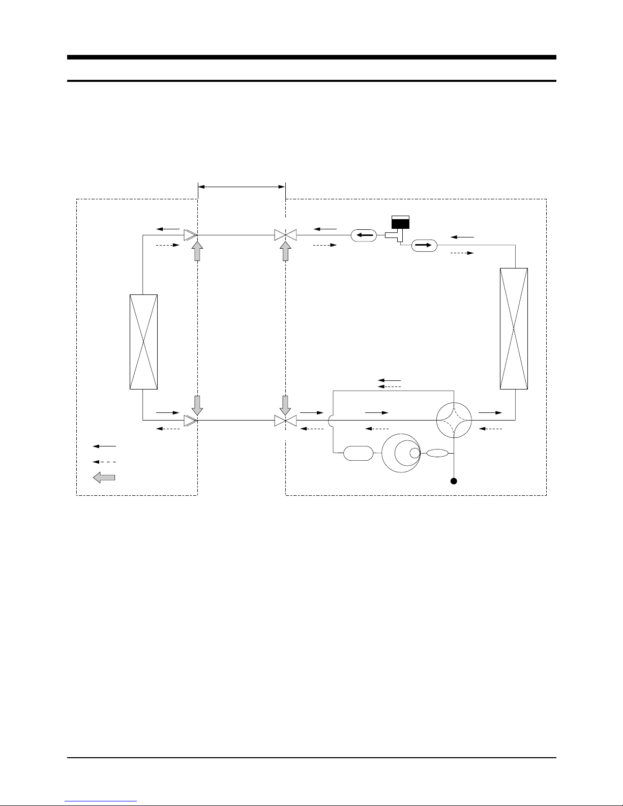
3. Refrigerating Cycle Diagram
Liquid Side
*Allowable pipe length : Max. 50m
*Allowable drop distance : Max. 30m
Gas Side
INDOOR UNIT OUTDOOR UNIT
Heat
Exchanger
(Evaporator)
Heat
Exchanger
(Condensor)
Muffler
Compressor
High pressure switch
Accumulator
Cooling
Heating
Gas leak check point
3-Way Valve
Filter
Filter
EEV
3-Way Valve
Samsung Electronics12
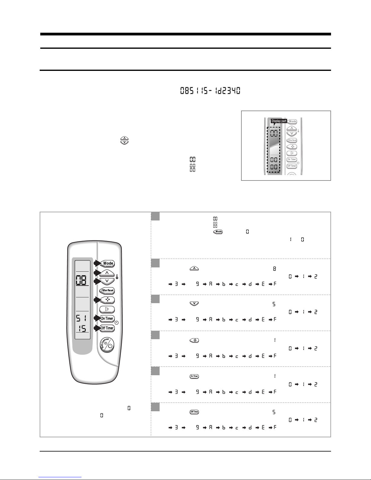
4. Set Up the Model Option
4-1 Setting Option Setup Method
ex) Option No. :
Step 1 : Enter the Option Setup mode.
st
1
Take out the batteries of remote control.
nd
2
Press the temp. button simultaneously and
insert the battery again.
rd
3
Make sure the remote control display shown as .
Step 2 : Enter the Option Setup mode and select your option according to the following procedure.
1
The default value is .
Otherwise, push the button to .
Every time you push the button, the display panel reads or
repeatedly.
1
2
3
4
5
6
2
Push the button to set the display panel to .
Every time you push the button, the display panel reads
. . .
3
Push the button to set the display panel to .
Every time you push the button, the display panel reads
. . .
repeatedly.
repeatedly.
4
Push the button to set the display panel to .
Every time you push the button, the display panel reads
. . .
repeatedly.
✳ Setting is not required if you must
a value which has a default.
5
Push the button to set the display panel to .
Every time you push the button, the display panel reads
. . .
6
Push the button to set the display panel to .
Every time you push the button, the display panel reads
. . .
repeatedly.
repeatedly.
13Samsung Electronics
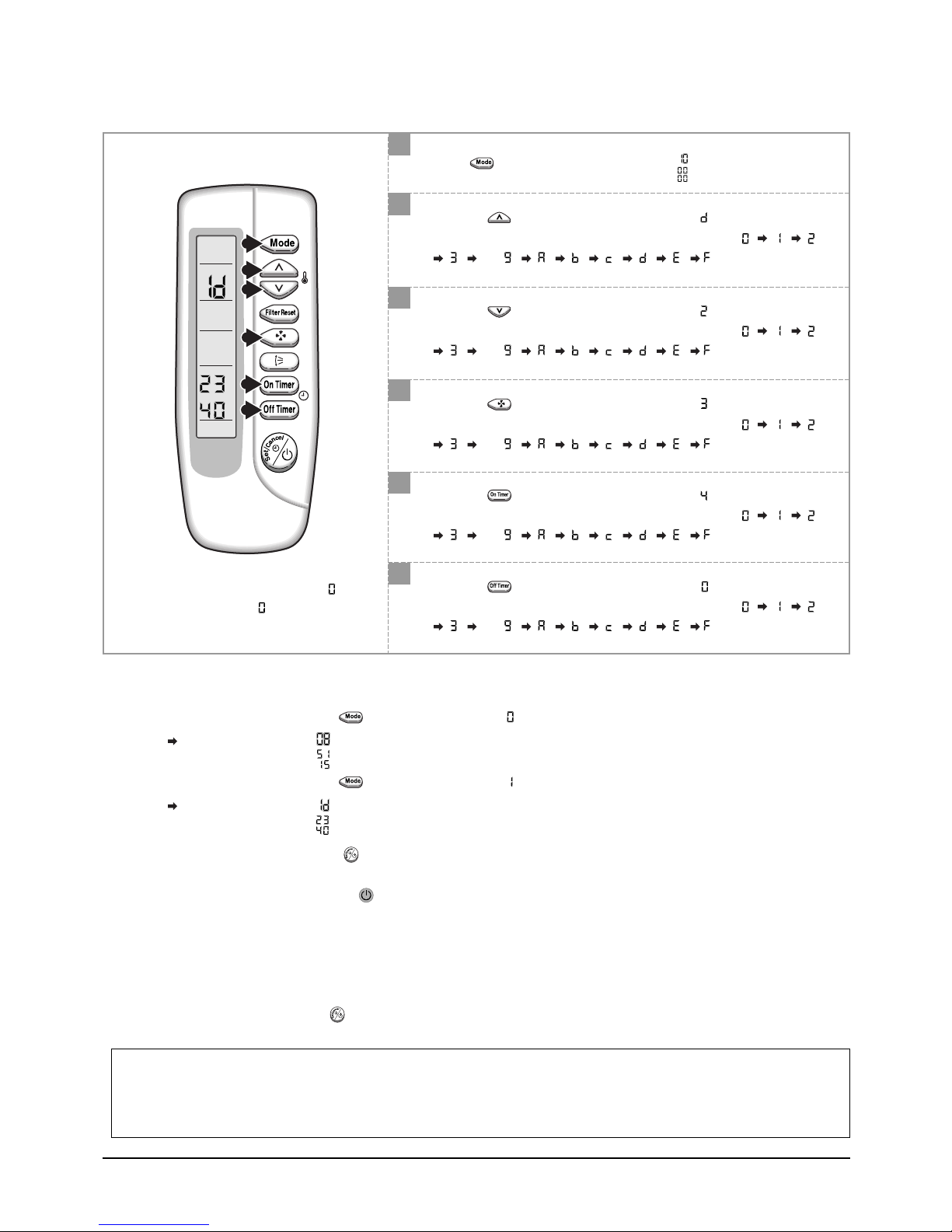
Set Up the Model Option
7
Press button, then the default value is .
8
Push the button to set the display panel to .
7
8
9
10
Every time you push the button, the display panel reads
. . .
9
Push the button to set the display panel to .
Every time you push the button, the display panel reads
. . .
repeatedly.
repeatedly.
11
12
✳ Setting is not required if you must
a value which has a default.
10
Push the button to set the display panel to .
Every time you push the button, the display panel reads
. . .
11
Push the button to set the display panel to .
Every time you push the button, the display panel reads
. . .
12
Push the button to set the display panel to .
Every time you push the button, the display panel reads
. . .
Step 3 : Upon completion of the selection, check you made right selections.
Press the Mode Selection key, to set the display part to and check the display part.
The display part shows .
Press the Mode Selection key, to set the display part to and check the display part.
The display part shows .
repeatedly.
repeatedly.
repeatedly.
Step 4 : Pressing the ON/OFF button ( )
When pressing the operation ON/OFF key with the direction of remote control for unit, the sound ''Ding'' or ''Diriring'' is
heard and the OPERATION ICON( ) lamp of the display is flickering at the same time, then the input of option is completed. (If the diriring sound isn't heard, try again pressing the ON/OFF button.)
Step 5 : Unit operation test-run
First, Remove the battery from the remote control.
Second, Re-insert the battery into the remote control.
Third, Press ON/OFF button( ) with the direction of remote control for set.
• Error Mode
1stIf all lamps of indoor unit are flickering, Plug out, plug in power plug again and press ON/OFF key to retry.
2ndIf the unit is not working properly or all lamps are continuously flickering after setting the option code, see if the correct option code is
set up for its model.
Samsung Electronics14
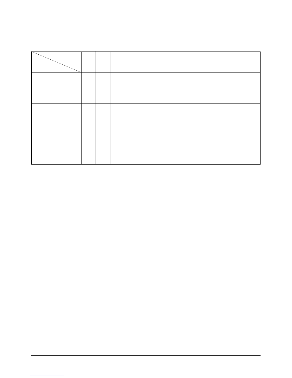
■ OPTION ITEMS
REMOTE
CONTROL
MODEL
Set Up the Model Option
SEG1 SEG2 SEG3 SEG4 SEG5 SEG6 SEG7 SEG8 SEG9 SEG10 SEG11 SEG12
HH105EZM
HH128EZM
HH140EZM
HH175EZM
HH175ECM
0154421F0000
015800130000
015800140000
15Samsung Electronics
5. Troubleshooting
■ Detection of errors
● If an error occurs during the operation, an LED flickers and the operation is stopped except the LED.
● If you re-operate the air conditioner, it operates normally at first, then detect an error again.
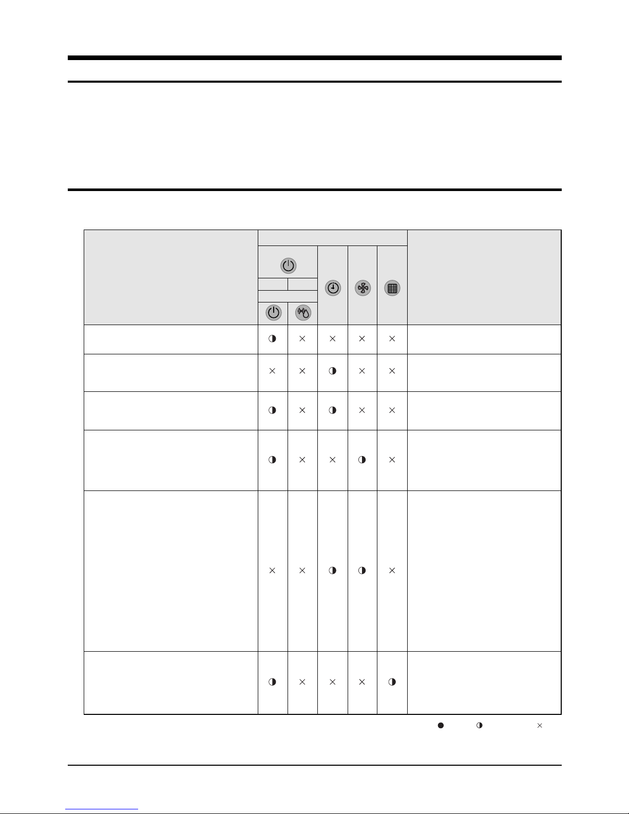
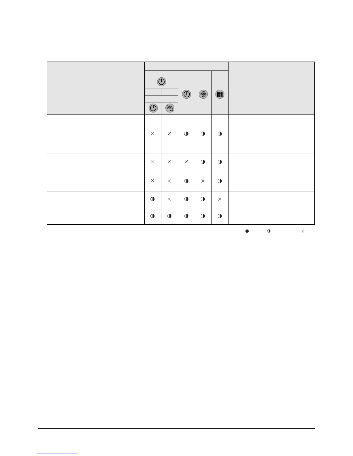
5-1 LED Display on the receiver & display unit
■ LED Display
Indicators
Concealed Type
Abnormal conditions
Power reset
Error of temperature sensor in indoor unit
(OPEN/SHORT)
Error of heat exchanger sensor in indoor
unit(OPEN/SHORT)
Error of outdoor temperature sensor
Error of COND sensor
Error of DISCHARGE sensor
(OPEN/SHORT)
1. No communication for 2 minutes between
indoor unit and outdoor unit
(communication error for more than
2 minutes)
2. Indoor unit receiving the communication
error from outdoor unit
3. Outdoor unit tracking 3 minute error
4. When sending the communication error from
outdoor unit the mismatching of the
communication numbers and installed
numbers after completion of tracking. (communication error for more than 2 minutes)
Blue
Red
Standard Type
Operating
Displayed on appropriate indoor unit
which is operating
Displayed on appropriate indoor unit
which is operating
Displayed on appropriate indoor unit
which is operating
Displayed on outdoor unit
1. Error of indoor unit: Displayed on
the indoor unit regardless of
operation
2. Error of outdoor unit: Displayed on
the indoor unit which is operating
1. Communication error between indoors
(Communication error for more than
2 minutes)
2. Slave of indoor unit tracking error
-
If you turn off the air conditioner when the LED is flickering, the LED is also turned off. : On : Flickering : Off
-
If you re-operate the air conditioner, it operates normally at first, then detect an error again.
Error of indoor unit: Displayed on the
indoor unit regardless of operation
Samsung Electronics16
■ LED Display(cont.)
Toubleshooting
Indicators
Concealed Type
Abnormal conditions
Blue
Red
Operating
Standard Type
1. 2nd detection of high temperature COND
2. 2nd detection of high temperature
DISCHARGE
Displayed on appropriate indoor
unit which is operating
Displayed on outdoor unit
3. Error of reverse phase
Error of float switch
Error of setting option switches for optional
accessories
EEPROM error
EEPROM option error
-
If you turn off the air conditioner when the LED is flickering, the LED is also turned off. : On : Flickering : Off
-
If you re-operate the air conditioner, it operates normally at first, then detect an error again.
17Samsung Electronics
 Loading...