

Samsung DH094EAM, UH094EAMC Service Manual

DUCT TYPE AIR CONDITIONER
INDOOR UNIT
DH094EAM
SERVICE
OUTDOOR UNIT
UH094EAMC
Manual
CONTENTSAIR CONDITIONER
1. Product Specifications
2. Disassembly and Reassembly
3. Refrigerating Cycle Diagram
4. Set Up the Model Option
5. Control Specification &
5. Troubleshooting
6. Exploded Views and Parts List
7. Block Diagram
8. Wiring Diagram
9. Schematic Diagram

1. Product Specifications
1-1 Table
MODEL
Capacity
Power Input
Running
Current
Indoor Unit
Outdoor Unit
INDOOR UNIT
OUTDOOR UNIT
Cooling
Heating
Power Supply
Cooling W
Heating W
Cooling A
Heating A
H.H r.p.m
Fan Speed
Air Flow
Noise Level(Hi)
(Sound Pressure)
Heat Exchanger
Fan
Dimensions W mm
Weight Net / Gross kg
Fan Speed
Air Flow(Hi)
Noise Level
(Sound Pressure)
Fan
Compressor
Hi r.p.m
Mid r.p.m
Low r.p.m
H.H m
Hi m
Mid m3/min
Low m
Cooling(Hi) dB(A)
Heating(Hi) dB(A)
Type
Row x Stages x Fin pitch
Type
Motor Output W
Hmm
Dmm
Hi r.p.m
Low r.p.m
Cooling(Hi) dB(A)
Heating(Hi) dB(A)
Type
Motor Output W
Type
Model
Motor Output kW
Protection
BTU/h
W
BTU/h
W
ø/V/Hz
3
/min
3
/min
3
/min
3
m
/min
DH094EAM
UH094EAMC
32,000
9,400
34,800
10,200
1/220~240/50
3,550
3,300
15.9
15.2
1,170
1,020
870
720
27
23
20
16
42
42
Slit
3 x 12 x 1.5mm
Sirocco
157
260
1,340
600
43 / 51
930
360
67
63
64
Propeller
122
Rotary
NN40VAAMT
2.7
Internal
1Samsung Electronics

Table(cont.)
MODEL
Outdoor Unit
Piping
INDOOR UNIT
OUTDOOR UNIT
Type
Refrigerant
Heat Exchanger
Dimensions W mm
Weight Net / Gross kg
Pipe O.D Size
Connection Method
Between
Charge g
Adding Charge g / m
Control
Type
Row x Stages x Fin pitch
H mm
Dmm
Liquid mm(inch)
Gas mm(inch)
Height m
Pipe Length m
DH094EAM
UH094EAMC
R410A
1,750
60
Elec.Expansion Valve
Louver
2 x 36 x 1.5
798
880
310
74 / 82
9.52(3/8")
15.88(5/8")
Flare
Max.15
Max.30
Samsung Electronics2
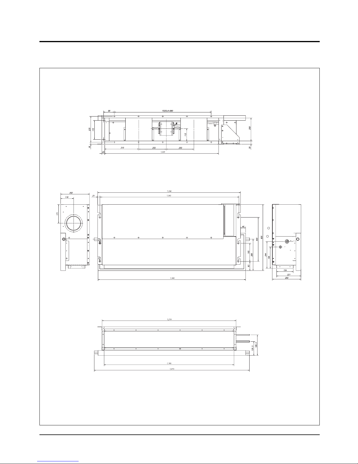
1-2 Dimensions
1-2-1 Indoor Unit
(Unit : mm)
3Samsung Electronics

Product Specifications
1-2-2 Outdoor Unit
(Unit : mm)
798
880
310
Samsung Electronics4
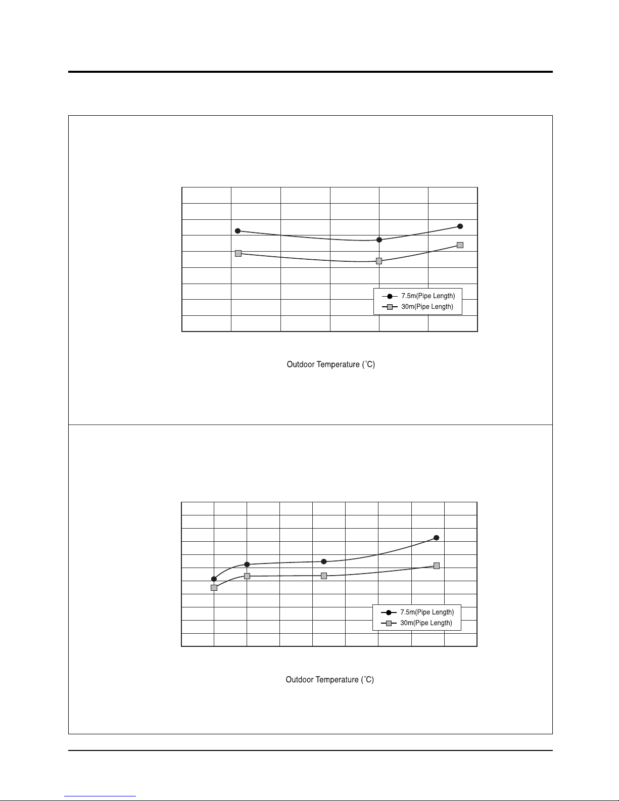
1-3 Pressure Graph
■ DH094EAM/ UH094EAMC
10.0
9.5
9.0
G)
2
8.5
8.0
7.5
7.0
6.5
Low Pressure (kgf/cm
6.0
5.5
15 20 25 30 35 40 45
Cooling Mode
37.0
35.0
33.0
G)
2
31.0
29.0
27.0
25.0
23.0
21.0
High Pressure (kgf/cm
19.0
17.0
15.0
-15 -10 -5 0 5 10 15 20 25 30
Heating Mode
5Samsung Electronics
2. Disassembly and Reassembly
Stop operation of the air conditioner and remove the power cord before repairing the unit.
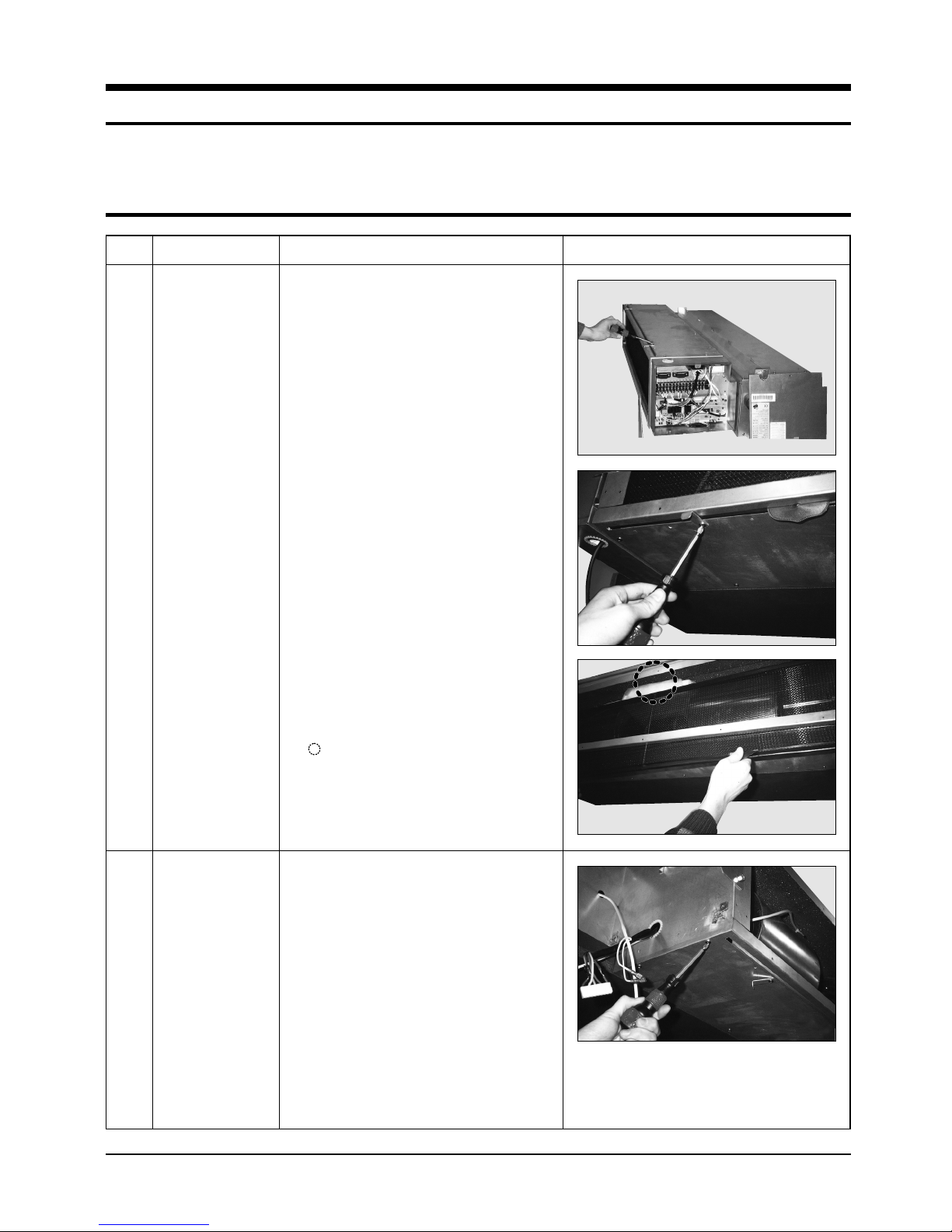
2-1 Indoor Unit
No Parts Procedure Remark
1
Filter-Pre
1) Disassemble 2 screws of indication part
and then assemble the direction of
2 Plate-Handle places by use of screw
as shown in 2).
2) Turn the Plate Handle by hand when
removing the Filter-Pre.
3) When pulling the Filter-Pre handle,
the Filter-Pre can be assembled.
✳ Be sure to remove the cushion on the
marked part after initial installation.
(It cause the damage of noise).
2
Blower & Duct
1) After disassembling 9 places indicating
screws, detach Ass'y Cover Bottom.
Samsung Electronics6
Disassembly and Reassembly
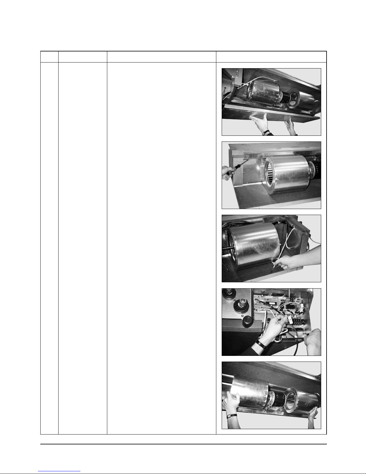
No Parts Procedure Remark
2) Disassemble 6 indicating screws.
3) Detach the Sensor Holder from the
Ass'y Fan Case.
4) Detach from Ass'y Control In the
capacitor connection wire between the
Motor-Fan in and housing Connector.
5) Detach the Ass'y Blower and Duct from
the set.
7Samsung Electronics
Disassembly and Reassembly
No Parts Procedure Remark
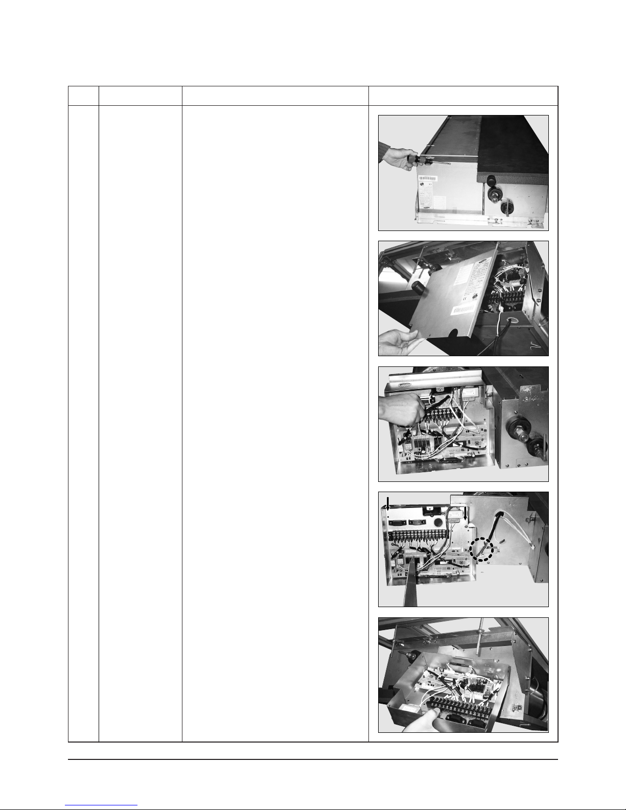
3 Control In
1) After disassembling 1 indicating screw,
detach the Cover-Control.
2) Detach the Motor-Fan in and Sensor
Connector connected to PCB.
3) Disassemble 2 indicating screws.
(arrow mark)
4) Hold the Ass'y Control In by hand to lift up
a little and then release the status of
hanging on the hanging slot.
Samsung Electronics8

Disassembly and Reassembly
No Parts Procedure Remark
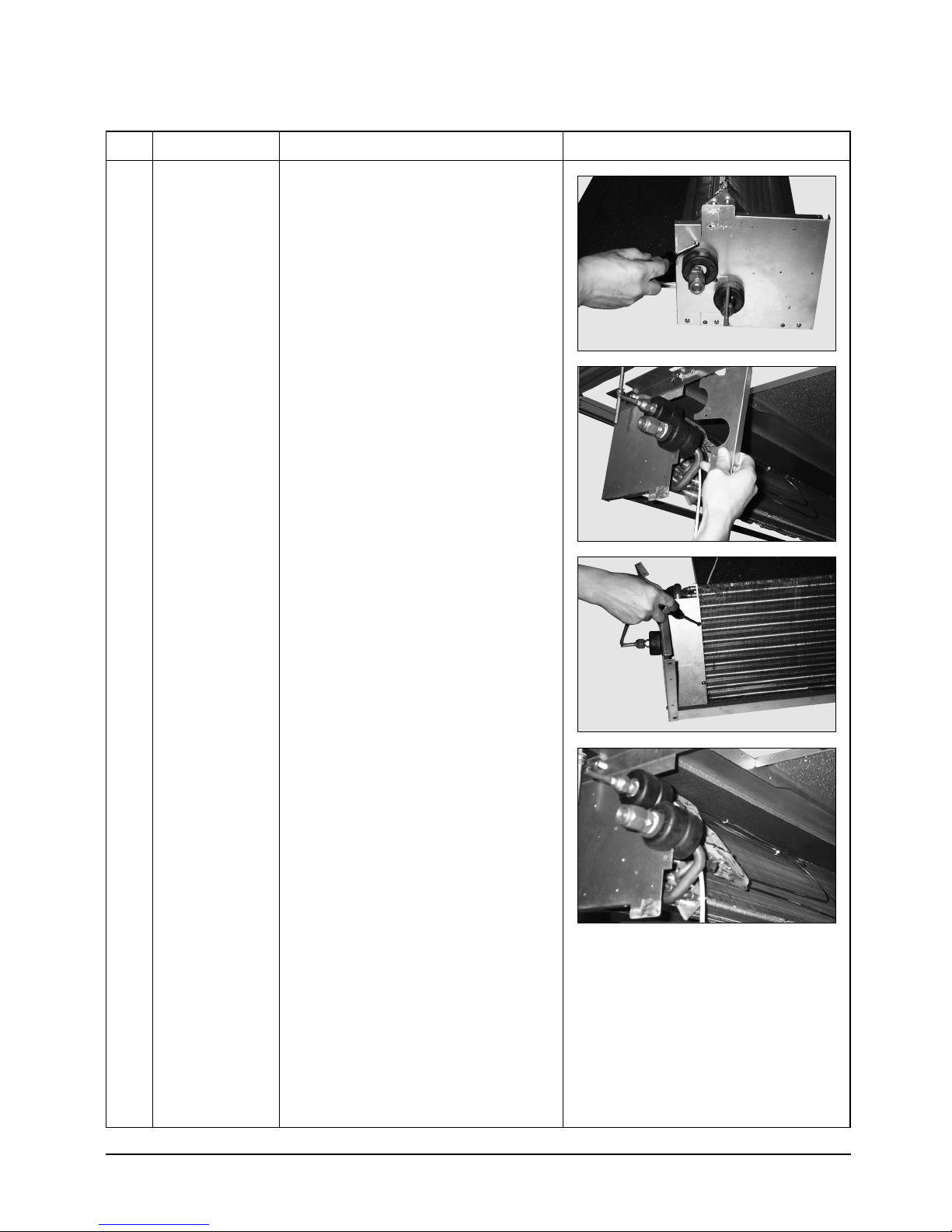
4
Drain Pan
1) Disassemble 4 indicating screws to
detach Ass'y Drain Pan.
(2 screws each at left and right side)
5
Evaporator
✳ Work is possible when disassembling the
Ass'y Drain Pan.
1) Disassemble 8 indicating screws.
(4 each at left and right side)
2) Disassemble 6 indicating screws.
3) Disassemble 5 indicating screws.
✳ It is possible at the status of No.3 Ass'y
Control In disassembly at the time.
9Samsung Electronics
Disassembly and Reassembly
No Parts Procedure Remark
4) After disassembling 4 indicating screws.
5) Pull the Cabinet-Side LF, RH by hand to
disassemble.
6) Separate 4 indicating screws.
(2 each at left and right side)
7) Detach it from the set if the Ass'y-Evap
pull up.
Samsung Electronics10

Disassembly and Reassembly
No Parts Procedure Remark
6
Holder Outlet
✳ When connecting canvas to the discharge
side.
1) Disassemble 4 indicating screws.
(2 each at left and right side)
2) Disassemble 12 indicating screws.
(6 each at upper and lower side)
✳ After connecting canvas to the
disassembled Ass'y Holder Outlet 2),
attach the Ass'y Holder Outlet to the
set in the reverse order.
11Samsung Electronics
2-2 Outdoor Unit
No Parts Procedure Remark
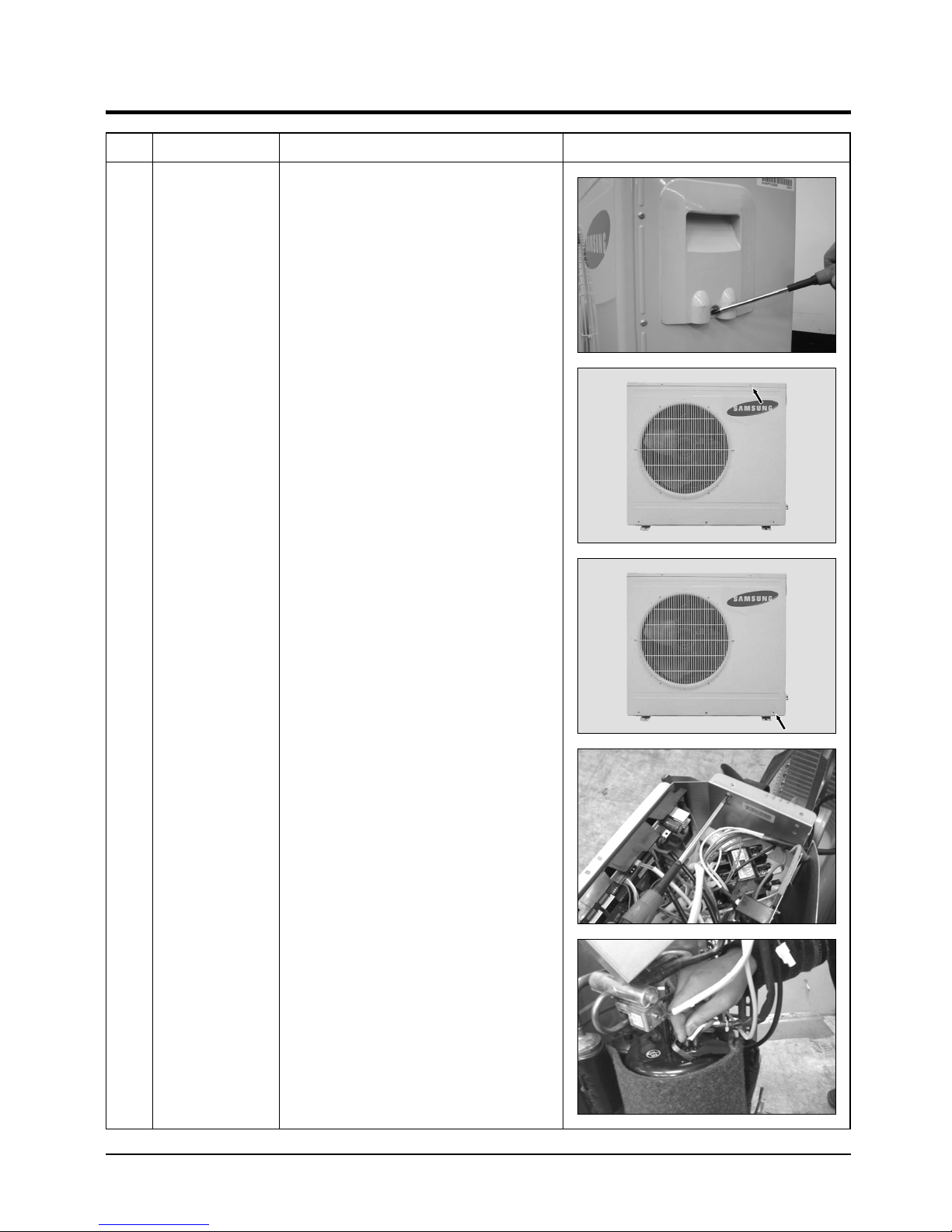
1 Common Work
1) Loosen the fixing screws and detach the
Cover Control.
2) Detach the connection wire from the
Terminal Block.
3) Loosen the fixing screws and detach the
Upper Cabinet.
4) Loosen the fixing screws and detach the
Front Cabinet.
5) Loosen 2 screws and pull up the
Control Box.
6) Detach the terminal cover and detach the
Comp lead wire.
Samsung Electronics12
 Loading...