

Samsung DH070EZM, UH070EZMC Service Manual
DUCT TYPE AIR CONDITIONER
INDOOR UNIT
DH070EZM
SERVICE
OUTDOOR UNIT
UH070EZMC
Manual
CONTENTSAIR CONDITIONER
1. Product Specifications
2. Installation
3. Disassembly and Reassembly
4. Refrigerating Cycle Diagram
5. T roubleshooting
6. Exploded Views and Parts List
7. PCB Diagram
8. Wiring Diagram
9. Schematic Diagram
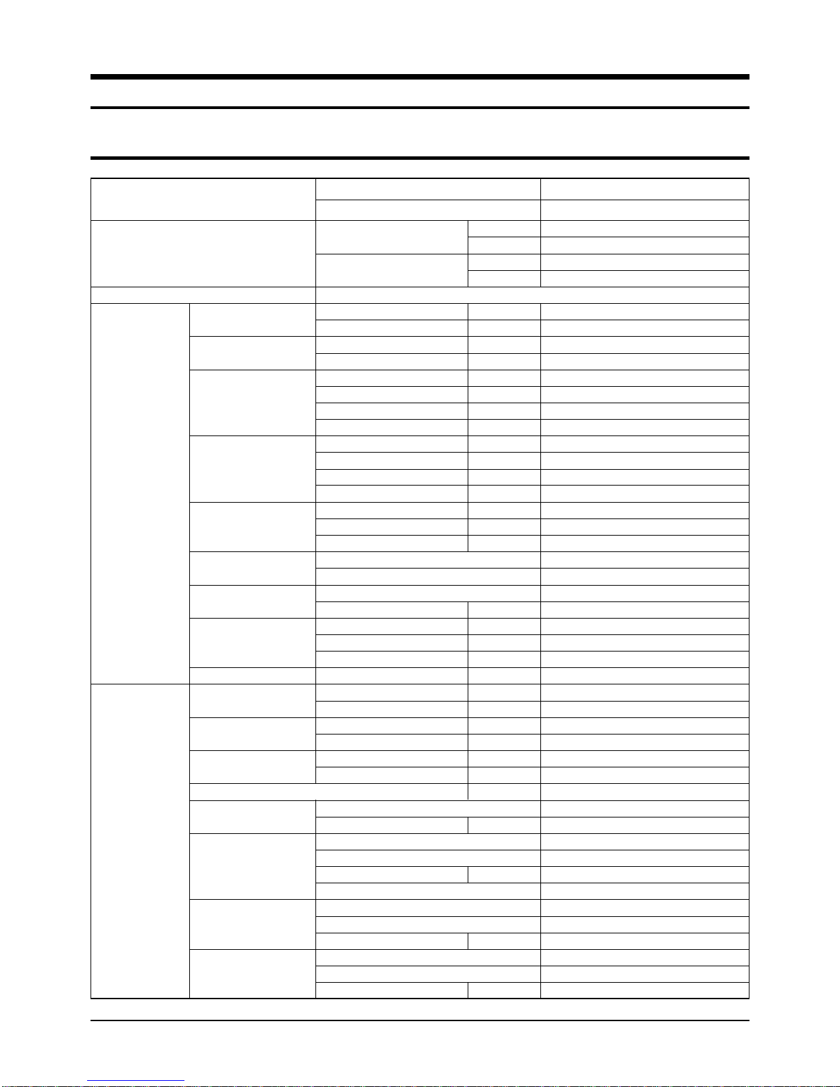
1. Product Specifications
1-1 Table
Indoor Unit
Outdoor Unit
MODEL
Capacity
Power Supply
Power Input
Running Current
Fan Speed
Air Circulation
Noise Level
(Sound Pressure)
Heat Exchanger
Fan
Dimension
Weight
Power Input
Running Current
Fan Speed
Sound Pressure Level
Fan
Compressor
Heat Exchanger
Refrigerant
INDOOR UNIT
OUTDOOR UNIT
Cooling
Heating
Cooling
Heating
Cooling
Heating
H.H
Hi
Mid
Low
U-High
High
Mid
Low
High
Mid
Low
Type
Row x Stages x Fin Pitch
Type
Motor Output
H
W
D
Net / Gross
Cooling
Heating
Cooling
Heating
High
Low
Type
Motor Output
Type
Model
Capacity
Protection
Type
Row x Stages x Fin Pitch
Face Area
Control
Type
Charge
Btu/hr
Watts
Btu/hr
Watts
1ø, 220-240V~, 50Hz
Watts
Watts
A
A
r.p.m
r.p.m
r.p.m
r.p.m
3
m
/min
3
m
/min
m3/min
3
/min
m
dB(A)
dB(A)
dB(A)
W
mm
mm
mm
kg
Watts
Watts
A
A
r.p.m
r.p.m
dB(A)
W
kW
2
m
kg
DH070EZM
UH070EZMC
23,900
7,000
26,300
7,700
200
200
1.0
1.0
1,050
950
900
850
19.5
17.5
16.5
15.5
46
45
44
D-fin coil
2 x 10 x 1.7(1,100mm)
Sirocco
97
260
1,340
600
41 / 47
2,250
2,250
11.2
11.2
820
400
57
Propeller Fan
60
Rotary
SHV33YC6-G
2.22
Internal
wave fin coil
2 x 24 x 1.5(900mm)
0.55
EEV
R-22
2.1
1Samsung Electronics

Table(cont.)
MODEL
Outdoor Unit
Condition
Piping
Notice : This model is tested under the external static pressure of 4mmAq.
Notice : Air Flow rate : Fan Step Control : Low → Mid → High → Ultra High
Dimension
Weight
Indoor Unit
Outdoor Unit
Pipe O.D. Size
Connection Method
Between
INDOOR UNIT
OUTDOOR UNIT
H
W
D
Net / Gross
Cool(DB/WB)
Heat(DB/WB)
Cool(DB/WB)
Heat(DB/WB)
Liquid
Gas
Height
Pipe Length
mm
mm
mm
kg
˚C
˚C
˚C
˚C
mm(inch)
mm(inch)
m
m
DH070EZM
UH070EZMC
638
880
310
67 / 72
27 / 19
20 / 15
35 / 24
7 / 6
9.52(3/8")
15.88(5/8")
Flare
Max. 15
Max. 30
Samsung Electronics2

1-2 Dimensions
1-2-1 Indoor Unit
(Unit : mm)
3Samsung Electronics

Product Specifications
1-2-2 Outdoor Unit
(Unit : mm)
310
(Front View) (Rear View)
638
660
880
Samsung Electronics4

2. Installation
2-1 Assigning Address to Indoor Unit
1. Before installing the indoor unit, assign an address to the indoor unit according to the air conditioning system plan.
2. The address of the indoor unit is assigned by adjusting MAIN(SW02) and RMC(SW01) rotary switches.
K1 K2 K3 K4
SW03
K5 K6 K7 K8
SW04
K9
K10
K11
K12
SW05
SW02 MAIN SW01 RMC
3. The MAIN address is for communication between the indoor unit and the outdoor unit.
Therefore, you must set it to operate the air conditioner properly.
4. It is required to set the RMC address if you install the wired remote controller and/or the centralized controller.
5. If you install optional accessories such as the wired remote controller, centralized controller, etc. see an appropriate
installation manual.
6. If an optional accessory is not installed, you do not have to set the RMC address. However, adjust K1 and K2 switches of
the SW03 DIP switch to "ON" position in this case.
7. Set the MAIN address by adjusting the rotary switch(SW02) from 0 to F. Each indoor unit connected to the same outdoor
unit must have different address.
7.
i. e. If an indoor unit does not have an optional accessory and its
MAIN address is "4".
K1 K2 K3 K4
K5 K6 K7 K8
K9
K10
K11
K12
SW03
SW04
SW05
SW02 MAIN
SW01 RMC
5Samsung Electronics

2-2 Additional Functions
K5 K6 K7 K8
K5 K6 K7 K8
K5 K6 K7 K8
■ Compensation for lost temperature in heating operation
■
• Reduces the difference between an actual room temperature and a sensed
■
• temperature by the air conditioner when heating.
Switch No. Switch ON Switch OFF
K5 2°C compensation 5°C compensation
■ Adjusting filter cleaning cycle
■
• You can adjust the cycle for filter sign indicator.
Switch No. Switch ON Switch OFF
K6 1000 hours 2000 hours
■ Hot water heater
■
• You must adjust the K7 when you install the hot water heater.
SW04
SW04
Switch No. Switch ON Switch OFF
K7 No use of hot water heater Use of hot water heater
SW04
Samsung Electronics6
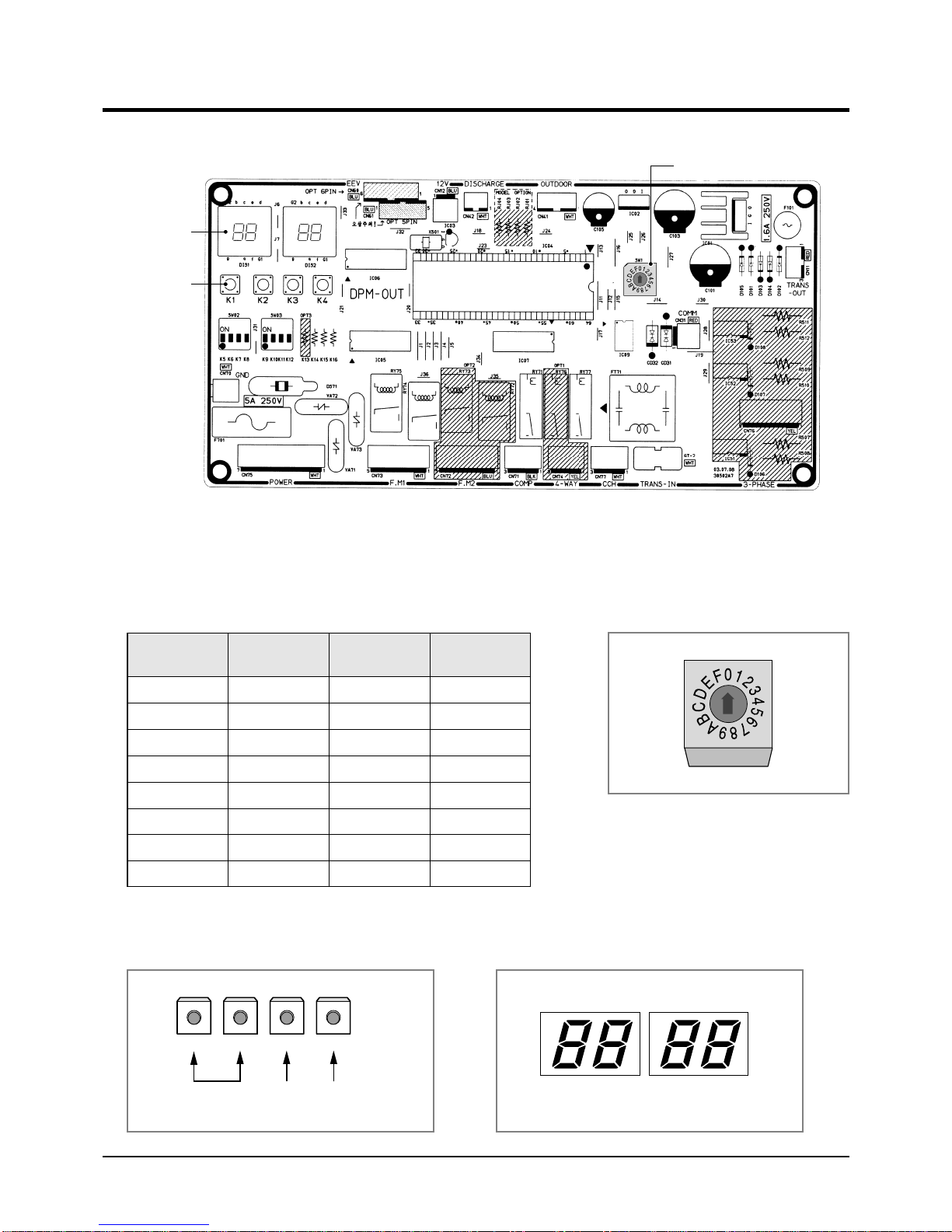
2-3 Setting Up Option Switches
■ Option Switch
Display
Key
■ Rotary Switch
■
You should display that how many indoor units are connected to the
outdoor unit. Refer to the table below, then turn the arrow to appropriate
position.
Rotary Switch
Switch No.
0 or 1
2
3
4
5
6
7
8
Number of
indoor unit(s)
One
Two
Three
Four
Five
Six
Seven
Eight
Switch No.
9
A
B
C
D
E
F
-
Number of
indoor unit(s)
Nine
Ten
Eleven
Twelve
Thirteen
Fourteen
Fifteen
-
■ KEY ■ Display
K1 K2 K3 K4
RESETCHECK MODE DISPLAY
MODE
DIS 1
SEG 1 SEG 2 SEG 3 SEG 4
DIS 2
7Samsung Electronics
Installation
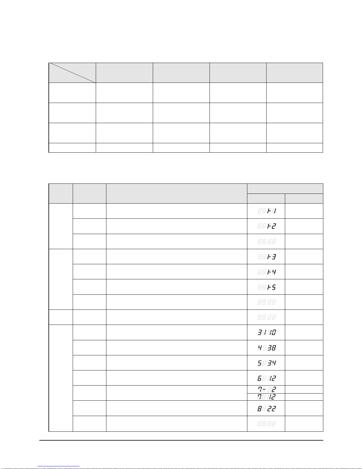
■ Summary of KEY functions
Number
of press times
✳ Use the K1 only for heat pump models.
Function
(Displayed on SEG 3, 4)
1
2
3
4
K1
Adding refrigerant at
heating mode
Test operation at
heating mode
End
-
■ Reading data indicated on the display
KEY
K1
Number of
press
1
2
Adding refrigerant for heat pump models
Test operation for heat pump models
(Displayed on SEG 3, 4)
K2
Adding refrigerant at
cooling mode
Test operation at
cooling mode
Pump Down for recovery
of refrigerant
End
Item
(Displayed on SEG 3, 4)
K3
Reset
-
-
-
Display Meaning
(Displayed on SEG 3, 4)
K4
Displays data
-
-
-
Example
K2
K3
K4
3
1
2
3
4
1
2
3
4
5
6
End
Adding refrigerant for cooling only models
Test operation for cooling only models
Pump Down for recovery of refrigerant
End
Reset
Discharge temperature of compressor
Temperature of outdoor heat exchanger
Outdoor temperature
Step of electronic expansion valve
(0 step : all closed, 480 step : all open)
Temperature of evaporator
Indoor temperature
110 °C
38 °C
34 °C
120STEP
(12 x 10)
-2 °C
12 °C
22 °C
7
Stopping view mode & display communication data
Samsung Electronics8
3. Disassembly and Reassembly
Stop operation of the air conditioner and remove the power cord before repairing the unit.
3-1 Indoor Unit
No Parts Procedure Remark
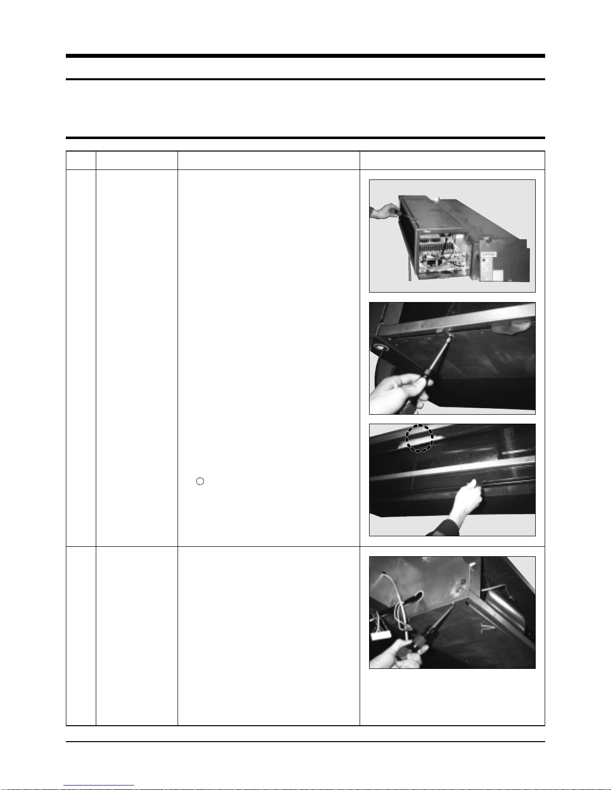
1
Filter-pre
1) Disassemble 2 screws of indication part
and then assemble the direction of
2 plate-handle places by use of screw
as shown in 2).
2) Turn the plate handle by hand when
removing the Filter-pre.
3) When pulling the Filter-pre handle,
the Filter-pre can be assembled.
✳ Be sure to remove the cushion on the
marked part after initial installation.
(It cause the damage of noise).
2
Blower & DUCT
1) After disassembling 9 places indicating
screws, separate Ass'y cover bottom.
9Samsung Electronics

Disassembly and Reassembly
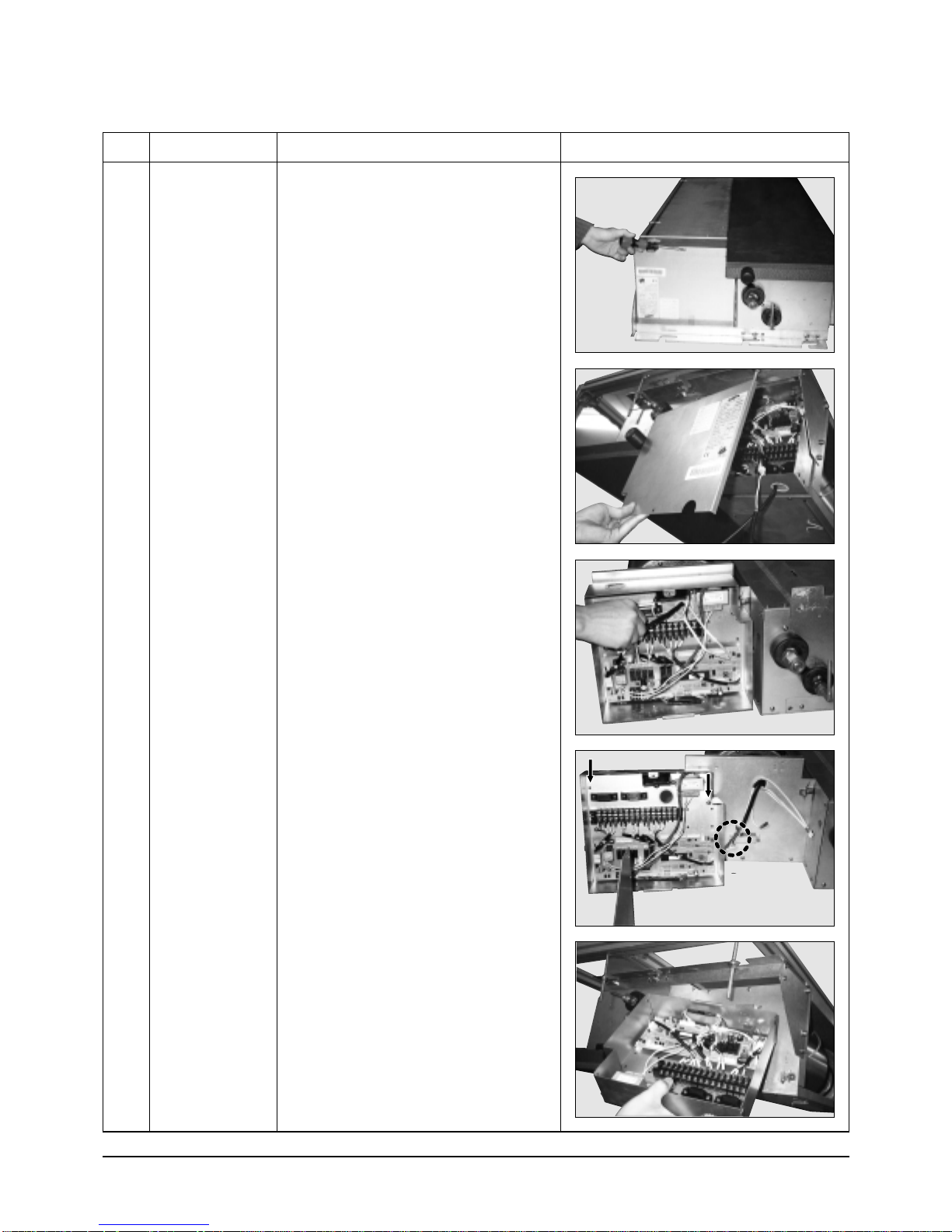
No Parts Procedure Remark
2) Disassemble 6 indicating screws.
3) Separate the sensor holder from the
Ass'y fan case.
4) Separate from Ass'y control in the
capacitor connection wire between the
motor-fan in and housing connector.
5) Separate the Ass'y blower and duct from
the set.
Samsung Electronics10
Disassembly and Reassembly
No Parts Procedure Remark
3 Control In
1) After disassembling 1 indicating screw,
separate the cover-control.
2) Separate the motor-fan in and sensor
connector connected to PCB.
3) Disassemble 2 indicating screws.
(arrow mark)
4) Hold the Ass'y control In by hand to lift up
a little and then release the status of
hanging on the hanging slot.
11Samsung Electronics

Disassembly and Reassembly
No Parts Procedure Remark
4
Drain pan
1) Disassemble 4 indicating screws to
separate Ass'y drain pan. (2 screws
each at left and right side)
5
EVAP
✳ Work is possible when disassembling the
ass'y drain pan.
1) Disassemble 8 indicating screws. (4 each
at left and right side)
2) Disassemble 6 indicating screws.
3) Disassemble 5 indicating screws.
✳ It is possible at the status of No.3 Ass'y
control In disassembly at the time.
Samsung Electronics12
 Loading...