

Refer to the service manual in the GSPN(see the rear cover) for the more information.
AIR CONDITIONER THE FEATURE OF PRODUCT
SYSTEM AIR CONDITIONER
INDOOR UNIT OUTDOOR UNIT
Basic : TH026EAV UH026EAV
TH035EAV UH035EAV
TH052EAV UH052EAV
TH060EAV UH060EAV
Model
: TH026EAV1 UH026EAV1
TH035EAV1 UH035EAV1
TH052EAV1 UH052EAV1
TH060EAV1 UH060EAV1
Model Code : TH026EAV1 UH026EAV1
Model Code : TH035EAV1 UH035EAV1
Model Code : TH052EAV1 UH052EAV1
Model Code : TH060EAV1 UH060EAV1
■ Energy Saving Function
■ Long Lasting Outdoor Unit
■ High Ceiling Operation
■ : Up to 3.6m height
■ Built-in Drain Pump
■ : Max. 750mm
■ Long Piping
■ : Max. 50m long & 30m height
TH026EAV1/TH035EAV1
TH052EAV1/TH060EAV1
UH026EAV1/UH035EAV1
UH052EAV1
UH060EAV1
29347A(1)_co.indd 1 2008-01-23 ソタネト 2:00:14

Operating Instructions and Installation
Samsung Electronics 1
Contents
11. Precautions
. ...... .... ... .... ...... ...... ...... .... ...... ...... .... ... .... ... .... ...... ...... .... ... .... ... .... ...... ...... .... ... .... ... .... ......
1-1
1-1 Installing the air conditioner
...... .... ... .... ...... ...... .... ... .... ... .... ...... ...... .... ... .... ... .... ...... ...... .... ... .... ... ...
1-1
1-2 Power supply and circuit breaker
.... ...... .... ... .... ...... ...... ...... .... ...... ...... .... ... .... ... .... ...... ...... .... ... .... .
1-1
1-3 During operation
. ...... ...... .... ... .... ... .... ...... ...... .... ... .... ... .... ...... ...... .... ... .... ... .... ...... ...... .... ... .... ... .... .....
1-1
1-4 Disposing of the unit
..... .... ... .... ...... ...... .... ... .... ... .... ...... ...... .... ... .... ... .... ...... ...... .... ... .... ... .... ...... ......
1-2
1-5 Others
..... .... ... .... ... .... ...... ...... .... ... .... ... .... ...... ...... .... ... .... ... .... ...... ...... .... ... .... ... .... ...... ...... .... ... .... ... .... .
1-2
12. Product Specifications
.... ...... .... ... .... ... .... ...... ...... .... ... .... ... .... ...... ...... .... ... .... ... .... ...... ...... .... ... ...
2-1
2-1 The Feature of Product
... .... ... .... ...... ...... .... ... .... ... .... ...... ...... .... ... .... ... .... ...... ...... .... ... .... ... .... ...... ......
2-1
2-2 Product Specifications
.. .... ...... ...... .... ... .... ... .... ...... ...... .... ... .... ... .... ...... ...... .... ... .... ... .... ...... ...... .... ... ..
2-2
2-3 The Comparative Specifications of Product
... ... .... ... .... ...... ...... .... ... .... ... .... ...... ...... .... ... .... ... .... ...
2-3
2-4 Accessory and Option Specifications
..... ...... .... ... .... ... .... ...... ...... .... ... .... ... .... ...... ...... .... ... .... ... .... ..
2-4
13. Alignment and Adjustments
.... ...... .... ...... ...... .... ... .... ... .... ...... ...... .... ... .... ... .... ...... ...... .... ... ...
3-1
3-1 Indoor Display Error and Check Method
.. ...... .... ...... ...... .... ... .... ... .... ...... ...... .... ... .... ... .... ...... ...... .
3-1
3-2 Setting Option Setup Method
... ... .... ...... ...... .... ... .... ... .... ...... ...... .... ... .... ... .... ...... ...... .... ... .... ... .... ...
3-6
14. Disassembly and Reassembly
..... .... ... .... ...... ...... .... ... .... ... .... ...... ...... .... ... .... ... .... ...... ...... .... .
4-1
4-1 Indoor Unit
.. .... ... .... ... .... ...... ...... .... ... .... ... .... ...... ...... .... ... .... ... .... ...... ...... .... ... .... ... .... ...... ...... .... ... .... ...
4-1
4-2 Outdoor Unit
... ...... .... ... .... ... .... ...... ...... .... ... .... ... .... ...... ...... .... ... .... ... .... ...... ...... .... ... .... ... .... ...... ...... ....
4-10
15. Exploded Views and Parts List
. ...... .... ...... ...... .... ... .... ... .... ...... ...... .... ... .... ... .... ...... ...... .... ... ...
5-1
5-1 Indoor Unit
. ... .... ...... ...... .... ... .... ... .... ...... ...... .... ... .... ... .... ...... ...... .... ... .... ... .... ...... ...... .... ... .... ... .... ...... ...
5-1
5-2 Panel
. ...... ...... .... ... .... ... .... ...... ...... .... ... .... ... .... ...... ...... .... ... .... ... .... ...... ...... .... ... .... ... .... ...... ...... .... ... .... ... .
5-3
5-3 Outdoor Unit
... ...... ...... .... ... .... ...... ...... .... ... .... ... .... ...... ...... .... ... .... ... .... ...... ...... .... ... .... ... .... ...... ...... .... .
5-5
5-4 ASS'Y Control Out
. .... ... .... ... .... ...... ...... .... ... .... ... .... ...... ...... .... ... .... ... .... ...... ...... .... ... .... ... .... ...... ...... ....
5-11
16. Electrical Parts List
.... .... ...... ...... .... ... .... ... .... ...... ...... .... ... .... ... .... ...... ...... .... ... .... ... .... ...... ...... .... ... ..
6-1
17. Wiring Diagram
.... .... ... .... ... .... ...... ...... .... ... .... ... .... ...... ...... .... ... .... ... .... ...... ...... .... ... .... ... .... ...... ...... ..
7-1
18. Schematic Diagram
. ...... ...... .... ... .... ... .... ...... ...... .... ... .... ... .... ...... ...... .... ... .... ... .... ...... ...... .... ... .... ... .
8-1
8-1 Indoor Unit
.. .... ... .... ... .... ...... ...... .... ... .... ... .... ...... ...... .... ... .... ... .... ...... ...... .... ... .... ... .... ...... ...... .... ... .... ... .
8-1
8-2 Outdoor Unit
... ...... .... ... .... ... .... ...... ...... .... ... .... ... .... ...... ...... .... ... .... ... .... ...... ...... .... ... .... ... .... ...... ...... ....
8-2
29347A(1)_1.indd 1 2008-01-23 ソタネト 1:40:06

Operating Instructions and Installation
2 Samsung Electronics
Contents
19. Circuit Descriptions
.. .... ... .... ...... ...... ...... .... ...... ...... .... ... .... ... .... ...... ...... .... ... .... ... .... ...... ...... .... ... ....
9-1
9-1 PCB Circuit Descriptions
.. ...... ...... ...... .... ...... ...... .... ... .... ... .... ...... ...... .... ... .... ... .... ...... ...... .... ... .... ... ...
9-1
9-2 Refrigerating Cycle Diagram
... ... .... ... .... ...... ...... .... ... .... ... .... ...... ...... .... ... .... ... .... ...... ...... .... ... .... ... ...
9-6
10. PCB Diagram
. ... .... ... .... ...... ...... .... ... .... ... .... ...... ...... .... ... .... ... .... ...... ...... .... ... .... ... .... ...... ...... .... ... .... ... ..
10-1
10-1 Indoor PCB
. .... ... .... ...... ...... .... ... .... ... .... ...... ...... .... ... .... ... .... ...... ...... .... ... .... ... .... ...... ...... .... ... .... ... .... ...
10-1
10-2 Outdoor PCB
.. ...... .... ... .... ...... ...... .... ... .... ... .... ...... ...... .... ... .... ... .... ...... ...... .... ... .... ... .... ...... ...... .... ... ...
10-2
11. Troubleshooting
.... .... ... .... ...... ...... .... ... .... ... .... ...... ...... .... ... .... ... .... ...... ...... .... ... .... ... .... ...... ...... .... ... ..
11-1
11-1 Items to be checked first
.... .... ... .... ...... ...... .... ... .... ... .... ...... ...... .... ... .... ... .... ...... ...... .... ... .... ... .... .....
11-1
11-2 Fault Diagnosis by Symptom
... .... ... .... ... .... ...... ...... .... ... .... ... .... ...... ...... .... ... .... ... .... ...... ...... .... ... ...
11-2
11-3 PCB Inspection Method
... ...... ...... .... ... .... ... .... ...... ...... .... ... .... ... .... ...... ...... .... ... .... ... .... ...... ...... .... ...
11-22
11-4 Main Part Inspection Method
...... .... ... .... ...... ...... .... ... .... ... .... ...... ...... .... ... .... ... .... ...... ...... .... ... .... ..
11-24
12. Reference Sheet
.. ... .... ...... ...... .... ... .... ... .... ...... ...... .... ... .... ... .... ...... ...... .... ... .... ... .... ...... ...... .... ... .... ... ..
12-1
12-1 Index for Model Name
.. ... .... ...... ...... .... ... .... ... .... ...... ...... .... ... .... ... .... ...... ...... .... ... .... ... .... ...... ...... ...
12-1
12-2 Pressure Graph
.. ...... ...... ...... .... ...... ...... .... ... .... ... .... ...... ...... .... ... .... ... .... ...... ...... .... ... .... ... .... ...... ...... ..
12-2
12-3 Pressure & Capacity mark
..... .... ... .... ... .... ...... ...... .... ... .... ... .... ...... ...... .... ... .... ... .... ...... ...... .... ... .... ...
12-4
12-4 Q & A for Non-trouble
.. ...... .... ... .... ... .... ...... ...... .... ... .... ... .... ...... ...... .... ... .... ... .... ...... ...... .... ... .... ... ...
12-5
12-5 Cleaning/Filter Change
..... ...... .... ... .... ...... ...... ...... .... ...... ...... .... ... .... ... .... ...... ...... .... ... .... ... .... ...... ...
12-8
12-6 Installation
...... ...... .... ... .... ...... ...... ...... .... ...... ...... .... ... .... ... .... ...... ...... .... ... .... ... .... ...... ...... .... ... .... ... ....
12-9
12-7 Installation Diagram of Indoor Unit and Outdoor Unit
.. .... ... .... ... .... ...... ...... .... ... .... ... .... ...... ..
12-10
29347A(1)_1.indd 2 2008-01-23 ソタネト 1:40:06
Samsung Electronics 1-1
1. Precautions
1-1 Installing the air conditioner
● Users should not install the air conditioner by themselves.
Ask the dealer or authorized company to install the air conditioner except the window-type air conditioner in U.S.A and Canada.
● If you don’t install the air conditioner properly, it may cause a fire, a water leakage or an electric shock.
● You must install the air conditioner according to the national wiring regulations and safety regulations.
● Install the indoor unit higher than 2.5m from the floor to avoid the injury caused by the operation of the fan.
(except the window-type air conditioner)
● The manufacturer is not responsible for any accidents or injury caused by an incorrect installation.
● When installing the built-in type air conditioner, keep all electric cables such as the power cable and the connection cord in pipes,
ducts, or cable channels to protect them from the danger of impact or any other incidents.
1-2 Power supply and circuit breaker
● If the power cord of the air conditioner is damaged, it must be replaced by the manufacturer or a qualified person in order to avoid
a hazard.
● The air conditioner must be plugged into an independent circuit if applicable or connect the power cable to the auxiliary circuit
breaker.
An all pole disconnection from the power supply must be incorporated in the fixed wiring with a contact opening of >3mm.
● Do not extend an electric cord to the air conditioner.
● The air conditioner must be plugged in after you complete the installation.
1-3 During operation
● Do not repair the air conditioner at your discretion.
It is recommended to contact a service center directly.
● Never spill any kind of liquid on the air conditioner.
If this happens, turn off the air conditioner and contact an authorized service center.
● Do not insert anything between the airflow blades to prevent damage of the inner fan and consequent injury.
Keep children away from the air conditioner.
● Do not place any obstacles in front of the air conditioner.
● Do not spray any kind of liquid into the indoor unit. If this happens, turn off the air conditioner and contact a service center.
● Make sure that the air conditioner is well ventilated at all times:
Do not place a cloth or other materials over it.
● Remove the batteries if you don’t use the remote control for a long time. (If applicable)
● Use the remote control within 7 meters from the indoor unit. (If applicable)
29347A(1)_1.indd 1 2008-01-23 ソタネト 1:40:06
1-2 Samsung Electronics
1-4 Disposing of the unit
● Before throwing out the air conditioner, remove the batteries from the remote control.
● When you dispose of the air conditioner, consult your dealer. If pipes are removed incorrectly, refrigerant may blow out and cause
air pollution. When it contacts with your skin, it can cause skin injury.
● The package of the air conditioner should be recycled or disposed of properly for environmental reasons.
1-5 Others
● Never store or load the air conditioner upside down or sideways to prevent the damage to the compressor.
● Young children or infirm persons should be always supervised when they use the air conditioner.
● Max current is measured according to IEC standard for safety.
● Current is measured according to ISO standard for energy efficiency.
29347A(1)_1.indd 2 2008-01-23 ソタネト 1:40:07
Samsung Electronics 2-1
2. Product Specifications
2-1 The Feature of Product
■ Energy saving function
Makes a room cool with and energy saving and arises the efficiency of air conditioner.
■ Long Lasting Outdoor Unit
Anti-Corrosion Cabinet & Cluster Gold Heat Exchanger(Cooling only).
■ High Ceiling Operation
Broader and wider blow supports up to 3.6 meters high.
■ Built-in Drain Pump
Drain Pump for 750mm height difference.
■ Auto Changeover
Cooling or Heating automatic operation due to room temperature.
■ Long Piping
Max. 50m long & 30m height.
29347A(1)_1.indd 1 2008-01-23 ソタネト 1:40:07

2-2 Samsung Electronics
2-2 Product Specifications
MODEL
INDOOR UNIT TH026EAV1 TH035EAV1 TH052EAV1 TH060EAV1
OUTDOOR UNIT UH026EAV1 UH035EAV1 UH052EAV1 UH060EAV1
Capacity
Cooling
BTU/h 9,000 12,000 18,000 21,000
W 2,600 3,500 4,700 5,800
Heating
BTU/h 11,000 14,000 21,000 25,000
W 3,300 4,000 5,500 7,000
Power Supply ø/V/Hz 1/220~240/50
Power
Input
Cooling
W 730 1,090 1,460 1,930
Heating
W 900 1,100 1,590 2,180
Running
Current
Cooling
A 3.4 5.0 6.7 8.8
Heating
A 4.3 5.1 7.4 10.0
Indoor Unit
Fan Speed
Hi r.p.m 580 650 770 820
Mid r.p.m 540 570 710 780
Low r.p.m 500 500 630 730
Air Flow
Hi
m3/min 11 11 13 15
Mid
m3/min - - - -
Low
m3/min - - - -
Noise Level(Sound Pressure) dB(A)
46
↓ 46↓ 47↓ 49↓
Heat Exchanger
Type Slit
Row×Stages×Fin pitch 2×10×1.4mm
Fan Type Turbo
Demension
W mm 575
H mm 260
D mm 575
Weight Net/Gross kg 15.7/19.2
Outdoor Unit
Fan Speed
Hi r.p.m 900 900 900 780
Low r.p.m 500 500 680 520
Noise Level(Sound Pressure) dB(A)
51
↓ 53↓ 58↓ 60↓
Fan Type Propeller
Compressor
Type Inverter
Model G4C090LUDER G4C090LUDER G8T200FUAEW G8T260FUAEW
Motor Output kW 0.853 0.853 2.0 2.4
Protection External
Refrigerant
Type R410A
Charge
g 950 950 1,450 1,500
Adding Charge g/m chargeless chargeless 30 30
Control Expansion Valve
Heat Exchanger
Type G-fin
Row×Stages×Fin pitch 1×24×1.3mm 1×24×1.3mm 2×28×1.3mm 2×36×1.3mm
Demension
W mm 790 790 880 880
H mm 548 548 638 798
D mm 285 285 310 310
Weight Net/Gross kg 32.6/35.4 32.6/35.4 50/53 57/61
Piping
Pipe O.D Size
Liquid mm(inch) 6.35(1/4") 6.35(1/4") 6.35(1/4") 6.35(1/4")
Gas mm(inch) 9.52(3/8") 9.52(3/8") 12.7(1/2") 15.88(5/8")
Connection Method Flare
Between
Height
m Max.15 Max.15 Max.30 Max.30
Pipe Lenth
m Max.20 Max.20 Max.50 Max.50
29347A(1)_1.indd 2 2008-01-23 ソタネト 1:40:07
Samsung Electronics 2-3
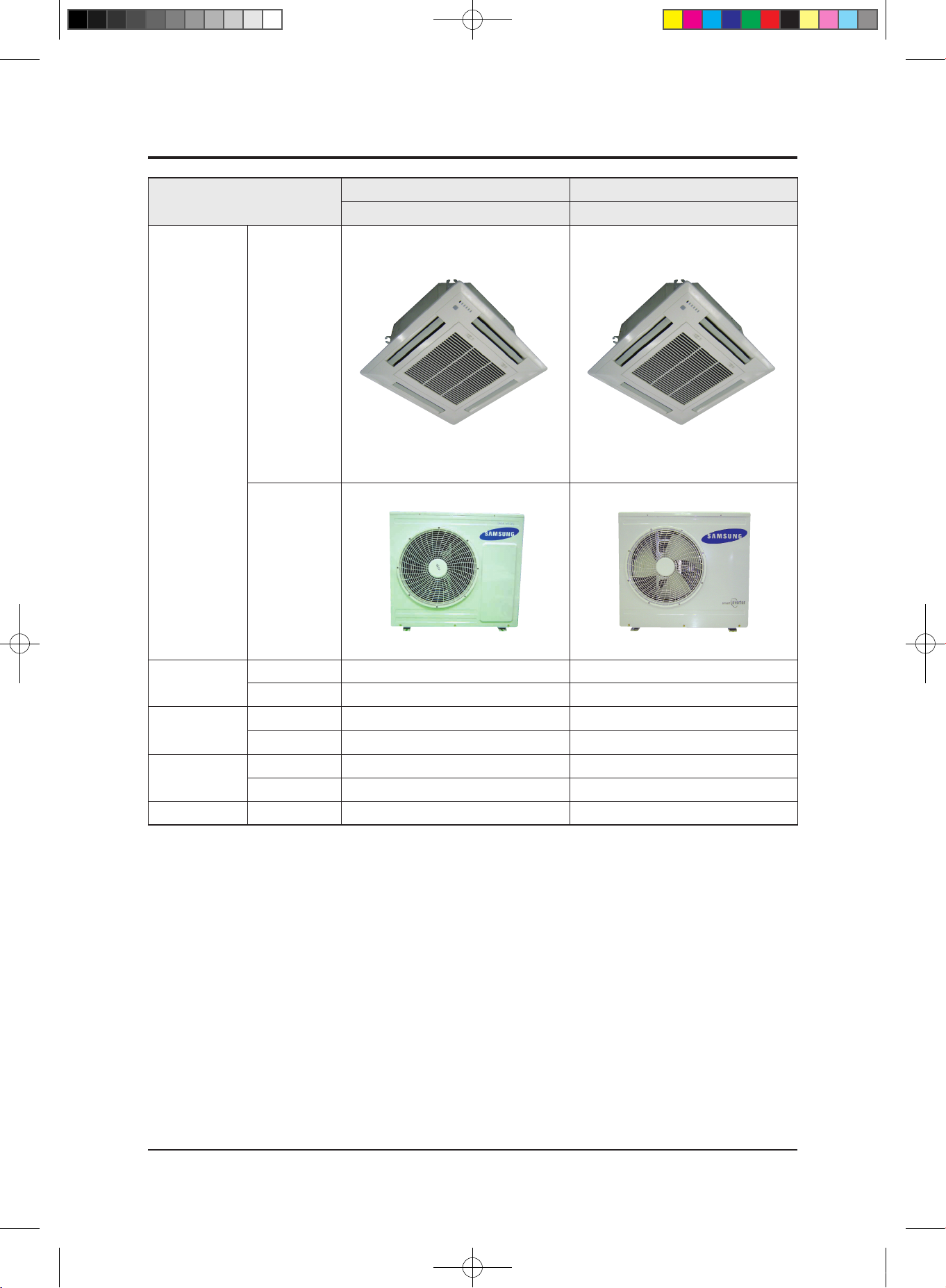
2-3 The Comparative Specifications of Product
Item
Development Model Comparative Model
TH060EAV1 TH060EAV
Design
Indoor Unit
Outdoor Unit
Net Weight
Indoor Unit 15.7kg 17.0kg
Outdoor Unit 61.0kg 61.0kg
Outer Dimension
(WidthxHeightxDepth)
Indoor Unit 575×260×575mm 575×260×575mm
Outdoor Unit 880×798×310mm 880×798×310mm
Noise
Indoor Unit
49dB↓ 49dB↓
Outdoor Unit
60dB
↓ 60dB↓
Air Purifying System Filter Anti-bacterial Filter Anti-bacterial Filter
29347A(1)_1.indd 3 2008-01-23 ソタネト 1:40:07
2-4 Samsung Electronics
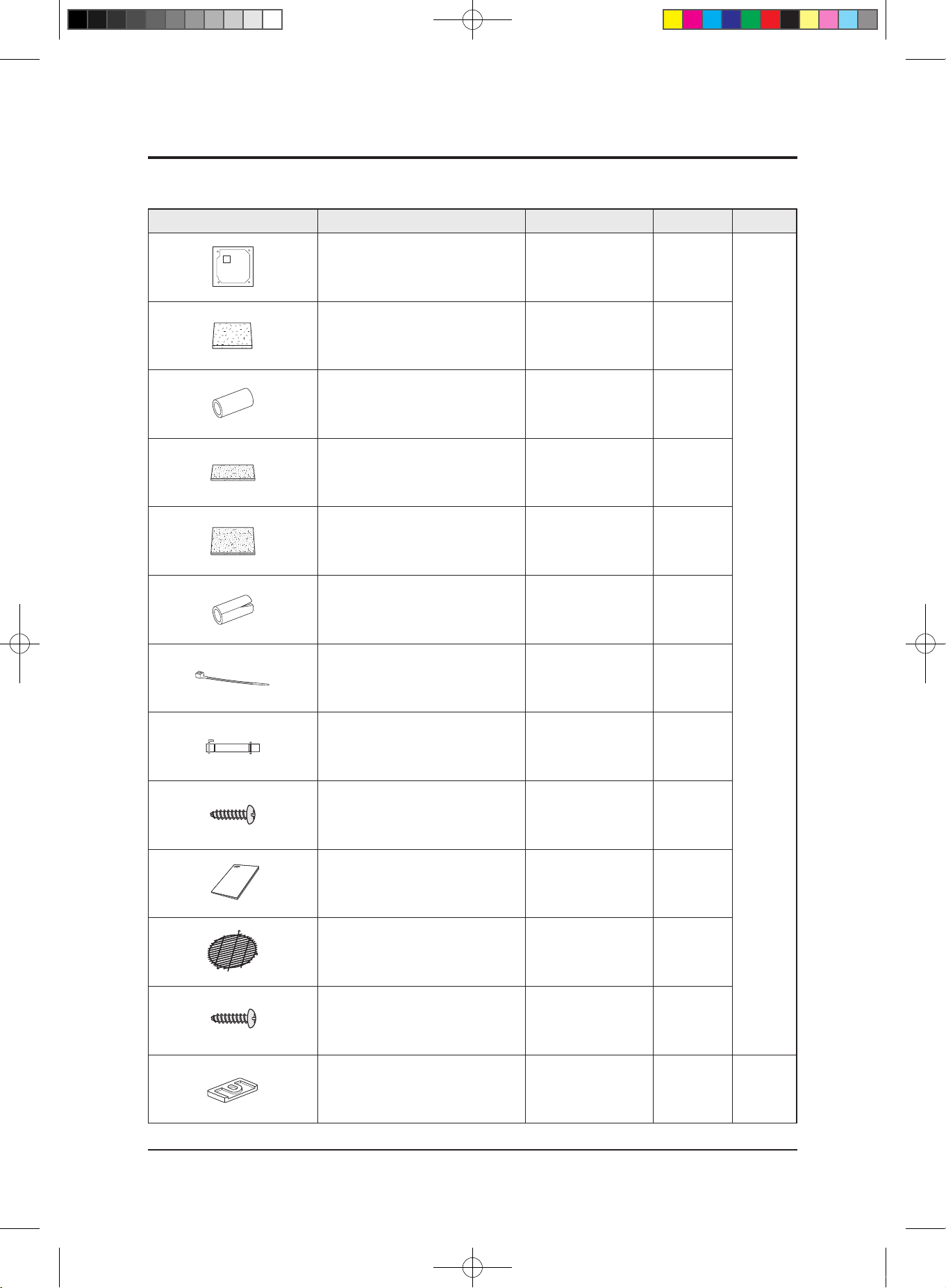
2-4 Accessory and Option Specifications
2-4-1 Accessories
Item Descriptions Code-No. Q'TY Remark
Pattern sheet
DB69-01369A 1
Indoor
Unit
Insulation cover drain DB62-01959A
1
Insulation drain DB62-01960B
1
Insulation cover band DB72-00109J
1
Insulation drain A DB72-00190G
2
Insulation install inlet DB72-00143E
2
Cable-tie DB65-00191A
5
Flexible hose DB94-01258C
1
M4x12 tapped Screw 6002-000213
4
Installation manual DB98-24340A
1
Safety net
DB63-01372A 1
M4x12 tapped Screw
6002-000213 3
Rubber leg
DB73-20134A 4
Outdoor
Unit
29347A(1)_1.indd 4 2008-01-23 ソタネト 1:40:08
Samsung Electronics 2-5
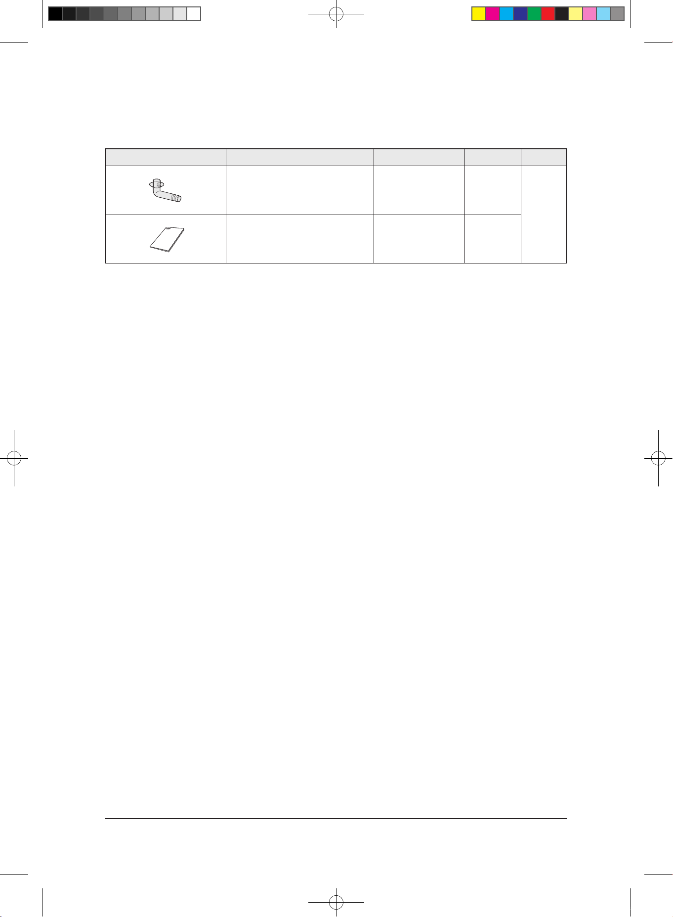
Item Descriptions Code-No. Q'TY Remark
Drain Plug DB67-20011A
1
Outdoor
Unit
Installation manual DB98-28806A
1
Accessories(cont.)
Product Specifications
29347A(1)_1.indd 5 2008-01-23 ソタネト 1:40:08

2-6 Samsung Electronics
Item Descriptions Code-No. Q'TY Remark
Wireless remote controller DB93-04858C
1
Battery DB47-90024A
2
Remote control holder DB61-03147A
1
STS 2S-2x10 tapped screw 6002-000581
2
User manual DB98-27997A
1
Installation manual DB98-27999A
1
■
Wireless Remote Controller
Product Specifications
29347A(1)_1.indd 6 2008-01-23 ソタネト 1:40:08
Operating Instructions and Installation
Samsung Electronics 2-7
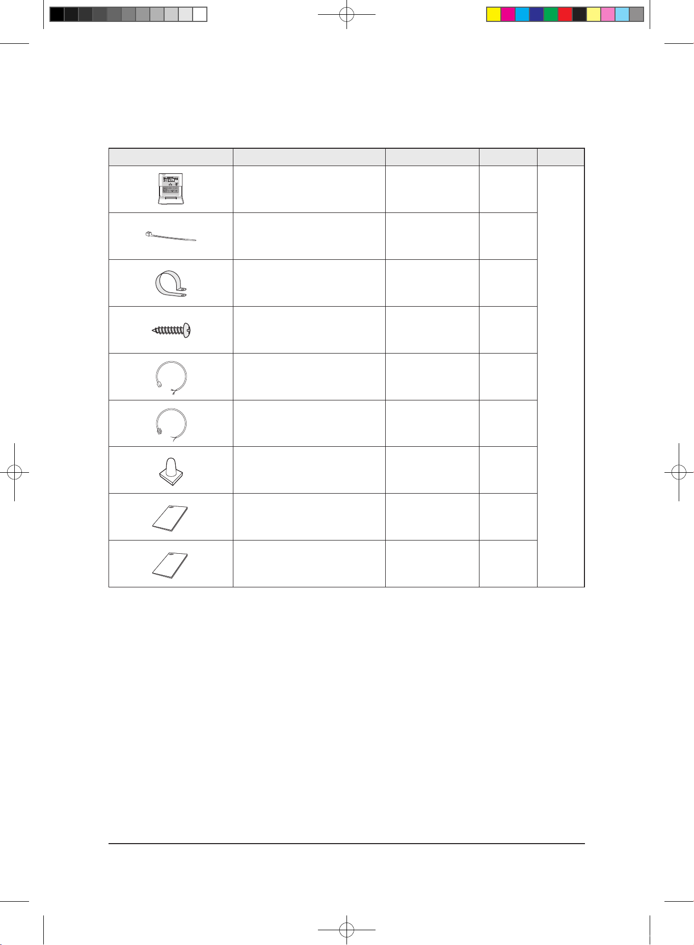
Item Descriptions Code-No. Q'TY Remark
Wired remote controller DB93-01766H
1
Cable-tie DB65-10088B
2
Cable clamp DB65-10074E
5
M4x16 tapped screw 6002-000474
7
Indoor unit power drawing cable DB39-00221A
1
Communication cable of the
wired remote controller
DB39-00933A
1
Wire joint DB39-90020A
1
User manual DB98-15731A
1
Installation manual DB98-15770A
1
■ Wired Remote Controller
Product Specifications
29347A(1)_1.indd 7 2008-01-23 ソタネト 1:40:09
2-8 Samsung Electronics
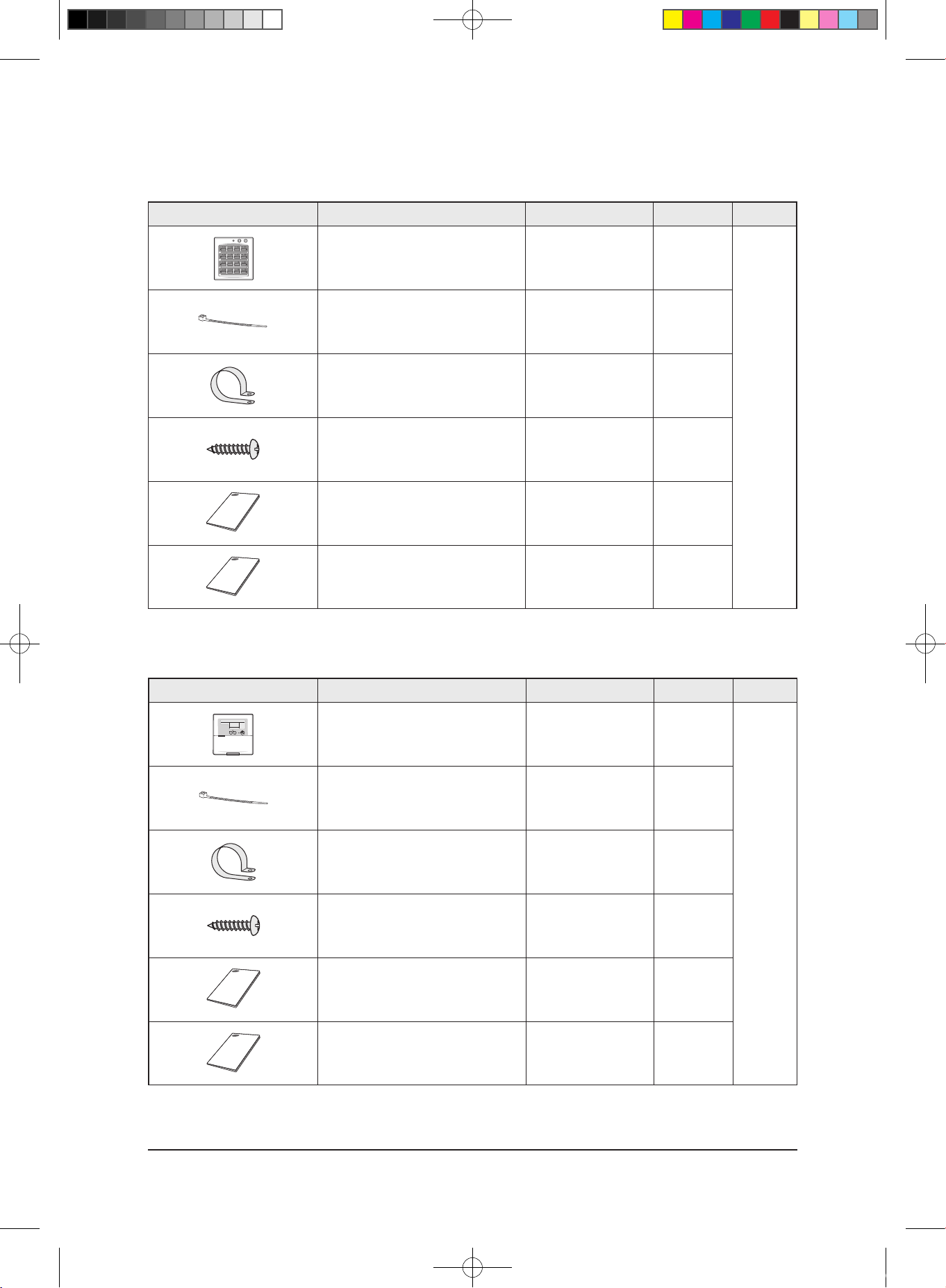
■ Centralized Controller
Item Descriptions Code-No. Q'TY Remark
Centralized controller DB93-03425C
1
Cable-tie DB65-10088B
2
Cable clamp DB65-10074E
5
M4x16 tapped screw 6002-000474
7
User manual
DB98-12721A
1
Installation manual
DB98-25773A
1
■ Function Controller
Item Descriptions Code-No. Q'TY Remark
Function controller DB93-00757G
1
Cable-tie DB65-10088B
2
Cable clamp DB65-10074E
6
M4x16 tapped screw 6002-000474
7
User manual
DB98-27317A
1
Installation manual
DB98-27315A
1
Product Specifications
29347A(1)_1.indd 8 2008-01-23 ソタネト 1:40:10
Samsung Electronics 2-9
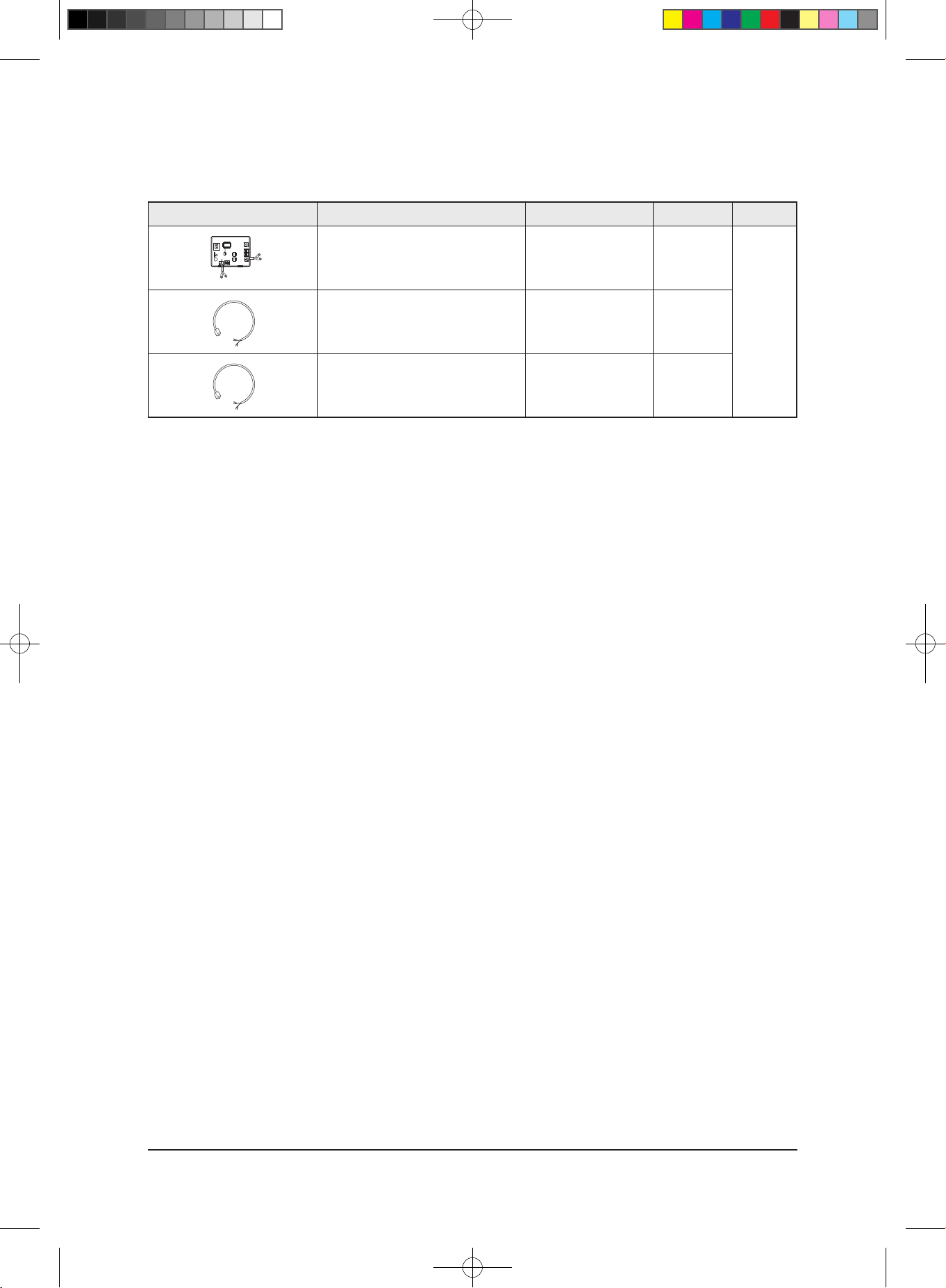
■ Transmitter
Item Descriptions Code-No. Q'TY Remark
Transmitter DB93-03374C
1
Transmitter power cable DB39-00378D
1
Transmitter communication cable DB39-00253D
1
Product Specifications
29347A(1)_1.indd 9 2008-01-23 ソタネト 1:40:11
Samsung Electronics
3. Alignment and Adjustments
3-1 Indoor Display Error and Check Method
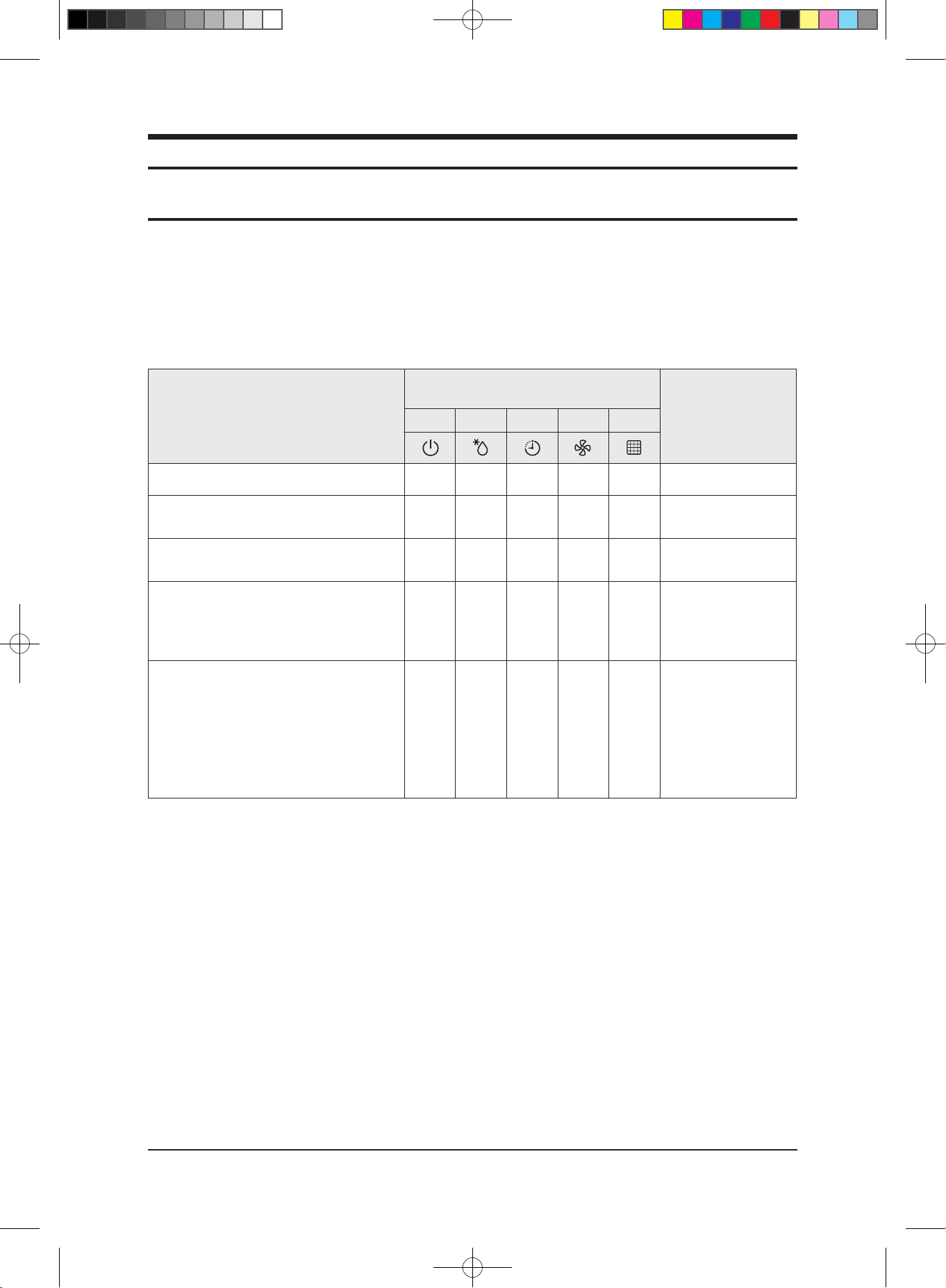
■ Error detection and reoperation
■ ● If error occurs during the operation, badness is indicated by LED flickering and all operation is stopped except LED.
■ ● When reoperating by remote control and switch determine the error mode after normal operation.
■ Indoor unit LED lamp display at error detecting
Abnormal conditions
LED lamp display
Remarks
Green Red Yellow Green Orange
Power reset
◑ X X X X
Error of temperature sensor
in the indoor unit (Open/Short)
X X ◑ X X
Error of heat exchanger sensor
in the indoor unit
◑ X ◑ X
Error of the outdoor temperature sensor
Error of the condensor temperature sensor
Error of the discharge temperature sensor
◑ X X ◑ X
Indoor and outdoor unit time out
Abnormal data reception more than 60 packet
Indoor unit is not connected
Communication error between the outdoor unit
Main-Inverter Micom(After 1 minute of Main-Inverter
detection)
X X ◑ ◑ X
1. Indoor unit error
(Display is unrelated
with operation)
2. Outdoor unit error
(Display is unrelated
with operation)
● : On, ◑ : Flickering, X: OFF
◆ If you turn off the air conditioner when the LED is flickering, the LED is also turned off.
3-1
29347A(1)_1.indd 10 2008-01-23 ソタネト 1:40:11
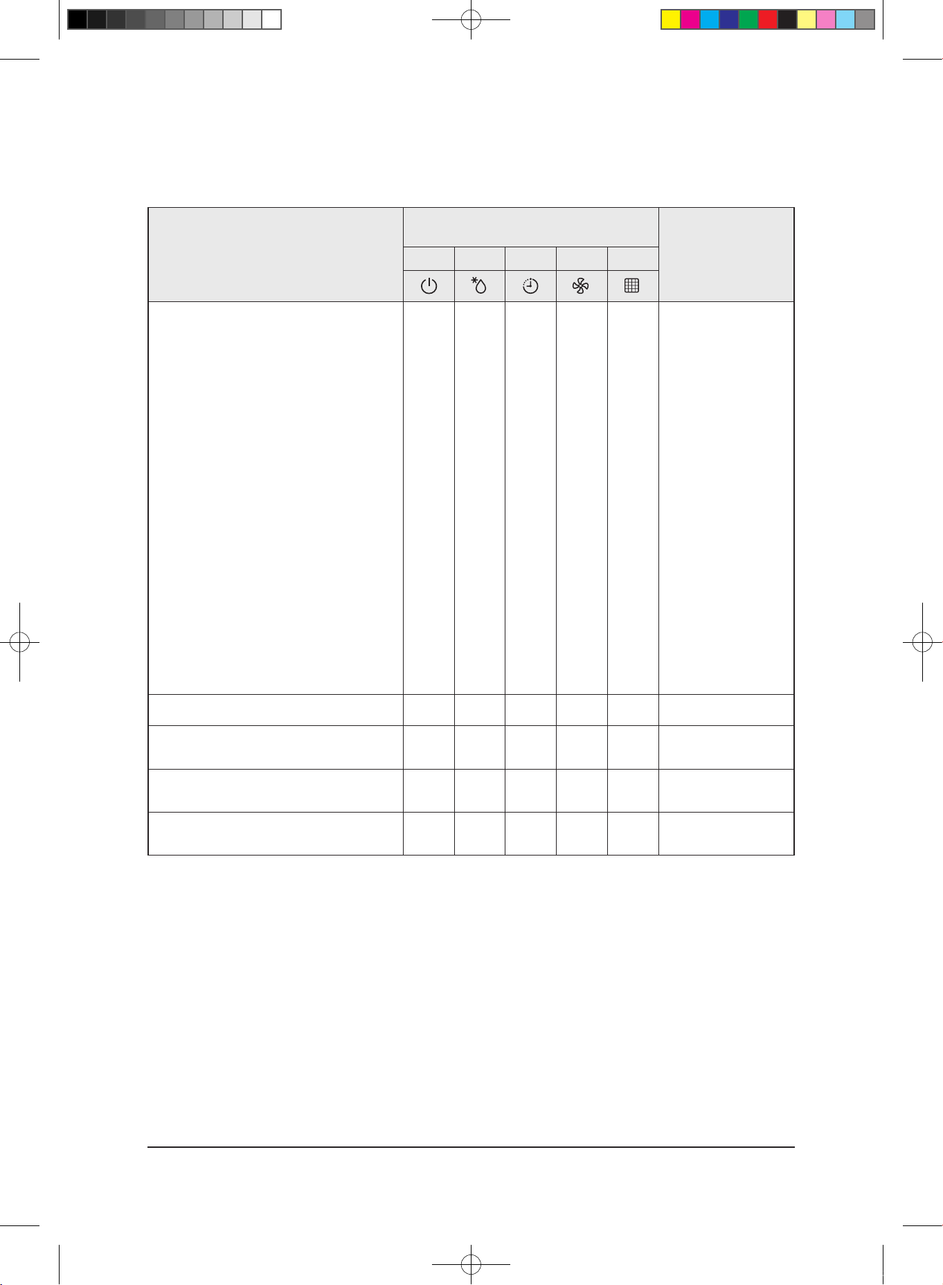
■ LED Display
Abnormal conditions
LED lamp display
Remarks
Green Red Yellow Green Orange
[Self diagnosis]Power voltage detection between
indoor and outdoor unit
communication cable
[Self diagnosis]Outdoor unit refrigerant leakage(Gas
leak)
[Self diagnosis]Outdoor fan restriction error
[Inverter]Inverter compressor operation failure
[Inverter] DC peak error
[Inverter]DC Link voltage 150V or less,
410V or more
[Inverter] Compressor rotation error
[Inverter]Electric current error
[Inverter]DC Link sensor error
[Inverter]EEPROM READ/WRITE error
[Inverter]Inverter zero crossing error
Setting the outdoor unit capacity option error
X X ◑ ◑ ◑
Detection of the float switch
X X X ◑ ◑
Error of setting option switches for optional
accessories
X X ◑ X ◑
EEPROM error
◑ X ◑ ◑ X
EEPROM option error
◑ ◑ ◑ ◑ ◑
● : On, ◑ : Flickering, X: OFF
◆ If you turn off the air conditioner when the LED is flickering, the LED is also turned off.
3-2Samsung Electronics
Alignment and Adjustments
29347A(1)_1.indd 11 2008-01-23 ソタネト 1:40:12
Samsung Electronics
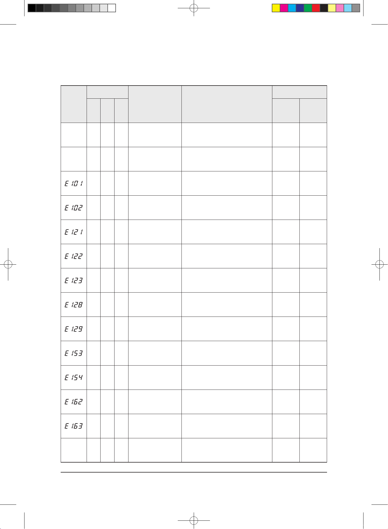
3-1-1 Outdoor Error Display and Check Method
3-3
Alignment and Adjustments
MAIN
7-Segment
Inverter LED
Content Measures
Product operation status in
case of error
Yellow Green Red
Number of
Times
Outdoor unit
compressor/
outdoor unit
fan
-
○ ○ ○
Power OFF/VDD NG
• Check the input power line(AC)
• Check the LED of Main PCB and Inverter PCB
- -
-
○ ◎ ●
Normal Operation
-
- -
○ ◎ ●
Indoor unit communication
error(1min.)
• Check the communication line for indoor units
• Check the power supply of the communication
phase(DC)
1 Time Operation-off
○ ◎ ●
Communication time-out
error(2min.)
• Check the communication line for indoor units
• Check the power supply of the communication
phase(DC)
1 Time Operation-off
○ ◎ ●
Indoor temperature sensor
• Check the temp. sensor of the indoor unit room
• Check the indoor PCB connector
1 Time Operation-off
○ ◎ ●
Indoor unit EVA IN sensor
• Check the indoor unit drainage pipe sensor
• Check the indoor PCB connector
1 Time Operation-off
○ ◎ ●
Indoor unit EVA OUT sensor
• Check the indoor unit drainage pipe sensor
• Check the indoor PCB connector
1 Time Operation-off
○ ◎ ●
Dismount of indoor unit
EVA IN sensor
• Check the drainage pipe has been dismounted
1 Time Operation-off
○ ◎ ●
Dismount of indoor unit
EVA OUT sensor
• Check the drainage pipe has been dismounted
1 Time Operation-off
○ ◎ ●
Secondary detection of
indoor floating switch
• Check the indoor unit's float sensor
• Check the indoor PCB connector
1 Time Operation-off
○ ◎ ●
Indoor fan error
• Check the indoor PCB connector
1 Time Operation-off
○ ◎ ●
Indoor eeprom error
• Check the EEPROM data
• Check the indoor's option
1 Time Operation-off
○ ◎ ●
Indoor eeprom option error
• Check the EEPROM data
• Check the indoor's option
1 Time Operation-off
-
● ● ●
POWER ON RESET(1SEC)
- - -
29347A(1)_1.indd 12 2008-01-23 ソタネト 1:40:12
Samsung Electronics
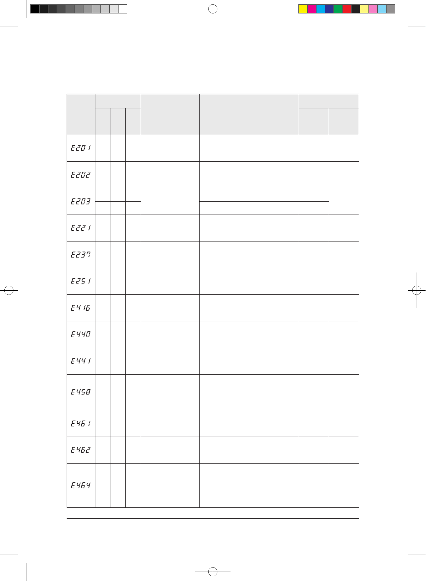
Outdoor Error Display and Check Method(cont.)
3-4
Alignment and Adjustments
MAIN
7-Segment
Inverter LED
Content Measures
Product operation status in
case of error
Yellow Green Red
Number of
Times
Outdoor unit
compressor/
outdoor unit
fan
○ ◎ ●
Indoor unit not connected
• Check the indoor unit connection
• Check the indoor unit number(multi only)
1 Time Operation-off
◎ ● ●
1min. Time out Comm.
(Display Board : Onboard :
Indoor
↔ Outdoor)
• Check the indoor unit connection
• Check the indoor unit option
1 Time Operation-off
○ ○ ●
Abnormal Serial
communication(Display
Board:Indoor ↔ Outdoor)
- -
-
○ ● ●
- -
◎ ○ ◎
Outdoor temp sensor error
(Dual/Single)
• Check the connection status of the sensor
• Check the sensor location
• Check the risistance values of sensor
1 Time Operation-off
◎ ● ◎
Cond temp sensor error
(Dual/Single)
• Check the connection status of the sensor
• Check the sensor location
• Check the risistance values of sensor
1 Time Operation-off
◎ ◎ ○
Discharge temp sensor error
(Dual/Single)
• Check the connection status of the sensor
• Check the sensor location
• Check the risistance values of sensor
1 Time Operation-off
◎ ○ ●
Discharge over temperature
(Dual/Single)
- 3 Times Operation-off
● ◎ ○
Operation condition
secession(HEATING)
• Check the operation status of operation mode
• Check the temp. sensor
1 Time Operation-off
Operation condition
secession(COOLING)
● ○ ○
Fan error
• Check the input power connection status
• Check the connection status between the motor
and PCB in outdoor unit
• Check the fuse of indoor/outdoor units
1 Time Operation-off
○ ◎ ○
Comp Starting error
• Check the connection status of the compressor
• Check the resistand between different phases in
compressor
5 Times Operation-off
● ◎ ●
I_Trip error / PFC Over cur
-
rent
• Check the input power
• Check the refrigerant is filled
• Check the outdoor fan operation normally
3 Times Operation-off
○ ○ ◎
IPM Over Current(O.C)
• Check the refrigerant is filled
• Check the connection status of compressor and
if it operates normally
• Check for any obstacles around indoor/outdoor
units
9 Times Operation-off
29347A(1)_1.indd 13 2008-01-23 ソタネト 1:40:12

Samsung Electronics
3-5
Alignment and Adjustments
MAIN
7-Segment
Inverter LED
Content Measures
Product operation status in
case of error
Yellow Green Red
Number of
Times
Outdoor unit
compressor/
outdoor unit
fan
◎ ● ○
Comp Vlimit error
• Check the connection status of compressor
• Check the resistance between different phases
in compressor
9 Times Operation-off
○ ● ◎
DC-Link voltage under/
over error
• Check the connection of input power
-
Restart(after
3min.)
● ○ ●
Comp rotation error
• Check the connection status of the compressor
• Check the resistance between different phases
in compressor
3 Times Operation-off
◎ ◎ ●
Current sensor error
• Check the PCB operates normally
1 Time Operation-off
● ◎ ◎
DC-Link valtage sensor error
• Check the connection of input power
1 Time Operation-off
● ○ ◎
OTP error
• Check the PCB operates normally
1 Time Operation-off
● ● ◎
AC Line Zero Cross Signal
out
• Check the connection of input power
1 Time Operation-off
○ ● ○
Comp Lock error
• Check the connection status of the compressor
• Check the resistance between different phases
in compressor
3 Times Operation-off
● ○ ○
Fan error(two fan outdoor)
• Check the input power connection status
• Check the connection status between the
motor and PCB in outdoor unit
• Check the fuse of indoor/outdoor units
1 Time Operation-off
● ● ○
GAS Leak error(Dual/Single)
• Check refrigerant is filled
• Check the indoor EVA sensor
3 Times Operation-off
◎ ○ ○
Capacity miss match
• Check the indoor unit's option code
• Check the capacity of indoor unit's and
outdoor unit's
1 Time Operation-off
-
○ ◎ ◎
Test Operation at Cooling
Mode
- - -
-
◎ ◎ ◎
Test Operation at Heating
Mode
- - -
Outdoor Error Display and Check Method(cont.)
29347A(1)_1.indd 14 2008-01-23 ソタネト 1:40:12
Samsung Electronics
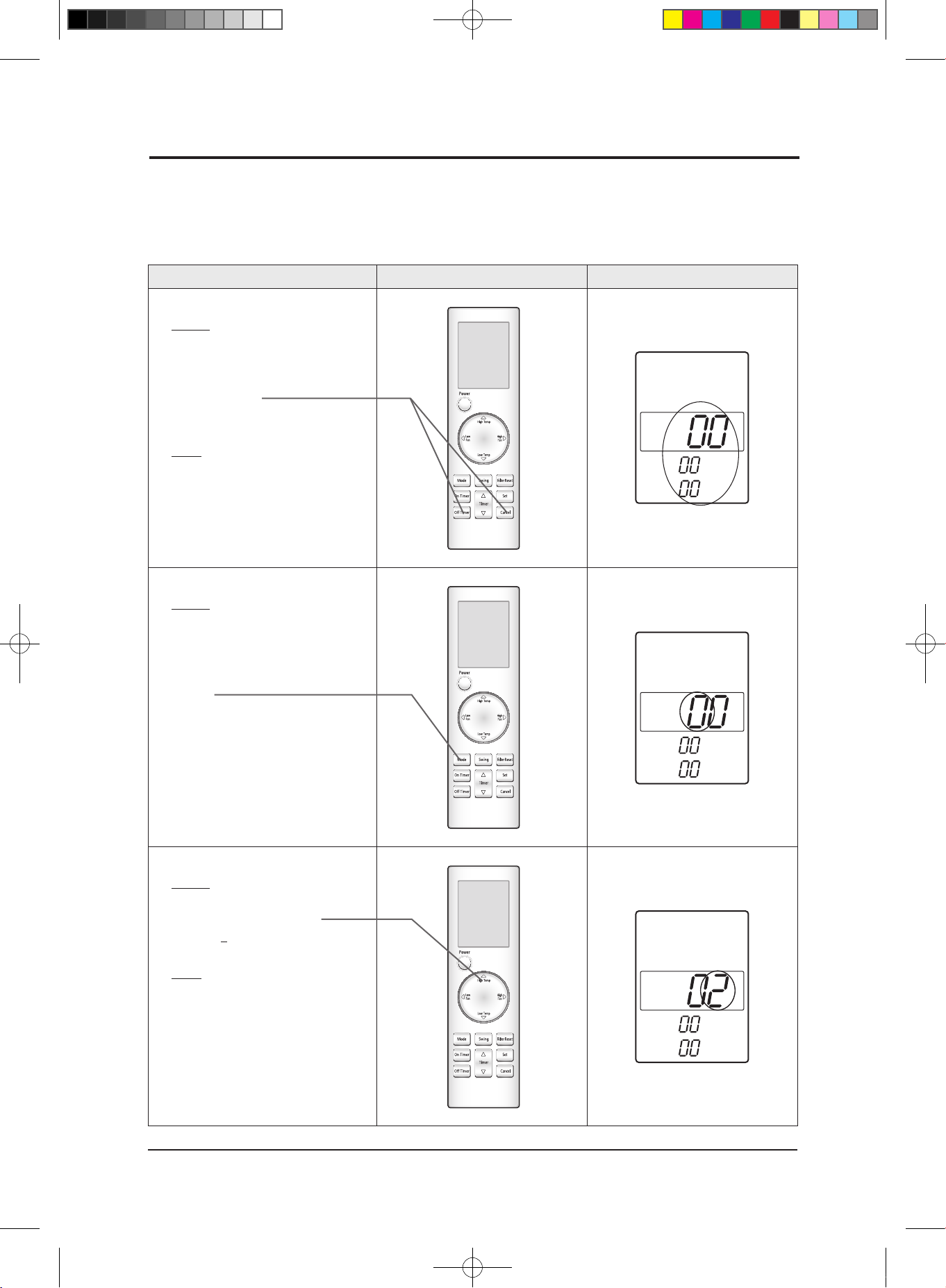
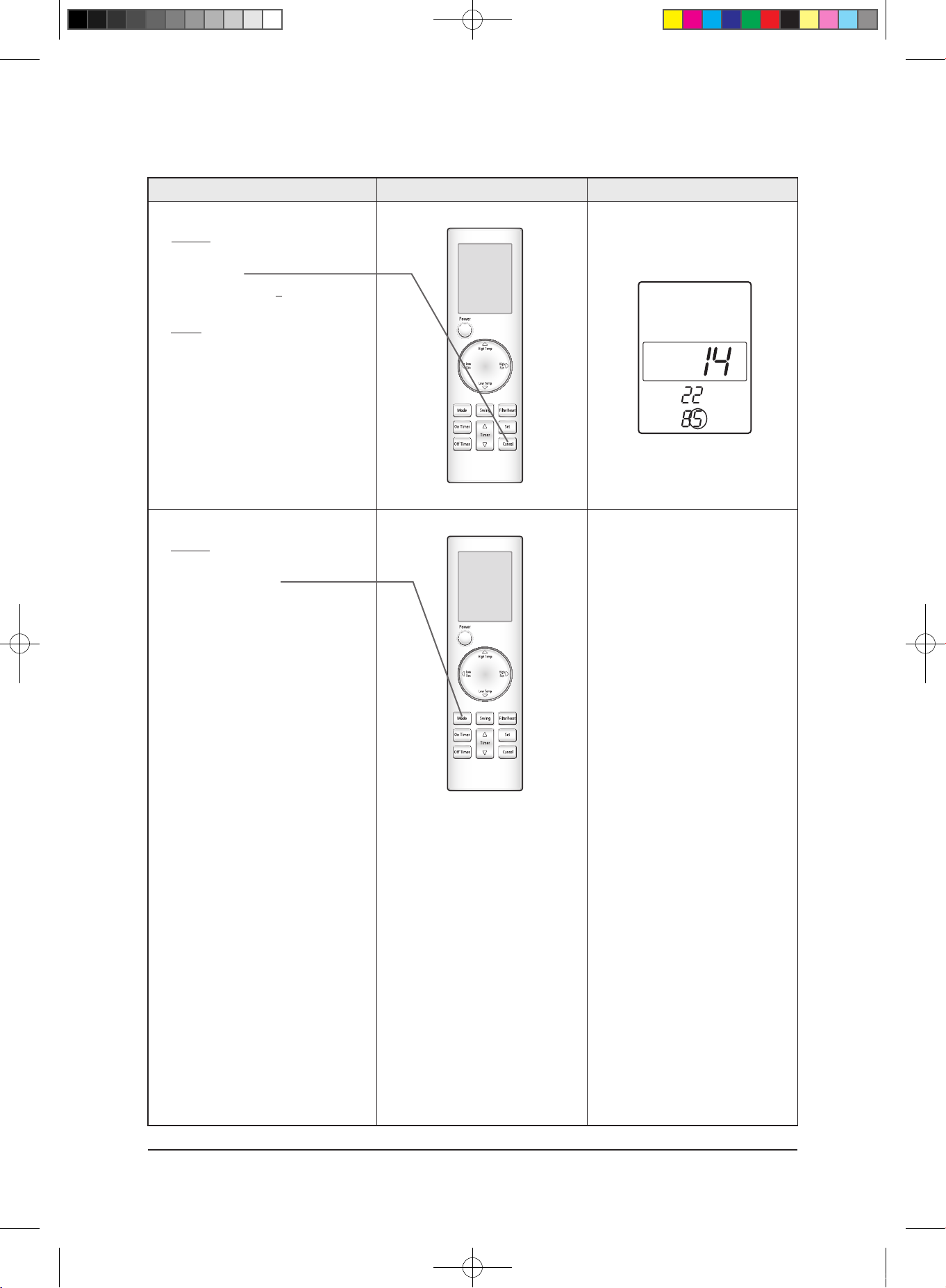
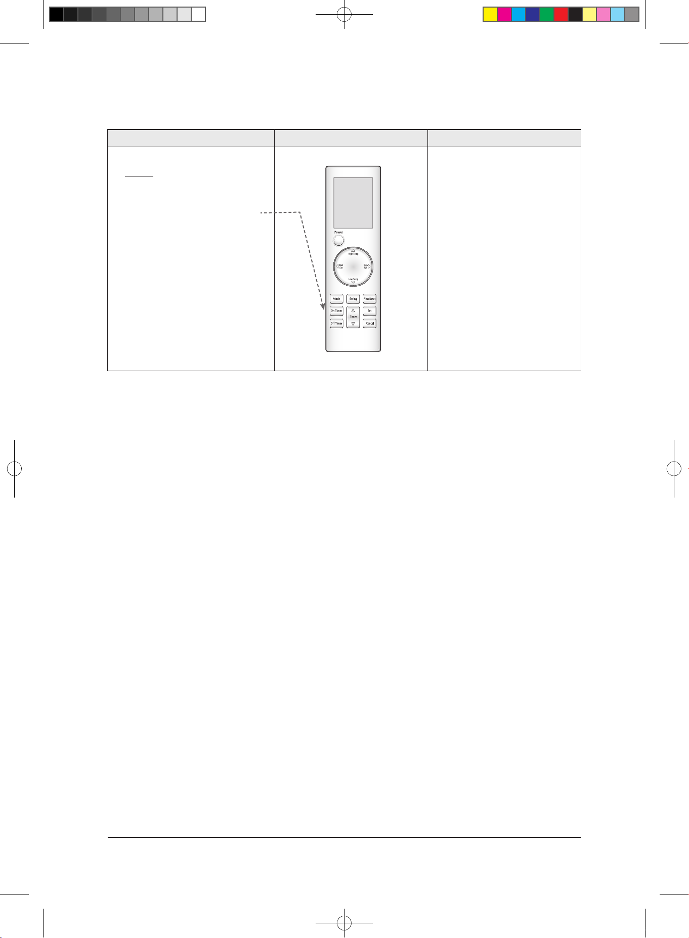
Operation method Applicable button Indicating state
✳ Step 1
✳ Method)
✳ ① Remove the battery of remote
controller.
✳ ② Push the Off Timer and Cancel button
simultaneously.
✳ ③Insert the battery.
✳ Result)
✳ When the display of remote
✳ controller is indicated as shown
✳ in the right, then go to the step 2.
✳ Step 2
✳ Method)
✳ If the first digit of remote
controller shows "0", go to the step 3.
• If it shows 1, press the Mode button one
time to change it into 0 and then go to
step 3.
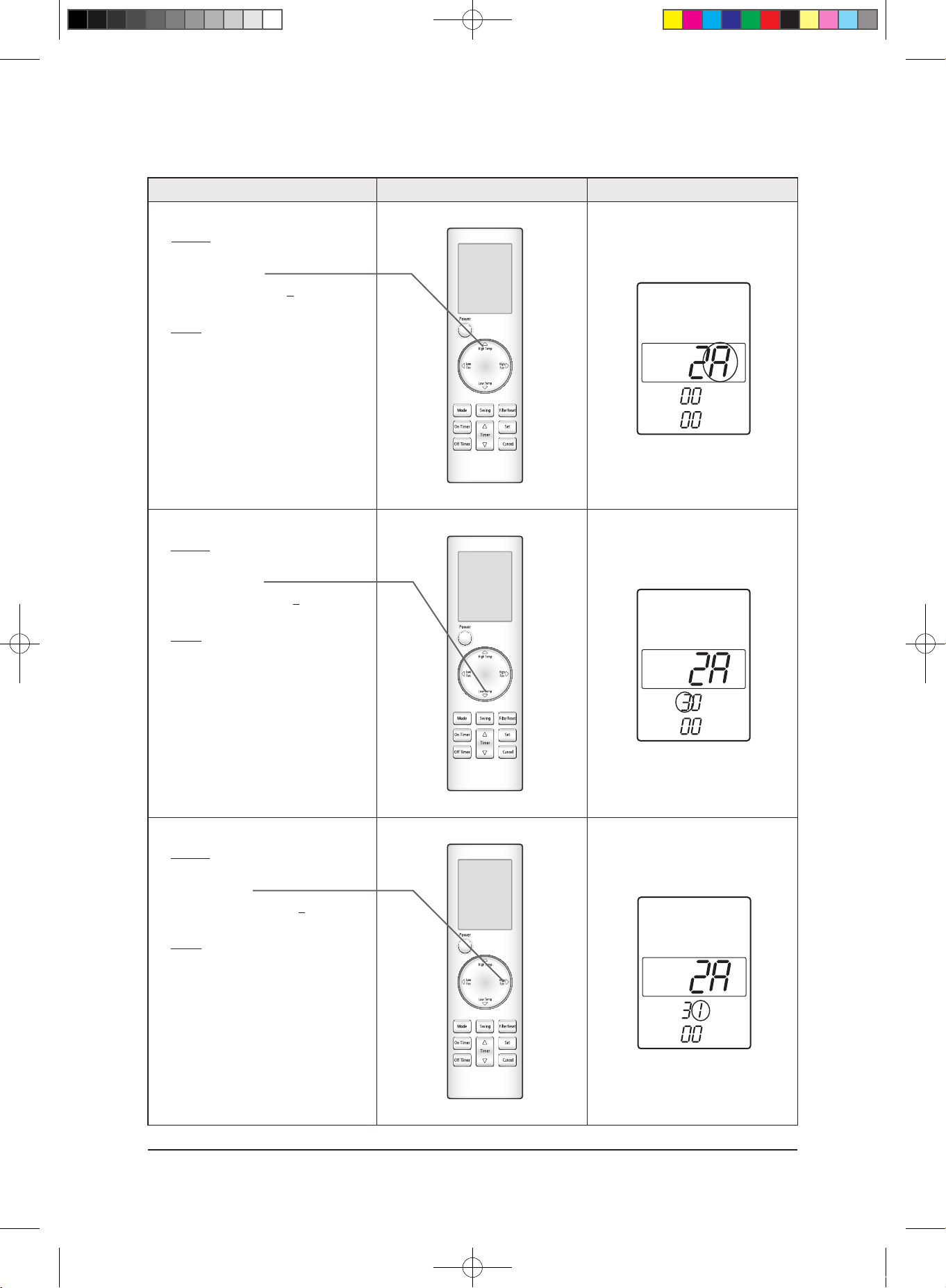
✳ Step 3
✳ Method)
✳ Input the second digit of option code by
pressing the High Temp button.
example) 0
21E311422852A311439421F
✳ Result)
✳ If 2 is displayed, go to the step 4
(whenever pressing the button, 1~9,
A,B,C,D,E,F are lit in order.)
3-2 Setting Option Setup Method
3-2-1 PCB option code input method(example : 021E31-142285-2A3114-39421F)
Be sure to input the option code suitable for the indoor unit by use of wireless remote controller after replacing the PCB of indoor unit.
Follow to do the following 27 steps sequentially.
3-6
29347A(1)_1.indd 15 2008-01-23 ソタネト 1:40:13

Samsung Electronics
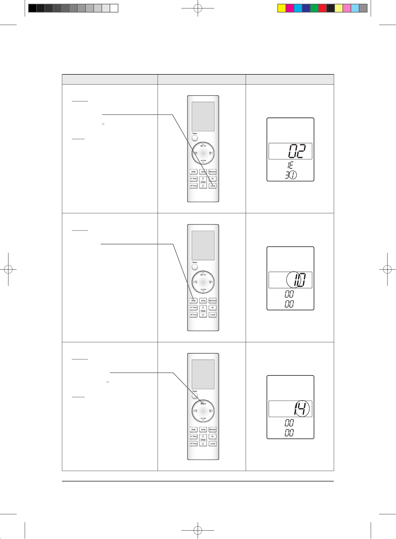
Operation method Applicable button Indicating state
✳ Step 4
Method)
Input the third digit of option code by
pressing the Low Temp button.
example) 02
1E311422852A311439421F
Result)
If 1 is displayed, go to the step 5.
✳ Step 5
✳ Method)
Input the fourth digit of option code by
pressing the High Fan button.
example) 021
E311422852A311439421F
Result)
If E displays, go to step 6.
✳ Step 6
✳ Method)
Input the fifth digit of option code by
pressing the On Timer button.
example) 021E
311422852A311439421F
Result)
If 3 displays, go to step 7.
SEG5
3-7
Alignment and Adjustments
29347A(1)_1.indd 16 2008-01-23 ソタネト 1:40:15
Samsung Electronics
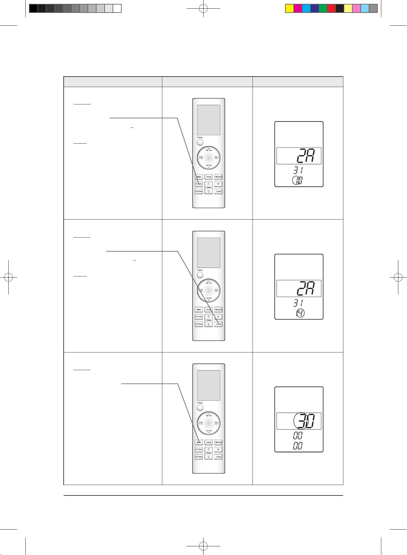
Operation method Applicable button Indicating state
✳ Step 7
Method)
Input the sixth digit by pressing the
Cancel button.
example) 021E3
11422852A311439421F
Result)
If 1 displays, go to step 8.
✳ Step 8
✳ Method)
After completion up to step 7, pressing
Mode button.
① 1~7 steps are saved internally.
② If the first number is 1 at the time,
it is correct. So go to step 9.
• If wanting to see the screen
of 2~7 steps, press the mode button
repeatedly to make the first digit 0.
✳ Step 9
✳ Method)
Input the eighth digit by pressing the
High Temp button.
example) 021E311
422852A311439421F
Result)
If 4 displays, go to step 10.
3-8
Alignment and Adjustments
29347A(1)_1.indd 17 2008-01-23 ソタネト 1:40:17

Samsung Electronics
Operation method Applicable button Indicating state
✳ Step 10
Method)
✳ Input the ninth digit by pressing the
Low Temp button.
example) 021E3114
22852A311439421F
✳ Result)
✳ If 2 displays, go to step 11.
✳ Step 11
✳ Method)
✳ Input the tenth digit by pressing the High
Fan button.
example) 021E31142
2852A311439421F
✳ Result)
✳ If 2 displays, go to step 12.
✳ Step 12
✳ Method)
✳ Input the 11st digit by pressing the
On Timer button.
example) 021E311422
852A311439421F
✳ Result)
✳ If 8 displays, go to step 13.
3-9
Alignment and Adjustments
29347A(1)_1.indd 18 2008-01-23 ソタネト 1:40:19
Samsung Electronics
Operation method Applicable button Indicating state
✳ Step 13
Method)
✳ Input the 12th digit by pressing the
Cancel button.
example) 021E3114228
52A311439421F
✳ Result)
✳ If 5 displays, go to step 14.
Step 14
✳ Method)
✳ After completion up to step 13,
pressing Mode button.
■ ① Previous steps are saved internally.
■ ② If the first number is 2 at the time, it is
correct. So go to step 15.
✳ • If wanting to see previous screen, press
the mode button repeatedly to make the
first digit to with digit.
■ Error
■① If the On/Off, Timer and Fan
indicator is flickering, the wrong option
code is input. Put off the power of
indoor unit and turn it on again and
then input the option code again.
If the same error occurs, it is the
EEPROM is defective or not
inserted. Replace the PCB.
■② If all of On/Off, Timer, Fan and Filter
Sign indicator are flickering along
with the "Tiriring" sound, there is option
code already input which are different
from the current ones.
Check the option code and press the
button again if correct. Option code will
be input.(Check the option code
correctly. At the time, if the same error
continues to occur, the option code is
out of input range.
Check the option code again and
repeat the step 1~14.
3-10
Alignment and Adjustments
29347A(1)_1.indd 19 2008-01-23 ソタネト 1:40:22
Samsung Electronics
Operation method Applicable button Indicating state
✳ Step 15
Method)
✳ Input the 14th digit by pressing the
High Temp button.
example) 021E311422852
A311439421F
✳ Result)
✳ If A displays, go to step 16.
✳ Step 16
✳ Method)
✳ Input the 15th digit by pressing the
Low Temp button.
example) 021E311422852A
311439421F
✳ Result)
✳ If 3 displays, go to step 17.
✳ Step 17
✳ Method)
✳ Input the 16th digit by pressing the
High Fan button.
example) 021E311422852A3
11439421F
✳ Result)
✳ If 1 displays, go to step 18.
3-11
Alignment and Adjustments
29347A(1)_1.indd 20 2008-01-23 ソタネト 1:40:24
Samsung Electronics
Operation method Applicable button Indicating state
✳ Step 18
Method)
✳ Input the 17th digit by pressing the
On Timer button.
example) 021E311422852A31
1439421F
✳ Result)
✳ If 1 displays, go to step 19.
✳ Step 19
✳ Method)
✳ Input the 18th digit by pressing the
Cancel button.
example) 021E311422852A311
439421F
✳ Result)
✳ If 4 displays, go to step 20.
✳ Step 20
✳ Method)
✳ After completion up to step 20,
pressing Mode button.
■ ① Previous steps are saved internally.
■ ② If the first number is 3 of the time,
it is correct. so go to step 22.
• If wanting to see previous screen, press the
mode button repeatedly to make the first
digit to with digit.
3-12
Alignment and Adjustments
29347A(1)_1.indd 21 2008-01-23 ソタネト 1:40:27

Samsung Electronics
Operation method Applicable button Indicating state
✳ Step 21
Method)
✳ Input the 20th digit by pressing the
High Temp button.
example) 021E311422852A31143
9421F
✳ Result)
✳ If 9 displays, go to step 22.
✳ Step 22
✳ Method)
✳ Input the 21th digit by pressing the
Low Temp button.
example) 021E311422852A311439
421F
✳ Result)
✳ If 4 displays, go to step 23.
✳ Step 23
✳ Method)
✳ Input the 22th digit by pressing the
High Fan button.
example) 021E311422852A3114394
21F
✳ Result)
✳ If 2 displays, go to step 24.
3-13
Alignment and Adjustments
29347A(1)_1.indd 22 2008-01-23 ソタネト 1:40:29
Samsung Electronics
Operation method Applicable button Indicating state
✳ Step 24
Method)
Input the 23th digit by pressing the
On Timer button.
example) 021E311422852A31143942
1F
✳ Result)
✳ If 1 displays, go to step 25.
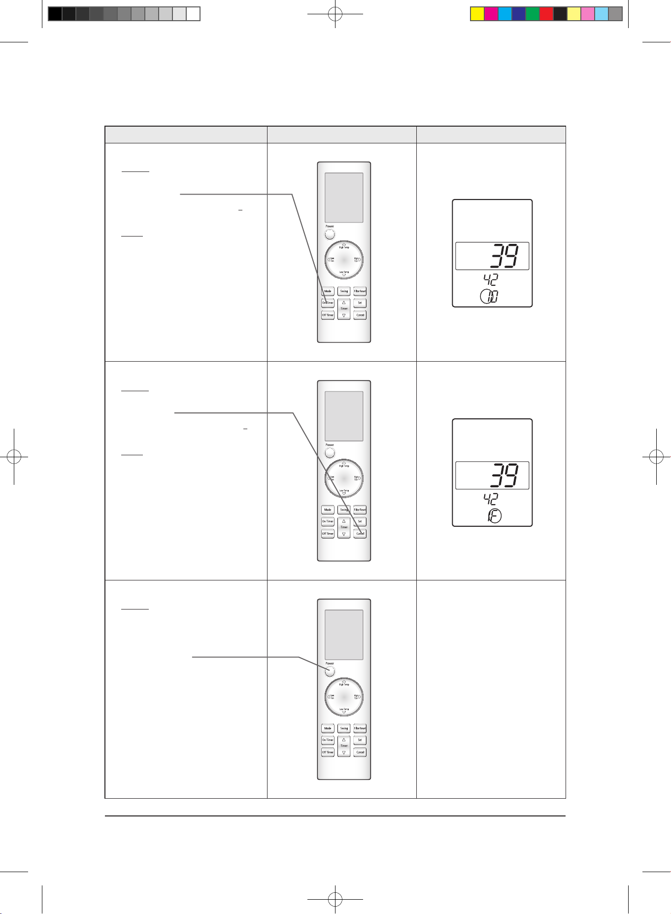
✳ Step 25
✳ Method)
✳ Input the 24th digit by pressing the
Cancel button.
example) 021E311422852A311439421
F
✳ Result)
✳ If F displays, go to step 26.
✳ Step 26
✳ Method)
✳ Turn the remote controller toward the
indoor unit and press the Power button,
and if the "Ting" or "Tiriring" sounds, the
input of option is completed.
✳ • If error displays, solve the
problem with reference to the
right side.
■ Error
■ ① If the On/Off, Timer and Fan
indicator is flickering, the wrong option
code is input. Put off the power of
indoor unit and turn it on again and
then input the option code again.
If the same error occurs, it is the
EEPROM is defective or not
inserted. Replace the PCB.
■ ② If all of On/Off, Timer, Fan and Filter
Sign indicator are flickering along with
the "Tiriring" sound, there is option
code already input which are different
from the current ones.
Check the option code and press the
button again if correct. Option code will
be input.(Check the option code
correctly. At the time, if the same error
continues to occur, the option code is
out of input range.
Check the option code again and repeat
the step 1~26.
3-14
Alignment and Adjustments
29347A(1)_1.indd 23 2008-01-23 ソタネト 1:40:31
Samsung Electronics
Operation method Applicable button Indicating state
✳ Step 27
Method)
If the steps 1 to 26 are completed, remove
the battery and insert it again to return to
the original display of remote controller.
(Operation mode/SET TEMP.
/fan speed displays.)
■ Error
① If the On/Off, Timer and Fan
indicator is flickering, the wrong option
code is input. Put off the power of
indoor unit and turn it on again and
then input the option code again.
If the same error occurs, it is the
EEPROM is defective or not inserted.
Replace the PCB.
② If all of On/Off, Timer, Fan and Filter
Sign indicator are flickering along with
the "Tiriring" sound, there is option
code already input which are different
from the current ones.
Check the option code and press the
button again if correct. Option code will
be input.(Check the option code
correctly. At the time, if the same error
continues to occur, the option code is
out of input range.
Check the option code again and repeat
the step 1~26.
rear side
3-15
Alignment and Adjustments
29347A(1)_1.indd 24 2008-01-23 ソタネト 1:40:33
Samsung Electronics
Alignment and Adjustments
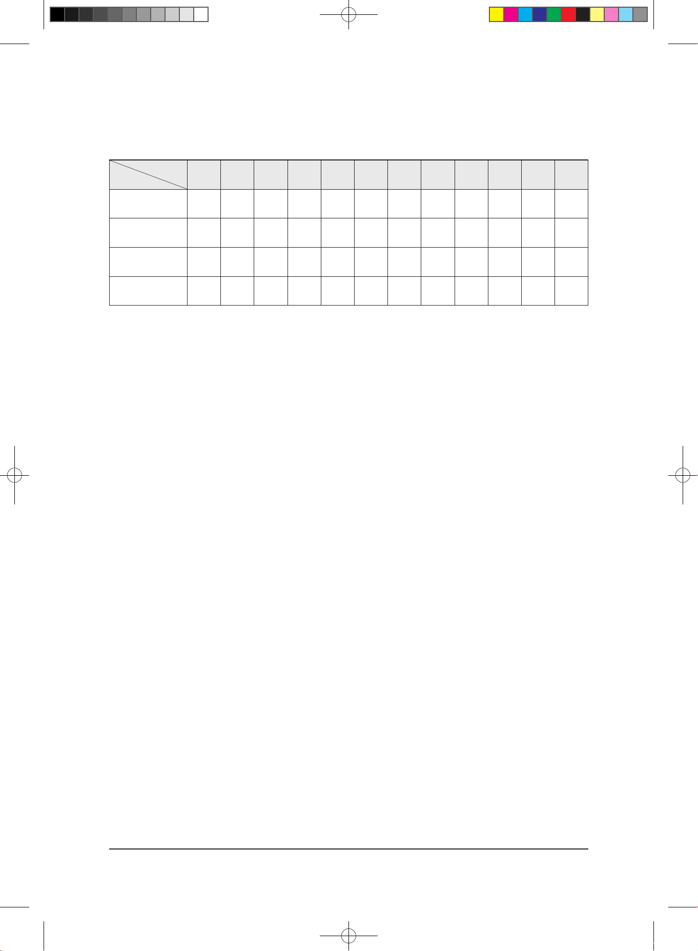
3-2-2 Option Items
SEG1 SEG2 SEG3 SEG4 SEG5 SEG6 SEG7 SEG8 SEG9 SEG10 SEG11 SEG12
TH026EAV1 0 4 5 7 7 1 1 3 8 3 d 9
TH035EAV1
0 4 5 7 7 3 1 5 8 1 0 9
TH052EAV1
0 4 8 7 7 4 1 9 8 0 8 0
TH060EAV1
0 4 5 7 7 4 1 b 8 0 d 5
MODEL
REMOCON
3-16
29347A(1)_1.indd 25 2008-01-23 ソタネト 1:40:34
 Loading...