

Page 1
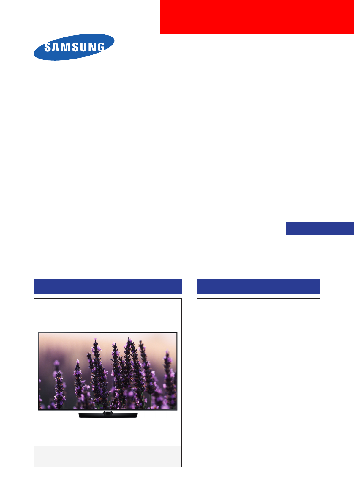
LED TV
Chassis : U8DC
Model : UE32H5500AW
UE40H5500AW
UE48H5500AW
UE50H5500AW
SERVICE
LED TV Contents
1. Precautions
2. Product specications
3. Disassembly and Reassembly
4. Troubleshooting
5. Wiring Diagram
Manual
UE**H5500AW
Page 2

Contents
1. Precautions ...................................................................................................................1-1
1-1. Safety Precautions ..............................................................................................................1-1
1-1-1. Warnings ...................................................................................................................1-1
1-1-2. Servicing the LED TV ...............................................................................................1-1
1-1-3. Fire and Shock Hazard .............................................................................................1-1
1-1-4. Product Safety Notices .............................................................................................1-2
1-2. Servicing Precautions ..........................................................................................................1-3
1-2-1. General Servicing Precautions ................................................................................. 1-3
1-3. Static Electricity Precautions ...............................................................................................1-4
1-4. Installation Precautions .......................................................................................................1-5
2. Product Specications.................................................................................................2-1
2-1. Product information .............................................................................................................2-1
2-2. Product specication ...........................................................................................................2-2
2-2-1. Detailed Specications ............................................................................................. 2-2
2-2-2. Specications ...........................................................................................................2-6
2-3. Accessories ........................................................................................................................2-7
3. Disassembly and Reassembly ....................................................................................3-1
3-1. Disassembly and Reassembly ............................................................................................3-1
4. Troubleshooting ...........................................................................................................4-1
4-1. Troubleshooting ...................................................................................................................4-1
4-1-1. Previous Check ........................................................................................................4-1
4-2. How to Check Fault Symptom .............................................................................................4-3
4-2-1. NO Power .................................................................................................................4-3
4-3. Factory Mode Adjustments ..................................................................................................4-6
4-3-1. Detail Factory Option ................................................................................................4-6
4-3-2. Entering Factory Mode ............................................................................................. 4-7
4-3-3. Factory Data .............................................................................................................4-8
4-4. White Balance ...................................................................................................................4-23
4-4-1. Calibration ..............................................................................................................4-23
4-4-2. Service Adjustment ................................................................................................. 4-23
4-4-3. Adjustment .............................................................................................................. 4-25
4-5. Software Upgrade ..............................................................................................................4-26
4-5-1. By USB ...................................................................................................................4-26
4-5-2. By Online ................................................................................................................4-26
4-5-3. Alternative Software (Backup) ................................................................................ 4-26
4-6. The Dimension of H55** Models .......................................................................................4-27
5. Wiring Diagram .............................................................................................................5-1
5-1. Wiring Diagram ....................................................................................................................5-1
5-2. Connector ............................................................................................................................5-6
5-3. Connector Functions ...........................................................................................................5-9
Page 3
This Service Manual is a property of Samsung Electronics Co.,Ltd.
Any unauthorized use of Manual can be punished under applicable
International and/or domestic law.
© 2014 Samsung Electronics Co.,Ltd.
All rights reserved.
Printed in Korea
Page 4
1. Precautions
1. Precautions
1-1. Safety Precautions
Follow these safety, servicing and ESD precautions to prevent damage and to protect against potential hazards such as
electrical shock.
1-1-1. Warnings
For continued safety, do not attempt to modify the circuit board.
WARNING
1-1-2. Servicing the LED TV
When servicing the LED TV, Disconnect the AC line cord from the AC outlet.1.
It is essential that service technicians have an accurate voltage meter available at all times. Check the calibration of this 2.
meter periodically.
1-1-3. Fire and Shock Hazard
Before returning the monitor to the user, perform the following safety checks:
Inspect each lead dress to make certain that the leads are not pinched or that hardware is not lodged between the 1.
chassis and other metal parts in the monitor.
Inspect all protective devices such as nonmetallic control knobs, insulating materials, cabinet backs, adjustment and 2.
compartment covers or shields, isolation resistorcapacitor networks, mechanical insulators, etc.
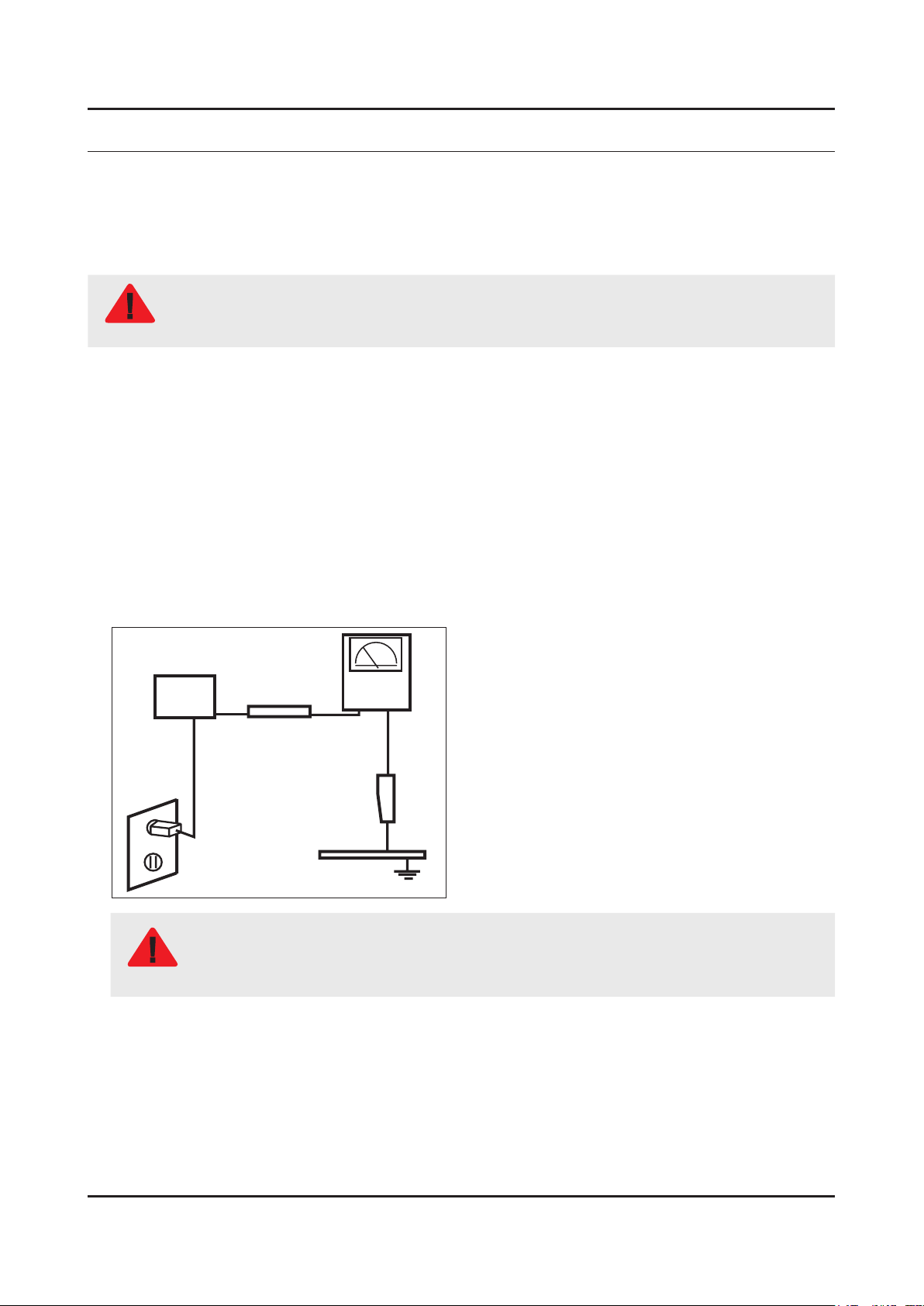
Leakage Current Hot Check:3.
Disconnect the AC power and DC power jack before servicing.
(READING SHOULD)
DEVICE
UNDER
TEST
ALSO TEST WITH
PLUG REVERSED
(USING AC ADAPTER
PLUG AS REQUIRED)
NOT BE ABOVE 0.5mA
2-WIRE CORD
TEST ALL
EXPOSED METAL
SURFACES
LEAKAGE
CURRENT
TESTER
EARTH
GROUND
Do not use an isolation transformer during this test.
Use a leakage current tester or a metering system that complies with American National Standards
WARNING
Institute (ANSI C101.1, Leakage Current for Appliances), and Underwriters Laboratories (UL
Publication UL1410, 59.7).
With the unit completely reassembled, plug the AC line cord directly into a 120V AC outlet. With the unit’s AC switch rst 4.
in the ON position and then OFF, measure the current between a known earth ground (metal water pipe, conduit, etc.)
and all exposed metal parts, including: metal cabinets, screwheads and control shafts.
The current measured should not exceed 0.5 milliamp.
Reverse the power-plug prongs in the AC outlet and repeat the test.
1-1
Page 5

1-2
1. Precautions
1-1-4. Product Safety Notices
Some electrical and mechanical parts have special safetyrelated characteristics which are often not evident from visual
inspection. The protection they give may not be obtained by replacing them with components rated for higher voltage,
wattage, etc. Parts that have special safety characteristics are identied by on schematics and parts lists. A substitute
replacement that does not have the same safety characteristics as the recommended replacement part might create
shock, re and/or other hazards. Product safety is under review continuously and new instructions are issued whenever
appropriate.
Page 6
1-3
1. Precautions
1-2. Servicing Precautions
An electrolytic capacitor installed with the wrong polarity might explode.
WARNING
Before servicing units covered by this service manual, read and follow the Safety Precautions section of
CAUTION
NOTE
1-2-1. General Servicing Precautions
Always unplug the unit’s AC power cord from the AC power source and disconnect the DC Power Jack before 1.
attempting to: (a) remove or reinstall any component or assembly, (b) disconnect PCB plugs or connectors, (c) connect
a test component in parallel with an electrolytic capacitor.
Some components are raised above the printed circuit board for safety. An insulation tube or tape is sometimes used. 2.
The internal wiring is sometimes clamped to prevent contact with thermally hot components. Reinstall all such elements
to their original position.
After servicing, always check that the screws, components and wiring have been correctly reinstalled. Make sure that 3.
the area around the serviced part has not been damaged.
Check the insulation between the blades of the AC plug and accessible conductive parts (examples: metal panels, input 4.
terminals and earphone jacks).
Insulation Checking Procedure: Disconnect the power cord from the AC source and turn the power switch ON. Connect 5.
an insulation resistance meter (500 V) to theblades of the AC plug. The insulation resistance between each blade of the
AC plug and accessible conductive parts (see above) should be greater than 1 megohm.
Always connect a test instrument’s ground lead to the instrument chassis ground before connecting the positive lead; 6.
always remove the instrument’s ground lead last.
this manual.
If unforeseen circumstances create conict between the following servicing precautions and any of the
safety precautions, always follow the safety precautions.
Page 7
1-4
1. Precautions
1-3. Static Electricity Precautions
Some semiconductor (solid state) devices can be easily damaged by static electricity. Such components are commonly
called Electrostatically Sensitive Devices (ESD). Examples of typical ESD are integrated circuits and some eld-effect
transistors. The following techniques will reduce the incidence of component damage caused by static electricity.
Immediately before handling any semiconductor components or assemblies, drain the electrostatic charge from your 1.
body by touching a known earth ground. Alternatively, wear a discharging wrist-strap device. To avoid a shock hazard,
be sure to remove the wrist strap before applying power to the monitor.
After removing an ESD-equipped assembly, place it on a conductive surface such as aluminum foil to prevent 2.
accumulation of an electrostatic charge.
Do not use freon-propelled chemicals. These can generate electrical charges sufcient to damage ESDs.3.
Use only a grounded-tip soldering iron to solder or desolder ESDs.4.
Use only an anti-static solder removal device. Some solder removal devices not classied as “anti-static” can generate 5.
electrical charges sufcient to damage ESDs.
Do not remove a replacement ESD from its protective package until you are ready to install it. Most replacement ESDs 6.
are packaged with leads that are electrically shorted together by conductive foam, aluminum foil or other conductive
materials.
Immediately before removing the protective material from the leads of a replacement ESD, touch the protective material 7.
to the chassis or circuit assembly into which the device will be installed.
Be sure no power is applied to the chassis or circuit and observe all other safety precautions.
CAUTION
Minimize body motions when handling unpackaged replacement ESDs. Motions such as brushing clothes together, or 8.
lifting your foot from a carpeted oor can generate enough static electricity to damage an ESD.
Page 8

1-5
1. Precautions
1-4. Installation Precautions
For safety reasons, more than a people are required for carrying the product.1.
Keep the power cord away from any heat emitting devices, as a melted covering may cause re or electric shock.2.
Do not place the product in areas with poor ventilation such as a bookshelf or closet. The increased internal temperature 3.
may cause re.
Bend the external antenna cable when connecting it to the product. This is a measure to protect it from being exposed 4.
to moisture. Otherwise, it may cause a re or electric shock.
Make sure to turn the power off and unplug the power cord from the outlet before repositioning the product. Also check 5.
the antenna cable or the external connectors if they are fully unplugged. Damage to the cord may cause re or electric
shock.
Keep the antenna far away from any high-voltage cables and install it rmly. Contact with the highvoltage cable or the 6.
antenna falling over may cause re or electric shock.
When installing the product, leave enough space (0.4m) between the product and the wall for ventilation purposes. 7.
A rise in temperature within the product may cause re.
If an equipment is provided with a replaceable battery, and if replacement by an incorrect type could result in an 8.
explosion (for example, with some lithium batteries), the following applies:
Risk of explosion if battery is replaced by an incorrect type dispose of used batteries according to •
the instructions.
Do not dispose of batteries in a re.•
Do not short circuit, disassemble or overheat the batteries.•
CAUTION
Danger of explosion if battery is incorrectly replaced. Replace only with the same or equivalent •
type.
Do not be exposed to excessive heat such as sunshine, re or the like.•
Page 9
2. Product Specications
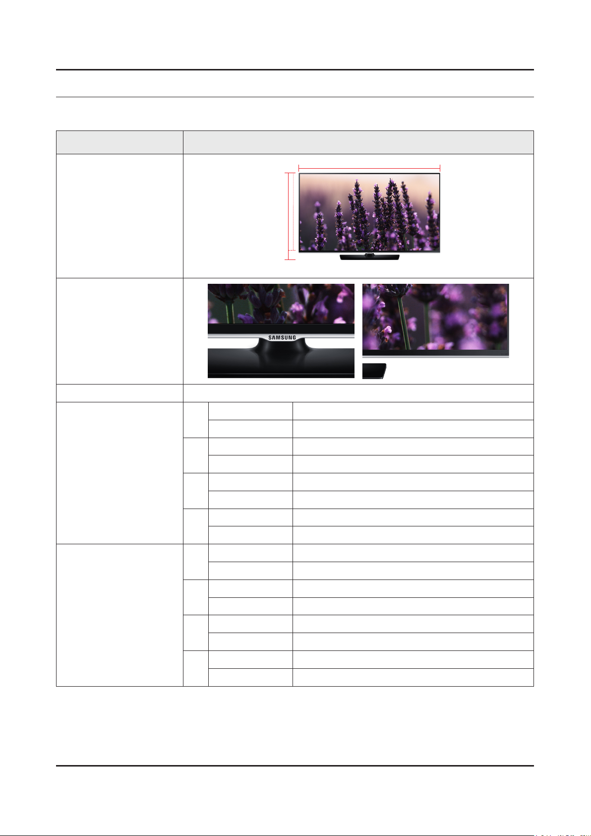
2-1. Product information
Model UE**H5500AW
2. Product specications
W
Front View
Detail View
Front Color Black
32"
40"
Dimensions
(W x H x D)
48"
With Stand 721.4 x 465.1 x 163.4 mm / 28.4 x 18.3 x 6.4 inches
Without Stand 721.4 x 428.5 x 64.9 mm / 28.4 x 16.9 x 2.6 inches
With Stand 906.6 x 578.2 x 196.4 mm / 35.7 x 22.8 x 7.7 inches
Without Stand 906.6 x 532.9 x 65.1 mm / 35.7 x 21.0 x 2.6 inches
With Stand 1075.1 x 673.8 x 203.9 mm / 42.3 x 26.5 x 8.0 inches
Without Stand 1075.1 x 627.6 x 65.5 mm / 42.3 x 24.7 x 2.6 inches
H
* W : Width H : High D : Depth
Weight
50"
With Stand 1116.8 x 696.4 x 203.9 mm / 44.0 x 27.4 x 8.0 inches
Without Stand 1116.8 x 651.1 x 65.7 mm / 44.0 x 25.6 x 2.6 inches
With Stand 5.3 kg / 11.6 lbs
32"
Without Stand 4.9 kg / 10.8 lbs
With Stand 8.6 kg / 19.0 lbs
40"
Without Stand 7.7 kg / 17.0 lbs
With Stand 12.4 kg / 27.3 lbs
48"
Without Stand 11.1 kg / 24.5 lbs
With Stand 13.7 kg / 30.2 lbs
50"
Without Stand 13 kg / 28.7 lbs
2-1
Page 10
2-2
2. Product specications
2-2. Product specication
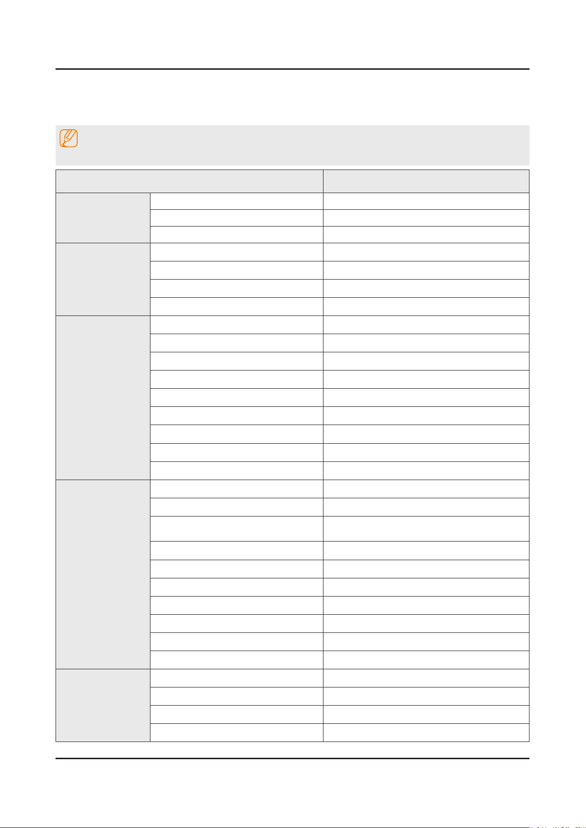
2-2-1. Detailed Specications
NOTE
Design and specications are subject to change without prior notice.
Item UE**H5500AWXXH
General Information
Display
Video
Audio
Product LED
Series 5
Country HUNGARY
Screen Size 32'/40"/48'/50"
Resolution 1,920 x 1,080
Ultra Clear Panel N/A
Screen Curvature No
Picture Engine HyperReal Engine
Clear Motion Rate 100
Micro Dimming N/A
Precision Black (Local Dimming) N/A
Wide Color Enhancer (Plus) Yes
Wide Color Gamut N/A
Color Accuracy N/A
Auto Depth Enhancer N/A
Film Mode Yes
Dolby MS10 / MS110 Dolby MS10
Smart TV
DTS Studio Sound / DNSe+ DTS Studio Sound
DTS Premium Sound / DTS Premium
Sound 5.1
3D Sound N/A
Auto Volume Leveler Yes
Sound Customizer N/A
Sound Output (RMS) 10W X 2
Speaker Type Down Firing + Full Range
Woofer N/A
HD Audio N/A
Smart Hub Yes
Samsung SMART TV Yes
On TV Yes (15 European Countries)
Movies & TV Shows Yes (9 European Countries)
DTS Premium Sound 5.1
Page 11
2-3
2. Product specications
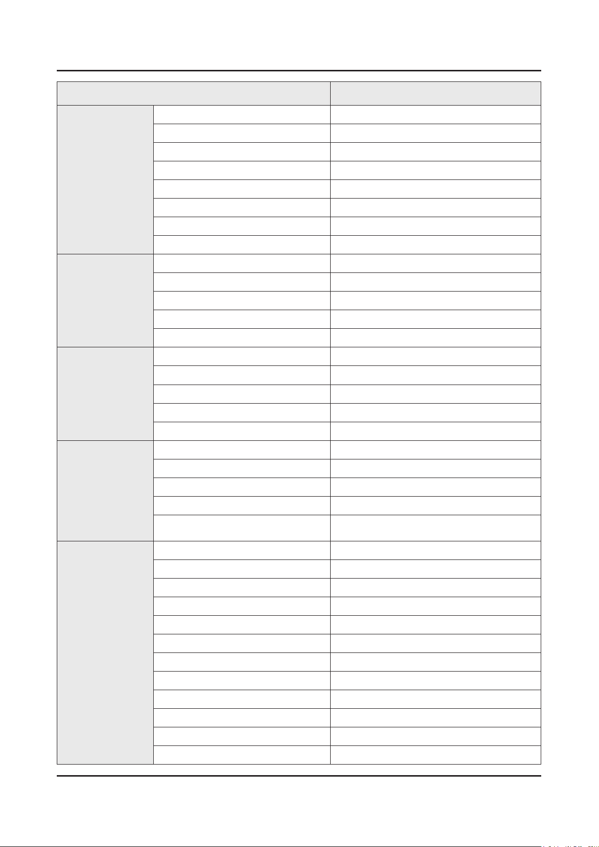
Item UE**H5500AWXXH
Smart TV
Smart Interaction
Smart Convergence
Multimedia Yes
Apps Yes
Game Yes (7 European Countries)
Fitness Yes
Kids No
Multi-Screen (Dual / Quad Screen) N/A
Skype™ on Samsung TV Yes
Web Browser Yes
Voice Interaction N/A
Voice Control N/A
Camera Built-in N/A
Face recognition No
Motion control No
Contents Streaming Yes
Screen Mirroring Yes
Samsung SMART View Yes
Tuner/Broadcasting
Connectivity
Smart Home Yes (FR,DE,SE)
Easy Pin pairing Yes
Twin Tuner N/A
CI/CI+/2CI+ CI+ (1.3)
DTV Tuner DVB-T/C
Analog Tuner Yes
MHP / MHEG / HbbTV / ACAP / GINGA /
OHTV
HDMI 3
USB 2
Component In (Y/Pb/Pr) 1
Composite In (AV) 1 (Common Use for Component Y)
Ethernet (LAN) Yes
Headphone Yes
Digital Audio Out (Optical) 1
RF In (Terrestrial / Cable input) 1/1(Common Use for Terrestrial)/0
Ex-Link ( RS-232C ) No
HbbTV ( ES, PT, FR, BE, NL,, LU, CH. PL, CZ )
IR Out Yes
CI Slot 1
Scart 1
Page 12
2-4
2. Product specications
Item UE**H5500AWXXH
Connectivity
Design
Additional Feature
MHL CE 3.0 N/A
One Connect (Jack) N/A
WiFi Direct Yes
HDMI 1.4 3D Auto Setting N/A
HDMI 1.4 A/Return Ch. Support Yes
InstaPort S (HDMI quick switch) N/A
Wireless LAN Adapter Support N/A
Wireless LAN Built-in Yes
Anynet+ (HDMI-CEC) Yes
Design RHCM
Bezel Type VNB
Front Color Black
Light Effect (Deco) N/A
Stand Type Square Mold
Swivel (Left/Right) N/A
Samsung 3D N/A
3D Converter N/A
Instant On N/A
Quad Core+ No
Accessibility ZOOM
Auto Power Off Yes
Clock&On/Off Timer Yes
Sleep Timer Yes
BD Wise Plus N/A
Caption (Subtitle) Yes
Channel List USB-Clone Yes
ConnectShare™ (USB 2.0) Movie
Football Mode Advanced
Embeded POP Yes
EPG Yes
PVR Ready Yes
Game Mode Yes
Multiroom Compatible No
OSD Language 27 European Languages
Picture-In-Picture Yes
Page 13
2-5
2. Product specications
Item UE**H5500AWXXH
Additional Feature
Eco Feature
Accessory
BT HID Built-in N/A
USB HID Support Yes
Smart Evolution Support N/A
TV SoundConnect N/A
Teletext (TTXT) Yes
Time Shift Yes
Eco Sensor Yes
Energy Efciency Class 48" : A++ A+
Mercury Content 0.0mg
Lead Presence Yes
3D Active Glasses (Included) N/A
Remote Controller Model TM1250A
Batteries (for Remote Control) Yes
Samsung Smart Touch Control (Included) N/A
Ultra Slim Wall Mount Supported N/A
Mini Wall Mount Supported Yes
Vesa Wall Mount Supported Yes
Floor Stand Support N/A
TV Camera (Included) N/A
IR Extender Cable (Included) Yes
Wireless Keyboard (Included) N/A
Wireless LAN Adaptor (Included) N/A
User Manual Yes
E-Manual Yes
Power Cable Yes
Slim Gender Cable N/A
Page 14
2-6
2. Product specications
2-2-2. Specications
Specications
Model UE**H5500AW
Item Description
Screen Size (Diagonal) 32 inches 40 inches 48 inches 50 inches
LCD Panel FHD 60Hz
Display Colors 16.7M color
Display Resolution 1,920 x 1,080
Input Signal Analog 0.7 Vp-p ± 5% positive at 75Ω, internally terminated
Input Sync Signal H/V Separate, TTL, P. or N.
Maximum Pixel Clock Rate 74.25MHz
AC Power Voltage & Frequency [EU : AC 220~240V, CIS : AC 110~240V], 50/60 Hz
Environmental Considerations Operating Temperature: 32˚F ~ 122˚F (0˚C ~ 50˚C)
Operating Humidity: 20% ~ 90%
Storage Temperature: -4˚F ~ 140˚F (-20˚C ~ 60˚C)
Storage Humidity: 10% ~ 90%
Sound (Output) 20W (10W X 2)
Page 15
2-7
2. Product specications
2-3. Accessories
NOTE
The items’ colors and shapes may vary depending on the model.•
Cables not included in the package contents can be purchased separately.•
The part code for some accessories may differ depending on your region.•
Product Code. No Product Code. No
Remote Control• BN59-01178B User Manual• BN68-06010C
Batteries (AAA x 2)• 4301-000121
Power Cord• 3903-000849
Image Product Code. No
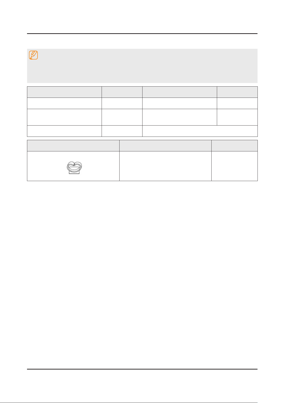
Holder-Wire Stand• BN61-08370A
Warranty Card (Not available •
in some locations)
BN68-03548J
Page 16
3. Disassembly and Reassemble
3. Disassembly and Reassembly
This section of the service manual describes the disassembly and reassembly procedures for the LED TV.
This LED TV contains electrostatically sensitive devices. Use caution when handling these components.
WARNING
3-1. Disassembly and Reassembly
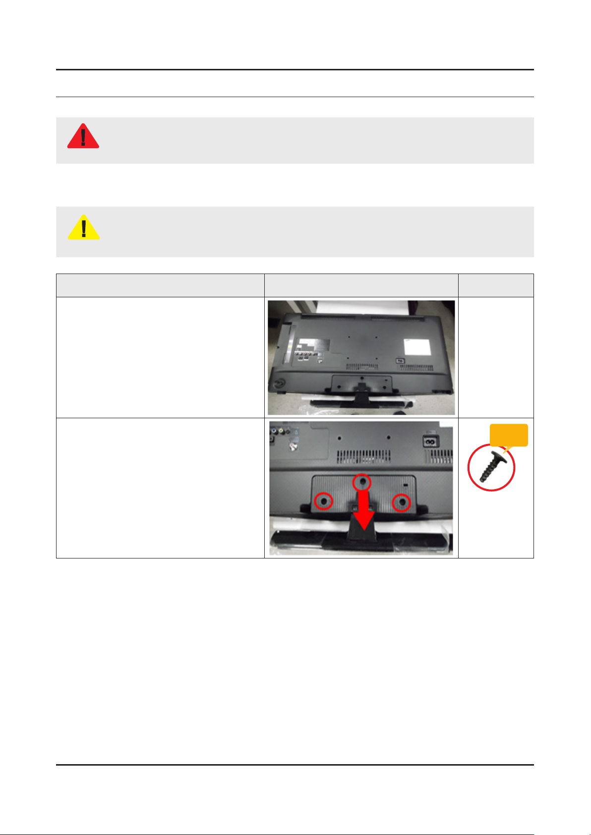
Disconnect the LED TV from the power source before disassembly.1.
Follow these directions carefully; never use metal instruments to pry apart the cabinet.2.
CAUTION
Place TV face down on cushioned table.
If there is no additional coment, it is same for all inches.3.
Description Picture Description Screws
1
Remove screws from the Stand and
2
Remove Stand.
32" : 3ea -
40"/48"/50" : 4ea -
Torque :
9~ 10Kgf.cm
6003-001782
3-1
Page 17
3-2
3. Disassembly and Reassemble
Description Picture Description Screws
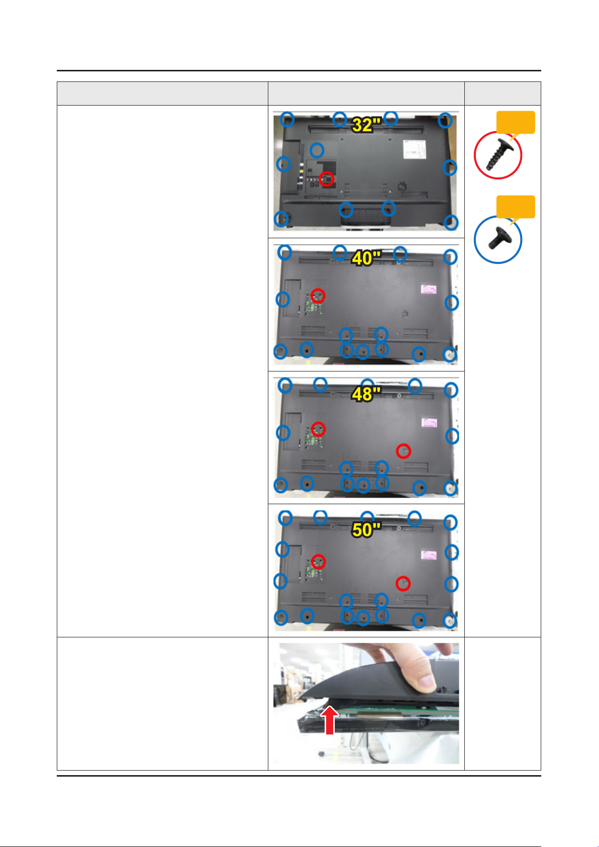
Remove screws of Rear Cover.
3
32" : 12ea -
40" : 16ea -
48" : 18ea -
Torque :
9~ 10Kgf.cm
6003-001782
Torque :
7~ 8Kgf.cm
6003-002755
50" : 20ea -
Remove the Rear-Cover.
4
Page 18
3-3
3. Disassembly and Reassemble
Description Picture Description Screws
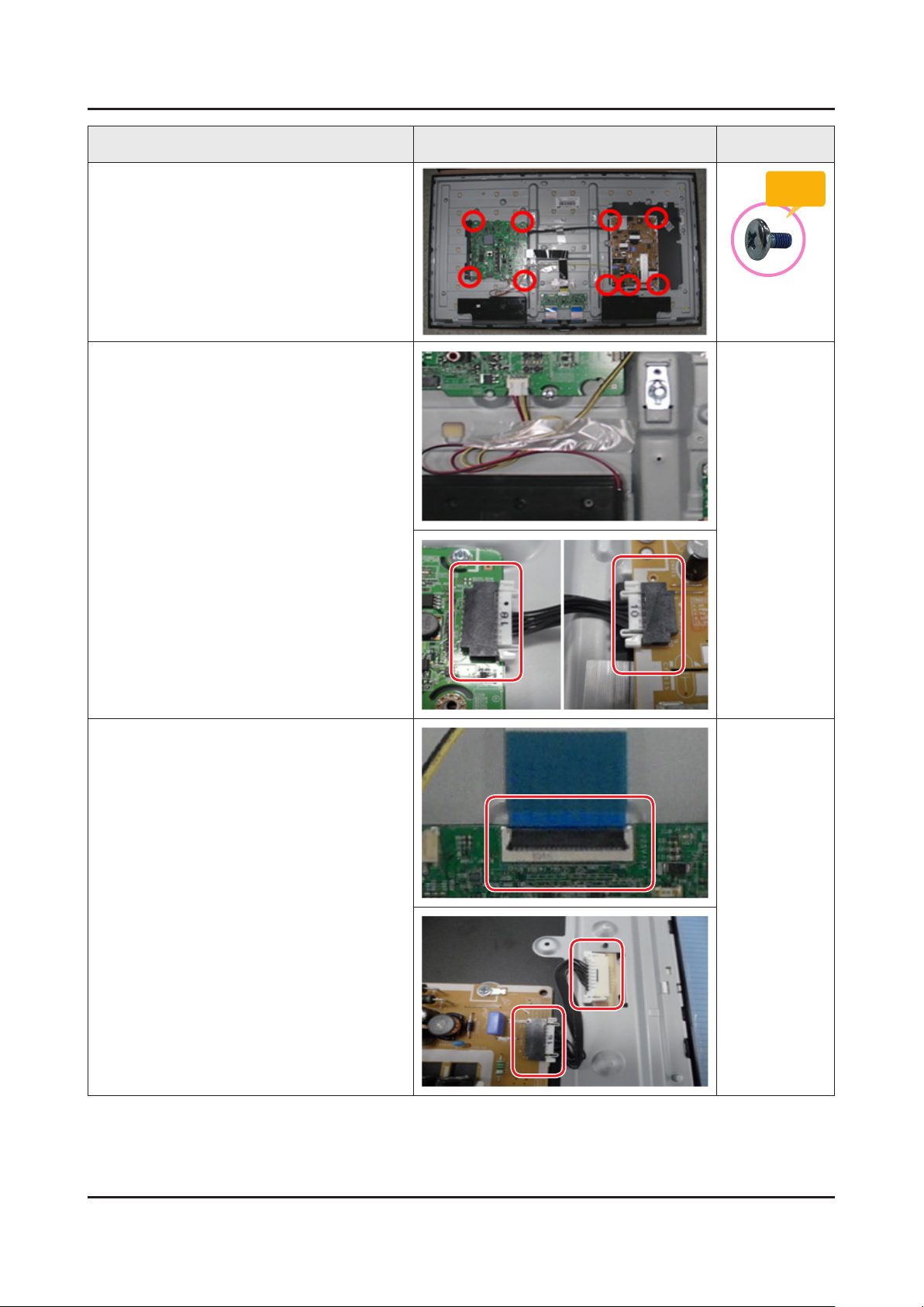
Remove 9 screws of Main Board and
5
Power Board.
Remove the Speakers and Power Cables.
6
Torque :
7~ 8Kgf.cm
6001-003016
Remove the LVDS Cable and Panel Drive
7
Cable.
Page 19
3. Disassembly and Reassemble
Description Picture Description Screws
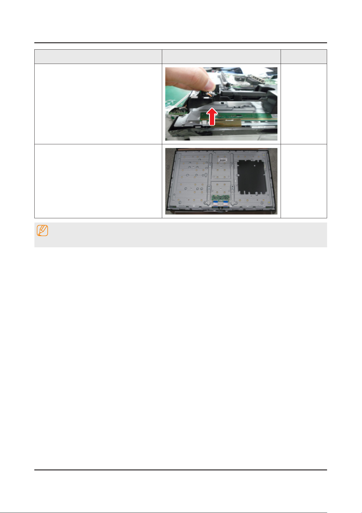
Remove the function
8
Completed disassembly.
9
NOTE
Reassembly procedures are in the reverse order of disassembly procedures.
3-4
Page 20
4. Troubleshooting
4-1. Troubleshooting
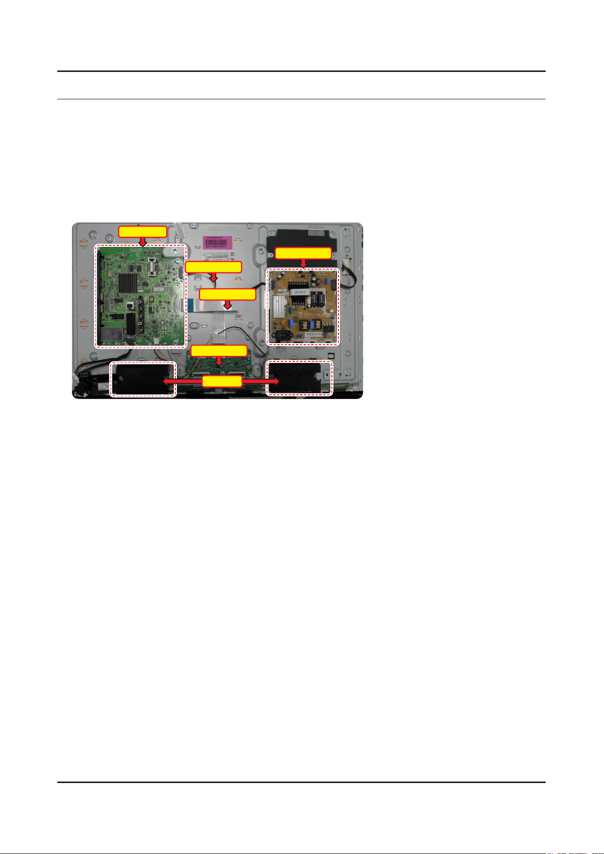
4-1-1. Previous Check
Check the various cable connections rst.1.
Check to see if there is a burnt or damaged cable. -
Check to see if there is a disconnected or loose cable connection. -
Check to see if the cables are connected according to the connection diagram. -
Check the power input to the Main Board.2.
Main Board
Power Cable
T-con Board
4. Troubleshooting
Power Board
LVDS Cable
Speaker
How to distinguish if the problem is caused by 3. Main Board or T CON
4-1
Page 21
4-2
4. Troubleshooting
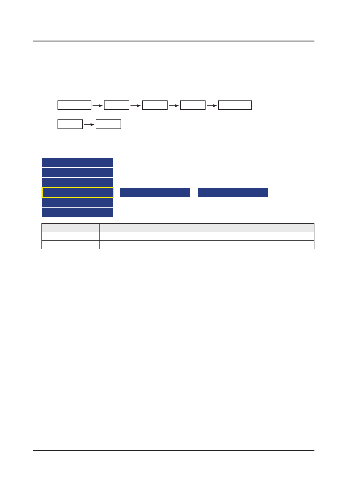
How to know it is from Main Board or T-Con when some problems happen
No Picture : Backlight is on, but there is no picture and LED indicator in front of TV is blinking.1.
Check the LVDS Cable connection. If still problems, change the T-Con Board and then Main Board step by step. -
Picture distortion : Enter the service mode 2. ⇢ Choose ‘SVC’ ⇢ Check the ‘internal pattern.’
Enter ‘Service Mode.’ -
If you do not have Factory remote control•
Power OFF Info MENU Mute Power On
If you have Factory remote control•
INFO Factory
Choose ‘SVC.’3.
Choose ‘Test pattern.’4.
Select the each pattern and then check all pattern is ok or not.5.
Option
Control
Debug
SVC
ADC/WB
Advanced
Pattern Status is Change the Test Pattern is made by the NOVATEK IC
OK Main Board We guess front of NOVATEK IC has problem.
NG Panel and T-Con Board We guess back of NOVATEK IC has problem.
Test Pattern Pattern Sel
Page 22
4-2. How to Check Fault Symptom
4-3
4. Troubleshooting
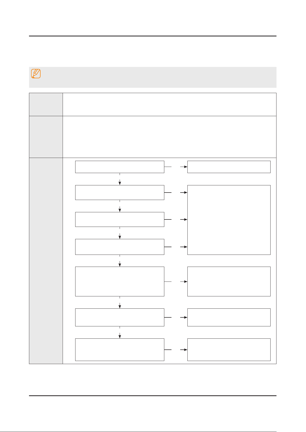
4-2-1. NO Power
Note
Refer to the next page to check the location such a CN201 or IC201 SVC Manual mentioned.
The LEDs on The front panel do not work when connecting The power cord.•
Symptom
Major
checkpoints
The SMPS relay does not work when connecting The power cord.•
The units appears to be dead.•
The IP relay or the LEDs on the front panel does not work when connecting the power cord if the cables are
improperly connected or the Main Board or SMPS is not functioning. In this case, check the following:
Check the internal cable connection status inside the unit.•
Check the fuses of each part.•
Check the output voltage of SMPS.•
Replace the Main Board.•
Diagnostics
Power indicator LED is on?
Yes
Check the backlight on, when 18 PIN
cable unconnected ?
Yes
Check ‘Stand-By 5V’ ?
L204 : A5.3V
Yes
Check ‘Power input of Main Ass’y’ ?
BD201/206/209/214 : A13V -
Yes
Check ‘Power IC output of Main Ass’y’ ?
IC202 : A3.3V -
L305/306 : B1.1V / L201 : B5V -
L203 : B3.3V / L2001 : A1.5V -
Yes
Check Input power of ‘T CON Board’ ?
F1(T CON) : B13V -
No
No
No
No
No
No
Check the power cord connection.
Change 18p cable.
Change Main Power Ass’y.
Change the Main Ass’y.
Reconnect or Change.
the LVDS cable.
Yes
Check Power of ‘T CON Board’.
BD1(T CON) : Panel_12V -
B1.1V(T CON-TP) : FT1_1.1V_PW -
No
Change the T CON Board.
Page 23
4-4
4. Troubleshooting
Yes
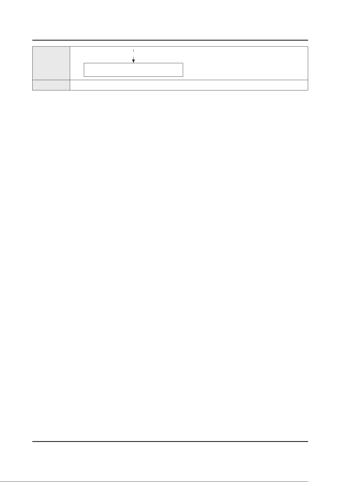
Diagnostics
Please, Contact tech support.
Caution Make sure to disconnect the power before working on the IP Board.
Page 24
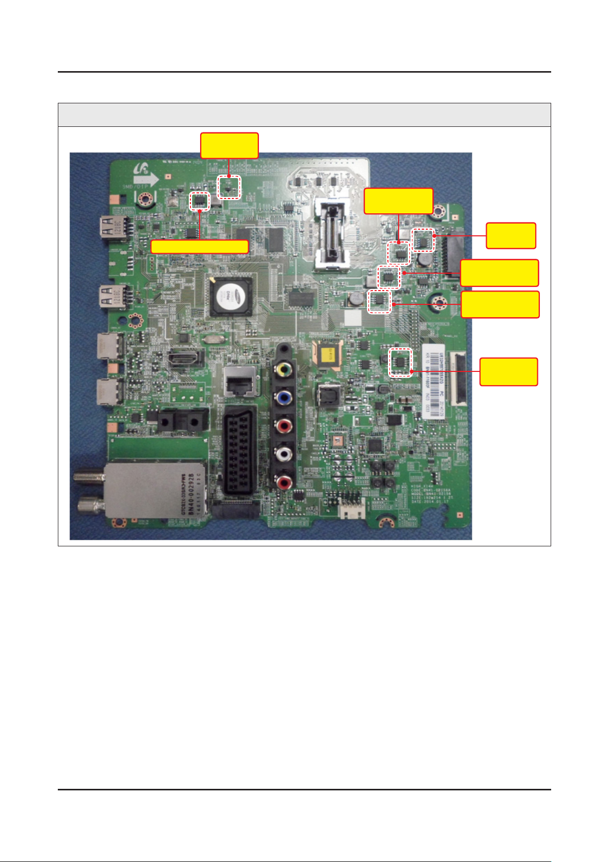
4-5
4. Troubleshooting
Location of Parts
Main Board_Front
A3.3V_PW
(IC202)
B5V_DC_PW
(IC201)
BAV_PW
A1.5V_DDR_PW (IC)
B1.1V_CORE_PW
(IC206)
(IC304)
B1.1V_CPU_PW
(IC305)
B3.3V_PW
(IC 208)
Page 25
4-6
4. Troubleshooting
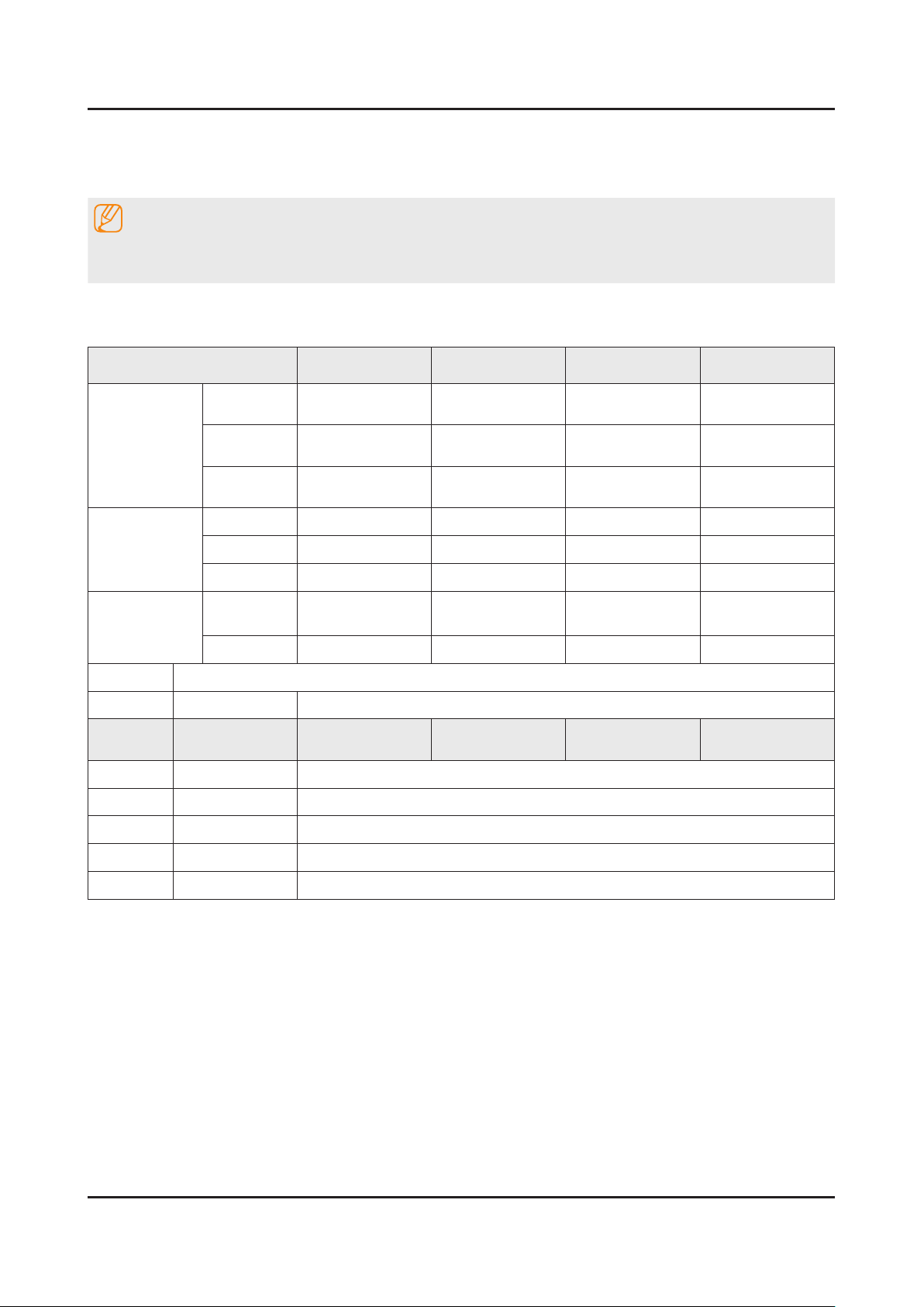
4-3. Factory Mode Adjustments
4-3-1. Detail Factory Option
NOTE
If you replace the main board with new one, please change the factory option as well.
The options you must change are "Type".
UE**H5500AWXXH
Inches 32" 40" 48" 50"
AUO
SDC
BN07-01358B
BN95-01325B
GH032BGLV2H
GH032BGLV2H/V
SEM SEM SEM HANSOE
BN44-00697A BN44-00703A BN44-00703A BN44-00704A
L32SF_ESM L48S1_ESM L48S1_ESM L55S1_EHS
BN91-11600A BN91-11600G BN91-11600N BN91-11600U
BN94-07369A BN94-07369G BN94-07369N BN94-07369U
BN95-01316B BN95-01317B
GH040BGLV2V GH048BGLV2V
PANEL
SMPS BOARD
MAIN BOARD
Vendor
Code
Spec.
Vendor
Code
Spec.
Chassis
Ass'y
PBA Ass'y
Byte Item
0 Factory Reset
1 Type
32R6AF0V
32A6AF0V
40A6AF0V 48A6AF0V
2 Local set
3 SW Model
4 BOM Model
SDC SDC
-
EU
H5500
5500
AUO
INX
BN07-01359B
BN95-01320B
GH050BGA-B2
GH050BGNV2V
50R6AF0V
50D6AF0V
5 Tuner
6 Ch table
DVB-T/C
NONE
Page 26
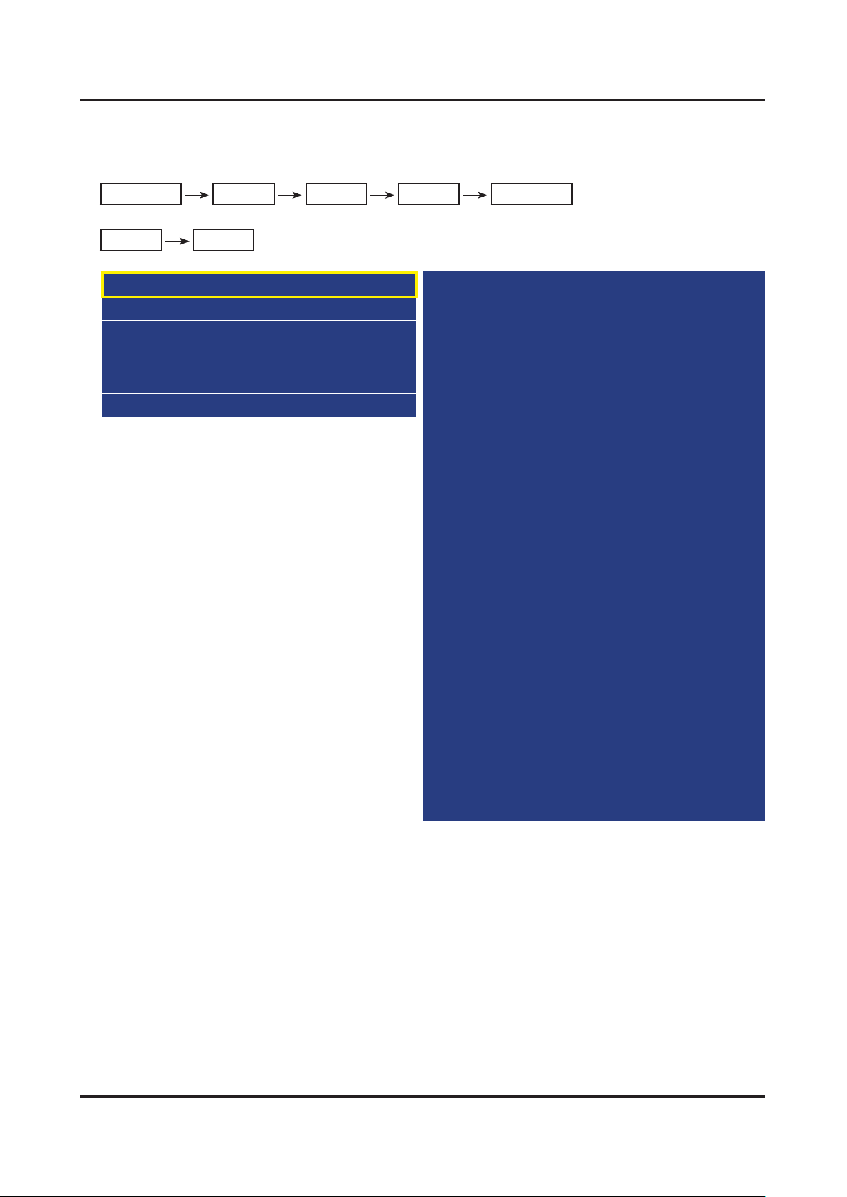
4-3-2. Entering Factory Mode
4-7
4. Troubleshooting
To enter ‘Service Mode’ Press the remote -control keys in this sequence :
If you do not have Factory remote control•
Power OFF INFO MENU MUTE Power On
If you have Factory remote control•
INFO Factory
If you don’t have Factory remote control, can’t control some menus. •
Option
Control
Debug
SVC
ADC/WB
Advanced
T-MST14DEUC-xxxx
T-MST14EDUS-xxxx
BT Version : xxxx
E-Manual : xxxx
Camera Version : xxxx
Blaster Version : xxxx
EDID SUCCESS
CALIB : AV/COMP/PC/HDMI/
Option : xxxx,xxxx,55xx,NONE
SDAL-X14H-MAIN-xxxx-xxxx
RFS : "X14 00xx" KER/1 201x-xx-xx
KERNEL : 9.0915, D /
DTP-DTVTD-xxxx-xx
Backend[x] Panel[x]
FW[xxxx] Data[xxxx]
TCON Version : xxxx
Model : UExxH55xx
Wired MAC SUCCESS
Wireless MAC SUCCESS
WIFI : ATH6KL(5.0.0.69.0518)
CIP SUCCESS
DRM : Crt O, Nf/ , Wv/ , Hc O, Dc/ , Mx/ , MI/
Factory Data Ver : xxx
EERC Version : xx
DTP-BP-HAL-xxxx
DTP-BP-MW-xxxx
DTP-BP-APP-xxxx
Date of purchase : mm/dd/yyyy
Page 27
4-8
4. Troubleshooting
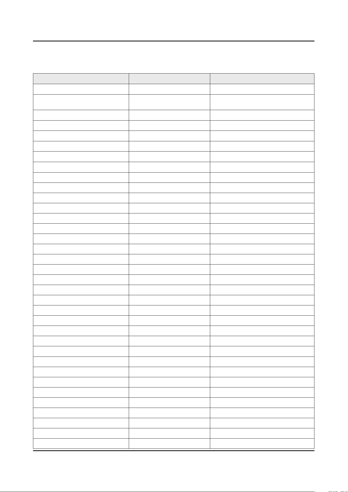
4-3-3. Factory Data
Option
Factory Menu Name Data Range
Factory Reset
Type
Local Set
SW Model
BOM Model
TUNER
Ch Table
-
32R6AF0V/40A6AF0V/48A6AF0V/
50R6AF0V
EU/EU-GER/EU-UK/EU-SPAIN/CIS
UH5500
5500
S_TC
NONE
SSXZG - 5570
MRT Option
Front Color U-T-CL-M63
LVDS FORMAT JEIDA
Language_Arabic EU
Region PANEURO
PnP Language DEU
WIFI REGION E
OTN Support ON
OTA Support GENERAL
TTX ON
China HD OFF
NT Conversion OFF
Num of DTV DECODER 2
Num of AV 1
Num of COMP 1
Num of HDMI 3
Num of SCART 1
Num of USB Port 2
Num of USB 3.0 0
Num of RVU 0
Num of Display 2
Num of IPTV 0
Num of RUI 0
Num of PVR RECORD 1
TOOLS Support 1849
LNA Support OFF
24Px4 Support OFF
BD Wise Support OFF
Page 28
Factory Menu Name Data Range
4-9
4. Troubleshooting
Data Service Support OFF
JAVA Data Service Support OFF
PVR Support ON
CI Support ON
LEDMotionPlus Support ON
Natural Mode Support ON
Relax Mode Support OFF
HDMI/DVI SEL 3
Select LCD/PDP LCD
Wall Mount OFF
HV Flip HV Flip / H Filp / OFF
Light Effect OFF
e-Pop Default ON
CAMERA Support OFF
NETWORK Support Int-Wi
EcoSensor Support ON
3D Support OFF
BT Support OFF
BT ADDRESS NOT SUPPORT
HP LINE HEADPHONE
Smart Control Support OFF
Motion Recog OFF
Voice Recog OFF
Virtual Remocon Color BLACK
Local Dimming Panel OFF
Wi Vendor QCA
Engineer Option
Type Of PANEL KEY None
5 Way Function Key R BACK
Contents Bar OFF
Cable Modulation …
Standby led on/off OFF
Recognition Support ON
IF AGC 0
D AGC 0
PH BW 0
FQ BW 0
PH RATE 0
Page 29
4-10
4. Troubleshooting
Factory Menu Name Data Range
PD EN 0
PEQ Inx 33
WF Scale
WF Type 0
Number of Network Stream 1
DP V Size 0
Backend Device
BT_AUDIO_ON_OFF OFF
Cong_AV_PATH
USING_PSI_UPDATE -
ECO Standby OFF
Fast Logo Delay 0
Num of PANEL KEY 6
Panel Detail 0
Panel Init Time 500
Control
Factory Menu Name Data Range
EDID
EDID ON/OFF OFF
EDID WRITE ALL …
EDID WRITE HDMI …
EDID Ver …
EDID Port
Sub Option
RS-232 Jack UART Debug/UART
Serial Log On/Off ON
Watchdog OFF
Checksum 0x0000
Fast Boot in Production OFF
UART Enable OFF
Eeprom Reset
ECO IC TYPE MC8121
Info Link Server Type development
Info Link Country None
TTX Group UserOSD
Visual Test -
Page 30
Factory Menu Name Data Range
4-11
4. Troubleshooting
MediaPlayDB -
OPTION_SWU
OTN Server Type operating
OTN Test Server OFF
SWU Reset
SWU Duration OFF
SWU Fail Test OFF
OPTION_NUM
Num of ATV 1
Num of SVIDEO 0
Num of PC 0
Num of DVI 0
Num of OPTICAL Link 1
Num of MEDIA 1
Num of Tuner 1
Num of ISP 0
RF Remocon Support OFF
CDD mode -
DPMS Support OFF
Num of IPTV CIP 0
Num of CI 0
T-CON Device
BOARD CONTROL OFF
RM
Server Type Operating
RTS Mode OFF
PSA
FKP Download1 0
FKP Download2 0
LMK threshold 0
Low threshold 10
High threshold 15
CSB ON
CLB ON
EEPG Enable 0
Last Screen OFF
App Resume ON
BP RMS Reset 1
Page 31
4-12
4. Troubleshooting
Factory Menu Name Data Range
Fanet Thread 2
User InstantOn Default Value OFF
PDP Option
Pixel Shift Test OFF
Logic SW 0
Panel Temperature 0
LOGIC Waveform Day 0
Logic CheckSum 0
MRT 0
SAPC Timer
APC Speed
Hotel Option
Hospitality Mode OFF
Power On …
Menu OSD …
Operation …
Music Mode …
External Source …
Eco Solution …
Cloning …
Shop Option
Shop Mode OFF
Exhibition Mode OFF
3D Cube OFF
Asia Option
Unbalance OFF
AF Level adjust 3
TX Power Level 0
Mono Last Memory OFF
H Shaking OFF
SOUND
Carrier_Mute OFF
High Devi OFF
Speaker Delay Normal 0x0Ah
SPDIF PCM Gain -9dB
FM M Prescale 0x30h
FM Prescale 0x00h
AM Prescale 0x32h
Page 32
Factory Menu Name Data Range
4-13
4. Troubleshooting
NICAM Prescale 0x48h
BTSC Mono Prescale 0x19h
BTSC stereo Prescale 0x2Fh
BTSC SAP Prescale 0x2Bh
A2Ident High THID 36
A2Ident Low THID 9
Pilot Level High Thld 0x20h
Pilot Level Low Thld 0x0Fh
Carrier2 Amp High THID 4
Carrier2 Amp Low THID 3
Carrier2 SNR High THR 16
Carrier2 SNR Low THR 80
Sig Error On 35
Sig Error Off 41
Amp Model NTP7414
Amp Volume 0xc5h
Amp Scale 0x9ah
Amp Check Sum 0x1C199E11
Woofer Type 0
Woofer Volume 0xcbh
Woofer Scale 0x8ah
Woofer Check Sum NONE
Woofer Local EQ Checksum 0
Speaker EQ ON
PEQ Test Ready
Local Speaker EQ 0
Local EQ Checksum 0
SRS Tuning Parm 0
Subwoofer Support 0
India Sound OFF
AudioDock BT delay 50
Wall Filter Type 0
Bottom CheckSum 0
Bottom Local CheckSum 0
Lipsync Inx 2
Lipsync CheckSum OK:0x9631
Lipsync USB Test Ready
LipSync BT CheckSum OK:0x696A
Page 33
4-14
4. Troubleshooting
Debug
Factory Menu Name Data Range
Spread Spectrum
LVDS Spread ON
DDR Spread 1.0% Spectrum
Period 30K
Amplitude 1
HD SSC ON/Off ON
HD SSC Value 1
LVDS SSC ON/Off ON
LVDS SSC Value 0
DDR SSC ON/Off ON
DDR SSC Value 1
FRC LVDS SSC ON/OFF OFF
FRC LVDS SSC MRR 10
FRC LVDS SSC MFR 1
FRC LVDS SSC Period 1
FRC LVDS SSC Modulation 1
FRC DDR SSC ON/OFF ON
FRC DDR SSC MRR 15
FRC DDR SSC MFR 1
FRC DDR SSC Period 1
FRC DDR SSC Modulation 1
DDR Margin
A CTRL_OFFSET_0_3 0x0
A CTRL_OFFSET_D 0x0
B CTRL_OFFSET_0_3 0x0
B CTRL_OFFSET_D 0x0
ND ADJ Support OFF
MICOM POWER OFF OFF
RF Mute Time 6ms
CI+1.3 OFF
FRC
FRC FDISPLAY ON/OFF 0
3D FDISPLAY ON/OFF OFF
PC Mode ON/OFF OFF
Home Panel FRC OFF
DDR Test 0
Tuner Margin 10
Page 34
Factory Menu Name Data Range
4-15
4. Troubleshooting
MPEG Margin 100
H.264 Margin 100
CAM Wait Time
TS Clock deldy 0
TCON_TEMP READ 0
TEMP LAST 60
DCC VERSION 0x0
DCC CHK SEL 0
DCC CHECK LOCAL 0x0
DCC CHECK TOTAL 0x0
MulitACC Checksum 0
IIC Bus stop OFF
Tuner Status
DVB
SNR
BER
Signal Strength
Bandwidth
Frequency
LNA Status
FFT
Modulation
Code Rate
GI
Hier Modulation
Frequency offset
Timing offset
AGC
UCB
PLL Type
DEMOD Type
TPS Lock
RS Lock
SSI
SQI
Firmware Version
ISDB-T
FFT Size_1
Page 35
4-16
4. Troubleshooting
Factory Menu Name Data Range
Guard Interval_1
Freq. Offset_1
SNR_1
IF AGC_1
TMCC Lock_1
TS Packer_1
Master Lock_1
A_Modulation_1
A_Code Rate_1
A_Timer InterLeave_1
A_Segments Num_1
A_BER_1
B_Modulation_1
B_Code Rate_1
B_Timer InterLeave_1
B_Segments Num_1
B_BER_1
C_Modulation_1
C_Code Rate_1
C_Timer InterLeave_1
C_Segments Num_1
C_BER_1
SVC
Factory Menu Name Data Range
Self Diagnosis
Loop Back
AV Audio Test
DVIN Audio Test
CVBS Test
COMP Test
-
USB HUB Test
HDMI Test
SCART Audio Test
SCART CVBS Test
SCART RGB Test
PC Audio Test
Page 36
Factory Menu Name Data Range
4-17
4. Troubleshooting
PC Self Test
CPU …
DDR
FLASH
EEPROM
Sound AMP
HDMI Switch IC …
USB HUB IC
WIFI
LVDS
T-CON/FRC
PCB Test …
MOIP …
App Self Test
Device self Test
Voltage …
EcoSensor
BT
EXT Sound Inspection
Woofer Sound Inspection NONE
ATV CH Inspection
DTV CH Inspection
Satellite CH Inspection
Info
SVC Info 0
LOG(View Log)
ER Count
Panel Display Time
Upgrade
T-CON Usb Download Failure
T-CON CheckSum N/A
Logic Usb D/L …
SUBMICOM UPGRADE Ready
BT UPGRADE
BT FREEPAIRING ON
Function Upgrade Failure
FRC3D FW Upgrade
FRC3D LD UPGRADE Failure
Page 37
4-18
4. Troubleshooting
Factory Menu Name Data Range
Camera Upgrade
Mic Upgrade
CPLD USB Download
JP MICOM UPGRADE Failure
DP MICOM UPGRADE Failure
Jump Upgrade Failure
IR Blaster Upgrade
CPLD Download
LDC Prole Upgrade 0
Pic Data USB Update 0
Audio Data USB Update 0
Eco Data USB Update 0
Reset
Smart Hub Reset 0
EEPROM Rst 0
Factory Rst 0
OPTION_HDMI
DVI/HDMI SOUND Auto
HDMI HOT PLUG Disable
HOTPLUG SWITCHING Boot
HOT PLUG DURATION 1200ms
CLK TERM DURATION 1200ms
HDMI FLT CNT SIG 100ms
HDMI FLT CNT LOS 100ms
UNSTABLE BAN CNT 5000ms
HDMI ROBIN ON
HDMI Callback OFF
HDMI CTS THLD 8
HDMI CTS Cnt1 1
HDMI EQ AUTO
HDMI Write Type Combine
HDMI Switch NONE
DVI SET TIME 300ms
HDMI Sync DE
HDMI 3D DET 0
HOT PLUG OFF HOLD TIME
HDMI Stable Count 1
Page 38
Factory Menu Name Data Range
4-19
4. Troubleshooting
DVB CI
TS Clock delay TC 0
TS Clock delay S 0
CI Control Buf On ON
TS Clock delay CPU -1
Test Pattern
Pattern Sel OFF
Logic Pattern Sel 0
Logic Level Sel
FRC Pre Test Pattern 0
FRC Post Test Pattern 0
SOC TCON Test Pattern 0
SOC TCON Pattern Level 255
SOC TCON FRC Pattern 0
HDMI WB Pattern OFF
HDMI Pattern Sel 0
Parma Pre Test Pattern 0
Parma Post Test Pattern 0
FRC OSD Pre Pattern 0
FRC OSD Post Pattern 0
Other Setting
Delete S/N 0
IPERF Stopped
Expert
CAL Data Backup …
CaL Data Restore
ATV IF AGC SPEED 0
Auto Power LAST POWER
SVC Panel
ORIGINAL
ADC/WB
Factory Menu Name Data Range
ADC
AV Calibration /
Comp Calibraion /
PC Calibration /
HDMI Calibration /
-
Page 39
4-20
4. Troubleshooting
Factory Menu Name Data Range
ADC Result
1st_Y_GH 0
1st_Y_GL 0
1st_Cb_BH 0
1st_Cb_BL 0
1st_Cr_RH 0
1st_Cr_RL 0
2nd_R_L 134
2nd_G_L 134
2nd_B_L 134
2nd_R_H 49
2nd_G_H 49
2nd_B_H 49
White Balance
R-Offset 128
G-Offset 128
B-Offset 128
R-Gain 128
G-Gain 128
B-Gain 128
WB_W2_R_Offset 128
WB_W2_B_Offset 128
WB_W2_R_Gain 164
WB_W2_B_Gain 63
WB_N_R_Offset 128
WB_N_B_Offset 128
WB_N_R_Gain 151
WB_N_B_Gain 108
MGA
MGA On/Off OFF
R1_Gain …
B1_Gain …
G1_Gain …
R2_Gain …
B2_Gain …
G2_Gain …
R3_Gain …
B3_Gain …
Page 40
Factory Menu Name Data Range
4-21
4. Troubleshooting
G3_Gain …
R4_Gain …
B4_Gain …
G4_Gain …
R5_Gain …
B5_Gain …
G5_Gain …
R6_Gain …
B6_Gain …
G6_Gain …
R7_Gain …
B7_Gain …
G7_Gain …
R8_Gain …
B8_Gain …
G8_Gain …
R9_Gain …
B9_Gain …
G9_Gain …
R10_Gain …
B10_Gain …
G10_Gain …
MGA On/Off OFF
R1_Gain …
B1_Gain …
G1_Gain …
R2_Gain …
B2_Gain …
G2_Gain …
R3_Gain …
B3_Gain …
G3_Gain …
R4_Gain …
B4_Gain …
G4_Gain …
R5_Gain …
B5_Gain …
Page 41
4-22
4. Troubleshooting
Factory Menu Name Data Range
G5_Gain …
R6_Gain …
B6_Gain …
G6_Gain …
R7_Gain …
B7_Gain …
G7_Gain …
R8_Gain …
B8_Gain …
G8_Gain …
R9_Gain …
B9_Gain …
G9_Gain …
R10_Gain …
B10_Gain …
G10_Gain …
Page 42
4-4. White Balance
4-23
4. Troubleshooting
4-4-1. Calibration
Into the Factory Mode.1.
Select 2. ADC/WB menu.
Select 3. ADC menu.
ADC / WB
AV Calibration
Comp Calibration
HDMI Calibration
4-4-2. Service Adjustment
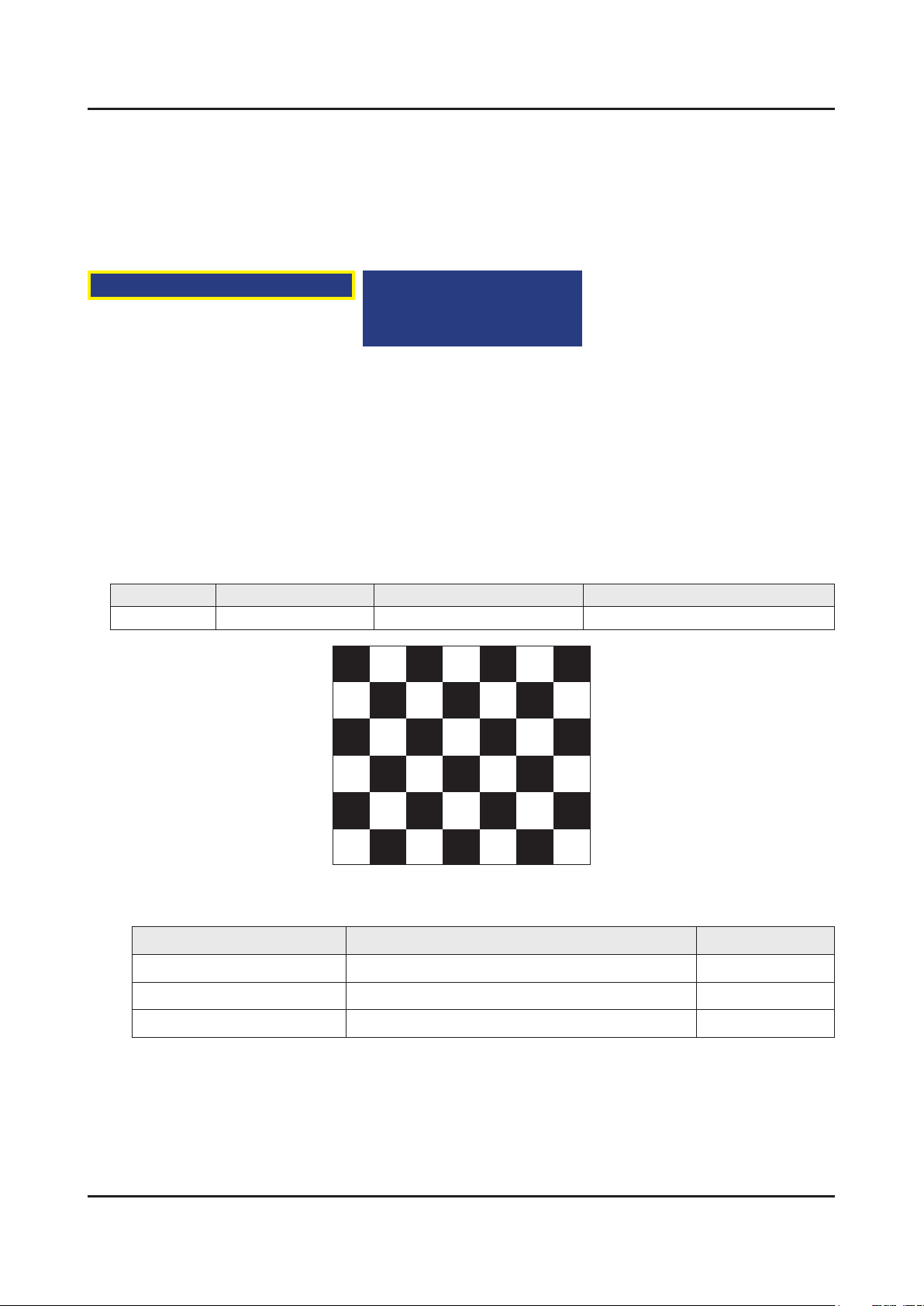
You must perform Calibration in the Lattice Pattern before adjusting the White Balance.
Color Calibration
Adjust Specication•
Source Setting Mode Pattern Use Equipment
HDMI 1280 x 720@60 Hz Pattern #24 (Chess Pattern) CA210 & Master MSPG925 Generator
(Chess Pattern)
Use other equipment only after comparing the result with that of the Master equipment. -
Input mode Calibration Pattern
CVBS IN (Model_#1) Perform in NTSC B&W Pattern #24 Lattice
Component IN (Model_#6) Perform in 720p B&W Pattern #24 Lattice
HDMI IN Perform in 720p B&W Pattern #24
Lattice
Page 43

4-24
4. Troubleshooting
Method of Color Calibration (AV)
Apply the NTSC Lattice (N0. 3) pattern signal to the AV IN 1 port.1.
Press the Source key to switch to “AV1” mode.2.
Enter Service mode.3.
Select the “ADC” menu.4.
Select the “AV Calibration” menu.5.
In “AV Calibration Off” status, press the “► ” key to perform Calibration.6.
When Calibration is complete, it returns to the high-level menu.7.
You can see the change of the “AV Calibration” status from Failure to Success. 8.
Method of Color Calibration (Component)
Apply the 720p Lattice (N0. 6) pattern signal to the Component IN 1 port.1.
Press the Source key to switch to “Component1” mode.2.
Enter Service mode.3.
Select the “ADC” menu.4.
Select the “Comp Calibration” menu.5.
In “Comp Calibration Off” status, press the “ ►” key to perform Calibration.6.
When Calibration is complete, it returns to the high-level menu.7.
You can see the change of the “Comp Calibration” status from Failure to Success.8.
Method of Color Calibration (HDMI)
Apply the 720p Lattice (N0. 6) pattern signal to the HDMI1/DVI IN port.1.
Press the Source key to switch to “HDMI1” mode.2.
Enter Service mode.3.
Select the “ADC” menu.4.
Select the “HDMI Calibration” menu.5.
In “HDMI Calibration Off” status, press the “►” key to perform Calibration.6.
When Calibration is complete, it returns to the high-level menu.7.
You can see the change of the “HDMI Calibration” status from Failure to Success.8.
Page 44

4-4-3. Adjustment
4-25
4. Troubleshooting
Into the Factory Mode.1.
Select 2. ADC/WB menu.
Select 3. White Balance menu.
ADC/WB White Balance
(Low Light)
Sub Brightness
R offset
G offset
B offset
(Hight Light)
Sub Contrast
R gain
G gain
B gain
Page 45
4-26
4. Troubleshooting
4-5. Software Upgrade
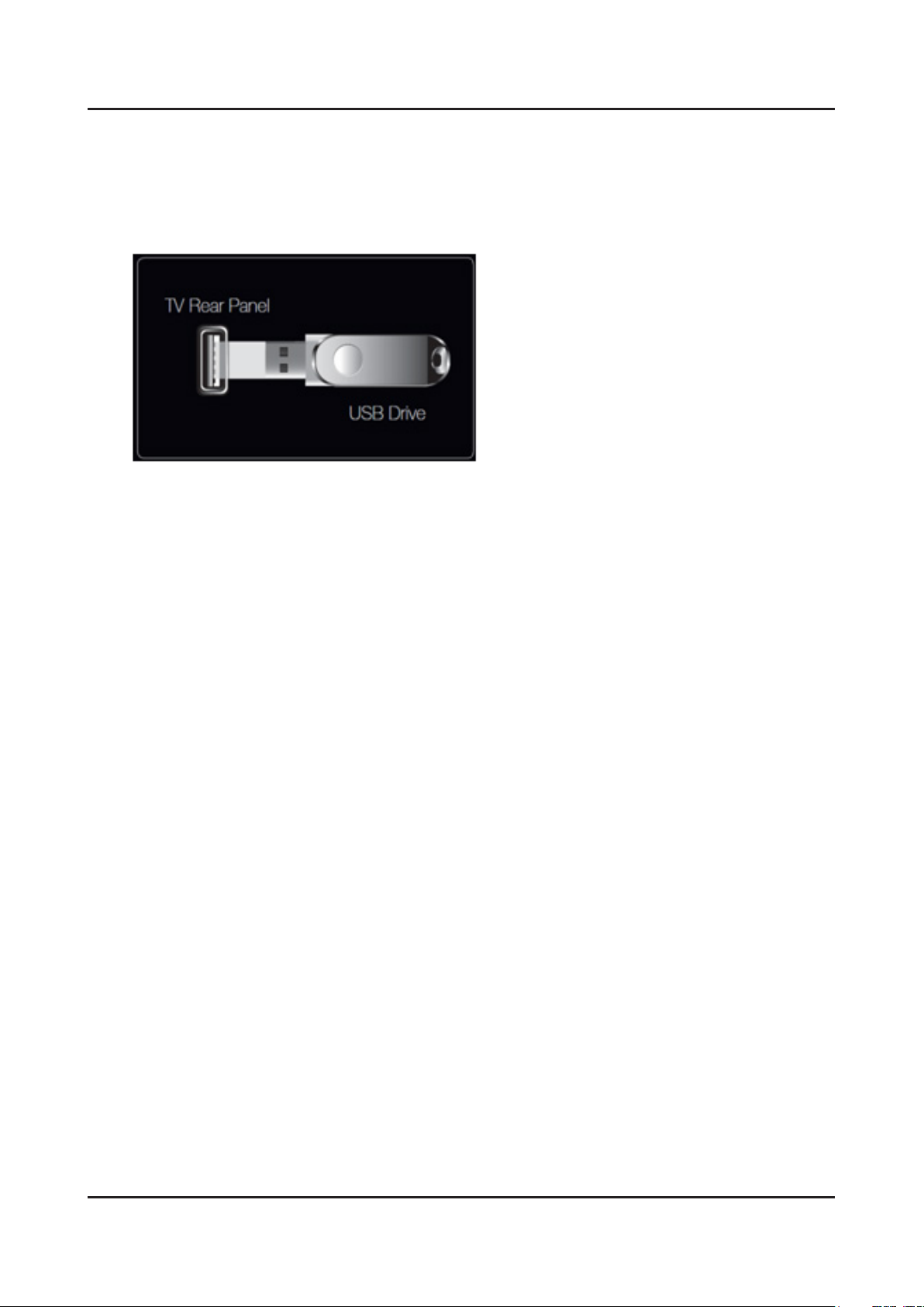
Samsung may offer upgrades for the TV’s rmware in the future. These upgrades can be performed via the TV when it is
connected to the Internet, or by downloading the new rmware from samsung.com to a USB memory device.
Alternative Software (Backup) shows The previous version that will be replaced.•
Software is represented as ‘Year/Month/Day_Version’. The more recent the date, the newer the software version •
Installing the latest version is recommended.
4-5-1. By USB
Insert a USB drive containing the rmware upgrade downloaded from samsung.com into the TV. Please be careful to
not disconnect the power or remove the USB drive while upgrades are being applied. The TV will turn off and turn on
automatically after completing the rmware upgrade. Please check the rmware version after the upgrades are complete
(the new version will have a higher number than the older version). When software is upgraded, video and audio settings
you have made will return to their default (factory) settings. We recommend you write down your settings so that you can
easily reset them after the upgrade.
4-5-2. By Online
Upgrades the software using the Internet.
First, congure your network. For detailed procedures on using the Network Setting, refer to the ‘Setting the Network’ •
instructions.
If The internet connection doesn’t operate properly, connection can be broken, please retry downloading. If the •
problem still happens, download by USB and upgrade.
4-5-3. Alternative Software (Backup)
If there is an issue with the new rmware and it is affecting operation, you can change the software to the previous
If Software was changed, existing Software is displayed.•
you can change current Software to Alternative Software by ‘Alternative Software’.•
Page 46
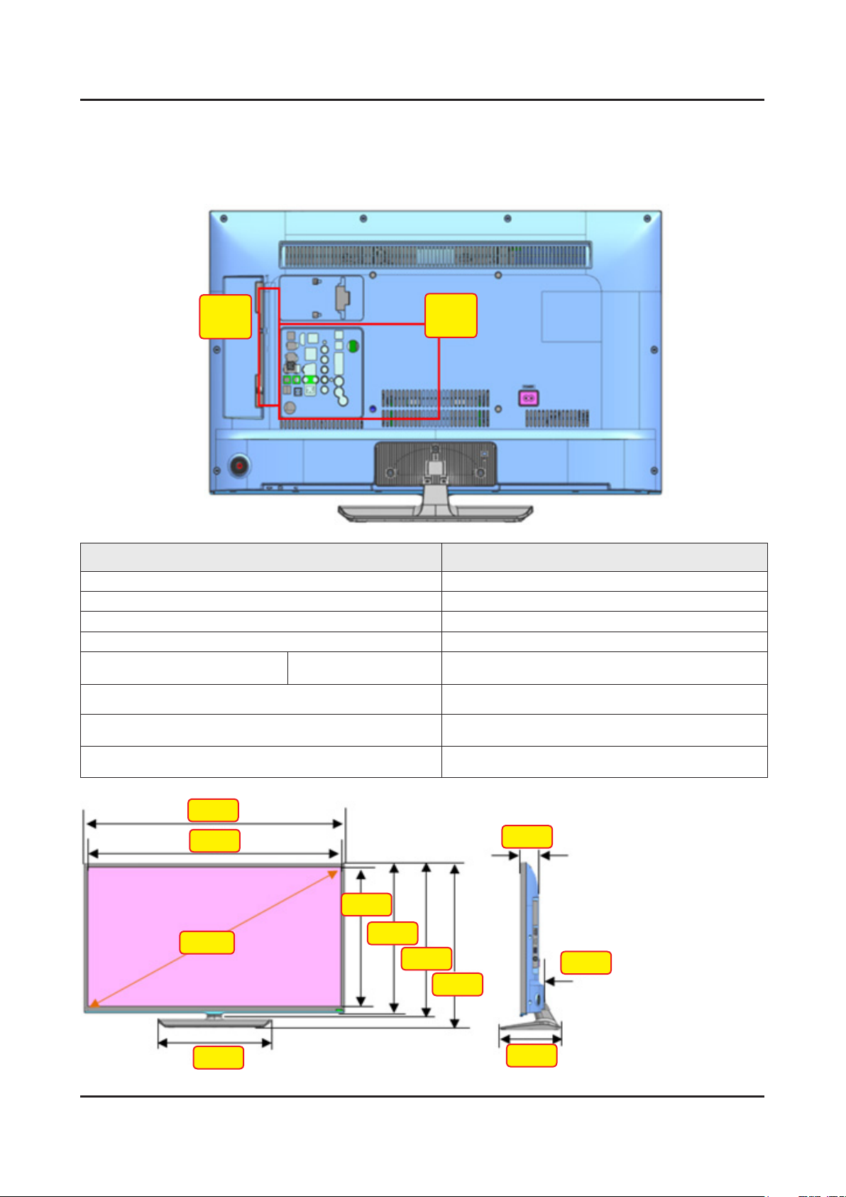
4-6. The Dimension of H55** Models
4-27
4. Troubleshooting
32 inches
B
C
Item 32"
SET Size (with Stand, W * H * D) 721.4 * 465.1 * 163.4
SET (without Stand, W * H * D) 721.4 * 428.5 * 64.9
Opening Size (W * H, Diagonal) 700.4 * 394.8 * 802.8
Wall Mount 200 * 200
Packing Size
(W * H * D)
NET (SET) Weight
(with stand)
NET (SET) Weight
(without stand)
Gross Weight
(After Packing)
W / W 899.0 * 486.0 * 108.0
5.38 kg
5.00 kg
6.55 kg
721.4
700.4
802.8
314.9
394.8
423.9
428.5
49.1
64.9
465.1
163.4
Page 47
4-28
4. Troubleshooting
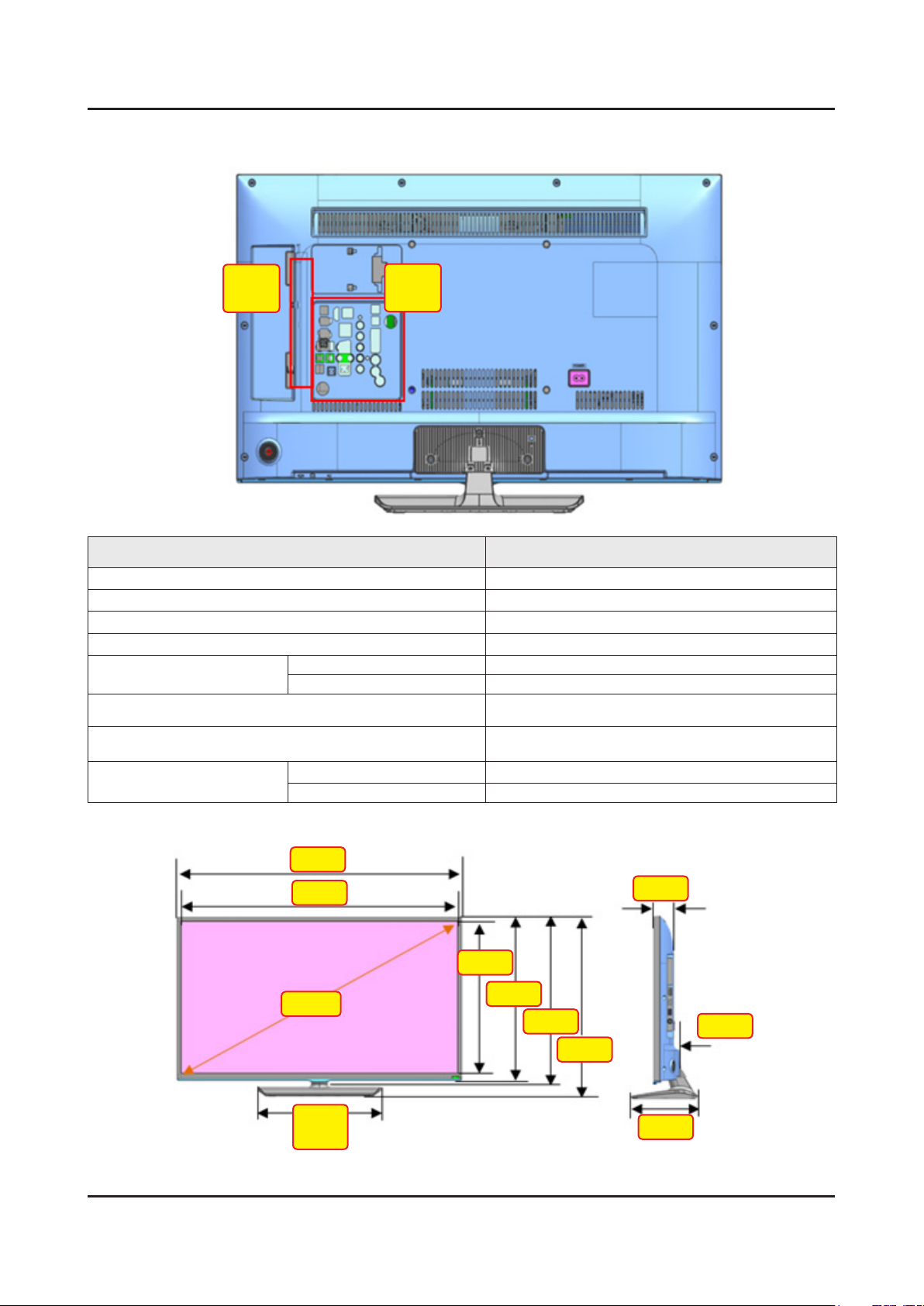
40 inches
B
C
Item 40"
SET Size (with Stand, W * H * D) 906.6 * 578.2 * 196.4
SET (without Stand, W * H * D) 906.6 * 532.9 * 65.2
Opening Size (W * H, Diagonal) 887.6 * 500.2 * 1017.7
Wall Mount 200 * 200
Packing Size
(W * H * D)
Gross Weight
(After Packing)
W / W
KR
NET (SET) Weight
(with stand)
NET (SET) Weight
(without stand)
W / W 9.8 kg (10.1 kg)
KR 9.3 kg
1100.0 * 600.0 * 120.0
1042.0 * 600.0 * 120.0
8.25 kg (8.5 kg)
7.5 kg
906.6
887.6
1017.7
385.5
(535.5)
500.2
528.3
532.9
51.3
65.0
578.2
196.4
Page 48
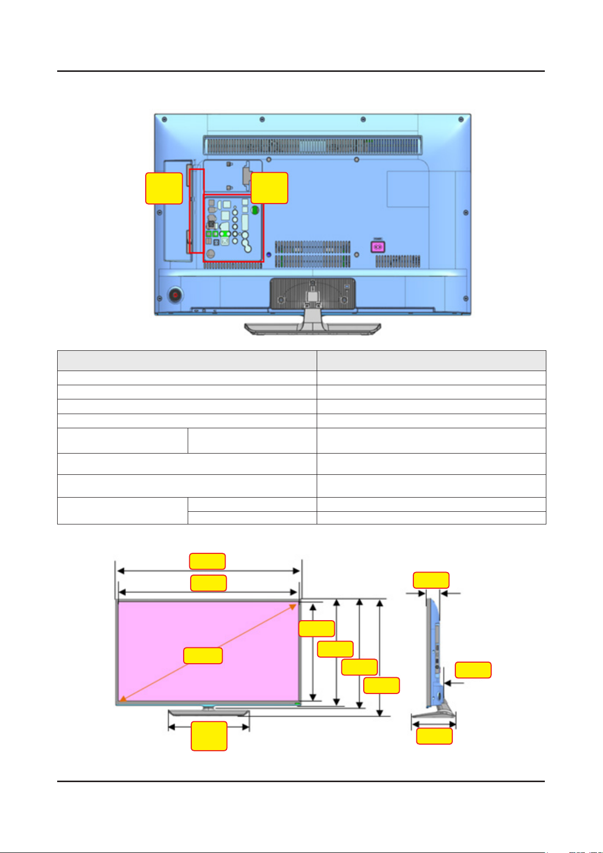
48 inches
4-29
4. Troubleshooting
B
C
Item 46"
SET Size (with Stand, W * H * D) 1075.1 * 673.8 * 203.9
SET (without Stand, W * H * D) 1075.1 * 627.6 * 65.5
Opening Size (W * H, Diagonal) 1056.1 * 594.9 * 1210.9
Wall Mount 400 * 400
Packing Size
(W * H * D)
NET (SET) Weight
(with stand)
NET (SET) Weight
(without stand)
Gross Weight
(After Packing)
W / W
W / W 15.2 kg (15.5 kg)
KR 14.1 kg
1215.0 * 706.0 * 133.0
11.9 kg (12.2 kg)
11.2 kg
1075.1
1056.1
1210.9
469.2
(598.8)
594.9
623.0
627.6
49.7
65.5
673.8
203.9
Page 49
4. Troubleshooting
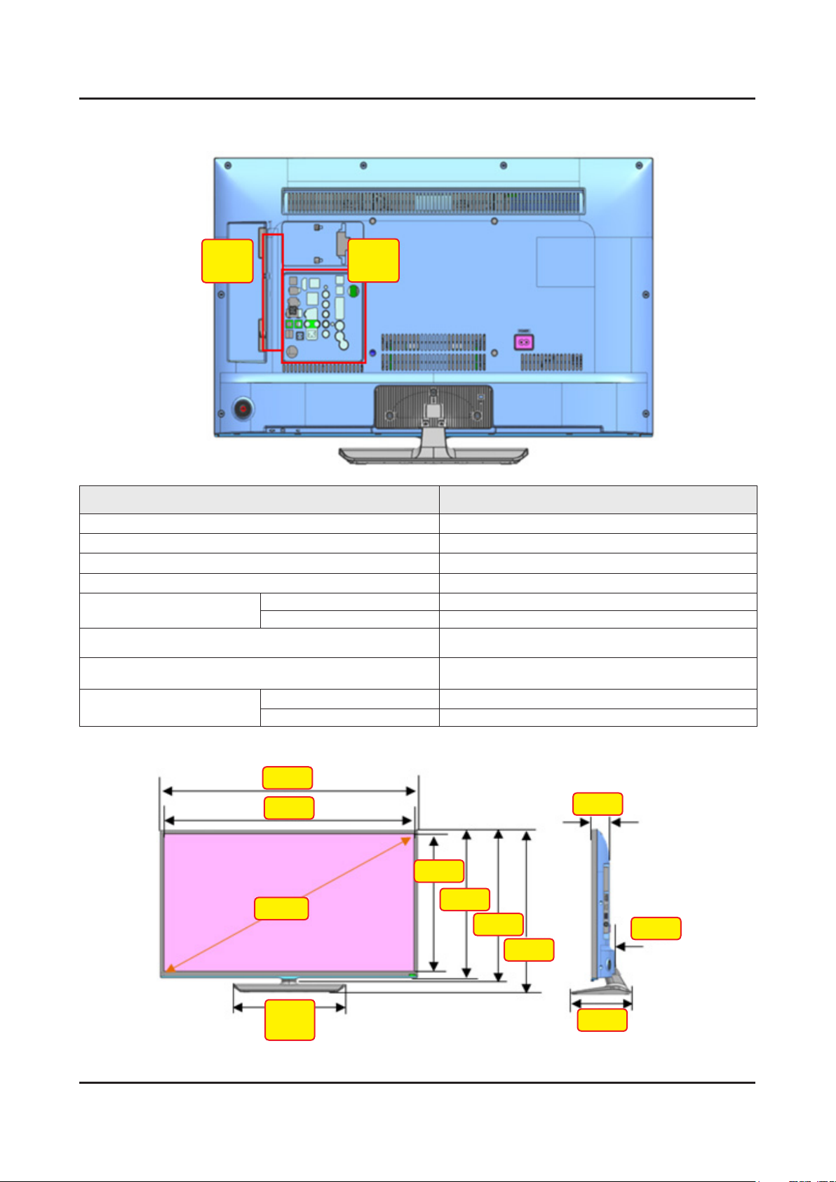
50 inches
B
C
Item 50"
SET Size (with Stand, W * H * D) 1116.8 * 696.4 * 203.9
SET (without Stand, W * H * D) 1116.8 * 651.1 * 65.7
Opening Size (W * H, Diagonal) 1097.8 * 618.4 * 1258.9
Wall Mount 400 * 400
Packing Size
(W * H * D)
Gross Weight
(After Packing)
W / W
KR
NET (SET) Weight
(with stand)
NET (SET) Weight
(without stand)
W / W 16.6 kg (16.75 kg)
KR 15.8 kg
1320 * 738 * 135
1265 * 738 * 135
13.5 kg (13.64 kg)
12.88 kg
4-30
1116.8
1097.8
1258.9
469.2
(598.8)
618.4
646.5
651.1
49.9
65.5
696.4
203.9
Page 50
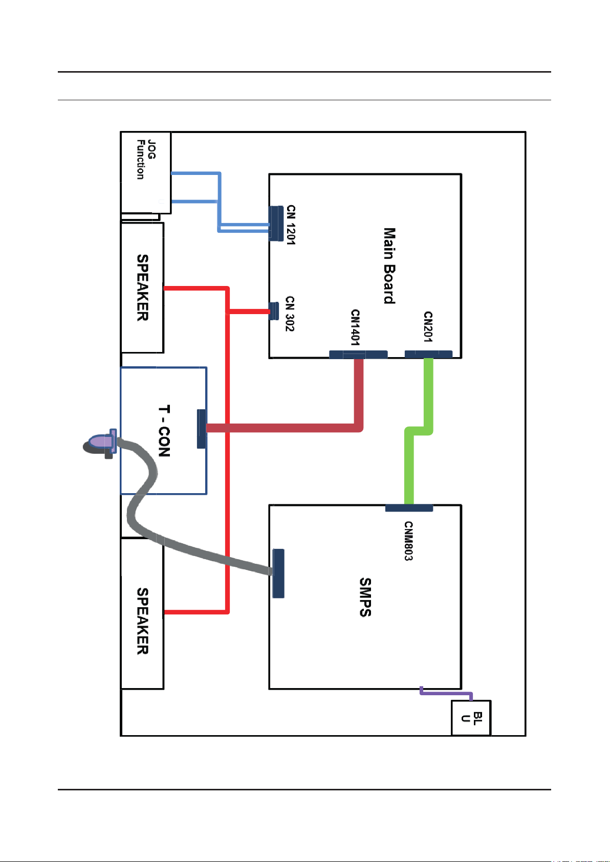
5. Wiring Diagram
5-1. Wiring Diagram
5. Wiring Diagram
5-1
Page 51
5-2
5. Wiring Diagram
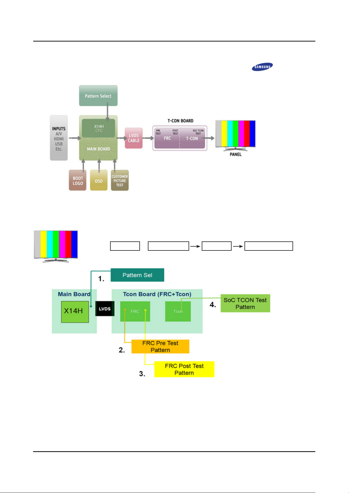
2014 LED Signal Path for Troubleshooting
CHECK TEST PATTERNS
ENTER : Factory mode SVC Info Test Pattern
1. Verify "Pattern Sel" -
2. Verify "FRC Pre Test Pattern" -
3. Verify "FRC Post Test Pattern" -
4. Verify "SoC TCON Test Pattern" -
Page 52
5-3
5. Wiring Diagram
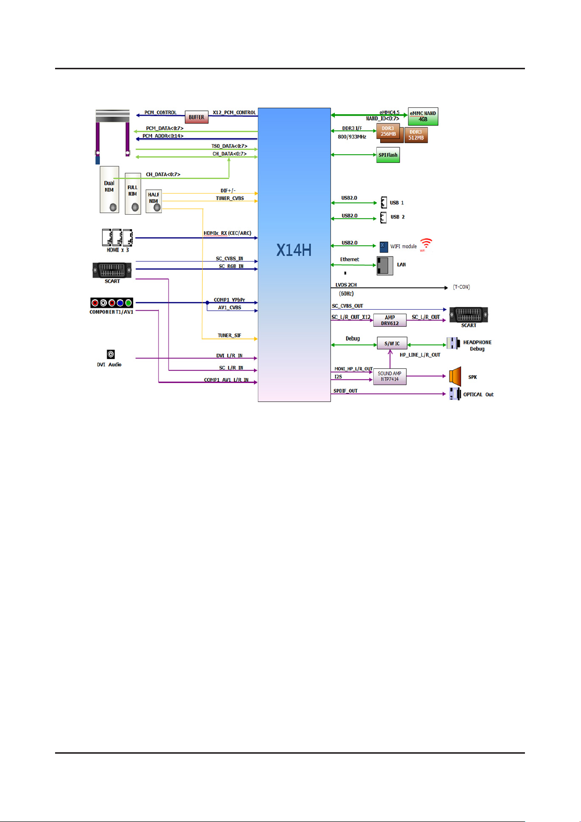
X14H(5500) Block - Diagram
Page 53
5-4
5. Wiring Diagram
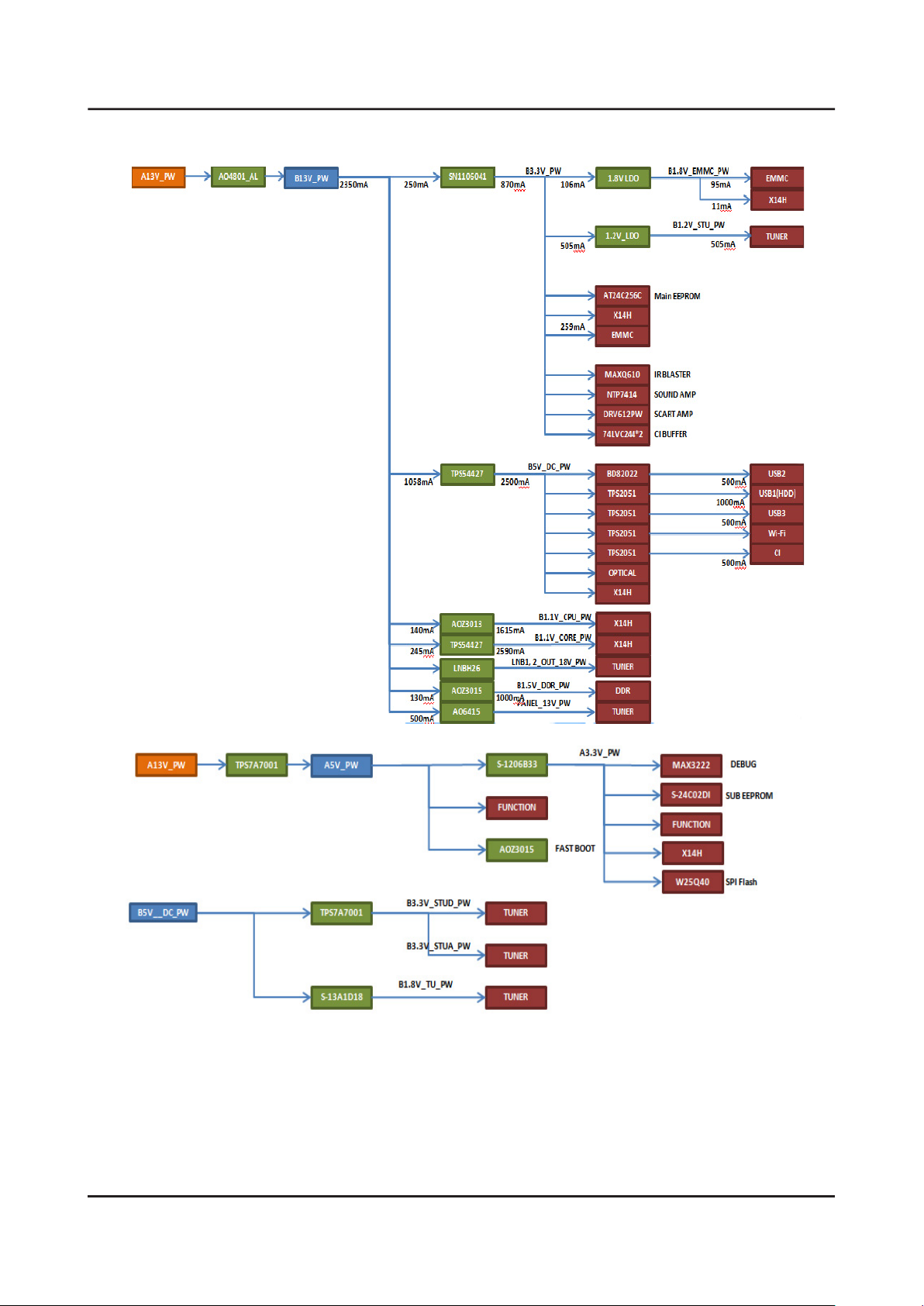
X14H Power tee
Page 54
5-5
5. Wiring Diagram
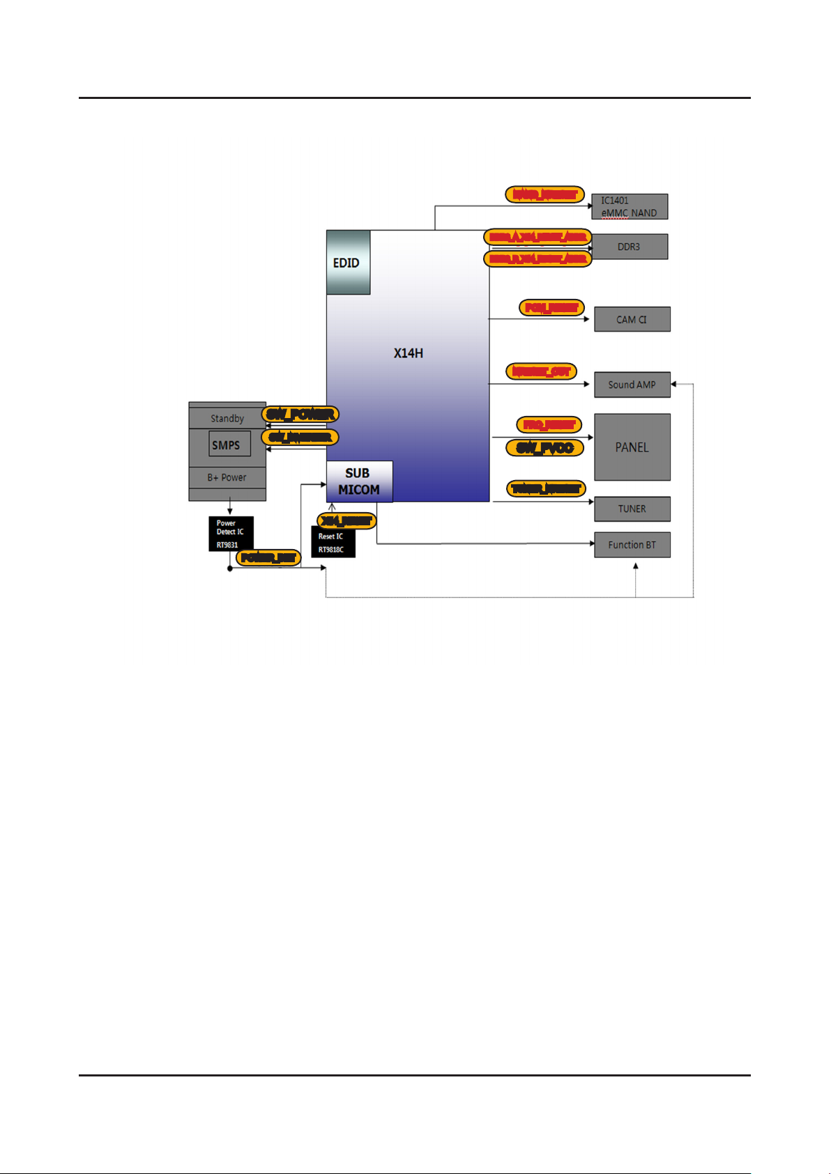
X14H RESET Tree
NAND_NRESET
DDR3_A_X14_RESET_ADDR
DDR3_B_X14_RESET_ADDR
PCM_RESET
NRESET_OUT
SW_POWER
SW_INVERTER
POWER_DET
FRC_RESET
SW_PVCC
TUNER_NRESET
X14_RESET
Page 55
5-6
5. Wiring Diagram
5-2. Connector
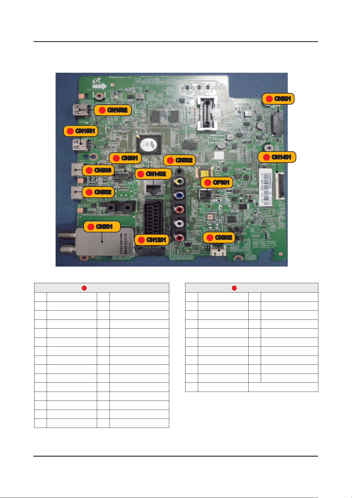
Main Board
CN1501
9
8
7
CN1502
10
CN603
CN602
6
CN601
12
CN1402
5
CN502
11
OP301
2
CN1401
1
CN201
CN501
13
CN1201
3
1
CN1401_FHD
1 NC 16 EVEN_TX3+
2 GND 17 EVEN_TX3-
3 FRC_SDA 18 GND
4 FRC_PWM1 19 EVEN_TXCLK-
5 FRC_SCL 20 EVEN_TXCLK+
6 FRC_PWM3 21 GND
7 FRC_PWM2 22 EVEN_TX2+
8 TCON_SDA 23 EVEN_TX2-
9 PANEL_I2C_EN 24 EVEN_TX1+
10 BT_SYNC 25 EVEN_TX1-
11 UPDATE_CHK 26 EVEN_TX0+
12 TCON_SCL 27 EVEN_TX0-
13 GND 28 GND
14 EVEN_TX4+ 29 ODD_TX4+
15 EVEN_TX4- 30 ODD_TX4-
CN302
4
1
CN1401_FHD
31 ODD_TX3+ 42 ODD_TX0-
32 ODD_TX3- 43 GND
33 GND 44 GND
34 ODD_TXCLK+ 45 GND
35 ODD_TXCLK- 46 FRC_PWM4
36 GND 47 PANEL_13V_PW
37 ODD_TX2+ 48 PANEL_13V_PW
38 ODD_TX2- 49 PANEL_13V_PW
39 ODD_TX1+ 50 PANEL_13V_PW
40 ODD_TX1- 51 PANEL_13V_PW
41 ODD_TX0+
Page 56
5-7
5. Wiring Diagram
2
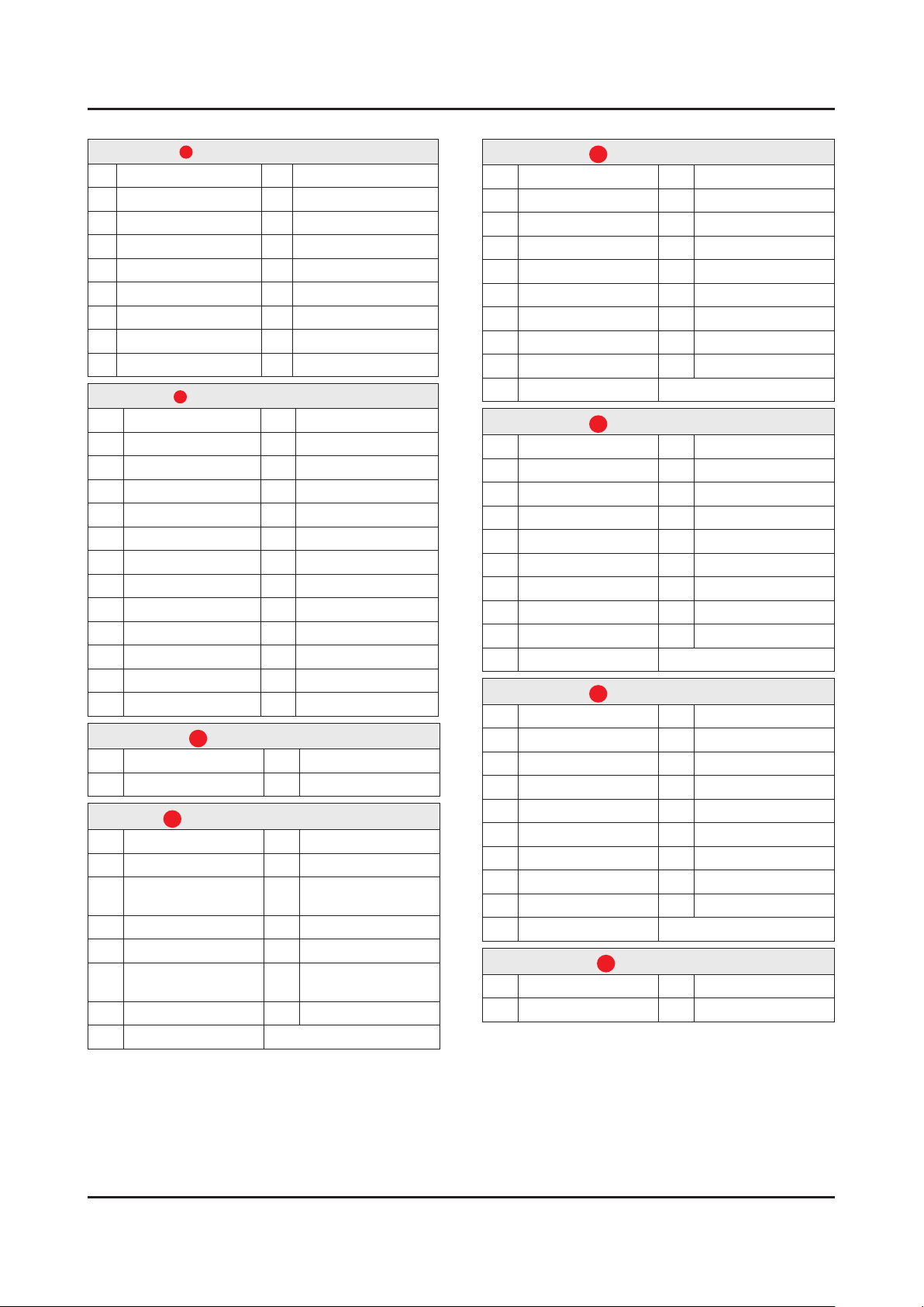
CN201 (to Powr board)
1 A13V_PW 10 SW_INVERTER
2 A13V_PW 11 A13V_PW
3 GND 12 OVD_LEVEL
4 GND 13 A13V_PW
5 A13V_PW 14 OVD_ON_OFF
6 GND 15 GND
7 A13V_PW 16 FRC_PWM1
8 SW_POWER_OUT 17 FRC_PWM2
9 A13V_PW 18 FRC_PWM3
3
CN1201 (to Function/IR)
1 IR 14 A5V
2 GND 15 LED_STB
3 GND 16 BT_WAKE
4 FRAME_SYNC_IN 17 GND
5 A3.3V 18 POWER_DET
6 BT_SYNC 19 NC
7 MSCL 20 BT_RESET
8 GND 21 GND
9 MSDA 22 WIFI_DP
10 USB_BT_DP 23 WIFI_DM
11 KEY_INPUT1 24 B5V_DC_PW
12 USB_BT_DM 25 WIFI_WOL
13 KEY_INPUT2 26 WIFI_RESET
CN302 (to Speaker)
4
1 R+ 3 L+
2 R- 4 L-
CN502 (to Component&AV)
5
1 GND 9 TEST_PR
2 COMP2_Y_CVBS 10 GND
3 INDENT_VIEDO2 11
4 GND 12 TEST_SL
5 COMP2_PB 13 GND
6 INDENT_COMP2 14
7 GND 15 TEST_SR
8 COMP2_PR
COMP2_AV2_SL_IN
COMP2_AV2_SR_IN
CN601 (to HDMI3)
6
1 HDMI1_RX2+ 11 GND
2 GND 12 HDMI1_RXCLK-
3 HDMI1_RX2- 13 CEC
4 HDMI1_RX1+ 14 NC
5 GND 15 HDMI1_SCL_DDC
6 HDMI1_RX1- 16 HDMI1_SDA_DDC
7 HDMI1_RX0+ 17 GND
8 GND 18 HDMI1_5V
9 HDMI1_RX0- 19 HDMI1_HOT_PLUG
10 HDMI1_RXCLK+
CN602 (to HDMI1)
7
1 HDMI2_RX2+ 11 GND
2 GND 12 HDMI2_RXCLK-
3 HDMI2_RX2- 13 CEC
4 HDMI2_RX1+ 14 ARC2_SIGLE
5 GND 15 HDMI2_SCL_DDC
6 HDMI2_RX1- 16 HDMI2_SDA_DDC
7 HDMI2_RX0+ 17 GND
8 GND 18 HDMI2_5V
9 HDMI2_RX0- 19 HDMI2_HOT_PLUG
10 HDMI2_RXCLK+
CN603 (to HDMI2)
8
1 HDMI3_RX2+ 11 GND
2 GND 12 HDMI3_RXCLK-
3 HDMI3_RX2- 13 CEC
4 HDMI3_RX1+ 14 NC
5 GND 15 HDMI3_SCL_DDC
6 HDMI3_RX1- 16 HDMI3_SDA_DDC
7 HDMI3_RX0+ 17 GND
8 GND 18 HDMI3_5V
9 HDMI3_RX0- 19 HDMI3_HOT_PLUG
10 HDMI3_RXCLK+
CN1501 (USB1)
9
1 B5V_USB1_PW 3 USB1_DP
2 USB1_DM 4 GND
Page 57
5-8
5. Wiring Diagram
CN1502 (USB2)
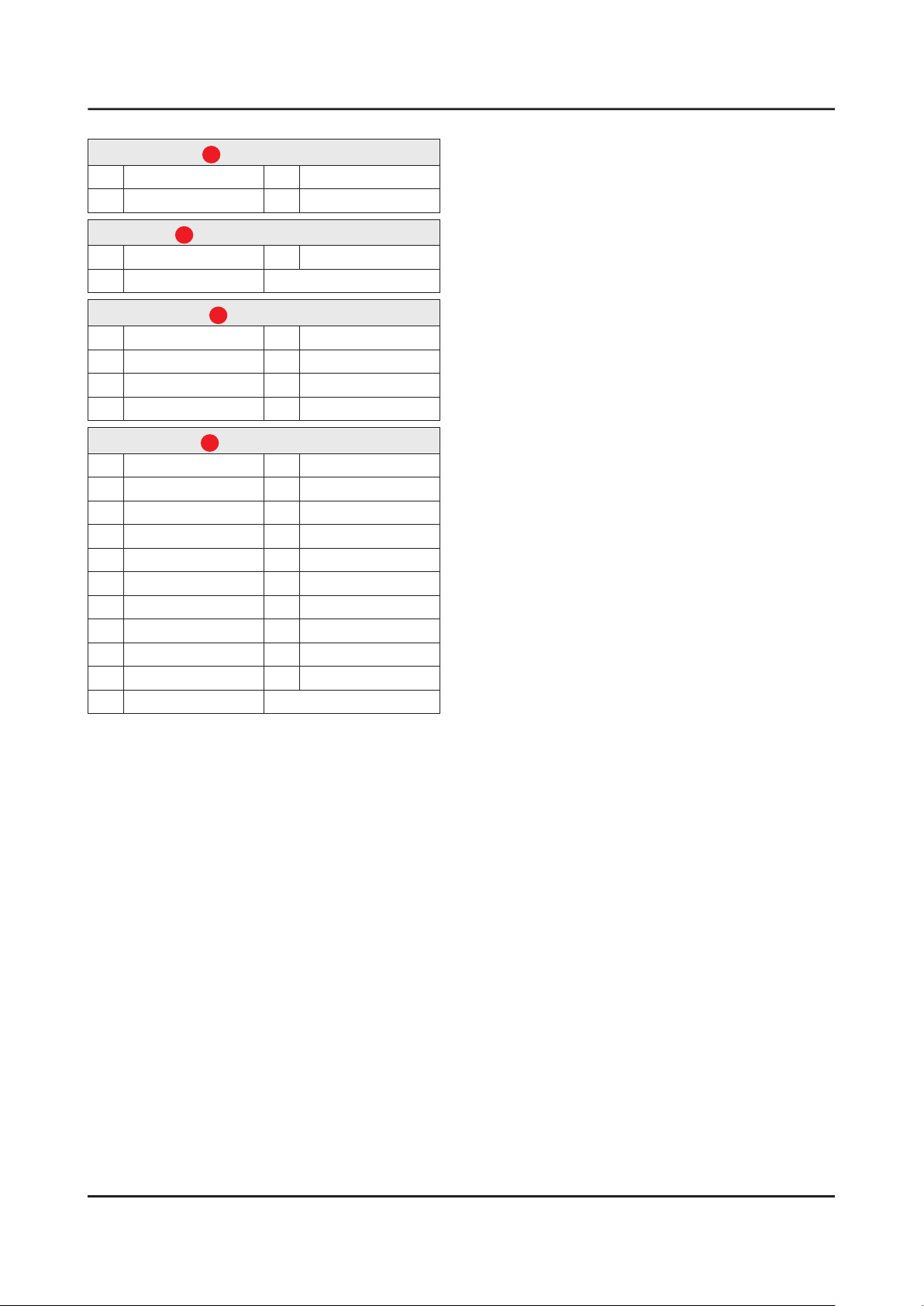
10
1 B5V_USB2_PW 3 USB2_DP
2 USB2_DM 4 GND
OP301 (to Optical Jack)
11
1 SPDIF_OUT 3 GND
2 B5V_DC_PW
CN1402_LAN
12
1 LAN_TXD+ 5 B2.5V
2 B2.5V 6 LAN_RXD-
3 LAN_TXD- 7 NC
4 LAN_RXD+ 8 GND
CN501 (SCART)
13
1 SC_SR_OUT 12 -
2 SC_SR_IN 13 GND
3 SC_SL_OUT 14 GND
4 GND 15 SC_R
5 GND 16 SC_FB
6 SC_SL_IN 17 GND
7 SC_B 18 GND
8 IDENT_SC 19 SC_CVBS_OUT
9 GND 20 SC_CVBS_IN
10 - 21 GND
11 SC_G
Page 58
5-9
5. Wiring Diagram
5-3. Connector Functions
Connector Function
CN201 CNM803
CN1401 CON3
Supply main power and dimming signal from IP Board to Main Board.
The LVDS signal transfered from Main Board to Panel.
 Loading...