

Page 1
LED-TV
Chassis : U66A
Model : UE32D55**R*
UE37D55**R*
UE40D55**R*
UE46D55**R*
UE32D57**RS
UE37D57**RS
UE40D57**RS
UE46D57**RS
Manual
Chassis : U57A
Model : UE32D50**PW
UE37D50**PW
UE40D50**PW
UE46D50**PW
UE32D40**NW
Chassis : U57B
Model : UE19D40**NW
UE22D50**NW
UE27D50**NW
SERVICE
TFT-LED TV Contents
1. Precautions
2. Product specications
3. Disassembly and Reassembly
4. Troubleshooting
5. Wiring Diagram
UE**D55****
Page 2

Contents
1. Precautions .............................................................................................................. 1-1
1-1. Safety Precautions ......................................................................................................... 1-1
1-2. Servicing Precautions ..................................................................................................... 1-2
1-3. Electrostatically Sensitive Devices (ESD) Precautions .................................................. 1-2
1-4. Installation Precautions .................................................................................................. 1-3
2. Product specications ............................................................................................ 2-1
2-1. Feature & Specications ................................................................................................. 2-1
2-2. Detail Factory Option ...................................................................................................... 2-9
2-3. Accessories .................................................................................................................. 2-11
2-4. New Features explanation ............................................................................................ 2-12
3. Disassembly and Reassembly ............................................................................... 3-1
3-1. Disassembly and Reassembly ....................................................................................... 3-1
4. Troubleshooting ...................................................................................................... 4-1
4-1. Troubleshooting .............................................................................................................. 4-1
4-2. Alignments and Adjustments ........................................................................................ 4-71
4-3. Factory Mode Adjustments ........................................................................................... 4-72
4-4. White Balance - Calibration .......................................................................................... 4-80
4-5. White Ratio (Balance) Adjustment ................................................................................ 4-81
4-6. Servicing Information .................................................................................................... 4-82
4-7. How To Upgrade Sub Micom ........................................................................................ 4-83
4-8. Mechanical diagram ..................................................................................................... 4-85
4-9. PCB diagram ................................................................................................................ 4-86
5. Wiring Diagram ........................................................................................................ 5-1
5-1. Wiring Diagram ............................................................................................................... 5-1
5-2. Connector ....................................................................................................................... 5-3
5-3. Connector Functions ...................................................................................................... 5-9
5-4. Cables ............................................................................................................................ 5-9
A.1 Exploded View & Part List ....................................................................................A-1
A.2 Electrical Parts List...............................................................................................A-2
Page 3

This Service Manual is a property of Samsung Electronics Co.,Ltd.
Any unauthorized use of Manual can be punished under applicable
International and/or domestic law.
© 2011 Samsung Electronics Co.,Ltd.
All rights reserved.
Printed in Korea
Page 4
1. Precautions
1. Precautions
1-1. Safety Precautions
Follow these safety, servicing and ESD precautions to prevent damage and to protect against potential hazards such as
electrical shock.
1-1-1. Warnings
For continued safety, do not attempt to modify the circuit board.1.
Disconnect the AC power and DC power jack before servicing.2.
1-1-2. Servicing the LED TV
When servicing the LED TV, Disconnect the AC line cord from the AC outlet.1.
It is essential that service technicians have an accurate voltage meter available at all times. 2.
Check the calibration of this meter periodically.
1-1-3. Fire and Shock Hazard
Before returning the LED TV to the user, perform the following safety checks:
Inspect each lead dress to make certain that the leads are not pinched or that hardware is not lodged between the 1.
chassis and other metal parts in the LED TV.
Inspect all protective devices such as nonmetallic control knobs, insulating materials, cabinet backs, adjustment and 2.
compartment covers or shields, isolation resistorcapacitor networks, mechanical insulators, etc.
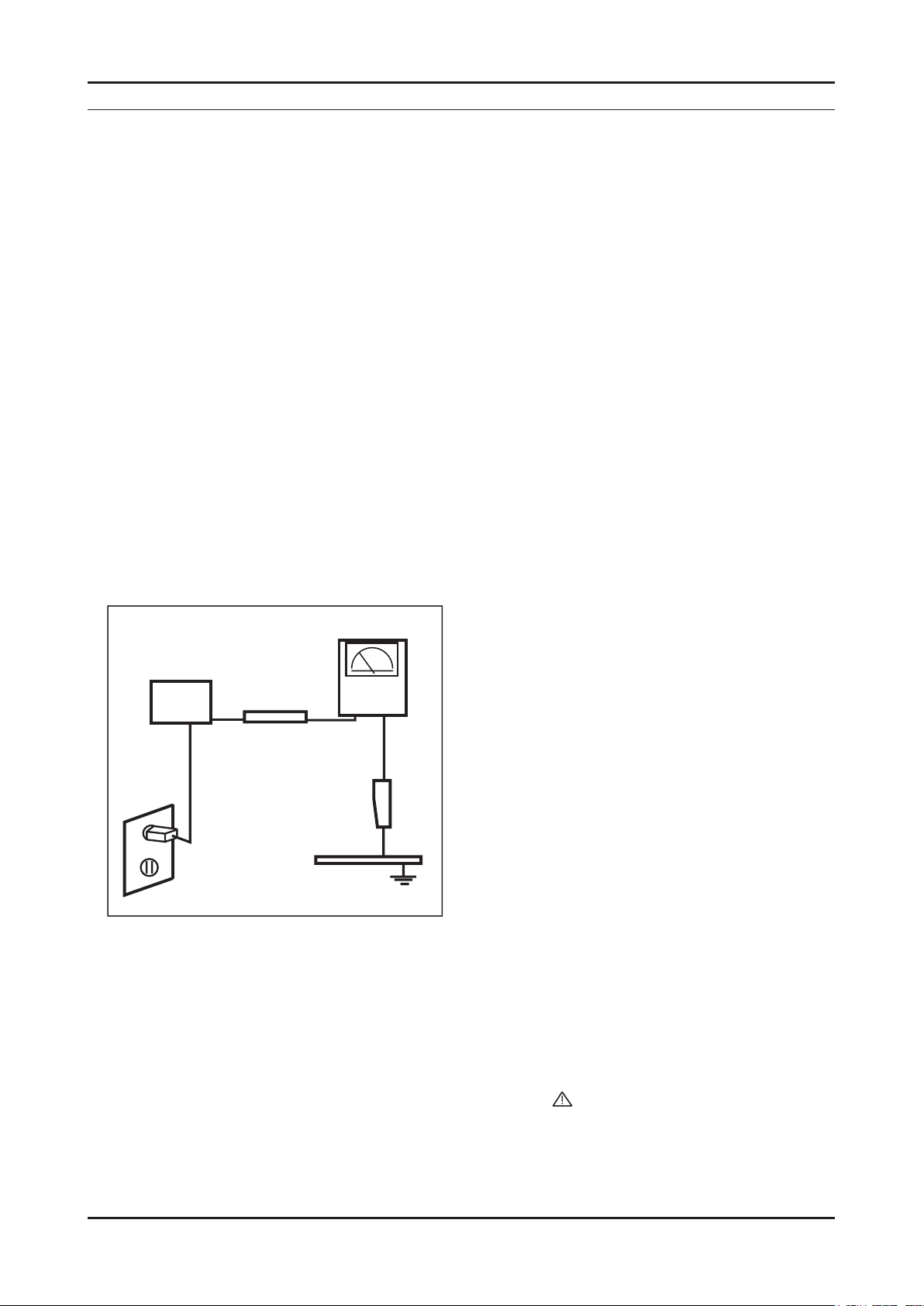
Leakage Current Hot Check (Figure 1-1): 3.
WARNING : Do not use an isolation transformer during this test.
Use a leakage current tester or a metering system that complies with American National Standards Institute (ANSI
C101.1, Leakage Current for Appliances), and Underwriters Laboratories (UL Publication UL1410, 59.7).
(READING SHOULD)
NOT BE ABOVE 0.5mA
DEVICE
UNDER
TEST
2-WIRE CORD
*ALSO TEST WITH
PLUG REVERSED
(USING AC ADAPTER
PLUG AS REQUIRED)
TEST ALL
EXPOSED METAL
SURFACES
LEAKAGE
CURRENT
TESTER
EARTH
GROUND
Figure 1-1. Leakage Current Test Circuit
With the unit completely reassembled, plug the AC line cord directly into a 120V AC outlet. With the unit’s AC switch 4.
rst in the ON position and then OFF, measure the current between a known earth ground (metal water pipe, conduit,
etc.) and all exposed metal parts, including: metal cabinets, screwheads and control shafts.
The current measured should not exceed 0.5 milliamp.
Reverse the power-plug prongs in the AC outlet and repeat the test.
1-1-4. Product Safety Notices
Some electrical and mechanical parts have special safetyrelated characteristics which are often not evident from visual
inspection. The protection they give may not be obtained by replacing them with components rated for higher voltage,
wattage, etc. Parts that have special safety characteristics are identied by
replacement that does not have the same safety characteristics as the recommended replacement part might create
shock, re and/or other hazards. Product safety is under review continuously and new instructions are issued whenever
appropriate.
on schematics and parts lists. A substitute
1-1
Page 5

1-2
1. Precautions
1-2. Servicing Precautions
WARNING: An electrolytic capacitor installed with the wrong polarity might explode.
Caution: Before servicing units covered by this service manual, read and follow the Safety Precautions section of
this manual.
Note: If unforeseen circumstances create conict between the following servicing precautions and any of the
safety precautions, always follow the safety precautions.
1-2-1 General Servicing Precautions
Always unplug the unit’s AC power cord from the AC power source and disconnect the DC Power Jack before 1.
attempting to:
(a) remove or reinstall any component or assembly, (b) disconnect PCB plugs or connectors, (c) connect a test
component in parallel with an electrolytic capacitor.
Some components are raised above the printed circuit board for safety. An insulation tube or tape is sometimes 2.
used. The internal wiring is sometimes clamped to prevent contact with thermally hot components. Reinstall all such
elements to their original position.
After servicing, always check that the screws, components and wiring have been correctly reinstalled. Make sure that 3.
the area around the serviced part has not been damaged.
Check the insulation between the blades of the AC plug and accessible conductive parts (examples: metal panels, 4.
input terminals and earphone jacks).
Insulation Checking Procedure: Disconnect the power cord from the AC source and turn the power switch ON. 5.
Connect an insulation resistance meter (500 V) to theblades of the AC plug.
The insulation resistance between each blade of the AC plug and accessible conductive parts (see above) should be
greater than 1 megohm.
Always connect a test instrument’s ground lead to the instrument chassis ground before connecting the positive lead; 6.
always remove the instrument’s ground lead last.
1-3. Electrostatically Sensitive Devices (ESD) Precautions
Some semiconductor (solid state) devices can be easily damaged by static electricity. Such components are commonly
called Electrostatically Sensitive Devices (ESD). Examples of typical ESD are integrated circuits and some eld-effect
transistors. The following techniques will reduce the incidence of component damage caused by static electricity.
Immediately before handling any semiconductor components or assemblies, drain the electrostatic charge from your 1.
body by touching a known earth ground. Alternatively, wear a discharging wrist-strap device. To avoid a shock hazard,
be sure to remove the wrist strap before applying power to the LED TV.
After removing an ESD-equipped assembly, place it on a conductive surface such as aluminum foil to prevent 2.
accumulation of an electrostatic charge.
Do not use freon-propelled chemicals. These can generate electrical charges sufcient to damage ESDs.3.
Use only a grounded-tip soldering iron to solder or desolder ESDs.4.
Use only an anti-static solder removal device. Some solder removal devices not classied as “anti-static” can generate 5.
electrical charges sufcient to damage ESDs.
Do not remove a replacement ESD from its protective package until you are ready to install it. Most replacement ESDs 6.
are packaged with leads that are electrically shorted together by conductive foam, aluminum foil or other conductive
materials.
Immediately before removing the protective material from the leads of a replacement ESD, touch the protective 7.
material to the chassis or circuit assembly into which the device will be installed.
Caution: Be sure no power is applied to the chassis or circuit and observe all other safety precautions.
Minimize body motions when handling unpackaged replacement ESDs. Motions such as brushing clothes together, 8.
or lifting your foot from a carpeted oor can generate enough static electricity to damage an ESD.
Page 6

1-3
1. Precautions
1-4. Installation Precautions
For safety reasons, more than a people are required for carrying the product.1.
Keep the power cord away from any heat emitting devices, as a melted covering may cause re or electric shock.2.
Do not place the product in areas with poor ventilation such as a bookshelf or closet. The increased internal 3.
temperature may cause re.
Bend the external antenna cable when connecting it to the product. This is a measure to protect it from being exposed 4.
to moisture. Otherwise, it may cause a re or electric shock.
Make sure to turn the power off and unplug the power cord from the outlet before repositioning the product. Also check 5.
the antenna cable or the external connectors if they are fully unplugged. Damage to the cord may cause re or electric
shock.
Keep the antenna far away from any high-voltage cables and install it rmly. Contact with the highvoltage cable or the 6.
antenna falling over may cause re or electric shock.
When installing the product, leave enough space (0.4m) between the product and the wall for ventilation purposes. 7.
A rise in temperature within the product may cause re.
Page 7
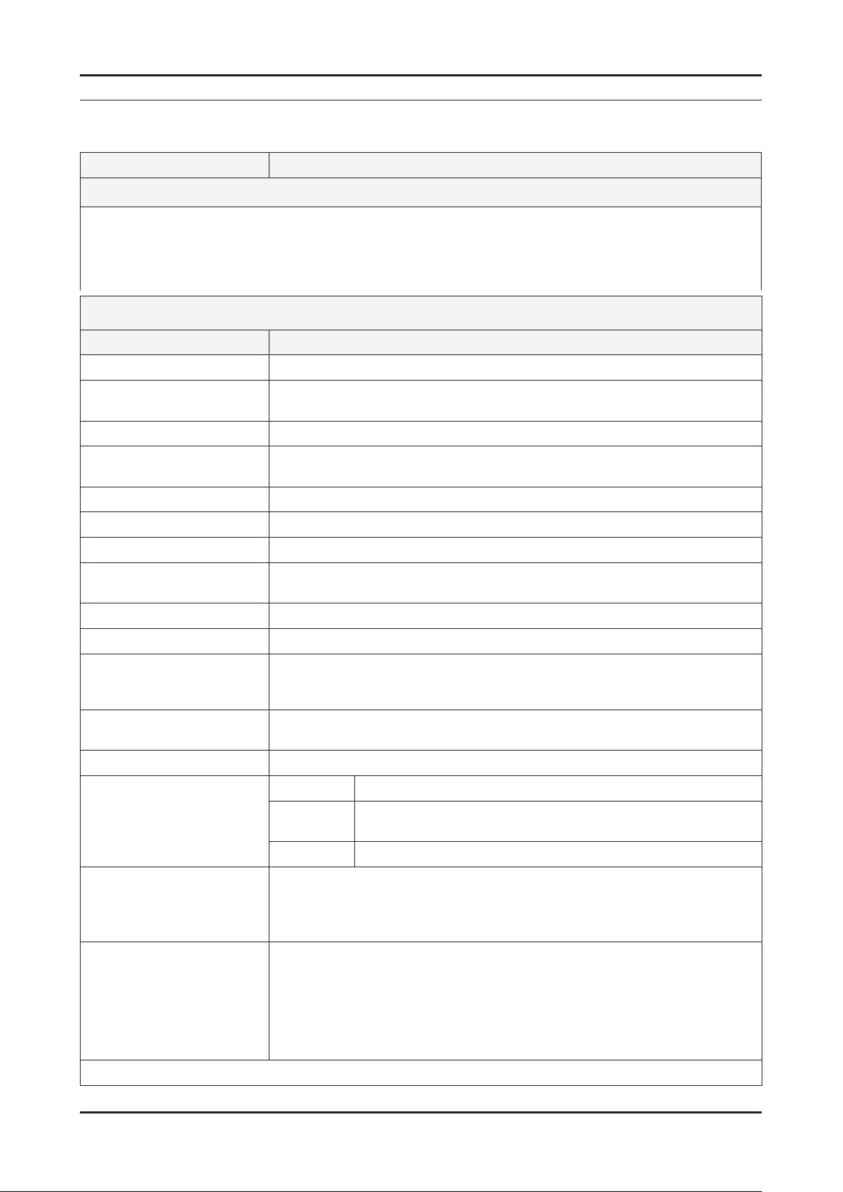
2. Product specications
2-1. Feature & Specications
Model UE32D50** / UE32D55** / UE32D57**
Feature
DTV/ATV (5700 : Satellite), 4-HDMI, 1-Component, 1-A/V, D-SUB, 1-SCART, 2-USB2.0 ሪ
Brightness : 300 cd/m ሪ
High Contrast Ratio : 6,000:1 ሪ
Response Time : 6.5ms ሪ
Item Description
LCD Panel 32 inch FHD
Scanning Frequency Horizontal : 50 kHz ~ 75 kHz (Automatic)
Display Colors 16.7M color
Maximum resolution Horizontal : 1920 Pixels
2
Specications
Vertical : 47 Hz ~ 63 Hz (Automatic)
Vertical : 1080 pixels
2. Product specications
Input Signal Analog 0.7 Vp-p ± 5% positive at 75Ω , internally terminated
Input Sync Signal H/V Separate, TTL, P. or N.
Maximum Pixel Clock rate 80 MHz (Typ 74.25 MHz)
Active Display
Horizontal/Vertical
AC power voltage & Frequency AC 100 V ~ 240 V, 50/60 Hz
Power Consumption Under 80W (Under 0.3 W, Stand by)
Dimensions
Set (W x D x H)
Weight 22.49 Ibs (10.2 kg)_with stand
Stand Weight 6 Ibs (2.74 kg)
TV System Tuning Frequency Synthesize (Refer to detailed Frequency Table)
Environmental Considerations Operating Temperature : 50˚F ~ 104˚F (10˚C ~ 40˚C)
27.50 x 15.47 inches (698.4(H) x 392.85(V) mm)
30.2 x 9.4 x 20.9 inches (768 x 240 x 532.1 mm)_with stand
30.2 x 1.2 x 18.4 inches (768 x 29.9 x 468.2 mm)_without stand
16.45 Ibs (7.46 kg)_without stand
System
Sound BG, DK, L/L’, NICAM, MPEG1, DD, DD+, HE-AAC
Operating Humidity : 10% ~ 80%, non-condensing
Storage temperature : -13˚F ~ 113˚F (-25˚C ~ 45˚C)
Storage Humidity : 5% ~ 95%, non-condensing
DVB-T/C (D5700 : DVB-T/C/S2, D5500 UK : DVB-T2/C), PAL,
SECAM, NT4.43
Audio Spec. - MAX Internal Audio Output Power : Each 10 W (Left/Right)
- BASS Control Range : -8 dB ~ + 8dB
- TREBLE Control Range : -8 dB ~ +8 dB
- Headphone Out : 10 mW MAX
- Output Frequency : RF : 80 Hz ~ 15 kHz
AV/Componet/HDMI : 80 Hz ~ 20 kHz
Note: TruSurround HD, Film Mode, Energy Saving, Anynet+, Allshare (D5500, D5700 : Internet TV)
2-1
Page 8
2-2
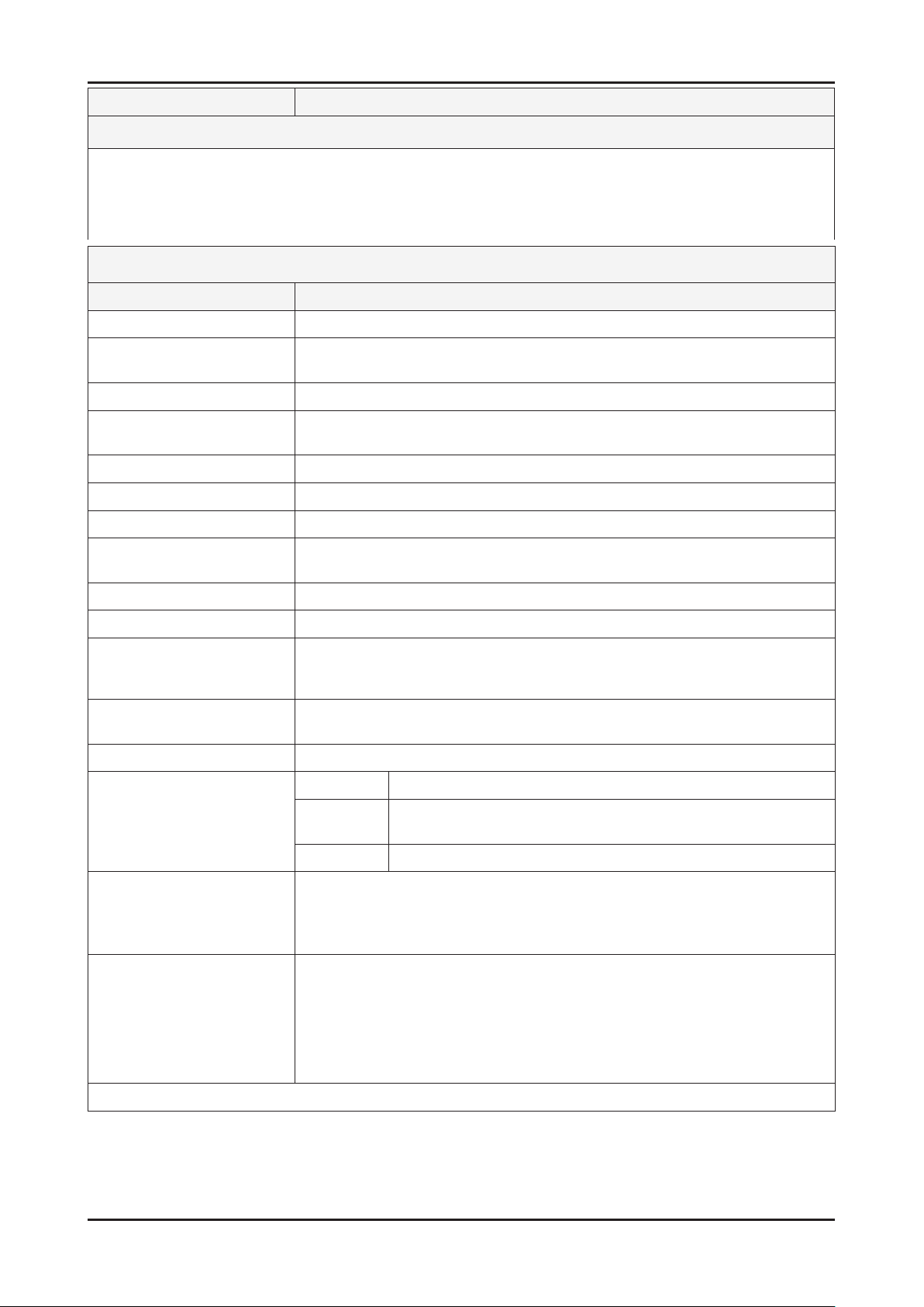
2. Product specications
Model UE37D50** / UE37D55** / UE37D57**
Feature
DTV/ATV (5700 : Satellite), 4-HDMI, 1-Component, 1-A/V, D-SUB, 1-SCART, 2-USB2.0 ሪ
Brightness : 300 cd/m ሪ
2
High Contrast Ratio : 6,000:1 ሪ
Response Time : 9 ms ሪ
Specications
Item Description
LCD Panel 37inch FHD
Scanning Frequency Horizontal : 60 kHz ~ 73 kHz (Automatic)
Vertical : 47 Hz ~ 63 Hz (Automatic)
Display Colors 16.7M color
Maximum resolution Horizontal : 1920 Pixels
Vertical : 1080 pixels
Input Signal Analog 0.7 Vp-p ± 5% positive at 75Ω , internally terminated
Input Sync Signal H/V Separate, TTL, P. or N.
Maximum Pixel Clock rate 82 MHz (Typ 74.25 MHz)
Active Display
Horizontal/Vertical
32.26 x 18.15 inches (819.36(H) x 460.89(V) mm)
AC power voltage & Frequency AC 100 V ~ 240 V, 50/60 Hz
Power Consumption Under 90W (Under 0.3 W, Stand by)
Dimensions
Set (W x D x H)
35.1 x 10.0 x 23.7 inches (890.6 x 255 x 602.1 mm)_with stand
35.1 x 1.2 x 21.2 inches (890.6 x 29.9 x 537.4 mm)_without stand
Weight 22.49 Ibs (10.2 kg)_with stand
16.45 Ibs (7.46 kg)_without stand
Stand Weight 7.23 Ibs (3.28 kg)
TV System Tuning Frequency Synthesize (Refer to detailed Frequency Table)
System
DVB-T/C (D5700 : DVB-T/C/S2, D5500 UK : DVB-T2/C), PAL,
SECAM, NT4.43
Sound BG, DK, L/L’, NICAM, MPEG1, DD, DD+, HE-AAC
Environmental Considerations Operating Temperature : 50˚F ~ 104˚F (10˚C ~ 40˚C)
Operating Humidity : 10% ~ 80%, non-condensing
Storage temperature : -13˚F ~ 113˚F (-25˚C ~ 45˚C)
Storage Humidity : 5% ~ 95%, non-condensing
Audio Spec. - MAX Internal Audio Output Power : Each 10 W (Left/Right)
- BASS Control Range : -8 dB ~ + 8dB
- TREBLE Control Range : -8 dB ~ +8 dB
- Headphone Out : 10 mW MAX
- Output Frequency : RF : 80 Hz ~ 15 kHz
AV/Componet/HDMI : 80 Hz ~ 20 kHz
Note: TruSurround HD, Film Mode, Energy Saving, Anynet+, Allshare (D5500, D5700 : Internet TV)
Page 9
2-3
2. Product specications
Model UE40D50** / UE40D55** / UE40D57**
Feature
DTV/ATV (5700 : Satellite), 4-HDMI, 1-Component, 1-A/V, D-SUB, 1-SCART, 2-USB2.0 ሪ
Brightness : 300 cd/m ሪ
2
High Contrast Ratio : 6,000:1 ሪ
Response Time : 9 ms ሪ
Specications
Item Description
LCD Panel 40inch FHD
Scanning Frequency Horizontal : 48 kHz ~ 75 kHz (Automatic)
Vertical : 48 kHz ~ 75 kHz (Automatic)
Display Colors 16.7M color
Maximum resolution Horizontal : 1920 Pixels
Vertical : 1080 pixels
Input Signal Analog 0.7 Vp-p ± 5% positive at 75Ω , internally terminated
Input Sync Signal H/V Separate, TTL, P. or N.
Maximum Pixel Clock rate 80 MHz (Typ 74.25 MHz)
Active Display
Horizontal/Vertical
34.87 x 19.61 inches (885.6 (H) x 498.15 (V) mm)
AC power voltage & Frequency AC 100 V ~ 240 V, 50/60 Hz
Power Consumption Under 100 W (Under 0.3 W, Stand by)
Dimensions
Set (W x D x H)
37.6 x 10.0 x 25.1 inchs (955.8 x 255.0 x 638.5 mm)_with stand
37.6 x 1.2 x 22.6 inchs (955.8 x 29.9 x 574.0 mm)_without stand
Weight 31.7 Ibs (14.36 kg)_with stand
24.4 Ibs (11.08 kg)_without stand
Stand Weight 7.2 Ibs (3.28 kg)
TV System Tuning Frequency Synthesize (Refer to detailed Frequency Table)
System
DVB-T/C (D5700 : DVB-T/C/S2, D5500 UK : DVB-T2/C), PAL,
SECAM, NT4.43
Sound BG, DK, L/L’, NICAM, MPEG1, DD, DD+, HE-AAC
Environmental Considerations Operating Temperature : 50˚F ~ 104˚F (10˚C ~ 40˚C)
Operating Humidity : 10% ~ 80%, non-condensing
Storage temperature : -13˚F ~ 113˚F (-25˚C ~ 45˚C)
Storage Humidity : 5% ~ 95%, non-condensing
Audio Spec. - MAX Internal Audio Output Power : Each 10 W (Left/Right)
- BASS Control Range : -8 dB ~ + 8dB
- TREBLE Control Range : -8 dB ~ +8 dB
- Headphone Out : 10 mW MAX
- Output Frequency : RF : 80 Hz ~ 15 kHz
AV/Componet/HDMI : 80 Hz ~ 20 kHz
Note: TruSurround HD, Film Mode, Energy Saving, Anynet+, Allshare (D5500, D5700 : Internet TV)
Page 10
2-4
2. Product specications
Model UE46D50** / UE46D55** / UE46D57**
Feature
DTV/ATV (5700 : Satellite), 4-HDMI, 1-Component, 1-A/V, D-SUB, 1-SCART, 2-USB2.0 ሪ
Brightness : 300 cd/m ሪ
2
High Contrast Ratio : 6,000:1 ሪ
Response Time : 5.5 ms ሪ
Specications
Item Description
LCD Panel 46 inch FHD
Scanning Frequency Horizontal : 45 kHz ~ 75 kHz (Automatic)
Vertical : 48 Hz ~ 65 Hz (Automatic)
Display Colors 16.7M color
Maximum resolution Horizontal : 1920 Pixels
Vertical : 1080 pixels
Input Signal Analog 0.7 Vp-p ± 5% positive at 75Ω , internally terminated
Input Sync Signal H/V Separate, TTL, P. or N.
Maximum Pixel Clock rate 80 MHz (Typ 74.25 MHz)
Active Display
Horizontal/Vertical
40.08 x 22.55 inches (1018.08 (H) x 572.67 (V) mm)
AC power voltage & Frequency AC 100 V ~ 240 V, 50/60 Hz
Power Consumption Under 150 W (Under 0.3 W, Stand by)
Dimensions
Set (W x D x H)
43.0 x 10.8 x 28.1 inchs (1091.8 x 275.0 x 714.8 mm)_with stand
43.0 x 1.2 x 25.6 inchs (1091.8 x 29.9 x 650.4 mm)_without stand
Weight 38.14 Ibs (17.3 kg)_with stand
30.29 Ibs (13.74 kg)_without stand
Dimensions
Stand (W x D x H)
19.5 x 10.8 x 7.1 inchs (495 x 275 x 181 mm)
Weight (Stand) 7.85 Ibs (3.56 kg)
TV System Tuning Frequency Synthesize (Refer to detailed Frequency Table)
System
DVB-T/C (D5700 : DVB-T/C/S2, D5500 UK : DVB-T2/C), PAL,
SECAM, NT4.43
Sound BG, DK, L/L’, NICAM, MPEG1, DD, DD+, HE-AAC
Environmental Considerations Operating Temperature : 50˚F ~ 104˚F (10˚C ~ 40˚C)
Operating Humidity : 10% ~ 80%, non-condensing
Storage temperature : -13˚F ~ 113˚F (-25˚C ~ 45˚C)
Storage Humidity : 5% ~ 95%, non-condensing
Audio Spec. - MAX Internal Audio Output Power : Each 10 W (Left/Right)
- BASS Control Range : -8 dB ~ + 8dB
- TREBLE Control Range : -8 dB ~ +8 dB
- Headphone Out : 10 mW MAX
- Output Frequency : RF : 80 Hz ~ 15 kHz
AV/Componet/HDMI : 80 Hz ~ 20 kHz
Note: TruSurround HD, Film Mode, Energy Saving, Anynet+, Allshare (D5500, D5700 : Internet TV)
Page 11

2-5
2. Product specications
Model UE19D40**
Feature
DTV/ATV, 2-HDMI, 1-Component, 1-A/V, D-SUB, 1-SCART, 2-USB2.0, CI Slot ሪ
Brightness : 250 cd/m ሪ
2
High Contrast Ratio : 1,000:1 ሪ
Response Time : 5 ms ሪ
Specications
Item Description
LCD Panel 19 inch HD
Scanning Frequency Horizontal : 37.13 kHz ~ 59.25 kHz (Automatic)
Vertical : 47 Hz ~ 75 Hz (Automatic)
Display Colors 16.7M color
Maximum resolution Horizontal : 1366 Pixels
Vertical : 768 Pixels
Input Signal Analog 0.7 Vp-p ± 5% positive at 75Ω , internally terminated
Input Sync Signal H/V Separate, TTL, P. or N.
Maximum Pixel Clock rate 90.42 MHz (Typ 72.33 MHz)
Active Display
Horizontal/Vertical
16.13 x 9.07 inches (409.8 (H) x 230.4 (V) mm)
AC power voltage & Frequency AC 100V ~ 240V, 50/60 Hz
Power Consumption Under 30 W (Under 0.3 W, Stand by)
Dimensions
Set (W x D x H)
17.9 x 5.7 x 13.4 inches (455.4 x 144.8 x 339.5 mm)_with stand
17.9 x 1.2 x 11.2 inches (455.4 x 29.9 x 285.6 mm)_without stand
Weight 7.50 Ibs (3.4 kg)_with stand
6.83 Ibs (3.1 kg)_without stand
Dimensions
Stand (W x D x H)
10.5 x 5.7 x 3.2 inchs (265.8 x 144.8 x 81.4 mm)
Weight (Stand) 0.66 Ibs (0.3 kg)
TV System Tuning Frequency Synthesize (Refer to detailed Frequency Table)
System DVB-T/C, PAL, SECAM, NT4.43
Sound BG, DK, L/L’, NICAM, MPEG1, DD, DD+, HE-AAC
Environmental Considerations Operating Temperature : 50˚F ~ 104˚F (10˚C ~ 40˚C)
Operating Humidity : 10% ~ 80%, non-condensing
Storage temperature : -13˚F ~ 113˚F (-25˚C ~ 45˚C)
Storage Humidity : 5% ~ 95%, non-condensing
Audio Spec. - MAX Internal Audio Output Power : Each 3 W (Left/Right)
- BASS Control Range : -8 dB ~ + 8dB
- TREBLE Control Range : -8 dB ~ +8 dB
- Headphone Out : 10 mW MAX
- Output Frequency : RF : 80 Hz ~ 15 kHz
AV/Componet/HDMI : 80 Hz ~ 20 kHz
Note: Dolby Digital +, Game Mode, Film Mode, Energy Saving, Anynet+
Page 12
2-6
2. Product specications
Model UE32D40**
Feature
DTV/ATV, 4-HDMI, 1-Component, 1-A/V, D-SUB, 1-SCART, 1-USB2.0 ሪ
Brightness : 450 cd/m ሪ
2
High Contrast Ratio : 3,500:1 ሪ
Response Time : 8.5 ms ሪ
Specications
Item Description
LCD Panel 32 inch HD
Scanning Frequency Horizontal : 37 kHz ~ 59.25 kHz (Automatic)
Vertical : 47 Hz ~ 75 Hz (Automatic)
Display Colors 16.7M color
Maximum resolution Horizontal : 1366 Pixels
Vertical : 768 Pixels
Input Signal Analog 0.7 Vp-p ± 5% positive at 75Ω , internally terminated
Input Sync Signal H/V Separate, TTL, P. or N.
Maximum Pixel Clock rate 90.42 MHz (Typ 72.33 MHz)
Active Display
Horizontal/Vertical
27.47 x 15.44 inches (697.685 (H) x 392.256 (V) mm)
AC power voltage & Frequency AC 100V ~ 240V, 50/60 Hz
Power Consumption Under 90 W (Under 0.3 W, Stand by)
Dimensions
Set (W x D x H)
30.1 x 8.8 x 20.7 inchs (763.6 x 222.7 x 525.1 mm)_with stand
30.1 x 8.8 x 20.8 inchs (763.6 x 222.7 x 527.1 mm)_with stand (UD4010)
30.1 x 1.2 x 18.2 inchs (763.6 x 29.9 x 463.1 mm)_without stand
Weight 19.8 Ibs (9.0 kg)_with stand
15.4 Ibs (7.0 kg)_without stand
Dimensions
Stand (W x D x H)
17.8 x 8.8 x 6.1 inchs (452.2 x 222.7 x 154.2 mm)
17.8 x 8.8 x 6.15 inchs (452.2 x 222.7 x 156.2 mm) (UD4010)
Weight (Stand) 4.4 Ibs (2.0 kg)
TV System Tuning Frequency Synthesize (Refer to detailed Frequency Table)
System DVB-T/C, PAL, SECAM, NT4.43
Sound BG, DK, L/L’, NICAM, MPEG1, DD, DD+, HE-AAC
Environmental Considerations Operating Temperature : 50˚F ~ 104˚F (10˚C ~ 40˚C)
Operating Humidity : 10% ~ 80%, non-condensing
Storage temperature : -13˚F ~ 113˚F (-25˚C ~ 45˚C)
Storage Humidity : 5% ~ 95%, non-condensing
Audio Spec. - MAX Internal Audio Output Power : Each 10 W (Left/Right)
- BASS Control Range : -8 dB ~ + 8dB
- TREBLE Control Range : -8 dB ~ +8 dB
- Headphone Out : 10 mW MAX
- Output Frequency : RF : 80 Hz ~ 15 kHz
AV/Componet/HDMI : 80 Hz ~ 20 kHz
Note: Dolby Digital +, Game Mode, Film Mode, Energy Saving, Anynet+
Page 13
2-7
2. Product specications
Model UE22D50**
Feature
DTV/ATV, 1-HDMI, 1-Component, 1-A/V, D-SUB, 1-SCART, 1-USB2.0 ሪ
Brightness : 250 cd/m ሪ
2
High Contrast Ratio : 1,000:1 ሪ
Response Time : 5 ms ሪ
Specications
Item Description
LCD Panel 22 inch FHD
Scanning Frequency Horizontal : 60 kHz ~ 73 kHz (Automatic)
Vertical : 50 Hz ~ 75 Hz (Automatic)
Display Colors 16.7M color
Maximum resolution Horizontal : 1920 Pixels
Vertical : 1080 Pixels
Input Signal Analog 0.7 Vp-p ± 5% positive at 75Ω , internally terminated
Input Sync Signal H/V Separate, TTL, P. or N.
Maximum Pixel Clock rate 90 MHz (Typ 75 MHz)
Active Display
Horizontal/Vertical
18.77 x 10.56 inches (476.64 (H) x 268.11 (V) mm)
AC power voltage & Frequency AC 100V ~ 240V, 50/60 Hz
Power Consumption Under 40 W (Under 0.3 W, Stand by)
Dimensions
Set (W x D x H)
20.6 x 5.7 x 14.8 inchs (522 x 144.8 x 377 mm)_with stand
20.6 x 1.2 x 12.7 inchs (522 x 29.9 x 323.1 mm)_without stand
Weight 8.6 Ibs (3.9 kg)_with stand
7.9 Ibs (3.6 kg)_without stand
Dimensions
Stand (W x D x H)
10.5 x 5.7 x 3.2 inchs (265.8 x 144.8 x 81.4 mm)
Weight (Stand) 0.7 Ibs (0.3 kg)
TV System Tuning Frequency Synthesize (Refer to detailed Frequency Table)
System DVB-T/C, PAL, SECAM, NT4.43
Sound BG, DK, L/L’, NICAM, MPEG1, DD, DD+, HE-AAC
Environmental Considerations Operating Temperature : 50˚F ~ 104˚F (10˚C ~ 40˚C)
Operating Humidity : 10% ~ 80%, non-condensing
Storage temperature : -13˚F ~ 113˚F (-25˚C ~ 45˚C)
Storage Humidity : 5% ~ 95%, non-condensing
Audio Spec. - MAX Internal Audio Output Power : Each 3 W (Left/Right)
- BASS Control Range : -8 dB ~ + 8dB
- TREBLE Control Range : -8 dB ~ +8 dB
- Headphone Out : 10 mW MAX
- Output Frequency : RF : 80 Hz ~ 15 kHz
AV/Componet/HDMI : 80 Hz ~ 20 kHz
Note: Dolby Digital +, Game Mode, Film Mode, Energy Saving, Anynet+
Page 14

2-8
2. Product specications
Model UE27D50**
Feature
DTV/ATV, 2-HDMI, 1-Component, 1-A/V, D-SUB, 1-SCART, 1-USB2.0 ሪ
Brightness : 450 cd/m ሪ
2
High Contrast Ratio : 3,000:1 ሪ
Response Time : 6.5 ms ሪ
Specications
Item Description
LCD Panel 27inch FHD
Scanning Frequency Horizontal : 54.2 kHz ~ 83.8 kHz (Automatic)
Vertical : 49 Hz ~ 75 Hz (Automatic)
Display Colors 16.7M color
Maximum resolution Horizontal : 1920 Pixels
Vertical : 1080 Pixels
Input Signal Analog 0.7 Vp-p ± 5% positive at 75Ω , internally terminated
Input Sync Signal H/V Separate, TTL, P. or N.
Maximum Pixel Clock rate 83 MHz (Typ 67.3 MHz)
Active Display
Horizontal/Vertical
23.53 x 13.23 inches (597.6 (H) x 336.15 (V) mm)
AC power voltage & Frequency AC 100V ~ 240V, 50/60 Hz
Power Consumption Under 65 W (Under 0.3 W, Stand by)
Dimensions
Set (W x D x H)
25.4 x 6.9 x 17.8 inchs (645 x 176.3 x 453.3 mm)_with stand
25.4 x 6.9 x 18.0 inchs (645 x 176.3 x 456.5 mm)_with stand (UD5010)
25.4 x 1.2 x 15.5 inchs (645 x 29.9 x 393.2 mm)_without stand
Weight 11.5 Ibs (5.2 kg)_with stand
10.1 Ibs (4.6 kg)_without stand
Dimensions
Stand (W x D x H)
13.6 x 6.9 x 4.4 inchs (346.1 x 176.3 x 113 mm)
13.6 x 6.9 x 4.6 inchs (346.1 x 176.3 x 116.2 mm) (UD5010)
Weight (Stand) 1.4 Ibs (0.6 kg)
TV System Tuning Frequency Synthesize (Refer to detailed Frequency Table)
System DVB-T/C, PAL, SECAM, NT4.43
Sound BG, DK, L/L’, NICAM, MPEG1, DD, DD+, HE-AAC
Environmental Considerations Operating Temperature : 50˚F ~ 104˚F (10˚C ~ 40˚C)
Operating Humidity : 10% ~ 80%, non-condensing
Storage temperature : -13˚F ~ 113˚F (-25˚C ~ 45˚C)
Storage Humidity : 5% ~ 95%, non-condensing
Audio Spec. - MAX Internal Audio Output Power : Each 5 W (Left/Right)
- BASS Control Range : -8 dB ~ + 8dB
- TREBLE Control Range : -8 dB ~ +8 dB
- Headphone Out : 10 mW MAX
- Output Frequency : RF : 80 Hz ~ 15 kHz
AV/Componet/HDMI : 80 Hz ~ 20 kHz
Note: Dolby Digital +, Game Mode, Film Mode, Energy Saving, Anynet+
Page 15
2-9
2. Product specications
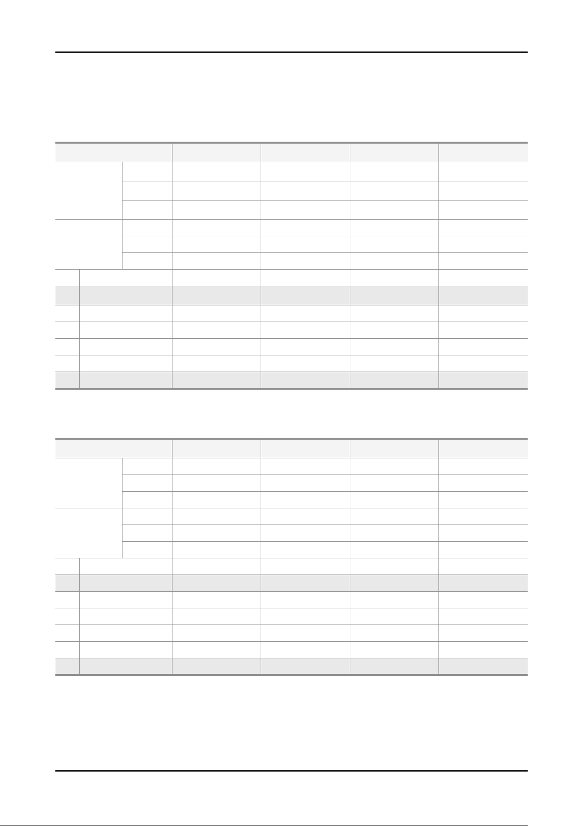
2-2. Detail Factory Option
If you replace the main board with new one, please change the factory option as well. ※
The options you must change are "Type" and "Front Color".
2-2-1. UD5XXX
Model Name UE32D50**PW UE37D50**PW UE40D50**PW UE46D50**PW
CHILIN(CMI)
AML
BN07-00989A
BN95-00436A
LD320BGC-C1
LTJ320HN01-V
Panel
Vendor
CODE
SPEC
Vendor SEM DYREL DYREL SEM
CHILIN(AUO)
BN07-01002A
LD370BGB-C1
CHILIN(CMI)
AML
BN07-00990A
BN95-00434A
LD400BGC-C1
LTJ400HM03-V
CHILIN(CMI)
BN07-00991A
LD460BGC-C1
SMPS
1 Factory Reset - - - -
2 Type
3 Local set EU EU EU EU
4 Model UD5000 UD5000 UD5000 UD5000
5 TUNER SEC_TC SEC_TC SEC_TC SEC_TC
6 Ch Table - - - -
7 Front Color U-T-C-BLK U-T-C-BLK U-T-C-BLK U-T-C-BLK
CODE BN44-00460A BN44-00422B BN44-00422B BN44-00422A
SPEC PSLF800A03A PD46A0_BDY PD46A0_BDY PSLF121A03A
32P6UFOE
32A6UFOE
37P6UFOE
40P6UFOE
40A6UFOE
46P6UFOE
2-2-2. UD55XX
Model Name UE32D55**RW UE37D55**RW UE40D55**RW UE46D55**RW
Vendor CHILIN(CMI) CHILIN(AUO) CHILIN(CMI) CHILIN(CMI)
Panel
CODE BN07-00989A BN07-01002A BN07-00990A BN07-00991A
SPEC LD320BGC-C1 LD370BGB-C1 LD400BGC-C1 LD460BGC-C1
Vendor SEM DYREL DYREL SEM
SMPS
1 Factory Reset - - - -
2 Type 32P6UFOE 37P6UFOE 40P6UFOE 46P6UFOE
3 Local set EU EU EU EU
4 Model UD5500 UD5500 UD5500 UD5500
5 TUNER SEC_TC SEC_TC SEC_TC SEC_TC
6 Ch Table - - - -
7 Front Color U-T-R-BLK U-T-R-BLK U-T-R-BLK U-T-R-BLK
CODE BN44-00460A BN44-00422B BN44-00422B BN44-00422A
SPEC PSLF800A03A PD46A0_BDY PD46A0_BDY PSLF121A03A
Page 16
2-10
2. Product specications
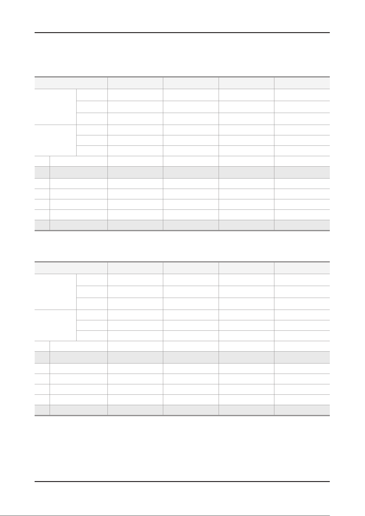
If you replace the main board with new one, please change the factory option as well. ※
The options you must change are "Type" and "Front Color".
2-2-3. UD57XX
Model Name UE32D57**RS UE37D57**RS UE40D57**RS UE46D57**RS
CHILIN(CMI)
AML
BN07-00989A
BN95-00436A
LD320BGC-C1
LTJ320HN01-V
Panel
Vendor
CODE
SPEC
Vendor SEM DYREL DYREL SEM
CHILIN(AUO)
BN07-01002A
LD370BGB-C1
CHILIN(CMI)
AML
BN07-00990A
BN95-00434A
LD400BGC-C1
LTJ400HM03-V
CHILIN(CMI)
BN07-00991A
LD460BGC-C1
SMPS
1 Factory Reset - - - -
2 Type
3 Local set EU EU EU EU
4 Model UD5700 UD5700 UD5700 UD5700
5 TUNER SEC_TCS SEC_TCS SEC_TCS SEC_TCS
6 Ch Table - - - -
7 Front Color U-T-R-BLK U-T-R-BLK U-T-R-BLK U-T-R-BLK
CODE BN44-00460A BN44-00422B BN44-00422B BN44-00422A
SPEC PSLF800A03A PD46A0_BDY PD46A0_BDY PSLF121A03A
32P6UFOE
32A6UFOE
37P6UFOE
40P6UFOE
40A6UFOE
46P6UFOE
2-2-4. UD40XX_UD50XXX(Small inch)
Model Name UE19D40**NW UE32D40**NW UE22D50**NW UE27D50**NW
CHILIN (CMI)
AML
BN07-00988A
BN95-00437A
LD320AGC-C1
LTJ320AP01-V
AUO SEC
BN07-00937A BN07-00959A
M215HW01 VB LTM270HT03-V
Panel
Vendor SEC
CODE BN07-00898A
SPEC LTM185AT04-V
Vendor DYREL SEM DYREL DYREL
SMPS
1 Factory Reset - - - -
2 Type 19A6TH0C
3 Local set EU EU EU EU
4 Model UD4000 UD4000 UD5000 UD5000
5 TUNER SEC_TC SEC_TC SEC_TC SEC_TC
6 Ch Table - - - -
7 Front Color U-S-BK U-S-BK U-T-C-BLK U-T-C-BLK
CODE BN44-00448A BN44-00421A BN44-00448A BN44-00450A
SPEC PD22A0_BDY PSLF800A03A PD22A0_BDY PD27A0_BDY
32P6AHOE
32A6AHOE
22L6TFOE 27A6TFOE
Page 17
2-11
2. Product specications
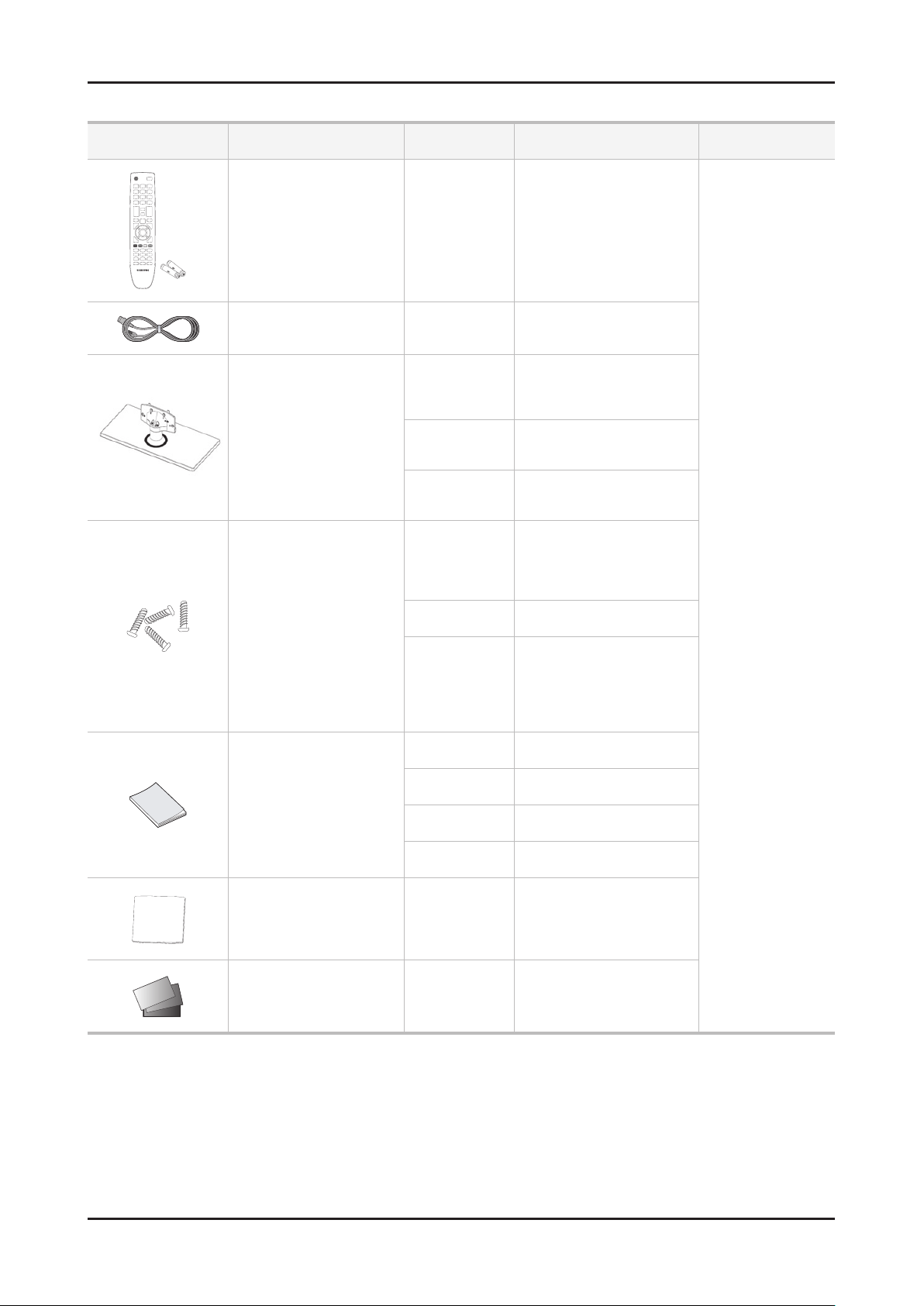
2-3. Accessories
Product Description Mode Code. No Remark
Remote Control & Batteries
(AAA x 2)
Power Cord ALL 3903-000525
Stand
Screw
6001-002621 : M4 x L8
6003-001782 : M4 x L12
ALL
5000/5500/5700
5000_small
4000
5000/5500/5700
5000_small 22"/27" : 6003-001782
4000
32" : BN90-03128*
37" /40" : BN90-03129*
46" : BN90-03130*
22" : BN90-03280B
27" : BN90-03282C
19" : BN90-03280B
32" : BN90-03283C
6003-001782
(G/STAND+C/STAND)
6001-002621
(G/STAND+B/S/LINK)
19" : 6003-001782
32" : 6003-001782
(G/STAND+C/STAND)
6001-002621
(G/STAND+B/S/LINK)
AA59-00508A
4301-000121
Samsung Electronics
Service center
5000 BN68-03432A
5500 BN68-03404A
Quick Start Guide
5700 BN68-03506F
4000 BN68-03426A
Cleaning Cloth ALL BN63-01798B
Warranty Card / Registration
Card / Safety Guide Manual
(Not available in all locations)
ALL
BN68-00514K
BN68-03019A
Page 18
2-12
2. Product specications
2-4. New Features explanation
2-4-1. Anynet+
What is Anynet+?
Anynet+ is a function that enables you to control all connected Samsung devices that support Anynet+ with your
Samsung TV’s remote. The Anynet+ system can be used only with Samsung devices that have the Anynet+ feature.
To be sure your Samsung device has this feature, check if there is an Anynet+ logo on it.
N For the method of connecting external devices, refer to the supported user manual.
N NOTE
●Connect the Optical cable between the DIGITAL AUDIO OUT (OPTICAL) jack on your TV and the Digital Audio Input
on the Home Theatre.
● When following the connection above, the Optical jack only outputs 2 channel audio. You will only hear sound from
the Home Theatre’s Front Left and Right speakers and the subwoofer. If you want to hear 5.1 channel audio, connect
the DIGITAL AUDIO OUT (OPTICAL) jack on the DVD / Satellite Box (i.e. Anynet Device 1 or 2) directly to the
Amplier or Home Theatre, not the TV.
● You can connect only one Home Theatre.
● You can connect an Anynet+ device using the HDMI cable. Some HDMI cables may not support Anynet+ functions.
● Anynet+ works when the AV device supporting Anynet+ is in the standby or on status.
● Anynet+ supports up to 12 AV devices in total. Note that you can connect up to 3 devices of the same type.
TOOLST
Anynet+ Menu
The Anynet+ menu changes depending on the type and status of the Anynet+ devices connected to the TV.
Anynet+ Menu Description
View TV Changes Anynet+ mode to TV broadcast mode.
Device List Shows the Anynet+ device list.
(device_name) MENU
(device_name) TOOLS
(device_name) Title Menu
Recording: (*recorder)
Stop Recording: (*recorder) Stops recording.
Receiver Sound is played through the receiver.
If more than one recording device is connected, they are displayed as (*recorder) and if only one recording device is
connected, it will be represented as (*device_name).
Shows the connected device menus. E.g. If a DVD recorder is connected, the disc
menu of the DVD recorder will appear.
Shows the play menu of the connected device. E.g. If a DVD recorder is connected,
the play menu of the DVD recorder will appear.
Shows the title menu of the connected device. E.g. If a DVD recorder is connected, the
title menu of the DVD recorder will appear.
N Depending on the device, this menu may not be available.
Starts recording immediately using the recorder. (This is only available for devices that
support the recording function.)
Setting Up Anynet+
► Anynet+ (HDMI-CEC)
Anynet+ (HDMI-CEC) (Off / On): To use the Anynet+ Function, Anynet+ (HDMI-CEC) must be set to On.
N When the Anynet+ (HDMI-CEC) function is disabled, all the Anynet+ related operations are deactivated.
Auto Turn Off (No / Yes): Setting an Anynet+ Device to turn off automatically when the TV is turned off.
N If Auto Turn Off is set to Yes, running external devices will turn off at the same time as the TV powers off.
However, a device may not turn off if recording is in progress.
N May not be enabled depending on the device.
Page 19

2-13
2. Product specications
Switching between Anynet+ Devices
Press the TOOLS button, then select 1. Anynet+ (HDMI-CEC).
Anynet+ devices connected to the TV are listed in Device List.2.
N If you cannot nd a device you want, press the A button to refresh the list.
Select a device and press the ENTERE3. E button. You can switch to the selected device.
N Only when you set Anynet+ (HDMI-CEC) to On in the System menu, the Device List menu appears.
● Switching to the selected device may take up to 2 minutes. You cannot cancel the operation during the
switching operation.
● If you have selected external input mode by pressing the SOURCE button, you cannot use the Anynet+
function. Make sure to switch to an Anynet+ device by using the Device List.
Recording
You can make a recording of a TV Programme using a Samsung recorder.
Select 1. Recording.
N When there are more than two recording devices
N You can record the source streams by selecting Recording: (device_name).
N Pressing the ∏(REC) button will record whatever you are currently watching. If you are watching video from
N Before recording, check whether the antenna jack is properly connected to the recording device. To properly
● When multiple recording devices are connected, the recording devices are listed. Select one recording
device in the Device List.
● When the recording device is not displayed, select Device List and press the A button to searchdevices.
Press the 2. EXIT button to exit.
another device, the video from the device is recorded.
connect an antenna to a recording device, refer to the recording device’s users manual.
Listening through a Receiver
You can listen to sound through a receiver (i.e Home Theatre) instead of the TV speaker.
Select 1. Receiver and set to On.
Press the 2. EXIT button to exit.
N If your receiver supports audio only, it may not appear in the device list.
N The receiver will work when you have properly connected the optical in jack of the receiver to the DIGITAL
AUDIO OUT (OPTICAL) jack of the TV.
N When the receiver (i.e Home Theatre) is set to On, you can hear sound output from the TV’s Optical jack.
When the TV is displaying a DTV (air) signal, the TV will send out 5.1 channel sound to the receiver. When
the source is a digital component such as a DVD and is connected to the TV via HDMI, only 2 channel sound
will be heard from the receiver.
N NOTE
● You can only control Anynet+ devices using the TV remote control, not the buttons on the TV.
● The TV remote control may not work under certain conditions. If this occurs, reselect the Anynet+ device.
● The Anynet+ functions do not operate with other manufacturers’ products.
Page 20

2-14
2. Product specications
Troubleshooting for Anynet+
Problem Possible Solution
Anynet+ does not work.
Anynet+ does not work.
I want to start Anynet+.
I want to exit Anynet+.
The message
"Connecting to Anynet+
device..."appears on the
screen.
The Anynet+ device does not
play.
The connected device is not
displayed.
The TV Programme cannot be
recorded.
The TV sound is not output
through the receiver.
Check if the device is an Anynet+ device. The Anynet+ system supports Anynet+ •
devices only.
Only one receiver (home theatre) can be connected.•
Check if the Anynet+ device power cord is properly connected.•
Check the Anynet+ device’s Video/Audio/HDMI cable connections.•
Check whether •
Check whether the TV remote control is in •
Anynet+ (HDMI-CEC) is set to On in the System menu.
TV mode.
Check whether the remote control is Anynet+ compatible.•
Anynet+ does not work in certain situations. (Searching channels, operating •
Downloads or Plug & Play (initial setup), etc.)
My
When connecting or removing the HDMI cable, please make sure to search devices •
again or turn your TV off and on again.
Check if the Anynet+ Function of Anynet+ device is set on.•
Check if the Anynet+ device is properly connected to the TV and check if the •
Anynet+(HDMI-CEC) is set to On in the System menu.
Press the TOOLS button to display the Anynet+ menu and select a menu you want.•
View TV in the Anynet+ menu.
Select •
Press the SOURCE button on the TV remote control and select a device other than •
Anynet+ devices.
Press • < CH >, CH LIST , PRE-CH, and FAV.CH to change the TV mode. (Note
that the channel button operates only when a tuner-embedded Anynet+ device is not
connected.)
You cannot use the remote control when you are conguring Anynet+ or switching to •
a view mode.
Use the remote control when the Anynet+ setting or switching to view mode is •
complete.
You cannot use the play function when •
Plug & Play (initial setup) is in progress.
Check whether or not the device supports Anynet+ functions.•
Check whether or not the HDMI cable is properly connected.•
Check whether •
Anynet+ (HDMI-CEC) is set to On in the System menu.
Search Anynet+ devices again.•
You can connect an Anynet+ device using the HDMI cable only. Some HDMI cables •
may not support Anynet+ functions.
If it is terminated by an abnormal situation such as disconnecting the HDMI cable or •
power
cord or a power failure, please repeat the device scan.
Check whether the antenna jack on the recording device is properly connected.•
Connect the optical cable between TV and the receiver.•
Page 21
2-15
2. Product specications
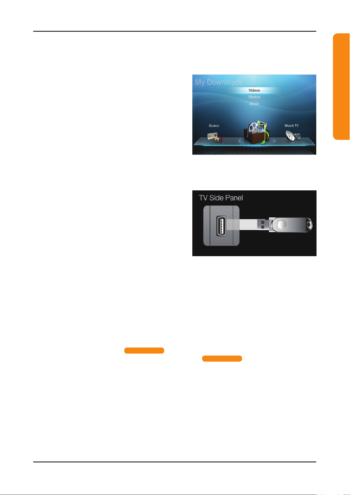
2-4-2. My Contents
Using the My Contents
Enjoy photos, music and/or movie files saved on a USB Mass Storage Class (MSC) device and/or your PC.
Press the 1. CONTENT button to select My Contents.
Press 2. u/d button to select desired menu (Videos,
Photos, Music), then press the ENTERE button.
* It may differ depending on the model.
Connecting a USB Device
Turn on your TV.1.
Connect a USB device containing photo, music and/or 2.
movie les to the USB jack on the side of the TV.
When USB is connected to the TV, popup window 3.
appears. Then you can select Connected Device.
For LED 4000(19" / 32")_5000(22" / 27") series
* It may differ depending on the model.
N It might not work properly with unlicensed multimedia les.
N Need-to-Know List before using My Contents.
MTP (Media Transfer Protocol) is not supported.•
The le system supports FAT16, FAT32 and NTFS.•
Certain types of USB Digital camera and audio devices may not be compatible with this TV.•
• My Contents only supports USB Mass Storage Class (MSC) devices. MSC is a Mass Storage Class Bulk-Only
Transport device. Examples of MSC are Thumb drives, Flash Card Readers and USB HDD (USB HUB are not
supported). Devices should be connected directly to the TV’s USB port.
Before connecting your device to the TV, please back up your les to prevent them from damage or loss of data. •
SAMSUNG is not responsible for any data le damage or data loss.
USB (HDD) is not supported. •
Connect a USB HDD to the dedicated port, USB 1 (HDD) port. •
Do not disconnect the USB device while it is loading.•
The higher the resolution of the image, the longer it takes to display on the screen.•
The maximum supported JPEG resolution is 15360X8640 pixels.•
For unsupported or corrupted les, the “Not Supported File Format” message is displayed.•
If the les are sorted by Basic View, up to 1000 les can be displayed in each folder.•
MP3 les with DRM that have been downloaded from a non-free site cannot be played. Digital Rights •
Management (DRM) is a technology that supports the creation, distribution and management of the content
in an integrated and comprehensive way, including the protection of the rights and interests of the content
providers, the prevention of the illegal copying of contents, as well as managing billings and settlements.
If more than 2 PTP devices are connected, you can only use one at a time.•
If more than two MSC devices are connected, some of them may not be recognized. A USB device that requires •
high power (more than 500mA or 5V) may not be supported. If an over-power warning message is displayed
while you are connecting or using a USB device, the device may not be recognized or may malfunction.
for LED 4000 series
for LED 5000 series
Page 22

2-16
2. Product specications
For LED 4000(19" / 32")_5000(22" / 27") series
If the TV has been no input during time set in Auto Protection Time, the Screensaver will run.•
The power-saving mode of some external hard disk drives may be released automatically when connected to •
the TV.
If a USB extension cable is used, the USB device may not be recognized or the les on the device may not be •
read.
If a USB device connected to the TV is not recognized, the list of les on the device is corrupted or a le in the •
list is not played, connect the USB device to the PC, format the device and check the connection.
If a le deleted from the PC is still found when • My Contents is run, use the “Empty the Recycle Bin” function on
the PC to permanently delete the le.
Connecting to the PC through network
You can play pictures, music and videos saved on your PC or on your TV through a network connection in the My
Contents mode.
N If you want to use My Contents to play les saved on your PC over your TV, you should download “PC Share
Manager” and users manual from “www.samsung.com.”
For more information on how to congure your network, refer to ‘Network Connection’.1.
You are recommended to locate both TV and PC in same subnet. The rst 3 parts of the subnet address of the TV and the PC IP addresses should be the same and only the last part (the host address) should be
changed. (e.g. IP Address: 123.456.789.**)
Using a LAN cable, connect between the external modem and the PC onto which the Samsung PC Share 2.
Manager programme will be installed.
You can connect the TV to the PC directly without connecting it through a Sharer (Router). -
N Functions that are not supported when connecting to a PC through a network:
The Background Music and Background Music Setting functions.•
The • (REW) or μ (FF) button while a movie is playing.
N The Divx DRM, Multi-audio, embedded caption does not supported.
N Samsung PC Share manager should be permitted by the firewall programme on your PC.
N When you use My Contents mode through a network connection, according to functions of the provided
server:
The sorting method may vary.•
The scene search function may not be supported.•
The Play Continuously function, which resumes playing of a video, may not be supported.•
The Play Continuously function does not support multiple users. (It will have only memorized the point where the most recent user stopped playing.)
The • (REW) or μ (FF) or (Pause) buttons may not work depending on the content information.
for LED 5000 series
Page 23
2-17
2. Product specications
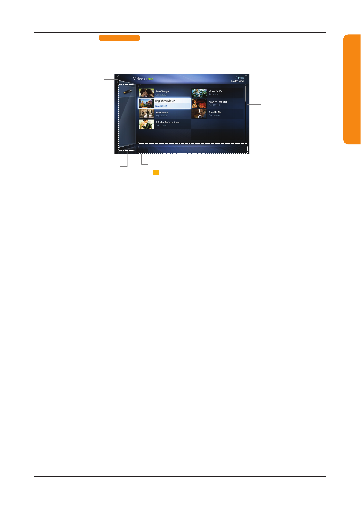
Information:
You can ascertain the
selected device name,
contents mode, folder/
file name, page and
sorting list.
Contents mode / Device name:
You can select the desired
Contents mode or Device name.
When PC is connected, you can
select PC through PC Share
Manager.
Operation Buttons:
-
ACBD
Yellow (Edit Mode); Selects the desired music. The check box is
shown in the screen to check the music you want. It is only available in
Music.
- �
(Jump Page); Move to next or previous page.
- T Tools; Displays the option menu.
- R Return; Move to the previous step.
File List Section:
You can confirm the
files and groups that are
sorted by category.
T
Tools R Return
Screen Display
for LED 5000 series
Move to the desired file using the ◄/►/▲/▼ buttons and then press the ENTERE or (Play) button.
The file is played. My Contents screen may differ depending on the way to enter the screen.
For LED 4000(19" / 32")_5000(22" / 27") series
Page 24
2-18
2. Product specications
For LED 4000(19" / 32")_5000(22" / 27") series
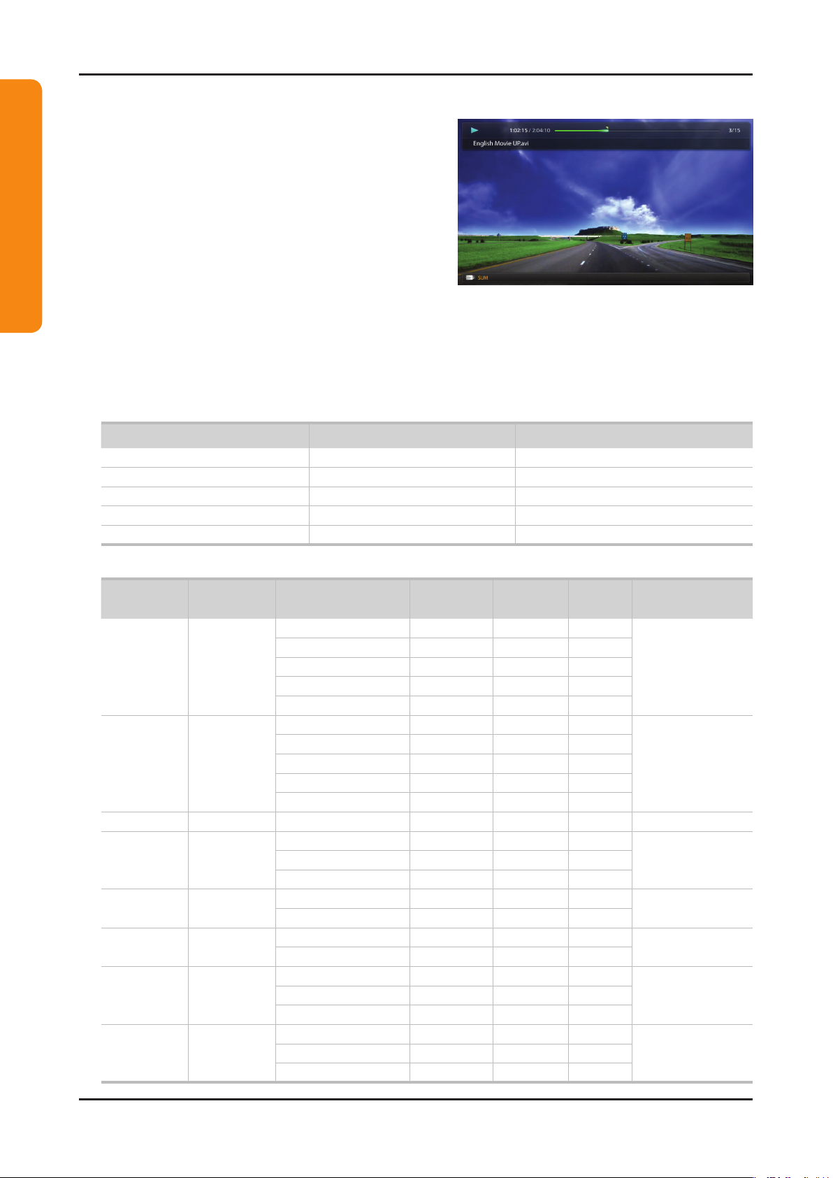
Videos ●
Playing Video01.
Press the 1. ◄/►/▲/▼ button to select the desired video in
the le list.
Press the 2. ENTERE button or (Play) button.
– The selected le name is displayed on the top with its
playing time.
– If video time information is unknown, play time and
progress bar are not displayed.
– During video playback, you can search using ◄ and ►
button.
– You can use (REW) and μ (FF) buttons during
playback.
N In this mode, you can enjoy movie clips contained on a Game, but you cannot play the Game itself.
● Supported Subtitle Formats
Name File extension Format
MPEG-4 time-based text .ttxt XML
SAMI .smi HTML
SubRip .srt string-based
SubViewer .sub string-based
Micro DVD .sub or .txt string-based
● Supported Video Formats
File
Extention
*.avi
*.mkv
*.asf ASF
*.wmv ASF Window Media Video v9 1920 x 1080 6 ~ 30 25 WMA
*.mp4 MP4
*.3gp 3GPP
*.vro
*.mpg
*.mpeg
*.ts
*.tp
*.trp
Container Video Codec Resolution
Divx 3.11/4.x/5.1/6.0 1920 x 1080 6 ~ 30 8
AVI
MKV
VRO
VOB
PS
TS
XviD 1920 x 1080 6 ~ 30 8
H.264 BP/MP/HP 1920 x 1080 6 ~ 30 25
MPEG4 SP/ASP 1920 x 1080 6 ~ 30 8
Motion JPEG 640 x 480 6 ~ 30 8
Divx 3.11/4.x/5.1/6.0 1920 x 1080 6 ~ 30 8
XviD 1920 x 1080 6 ~ 30 8
H.264 BP/MP/HP 1920 x 1080 6 ~ 30 25
MPEG4 SP/ASP 1920 x 1080 6 ~ 30 8
Motion JPEG 640 x 480 6 ~ 30 8
H.264 BP/MP/HP 1920 x 1080 6 ~ 30 25
XVID 1920 x 1080 6 ~ 30 8
H.264 BP/MP/HP 1920 x 1080 6 ~ 30 25
MPEG4 SP/ASP 1920 x 1080 6 ~ 30 8
MPEG2 1920 x 1080 24/25/30 30
MPEG1 1920 x 1080 24/25/30 30
MPEG1 1920 x 1080 24/25/30 30
MPEG2 1920 x 1080 24/25/30 30
H.264 1920 x 1080 6 ~ 30 25
MPEG2 1920 x 1080 24/25/30 30
H.264 1920 x 1080 6 ~ 30 25
VC1 1920 x 1080 6 ~ 30 25
Frame rate
(fps)
Bit rate
(Mbps)
Audio Codec
MP3/AC3
/LPCM
/ADPCM
/DTS Core
MP3/AC3
/LPCM
/ADPCM
/WMA
MP3/ADPCM /AACMPEG4 SP/ASP 1920 x 1080 6 ~ 30 8
ADPCM/AAC
/HE-AAC
AC3/MPEG
/LPCM
AC3/MPEG
/LPCM/AAC
AC3/AAC
/MP3/DD+
/HE-AAC
Page 25

2-19
2. Product specications
Other Restrictions02.
N NOTE
If there are problems with the contents of a codec, the codec will not be supported.•
If the information for a Container is incorrect and the le is in error, the Container will not be able to play correctly.•
Sound or video may not work if the contents have a standard bit rate/frame rate above the compatible Frame/sec listed in the •
table above.
If the Index Table is in error, the Seek (Jump) function is not supported.•
When playing the video through network, it may not work depending on the network status. •
The videos over 10Mbps(bit rate) may be interrupted.•
Video Decoder Audio Decoder
Supports up to H.264, Level 4.1•
H.264 FMO / ASO / RS, VC1 SP / MP / AP L4 and •
AVCHD are not supported.
XVID, MPEG4 SP, ASP: •
– Below 1280 x 720: 60 frame max
– Above 1280 x 720: 30 frame max
GMC is not support.•
for LED 5000 series
Supports up to WMA 7, 8, 9, STD, 9 PRO•
WMA Lossless, Voice Lossless, Voice is not supported.•
WMA sampling rate 22050Hz mono is not supported.•
For LED 4000(19" / 32")_5000(22" / 27") series
Page 26

2-20
2. Product specications
For LED 4000(19" / 32")_5000(22" / 27") series
Music ●
Playing Music01.
Press the 1. ◄/►/▲/▼ button to select the desired Music in
the le list.
Press the 2. ENTERE button or (Play) button.
– You can use (REW) and μ (FF) buttons during
playback.
N Only displays the les with MP3 and PCM le extension. Other le extensions are not displayed, even if they are
saved on the same USB device.
N If the sound is abnormal when playing MP3 les, adjust the Equalizer in the Sound menu. (An over-modulated
MP3 le may cause a sound problem.)
Playing selected music02.
Press the 1.
Select the desired music.2.
– The check box appears to the left of the selected les.
Press the 3. TOOLS button and select Play Selected Contents.
– You can select or deselect all music pressing the Select All/Deselect All.
(Edit Mode) button.
C
Page 27

2-21
2. Product specications
Photos ●
Viewing a Photo (or Slide Show)01.
Press the 1. ◄/►/▲/▼ button to select the desired Music in
the le list.
Press the 2. ENTERE button or (Play) button.
– When a selected photo is displayed, press the
ENTERE button to start the slide show.
– During the slide show, all les in the le list will be
displayed in order.
N When you press the (Play) button in the le list, slide show will be started immediately.
N Music les can be automatically played during the Slide Show if the Background Music is set to On.
N The BGM Mode cannot be changed until the BGM has nished loading.
For LED 4000(19" / 32")_5000(22" / 27") series
Page 28
2-22
2. Product specications
For LED 4000(19" / 32")_5000(22" / 27") series
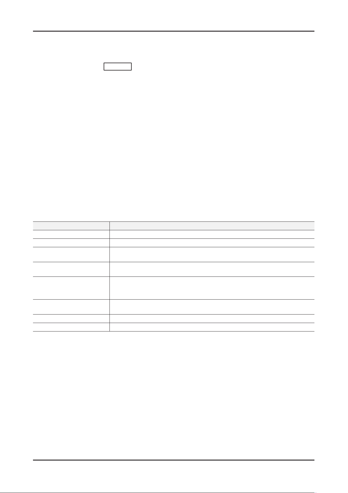
My Contents - Additional Functions
Videos/Music/Photos Play Option menu01.
During playing a le, press the TOOLS button.
Category Operation Videos Music Photos
Title You can move the other le directly.
Time Search
Shufe Mode You can play the music randomly.
Repeat Mode You can play movie and music les repeatedly.
Picture Size You can adjust the picture size to your preference.
Picture Mode You can adjust the picture setting.
SRS TheaterSound You can adjust the sound setting.
Subtitle Language
Subtitle Setting
Start Slide Show/Pause Slide Show You can start or pause a Slide Show.
Slide Show Speed You can select the slide show speed during the slide show.
Background Music You can on/off background music when watching a Slide Show.
Background Music Setting You can select background music when watching a Slide Show.
Zoom You can zoom into images in full screen mode.
Rotate You can rotate images in full screen mode.
Information You can see detailed information about the played le.
You can search the video using l and r button at one minute interval
or entering the number directly.
You can enjoy video in one of supported languages as required. The
function is only enabled when stream-type les which support multiple
audio formats are played.
You can play the video with Subtitles. This function only works if the
subtitles are the same le name as the video.
c
c
c
c c
c
c c
c c c
c
c
c
c
c
c
c
c
c c c
Page 29
2-23
2. Product specications
2-4-2. Media Contents
for LED 5500 series
Using the Media Contents
Enjoy photos, music and/or movie files saved on a USB Mass Storage Class (MSC) device.
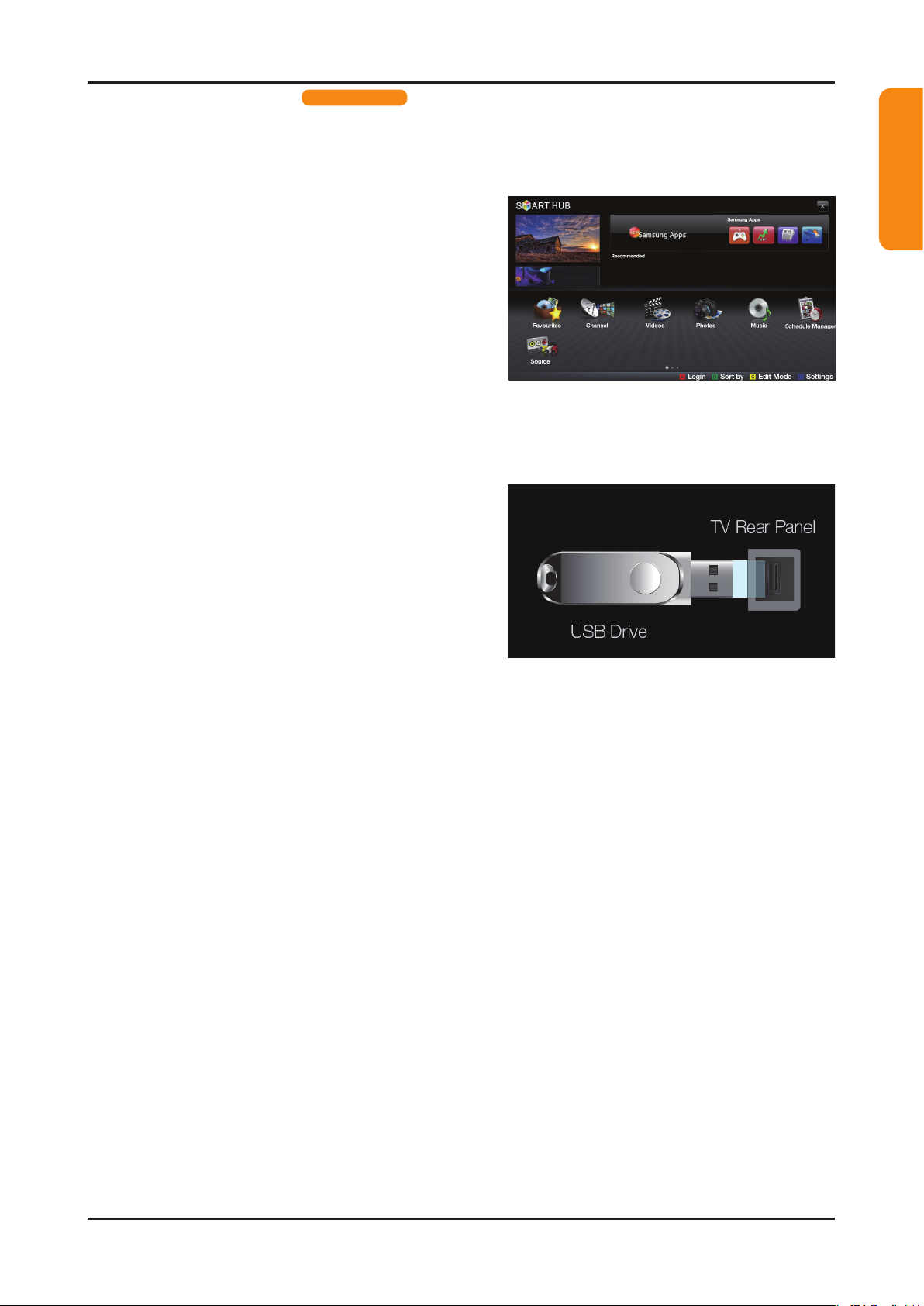
Press the 1. SMART HUB button.
Press 2. u/d button to select desired menu (Videos,
Photos, Music), then press the ENTERE button.
* The displayed menu may differ depending on the model.
Connecting a USB Device
Turn on your TV.1.
Connect a USB device containing photo, music and/or 2.
movie les to the USB jack on the side of the TV.
When USB is connected to the TV, popup window 3.
appears. Then you can select Connected Device.
For LED 5500 series
* It may differ depending on the model.
N Need-to-Know List before using My Contents.
If an external USB device connected to the TV’s USB port draws an excessive amount of current from the •
port, the message “USB Power overload” appears on the screen. This is not a problem with the TV, which
provides the standard current from its USB ports, but a problem with the external device. Please contact the
manufacturer of the device for support.
Page 30

2-24
2. Product specications
For LED 5500 series
Connecting to the PC through network
You can play pictures, music and videos saved on your PC through a network connection in the SMART HUB mode.
Before using My Contents functions...01.
N It might not work properly with unlicenced multimedia les.
N Need-to-Know List before using Media Contents.
For more information on how to congure your network, refer to ‘Setting the Network”.1.
You are recommended to locate both TV and PC in same subnet. The rst 3 parts of the subnet address of the TV and the PC IP addresses should be the same and only the last part (the host address) should be
changed. (e.g. IP Address: 123.456.789.**)
Using a LAN cable, connect between the external modem and the PC onto which the Samsung PC Share 2.
Manager programme will be installed.
You can connect the TV to the PC directly without connecting it through a Sharer (Router). -
N Functions that are not supported when connecting to a PC through a network:
The • BGM Mode and Background Music Setting functions.
Sorting les by preference in the • Photos, Music and Videos folders.
The • (REW) or μ (FF) button while a movie is playing.
N The Divx DRM, Multi-audio, embedded caption does not supported.
N Samsung PC Share manager should be permitted by the firewall programme on your PC.
N When you use SMART HUB mode through a network connection, depending on the functions of the
provided server:
The sorting method may vary.•
The • Scene Search function may not be supported.
The • Resume, which resumes playing of a video, may not be supported.
The - Resume function does not support multiple users. (It will have only memorized the point where the
most recent user stopped playing.)
The • l or r buttons may not work depending on the content information.
N You may experience file stuttering while playing a video in SMART HUB through a network connection.
MTP (Media Transfer Protocol) is not supported.•
The le system supports FAT16, FAT32 and NTFS.•
Certain types of USB Digital camera and audio devices may not be compatible with this TV.•
Media Contents• only supports USB Mass Storage Class (MSC) devices. MSC is a Mass Storage Class Bulk-
Only Transport device. Examples of MSC are Thumb drives, Flash Card Readers and USB HDD (USB HUB are
not supported). Devices should be connected directly to the TV’s USB port.
Before connecting your device to the TV, please back up your les to prevent them from damage or loss of data. •
SAMSUNG is not responsible for any data le damage or data loss.
Connect a USB HDD to the dedicated USB 1 (HDD) port.•
Do not disconnect the USB device while it is loading.•
The higher the resolution of the image, the longer it takes to display on the screen.•
The maximum supported JPEG resolution is 15360X8640 pixels.•
For unsupported or corrupted les, the “Not Supported File Format” message is displayed.•
If the les are sorted by • Folder View, up to 1000 les can be displayed in each folder.
MP3 les with DRM that have been downloaded from a non-free site cannot be played. Digital Rights •
Management (DRM) is a technology that supports If more than two MSC devices are connected, some of them
may not be recognized. A USB device that requires high power (more than 500mA or 5V) may not be supported.
If an over-power warning message is displayed while you are connecting or using a USB device, the device •
may not be recognized or may malfunction.
If the TV has been no input during time set in • Auto Protection Time, the Screensaver will run.
The power-saving mode of some external hard disk drives may be released automatically when connected to the TV.
•
If a USB extension cable is used, the USB device may not be recognized or the les on the device may not be read•
If a USB device connected to the TV is not recognized, the list of les on the device is corrupted or a le in the •
list is not played, connect the USB device to the PC, format the device and check the connection.
If a le deleted from the PC is still found when • SMART HUB is run, use the “Empty the Recycle Bin” function on
the PC to permanently delete the le. Before using My Contents functions...
.
Page 31

2-25
2. Product specications
◀
E
or � (Play) button. The file is played.
Device name: Displays a
connected device name.
Change Content/Device:
Changes the content type or
connected device.
Sorting: Displays sorting
standard. Sorting standard
is different depending on the
contents.
Edit Mode: Select and play
multiple les or assign them
to My Playlist. This function is
available only for Music.
Home: Return to content
home
Page bar: Moves to another page containing a list of les.
File List Section: You
can conrm the les and
groups that is sorted by
each category.
I Love Music
Ming
Music_1
No Singer
Music_2
No Singer
Music_3
No Singer
Music_4
No Singer
Music_6
No Singer
Music_5
No Singer
Sweet Candy
Music_7
No Singer
Music_8
No Singer
Music_9
No Singer
SUM
Music
Upper Folder
Screen Display02.
Move to the file you desired using the up/down/right/left buttons and then press the ENTERE or (Play) button.
The file is played.
For LED 5500 series
Page 32

2-26
2. Product specications
For LED 5500 series
Videos ●
N In this mode, you can enjoy movie clips contained on a Game, but you cannot play the Game itself.
● Supported Subtitle Formats
Playing Video01.
Press the 1. ◄/►/▲/▼ button to select the desired le in the
le list.
Press the 2. ENTERE button or (Play) button.
– The selected le name is displayed on the top with its
playing time.
– If video time information is unknown, play time and
progress bar are not displayed.
– During video playback, you can search using ◄ and ►
button.
– You can use (REW) and μ (FF) buttons during
playback.
Name File extension Format
MPEG-4 time-based text .ttxt XML
SAMI .smi HTML
SubRip .srt string-based
SubViewer .sub string-based
Micro DVD .sub or .txt string-based
● Supported Video Formats
File
Extention
*.avi
*.mkv
*.asf ASF
*.wmv ASF Window Media Video v9 1920 x 1080 6 ~ 30 25 WMA
*.mp4 MP4
*.3gp 3GPP
*.vro
*.mpg
*.mpeg
*.ts
*.tp
*.trp
Container Video Codec Resolution
Divx 3.11/4.x/5.1/6.0 1920 x 1080 6 ~ 30 8
AVI
MKV
VRO
VOB
PS
TS
XviD 1920 x 1080 6 ~ 30 8
H.264 BP/MP/HP 1920 x 1080 6 ~ 30 25
MPEG4 SP/ASP 1920 x 1080 6 ~ 30 8
Motion JPEG 640 x 480 6 ~ 30 8
Divx 3.11/4.x/5.1/6.0 1920 x 1080 6 ~ 30 8
XviD 1920 x 1080 6 ~ 30 8
H.264 BP/MP/HP 1920 x 1080 6 ~ 30 25
MPEG4 SP/ASP 1920 x 1080 6 ~ 30 8
Motion JPEG 640 x 480 6 ~ 30 8
H.264 BP/MP/HP 1920 x 1080 6 ~ 30 25
XVID 1920 x 1080 6 ~ 30 8
H.264 BP/MP/HP 1920 x 1080 6 ~ 30 25
MPEG4 SP/ASP 1920 x 1080 6 ~ 30 8
MPEG2 1920 x 1080 24/25/30 30
MPEG1 1920 x 1080 24/25/30 30
MPEG1 1920 x 1080 24/25/30 30
MPEG2 1920 x 1080 24/25/30 30
H.264 1920 x 1080 6 ~ 30 25
MPEG2 1920 x 1080 24/25/30 30
H.264 1920 x 1080 6 ~ 30 25
VC1 1920 x 1080 6 ~ 30 25
Frame rate
(fps)
Bit rate
(Mbps)
Audio Codec
MP3/AC3
/LPCM
/ADPCM
/DTS Core
MP3/AC3
/LPCM
/ADPCM
/WMA
MP3/ADPCM /AACMPEG4 SP/ASP 1920 x 1080 6 ~ 30 8
ADPCM/AAC
/HE-AAC
AC3/MPEG
/LPCM
AC3/MPEG
/LPCM/AAC
AC3/AAC
/MP3/DD+
/HE-AAC
Page 33

2-27
2. Product specications
Other Restrictions02.
N NOTE
If there are problems with the contents of a codec, the codec will not be supported.•
If the information for a Container is incorrect and the le is in error, the Container will not be able to play correctly.•
Sound or video may not work if the contents have a standard bit rate/frame rate above the compatible Frame/sec listed in •
the table above.
If the Index Table is in error, the Seek (Jump) function is not supported.•
You may experience le stuttering while playing a video through a network connection.•
Video Decoder Audio Decoder
Supports up to H.264, Level 4.1•
H.264 FMO / ASO / RS, VC1 SP / MP / AP L4 and •
AVCHD are not supported.
XVID, MPEG4 SP, ASP: •
– Below 1280 x 720: 60 frame max
– Above 1280 x 720: 30 frame max
GMC is not support.•
Supports up to WMA 7, 8, 9, STD, 9 PRO•
WMA Lossless, Voice Lossless, Voice is not supported.•
WMA sampling rate 22050Hz mono is not supported.•
Playing movie le continuously (Resume Play)03.
If you exit the playing Videos function, it can be played later from the point where it was stopped.
N The Resume function does not support multiple users. (It will have only memorised the point where the most
recent user stopped playing.)
Select the movie le you want to play continuously by pressing the 1. l or r button to select it from the le list
section.
Press the 2. (Play) / ENTERE button.
– A triangle icon will appear on the progress bar when the playback starts.
Press the 3. TOOLS button, and then select Resume. The Movie will begin to play from where it was stopped.
For LED 5500 series
Using the 04. Scene Search function
If you want to use the Scene Search function during playback, you can explore scene divided in to 5 chapters you
want.
N If the index information is damaged or unsupported, you will not be able to use the Scene Search function.
Select the movie le you want to play from the le list 1.
section.
Press the 2. (Play) / ENTERE button.
Press the 3. TOOLS button, and then press the l or r button
to select Scene Search. A pop up window appears.
Press the 4. l or r button to select a scene you want search.
The playback will start from the selected scene.
Page 34

2-28
2. Product specications
For LED 5500 series
Music ●
Playing Music01.
Press the 1. ◄/►/▲/▼ button to select the desired music
le in the le list.
Press the 2. ENTERE button or (Play) button.
– During playing the music, you can search using the
(FF) and μ (REW) buttons.
N Only displays the les with MP3 and PCM le extension. Other le extensions are not displayed, even if
they are saved on the same USB device.
N If the sound is abnormal when playing MP3 les, adjust the Equalizer in the Sound menu. (An over-
modulated MP3 le may cause a sound problem.)
Creating My Playlist02.
On the 1. Music screen in the SMART HUB menu, press the l / r / u / d button to select Edit Mode, and then
press the ENTERE button.
Press the 2. l / r / u / d button to select the tracks you want to add and press the ENTERE button.
– The check box appears to the left of the selected les.
– To select all the les in the current page, select Select All at the top.
Press the 3. l / r / u / d button to select Add to My Playlist.
– Note that selecting My Playlist Initialize will return My Playlist to the default playlist.
Press the 4. ENTERE button. The message “Selected items added to My Playlist” is displayed.
The newly created or updated playlist will be in the main 5. Music page.
Playing 03. My Playlist
Select the My Playlist folder and it will play automatically. Press the u or d button to select a different music le
within the play list.
N To delete a le from My Playlist, select the recycle bin icon next to the le you want to delete by using the
direction buttons.
Playing the selected music les04.
On the 1. Music screen in the SMART HUB menu, press the l / r / u / d button to select Edit Mode, and then
press the ENTERE button.
Press the 2. l / r / u / d button to select the desired music le in the le list, and then ENTERE button.
– The check box mark appears to the left of the selected les.
– To select all the les in the current page, select Select All at the top.
– To cancel a selection, press the ENTERE button again.
Press the 3. l / r / u / d button to select Play. The selected music les will be play.
Page 35

2-29
2. Product specications
Photos ●
Viewing a Photo (or 01. Slide Show)
Press the 1. ◄/►/▲/▼ button to select the desired le in the
le list.
Press the 2. ENTERE button.
– When you press the (Play) button in the le list,
slide show will be started immediately.
– All les in the le list section will be displayed in the
slide show.
– During the slide show, les are displayed in order from
currently being shown.
N Music les can be automatically played during the slide show if the Background Music is set to On.
N The BGM Mode cannot be changed until the BGM has nished loading.
For LED 5500 series
Page 36

2-30
2. Product specications
For LED 5500 series
Media Contents - Additional Functions
Sorting the le list01.
To sort les in the le list, select the Sorting by using the l / r / u / d button.
And then press the ENTERE button.
Folder View
Title
Latest Date Sorts and shows les by the latest date.
Earliest Date Sorts and shows les by the earliest date.
Artist Sorts the music le by artist in alphabetical order.
Album Sorts the music le by album in alphabetical order.
Genre Sorts music les by the genre.
Monthly Sorts and shows photo les by month.
Category Operation Videos Music Photos
Displays the whole folder. You can view the le name and thumbnail by
selecting the folder.
Sorts and displays the le title in Symbol/Number/Alphabet/Special
order.
c c c
c c c
c c
c c
c
c
c
c
Page 37

2-31
2. Product specications
2-4-3. e-Manual
How to view the e-Manual
Page 38

2-32
2. Product specications
Page 39

2-33
2. Product specications
2-4-4. AllShare
Advanced Features
AllShare
¦ About AllShare
AllShare connects your TV, mobile phones and other
devices which are compatible through a network. On your
TV, you can view call arrivals, SMS messages and schedules
set on your mobile phones. In addition, you can play media
contents including videos, photos and music saved on your
mobile phones or the other devices (such as your PC) by
controlling them on the TV via the network. Additionally, you
can use your TV as a monitor for your mobile when browsing
a web page.
✎
For more information, visit “www.samsung.com” or
contact the Samsung call centre. Mobile devices may
need additional software installation. For details, refer to
each device's user’s guide.
¦ Setting Up AllShare
Setup
■ Message (On / Off): Enables or disables the message
function (for call arrivals, SMS messages and schedules
set on your mobile phones).
■ Media (On / Off): Enables or disables the media
function. When the media function is on, it plays videos,
photos and music from a mobile phone or other device
that supports AllShare.
■ ScreenShare (On / Off): Enables or disables the
ScreenShare function for using mobile phone as a
remote control.
■ TV name: Sets the TV name so you can nd it easily on
a mobile device.
✎
If you select User Input, you can type on the TV
using the OSK (On Screen Keyboard).
Message / Media / ScreenShare
Shows a list of mobile phones or connected devices which
have been set up with this TV for using the Message,
Media, or ScreenShare function.
✎
The Media function is available in all mobile devices
which support AllShare.
■ Allowed / Denied: Allows/Blocks the mobile phone.
■ Delete: Deletes the mobile phone from the list.
✎
This function only deletes the name of the mobile
from the list. If the deleted mobile device is turned
on or trys to connect to the TV, it may appear on
the list again.
Using the Message Function
Using this function, you view call arrivals, SMS messages
and schedules set on the mobile phone through the alarm
window while watching TV.
✎
NOTE
x
To disable the alarm window, set Message to Off in
Setup of AllShare.
x
If OK is selected, or if OK is not selected after the
message has appeared three times, the message
will be deleted. The message is not deleted from the
mobile phone.
x
The alarm window can be displayed while using
some applications such as Media Play etc. To view
the contents of a message, switch to TV viewing
mode.
x
When a message from an unknown mobile phone is
displayed, select the mobile phone on the message
menu in AllShare and select Denied to block the
phone.
Message View
If a new SMS message arrives while you are watching
TV, the alarm window appears. If you click the OK
button, the contents of the message are displayed.
✎
You can configure the viewing settings for SMS
messages on your mobile phones. For the
procedures, refer to the mobile phone manual.
✎
Some types of characters may be displayed as
blank or broken characters.
AllShare™
3/7
E
Select
R
Return
e
Exit
Setup
R
Return
Setup
Message
Media
ScreenShare
Message : On
Media : On
ScreenShare : On
TV name : Home TV
For LED 5000(Only 32", 37", 40", 46")_5500 series
Page 40

2-34
2. Product specications
04 Advanced Features
Call Arrival Alarm
If a call arrives while you are watching TV, the alarm
window appears.
Schedule Alarm
While you are watching TV, the alarm window appears to
display the registered event.
✎
You can configure viewing settings for schedule
contents on your mobile phones. For the
procedures, refer to the mobile phone manual.
✎
Some special characters may be displayed as
blank or broken characters.
Using the Media Function
An alarm window appears informing the user that the media
contents (videos, photos, music) sent from a mobile phone
will be displayed on your TV. The contents are played
automatically 3 seconds after the alarm window appears.
If you press the RETURN or EXIT button when the alarm
window appears, the media contents are not played.
✎
NOTE
x
If the media function executes for the first time,
the warning popup windows appears. Press the
ENTERE button to select Allow, then you can use
Media function on that device.
x
To turn off the media contents transmission from
the mobile phone, set Media to Off in the AllShare
setup.
x
Contents may not be played on your TV depending
on their resolution and format.
x
The ENTERE and ◄ / ► buttons may not work
depending on the type of media content.
x
Using the mobile device, you can control the media
playing. For details, refer to each mobile’s user’s
guide.
x
When you want to play media contents from
your PC, select the PC icon on the main display
of AllShare. Then the TV’s Media Play menu
automatically changes. For more detail information,
refer to “Media Play” (p. 29).
Using ScreenShare Function
Screenshare displays the same web page as provide in
mobile. Using ScreenShare, you can open the various
contents saved in a mobile phone. For example, the image
below displays an access page for contents from a mobile.
You can read the mobile’s various les and view the phone
book and calender on the TV. Also, in phone book, you can
make a call to other person, or can send to SMS.
✎
NOTE
x
In Samsung mobile, ScreenShare must be installed
and the supporting application must be executed;
then you can use the ScreenShare function.
x
Available buttons on your remote control may vary
for each page.
x
Doc Viewer can read files in doc format, but cannot
modify them.
x
The screen display may differ depending on the
connected device.
Using your Samsung phone to control your TV Simply
Before you can use this feature, you must connect to
a Samsung mobile phone that supports ScreenShare
functions. When operating the TV with your mobile phone,
only the POWER,
Y
, P</> and MUTE buttons are
supported.
✎
Even if you keep pressing down on a control button
(channel or volume) on the mobile phone, the value will
only go up or down by one unit.
E
Select Return
My Mobile
Contacts Calendar Doc Viewer
DenyAllow
“Unknown Device 0” is requesting that the media le be allowed to play.
If you wish to allow the media le to be played at your device, please press
“Allow”, otherwise press “Deny”.
You can also change the setting (or resetting) of this feature at “AllShare
Setup”.
Warning: Please note that if your device is connected to unsecured or
unfamiliar network, unwanted or inappropriate contents might be played.
If you are not sure about the network's identity or content’s appropriateness,
we strongly recommend that you do not “Allow” the request to play.
For LED 5000(Only 32", 37", 40", 46")_5500 series
Page 41

2-35
2. Product specications
Installed Applications
list: Displays the installed
applications in the TV.
Recommended Applications:
Displays the recommended
service by Samsung. You are
not able to add ordelete a
service in this list.
Controls:
● a Red (Login): To log in to Smart Hub.
● b Green (Sort by): To sort the applications by category.
● { Yellow (Edit Mode): You can edit the applications (such as
move, making folder).
● } Blue (Settings): Edit and congure applications and Smart
Hub settings.
N The colour buttons may work differently depending on the
application.
Application service: You can
experience various service by
provided samsung.
Recommended
Favourites
Samsung Apps
Channel
Source
Videos Schedule ManagerPhotos Music
a
Login b Sort by { Edit Mode } Settings
TV Screen: Displays the
current channel.
Information: Displays
notices, new applications,
and advertisements
brought to you by
Samsung product
introductions.
2-4-5. Smart Hub
for LED 5500 series
Using the Media Contents
Enjoy photos, music and/or movie files saved on a USB Mass
Storage Class (MSC) device.
Screen Display01.
For LED 5500 series
* The displayed menu may differ depending on the model.
N NOTE
Congure the network settings before using Smart Hub. For more information, refer to “Network Settings”.•
Unsupported fonts within the provider’s content will not display normally.•
Slow responses and/or interruptions may occur, depending on your network conditions.•
Depending on the region, English may be the only language supported for application services.•
This feature is not available in some locations.•
If you experience a problem using a application, please contact the content provider.•
According to circumstances of the contents provider, an application’s updates or t he application itself may be •
discontinued.
Depending on your country’s regulations, some applications may have limited service or not be supported.•
Page 42

2-36
2. Product specications
For LED 5500 series
For an application with multiple accounts, select to access the different accounts.
N For a more enjoyable application experience, register and log in to your account.
N For instructions on creating an account, refer to “How to create an Smart Hub ID”.
Before creating a Smart Hub ID, you should download the application first on the Samsung Apps.
N For a more enjoyable application experience, register and log in to your account.
N For instructions on creating an account, refer to “How to create an Smart Hub ID”.
Account Login02.
Press the Red button in the 1. Smart Hub home page.
Select ^ by pressing the 2. u / d / l / r button.
The account list appears.
If you want to create an account, select Create Account then •
the create account OSD window will appear.
Select the desired 3. Smart Hub ID, and the press the
ENTERE button.
After selecting 4. Smart Hub ID, enter the Password using
the remote control.
When login succeeds, • Smart Hub ID will be displayed on the
screen.
How to create a Smart Hub ID03.
Press the Red button. The Login screen appears.1.
Select 2. Create Account. The Create Account screen will appear.
Press the 3. ENTERE button to enter a new Smart Hub ID. The Keypad screed will appear.
Using the keypad screen, enter a 4. Smart Hub ID.
A • Smart Hub ID must be created in “sample@sample.com” form.
Using the Keypad
Pressing the – button on the remote while you are using the Screen Keypad enables you to change the text fields
to lower case, capitalized case, upper case, numbers and icons.
You can use this Screen Keypad in a several Smart Hub applications.
Here is how to input characters using keypad of ABC type.
4-1. For example, suppose that you want to input “105Chang”.
4-2. Press the – button on the remote 3 times to change the input mode from lower case to numbers.
4-3. Press the 1, 0 and 5 button in numerical order.
4-4. Press the – button on the remote 4 times to change the input mode from numbers to upper case.
4-5. Press the 2 button on the remote 3 times to input C.
4-6. Press the – button on the remote 3 times to change the input mode from upper case to lower case.
4-7. Press buttons on the remote to input the rest of “Chang”. When done, press the ENTERE button.
Using the remote control, enter the 5. Password.
Password must be 6~12 words.•
You can delete the entered character using the • PRE-CH button.
Using the • (REW) or μ (FF) button, you can select icon you want to enter in icon keypad screen.
Account created. You can use the services provided by all users of your Samsung TV with a single login by 6.
linking the users’ account to the TV ID. If you want to register a service site ID, select Yes. Service Site list will
appear on the screen.
Select Register of the Service Site you want, then press the 7. ENTERE button.
Using number buttons, enter your application site ID and password. Then press the 8. ENTERE button.
Registered successfully. If you add another service site, select Yes. then press the 9.
When completed, select OK. Then press the 10. ENTERE button.
ENTERE
button, go to step 5.
Page 43

2-37
2. Product specications
Setting up Smart Hub
Settings01.
Configure Smart Hub settings from this screen. Highlight
Settings using the u and d buttons and press the ENTERE
button.
Account Management•
Service Account: Register login information for service sites.
Change Password: Change account password.
Delete From List: Delete an account from the list of accounts.
Withdrawal: Withdraw membership from Smart Hub.
Service Manager•
Ticker Autorun (Off / On): You can set Ticker Autorun to come on when powering on the TV.
The - Ticker application provides useful News, Weather, and Stock Market information. The Ticker application on Smart Hub
must be downloaded to use this feature.
Depending on your country, Ticker application may have a different service or not be supported. -
Channel Bound Service (Off / On): Some channels support applications as an Internet data service, allowing you to access
the Internet service while watching TV.
Only available if supported by the broadcaster. -
Push Notication (Off/On): Allows to view or send a message as using a PC when using the Social TV menu (such as Twiter,
Facebook.)
Reset•
Resets Smart Hub settings to factory default settings. If you want reset Smart Hub, Enter password.
The default password set is “0-0-0-0.” -
If you forget the password you created, press the following sequence of remote control buttons to reset the password to “0-0- 0-0”: POWER (off) → MUTE → 8 → 2 → 4 → POWER (on).
Properties•
Detail: Display information about Smart Hub.
Check the speed of your internet connection: Test the speed of connection to the Samsung’s server. Each application can be
delayed depending on service provider.
Terms of Service Agreement: Display the Terms of Service Agreement.
For LED 5500 series
Page 44

2. Product specications
For LED 5500 series
Using the Smart Hub service
Samsung Apps is a store for downloading applications to be
used on Samsung TV/AV equipment.
Users can enjoy a variety of contents such as videos, music,
photos, games, useful information etc. using the downloaded
applications.
Additional applications will be available in the future.
• Red (Login)
A
To log in to the internet service.
• Green (List View / Thumbnail View)
B
To change the view mode.
• Blue (Sort by)
D
To sort the applications by Recommended, Most downloaded, Most recent or Name.
• R Return
Moves to previous menu.
The following categories are available:
Samsung Apps01.
Using the Samsung Apps by category02.
What’s New?: •
Video: • Displays various video media such as movies, TV shows and short length videos.
Game: • Displays various games such as sudoku and chess.
Sports: • Displays various sports media such as match information, images and short length video.
Lifestyle: • Includes various lifestyle media services such as music, personal photo management tools and social networking
such as Facebook and Twitter.
Information: • Includes various information services such as news, stocks and weather.
Other: • Includes other miscellaneous services.
My Account: • Displays the application list and your cyber cash balance.
Starting in the middle of 2010 (US and Korea only), you can purchase cybercash for buying applications through tv.samsung.com. -
Help: • If you have questions about Smart Hub, check this section rst.
[Legal Statement]
Due to the various capabilities of products featuring the Samsung Smart Hub - Content Service, as well as
limitations in the available content, certain features, applications, and services may not be available on all devices
or in all territories.
Some features on Smart Hub may also require additional peripheral devices or membership fees that are sold
separately. Please visit http://www.samsung. com for more information on specic device information and content
availability. The services and availability of content through Smart Hub are subject to change from time to time
without prior notice.
Displays newly registered applications.
2-38
Page 45

3. Disassembly and Reassembly
3. Disassembly and Reassembly
This section of the service manual describes the disassembly and reassembly procedures for the LED TV.
WARNING: This LED TV contains electrostatically sensitive devices. Use caution when handling these components.
3-1. Disassembly and Reassembly
Cautions: 1. Disconnect the LED TV from the power source before disassembly.
2. Follow these directions carefully; never use metal instruments to pry apart the cabinet.
UD5000_UD5500_UD5700(32", 37", 40", 46") / UD4000 (32")
Description Picture Description Screws
Place the TV face down on cushioned table.
1
Remove 4 screws from the Stand.(machine
type)
Remove Stand.
Remove the screws of Rear-Cover.
2
32" :• Remove the 11 screws.
(machine type : 2 EA)
37" :• Remove the 12 screws.
(machine type : 3 EA)
40" :• Remove the 16 screws.
(machine type : 4 EA)
46" :• Remove the 20 screws.
(machine type : 5 EA)
Lift up the Rear-Cover.
3
6001-002621
(Machine)
6003-001782
6001-002671
(Machine)
3-1
Page 46

3-2
3. Disassembly and Reassembly
Description Picture Description Screws
Remove the left and right speaker.
4
Remove the 6 screws of Main Board.
5
Remove the 5 screws of SMPS Board.
6001-002653
(Machine)
Remove the 6 screws of Bracket Stand Link &
6
Guide. (Machine type : 4 EA)
Remove the Stand Link.
7
6001-002653
(Machine)
6003-001782
Lift up the Panel.
8
Reassembly procedures are in the reverse order of disassembly procedures. ※
Page 47

3-3
3. Disassembly and Reassembly
Screw Size
Code No. A (mm) B (mm) C (mm)
6001-002621 8.0 ± 0.2 7.7 ± 0.3 3.83 ~ 3.98
6003-001782 8.2 ± 0.4 11.7 ± 0.3 3.81 ~ 3.91
6001-002671 7.3 ± 0.2 3.00 ± 0.02 5.7 ~ 6.0
6001-002653 7.3 ± 0.2 3.00 ± 0.02 5.7 ~ 6.0
Page 48

3-4
3. Disassembly and Reassembly
UD5000(22", 27") / UD4000(19")
Description Picture Description Screws
Place the TV face down on cushioned table.
1
Remove 4 screws from the Stand.
19", 22" : Remove 2 screws.•
27" : Remove 3 screws.•
Remove Stand.
6003-001782
Remove the screws of Rear-Cover.
2
32" :• Remove the 11 screws.
(machine type : 2 EA)
37" :• Remove the 12 screws.
(machine type : 3 EA)
40" :• Remove the 16 screws.
(machine type : 4 EA)
46" :• Remove the 20 screws.
(machine type : 5 EA)
Lift up the Rear-Cover.
3
Remove the left and right speaker.
4
6003-001782
Page 49

3-5
3. Disassembly and Reassembly
Description Picture Description Screws
Remove the 4 screws of Main Board.
5
Remove the 3 screws of SMPS Board.
Remove the Stand Link.
6
6003-000115
Lift up the Panel.
7
Reassembly procedures are in the reverse order of disassembly procedures. ※
Screw Size
Code No. A (mm) B (mm) C (mm)
6003-001782 8.2±0.4 11.7±0.3 3.81~3.91
6003-000115 6.3-0.5 5.6±0.4 2.85~2.95
Page 50

3. Disassembly and Reassembly
How to replace the function Board
Description Picture Description Refer
Remove the locking clip.
1
Heat the function Board and Remove
2
the function Board.
Place the new function Board.
3
FUNCTION Board
(BN96-16729*)
3-6
Locking the clip.
4
Bracket-Support, PCB
(BN61-07248A)
Page 51

4. Troubleshooting
4-1. Troubleshooting
4-1-1. Previous check
Check the various cable connections rst. 1.
• Check to see if any cables are damaged or burnt.
• Check to see if there is a disconnected or loose cable connection.
• Check to see if the cables are connected according to the connection diagram.
Check the power input to the Main Board.2.
X6 : UD55XX, 57XX(32", 37", 40", 46")
MAIN BOARD
4. Troubleshooting
SMPS BOARD
T-CON
X5 : UD50XX(32", 37", 40", 46")
UD40XX(32")
X5_Small : UD50XX(22", 27")
UD40XX(19")
MAIN BOARD
SMPS BOARD
T-CON
MAIN BOARDSMPS BOARD
4-1
Page 52

4-2
4. Troubleshooting
4-1-2. X6 : UD55XX, 57XX(32", 37", 40", 46")
No Power
The LEDs on the front panel do not work when connecting the power cord. -
Symptom
Major
checkpoints
The SMPS relay does not work when connecting the power cord. The units appears to be dead. -
The IP relay or the LEDs on the front panel does not work when connecting the power cord if the cables are
improperly connected or the Main Board or SMPS is not functioning. In this case, check the following:
Check the internal cable connection status inside the unit. Check the fuses of each part. Check the output voltage of SMPS. Replace the Main Board. -
Diagnostics
Lamp(Backlight) Off,
power indicator LED on?
Yes
Lamp(Backlight) Off,
power indicator LED on ?
Yes
Does proper Stand-By DC A5V
appear at VIA - A5V_PW ?
Yes
Does proper Main DC B13V, B5V
appear at VIA - B13V_PW, B5V_PW ?
Yes
Does proper DC A3.3V
appear at VIA - A3.3V_PW ?
Yes
No
No
No
No
No
Change the 14p power cable.
Change INVERTER/BALANCE B'D.
Change the Main Assy.
Does proper B3.3V, B1.5V appear at
VIA - B3.3V_PW, B1.5V_PW
Yes
Does proper DC B13V
appear at LVDS connector
Pin #1~5 of T-con b'd?
Yes
Does proper DC B13V
appear at F1 of T-con b'd?
Yes
A power is supplied to set?
Caution Make sure to disconnect the power before working on the IP board.
No
No
No
No
Change the LVDS cable.
Change the T-con b'd.
Check a other function.
(No picture part)
Replace a LCD Panel.
Page 53

4-3
4. Troubleshooting
Main Board_Bottom
TCON_Top
40" TCON
Pin #1~5
Page 54

4-4
4. Troubleshooting
No Video (Analog PC signal)
Symptom
Major
checkpoints
1
2
Audio is normal but no picture is displayed on the screen. -
Check the PC source Check the Arsenal, Check the Main Chipset. -
This may happen when the LVDS cable connecting the Main Board and the Panel is disconnected. -
Power indicator LED is off.
Lamp(Backlight) on, no video ?
Yes
Check the PC source and
check the connection of D-SUB ?
Yes
Does the signal appear at
PIN - R, G, B, HS, VS (R, G, B, H, V) ?
Yes
Does the digital data appear at
TP-E_TXCLK+, E_TXCLK- ,
O_TXCLK+, O_TXCLK- ?
No
No
No
No
Check a set in the 'Stand-by mode'
or 'DPMS mode'
Input the analog PC signal properly.
Check CN401, PC cable.
Change the Main Assy.
Check IC1001 (X6).
Change the Main Assy.
Diagnostics
Yes
Check the LVDS cable?
Check the T-Con B'd?
Replace the LCD panel?
No
Please, Contact Tech support.
Caution Make sure to disconnect the power before working on the IP board.
Page 55

4-5
4. Troubleshooting
Main Board_Top
Main Board_Bottom
Page 56

4-6
4. Troubleshooting
WAVEFORMS
1
2
PC input (V-sink , H-sink , R/G/B)
LVDS output
Page 57

4-7
4. Troubleshooting
No video (HDMI 1, 2, 3, 4 - Digital signal)
Symptom
Major
checkpoints
Audio is normal but no picture is displayed on the screen. -
Check the HDMI source. Check the HDMI switch, Check the Main Chipset. -
This may happen when the LVDS cable connecting the Main Board and the Panel is disconnected. -
Power indicator LED is off.
Lamp(Backlight) on, no video ?
Yes
Check the HDMI source and
check the connection of HDMI cable ?
Yes
Does the signal appear at
CN601 (Pin#12 , #7 )(HDMI1)
3
CN604 (Pin#12 , #7 )(HDMI2)
CN602 (Pin#12 , #7 )(HDMI3)
CN603 (Pin#12 , #7 )(HDMI4)
(HDMI RX_Clk , RX_Data) ?
Yes
No
No
No
Check a set in the 'Stand-by mode'.
Input the HDMI signal properly.
Check CN601, CN604
CN602, CN603.
Check HDMI cable.
Change the Main Assy.
Diagnostics
2
Does the digital data appear at
TP-E_TXCLK+, E_TXCLK- ,
O_TXCLK+, O_TXCLK- ?
Yes
Check the LVDS cable?
Check the T-Con B'd?
Replace the LCD panel?
No
No
Check IC1001 (X6).
Change the Main Assy.
Please, Contact Tech support.
Caution Make sure to disconnect the power before working on the IP board.
Page 58

4-8
4. Troubleshooting
Main Board_Top
Main Board_Bottom
Page 59

4-9
4. Troubleshooting
WAVEFORMS
3
2
HDMI input (RX_Data, RX_Clk)
LVDS output
Page 60

4-10
4. Troubleshooting
No Video (Tuner_CVBS)
Symptom
Major
checkpoints
2
Audio is normal but no picture is displayed on the screen. -
Check the Tuner CVBS source. Check the Tuner, Check the Main Chipset. -
This may happen when the LVDS cable connecting the Main Board and the Panel is disconnected. -
Power indicator LED is off.
Lamp(Backlight) on, no video ?
Yes
Check the RF source and
check the connection of RF cable ?
Yes
Does the DC TU5V_PW, TU33V_PW
appear at TP - TUNER_33V, B 5V
Pin of Tuner ?
Yes
Does the digital data appear at
TP-E_TXCLK+, E_TXCLK- ,
O_TXCLK+, O_TXCLK- ?
No
No
No
No
Check a set in the 'Stand-by mode'
Input the RF source properly.
Change the Main Assy.
Check IC1001 (X6).
Change the Main Assy.
Diagnostics
Yes
Check the LVDS cable?
Check the T-Con B'd?
Replace the LCD panel?
No
Please, Contact Tech support.
Caution Make sure to disconnect the power before working on the IP board.
Page 61

4-11
4. Troubleshooting
Main Board_Top
Main Board_Bottom
Page 62

4-12
4. Troubleshooting
WAVEFORMS
LVDS output
2
Page 63

4-13
4. Troubleshooting
No Video (Tuner DTV)
Symptom
Major
checkpoints
Audio is normal but no picture is displayed on the screen. -
Check the DTV source. Check the Tuner, Check the Main Chipset. -
This may happen when the LVDS cable connecting the Main Board and the Panel is disconnected. -
Power indicator LED is off.
Lamp(Backlight) on, no video ?
Yes
Check the RF source and
check the connection of RF cable ?
Yes
Check the 'signal strength' in Self Diagnosis
menu Strength is enough ?
Yes
Does the DC B5V_TU_PW, B33V_TU_PW
appear at #3, #5 Pin of Tuner ?
No
No
No
No
Check a set in the 'Stand-by mode'
Input the RF source properly.
Check the D-TV source.
Change the Main Assy.
Diagnostics
2
Yes
Does the digital data appear at
TP-E_TXCLK+, E_TXCLK- ,
O_TXCLK+, O_TXCLK- ?
Yes
Check the LVDS cable?
Check the T-Con B'd?
Replace the LCD panel?
No
No
Check IC1001 (X6).
Change the Main Assy.
Please, Contact Tech support.
Caution Make sure to disconnect the power before working on the IP board.
Page 64

4-14
4. Troubleshooting
Main Board_Top
Main Board_Bottom
Page 65

4-15
4. Troubleshooting
WAVEFORMS
2
LVDS output
Page 66

4-16
4. Troubleshooting
No Video (Video CVBS)
Symptom
Major
checkpoints
4
2
Audio is normal but no picture is displayed on the screen. -
Check the Video CVBS source -
Check the Main Chipset. -
This may happen when the LVDS cable connecting the Main Board and the Panel is disconnected. -
Power indicator LED is off.
Lamp(Backlight) on, no video ?
Yes
Check the video source and
check the connection of video cable?
Yes
Does the CVBS data appear at
PIN - COMP1_Y_CVBS ?
Yes
Does the digital data appear at
TP-E_TXCLK+, E_TXCLK- ,
O_TXCLK+, O_TXCLK- ?
No
No
No
No
Check a set in the 'Stand-by mode'.
Input the video source properly.
Check CN503.
Change the Main Assy.
Check IC1001 (X6).
Change the Main Assy.
Diagnostics
Yes
Check the LVDS cable?
Check the T-Con B'd?
Replace the LCD panel?
No
Please, Contact Tech support.
Caution Make sure to disconnect the power before working on the IP board.
Page 67

4-17
4. Troubleshooting
Main Board_Top
Main Board_Bottom
Page 68

4-18
4. Troubleshooting
WAVEFORMS
CVBS OUT (Grey Bar)
4
LVDS output
2
Page 69

4-19
4. Troubleshooting
No Video (Component)
Symptom
Major
checkpoints
5
2
Audio is normal but no picture is displayed on the screen. -
Check the Component source -
Check the Main Chipset. -
This may happen when the LVDS cable connecting the Main Board and the Panel is disconnected. -
Power indicator LED is off.
Lamp(Backlight) on, no video ?
Yes
Check the component source and
check the connection of component
cables(Y,Pb,Pr)?
Yes
Does the component data appear at
PIN - COMP1_Y_CVBS, COMP1_PB,
COMP1_PR ?
Yes
Does the digital data appear at
TP-E_TXCLK+, E_TXCLK- ,
O_TXCLK+, O_TXCLK- ?
No
No
No
No
Check a set in the 'Stand-by mode'
Input the component source properly.
Check CN503.
Change the Main Assy.
Check IC1001 (X6).
Change the Main Assy.
Diagnostics
Yes
Check the LVDS cable?
Check the T-Con B'd?
Replace the LCD panel?
No
Please, Contact Tech support.
Caution Make sure to disconnect the power before working on the IP board.
Page 70

4-20
4. Troubleshooting
Main Board_Top
Main Board_Bottom
Page 71

4-21
4. Troubleshooting
WAVEFORMS
5
2
Compnent_Y (Gray scale) / Pb / Pr (Color bar)
LVDS output
Page 72

4-22
4. Troubleshooting
No Sound
Symptom
Major
checkpoints
Video is normal but there is no sound.. -
When the speaker connectors are disconnected or damaged. When the sound processing part of the Main Board is not functioning. Speaker defect. -
Check the source and
check the connection of sound cable
(Comp/PC/DVI to HDMI) ?
Yes
Does the sound data appear at
PIN - COMP1_SR_IN,
COMP1_SL_IN
VIA - PC_DVI_SR_IN,
PC_DVI_SL_IN (PC/DVI) ?
Yes
Does the DC B12VS appear at
CN201 PIN 7,9 - B12VS_PW ?
Yes
No
No
No
Input the sound source properly.
Check CN503, CN402.
Change the Main Assy.
Change the Main Assy.
Diagnostics
7
Does the sound data appear at
TP - SPK_ L-, SPK_L+, SPK_R-, SPK_R+ ?
Yes
Replace speaker ?
TBD
No
No
Check IC1001 (X6).
Change the Main Assy.
Please, Contact Tech support.
Caution Make sure to disconnect the power before working on the IP board.
Page 73

4-23
4. Troubleshooting
Main Board_Top
Main Board_Bottom
Page 74

4-24
4. Troubleshooting
WAVEFORMS
Speaker out
7
Page 75

4-25
4. Troubleshooting
4-1-3. X5 : UD50XX(32", 37", 40", 46")_UD40XX(32")
No Power
The LEDs on the front panel do not work when connecting the power cord. -
Symptom
Major
checkpoints
The SMPS relay does not work when connecting the power cord. The units appears to be dead. -
The IP relay or the LEDs on the front panel does not work when connecting the power cord if the cables are
improperly connected or the Main Board or SMPS is not functioning. In this case, check the following:
Check the internal cable connection status inside the unit. Check the fuses of each part. Check the output voltage of SMPS. Replace the Main Board. -
Diagnostics
Lamp(Backlight) Off,
power indicator LED on?
Yes
Lamp(Backlight) Off,
power indicator LED on ?
Yes
Does proper Stand-By DC A5V
appear at VIA - A5V_PW ?
Yes
Does proper Main DC B13V, B5V
appear at
VIA - B13V_PW, B5V_PW ?
Yes
Does proper DC A3.3V
appear at VIA - A3.3V_PW ?
Yes
No
No
No
No
No
Change the 14p power cable.
Change INVERTER/BALANCE B'D.
Change the Main Assy.
Does proper B3.3V, B1.5V appear at
VIA - B3.3V_PW, B1.5V_PW ?
Yes
Does proper DC B13V
appear at LVDS connector
Pin #1~5 of T-con b'd?
Yes
Does proper DC B13V
appear at F1 of T-con b'd?
Yes
A power is supplied to set?
Caution Make sure to disconnect the power before working on the IP board.
No
No
No
No
Change the LVDS cable.
Change the T-con b'd.
Check a other function.
(No picture part)
Replace a LCD Panel.
Page 76

4-26
4. Troubleshooting
Main Board_Bottom
TCON_Top
40" TCON
Pin #1~5
Page 77

4-27
4. Troubleshooting
No Video (Analog PC signal)
Symptom
Major
checkpoints
1
2
Audio is normal but no picture is displayed on the screen. -
Check the PC source Check the Arsenal, Check the Main Chipset. -
This may happen when the LVDS cable connecting the Main Board and the Panel is disconnected. -
Power indicator LED is off.
Lamp(Backlight) on, no video ?
Yes
Check the PC source and
check the connection of D-SUB ?
Yes
Does the signal appear at
PIN - R, G, B, HS, VS (R, G, B, H, V) ?
Yes
Does the digital data appear at
TP-E_TXCLK+, E_TXCLK- ,
O_TXCLK+, O_TXCLK- ?
No
No
No
No
Check a set in the 'Stand-by mode'
or 'DPMS mode'
Input the analog PC signal properly.
Check CN401, PC cable.
Change the Main Assy.
Check IC1111 (X5).
Change the Main Assy.
Diagnostics
Yes
Check the LVDS cable?
Check the T-Con B'd?
Replace the LCD panel?
No
Please, Contact Tech support.
Caution Make sure to disconnect the power before working on the IP board.
Page 78

4-28
4. Troubleshooting
Main Board_Top
Main Board_Bottom
Page 79

4-29
4. Troubleshooting
WAVEFORMS
1
2
PC input (V-sink , H-sink , R/G/B)
LVDS output
Page 80

4-30
4. Troubleshooting
No video (HDMI 1, 2, 3, 4 - Digital signal)
Symptom
Major
checkpoints
Audio is normal but no picture is displayed on the screen. -
Check the HDMI source. Check the HDMI switch, Check the Main Chipset. -
This may happen when the LVDS cable connecting the Main Board and the Panel is disconnected. -
Power indicator LED is off.
Lamp(Backlight) on, no video ?
Yes
Check the HDMI source and
check the connection of HDMI cable ?
Yes
Does the signal appear at
CN601 (Pin#12 , #7 )(HDMI1)
3
CN604 (Pin#12 , #7 )(HDMI2)
CN602 (Pin#12 , #7 )(HDMI3)
CN603 (Pin#12 , #7 )(HDMI4)
(HDMI RX_Clk , RX_Data) ?
Yes
No
No
No
Check a set in the 'Stand-by mode'.
Input the HDMI signal properly.
Check CN601, CN604
CN602, CN605.
Check HDMI cable.
Change the Main Assy.
Diagnostics
2
Does the digital data appear at
TP-E_TXCLK+, E_TXCLK- ,
O_TXCLK+, O_TXCLK- ?
Yes
Check the LVDS cable?
Check the T-Con B'd?
Replace the LCD panel?
No
No
Check IC1111 (X5).
Change the Main Assy.
Please, Contact Tech support.
Caution Make sure to disconnect the power before working on the IP board.
Page 81

4-31
4. Troubleshooting
Main Board_Top
Main Board_Bottom
Page 82

4-32
4. Troubleshooting
WAVEFORMS
3
2
HDMI input (RX_Data, RX_Clk)
LVDS output
Page 83

4-33
4. Troubleshooting
No Video (Tuner_CVBS)
Symptom
Major
checkpoints
Audio is normal but no picture is displayed on the screen. -
Check the Tuner CVBS source. Check the Tuner, Check the Main Chipset. -
This may happen when the LVDS cable connecting the Main Board and the Panel is disconnected. -
Power indicator LED is off.
Lamp(Backlight) on, no video ?
Yes
Check the RF source and
check the connection of RF cable ?
Yes
Does the DC TU5V_PW, TU33V_PW
appear at TP - TUNER_33V, B 5V
Pin of Tuner ?
Yes
Does the DC B5V_TU_PW, B33V_TU_PW
2
appear at #3, #5 Pin of Tuner ?
No
No
No
No
Check a set in the 'Stand-by mode'
Input the RF source properly.
Change the Main Assy.
Check IC1111 (X5).
Change the Main Assy.
Diagnostics
Yes
Check the LVDS cable?
Check the T-Con B'd?
Replace the LCD panel?
No
Please, Contact Tech support.
Caution Make sure to disconnect the power before working on the IP board.
Page 84

4-34
4. Troubleshooting
Main Board_Top
Main Board_Bottom
Page 85

4-35
4. Troubleshooting
WAVEFORMS
LVDS output
2
Page 86

4-36
4. Troubleshooting
No Video (Tuner DTV)
Symptom
Major
checkpoints
Audio is normal but no picture is displayed on the screen. -
Check the DTV source. Check the Tuner, Check the Main Chipset. -
This may happen when the LVDS cable connecting the Main Board and the Panel is disconnected. -
Power indicator LED is off.
Lamp(Backlight) on, no video ?
Yes
Check the RF source and
check the connection of RF cable ?
Yes
Check the 'signal strength' in Self Diagnosis
menu Strength is enough ?
Yes
Does the DC B5V_TU_PW, B33V_TU_PW
appear at #3, #5 Pin of Tuner ?
No
No
No
No
Check a set in the 'Stand-by mode'
Input the RF source properly.
Check the D-TV source.
Change the Main Assy.
Diagnostics
2
Yes
Does the digital data appear at
TP-E_TXCLK+, E_TXCLK- ,
O_TXCLK+, O_TXCLK- ?
Yes
Check the LVDS cable?
Check the T-Con B'd?
Replace the LCD panel?
No
No
Check IC1111 (X5).
Change the Main Assy.
Please, Contact Tech support.
Caution Make sure to disconnect the power before working on the IP board.
Page 87

4-37
4. Troubleshooting
Main Board_Top
Main Board_Bottom
Page 88

4-38
4. Troubleshooting
WAVEFORMS
2
LVDS output
Page 89

4-39
4. Troubleshooting
No Video (Video CVBS)
Symptom
Major
checkpoints
Audio is normal but no picture is displayed on the screen. -
Check the Video CVBS source -
Check the Main Chipset. -
This may happen when the LVDS cable connecting the Main Board and the Panel is disconnected. -
Power indicator LED is off.
Lamp(Backlight) on, no video ?
Yes
Check the video source and
check the connection of video cable?
Yes
4
2
Does the CVBS data appear at
PIN - COMP1_Y_CVBS, COMP2_Y_CVBS ?
Yes
Does the digital data appear at
TP-E_TXCLK+, E_TXCLK- ,
O_TXCLK+, O_TXCLK- ?
No
No
No
No
Check a set in the 'Stand-by mode'.
Input the video source properly.
Check CN503.
Change the Main Assy.
Check IC1111 (X5).
Change the Main Assy.
Diagnostics
Yes
Check the LVDS cable?
Check the T-Con B'd?
Replace the LCD panel?
No
Please, Contact Tech support.
Caution Make sure to disconnect the power before working on the IP board.
Page 90

4-40
4. Troubleshooting
Main Board_Top
Main Board_Bottom
Page 91

4-41
4. Troubleshooting
WAVEFORMS
CVBS OUT (Grey Bar)
4
LVDS output
2
Page 92

4-42
4. Troubleshooting
No Video (Component)
Symptom
Major
checkpoints
5
2
Audio is normal but no picture is displayed on the screen. -
Check the Component source -
Check the Main Chipset. -
This may happen when the LVDS cable connecting the Main Board and the Panel is disconnected. -
Power indicator LED is off.
Lamp(Backlight) on, no video ?
Yes
Check the component source and
check the connection of component
cables(Y,Pb,Pr)?
Yes
Does the component data appear at
PIN - COMP2_Y_CVBS, COMP2_PB,
COMP2_PR ?
Yes
Does the digital data appear at
TP-E_TXCLK+, E_TXCLK- ,
O_TXCLK+, O_TXCLK- ?
No
No
No
No
Check a set in the 'Stand-by mode'
Input the component source properly.
Check CN503.
Change the Main Assy.
Check IC1111 (X5).
Change the Main Assy.
Diagnostics
Yes
Check the LVDS cable?
Check the T-Con B'd?
Replace the LCD panel?
No
Please, Contact Tech support.
Caution Make sure to disconnect the power before working on the IP board.
Page 93

4-43
4. Troubleshooting
Main Board_Top
Main Board_Bottom
Page 94

4-44
4. Troubleshooting
WAVEFORMS
5
2
Compnent_Y (Gray scale) / Pb / Pr (Color bar)
LVDS output
Page 95

4-45
4. Troubleshooting
No Sound
Symptom
Major
checkpoints
Video is normal but there is no sound.. -
When the speaker connectors are disconnected or damaged. When the sound processing part of the Main Board is not functioning. Speaker defect. -
Check the source and
check the connection of sound cable
(Comp/PC/DVI to HDMI) ?
Yes
Does the sound data appear at
PIN - COMP1_SR_IN,
COMP1_SL_IN
VIA - PC_DVI_SR_IN,
PC_DVI_SL_IN (PC/DVI) ?
Yes
Does the DC B12VS appear at
CN201 PIN 7,9 - B12VS_PW ?
Yes
No
No
No
Input the sound source properly.
Check CN503, CN402.
Change the Main Assy.
Change the Main Assy.
Diagnostics
7
Does the sound data appear at
TP - SPK_ L-, SPK_L+, SPK_R-, SPK_R+ ?
Yes
Replace speaker ?
No
No
Check IC1111 (X5).
Check IC301 (Sound AMP).
Please, Contact Tech support.
Caution Make sure to disconnect the power before working on the IP board.
Page 96

4-46
4. Troubleshooting
Main Board_Top
Main Board_Bottom
Page 97

4-47
4. Troubleshooting
WAVEFORMS
Speaker out
7
Page 98

4-48
4. Troubleshooting
4-1-4. X5_SMALL : UD50XX (22", 27")_UD40XX (19")
No Power
The LEDs on the front panel do not work when connecting the power cord. -
Symptom
Major
checkpoints
The SMPS relay does not work when connecting the power cord. The units appears to be dead. -
The IP relay or the LEDs on the front panel does not work when connecting the power cord if the cables are
improperly connected or the Main Board or SMPS is not functioning. In this case, check the following:
Check the internal cable connection status inside the unit. Check the fuses of each part. Check the output voltage of SMPS. Replace the Main Board. -
Diagnostics
Lamp(Backlight) Off,
power indicator LED on?
Yes
Lamp(Backlight) Off,
power indicator LED on ?
Yes
Does proper Stand-By DC A5V
appear at VIA - A5V_PW ?
Yes
Does proper Main DC B13V, B5V
appear at VIA - B13V_PW, B5V_PW ?
Yes
Does proper DC A3.3V
appear at VIA - A3.3V_PW ?
Yes
No
No
No
No
No
Change the 14p power cable.
Change INVERTER/BALANCE B'D.
Change the Main Assy.
Does proper B3.3V, B1.5V appear at
VIA - B3.3V_PW, B1.5V_PW
Yes
Does proper DC B13V appear at
LVDS connector Pin #1~5 of Panel ?
Yes
A power is supplied to set?
Caution Make sure to disconnect the power before working on the IP board.
No
No
No
Change the LVDS cable.
Check a other function.
(No picture part)
Replace a LCD Panel.
Page 99

4-49
4. Troubleshooting
Main Board_Bottom
Panel LVDS Connector
Pin #1~5
22" Panel
Page 100

4-50
4. Troubleshooting
No Video (Analog PC signal)
Symptom
Major
checkpoints
1
2
Audio is normal but no picture is displayed on the screen. -
Check the PC source Check the Arsenal, Check the Main Chipset. -
This may happen when the LVDS cable connecting the Main Board and the Panel is disconnected. -
Power indicator LED is off.
Lamp(Backlight) on, no video ?
Yes
Check the PC source and
check the connection of D-SUB ?
Yes
Does the signal appear at
PIN - R, G, B, HS, VS (R, G, B, H, V) ?
Yes
Does the digital data appear at
TP-E_TXCLK+, E_TXCLK- ?
No
No
No
No
Check a set in the 'Stand-by mode'
or 'DPMS mode'
Input the analog PC signal properly.
Check CN401, PC cable.
Change the Main Assy.
Check IC1111 (X5).
Change the Main Assy.
Diagnostics
Yes
Check the LVDS cable?
Replace the LCD panel?
No
Please, Contact Tech support.
Caution Make sure to disconnect the power before working on the IP board.
 Loading...