

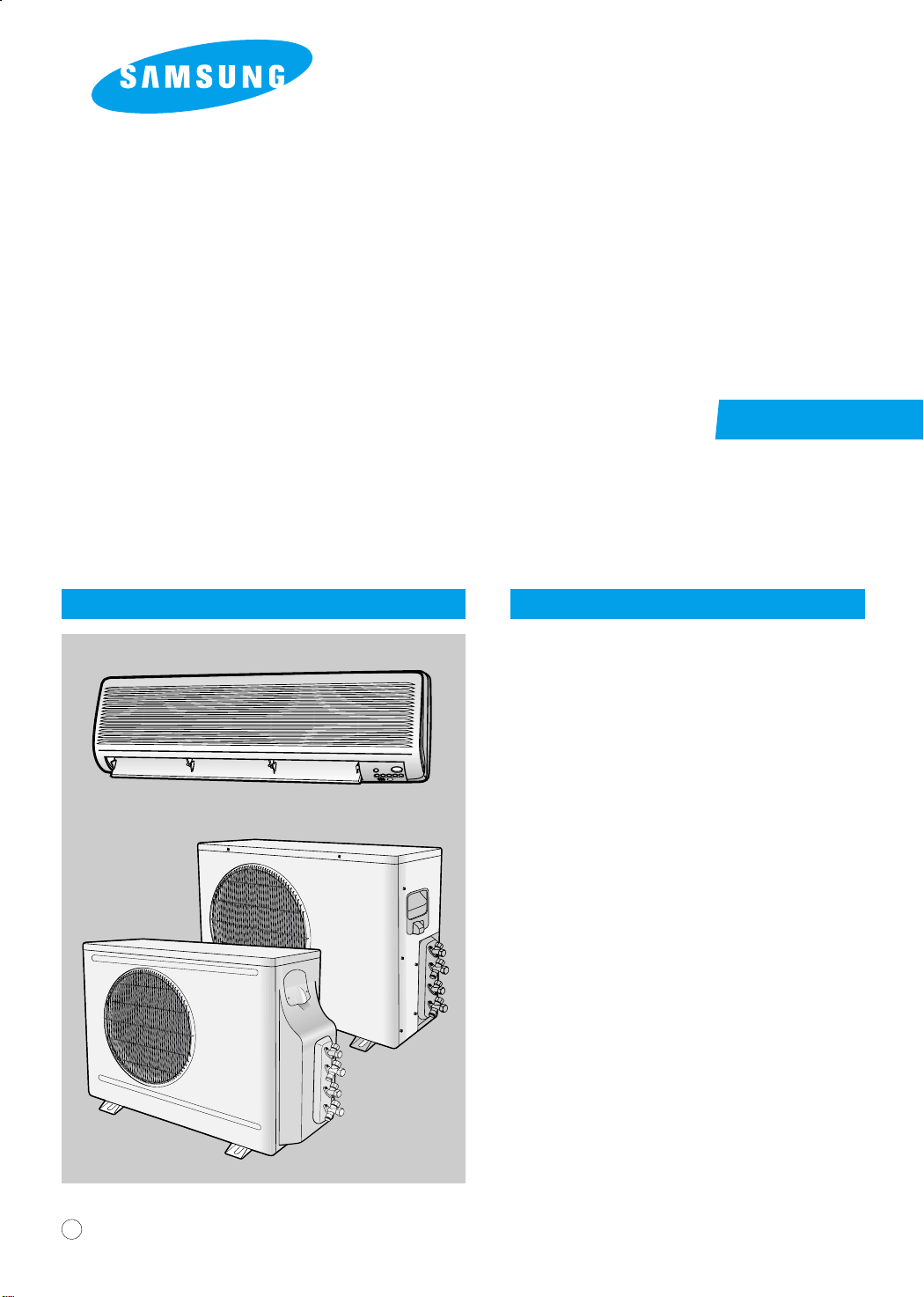
ROOM AIR CONDITIONER
INDOOR UNIT
AD26B1C13
AD18B1C09
SERVICE
OUTDOOR UNIT
UD26B1C2
UD18B1C2
Manual
CONTENTSAIR CONDITIONER
1. Installation
2. Disassembly and Reassembly
3. Troubleshooting
4. Exploded Views and Parts List
5. Refrigerating Cycle Block Diagrams
6. Wiring Diagrams
E DB98-05645A(1)
7. Schematic Diagrams
1. Installation
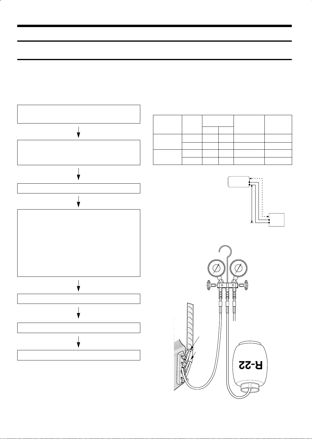
1-1 Refrigerant Refill Procedure
If connecting pipe of more than 5 metres is installed, additional refrigerant should be charged by extra
metre. You don’t have to charge additional refrigerant up to 5 metres of connecting pipe.
1. Remove the valve stem cap and service port of 3-way
valve.
2. Connect the charging hose of low pressure side of
Manifold gauge to the packed valve having a charging
port(1/2” Packed valve) as shown at the right figure.
3. Operate the unit at the cooling mode.
4. Slowly open the valve of the low pressure side of
Manifold gauge counterclockwise until the low pressure
of manifold gauge indicates 4.8 to 5.5 kg/cm
2
(68 a
78psi) at the high cool operation (1-unit operation) and
the standard temperature.
It is recommend that refrigerant should be slowly put in.
If the refrigerant is put in too quickly, compressor will be
damaged.
• Piping length and the height
Pipe Size
LIQUID GAS
AD26B1C13
AD18B1C09
Additional refrigerant charge
(R22,g)
• When length of the pipe is
over 5u by the unit, you
should charge
the refrigerant Formulas
A-UNIT : 20gx(La-5)/m
B-UNIT : 20gx(Lb-5)/m
(La:the length of A-unit’s
pipe Lb:the length of
B-unit’s pipe)
A-UNIT 1/4” 1/2” 15m(49ft 3in) 7m(23ft)
B-UNIT 1/4” 1/2” 15m(49ft 3in) 7m(23ft)
A-UNIT 1/4” 3/8” 15m(49ft 3in) 7m(23ft)
B-UNIT 1/4” 3/8” 15m(49ft 3in) 7m(23ft)
INDOOR UNIT
Max.piping
length
A
B
Max
height
B
A
OUTDOOR UNIT
5. Stop operation of the air conditioner.
6. Disconnect the charge hose of manifold gauge.
7. Close the cap of each valve.
INDOOR
A-UNIT
INDOOR
B-UNIT
1
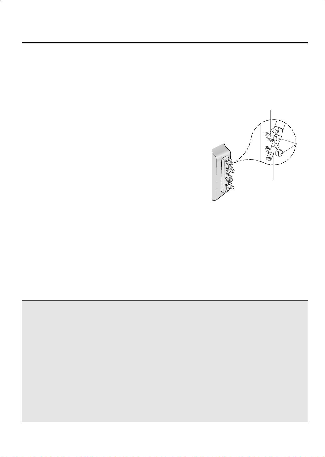
1-2 “Pump down” Procedure
1. Confirm that both the 2-way and 3-way valves are set to
the open position.
(1) Remove the valve stem caps.
(2) Be sure to use a hexagonal wrench to operate the Gas
side valve stems.
2. Operate the unit for 10 to 15 minutes.
3. Stop operation and wait for 3 minutes, then connect the
charge set to the service port of the 3-way valve.
(1) Connect the charge hose with the push pin to the ser-
vice port.
4. Air purging of the charge hose.
(1) Open the low-pressure valve on the charge set slightly
to air purge from the charge hose.
5. Set the liquid side 2-way valve to the closed position.
6. Operate the air conditioner at the cooling cycle and stop
operation immediately after setting the 3-way valve to the
closed position when the gauge indicates 0 kg/cm2G.
If the unit can not be operated at the Cooling Mode(weater
is rather cool), operate the unit at the Trubo Mode.
So that the unit can be operated.
7. Disconnect the charge set, and mount the both 3-way
valve’s stem nuts and the service port cap.
2-Way Valve
Cap
3-Way Valve
Relocation of the air conditioner
• Refer to this procedure when the unit is relocated.
1. Carry out the pump down procedure
(refer to the details of ‘pump down’).
2. Remove the power cord.
3. Disconnect the assembly cable from the
indoor and outdoor units.
4. Remove the flare nut connecting the indoor
unit and the pipe.
At this time, cover the pipe of the indoor
unit and the other pipe using a cap or vinyl
plug to avoid foreign material entering.
2
5. Disconnect the pipe connected to the outdoor unit.
At this time, cover the valve of the outdoor
unit and the other pipe using a cap or vinyl
plug to avoid foreign material entering.
6. Make sure you do not bend the connection
pipes in the middle and store together with
the cables.
7. Move the indoor and outdoor units to a new
location.
8. Remove the mounting plate for the indoor
unit and move it to a new location.
2. Disassembly and Reassembly
Stop operation of the air conditioner and remove the power cable before repairing the unit.
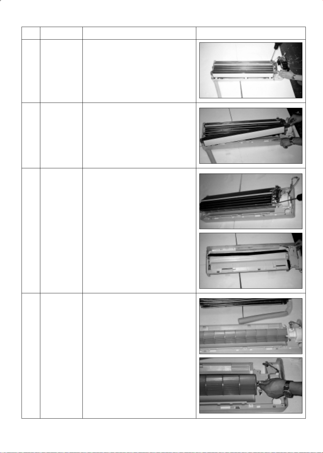
2-1 Indoor Unit
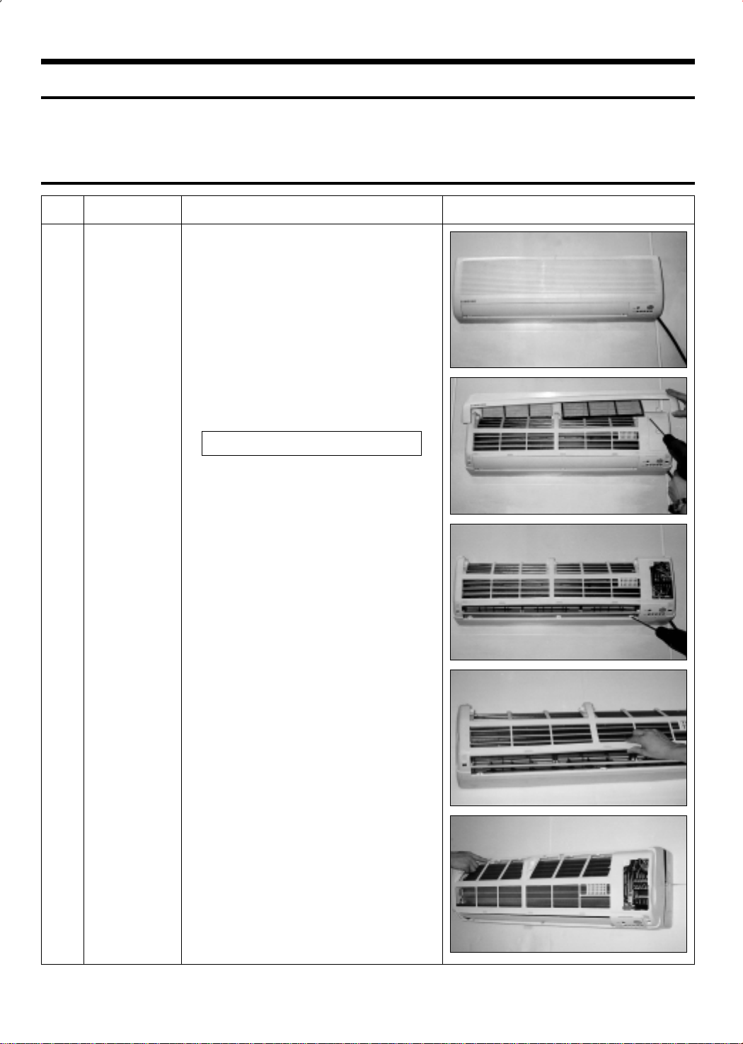
No Parts Procedure Remark
Front Grille1 1) Stop the air conditioner operation and block the
main power.
2) Separate tape of front panel upper.
3) Contract the second finger to the left, and right
handle and pull to open the inlet grille.
4) Take the left and right filter out.
*Taking off the deodorizing filter.
5) Loosen one of the right fixing screw and separate the terminal cover.
6) Loosen three fixing screws of front grille.
7) Pull the upper left and right of discharge softly
for the outside cover to be pulled out.
8) Pull softly the lower part of discharge and push
it up.
Caution;
Assemble the front panel and fix the
hooks of left and right.
3
No Parts Procedure Remark
2
3
4
Electrical Parts
(Main PCB)
Ass’y Tray Drain.
Heat Exchanger
1) Do “1”above.
2) Take all the connector of PCB upper side out.
(Inclusion Power cord)
3) Separate the outdoor unit connection wire from
the terminal block.
4) If pulling the Main PCB up. it will be taken out.
1) Do “1”, “2”, above.
Separate the drain hose from the extension
drain hose.
2) Pull tray drain out from the back body.
1) Do “1” and “2”, “3”, above.
2) Loosen two fixing earth screws of right side.
3) Separate the connection pipe.
4) Separate the holder pipe at the rearside.
5
Fan Motor and
Cross Fan
5) Loosen the three fixing screws of right and left
side.
6) Lifting the heat exchanger up a little to push the
up side for separation from the indoor unit.
1) Do “1”, “2”, ”3”, “4”, above.
2) Loosen the fixing two screws and separate the
motor holder.
3) Loosen the fixing screw of fan motor.
(By use of M3 wrench)
4) Separate the fan motor from the fan.
5) Separate the fan from the left holder bearing.
4
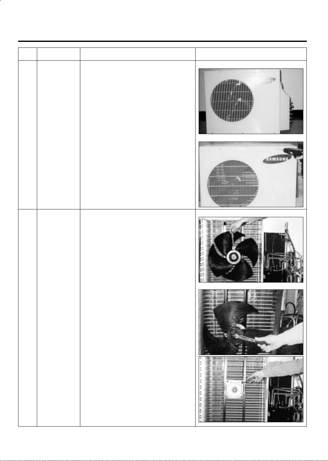
2-2 Outdoor Unit
No Parts Procedure Remark
1
2
Cabinet
Fan Motor
&
Propeller Fan
1) Turn off the unit and remove the power cable.
2) Remove the top cover.
3) Remove the control box cover.
4) Unplug the ass'y cable.
5) Remove the cabi-side.
6) Remove the cabi-front.
* When you assemble the parts, check if the
each parts and electric connectors are fixed
firmly.
1) Do Procedure “1” above.
2) Remove the nut flange.
(Turn to the right to remove as it is a left turned
screw)
3) Disassemble the propeller fan.
<UD26B1C2>
<UD18B1C2>
<UD26B1C2>
<UD18B1C2>
5
3. Troubleshooting
3-1 Items to be checked first
1) The input voltage should be rating voltage ±10% range.
The airconditioner may not operate properly if the voltage is out of this range.
2) Is the link cable linking the indoor unit and the outdoor unit linked properly?
The indoor unit and the outdoor unit shall be linked by 5 cables.
Check the terminals if the indoor unit and outdoor unit are properly linked by the same number
of cables. Otherwise the airconditioner may not operate properly.
3) When a problem occurs due to the contents illustrated in the table below it is a symptom not
related to the malfunction of the airconditioner.
NO Operation of air conditioner
1 The STD operation indication LED blinks when a
power plug of the indoor unit is plugged in for the first time.
2 In a COOL operation mode, the compressor does not
operate at a room temperature higher than the setting
temperature that the IN DOOR FAN should operate.
In a HEAT operation mode, the compressor does not
operate at a room temperature lower than the setting
temperature that indoor fan should operate.
3 Fan speed setting is not allowed in AUTO or DRY mode.
4 Compressor stops operation intermittently in DRY mode.
5 Compressor of the outdoor unit is operating although it is
turned off in a HEAT mode.
6 Timer LED only of the indoor unit lights up and the
air conditioner does not operate.
7 The compressor and indoor fan stop intermittently in HEAT
mode.
8 Indoor fan and outdoor fan stop operation intermittently in
a HEAT mode.
Explanation
It indicates power is on. The LED stops blinking if the operation
ON/OFF button on the remote control unit is pushed.
In happens after a delay of 3 minutes when the compressor is
reoperated. The same phenomenon occurs when a power is on.
As a phenomenon that the compressor is reoperated after a delay
of 3 minutes, the indoor fan is adjusted automatically with reference to a temperature of the air blew
The speed of the indoor fan is set to LL in DRY mode.
Fan speed is 5 steps is selected automatically in AUTO mode.
Compressor operation is controlled automatically in DRY mode
depending on the room temperature and humidity.
When the unit is turned off while de-ice is activated, the compressor continues operation for up to 9 minutes (maximum) until
the deice is completed.
Timer is being activated and the unit is in ready mode.
The unit operates normally if the timer operation is cancelled.
The compressor and indoor fan stop intermittently if room temperature exceeds a setting temperature in order to protect the compressor from overheated air in a HEAT mode.
The compressor operates in a reverse cycle to remove exterior ice
in a HEAT mode, and indoor fan and outdoor fan do not operate
intermittently for within 20% of the total heater operation
9 The compressor stops intermittently in a COOL mode or DRY
mode, and fan speed of the indoor unit decreases.
6
The compressor stops intermittently or the fan speed of the indoor
unit decreases to prevent inside/outside air frozen depending on
the inside/outside air temperature.
4) Indoor unit observes operation condition of the air conditioner, and displays self diagnosis details
on the display panel.
NO
Display
Standard Timer Nature Power
(GREEN)
1
2
3
4
5
6
7
X
(GREEN)
X
X
(GREEN)
(GREEN)
X
X
X
X
X
X
X
Self Diagnosis
Restore from power failure (input initial power)
X
Indoor unit Room sensor Error (open or short)
X
Indoor unit heat exchanger temperature sensor Error (open or short)
X
Indoor fan malfunctioning (for speed is below 450rpm)
X
In case that the communication between the indoor unit and outdoor unit is not made
X
for 60 seconds
Outdoor sensor Error (open or short)
- Outdoor sensor
X
- Pipe sensor A, B
The malfunction ot 4way valve in heat mode operation.
7
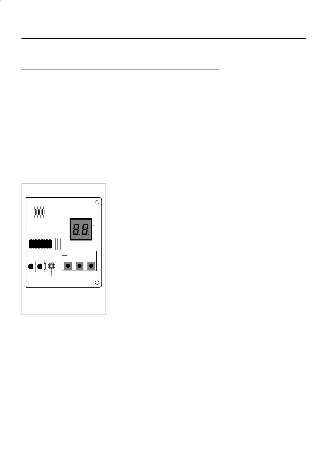
3-2 Checking and Testing Operations (Outdoor Unit)
C
a
b
TEST OPERATING
CB
A
To complete the installation, perform the following checks and tests to ensure that
the air conditioner is operating correctly.
1. Review all the following elements in the installation:
• Installation site strength
• Piping connection tightness to detect any gas leakages
• Connection wiring
• Heat-resistant insulation of the piping
• Drainage
• Earthing wire connection
• Correct operations (follow the steps below)
• Room select switch in the indoor unit
2. Apply the power to the outdoor unit.
- Check the fuse (250V~, 5A) : The fuse is open when the power line (L1, N2) is short.
OUTDOOR UNIT
A : PCB display
B : Red LED
C : PCB switch
3. Check the connection of PCB communication of outdoor unit.
(Check whether the red LED of outdoor unit PCB is flickering.)
• The communication lamp is flickering after the display of each
unit on the outdoor PCB display part. (every one second).
LED is not flikering, if the connection is bad or the room select
switch is located in the wrong position.
- LED lamp (red) flickering after display of A (0.5 sec)
- LED lamp (red) flickering after display of b (0.5 sec)
- LED lamp (red) flickering after display of C (0.5 sec)
Note : PCB switch “C” is used for triple split multi air conditioner.
Result : If all of three units display lamps are flickering, the connection
wires and the room option connections are good.
8
If the lamp is not flickering, check as follows:
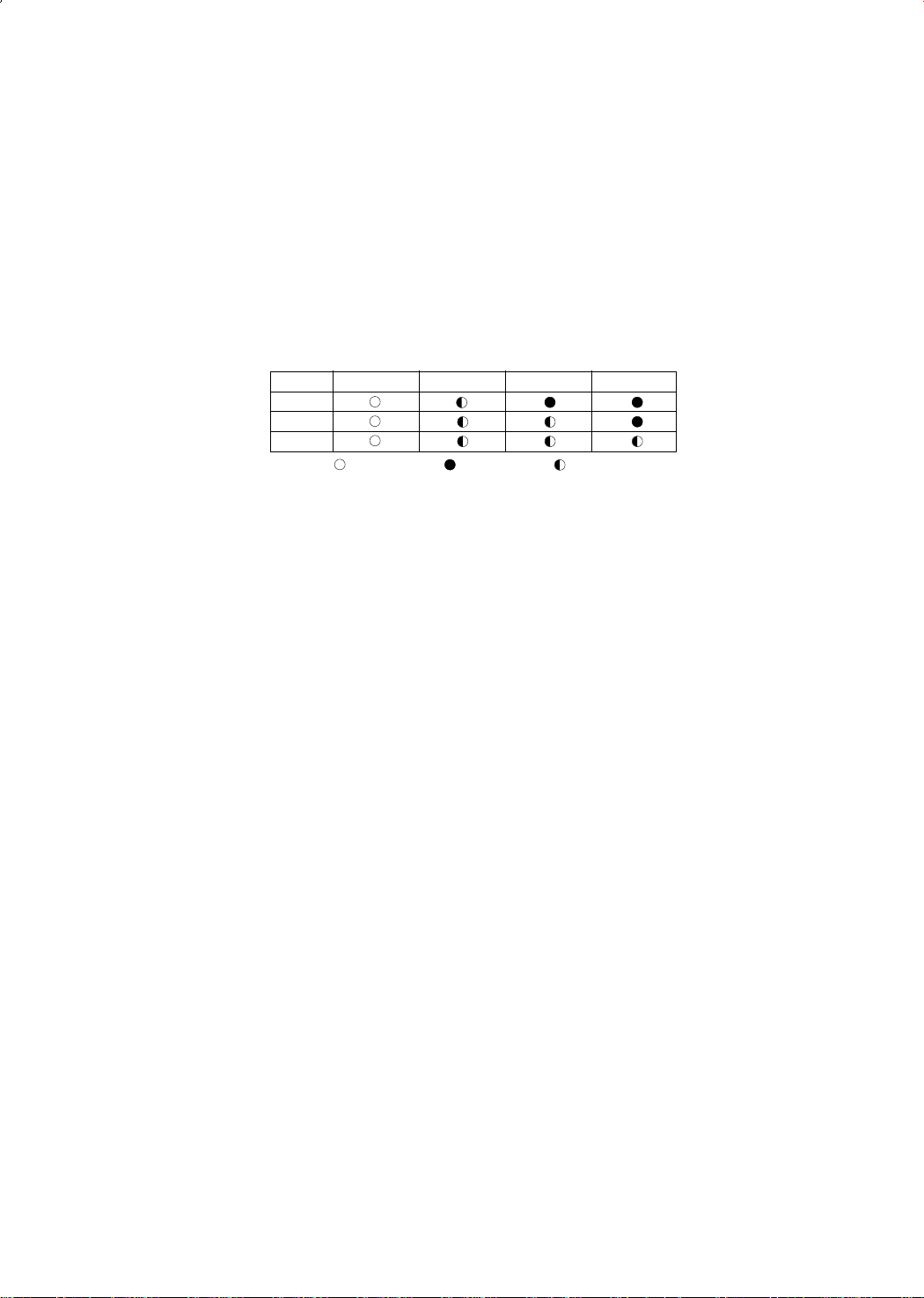
A. Check the display part of indoor unit of each unit (A,B) after outdoor unit PCB switch S/W-Ais on.
A. Check the status of each unit indoor room select switch.
A. (Adjust the select switch suitable to the unit A, B.)
A. - A unit : STANDARD LED on, TIMER LED flickering
A. - B unit : STANDARD LED on, TIMER and NATURE LED flickering
A. - C unit : STANDARD LED on, TIMER and NATURE, POWER LED flickering (In case of triple
split multi air conditioner)
UNIT
STANDARD TIMER NATURE POWER
A
B
C
Lamp ON
Lamp OFF Lamp Flasher
4. Check the test operation status by pressing the PCB switch
4. S/W-A and S/W-B of outdoor unit.
4. • Check the operation status by pushing the switch one at time.
4. • Perform the test operation only for the unit selected last.
4. • Check the pipe pressure and the other operation status during the test operation.
4. • Check items when the error occurs during the test operation (each unit)
- Check there is enough refrigerant.
- Check pipe connections.
9
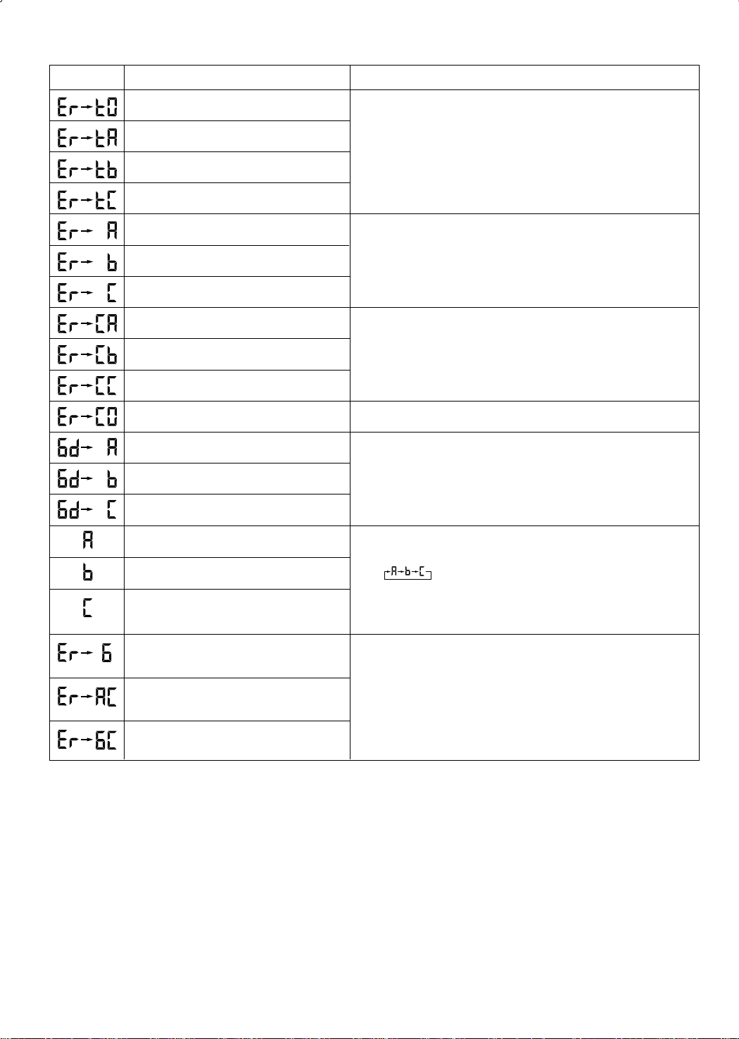
DISPLAY EXPLANATION
REMARK
Outdoor sensor error (Short/Open)
Outdoor A cond pipe sensor error (Short/Open)
Outdoor B cond pipe sensor error (Short/Open)
Outdoor C cond pipe sensor error (Short/Open)
A unit test operation error
B unit test operation error
C unit test operation error
A unit test communication error
B unit test communication error
C unit test communication error
A,B,C unit all communication error
A room test operation OK
B room test operation OK
Be sure to check after applying the power to the outdoor unit.
Display when the test operation finishes.
• When the pipe temperature difference of indoor unit
• (pipe temperature 4 minutes before - Actual pipe temperature)
• is less than 5˚C.
Be sure to check during the test operation.
Display of power application.
Display 4 minutes after the COMP is on.
C room test operation OK
Communication unit number display : A unit
Communication unit number display : B unit
Communication unit number display : C unit
(In case of triple split multi air conditioner)
Refrigerant leaks
High temperature of the A cond
High temperature of the B cond
•Normal operation
•Unit A,B and C are changed every one second.
•The communication lamp is flickering after display of each unit.
•(possibility to check the communication status)
•During the test operation the unit under test is on and off every 0.25s.
10
3-3 Fault Diagnosis by Symptom
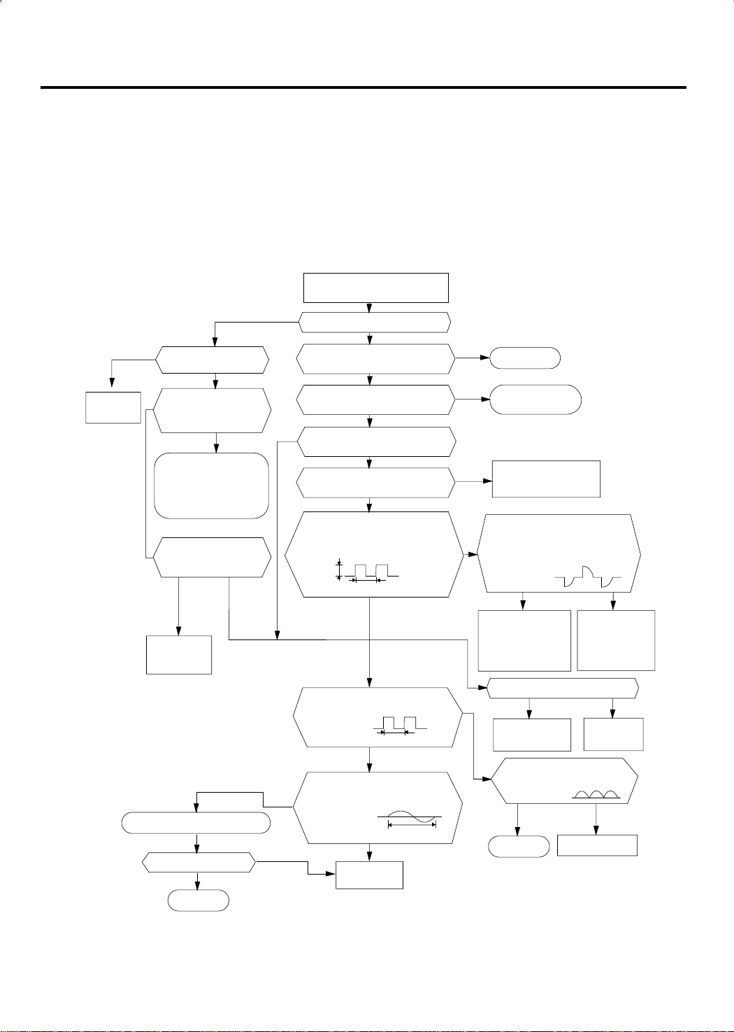
3-3-1 No Power (completely dead)-Initial diagnosis
1) Checklist :
(1) Is input voltage normal?
(2) Is AC power linked correctly?
(3) Is output voltage of DC regulator IC KA7805 (IC02) normal? (4.5VDC-5.5VDC)
2) Troubleshooting procedure
Remove power cord and plug in
again in approx. 5 seconds
YES
Replace
PCB display
Is DC voltage of PCB
display normal?
NO
Is rating voltage ±10%
range applied to the
primary side (~,~)
of the “BD71”
NO
•Check linkage between
power cord and
terminal tap
•Check fuse
Is 14~18VAC appear in
the secondary side (+, -)
of “BD71”
NO
Replace
SMPS PARTS
Replace resonator (X301)
Is operation normal?
YES
YES
OK
NO
Is operation lamp blinking?
Does operation start when
run/stop button on the remote
controller unit pushed?
Is transmission display of the
remote controller unit blinking?
Is "beep"sound heard from the
NO
Is DC voltage of the PCB module
5VDC Is voltage of #60 (indoor fan)
DC5V
Is voltage at #52 terminal of the
Are voltage at #48 and #49 of the
NO
NO
main unit?
normal?
of the micom normal?
10ms
micom normal?
micom normal?
Replace micom
YES
NO
YES
YES
YES
NO
YES
YES
10ms
250ns
YES
NO
NO
YES
NO
Normal
Refer to remote control
unit fault diagnosis
Replace PCB module.
Is voltage at SS71(indoor fan)
Check connections
compressor 4-way
valve, outdoor fan and
indoor fan.
Is output voltage of ICO2 normal?
Check PCB pattern.
Replace main PCB.
Is voltage output terminal of
TLP180(PC02) normal?
YES
OK
DC12V
YES
Replace RY71,
RY73, RY72 and
YES
Replace ICO2
Replace TLP180(pc02)
NO
SS71
NO
NO
11

3-3-2 When the power voltage is not available
1) Inspection items
(1) Is the power voltage is normal? (The rating voltage ±10% range)
(2) Is the power cord is correctly connected and is the contact good?
(3) Does the sound “ting” come out with the operation lamp (green) flickering when the
power is applied?
If it is not flickering, do inspect and repair in accordance with the following inspection
sequence.
2) Inspection sequence
Is the operation lamp of
No trouble
(normal)
YES
indoor unit on when the
operation /stop button of
remote controller is
pressed?
NO
YES
Is the operation lamp flickering with the
Apply the power
sound of “ting”?
NO
Check of remote
controller
Normal
Is the communication
NO
YES
signal of remote
controller surely sent
and received ?
Is there no problem
between the connector of
Ass’y display PCB and the
receiving module?
Replace of
Ass'y display PCB
YES
NO
Is the outdoor power connected normally?
YES
Is the fuse (F701, 250V, 3.15A) of PCB open?
NO
Is the voltage at Socondary side of transformer
of PCB (TN71)? (AC15V~AC25V)
YES
Is the output voltage of voltage regulator
IC (KA 7812) DC 10V and 12V?
YES
Is the output voltage of electrostatic voltage
regulator IC (KA 7805) DC 4.5 V - 5.5 V?
YES
NO
YES
NO
NO
NO
Check of the installation
method and electrical circuit
Replace the fuse (250V, 3.15 A)
Transformer is out of
order - replace
Repair and replace the power
source rectifying diode (D101-
D105) and KA7812.
KA7805 is out of order - replace
12
Replace the main PCB of indoor unit

3-3-3 No Power (Outdoor unit)
1) Inspection items
(1) Á Is the power source normal (The rating Voltage ±10% range)?
(2) Is the outdoor power connected normally? ((1) of terminal : L, (2) of terminal : N,
(3) of terminal : communication) ?
(3) Check whether the display of outdoor PCB(SEG1) is shown in the order of A- B - C when the
power is applied.
If the display (SEG 1) is not shown the inspection and repair shall be performed in the sequence
of the following:
2) Inspection sequence
Normal of
outdoor PCB
Replace the
transformer
Measurement of resistance
NO NO
Assemble the transformer
YES YES
PCB and whether
the LED 1 is contin-
uously flickering.
NO
Replace the fuse
(F701) 250V 3.15A.
of power transformer
Are they as follows?
1st side 190 ~ 210Ω
2nd side 0.9 ~ 1.1Ω
YES
in the normal way.
Check the
communication of
Put the power off and put it on after
Is the display of PCB shown in the
Are the power cord ((1) L, (2) N) and
communication line (3) of outdoor terminal
Is the terminal of PCB terminal (RY71, 72, 73)
are assembled in the correct position?
YES
Insert the primary side of power transformer
in the terminal GT01 and then is the voltage
of secondary side normal? (AC 15V- AC 25V)
Is the fuse (F101, 250V 2 A) blown out?
Check whether the output voltage of
Check whether the output voltage of
5 seconds.
sequence of A-B-C?
NO
block connected correctly?
YES
YES
Is the fuse open? (F701)
NO
YES
NO
IC01 (KA 7812) is DC 12V.
YES
IC02 (KA 7805) is DC 5V.
YES
NO
YES
NO
NO
Reinstall the power cord and
communication line with the
reference of installation manual.
After watching the display of
NO
PCB board, assemble the
color and shape of housing
correctly as follows:
BLK
WHT
RED
Replace the fuse F101
(250V 2 A).
Check and Replace the rectifying
diode of power side
(D101 - D104) and KA 7812.
Replace the IC 02 (KA7805)
BLK
WHT
RED
Replace the outdoor unit Ass'y main PCB.
13

3-3-4 When the fan of indoor unit does not operate
1) Inspection items
(1) Is the power voltage normal?
(2) Is the connector of indoor fan with the good contact? (CN73)
(3) Is the soldering status of running condenser (CR71) with the good contact?
(4) Is connector of the Hall IC with the good contact (CN 43) ?
(5) Is the indoor fan rotating when it is under operation mode?
(6) Is the FAN LED (green) flickering when the indoor fan stalled (for more than 15 seconds) and
the trouble condition of speed detecting part?
Put the power off and put it on after 5 seconds.
YES
Error occurs after the
indoor unit fan motor is
rotating for 15 seconds?
(FAN Lamp flickering)
YES
Replacement of
indoor unit fan motor.
Is the operation lamp flickering for 3 minutes and
YES
If the operation /stop button of the remote controller
is pressed, is the operation lamp flickering and then is
the indoor fan rotating after 5~6 seconds?
YES
Is AC 120V and higher shown across the indoor fan
then put off?
YES
YES
connector (CN73) ?
NO
NO
NO
If the power is not available
(indoor unit), item no 3-3-1.
Replace of indoor unit PCB Ass'y.
NO
Is the type of MICOM (IC 04) Pin no.
63 old type ?
120Hz
YES
Is the pin no. 12 of IC 06 (KID 65003)
the old type?
120Hz
YES
Is the pin no 25 of MICOM
the old type?
Replace the indoor unit PCB Ass'y due to the
Micom defect.
NO
NO
Replace the IC 06 (KID 65003)
and SS71(G3MB202pl).
Replace Q401 (Ksc 945Y).
14

3-3-5 When the outdoor unit fan does not operate
1) Inspection items
(1) The outdoor unit fan motor operates only when the operating conditions are satisfied and is selected
by the RY74(LOW) and PY75(HI) to rotate.
(2) Is the power voltage normal?
(3) Is the contact of outdoor unit fan motor (CN 73) good?
(4) Is the winding resistance of outdoor unit fan motor 58Ω at Hi side and 143Ω at low side?
(5) The outdoor unit fan motor operates with Hi at over 28°C and low at below 26°C during the cooling
operation, and operates with Hi at below 14°C and low at over 15°C during the heating operation.
2) Inspection sequence
Apply the power to the outdoor unit and operate the indoor unit.
Is the indoor unit under operating conditions?
YES
Is it operating in the High speed?
NO
Is the voltage shown across the connector (1)↔(3) ((1)↔(5))
(the rating voltage ±10% range)?
NO
Is no. 11 ( 12) of IC 06 at low? (DC 0.7 V)
NO
Is pin no. 48(49) of IC 04 (MICOM) at High (DC 5 V)?
NO
Is the outdoor unit fan motor under the operating
conditions?
NO
Normal
NO
YES
YES
YES
YES
YES
Check the winding resistance of outdoor unit fan
Defect of IC 04(MICOM) - replace the IC 04
Normal (operation off)
Normal
motor winding resistance → Replace
Contact bad of RY 74(Low), RY 75(High)
→ Replace
Defect of IC06 output
→ Replace
or PCB ass’y
* Operating specification of the FAN of outdoor unit
(1) When the COMP is under the COMP ON condition during the cooling and heating operation,
Hi or LOW operation is selected according to the temperature condition of outdoor room.
(2) When A room and B room are mixed to operate , it is always under low operation.
(3) Perform the comp ON/OFF control in the dry mode.
(4) When it is under the operation of anti-freezing, overload protection, defrost operation, it may
be Low, high or Off.
(5) Hi = High speed, Low = Low speed
15

3-3-6 When the UP/DOWN Louver Moter Does Not Operate. (Initial Diagnosis)
1) Checklist :
(1) Is input voltage normal?
(2) Is the UP/DOWN louver motor properly connected with the connector (CN61)?
2) Troubleshooting procedure
Remove power cord and plug in again in approx. 5 seconds.
Is operating lamp blinking?
YES
Does operation start when swing button of
the remote control unit pushed?
NO
Voltage at pin #33 ~ #36 of micom (ICO4) change?(Squarewave)
YES
Volatge at pin #13, #14, #15, #16 of IC05 (KID65003)
change?(Squarewave)
YES
UP/DOWN louver motor is faulty.
YES
Check as in the procedure "No Power parts".
Refer to page 11.
YES
Normal
NO
Micom (IC04) is faulty.
NO
Driver IC05 (KID65003) is faulty.
16

3-3-7 If Operation By Remote Control Unit Is Impossible. (Initial Diagnosis)
1) Troubleshooting procedure
Remove power cord and plug in again approx. 5 Seconds
Is operation lamp blinking?
YES
“ “ sound heard from the indoor unit when ON/OFF
button on the remote control unit pushed?
NO
Voltage of battery less than 2.5V (Remote Control Unit)?
NO
LCD display status of REMOCON normal?
YES
Transmission display lamp ( ) blinking when
ON/OFF button on the remote control unit pushed?
YES
Voltage at PIN #30 of Remocon Micom change?
YES
Voltage at collecter of Q601 or Q602 change?
YES
NO
Check as in the procedure “NO Power parts”.
YES
YES
NO
NO
NO
NO
Q601(C4375Y) or Q602(C1623Y) is faulty.
Refer to page 11.
Normal
Replace battery.
LCD is faulty.
Replace button.
Micom is faulty.
IR LED(CL-1L5EU) is faulty.
Voltage at pin #26 of micom (IC04) change (INDOOR UNIT)?
YES
Micom (IC04) is faulty.
NO
Receiver module is faulty.
17

3-3-8 When the 4 way valve (A,B) is not operating
1) Inspection items
(1) Are the 4 way valve A and B under the operating conditions?
(When the COMP A (4 way valve A ) and COMP B (4 way valve B) are on during the
heating operating)
(2) Is the power voltage normal?
(3) Is the connecting of 4 way valve A (CN 75) and B (CN 76) good?
2) Inspection sequence
Put off the outdoor unit power and put it on again after 5 seconds.
Select the heating operation of A(B) room by the remote controller.
Has 3 minutes passed after selection of A(B) room heating?
YES
Is the 4 way valve A(B) on?
NO
Is the voltage shown across the 4 way valve A(B) connector
(CN 75, CN 76) ?
NO
Is the pin no 47(46) of IC 04 ( MICOM) at high (DC 5V) ?
NO
Is the 4 way valve A (B) under operating conditions?
NO
Normal
NO
YES
YES
YES
YES
Defect of IC 04(MICOM) - replace the IC 04
Keep 4 way valve off.
Normal
Defect of RY 76 (RY 77) contact and coil
→ Replace the Relay
Defect of IC 06 (IC 07 ) output → Replace
or PCB ass’y
*4 way valve operating conditions
(1) During the defrost control, put the 4 way valve A(B) off.
(2) During the heating operation put the 4 way valve A(B) on.
(3) The changeover of heating to cooling : put the 4 way valve off immediately (in case of B and C room).
(4) The changeover of cooling to heating : it is on after 170 seconds delay.
18

3-3-9 When the compressor does not operate
1) Inspection items
(1) Is the COMP A under the operating conditions? (cooling operating of A, B(C) room)
(2) Is the power voltage normal? (the rating voltage ±10% range)
(3) Are the connector connection of COMP A(RY 72, 73) and B(RY 71) good?
(4) The COMP A(B) is operated on and off in accordance with the operating conditions of indoor
unit of A (B. C) room.
2) Inspection sequence
Apply the outdoor power and operate the indoor unit A(B, C)
Is the comp A under the operating condition?
Has 3 minutes passed COMP A(B) after the power initial
Is the voltage (the rating voltage ±10% range) shown
across the terminal of Comp A(B) power applied?
Is the voltage of pin no. 14, 13( 15) at low
Is the voltage of pin no. 50, 51 (52) of IC 04 (micom) at
Is comp A (B ) under the operating condition?
in the cooling mode.
YES
and COMP on/off
YES
Is comp A (B) on?
NO
NO
(DC 0.7V)?
NO
high (DC 5V)?
NO
NO
*Refer to the power measuring terminal
NO
NO
YES
YES
YES
YES
YES
Normal (comp A (B) off)
Keep Comp A (B) off
Normal
Defect of comp A (B) and running condenser
→ Replace
Defect of Ry 72, 73 (Comp B) and Ry 71(comp A)
contact and coil → Replace
Defect of IC 06 output
→ Replace
Defect of Ic 04 (micom)
→ Replace
Normal (comp A (B ) off)
* Comp A (B ) operating conditions
(1) Comp A : Comp on /off control in accordance with the Aroom during the heating and cooling
indoor unit operation
(2) Comp B : Comp on /off control in accordance with the B(C) room during the heating and cooling
indoor unit operation
* Comp A(B ) power measuring terminal
(1) Comp A measuring ; RY 73 (4) ´ RY 72 (4)
(2) Comp B measuring ; RY 71 (4) ´ RY 72 (4)
(3) Power input ; RY 72 (3) ´ RY 73(3)
BLK
WHT
RED
RY72
(4)
(3)
RY71
(3)
RY73
(3)
BLK
(4)
WHT
(4)
RED
19

3-4 Set up the Model option
The Method for Setting up the model option with remocon
• It is necessary to set up option code after replacing the main-PCB as a service parts.
Make sure that you can set up the option of code the remote controller after you replace the main
PBA otherwise, the unit won’t be working properly and all LED lamps on display will be flickering.
Step 1 : Preparing the remocon to main PCB option set
st
1
Remove the battery from the remocon.
2ndPress the temperature raise/down button simultaneously
and insert the battery again.
3rdMake sure the remocon display shown as .
Step 2 : Second stage preparation of the remocon option set.
❈ Note ; In case the wrong letter has been selected, continue to press the button until the correct letter appears.
st
1
If the first stage number “ ” appears on the display, proceed to the second stage.
nd
2
Every time the ! and & button, “ ” and “ ” each continue to appear.
rd
3
Whenever pressing the @, #, $, %, ^, *, (, ), 1, 2 button, the number increase from
0~9(0123456789) and A, b, C, d, E, F each time.
! If the first number is , it is correct otherwise press until
appear.
@ When pressing the button ~ appear on the display,
select one of them.
20
# When pressing the button ~ appear on the display,
select one of them.
$ When pressing the button ~ appear on the display,
select one of them.
% When pressing the button ~ appear on the display,
select one of them.
^ When pressing the button ~ appear on the display,
select one of them.

! If the first number is , it is correct otherwise press until
appear.
@ When pressing the button ~ appear on the display,
select one of them.
# When pressing the button ~ appear on the display,
select one of them.
$ When pressing the button ~ appear on the display,
select one of them.
% When pressing the button ~ appear on the display,
select one of them.
^ When pressing the button ~ appear on the display,
select one of them.
Step 3 : Reconfirming option set after completion
(in case of ex. 000000-1700b7)
After pressing selector for the mode, the display shown as .
After pressing selector for the mode, the display shown as .
Step 4 : Pressing the ON/OFF button ( )
direction of remote controller for unit, the sound “Ding” or “Diriring” is heard and the first
LED lamp on the left side is flickering at the same time, then the input of option is completed. (If the diriring sound isn’t heard, try again pressing the ON/OFF button.)
Step 5 : Unit operation test-run
First, Remove the battery from the remote controller.
Second, Re-insert the battery into the remote controller.
Third, Press ON/OFF key with the direction of remote controller for set.
• Error Mode
st
1
If all lamps of indoor unit are flickering, Plug out and plug in again and pressing ON/OFF key to retry.
nd
2
If the unit is not working properly or all lamps are continuously flickering after setting the option code, see
if the correct option code is set up for it’s model.
When pressing the operation ON/OFF key with the
21

<Table of the option code>
MODEL
AD26B1C13
AD18B1C09
OPTION CODE
015773-100373
015223-10020C
22

MEMO
23

4. Exploded Views and Parts List
17
16
14
22
9
7
21
3
4
5
6
19
20
8
12
25
13-4
23
13-3
13-2
13
13-1
11
10
2
1
15
18-1
18-5
18-4
18
18-6
18-6-1
18-2
18-3
24
4-1 Indoor Unit
24

■
Parts List
No.
1
2
3
4
5
6
7
8
9
10
11
12
13
13-1
13-2
13-3
13-3-1
13-3-2
13-4
14
15
16
17
18
18-1
18-2
18-3
18-4
18-5
18-6
18-6-1
19
20
21
22
23
24
25
CODE NO
DB64-00085A
DB63-00064B
DB95-00287K
DB63-00067A
DB92-00031L
DB67-00051A
DB67-00032A
DB63-00083A
DB94-00020A
DB60-20011A
DB31-00071B
DB32-00020A
DB93-01223A
DB93-00319B
DB65-00046A
DB93-00268A
2202-000780
DB32-00037A
DB39-00147A
DB94-00056E
DB94-00104A
DB61-00165A
DB70-00036A
DB94-00058F
DB94-00062E
DB66-00127B
DB66-00128A
DB66-00128B
DB63-00082A
DB95-20138A
DB31-10129A
DB61-40251A
DB67-60030A
DB96-01123K
DB96-01123J
DB94-40003A
DB93-00861B
DB70-00114A
DB63-00226A
Description
GRILLE AIR INLET
GUARD-AIR FILTER
FILTER CLEANER ASS´Y
COVER TEMINAL
ASS´Y PANEL
SPACER EVAP LOW
SPACER EVAP UP
COVER U BEND
ASS´Y FAN CROSS
BOLT SPECIAL
MOTOR FAN IN
THERMISTOR WIRE ASS´Y
ASS’Y CONTROL IN
ASS´Y PCB MAIN
TERMINAL BLOCK ASS´Y
ASS´Y PCB DISPLAY
C CERAMIC,MLC-AXIAL
MODULE REMOCON
CONNECT WIRE PCB
ASS´Y BACK BODY(RIGHT SIDE)
ASS´Y HOLDER MOTOR
HOLDER PIPE
PLATE HANGER
ASS´Y TRAY DRAIN(RIGHT SIDE)
ASS´Y DRAIN HOSE
BLADE H
BLADE V,A
BLADE V,B
SCREEN SAFETY WIRE
ASS´Y MOTOR STEPPING
MOTOR STEPPING; GSP 24RW
HOLDER SENSOR
SPRING SENSOR
ASS’Y CYCLE IN(EVAPORATOR)
ASS´Y BEARING
ASS´Y REMOCON
PLATE-KNOCKOUT
COVER TERMINAL BLOCK
Q’TY
AD18B1C09 AD26B1C13
1
2
1
1
1
1
1
1
1
1
1
1
1
1
1
1
1
1
1
1
1
1
1
1
1
1
3
6
1
1
1
1
1
1
1
1
1
1
1
2
1
1
1
1
1
1
1
1
1
1
1
1
1
1
1
1
1
1
1
1
1
1
1
1
3
6
1
1
1
1
1
1
1
1
1
1
REMARK
25

4-2 Outdoor Unit
12
15
8
17
3
4
5
7
6
9(9-1~9-2)
14(14-1~14-4)
2
1
10
13(13-1~13-6)
16(16-1~16-7)
11
4-2-1 UD26B1C2
26

■
Parts List
No.
CODE NO
Description Specification
Q’TY
REMARK
UD26B1C2
1
2
3
4
5
6
7
8
9
9-1
9-2
10
11
12
13
13-1
13-2
13-3
13-4
13-5
13-6
14
14-1
14-2
14-3
14-3-1
14-4
14-4-1
15
16
16-1
16-2
16-3
16-4
16-5
16-6
16-7
17
DB90-00075D
DB90-20207A
DB67-50067A
DB31-00095A
DB61-20093A
DB63-30027C
DB94-50041D
DB90-10574B
DB90-40120B
DB63-10434B
DB63-10433B
DB90-00742A
DB96-01356K
DB63-30110J
48D135IU1EL
DB60-30018A
DB60-30028A
DB63-10165D
DB63-20002A
DB73-00067A
DB35-00015H
DB99-00224A
DB99-00225A
DB99-00226A
DB99-00222A
DB95-00243C
DB99-00223A
DB95-00243D
DB32-00025B
DB93-01232A
2301-001379
2501-001237
DB26-10070A
DB61-00585A
DB61-00584A
DB65-40072F
PD-UD18B1-01
DB95-00329A
ASSY CABI FRONT
ASSY BASE OUT
FAN PROPELLER
MOTOR FAN
BASE MOTOR
GUARD COND
ASSY PARTITION
ASSY CABI SIDE
ASSY COVER
COVER
COVER CONTROL
ASSY CABI UPPER
ASSY COND-UNIT
SCREEN GUARD
ROTARY COMPRESSOR
NUT FLANGE
NUT WASHER
COVER TERMINAL
GASKET
GROMMET ISOLATOR
OLP
ASSY VALVE
ASSY VALVE CHECK A
ASSY VALVE CHECK B
ASSY VALVE 4WAYA
ASSY SOLENOIDE COIL
ASSY VALVE 4WAY B
ASSY SOLENOIDE COIL
THERMISTOR OUT ASS’Y
ASSY CONTROL OUT
C-OIL
C-OIL
TRANS POWER
CASE PCB
CASE CONTROL OUT
TERMINAL BLOCK
ASSY PCB PARTS
ASSY HEATER
ASS’Y
ASS’Y
AS+G/F20%, D495
OSM-738SRC
SGCC-M, T1.2
SC-90073T
ASS’Y
ASS’Y
ASS’Y
PP
PP
ASS’Y
UD26B1C2
P.E.H 100%
48D135IU1EL
PI0.8, M5
HEX, 2C, M8
PBT, 2.5
EPDM, T0.8
NR 40˚
RAC12074-9622
ASS’Y
ASS’Y
ASS’Y
ASS’Y
ASS’Y
ASS’Y
ASS’Y
103AT
ASS’Y
4uF, 450V
35uF, 450V
DC17, AC230, 600mA
ABS
SGCC-M, T0.8
ASS’Y
ASS’Y
ASS’Y
1
1
1
1
1
1
1
1
1
1
1
1
1
1
2
2
6
2
2
6
2
1
1
1
1
1
1
1
1
1
1
2
1
1
1
1
1
2
27

4-2-2 UD18B1C2
15
16(16-1~16-7)
13(13-1~13-6)
14(14-1~14-4)
9
3
1
10
4
6
5
7
8
2
11
17
12
28

■
Parts List
No.
CODE NO
Description Specification
Q’TY
REMARK
UD18B1C2
1
1-1
2
3
4
5
6
7
8
9
10
11
12
13
13-1
13-2
13-3
13-4
13-5
13-6
14
14-1
14-2
14-3
14-3-1
14-4
14-4-1
15
16
16-1
16-2
16-3
16-4
16-5
16-6
16-7
17
DB90-00734A
DB63-00320A
DB90-00733A
DB67-50063A
DB31-00001A
DB61-20008C
DB63-00343A
DB94-00180A
DB90-00737B
DB90-40176B
DB90-00742A
DB96-01717B
DB61-00821D
44B102IU2EL
DB60-30018A
DB60-30028A
DB63-10165D
DB63-20002A
DB73-00070A
DB35-00015C
DB99-00231A
DB99-00227A
DB99-00228A
DB94-00229A
DB95-00243A
DB99-00230A
DB95-00243B
DB32-00025A
DB93-01234A
2301-001370
2501-001235
DB26-10070A
DB61-00585A
DB61-00891A
DB65-40072F
PD-UD18B1-01
DB95-00329B
ASSY CABI FRONT
GUARD FAN
ASSY BASE OUT
FAN PROPELLER
MOTOR FAN
BASE MOTOR
GUARD COND
ASSY PARTITION
ASSY CABI SIDE RH
ASSY COVER CONTROL
ASSY CABI UPPER
ASSY COND-UNIT
GUIDE SCREEN
ROTARY COMPRESSOR
NUT FLANGE
NUT WASHER
COVER TERMINAL
GASKET
GROMMET ISOLATOR
OLP
ASSY VALVE
ASSY VALVE CHECK A
ASSY VALVE CHECK B
ASSY VALVE 4WAYA
ASSY SOLENOIDE COIL
ASSY VALVE 4WAY B
ASSY SOLENOIDE COIL
THERMISTOR OUT ASS’Y
ASSY CONTROL OUT
C-OIL
C-OIL
TRANS POWER
CASE PCB
CASE CONTROL OUT
TERMINAL BLOCK
ASSY PCB PARTS
ASSY HEATER
ASS’Y
SC-90073T
ASS’Y
AS+G/F20%, D405
IC-9630SLJ5A
SGCC-M,T1.2
SC-90073T
ASS’Y
ASS’Y
ASS’Y
ASS’Y
ASS’Y
P.E.H 100%
44B092JW1EL
PI0.8, M5
HEX, 2C, M8
PBT, 2.5
EPDM, T0.8
NR 35˚
RAC12067-9622
ASS’Y
ASS’Y
ASS’Y
ASS’Y
ASS’Y
ASS’Y
ASS’Y
103AT
ASS’Y
2.5uF, 450V
25uF, 450V
DC17, AC230, 600mA
ABS
SGCC-M, T0.8
ASS’Y
ASS’Y
ASS’Y
1
1
1
1
1
1
1
1
1
1
1
1
1
2
2
6
2
2
6
2
1
1
1
1
1
1
1
1
1
1
1
1
1
1
1
1
2
29

4-3 ASS’Y CONTROL IN (DB93-01223A)
■
Parts List
No
30
10
11
Description
1
2
3
4
5
6
7
8
9
HOLDER CONTROL
ASS’Y MAIN PCB
TERMINAL BLOCK ASSY
ASSY DISPLAY PCB
CONNECTOR WIRE PCB U/D
HOLDER CLAMP IN
SEAL CONTROL SIDE
SEAL H/CONTROL FRONT
SCREW MACHINE
LABEL
CORE
Specification
DB61-00160B
DB93-00319B
DB65-00046A
DB93-00268A
DB39-00147A
DB61-00219A
DB72-10191T
DB72-00127V
-
-
DB31-40005A
Remark

5. Refrigerating Cycle Block Diagram
INDOOR UNIT OUTDOOR UNIT
2Way valve
(A)
Cross fan
Heat
exchanger
(Evaporator)
T1
(B)
T2
Liquid side
Cross fan
Gas side
Capillary tube
Compressor-A
3Way valve
Check valve
Capillary tube
Propeller fan
Heat
exchanger
(Condenser)
Compressor-B
4Way valve
Refrigerating cycle temperature and pressure
STD Pressure Piping Temp.(°F) Temp. Condition (°F)
Operating Condition (psi)
T1 T2
3-WAY V/V DB WB DB WB
Standard 57-71 50-54 50-54 80 67 95 75
Cooling Max over load - 61-64 61-64 80 67 115 75
Low temp. - 34-39 34-39 67 57 67 57
Standard 242-284 90-97 140-158 70 60 47 43
Heating Max over load - 97-104 149-167 80 - 75 65
Deice - 82-90 104-113 70 60 35 33
Indoor Outdoor
31

6. Wiring Diagrams
6-1 Indoor Unit
32

6-2 Outdoor Unit
33

7. Schematic Diagrams
7-1 Indoor Unit
■ AS07A5(6)MA / AS09A5(6)MA
34 35

7-2 Outdoor Unit
■ AS07A5(6)MA / AS09A5(6)MA
3736

ELECTRONICS
Printed in Korea.
 Loading...