

Samsung AD26A1C13, AD18A1C09, UD26A1C2, UD18A1C2 Service Manual

ROOM AIR CONDITIONER
INDOOR UNIT
AD26A1C13
AD18A1C09
SERVICE
OUTDOOR UNIT
UD26A1C2
UD18A1C2
Manual
CONTENTSAIR CONDITIONER
1. Installation
2. Disassembly and Reassembly
3. Troubleshooting
4. Exploded Views and Parts List
5. Refrigerating Cycle Block Diagrams
6. Wiring Diagrams
E DB68-31043A(5)
7. Schematic Diagrams
1. Installation
1-1 Refrigerant Refill Procedure
If connecting pipe of more than 10 metres is installed, additional refrigerant should be charged by extra
metre. You donÕt have to charge additional refrigerant up to 10 metres of connecting pipe.
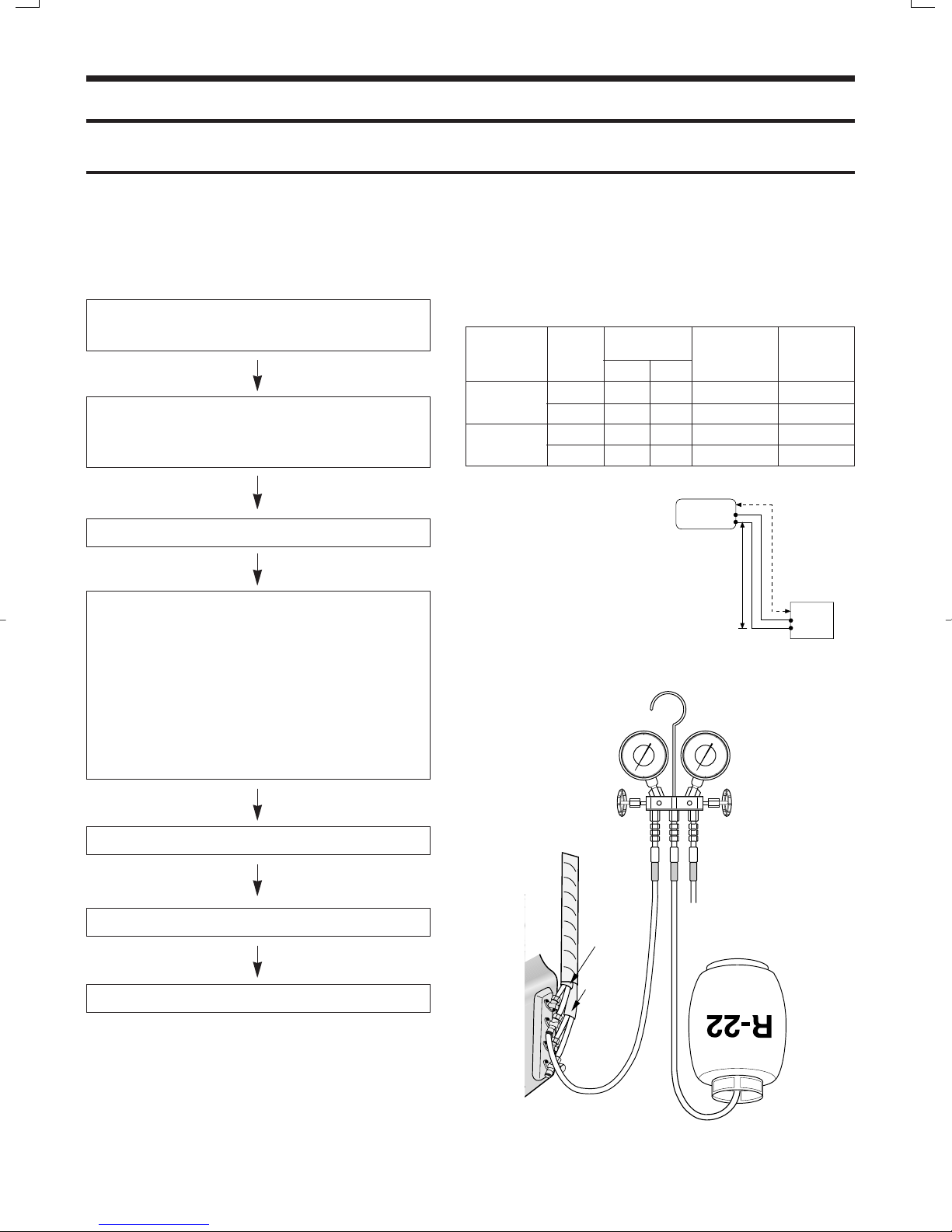
1. Remove the valve stem cap and service port of 3-way
valve.
2. Connect the charging hose of low pressure side of
Manifold gauge to the packed valve having a charging
port(1/2Ó Packed valve) as shown at the right figure.
3. Operate the unit at the cooling mode.
4. Slowly open the valve of the low pressure side of
Manifold gauge counterclockwise until the low pressure
of manifold gauge indicates 4.8 to 5.5 kg/cm
2
(68 a
78psi) at the high cool operation (1-unit operation) and
the standard temperature.
It is recommend that refrigerant should be slowly put in.
If the refrigerant is put in too quickly, compressor will be
damaged.
¥ Piping length and the height
Pipe Size
LIQUID GAS
AD26A1C13
AD18A1C09
Additional refrigerant charge
(R22,g)
¥ When length of the pipe is
over 5u by the unit, you
should charge
the refrigerant Formulas
A-UNIT : 10gx(La-10)/m
B-UNIT : 10gx(Lb-10)/m
(La:the length of A-unitÕs
pipe Lb:the length of
B-unitÕs pipe)
A-UNIT 1/4Ó 1/2Ó 15m(49ft 3in) 3m(9ft 10in)
B-UNIT 1/4Ó 1/2Ó 15m(49ft 3in) 3m(9ft 10in)
A-UNIT 1/4Ó 3/8Ó 15m(49ft 3in) 3m(9ft 10in)
B-UNIT 1/4Ó 3/8Ó 15m(49ft 3in) 3m(9ft 10in)
INDOOR UNIT
Max.piping
length
A
B
Max
height
B
A
OUTDOOR UNIT
5. Stop operation of the air conditioner.
6. Disconnect the charge hose of manifold gauge.
7. Close the cap of each valve.
INDOOR
A-UNIT
INDOOR
B-UNIT
1

1-2 ÒPump downÓ Procedure
1. Confirm that both the 2-way and 3-way valves are set to
the open position.
(1) Remove the valve stem caps.
(2) Be sure to use a hexagonal wrench to operate the Gas
side valve stems.
2. Operate the unit for 10 to 15 minutes.
3. Stop operation and wait for 3 minutes, then connect the
charge set to the service port of the 3-way valve.
(1) Connect the charge hose with the push pin to the ser-
vice port.
4. Air purging of the charge hose.
(1) Open the low-pressure valve on the charge set slightly
to air purge from the charge hose.
5. Set the liquid side 2-way valve to the closed position.
6. Operate the air conditioner at the cooling cycle and stop
operation immediately after setting the 3-way valve to the
closed position when the gauge indicates 0 kg/cm2G.
If the unit can not be operated at the Cooling Mode(weather is rather cool), operate the unit at the Trubo Mode. So
that the unit can be operated.
2-Way Valve
Cap
3-Way Valve
7. Disconnect the charge set, and mount the both 3-way
valveÕs stem nuts and the service port cap.
Relocation of the air conditioner
¥ Refer to this procedure when the unit is relocated.
1. Carry out the pump down procedure
(refer to the details of Ôpump downÕ).
2. Remove the power cord.
3. Disconnect the assembly cable from the
indoor and outdoor units.
4. Remove the flare nut connecting the indoor
unit and the pipe.
At this time, cover the pipe of the indoor
unit and the other pipe using a cap or vinyl
plug to avoid foreign material entering.
2
5. Disconnect the pipe connected to the outdoor unit.
At this time, cover the valve of the outdoor
unit and the other pipe using a cap or vinyl
plug to avoid foreign material entering.
6. Make sure you do not bend the connection
pipes in the middle and store together with
the cables.
7. Move the indoor and outdoor units to a new
location.
8. Remove the mounting plate for the indoor
unit and move it to a new location.
2. Disassembly and Reassembly
Stop operation of the airconditioner and remove the power plug from the wall outlet before repairing
the unit
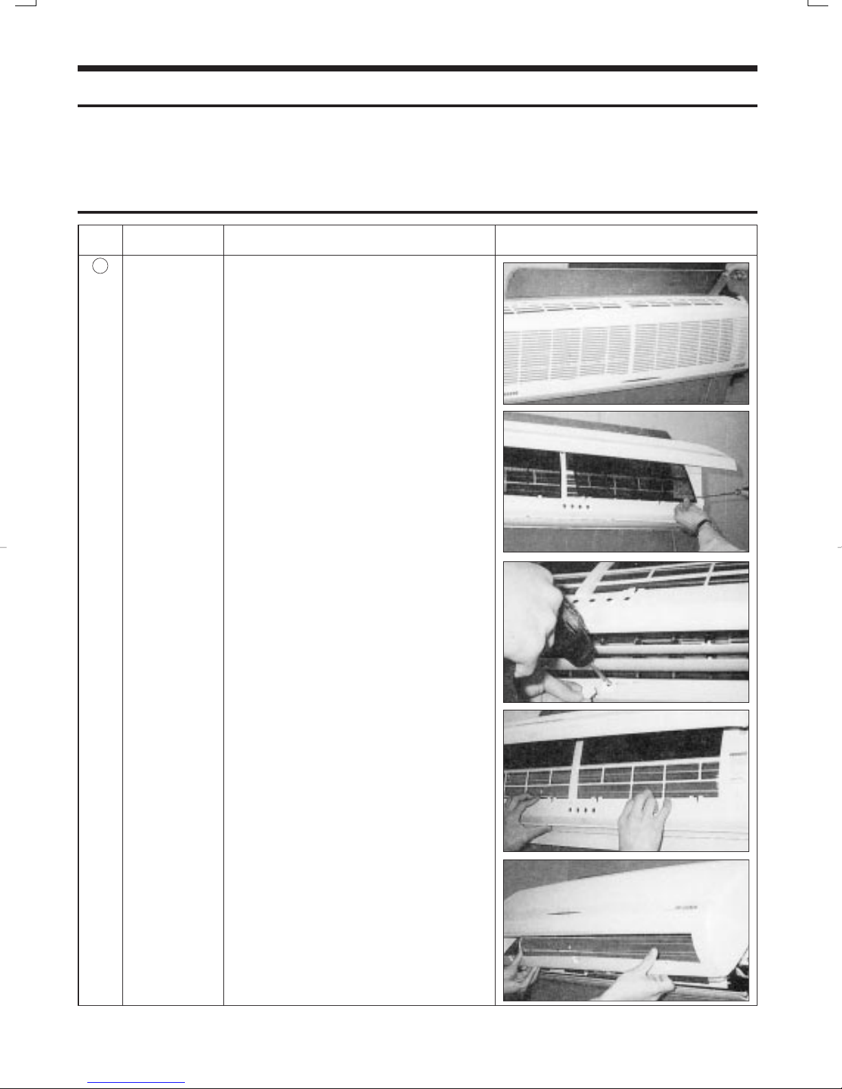
2-1 Indoor Unit
No Parts Procedure Remark
1
Front Grille 1) Stop the air conditioner operation and block the
main power.
2) Seperate the tape of front.
Panel upper.
3) Contract the second finger to the left and right
handle and pull to open the inlet grille.
4) Take the left and right filter out.
5) Loosen one of the right fixing screw and seperate the terminal cover.
6) Open the cover screw and loosen three fixing
screws of front grille.
7) Pull the upper left and right of discharge softly
for the outside cover to be pulled out.
8) Pull softly the lower part of discharge and push
it up
Caution:
Assemble the front panel and fix the hooks of
left and right.
3
No Parts Procedure Remark
2
3
Filter Frame
Ass'y Tray Drain
1) Loosen the left and right screw of the Holder
Filter, and Separate the Holder Filter.
1) Do , above.
1 2
Separate the holder at the rear side of Indoor
unit.
2) Take the display PCB out.
(Center of indoor unit).
3) Loosen three fixing screws of left and right.
4) Pull tray drain out from the back body.
4
Main PCB
1) Do " ", above
2) Take all the connector of PCB upper side out.
(Inclusion Power cord)
3) Separate the outdoor unit connection wire from
the terminal block.
4) If pulling the Main PCB up, it will be taken out.
(Separate the TRANS hook, it before).
4
1 2
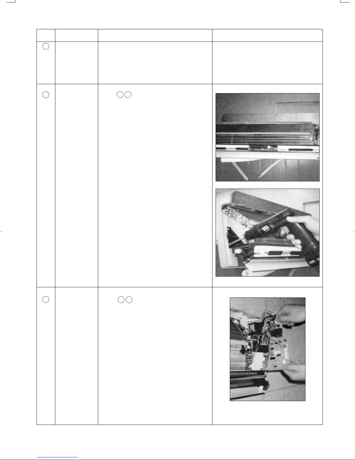
No Parts Procedure Remark
5
Heat Exchanger
1) Do " ", above.
1 2 3 4
2) Loosen the left screws of the heat exchanger.
Lifting the heat exchanger up a little to
push the up side for separation from the
indoor unit
6
Fan Motor and
Cross Fan
1) Do " ", above.
1 2 3 4 5
2) Loosen the fixing two screws and separate the
motor holder.
3) Loosen the fixing screw of motor fan.
(By use of M3 wrench)
Separate the motor from the fan.
Separate the fan motor the left holder bearing.
5
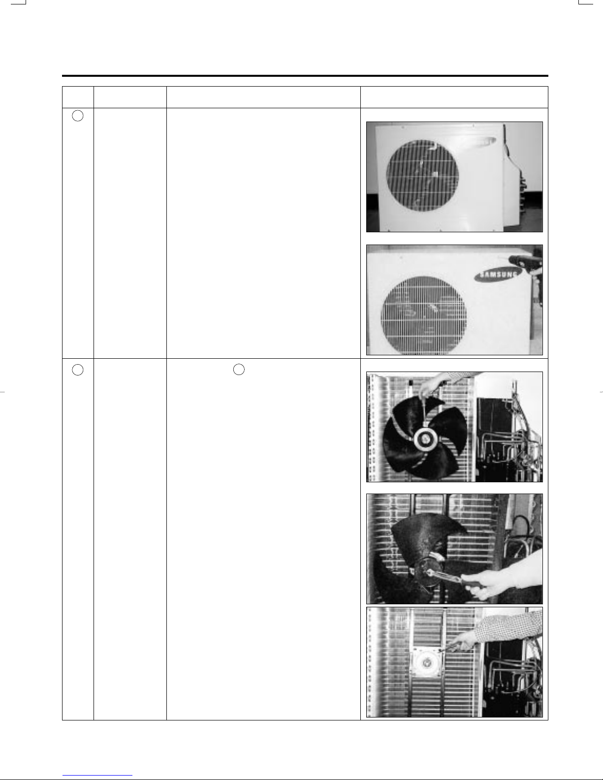
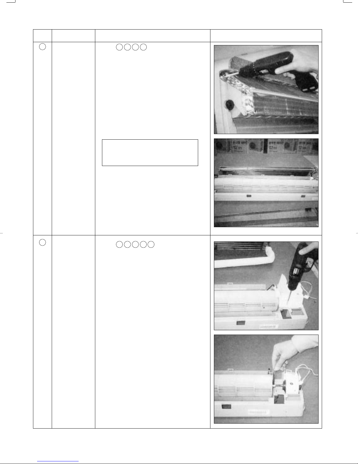
2-2 Outdoor Unit
No Parts Procedure Remark
1
2
Cabinet
Fan Motor &
Propeller Fan
1) Turn off the unit and remove the power cable
2) Remove the top cover.
3) Remove the control box cover.
4) Unplug the ass'y cable.
5) Remove the cabi-side.
6) Remove the cabi-front.
* When you assemble the parts, check if the
each parts and electric connectors are fixed
firmly.
1) Do Procedure above.
2) Remove the nut flange.
(Turn to the right to remove as it is a left turned
screw)
3) Disassemble the propeller fan.
1
<UD26A1C2>
<UD18A1C2>
<UD26A1C2>
6
<UD18A1C2>

3. Troubleshooting
3-1 Items to be checked first
1) Is the voltage of the power correct?
The input voltage shall be the rating Voltage ±10% range.
The airconditioner may not operate properly if the voltage is out of this range.
2) Is the link cable linking the indoor unit and the outdoor unit linked properly?
The indoor unit and the outdoor unit shall be linked by 4 cables.
Check the terminals if the indoor unit and outdoor unit are properly linked by the same number of
cables.
Otherwise the airconditioner may not operate properly.
3) When a problem occurs due to the contents illustrated in the table below it is a symptom not related to the malfunction of the airconditioner.
NO
1 The COOL operation indication LED (Green) blinks for 3minutes
when a power plug of the outdoor unit is plugged in for the first
time.
2 In a COOL operation mode, the compressor does not operate at a
room temperature lower than the setting temperature.
In a HEAT operation mode, the compressor does not operate at a
room temperature higher than the setting temperature.
3 Fan speed setting is not allowed in AUTO or DRY mode.
4 Compressor stops operation intermittently in DRY mode.
5 Compressor of the outdoor unit is operating although the indoor
unit is turned off in a HEAT mode.
6 Timer LED only of the indoor unit lights up and the
air conditioner does not operate.
7 The compressor and indoor fan stop intermittently in HEAT
mode.
8 Indoor fan and outdoor fan stop operation intermittently in
a HEAT mode.
9 The compressor stops intermittently in a COOL mode or DRY
mode, and fan speed of the indoor unit decreases.
Operation of air conditioner
It indicates power is on. The LED stops blinking if the operation ON/OFF
button on the remote control unit is pushed.
The speed of the indoor fan is set to LL in DRY mode.
Fan speed is 5 steps is selected automatically in AUTO mode.
Compressor operation is controlled automatically in DRY mode depending on the room temperature and humidity.
When the unit is turned off while de-ice is activated, the compressor
continues operation for up to 12 minutes (maximum) until the deice is
completed.
Timer is being activated and the unit is in ready mode.
The unit operates normally if the timer operation is cancelled.
The compressor and indoor fan stop intermittently if room temperature
exceeds a setting temperature in order to protect the compressor from
being overheated in a HEAT mode.
The compressor operates in a reverse cycle to remove exterior ice in a
HEAT mode, and indoor fan and outdoor fan do not operate intermittently
for within 20% of the total heater operation
The compressor stops intermittently or the fan speed of the indoor unit
decreases to prevent indoor heat exchanger from being frozen.
Explanation
4) Indoor unit observes operation condition of the air conditioner, and displays self diagnosis details
on the display panel.
NO
Operating Timer Fan Turbo
1
(GREEN)
2
3
4
5
6
7
X
(GREEN)
X
X
(GREEN)
(GREEN)
Display
X
X
X
X
X
X
X
Self Diagnosis
Restore from power failure (input initial power)
X
Indoor unit Room sensor Error (open or short)
X
Indoor unit heat exchanger temperature sensor Error (open or short)
X
Indoor fan malfunctioning (for speed is below 450rpm)
X
In case that the communication between the indoor unit and outdoor unit is not made for 60 seconds
X
Outdoor sensor Error (open or short)
- Outdoor sensor
X
- Pipe sensor A, B
The malfunction ot 4way valve in heat mode operation.
: Lamp blinking X : Lamp OFF
7

3-2 Fault Diagnosis by Symptom
3-2-1 When the power voltage is not available
1) Inspection items
(1) Is the power voltage is normal? (the rating voltage ±10% range)
(2) Is the power cord is correctly connected and is the contact good?
(3) Does the sound ÒtingÓ come out with the operation lamp (green) flickering when the power is
applied?
If it is not flickering, do inspect and repair in accordance with the following inspection
sequence.
2) Inspection sequence
Apply the power
Is the operation lamp of
Y Y
No trouble
(normal)
indoor unit on when the
operation /stop button of
remote controller is
pressed?
N
Is the operation lamp flickering with the
sound of ÒtingÓ?
N
Check of remote
controller
Normal
Is the communication sig-
N
nal of remote controller
surely sent and received ?
Is there no problem
Y
between the connector
of AssÕy display PCB and
the receiving module?
Replace of Ass'y display
PCB
N
Is the outdoor power connected normally?
Y
Is the fuse (F701, 250V, 3.15A) of PCB open?
N
Is the voltage at Socondery side of transformer
of PCB (TN71)? (AC15V~AC25V)
Is the output voltage of voltage regulator IC
(KA 7812) DC 10V and 12V?
Is the output voltage of electrostatic voltage
regulator IC (KA 7805) DC 4.5 V - 5.5 V?
Replace the main PCB of indoor unit
Y
N
Y
Y
Y
Check of the installation method and
electrical circuit
Y
Replace the fuse (250V, 3.15 A).
N
Transformer is out of order - replace
Repair and replace the power source
N
rectifying diode (D101- D105) and
KA7812.
N
KA7805 is out of order - replace
8
3-2-2 No Power (Outdoor unit)
1) Inspection items
(1) Is the power source normal (the rating voltage ±10% range)?
(2) Is the outdoor power connected normally? ((1) of terminal : L, (2) of terminal : N, (3) of terminal
: communication) ?
(3) Check whether the display of outdoor PCB(SEG1) is shown in the order of A- B - C when the
power is applied.
If the display (SEG 1) is not shown the inspection and repair shall be performed in the sequence
of the following:
2) Inspection sequence
Check the communi-
cation of PCB and
Normal of out-
door PCB
Replace the
transformer
Measurement of resistance of
N N
Assemble the transformer in
Y Y
whether the LED 1
is continuously flick-
ering.
N
Replace the fuse (F701)
250V 3.15A.
power transformer
Are they as follows?
1st side 190 ~ 210½
2nd side 0.9 ~ 1.1½
Y
the normal way.
Put the power off and put it on after 5 sec-
Is the display of PCB shown in the sequence
Are the power cord ((1) L, (2) N) and commu-
nication line (3) of outdoor terminal block con-
Is the terminal of PCB terminal (RY71, 72, 73)
are assembled in the correct position?
Y
Insert the primary side of power transformer
in the terminal GT01 and then is the voltage
of secondary side normal? (AC 15V- AC 25V)
Is the fuse (F101, 250V 2 A) blown out?
Check whether the output voltage of IC01 (KA
Check whether the output voltage of IC02 (KA
onds.
of A-B-C?
N
nected correctly?
Y
Y
Is the fuse open? (F701)
N
Y
N
7812) is DC 12V.
Y
7805) is DC 5V.
Y
Reinstall the power cord and
N
communication line with the ref-
erence of installation manual.
After watching the display of
N
PCB board, assemble the color
and shape of housing correctly
as follows:
BLK
WHT
RED
Y
Replace the fuse F101 (250V 2 A).
Check and Replace the rectifying
N
diode of power side (D101 -
D104) and KA 7812.
N
Replace the IC 02 (KA7805)
BLK
WHT
RED
Replace the outdoor unit Ass'y main PCB.
9
 Loading...