

Samsung UA32C5000QF, UA37C5000QF Schematic
LED-TV
Chassis : N92A
Model : UA32C5000QF
UA37C5000QF
UA40C5000QF
UA46C5000QF
UA32C4000PD
Manual
SERVICE
TFT-LCD TV Contents
1. Precautions
2. Product specications
3. Disassembly and Reassembly
4. Troubleshooting
5. Exploded View & Part List
6. Wiring Diagram
UA40C5000QF
Refer to the service manual in the GSPN (see the rear cover) for the more information.

Contents
1. Precautions .............................................................................................................. 1-1
1-1. Safety Precautions ......................................................................................................... 1-1
1-2. Servicing Precautions ..................................................................................................... 1-2
1-3. Electrostatically Sensitive Devices (ESD) Precautions .................................................. 1-2
1-4. Installation Precautions .................................................................................................. 1-3
2. Product specications ............................................................................................ 2-1
2-1. Feature & Specications ................................................................................................. 2-1
2-2. Detail Factory Option ...................................................................................................... 2-6
2-3. Accessories .................................................................................................................... 2-9
2-4. New Features explanation ............................................................................................ 2-10
3. Disassembly and Reassembly ............................................................................... 3-1
3-1. Disassembly and Reassembly ....................................................................................... 3-1
4. Troubleshooting ...................................................................................................... 4-1
4-1. Troubleshooting .............................................................................................................. 4-1
4-2. Alignments and Adjustments ........................................................................................ 4-25
4-3. Factory Mode Adjustments ........................................................................................... 4-26
4-4. White Balance - Calibration .......................................................................................... 4-34
4-5. White Ratio (Balance) Adjustment ................................................................................4-34
4-6. Servicing Information .................................................................................................... 4-35
4-7. How To Upgrade Sub Micom With Ddc Manager .........................................................4-36
4-8. PCB diagram ................................................................................................................ 4-38
5. Exploded View & Part List ...................................................................................... 5-1
5-1. UA32C5000QF Exploded View ...................................................................................... 5-1
5-2. UA32C5000QF Parts List ............................................................................................... 5-3
5-3. UA37C5000QF Exploded View ...................................................................................... 5-9
5-4. UA37C5000QF Parts List ............................................................................................. 5-11
5-5. UA40C5000QF Exploded View .................................................................................... 5-17
5-6. UA40C5000QF Parts List ............................................................................................. 5-19
5-7. UA46C5000QF Exploded View .................................................................................... 5-25
5-8. UA46C5000QF Parts List ............................................................................................. 5-27
5-9. UA32C4000PD Exploded View .................................................................................... 5-35
5-10. UA32C4000PD Parts List ........................................................................................... 5-37
6. Wiring Diagram ........................................................................................................ 6-1
6-1. Wiring Diagram ............................................................................................................... 6-1
6-2. Connector ....................................................................................................................... 6-3
6-3. Connector Functions ...................................................................................................... 6-6
6-4. Cables ............................................................................................................................ 6-6
GSPN (Global Service Partner Network)
Area Web Site
North America http://service.samsungportal.com
Latin America http://latin.samsungportal.com
CIS http://cis.samsungportal.com
Europe http://europe.samsungportal.com
China http://china.samsungportal.com
Asia http://asia.samsungportal.com
Mideast & Africa http://mea.samsungportal.com
This Service Manual is a property of Samsung Electronics Co.,Ltd.
Any unauthorized use of Manual can be punished under applicable
International and/or domestic law.
© 2010 Samsung Electronics Co.,Ltd.
All rights reserved.
Printed in Korea
P/N: BN82-00857A-00
3. Disassembly and Reassembly
3. Disassembly and Reassembly
This section of the service manual describes the disassembly and reassembly procedures for the UA37C5000Q LED TV.
WARNING: This LED TV contains electrostatically sensitive devices. Use caution when handling these components.
3-1. Disassembly and Reassembly
Cautions: 1. Disconnect the LED TV from the power source before disassembly.
2. Follow these directions carefully; never use metal instruments to pry apart the cabinet.
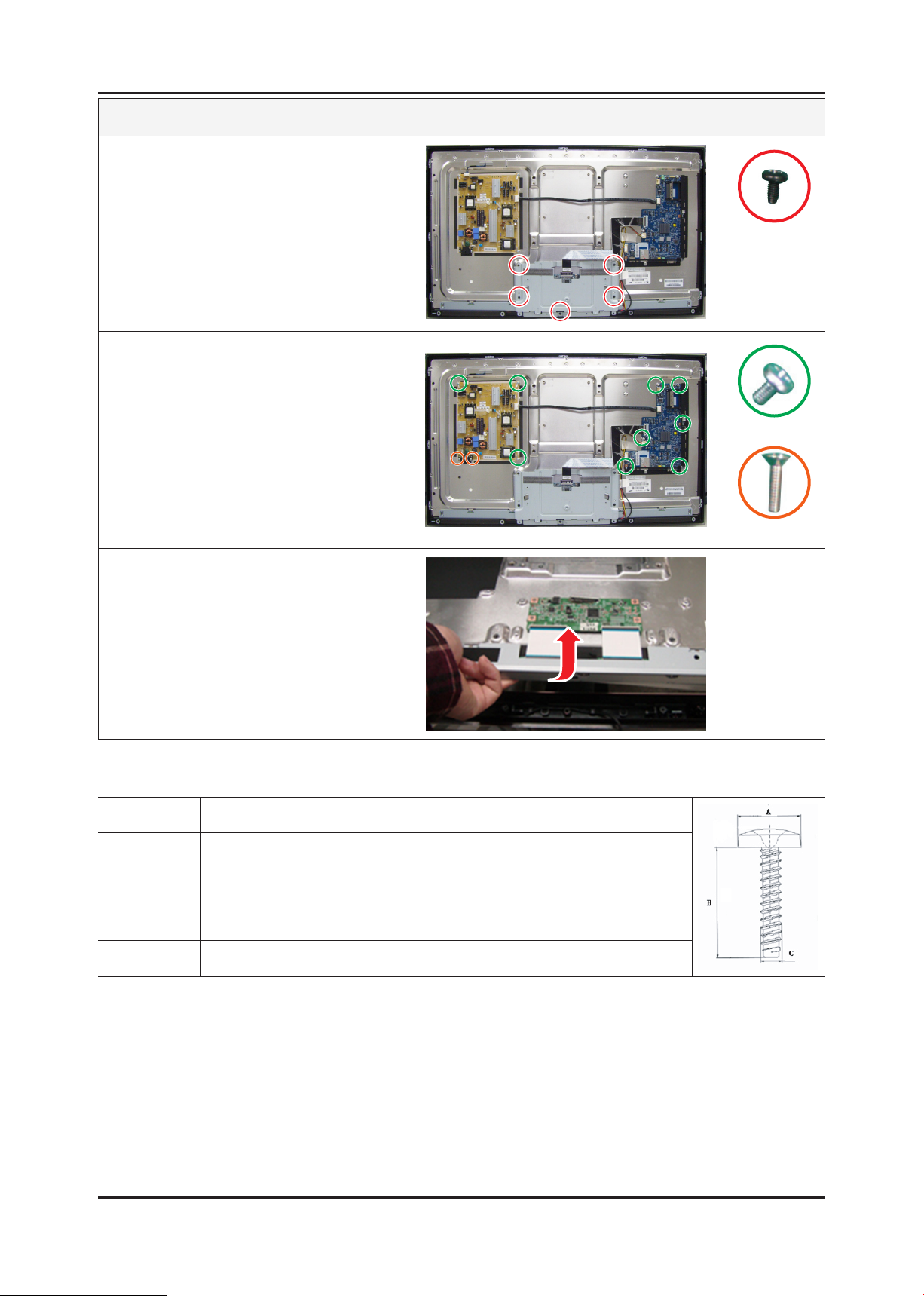
Description Picture Description Screws
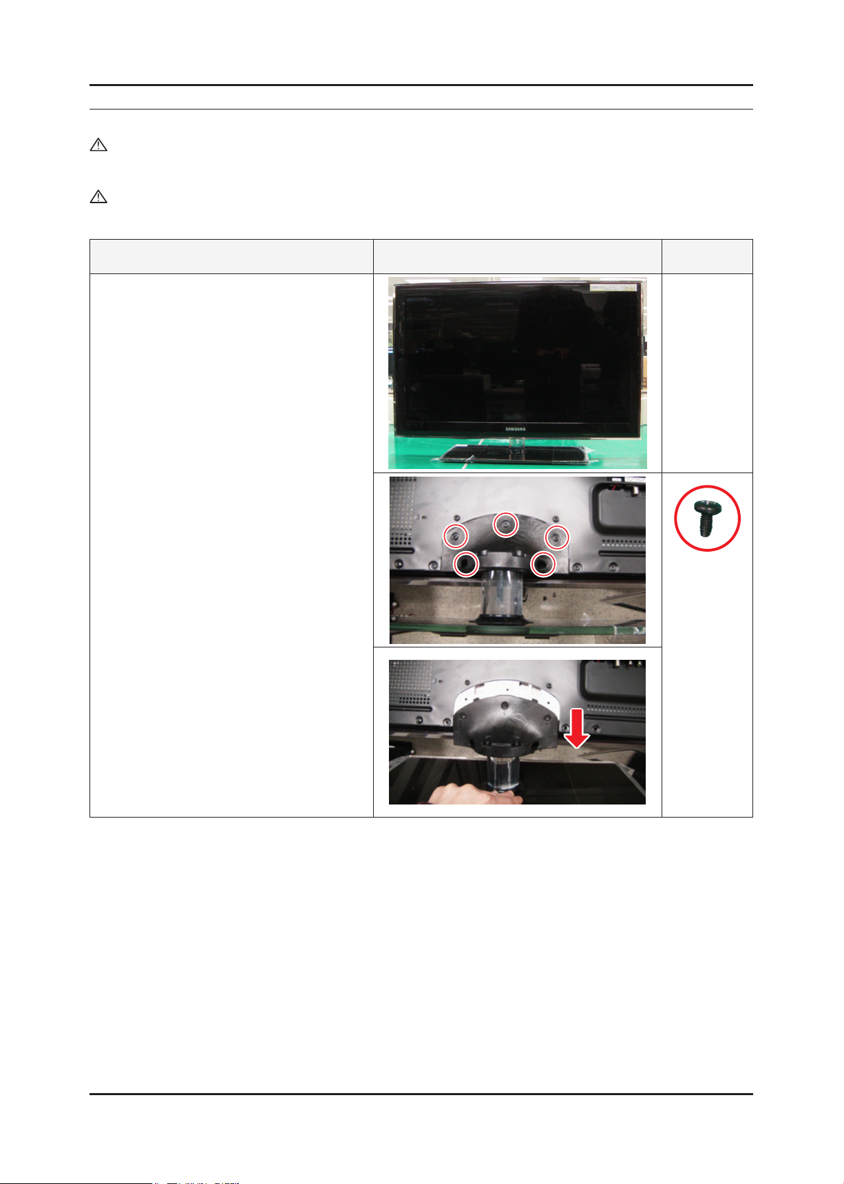
1. To remove the stand.
Place monitor face down on cushioned table.
Remove 5 screws from the stand.
Remove stand.
6003-000133
3-1
3-2
3. Disassembly and Reassembly
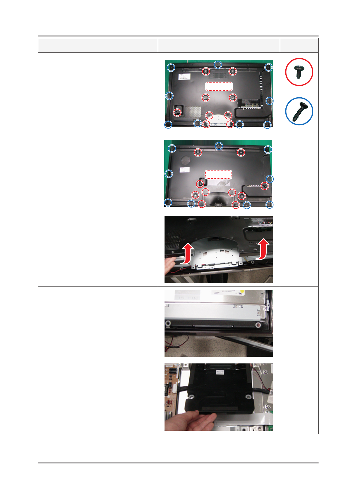
Description Picture Description Screws
2. 32"/37" C5000 :
Remove the 18 screws of rear-cover.
40"/46" C5000 :
Remove the 19 screws of rear-cover.
Remove the screws of rear-cover.
32"_37"
6003-000133
6003-001003
40"_46"
3. Lift up the rear-cover.
4. Remove the speaker and Wooper.
3-3
3. Disassembly and Reassembly
Description Picture Description Screws
5. Lift up the stand link.
Remove the 5 screws of bracket stand link.
6. Remove the 6 screws of main board and
5 screws of IP board.
6003-00133
6001-002283
7. Lift up the panel.
Reassembly procedures are in the reverse order of disassembly procedures. ※
Screw Size
Code No. A (mm) B (mm) C (mm) Q’ty
6003-001003 8.3~8.4 12~ 12.4 4~4.15 ALL : 9EA
6003-000133 8.3~8.4 7.9~8.3 3.70~3.83 32"/37" : 19EA , 40"/46" : 20EA
6001-002283 6.3~6.5 5.0~5.6 2.87~2.98 ALL : 9EA
6001-000115 5.8~6.3 9.4~10.0 2.87~2.98 ALL : 2EA
6001-000115
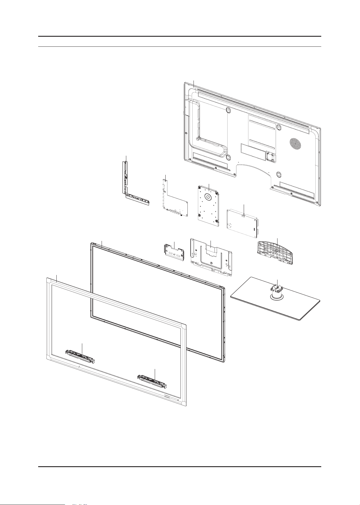
5. Exploded View & Part List
CB01
M0014
F001A
PANEL
T0910
R001A
T0175
M0027
SC02A
SP01A
SP01A
P001A
TCON
5-1. UA40C5000QF Exploded View
5. Exploded View & Part List
5-1

5-2
5. Exploded View & Part List
5-1-1. UA40C5000QF Parts List
Location No. Code No. Description & Specication Q’ty S.A/S.N.A Remark
CB01 BN61-04924F BRACKET-AV;UC5000,PCM,T0.5,BKN-P824 , TA 1 SNA
F001A BN96-12891D ASSY COVER P-FRONT;UC5000 40,PMMA(CLR)+P 1 SA
M0014 BN94-02648C ASSY PCB MAIN;UA40C5000QFXXY 1 SA
M0027 BN96-12762A ASSY STAND P-BASE;37,40,EXPORT,TEMPERED 1 SA
P001A BN44-00353A SMPS-LED TV PD BD;PD46AF0E_ZSM,PSLF121BO 1 SA
PANEL BN07-00856A LCD-PANEL;T400FAE1-DB,CLL6BC1,8bits,40,1 1 SA
R001A BN96-12914F ASSY COVER P-REAR;UC5000 40,AUSTRALIA,PC 1 SA
SC02A BN96-13131E ASSY COVER P-GUIDE STAND;UC7000,PC+ABS G 1 SA
SP01A BN96-12941G ASSY SPEAKER P;8ohm,4pin,10,L:410 R:760, 1 SA
T0175 BN96-12965A ASSY SPEAKER P;4ohm,4pin,20W,R: 680,Encl 1 SA
T0910 BN96-12928A ASSY BRACKET P-STAND LINK;UC6500 40,SECC 1 SNA
TCON BN81-04455A A/S-T CON T400FAE1-DB;T400FAE1-DB 1 SA

5-3
5. Exploded View & Part List
5-2. UA40C5000QF Parts List
Service Bom (SA: SERVICE AVAILABLE, SNA: SERVICE NOT AVAILABLE)
Level Location No. Code No. Description & Specication Q’ty SA/SNA Remark
0.1 BN90-02530E ASSY COVER FRONT;UC5000 40 1 SNA
..2 F001A BN96-12891D ASSY COVER P-FRONT;UC5000 40,PMMA(CLR)+P 1 SA
...3 CCM1 BN63-02183G COVER-SHEET;Rhcm,PE Vinyl,T0.05,1100mm,2 0.65 SNA
...3 CCM1 BN63-05199B COVER-SHEET;AMBER,PE,T0.08,W65mm,200M,CL 3.3 SNA
...3 F001 BN63-06611D COVER-FRONT;UC5000 40,PMMA(CLR)+PMMA/ABS 1 SNA
...3 BN96-12921A ASSY HOLDER P-BOSS;UC6400 40,ABS V0,BK00 1 SNA
....4 BN61-04692A BOSS-PRIMER;#94,clear,35cps 0.001 SNA
....4 BN61-05915A BOSS-TAPE;LB650 65",T1.1,W12.0mm,DARK GR 0.43 SNA
....4 BN61-05915B BOSS-TAPE;LB650 65",3M #4711,T1.1,W6.0mm 0.03 SNA
....4 BN61-06238A HOLDER-BOSS BOTTOM;UC6100 40inch,ABS,HB 1 SNA
...3 T0382 BP61-00495C HOLDER-CARE;PJT,ACRYL-FOAM,T0.25,W30.0mm 0.16 SNA
...3 M0125 BN96-13047D ASSY BOARD P-TOUCH FUNCTION&IR;UC5000,CT 1 SA
...3 BN60-00162Y SPACER-FOAM;FOAM,50000mm,Dark Gray,0.35T 1.76 SA
...3 BN61-06630A BOSS-BOND;UC5000,Acrylated, 3276,Clear,A 1 SNA
...3 AB326 BN61-04661A BRACKET-STOPPER;L650,SK-5,T0.4,Plating,H 3 SNA
...3 BN61-06213A BRACKET-STOPPER BOSS;C8K,SECC+SK5,T1.2 8 SNA
...3 BN61-06215A BRACKET-STOPPER PANEL;C8K,SK5,0.5T 1 SNA
...3 SP01A BN96-12941G ASSY SPEAKER P;8ohm,4pin,10,L:410 R:760, 1 SA
...3 CIS1 0203-001598 TAPE-FILAMENT;#8915,0.15,12,55000,CLR 0.06 SNA
...3 BN61-05728A BOSS-TAPE;UB7000,T0.4,W10,DARK GRAY 1 SNA
0.1 R001A BN90-02552D ASSY COVER REAR;UC5000 40 1 SNA
..2 R001A BN96-12914F ASSY COVER P-REAR;UC5000 40,AUSTRALIA,PC 1 SA
...3 BN68-02543C LABEL-TERMINAL BOTTOM;Rev.02 UC5000,PET, 1 SNA
...3 BN68-02544C LABEL-TERMINAL SIDE;Rev.01 UC5000/6000,X 1 SNA
...3 R001 BN63-06518D COVER-REAR;UC6500 40inch,PCM,T0.5,BKN-P8 1 SNA
...3 BN96-12924B ASSY MISC P-INSULATOR;UC6500 37/40,PC,T0 1 SNA
....4 T0278 BN60-00122E SPACER-SPONGE;UC6500,CR,L200,T2.0,W10 2 SNA
....4 BN63-06630A SHEET-INSULATOR SMPS;UC6100 40inch,PC,T0 1 SNA
...3 T0069 AA63-60131R SPACER-FELT;21Z57,FELT,325,T0.35,7 1 SNA
...3 BN60-00162A SPACER-FOAM;FOAM,50000L,BLK,0.35T,20W 0.92 SNA
...3 BN60-00162Y SPACER-FOAM;FOAM,50000mm,Dark Gray,0.35T 0.8 SA
..2 T0081 6001-002610 SCREW-MACHINE;BH,+,M4,L6,ZPC(BLK),SWRCH1 8 SA
..2 SCREW 6003-001782 SCREW-TAPTYPE;BH,+,B,M4,L12,ZPC(BLK),SWR 11 SA
0.1 BN91-05201A ASSY LCD;BN07-00856A 1 SNA
..2 PANEL BN07-00856A LCD-PANEL;T400FAE1-DB,CLL6BC1,8bits,40,1 1 SA
...3 TCON BN81-04455A A/S-T CON T400FAE1-DB;T400FAE1-DB 1 SA
0.1 BN91-05204A ASSY SHIELD;UA40C5000QFXXY 1 SNA
..2 T0081 6001-000115 SCREW-MACHINE;BH,+,-,M3,L10,ZPC(WHT),SWR 2 SNA
..2 T0081 6001-002283 SCREW-MACHINE;BH,+,M3,L5,ZPC(WHT),SWRCH1 9 SNA
..2 P001A BN44-00353A SMPS-LED TV PD BD;PD46AF0E_ZSM,PSLF121BO 1 SA
...3 BN81-04725A A/S-DIODE;600V, 3A,DD407,DD807 1 SNA
...3 BN81-04726A A/S-DIODE;600V, 4A,D9102, D9202 1 SNA
...3 BN81-04734A A/S-FUSE;250V, 6.3A,FS801S, FS802S 2 SNA
...3 BN81-04741A A/S-MOSFET;400V, 1.2A,QD407 1 SNA
...3 BN81-04747A A/S-MOSFET;500V, 5A,Q9105,QD807,Q9106 1 SNA
...3 BN81-04753A A/S-MOSFET;600V, 7.5A,QP801 1 SNA
...3 BN81-04754A A/S-MOSFET;600V, 9.5A,QP801, QP802 2 SNA
...3 BN81-04773A A/S-PWM CONTROL IC;650V, 0.65#,ICB801 1 SNA

5-4
5. Exploded View & Part List
Level Location No. Code No. Description & Specication Q’ty SA/SNA Remark
...3 BN81-04774A A/S-PWM CONTROL IC;650V, 1.7#,ICB801 1 SNA
..2 T0910 BN96-12928A ASSY BRACKET P-STAND LINK;UC6500 40,SECC 1 SNA
...3 M0115 BN61-06165A BRACKET-STAND LINK;UC6500 40inch,SECC,T2 1 SNA
...3 BN61-02932G BRACKET-STOPPER NUT;LED TV,M4,D6,L6.5,BR 5 SNA
...3 BN60-00184A SPACER-FOAM;FOAM,30000mm,DARK GRAY,1T,30 0.18 SNA
..2 T0175 BN96-12965A ASSY SPEAKER P;4ohm,4pin,20W,R: 680,Encl 1 SA
..2 M2893 BN39-01267C LEAD CONNECTOR;LE37B530,UL 2651 AWG#26,1 1 SA
..2 FL06 BN96-13171R ASSY CABLE P-FFC;UE40C5100,FFC,0.5mm,489 1 SA
..2 T0081 6001-002610 SCREW-MACHINE;BH,+,M4,L6,ZPC(BLK),SWRCH1 4 SA
..2 SCREW 6003-001782 SCREW-TAPTYPE;BH,+,B,M4,L12,ZPC(BLK),SWR 1 SA
..2 CIS1 0203-001586 TAPE-FILAMENT;#893,0.15,25,55 0.15 SNA
..2 CCMM1 BN73-00211B SILICON/RUBBER;UN46B9000XFXZA,SILICON+PO 1 SNA
..2 M0131 BN63-00209A GASKET;RS24NS,CONDUCTIVE FAB,4mm,10mm,30 3 SNA
0.1 BN92-05579E ASSY BOX;UC5000 40 1 SNA
..2 BN69-04765E BOX-SET;40UC5000-GS,CB,A-01,DW2,,W1185,D 1 SNA
..2 BH68-00662A LABEL BOX-00;ALL MODEL,MOJO 90G,60,110,W 1 SNA
0.1 BN92-05601A ASSY P/MATERIAL;UC5000 40 1 SNA
..2 T0214 0203-001595 TAPE-OPP MASKING;OPP-2,0.075,75,800M,CLR 2.68 SNA
..2 6902-000061 BAG AIR;LDPE,T0.2,W500,L1000,TRP,370.000 1 SNA
..2 6902-000379 BAG AIR;LDPE,T0.2,W1000,L1800,TRP,1260.0 1 SNA
..2 6902-000604 BAG WRAPPING;LDPE,T0.02,W500,L10000,TRP, 3.81 SNA
..2 6902-000609 BAG ROLL;LDPE,T0.05,W2400,L1000,TRP,30.0 0.07 SNA
..2 T0524 6902-001043 BAG PE;HDPE/NITRON,T0.015/T0.5,W1200,L80 1 SNA
..2 M040 6922-000013 BAND PP;PP,W18,L2300m,TRP,21000g 1.05 SNA
..2 BN69-00391P PAD-ANGLE;OTHER,T4,50,2200,YEL 1 SNA
..2 T0246 BN69-04593A CUSHION-SET;UC5000 40inch,EPS,M65 1 SNA
..2 BN68-02422B LABEL-WARNING SHIPPING;ALL MODEL,A/P 100 1 SNA
0.1 ACCE1 BN92-05880B ASSY ACCESSORY;UA40C5000QFXXY 1 SNA
..2 BN96-13393A ASSY ACCESSORY-MANUAL;UA32C5000QFXXY 1 SNA
...3 PE BAG 6902-000009 BAG PE;HDPE,T0.03,W240,L400,TRP,8,2,-,5. 1 SNA
...3 AA68-03242M MANUAL FLYER-MANUAL FLYER-06,SAFETY GUID 1 SNA
...3 T0527 BH68-20009B LABEL-ACCESSORY;ART-PAPER 100G,15,100,SD 1 SNA
...3 BN68-02186A MANUAL FLYER-TOC GUIDE;COMM,SAMSUNG,11 L 1 SNA
...3 BN68-02727A MANUAL USERS-IB;Comm,Samsung,English,Asi 1 SNA
...3 BP68-00274E MANUAL FLYER-WARRANTY CARD;comm,Samsung, 1 SNA
..2 ACCE2 BN96-13393C ASSY ACCESSORY-CABEL;UA40C5000QFXXY 1 SNA
...3 T0685 4301-000103 BATTERY-ALKALINE;1.5V,750mAH,LR03,10.5x4 2 SNA
...3 T0524 6902-001107 BAG PE;LDPE,T0.05,W450,L400,TRP,0,3Separ 1 SNA
...3 T0527 BH68-20009B LABEL-ACCESSORY;ART-PAPER 100G,15,100,SD 1 SNA
...3 M0114 BN39-01154B CBF SIGNAL;Chelsea Slim,24P/RCA3P,30AWG, 1 SA
...3 M0114 BN39-01154C CBF SIGNAL;Chelsea Slim, STEREO Plug to 1 SA
...3 M0114 BN39-01154D CBF SIGNAL;Chelsea Slim, STEREO Plug to 1 SA
...3 REMO2 BN59-01015A REMOCON;TM1060,SAMSUNG,20PIN SINGLE,49KE 1 SA
...3 BN61-05596A HOLDER-WIRE CABLE;LED TV,LDPE,T0.8,L150, 1 SNA
...3 M9889 BN63-01798B CLOTH-CLEAN;cloth,180,200,sea blue,ToC 1 SA
...3 T0531 BN63-06543A COVER-BOTTOM;UC6500 40inch,HIPS,HB,BLK 1 SA
...3 EH03A BN96-10276B ASSY HOLDER P-RING;09 LEDTV ALL MODEL,AB 1 SA
....4 6902-000683 BAG ZIPPER;LDPE,T0.05,W60,L60,TRP,4-PE M 1 SNA
....4 AH365 BN61-05280A HOLDER-RING;LB7000 46inch,ABS, HB,gray 4 SNA
...3 EH02A BN96-10810A ASSY HOLDER P;09 LEDTV MODEL,NYRON 1 SA
....4 BAG 6902-000031 BAG ZIPPER;LDPE,T0.05,W80,L160,TRP,0,0,4 1 SNA

5-5
5. Exploded View & Part List
Level Location No. Code No. Description & Specication Q’ty SA/SNA Remark
....4 M0114 BN61-05373A HOLDER-WIRE;LB7000 46,NYRON 3 SNA
....4 BN61-05491A HOLDER-WIRE STAND;UB7000 46inch,NYRON 1 SNA
...3 BN96-12031D ASSY ACCESSORY-SCREW;09 LEDTV(40/46/55), 1 SNA
....4 M0081 6003-000133 SCREW-TAPTYPE;BH,+,-,S,M4,L8,ZPC(BLK),SW 1 SA
....4 BN69-04419E PACKING-BAG PE;LB650,LDPE,70,90,6003-000 1 SNA
...3 BN96-14099A ASSY ACCESSORY-CLAMP;10 LEDTV(40/46/55), 1 SNA
....4 AA65-30023A CLAMPER CORE-CABLE;NYLON-66,BLK 1 SNA
....4 BN69-04419J PACKING-BAG PE;UC5000,LDPE,70,90,Power-C 1 SNA
...3 EC11 3903-000563 CBF-POWER CORD;DT,AU,LP-15AL,N,250V,7.5A 1 SA
0.1 BN92-05883B ASSY LABEL;UA40C5000QFXXY 1 SNA
..2 T0527 AA68-03752B LABEL-STICKER;WW,ALL,Art Paper(90g),25,3 1 SNA
..2 BN68-02700A LABEL-LED-POP;Highlight Sticker Color,PE 1 SNA
..2 T0527 BP68-00052B LABEL-00,RATING;CCTV,TETRON PAPER,T0.05, 1 SNA
..2 BN68-02894H LABEL-STICKER;UC5R,XY,T0.05,70,115,Energ 1 SNA
0.1 S001A BN90-02558D ASSY STAND;UC5000 37 1 SNA
..2 SC02A BN96-13131E ASSY COVER P-GUIDE STAND;UC7000,PC+ABS G 1 SA
...3 T0524 6902-001063 BAG PE;LDPE,T0.05,W180,L350,TRP,RECYCLE 1 SNA
...3 T0920 BN61-06221A GUIDE-STAND;UC6500 40inch,PC,G/F 20%,V2, 1 SNA
...3 BN68-02824B MANUAL FLYER-01,STAND GUIDE;5 ~ 6 series 1 SNA
...3 BN96-12031C ASSY ACCESSORY-SCREW;09 LEDTV,6003-00013 1 SNA
....4 M0081 6003-000133 SCREW-TAPTYPE;BH,+,-,S,M4,L8,ZPC(BLK),SW 5 SA
....4 BN69-04419D PACKING-BAG PE;LB650,LDPE,70,90,6003-000 1 SNA
...3 BN96-12031M ASSY ACCESSORY-SCREW;10 LEDTV(40/46/55), 1 SNA
....4 M0081 6003-001003 SCREW-TAPTYPE;BH,+,B,M4,L12,ZPC(BLK),SWR 5 SA
....4 BN69-04419K PACKING-BAG PE;UC5000,LDPE,70,90,4X12, 5 1 SNA
..2 M0027 BN96-12762A ASSY STAND P-BASE;37,40,EXPORT,TEMPERED 1 SA
...3 M0081 6003-001003 SCREW-TAPTYPE;BH,+,B,M4,L12,ZPC(BLK),SWR 6 SA
...3 BN61-04692A BOSS-PRIMER;#94,clear,35cps 0.1 SNA
...3 BN61-04731D BOSS-TAPE;AMBER,ACRYL,T1.1,W20.0mm,WHITE 0.29 SNA
...3 BN61-05244A BRACKET-SWIVEL BOTTOM;LB700 46,HGI,T3.0 1 SNA
...3 BN61-05493A HOLDER-SWIVEL RING BOTTOM;LB650 40,Aceta 1 SNA
...3 BN61-05652A BRACKET-STAND BOTTOM;B650 40,SECC,T2.0 1 SNA
...3 BN61-05826A BOSS-BOND;#760,Poly urethane,Black 2.6 SNA
...3 GSN01 BN61-05994A GUIDE-STAND NECK;40,LC650,PETG,V2,TP0003 1 SNA
....4 BN61-06079B GUIDE-NECK-INSERT;LC650 40,PETG HB,TP000 1 SNA
...3 CCM1 BN63-04755A COVER-SHEET;AMBER,PE,T0.05,W150mm,200M,6 1.14 SNA
...3 BN63-05781D COVER-STAND GLASS;40,LC650,GLASS,T8.0,2C 1 SNA
...3 T0527 BN68-01648B LABEL WARNING;WW,PET,T0.05,40,25,EXPORT 1 SNA
...3 M0126 BN73-00215A RUBBER-FOOT;40LB650,RUBBER,15*25,60,4.0, 4 SNA
...3 M0126 BN73-00217A RUBBER-FOOT;LB650,RUBBER,DIA30,7.5,Dark 4 SNA
...3 BN74-00031A GREASE;kanto-kasei FL-955,grease,wht 0.4 SNA
...3 FD01 BN63-06913A COVER-DECORATION;LB7000 46,ABS+PMMA,HB,H 1 SNA
0.1 M0017 BN91-05206C ASSY CHASSIS;UA40C5000QFXXY 1 SNA
..2 M0014 BN94-02648C ASSY PCB MAIN;UA40C5000QFXXY 1 SA
...3 0202-001521 SOLDER-WIRE FLUX;ECO SOLDER RMA98 SUP,D1 0.25 SNA
...3 3701-001698 CONNECTOR-DSUB;15P,3ROW,FEMALE,ANGLE,NI 1 SA
...3 3711-007302 HEADER-BOARD TO BOARD;BOX,18P,2R,2mm,ANG 1 SA
...3 JA330 3722-002844 JACK-PHONE;1/7P,NI,LAUREL-GREEN,ANGLE 1 SA
...3 JA330 3722-002845 JACK-PHONE;1/7P,NI,YELLOW,ANGLE 1 SA
...3 JA330 3722-002846 JACK-PHONE;1/6,NI,BLACK,ANGLE 2 SNA
...3 3722-002849 JACK-MODULAR;8P/8C(ULTRA SLIM),YES,ANGLE 1 SNA

5-6
5. Exploded View & Part List
Level Location No. Code No. Description & Specication Q’ty SA/SNA Remark
...3 ET01 BN40-00181A TUNER;TDAG4-K02A,TDAG4-K02A,PAL-B/G,163, 1 SA
...3 T0066 BN62-00042A HEAT SINK-ES;30*30*5,Ceramic,T1.5,TAPE 1 SNA
...3 T0527 BN68-00513A LABEL-E,PASS;ALL MODEL,YUPO(110G),50X15, 1 SNA
...3 BN97-04105C ASSY SMD;UE46C5100QFXXC,BN94-03368A 1 SNA
....4 0202-001767 SOLDER-CREAM;LST-5710,D20~38,Sn-57Bi-1Ag 2.072 SNA
....4 DS01A 0401-001056 DIODE-SWITCHING;MMBD4148SE,100V,200mA,SO 21 SA
....4 D0254 0402-000553 DIODE-SCHOTTKY;SS24/B240,40V,2000mA,DO-2 2 SA
....4 0403-001164 DIODE-ZENER;MMSZ5232B,5.32-5.88V,500MW,S 1 SA
....4 0403-001783 DIODE-ZENER;BZB84-C6V2,5.8/6.6V,300mW,SO 13 SNA
....4 D0254 0404-001404 DIODE-SCHOTTKY;BAT721C,40V,200mA,SOT-23, 1 SA
....4 T0139 0406-001200 DIODE-TVS;RCLAMP0504F,6/-/-V,150W,SC-70 2 SA
....4 T0139 0406-001271 DIODE-TVS;RCLAMP0524P,6/-/-V,150W,SLP251 9 SNA
....4 SD3 0407-000114 DIODE-SWITCHING;KDS184,80V,100mA,SOT-23, 3 SNA
....4 Q101 0501-000445 TR-SMALL SIGNAL;KTC3875S-Y,NPN,150mW,SOT 10 SA
....4 CEQ2 0505-000110 FET-SILICON;2N7002,N,60V,115mA,7.5ohm,0. 5 SA
....4 Q409 0505-000274 FET-SILICON;AO4435L,P,-30V,-11A,0.014ohm 1 SNA
....4 ND51C2 0801-002780 IC-CMOS LOGIC;74LVC1G17,SCHMITT-TRIGGER 1 SA
....4 T0596 0904-002554 IC-USC;AU6256-JBF,QFN,28P,5x5mm,12MHz,TP 1 SA
....4 IC106 1001-001573 IC-VIDEO SWITCH;SiI9287BCNUTR,QFN,72P,10 1 SNA
....4 1006-001474 IC-LINE DRIVER;DRV604PWP,HPSSOP,28P,9.8x 1 SA
....4 IC112 1103-000129 IC-EEPROM;24C02,2Kbit,256x8,SOP,8P,5x4mm 2 SA
....4 IC112 1103-001385 IC-EEPROM;AT24C256,256Kbit,32Kx8,SOP,8P, 1 SA
....4 1105-002058 IC-DDR2 SDRAM;K4T1G164QE-HCF8,DDR2,1Gbit 2 SA
....4 T0124 1201-002992 IC-POWER AMP;STA369BWS,PSSO,36P,10.3x7.5 2 SA
....4 T0087 1203-001815 IC-POSI.FIXED REG.;78M09,TO-252,3P,PLAST 1 SA
....4 T0087 1203-002835 IC-POSI.FIXED REG.;KIA7805AF,DPAK,3P,6.6 1 SA
....4 T0087 1203-002898 IC-POSI.FIXED REG.;G950T45R,T0-252,3P,6. 1 SA
....4 1203-004364 IC-VOL. DETECTOR;RT9818C-42PV,SOT-23,3P, 1 SA
....4 1203-005538 IC-DC/DC CONVERTER;AOZ1021HAIL,SOP,8P,4. 1 SA
....4 1203-005559 IC-BACKLIGHT DRIVER;MP3302DJ,TSOT23,5P,2 1 SA
....4 1203-006013 IC-DC/DC CONVERTER;AOZ1031AI,SO-8,8P,4.9 1 SA
....4 1203-006017 IC-VOL. DETECTOR;RT9824GJ8,TSOT23,8P,2.9 1 SA
....4 T0087 1203-006135 IC-POSI.FIXED REG.;AP1117D-33-GZ-13-89,T 1 SA
....4 T0087 1203-006136 IC-POSI.FIXED REG.;AP1117D-18-GZ-13-89,T 1 SA
....4 IC012 1203-006138 IC-POSI.ADJUST REG.;AP1117DGZ-13-89,TO-2 1 SA
....4 1203-006288 IC-VOL. DETECTOR;RT9818B-18GV,SOT-23-3,3 1 SA
....4 1204-003088 IC-DEMODULATOR;DRX39XYK,PQFN,64P,9x9x0.8 1 SA
....4 1204-003096 IC-VIDEO DECODER;HIDTVPRO-SX,PBGA,580P,P 1 SA
....4 1205-003201 IC-BUS SWITCH;TC7WB125FK,SSOP,8P,2x2.3mm 2 SA
....4 1205-003733 IC-SWITCH;AP2191MPG-13,MSOP-8L-EP,8P,2.9 1 SA
....4 1205-003735 IC-SWITCH;AP2151WG-7,SOT25,5P,2.9x1.6mm, 1 SA
....4 1405-001185 VARISTOR;24Vdc,1.6x0.8x0.36mm,TP 1 SA
....4 1405-001271 VARISTOR;20Vdc,5A,1.0x0.5x0.6mm,TP 21 SA
....4 PR6 2007-000072 R-CHIP;47ohm,5%,1/10W,TP,1608 6 SNA
....4 R105 2007-000138 R-CHIP;100ohm,5%,1/16W,TP,1005 26 SNA
....4 AR49 2007-000140 R-CHIP;1Kohm,5%,1/16W,TP,1005 5 SNA
....4 MR306 2007-000141 R-CHIP;2.2Kohm,5%,1/16W,TP,1005 14 SNA
....4 R319 2007-000143 R-CHIP;4.7Kohm,5%,1/16W,TP,1005 45 SNA
....4 2007-000146 R-CHIP;6.8Kohm,5%,1/16W,TP,1005 2 SNA
....4 R104 2007-000148 R-CHIP;10Kohm,5%,1/16W,TP,1005 41 SNA
....4 R102 2007-000149 R-CHIP;12Kohm,5%,1/16W,TP,1005 6 SA

5-7
5. Exploded View & Part List
Level Location No. Code No. Description & Specication Q’ty SA/SNA Remark
....4 MR36 2007-000153 R-CHIP;22Kohm,5%,1/16W,TP,1005 7 SNA
....4 AR43 2007-000155 R-CHIP;27Kohm,5%,1/16W,TP,1005 2 SNA
....4 MR13 2007-000157 R-CHIP;47Kohm,5%,1/16W,TP,1005 6 SNA
....4 R123 2007-000159 R-CHIP;56Kohm,5%,1/16W,TP,1005 3 SNA
....4 DR39 2007-000162 R-CHIP;100Kohm,5%,1/16W,TP,1005 2 SNA
....4 MR16 2007-000168 R-CHIP;470Kohm,5%,1/16W,TP,1005 1 SNA
....4 R509 2007-000170 R-CHIP;1Mohm,5%,1/16W,TP,1005 1 SNA
....4 R111 2007-000171 R-CHIP;0ohm,5%,1/16W,TP,1005 7 SNA
....4 HDR17 2007-000172 R-CHIP;10ohm,5%,1/16W,TP,1005 12 SNA
....4 R338 2007-000173 R-CHIP;22ohm,5%,1/16W,TP,1005 13 SNA
....4 UR23 2007-000174 R-CHIP;47ohm,5%,1/16W,TP,1005 2 SNA
....4 MR9 2007-000455 R-CHIP;18Kohm,1%,1/10W,TP,1608 1 SA
....4 ER13 2007-000669 R-CHIP;2Kohm,1%,1/10W,TP,1608 1 SNA
....4 R726 2007-000695 R-CHIP;3.3ohm,5%,1/10W,TP,1608 2 SNA
....4 2007-000755 R-CHIP;330Kohm,1%,1/10W,TP,1608 1 SA
....4 R124 2007-000775 R-CHIP;33Kohm,5%,1/16W,TP,1005 3 SNA
....4 2007-001285 R-CHIP;5.6ohm,5%,1/16W,TP,1005 4 SA
....4 OTR1 2007-001292 R-CHIP;33ohm,5%,1/16W,TP,1005 2 SNA
....4 R326 2007-001325 R-CHIP;3.3Kohm,5%,1/16W,TP,1005 11 SNA
....4 MR316 2007-002796 R-CHIP;510ohm,5%,1/16W,TP,1005 1 SA
....4 TR30 2007-007009 R-CHIP;75ohm,5%,1/16W,TP,1005 12 SA
....4 2007-007134 R-CHIP;39Kohm,1%,1/16W,TP,1005 1 SA
....4 2007-007135 R-CHIP;18Kohm,1%,1/16W,TP,1005 1 SNA
....4 DR4 2007-007142 R-CHIP;10Kohm,1%,1/16W,TP,1005 3 SNA
....4 2007-007156 R-CHIP;1ohm,5%,1/16W,TP,1005 9 SNA
....4 2007-007316 R-CHIP;3.3Kohm,1%,1/16W,TP,1005 1 SNA
....4 2007-007318 R-CHIP;1Kohm,1%,1/16W,TP,1005 10 SNA
....4 2007-007334 R-CHIP;200Kohm,1%,1/16W,TP,1005 4 SNA
....4 MR11 2007-008015 R-CHIP;75ohm,1%,1/16W,TP,1005 13 SNA
....4 2007-008134 R-CHIP;12.4Kohm,1%,1/16W,TP,1005 1 SC
....4 2007-008298 R-CHIP;49.9ohm,1%,1/16W,TP,1005 2 SA
....4 2007-008593 R-CHIP;750ohm,1%,1/16W,TP,1005 1 SA
....4 2007-008649 R-CHIP;220ohm,1%,1/16W,TP,1005 4 SNA
....4 DAR09 2011-001262 R-NETWORK;22ohm,5%,1/16W,L,CHIP,8P,TP,2. 1 SA
....4 2011-001449 R-NETWORK;22ohm,5%,1/16W,L,4P,TP,1010 6 SA
....4 DRP9 2011-001474 R-NETWORK;47ohm,5%,1/16W,L,CHIP,8P,TP,2. 1 SA
....4 2011-001519 R-NETWORK;33OHM,5%,1/16W,L,CHIP,4P,TP,1. 3 SA
....4 2011-001527 R-NETWORK;4.7Kohm,5%,1/16W,L,CHIP,4P,TP, 7 SNA
....4 2011-001589 R-NETWORK;0ohm,5%,1/16W,L,CHIP-V,4P,TP,1 16 SNA
....4 DC30 2203-000138 C-CER,CHIP;1.5nF,10%,50V,X7R,TP,1005,- 2 SNA
....4 PC43 2203-000233 C-CER,CHIP;0.1nF,5%,50V,C0G,TP,1005 1 SA
....4 MC302 2203-000425 C-CER,CHIP;.018nF,5%,50V,C0G,TP,1005 4 SA
....4 C254 2203-000438 C-CER,CHIP;1nF,10%,50V,X7R,TP,1005 15 SA
....4 AC139 2203-000491 C-CER,CHIP;2.2nF,10%,50V,X7R,1608 2 SA
....4 V1233 2203-000575 C-CER,CHIP;220nF,10%,25V,X7R,TP,2012 9 SNA
....4 MC9 2203-000627 C-CER,CHIP;.022nF,5%,50V,C0G,TP,1005 2 SNA
....4 AD480 2203-000679 C-CER,CHIP;0.027nF,5%,50V,C0G,1005 1 SA
....4 DC25 2203-000812 C-CER,CHIP;.033nF,5%,50V,C0G,1005 10 SA
....4 CK40B 2203-000838 C-CER,CHIP;0.39NF,5%,50V,C0G,TP,1608 4 SNA
....4 KFC6 2203-000872 C-CER,CHIP;0.0030nF,0.25pF,50V,C0G,1608 2 SNA
....4 HDC5 2203-001072 C-CER,CHIP;0.056nF,5%,50V,NP0,1005 2 SA

5-8
5. Exploded View & Part List
Level Location No. Code No. Description & Specication Q’ty SA/SNA Remark
....4 C101 2203-001124 C-CER,CHIP;0.68NF,10%,50V,X7R,TP,1005 2 SNA
....4 DC87 2203-001153 C-CER,CHIP;.068nF,5%,50V,NP0,1005 2 SA
....4 AD480 2203-001428 C-CER,CHIP;470nF,10%,50V,X7R,TP,2012 2 SNA
....4 AD480 2203-002285 C-CER,CHIP;10nF,10%,50V,X7R,1005 13 SNA
....4 AD480 2203-002525 C-CER,CHIP;0.56nF,10%,50V,X7R,TP,1005 6 SNA
....4 C711 2203-002982 C-CER,CHIP;6.8nF,10%,50V,X7R,1005 1 SA
....4 AAC1 2203-005249 C-CER,CHIP;100nF,10%,50V,X7R,TP,1608 9 SNA
....4 AD480 2203-005511 C-CER,CHIP;27nF,10%,10V,X7R,TP,1005 1 SA
....4 AD480 2203-005968 C-CER,CHIP;4.7NF,10%,50V,X7R,TP,1005 2 SNA
....4 AD480 2203-006039 C-CER,CHIP;1nF,10%,2000V,X7R,3216 2 SA
....4 AD480 2203-006126 C-CER,CHIP;47nF,10%,16V,X7R,1005 3 SNA
....4 C102 2203-006158 C-CER,CHIP;100nF,10%,16V,X7R,1005 127 SNA
....4 JC10 2203-006324 C-CER,CHIP;2200nF,10%,10V,X5R,1608 2 SA
....4 AD480 2203-006336 C-CER,CHIP;10000nF,10%,25V,X5R,3216 29 SA
....4 C125 2203-006361 C-CER,CHIP;10000nF,10%,10V,X5R,TP,2012 38 SC
....4 HE4 2203-006474 C-CER,CHIP;22000nF,20%,6.3V,X5R,2012 3 SA
....4 AD480 2203-006824 C-CER,CHIP;4700nF,10%,10V,X5R,1608 1 SNA
....4 AD480 2203-006841 C-CER,CHIP;1000nF,10%,16V,X5R,1005 30 SNA
....4 2601-001056 TRANS-SMD,PULSE;350UH,-,1:1,1:1,12.7X6.7 1 SA
....4 T0052 2703-000158 INDUCTOR-SMD;1uH,10%,2012 4 SA
....4 T0052 2703-000296 INDUCTOR-SMD;680nH,10%,1608 1 SA
....4 VL6 2703-000398 INDUCTOR-SMD;10uH,10%,3225 4 SA
....4 L1103 2703-000403 INDUCTOR-SMD;22uH,10%,3225 1 SA
....4 T0052 2703-001239 INDUCTOR-SMD;3.3uH,10%,1608 3 SA
....4 T0052 2703-003149 INDUCTOR-SMD;2.2uH,20%,5050 2 SA
....4 T0052 2703-003150 INDUCTOR-SMD;4.7uH,20%,5050 4 SNA
....4 T0052 2703-003790 INDUCTOR-SMD;4.7uH,20%,8080 2 SA
....4 X202 2801-003326 CRYSTAL-SMD;24MHz,30ppm,28-ABX,20pF,50oh 1 SA
....4 X202 2801-004004 CRYSTAL-SMD;20.25MHz,20ppm,28-AAN,13pF,2 1 SA
....4 X202 2801-004775 CRYSTAL-SMD;12MHz,30ppm,16pF,30ohm,TP 1 SNA
....4 F103 2901-001506 FILTER-EMI SMD;5V,0.13A,0pF,2x1x0.5mm,TP 2 SA
....4 T0568 3301-001236 BEAD-SMD;60ohm,1608 5 SNA
....4 T0568 3301-002039 BEAD-SMD;26ohm,1608,TP 39 SA
....4 3701-001293 CONNECTOR-HDMI;19P,2R,FEMALE,SMD-A,AU 4 SA
....4 CN906 3707-001095 CONNECTOR-OPTICAL;SMD-A(Ultra Slim),SPDI 1 SA
....4 AC510 3708-002797 CONNECTOR-FPC/FFC/PIC;51P,0.50mm,SMD,AU, 1 SA
....4 3710-002276 SOCKET-INTERFACE;24P,1R,0.5mm,SMD-A,AU,B 1 SA
....4 CON_US 3711-005616 HEADER-BOARD TO CABLE;BOX,10P,1R,2mm,SMD 1 SNA
....4 HB01A 3711-007336 HEADER-BOARD TO CABLE;B0X,4P,1R,2.5mm,SM 2 SA
....4 3722-003044 JACK-USB;4P/1C,NI,BLK,SMD-A,A-TYPE 2 SA
....4 BN41-01378A PCB MAIN;SX1 5000 DVB,FR-4,4,1.0,1.2T,19 1 SNA
....4 T0527 BN68-01075A LABEL;9mm,15mm,WHITE 2 SNA
....4 BN97-04023A ASSY MICOM-MAIN;N82A,2009.11.10,T-TDT5DE 1 SNA
.....5 1107-001818 IC-NAND FLASH;KFG1G16U2C-DIB6,1024Mbit,6 1 SNA
....4 BN97-04024A ASSY MICOM-SUB;N82A,2009.11.10,T-TDT5DEU 1 SNA
.....5 IC115 1107-001580 IC-FLASH MEMORY;MX25L4005,4Mbit,512Kx8,S 1 SNA
....4 HR3 2007-000903 R-CHIP;430ohm,1%,1/10W,TP,1608 1 SNA
....4 2007-001317 R-CHIP;910ohm,5%,1/16W,TP,1005 1 SNA
....4 2007-002768 R-CHIP;6.2Kohm,1%,1/10W,TP,1608 1 SA
....4 2007-007317 R-CHIP;2.2Kohm,1%,1/16W,TP,1005 1 SA
....4 2007-007733 R-CHIP;51ohm,1%,1/10W,TP,1608 2 SA

5-9
5. Exploded View & Part List
Level Location No. Code No. Description & Specication Q’ty SA/SNA Remark
....4 2007-008275 R-CHIP;30Kohm,1%,1/16W,TP,1005 1 SNA
....4 T0052 2703-002268 INDUCTOR-SMD;8.2nH,5%,1005 4 SNA
....4 T0568 3301-001186 BEAD-SMD;600ohm,3216,2500mA,TP,553ohm/93 1 SA
....4 1203-006337 IC-POSI.FIXED REG.;G9091-330T11U,SOT-23- 1 SA
....4 BN68-03016A LABEL;LS19MYMKBQ/XSJ,JAPAN,FLOURESCENT,1 1 SNA
...3 T0066 BP62-00047A HEAT SINK-ES;DLP,A6063S,T2.5,13,13,TAPE 2 SNA
...3 0202-001557 SOLDER-CREAM;LST57-A,D38-63,42SN/57BI/1A 8 SNA
...3 BN96-14857B ASSY BRACKET P-AV;UE5100,SO(DTV),PCM,T0. 1 SNA
....4 CB01 BN61-04924F BRACKET-AV;UC5000,PCM,T0.5,BKN-P824 , TA 1 SNA
....4 M0131 BN63-01251A GASKET;NB24BS,CONDUCTIVE FABRIC,0.7mm,12 1 SNA
...3 BN68-03016A LABEL;LS19MYMKBQ/XSJ,JAPAN,FLOURESCENT,1 1 SNA
1. Precautions
1. Precautions
1-1. Safety Precautions
Follow these safety, servicing and ESD precautions to prevent damage and to protect against potential hazards such as
electrical shock.
1-1-1. Warnings
For continued safety, do not attempt to modify the circuit board.1.
Disconnect the AC power and DC power jack before servicing.2.
1-1-2. Servicing the LED TV
When servicing the LED TV, Disconnect the AC line cord from the AC outlet.1.
It is essential that service technicians have an accurate voltage meter available at all times. 2.
Check the calibration of this meter periodically.
1-1-3. Fire and Shock Hazard
Before returning the LED TV to the user, perform the following safety checks:
Inspect each lead dress to make certain that the leads are not pinched or that hardware is not lodged between the 1.
chassis and other metal parts in the LED TV.
Inspect all protective devices such as nonmetallic control knobs, insulating materials, cabinet backs, adjustment and 2.
compartment covers or shields, isolation resistorcapacitor networks, mechanical insulators, etc.
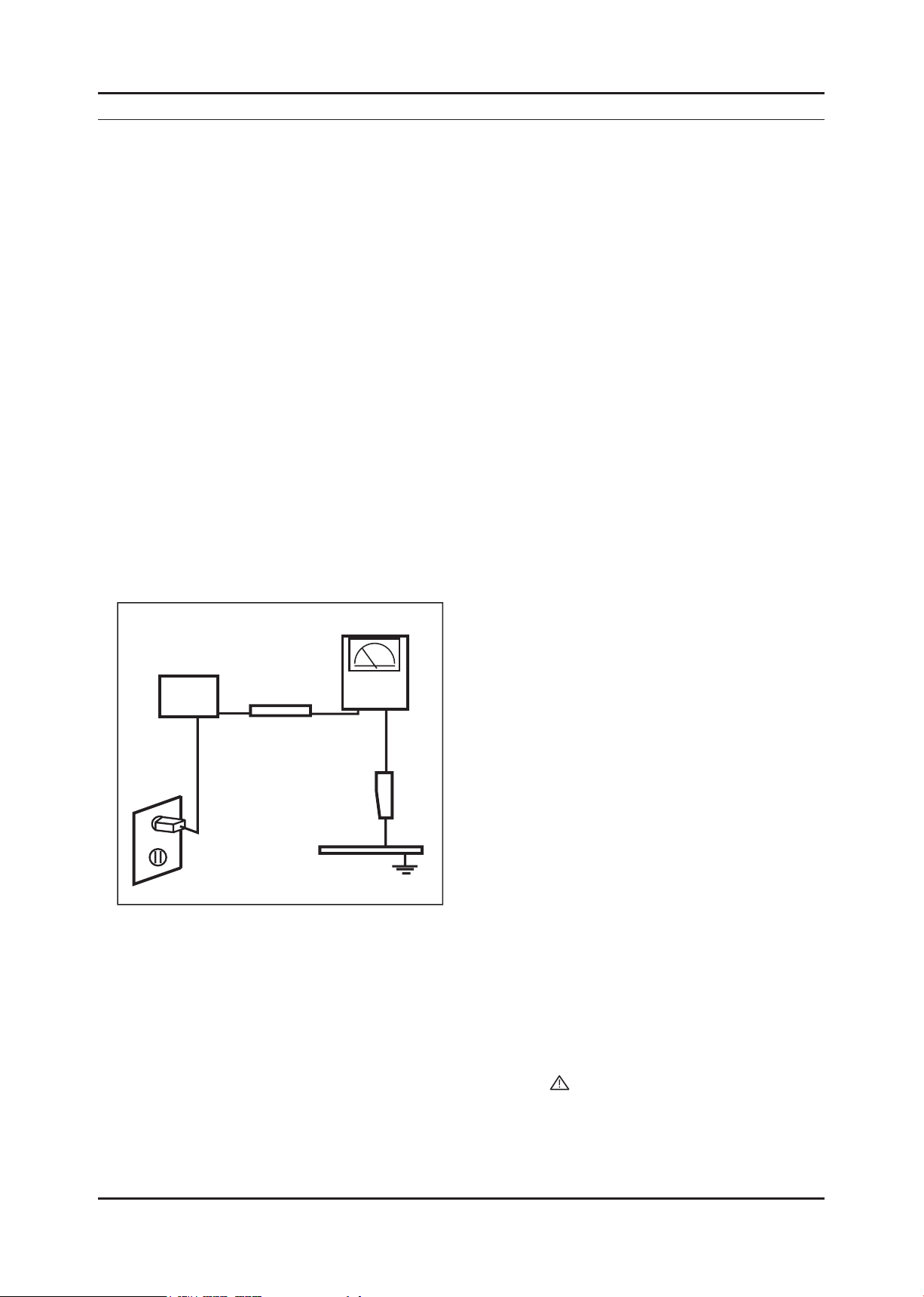
Leakage Current Hot Check (Figure 1-1): 3.
WARNING : Do not use an isolation transformer during this test.
Use a leakage current tester or a metering system that complies with American National Standards Institute (ANSI
C101.1, Leakage Current for Appliances), and Underwriters Laboratories (UL Publication UL1410, 59.7).
(READING SHOULD)
NOT BE ABOVE 0.5mA
DEVICE
UNDER
TEST
2-WIRE CORD
*ALSO TEST WITH
PLUG REVERSED
(USING AC ADAPTER
PLUG AS REQUIRED)
TEST ALL
EXPOSED METAL
SURFACES
LEAKAGE
CURRENT
TESTER
EARTH
GROUND
Figure 1-1. Leakage Current Test Circuit
With the unit completely reassembled, plug the AC line cord directly into a 120V AC outlet. With the unit’s AC switch 4.
rst in the ON position and then OFF, measure the current between a known earth ground (metal water pipe, conduit,
etc.) and all exposed metal parts, including: metal cabinets, screwheads and control shafts.
The current measured should not exceed 0.5 milliamp.
Reverse the power-plug prongs in the AC outlet and repeat the test.
1-1-4. Product Safety Notices
Some electrical and mechanical parts have special safetyrelated characteristics which are often not evident from visual
inspection. The protection they give may not be obtained by replacing them with components rated for higher voltage,
wattage, etc. Parts that have special safety characteristics are identied by on schematics and parts lists. A substitute
replacement that does not have the same safety characteristics as the recommended replacement part might create
shock, re and/or other hazards. Product safety is under review continuously and new instructions are issued whenever
appropriate.
1-1

1-2
1. Precautions
1-2. Servicing Precautions
WARNING: An electrolytic capacitor installed with the wrong polarity might explode.
Caution: Before servicing units covered by this service manual, read and follow the Safety Precautions section of
this manual.
Note: If unforeseen circumstances create conict between the following servicing precautions and any of the
safety precautions, always follow the safety precautions.
1-2-1 General Servicing Precautions
Always unplug the unit’s AC power cord from the AC power source and disconnect the DC Power Jack before 1.
attempting to:
(a) remove or reinstall any component or assembly, (b) disconnect PCB plugs or connectors, (c) connect a test
component in parallel with an electrolytic capacitor.
Some components are raised above the printed circuit board for safety. An insulation tube or tape is sometimes 2.
used. The internal wiring is sometimes clamped to prevent contact with thermally hot components. Reinstall all such
elements to their original position.
After servicing, always check that the screws, components and wiring have been correctly reinstalled. Make sure that 3.
the area around the serviced part has not been damaged.
Check the insulation between the blades of the AC plug and accessible conductive parts (examples: metal panels, 4.
input terminals and earphone jacks).
Insulation Checking Procedure: Disconnect the power cord from the AC source and turn the power switch ON. 5.
Connect an insulation resistance meter (500 V) to theblades of the AC plug.
The insulation resistance between each blade of the AC plug and accessible conductive parts (see above) should be
greater than 1 megohm.
Always connect a test instrument’s ground lead to the instrument chassis ground before connecting the positive lead; 6.
always remove the instrument’s ground lead last.
1-3. Electrostatically Sensitive Devices (ESD) Precautions
Some semiconductor (solid state) devices can be easily damaged by static electricity. Such components are commonly
called Electrostatically Sensitive Devices (ESD). Examples of typical ESD are integrated circuits and some eld-effect
transistors. The following techniques will reduce the incidence of component damage caused by static electricity.
Immediately before handling any semiconductor components or assemblies, drain the electrostatic charge from your 1.
body by touching a known earth ground. Alternatively, wear a discharging wrist-strap device. To avoid a shock hazard,
be sure to remove the wrist strap before applying power to the LED TV.
After removing an ESD-equipped assembly, place it on a conductive surface such as aluminum foil to prevent 2.
accumulation of an electrostatic charge.
Do not use freon-propelled chemicals. These can generate electrical charges sufcient to damage ESDs.3.
Use only a grounded-tip soldering iron to solder or desolder ESDs.4.
Use only an anti-static solder removal device. Some solder removal devices not classied as “anti-static” can generate 5.
electrical charges sufcient to damage ESDs.
Do not remove a replacement ESD from its protective package until you are ready to install it. Most replacement ESDs 6.
are packaged with leads that are electrically shorted together by conductive foam, aluminum foil or other conductive
materials.
Immediately before removing the protective material from the leads of a replacement ESD, touch the protective 7.
material to the chassis or circuit assembly into which the device will be installed.
Caution: Be sure no power is applied to the chassis or circuit and observe all other safety precautions.
Minimize body motions when handling unpackaged replacement ESDs. Motions such as brushing clothes together, 8.
or lifting your foot from a carpeted oor can generate enough static electricity to damage an ESD.

1-3
1. Precautions
1-4. Installation Precautions
For safety reasons, more than a people are required for carrying the product.1.
Keep the power cord away from any heat emitting devices, as a melted covering may cause re or electric shock.2.
Do not place the product in areas with poor ventilation such as a bookshelf or closet. The increased internal 3.
temperature may cause re.
Bend the external antenna cable when connecting it to the product. This is a measure to protect it from being exposed 4.
to moisture. Otherwise, it may cause a re or electric shock.
Make sure to turn the power off and unplug the power cord from the outlet before repositioning the product. Also check 5.
the antenna cable or the external connectors if they are fully unplugged. Damage to the cord may cause re or electric
shock.
Keep the antenna far away from any high-voltage cables and install it rmly. Contact with the highvoltage cable or the 6.
antenna falling over may cause re or electric shock.
When installing the product, leave enough space (0.4m) between the product and the wall for ventilation purposes. 7.
A rise in temperature within the product may cause re.

1. Precautions
Memo
1-4
2. Product specications
2-1. Feature & Specications
Model UA32C5000Q
Feature
DTV/ATV, 4-HDMI, 1-Component, 1-A/V, D-SUB, 2-USB2.0 ሪ
Brightness : 450 cd/m ሪ
High Contrast Ratio : 50,000:1 ሪ
Response Time : 4.5ms ሪ
Item Description
LCD Panel 32inch FHD 60Hz
Scanning Frequency Horizontal : 30 kHz ~ 80 kHz (Automatic)
Display Colors 16.7M color
Maximum resolution Horizontal : 1920 Pixels
2
Specications
Vertical : 47 Hz ~ 75 Hz (Automatic)
Vertical : 1080 pixels
2. Product specications
Input Signal Analog 0.7 Vp-p ± 5% positive at 75Ω , internally terminated
Input Sync Signal H/V Separate, TTL, P. or N.
Maximum Pixel Clock rate 74.25MHz
Active Display
Horizontal/Vertical
AC power voltage & Frequency AC 100V ~ 240V, 50/60Hz
Power Consumption Under 110W (Under 0.3W, Stand by)
Dimensions
Set (W x D x H)
Weight 24.25 Ibs (11kg)_with stand
TV System Tuning Frequency Synthesize (Refer to detailed Frequency Table)
Environmental Considerations Operating Temperature : 32˚F ~ 122˚F (0˚C ~ 50˚C)
27.50 x 15.47 inches (698.4(H) x 392.85(V) mm)
30.9 x 9.4 x 21.6 inches (785 x 240 x 550 mm)_with stand
30.9 x 1.2 x 19.3 inches (785 x 29.9 x 491 mm)_without stand
18.08 Ibs (8.2kg)_without stand
System DVB-T/C, PAL, SECAM, NT4.43
Sound BG, DK, L/L’, NICAM, MPEG1, DD, DD+, HE-AAC
Operating Humidity : 10% ~ 90%, non-condensing
Storage temperature : -4˚F ~ 140˚F (-20˚C ~ 60˚C)
Storage Humidity : 10% ~ 90%
Audio Spec. - MAX Internal Audio Output Power : Each 10W(Left/Right)
- BASS Control Range : -8 dB ~ + 8dB
- TREBLE Control Range : -8 dB ~ +8 dB
- Headphone Out : 10 mW MAX
- Output Frequency : RF : 80 Hz ~ 15 kHz
AV/Componet/HDMI : 80 Hz ~ 20 kHz
Note: DLNA, Dolby Digital+, Game Mode, Film Mode, Energy Saving, Anynet+
2-1
2-2
2. Product specications
Model UA37C5000Q
Feature
DTV/ATV, 4-HDMI, 1-Component, 1-A/V, D-SUB, 2-USB2.0 ሪ
Brightness : 450 cd/m ሪ
2
High Contrast Ratio : 50,000:1 ሪ
Response Time : 4.5 ms ሪ
Specications
Item Description
LCD Panel 37inch FHD 60Hz
Scanning Frequency Horizontal : 30 kHz ~ 80 kHz (Automatic)
Vertical : 47 Hz ~ 63 Hz (Automatic)
Display Colors 16.7M color
Maximum resolution Horizontal : 1920 Pixels
Vertical : 1080 pixels
Input Signal Analog 0.7 Vp-p ± 5% positive at 75Ω , internally terminated
Input Sync Signal H/V Separate, TTL, P. or N.
Maximum Pixel Clock rate 74.25MHz
Active Display
Horizontal/Vertical
32.26 x 18.15 inches (819.36(H) x 460.89(V) mm)
AC power voltage & Frequency AC 100V ~ 240V, 50/60Hz
Power Consumption Under 120W (Under 0.3W, Stand by)
Dimensions
Set (W x D x H)
35.7 x 10.0 x 24.4 inches (908 x 255 x 621 mm)_with stand
35.7 x 1.2 x 22.1 inches (908 x 29.9 x 561 mm)_without stand
Weight 31.30 Ibs (14.2kg)_with stand
23.37 Ibs (10.6kg)_without stand
TV System Tuning Frequency Synthesize (Refer to detailed Frequency Table)
System DVB-T/C, PAL, SECAM, NT4.43
Sound BG, DK, L/L’, NICAM, MPEG1, DD, DD+, HE-AAC
Environmental Considerations Operating Temperature : 32˚F ~ 122˚F (0˚C ~ 50˚C)
Operating Humidity : 10% ~ 90%, non-condensing
Storage temperature : -4˚F ~ 140˚F (-20˚C ~ 60˚C)
Storage Humidity : 10% ~ 90%
Audio Spec. - MAX Internal Audio Output Power : Each 10W(Left/Right)
- BASS Control Range : -8 dB ~ + 8dB
- TREBLE Control Range : -8 dB ~ +8 dB
- Headphone Out : 10 mW MAX
- Output Frequency : RF : 80 Hz ~ 15 kHz
AV/Componet/HDMI : 80 Hz ~ 20 kHz
Note: DLNA, Dolby Digital+, Game Mode, Film Mode, Energy Saving, Anynet+

2-3
2. Product specications
Model UA40C5000Q
Feature
DTV/ATV, 4-HDMI, 1-Component, 1-A/V, D-SUB, 2-USB2.0 ሪ
Brightness : 450 cd/m ሪ
2
High Contrast Ratio : 50,000:1 ሪ
Response Time : 4.5 ms ሪ
Specications
Item Description
LCD Panel 40inch FHD 60Hz
Scanning Frequency Horizontal : 30 kHz ~ 80 kHz (Automatic)
Vertical : 47 Hz ~ 63 Hz (Automatic)
Display Colors 16.7M color
Maximum resolution Horizontal : 1920 Pixels
Vertical : 1080 pixels
Input Signal Analog 0.7 Vp-p ± 5% positive at 75Ω , internally terminated
Input Sync Signal H/V Separate, TTL, P. or N.
Maximum Pixel Clock rate 74.25MHz
Active Display
Horizontal/Vertical
34.87 x 22.55 inches (885.6(H) x 19.61(V) mm)
AC power voltage & Frequency AC 100V ~ 240V, 50/60Hz
Power Consumption Under 130W (Under 0.3W, Stand by)
Dimensions
Set (W x D x H)
38.3 x 10.0 x 24.4 inches (972 x 255 x 621 mm)_with stand
38.3 x 1.2 x 23.5 inches (972 x 29.9 x 596 mm)_without stand
Weight 34.61 Ibs (15.7kg)_with stand
26.68 Ibs (12.1kg)_without stand
TV System Tuning Frequency Synthesize (Refer to detailed Frequency Table)
System DVB-T/C, PAL, SECAM, NT4.43
Sound BG, DK, L/L’, NICAM, MPEG1, DD, DD+, HE-AAC
Environmental Considerations Operating Temperature : 32˚F ~ 122˚F (0˚C ~ 50˚C)
Operating Humidity : 10% ~ 90%, non-condensing
Storage temperature : -4˚F ~ 140˚F (-20˚C ~ 60˚C)
Storage Humidity : 10% ~ 90%
Audio Spec. - MAX Internal Audio Output Power : Each 10W(Left/Right)
- BASS Control Range : -8 dB ~ + 8dB
- TREBLE Control Range : -8 dB ~ +8 dB
- Headphone Out : 10 mW MAX
- Output Frequency : RF : 80 Hz ~ 15 kHz
AV/Componet/HDMI : 80 Hz ~ 20 kHz
Note: DLNA, Dolby Digital+, Game Mode, Film Mode, Energy Saving, Anynet
+

2-4
2. Product specications
Model UA46C5000Q
Feature
DTV/ATV, 4-HDMI, 1-Component, 1-A/V, D-SUB, 2-USB2.0 ሪ
Brightness : 450 cd/m ሪ
2
High Contrast Ratio : 50,000:1 ሪ
Response Time : 4.5ms ሪ
Specications
Item Description
LCD Panel 46inch FHD 60Hz
Scanning Frequency Horizontal : 30 kHz ~ 80 kHz (Automatic)
Vertical : 47 Hz ~ 63 Hz (Automatic)
Display Colors 16.7M color
Maximum resolution Horizontal : 1920 Pixels
Vertical : 1080 pixels
Input Signal Analog 0.7 Vp-p ± 5% positive at 75Ω , internally terminated
Input Sync Signal H/V Separate, TTL, P. or N.
Maximum Pixel Clock rate 74.25MHz
Active Display
Horizontal/Vertical
40.08 x 22.55 inches (1018.08(H) x 572.67(V) mm)
AC power voltage & Frequency AC 100V ~ 240V, 50/60Hz
Power Consumption Under 130W (Under 0.3W, Stand by)
Dimensions
Set (W x D x H)
43.6 x 10.8 x 28.8 inches (1107 x 275 x 731 mm)_with stand
43.6 x 1.2 x 26.4 inches (1107 x 29.9 x 671 mm)_without stand
Weight 43.43 Ibs (19.7kg)_with stand
34.61 Ibs (15.7kg)_without stand
TV System Tuning Frequency Synthesize (Refer to detailed Frequency Table)
System DVB-T/C, PAL, SECAM, NT4.43
Sound BG, DK, L/L’, NICAM, MPEG1, DD, DD+, HE-AAC
Environmental Considerations Operating Temperature : 32˚F ~ 122˚F (0˚C ~ 50˚C)
Operating Humidity : 10% ~ 90%, non-condensing
Storage temperature : -4˚F ~ 140˚F (-20˚C ~ 60˚C)
Storage Humidity : 10% ~ 90%
Audio Spec. - MAX Internal Audio Output Power : Each 10W(Left/Right)
- BASS Control Range : -8 dB ~ + 8dB
- TREBLE Control Range : -8 dB ~ +8 dB
- Headphone Out : 10 mW MAX
- Output Frequency : RF : 80 Hz ~ 15 kHz
AV/Componet/HDMI : 80 Hz ~ 20 kHz
Note: DLNA, Dolby Digital+, Game Mode, Film Mode, Energy Saving, Anynet
+
2-5
2. Product specications
Model UA32C4000P
Feature
DTV/ATV, 4-HDMI, 1-Component, 1-A/V, D-SUB, 2-USB2.0 ሪ
Brightness : 400 cd/m ሪ
2
High Contrast Ratio : 40,000:1 ሪ
Response Time : 4.5ms ሪ
Specications
Item Description
LCD Panel 32inch HD 60Hz
Scanning Frequency Horizontal : 30 kHz ~ 80 kHz (Automatic)
Vertical : 47 Hz ~ 75 Hz (Automatic)
Display Colors 16.7M color
Maximum resolution Horizontal : 1366 Pixels
Vertical : 768 pixels
Input Signal Analog 0.7 Vp-p ± 5% positive at 75Ω , internally terminated
Input Sync Signal H/V Separate, TTL, P. or N.
Maximum Pixel Clock rate 74.25MHz
Active Display
Horizontal/Vertical
27.47 x 15.44 inches (697.69(H) x 392.26(V) mm)
AC power voltage & Frequency AC 100V ~ 240V, 50/60Hz
Power Consumption Under 100W (Under 0.3W, Stand by)
Dimensions
Set (W x D x H)
30.5 x 10.0 x 21.6 inchs (774.6 x 255.0 x 549.1 mm)_with stand
30.5 x 1.2 x 19.4 inchs (774.6 x 29.9 x 491.8 mm)_without stand
Weight 24.9 Ibs (11.3kg)_with stand
20.3 Ibs (9.2kg)_without stand
TV System Tuning Frequency Synthesize (Refer to detailed Frequency Table)
System DVB-T/C, PAL, SECAM, NT4.43
Sound BG, DK, L/L’, NICAM, MPEG1, DD, DD+, HE-AAC
Environmental Considerations Operating Temperature : 32˚F ~ 122˚F (0˚C ~ 50˚C)
Operating Humidity : 10% ~ 90%, non-condensing
Storage temperature : -4˚F ~ 140˚F (-20˚C ~ 60˚C)
Storage Humidity : 10% ~ 90%
Audio Spec. - MAX Internal Audio Output Power : Each 10W(Left/Right)
- BASS Control Range : -8 dB ~ + 8dB
- TREBLE Control Range : -8 dB ~ +8 dB
- Headphone Out : 10 mW MAX
- Output Frequency : RF : 80 Hz ~ 15 kHz
AV/Componet/HDMI : 80 Hz ~ 20 kHz
Note: Dolby Digital+, Game Mode, Film Mode, Energy Saving, Anynet
+

2-6
2. Product specications
2-2. Detail Factory Option
If you replace the main board with new one, please change the factory option as well. ※
The options you must change are “Type”.
Model Name UA32C5000QF UA37C5000QF UA40C5000QF UA46C5000QF UA32C4000PD
Panel
SMPS
1 Factory Reset
2 Type
3 Local set
4 Model
5 TUNER
6 DDR
7 Light Effect
8 Ch Table
9 Country
10 Front Color
Vendor
CODE
Vendor
CODE
-
19D6THOC ~ 52L6AFOC/
EU/EU_ltaly//NORDIG/AD_au/
CIS
UC4000/UC5000/UC5100/
UC6000
DRXKSEMCO/
DRXKALPS/.....
SAMSUNG / Etron
On/Off
SUWON/SESK/SHE/TTSEC/
SDMA/
SERK/SEIN/SAVINA/SIEL/
TSE
...
S-BLK/S-R-BLK/S-C-Gray/...
CMO AUO CMO AUO CMO
BN07-00849A BN07-00880A BN07-00856A BN07-00384A BN07-00848A
DYREL DYREL SEM DYREL DYREL
BN44-00351B BN44-00351B BN44-00353A BN44-00357B BN44-00349B
32P6UF0E 37P6UF0E 40P6UF0E 46P6UF0E 32P6AH0E
AD_Au AD_Au AD_Au AD_Au AD_Au
UC5000 UC5000 UC5000 UC5000 UC4000
DRXKAPLS DRXKAPLS DRXKAPLS DRXKAPLS DRXKAPLS
SAMSUNG SAMSUNG SAMSUNG SAMSUNG SAMSUNG
Off Off Off Off Off
SDMA SDMA SDMA SDMA SDMA
... ... ... ... ...
T-R-BLK T-R-BLK T-R-BLK T-R-BLK T-R-BLK

2-7
2. Product specications
CHANNEL FREQUENCY TABLE
OSD CH NO AIR CH NO CH NO CH NO
Air-DTV Air-NTSC BAND Cable STD BAND Cable HRC Cable IRC
1 1 A-8 72. 00 A-8 73. 25
2 2 57 55. 25 V-L 2 55. 25 V-L 2 54. 00 2 55. 25
3 3 63 61.25 V-L 3 61.25 V-L 3 60.00 3 61.25
4 4 69 67.25 V-L 4 67.25 V-L 4 66.00 4 67.25
5 5 79 77. 25 V-L 5 77. 25 V-L A-7 78. 00 A-7 79. 25
6 6 85 83.25 V-L 6 83.25 V-L A-6 84.00 A-6 85.25
7 7 177 175. 25 V-H 7 175. 25 V-H 7 174. 00 7 175. 25
8 8 183 181.25 V-H 8 181.25 V-H 8 180.00 8 181.25
9 9 189 187.25 V-H 9 187.25 V-H 9 186.00 9 187.25
10 10 195 193.25 V-H 10 1
93.25 V-H 10 192.00 10 193.25
11 11 201 199.25 V-H 11 199.25 V-H 11 198.00 11 199.25
12 12 207 205.25 V-H 12 205.25 V-H 12 204.00 12 205.25
13 13 213 211.25 V-H 13 211.25 V-H 13 210.00 13 211.25
14 14 473 471. 25 UHF A 121. 25 MID A 120. 00 A 121. 25
15 15 479 477.25 UHF B 127.25 MID B 126.00 B 127.25
16 16 485 483.25 UHF C 133.25 MID C 132.00 C 133.25
17 17 491 489.25 UHF D 139.25 MID D 138.00 D 139.25
18 18 497 495.25 UHF E 145.25 MID E 144.00 E 145.25
19 19 503 501.25 UHF F 151.25 MID F 150.00 F 151.25
20 20 509
507.25 UHF G 157.25 MID G 156.00 G 157.25
21 21 515 513.25 UHF H 163.25 MID H 162.00 H 163.25
22 22 521 519.25 UHF I 169.25 MID I 168.00 I 169.25
23 23 527 525.25 UHF J 217. 25 SUPER J 216. 00 J 217. 25
24 24 533 531.25 UHF K 223.25 SUPER K 222.00 K 223.25
25 25 539 537.25 UHF L 229.25 SUPER L 228.00 L 229.25
26 26 545 543.25 UHF M 235.25 SUPER M 234.00 M 235.25
27 27 551 549.25 UHF N 241.25 SUPER N 240.00 N 241.25
28 28 557 555.25 UHF O 247.25 SUPER O 246.00 O 247.25
29 29 563 561.25 UHF P 253.25 SUPER P 252.00
P 253.25
30 30 569 567.25 UHF Q 259.25 SUPER Q 258.00 Q 259.25
31 31 575 573.25 UHF R 265.25 SUPER R 264.00 R 265.25
32 32 581 579.25 UHF S 271.25 SUPER S 270.00 S 271.25
33 33 587 585.25 UHF T 277.25 SUPER T 276.00 T 277.25
34 34 593 591.25 UHF U 283.25 SUPER U 282.00 U 283.25
35 35 599 597.25 UHF V 289.25 SUPER V 288.00 V 289.25
36 36 605 603.25 UHF W 295.25 SUPER W 294.00 W 295.25
37 37 611 609.25 UHF AA 301.25 HYPER AA 300.00 AA 301.25
38 38 617 615.25 UHF BB 307.25 HYPER BB 306.00 BB 307.25
39 39 623 62
1.25 UHF CC 313.25 HYPER CC 312.00 CC 313.25
40 40 629 627.25 UHF DD 319.25 HYPER DD 318.00 DD 319.25
41 41 635 633.25 UHF EE 325.25 HYPER EE 324.00 EE 325.25
42 42 641 639.25 UHF FF 331.25 HYPER FF 330.00 FF 331.25
43 43 647 645.25 UHF GG 337.25 HYPER GG 336.00 GG 337.25
44 44 653 651.25 UHF HH 343.25 HYPER HH 342.00 HH 343.25
45 45 659 657.25 UHF II 349.25 HYPER II 348.00 II 349.25
46 46 665 663.25 UHF JJ 355.25 HYPER JJ 354.00 JJ 355.25
47 47 671 669.25 UHF KK 361.25 HYPER KK 360.00 KK 361.25
48 48
677 675.25 UHF LL 367.25 HYPER LL 366.00 LL 367.25
49 49 683 681.25 UHF MM 373.25 HYPER MM 372.00 MM 373.25
50 50 689 687.25 UHF NN 379.25 HYPER NN 378.00 NN 379.25
51 51 695 693.25 UHF OO 385.25 HYPER OO 384.00 OO 385.25
52 52 701 699.25 UHF PP 391.25 HYPER PP 390.00 PP 391.25
53 53 707 705.25 UHF QQ 397.25 HYPER QQ 396.00 QQ 397.25
54 54 713 711.25 UHF RR 403.25 HYPER RR 402.00 RR 403.25
55 55 719 717.25 UHF SS 409.25 HYPER SS 408.00 SS 409.25
56 56 725 723.25 UHF TT 415.25 HYPER TT 414.00 TT 415.2
5
57 57 731 729.25 UHF UU 421.25 HYPER UU 420.00 UU 421.25
58 58 737 735.25 UHF VV 427.25 HYPER VV 426.00 VV 427.25
59 59 743 741.25 UHF WW 433.25 HYPER WW 432.00 WW 433.25
60 60 749 747.25 UHF XX 439.25 HYPER XX 438.00 XX 439.25
61 61 755 753.25 UHF YY 445.25 HYPER YY 444.00 YY 445.25
62 62 761 759.25 UHF ZZ 451.25 HYPER ZZ 450.00 ZZ 451.25
63 63 767 765.25 UHF AAA 457.25 HYPER AAA 456.00 AAA 457.25
64 64 773 771.25 UHF BBB 463.25 HYPER BBB 462.00 BBB 463.25
65 65 779 777.25 UHF CCC 469.25 ULTRA CCC
468.00 CCC 469.25
66 66 785 783.25 UHF DDD 475.25 ULTRA DDD 474.00 DDD 475.25
67 67 791 789.25 UHF EEE 481.25 ULTRA EEE 480.00 EEE 481.25
68 68 797 795.25 UHF FFF 487.25 ULTRA FFF 486.00 FFF 487.25
69 69 803 801.25 UHF GGG 493.25 ULTRA GGG 492.00 GGG 493.25
1. OUTPUT FREQUENCY : ANALOG fv:45.75MHz, fs:41.25MHz DIGITAL Fc:44MHz
2. TUNING STEP SIZE : FIRST PLL 250KHz SECOND PLL 62.5KHz
 Loading...