

Samsung UA28F4000AR Schematic
LED TV
Chassis : U86B
Model : UA19F4000AR
UA28F4000AR
UA28F4100AR
UA22F5000AR
UA22F5100AR
SERVICE
LED TV Contents
1. Precautions
2. Product specications
3. Disassembly and Reassembly
4. Troubleshooting
5. Wiring Diagram
Manual
UA22F5000AR

Contents
1. Precautions ...................................................................................................................1-1
1-1. Safety Precautions ..............................................................................................................1-1
1-2. Servicing Precautions ..........................................................................................................1-3
1-3. Static Electricity Precautions ...............................................................................................1-4
1-4. Installation Precautions .......................................................................................................1-5
2. Product Specications.................................................................................................2-1
2-1. Product Information .............................................................................................................2-1
2-2. Accessories .........................................................................................................................2-9
3. Disassembly and Reassembly ....................................................................................3-1
3-1. Disassembly and Reassembly ............................................................................................3-1
3-2. Assy Board P-Jog Switch & Ir ..............................................................................................3-5
3-3. Disassembly(PTC) ...............................................................................................................3-7
4. Troubleshooting ...........................................................................................................4-1
4-1. Troubleshooting ................................................................................................................... 4-1
4-2. How to Check Fault Symptom .............................................................................................4-5
4-3. Factory Mode Adjustments .................................................................................................. 4-9
4-4. White Balance ...................................................................................................................4-24
4-5. White Ratio (Balance) Adjustment .....................................................................................4-27
4-6. Detail Specications ..........................................................................................................4-29
4-7. Software Upgrade ..............................................................................................................4-73
4-8. Rear Cover Dimension ......................................................................................................4-75
5. Wiring Diagram .............................................................................................................5-1
5-1. Wiring Diagram .................................................................................................................... 5-1
5-2. Connector ...........................................................................................................................5-3
5-3. Connector Functions ...........................................................................................................5-6
5-4. Cables .................................................................................................................................5-7

This Service Manual is a property of Samsung Electronics Co.,Ltd.
Any unauthorized use of Manual can be punished under applicable
International and/or domestic law.
© 2013 Samsung Electronics Co.,Ltd.
All rights reserved.
Printed in Korea
1. Precautions
1. Precautions
1-1. Safety Precautions
Follow these safety, servicing and ESD precautions to prevent damage and to protect against potential hazards such as
electrical shock.
1-1-1. Warnings
For continued safety, do not attempt to modify the circuit board.
WARNING
1-1-2. Servicing the LED TV
When servicing the LED TV, Disconnect the AC line cord from the AC outlet.1.
It is essential that service technicians have an accurate voltage meter available at all times. Check the calibration of this 2.
meter periodically.
1-1-3. Fire and Shock Hazard
Before returning the monitor to the user, perform the following safety checks:
Inspect each lead dress to make certain that the leads are not pinched or that hardware is not lodged between the 1.
chassis and other metal parts in the monitor.
Inspect all protective devices such as nonmetallic control knobs, insulating materials, cabinet backs, adjustment and 2.
compartment covers or shields, isolation resistorcapacitor networks, mechanical insulators, etc.
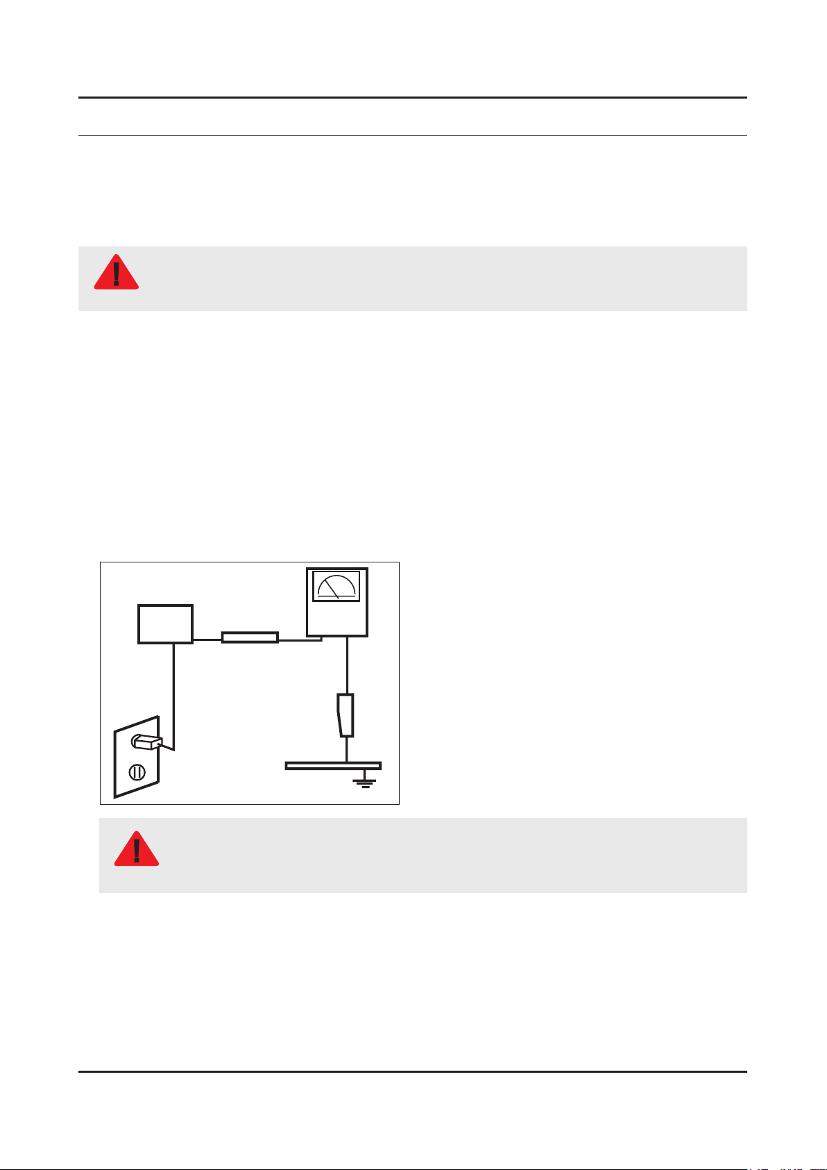
Leakage Current Hot Check:3.
Disconnect the AC power and DC power jack before servicing.
(READING SHOULD)
DEVICE
UNDER
TEST
ALSO TEST WITH
PLUG REVERSED
(USING AC ADAPTER
PLUG AS REQUIRED)
NOT BE ABOVE 0.5mA
2-WIRE CORD
TEST ALL
EXPOSED METAL
SURFACES
LEAKAGE
CURRENT
TESTER
EARTH
GROUND
Do not use an isolation transformer during this test.
Use a leakage current tester or a metering system that complies with American National Standards
WARNING
Institute (ANSI C101.1, Leakage Current for Appliances), and Underwriters Laboratories (UL
Publication UL1410, 59.7).
With the unit completely reassembled, plug the AC line cord directly into a 120V AC outlet. With the unit’s AC switch rst 4.
in the ON position and then OFF, measure the current between a known earth ground (metal water pipe, conduit, etc.)
and all exposed metal parts, including: metal cabinets, screwheads and control shafts.
The current measured should not exceed 0.5 milliamp.
Reverse the power-plug prongs in the AC outlet and repeat the test.
1-1
1-2
1. Precautions
1-1-4. Product Safety Notices
Some electrical and mechanical parts have special safetyrelated characteristics which are often not evident from visual
inspection. The protection they give may not be obtained by replacing them with components rated for higher voltage,
wattage, etc. Parts that have special safety characteristics are identied by on schematics and parts lists. A substitute
replacement that does not have the same safety characteristics as the recommended replacement part might create
shock, re and/or other hazards. Product safety is under review continuously and new instructions are issued whenever
appropriate.
1-3
1. Precautions
1-2. Servicing Precautions
An electrolytic capacitor installed with the wrong polarity might explode.
WARNING
Before servicing units covered by this service manual, read and follow the Safety Precautions section of
CAUTION
NOTE
1-2-1. General Servicing Precautions
Always unplug the unit’s AC power cord from the AC power source and disconnect the DC Power Jack before 1.
attempting to: (a) remove or reinstall any component or assembly, (b) disconnect PCB plugs or connectors, (c) connect
a test component in parallel with an electrolytic capacitor.
Some components are raised above the printed circuit board for safety. An insulation tube or tape is sometimes used. 2.
The internal wiring is sometimes clamped to prevent contact with thermally hot components. Reinstall all such elements
to their original position.
After servicing, always check that the screws, components and wiring have been correctly reinstalled. Make sure that 3.
the area around the serviced part has not been damaged.
Check the insulation between the blades of the AC plug and accessible conductive parts (examples: metal panels, input 4.
terminals and earphone jacks).
Insulation Checking Procedure: Disconnect the power cord from the AC source and turn the power switch ON. Connect 5.
an insulation resistance meter (500 V) to theblades of the AC plug. The insulation resistance between each blade of the
AC plug and accessible conductive parts (see above) should be greater than 1 megohm.
Always connect a test instrument’s ground lead to the instrument chassis ground before connecting the positive lead; 6.
always remove the instrument’s ground lead last.
this manual.
If unforeseen circumstances create conict between the following servicing precautions and any of the
safety precautions, always follow the safety precautions.
1-4
1. Precautions
1-3. Static Electricity Precautions
Some semiconductor (solid state) devices can be easily damaged by static electricity. Such components are commonly
called Electrostatically Sensitive Devices (ESD). Examples of typical ESD are integrated circuits and some eld-effect
transistors. The following techniques will reduce the incidence of component damage caused by static electricity.
Immediately before handling any semiconductor components or assemblies, drain the electrostatic charge from your 1.
body by touching a known earth ground. Alternatively, wear a discharging wrist-strap device. To avoid a shock hazard,
be sure to remove the wrist strap before applying power to the monitor.
After removing an ESD-equipped assembly, place it on a conductive surface such as aluminum foil to prevent 2.
accumulation of an electrostatic charge.
Do not use freon-propelled chemicals. These can generate electrical charges sufcient to damage ESDs.3.
Use only a grounded-tip soldering iron to solder or desolder ESDs.4.
Use only an anti-static solder removal device. Some solder removal devices not classied as “anti-static” can generate 5.
electrical charges sufcient to damage ESDs.
Do not remove a replacement ESD from its protective package until you are ready to install it. Most replacement ESDs 6.
are packaged with leads that are electrically shorted together by conductive foam, aluminum foil or other conductive
materials.
Immediately before removing the protective material from the leads of a replacement ESD, touch the protective material 7.
to the chassis or circuit assembly into which the device will be installed.
Be sure no power is applied to the chassis or circuit and observe all other safety precautions.
CAUTION
Minimize body motions when handling unpackaged replacement ESDs. Motions such as brushing clothes together, or 8.
lifting your foot from a carpeted oor can generate enough static electricity to damage an ESD.

1-5
1. Precautions
1-4. Installation Precautions
For safety reasons, more than a people are required for carrying the product.1.
Keep the power cord away from any heat emitting devices, as a melted covering may cause re or electric shock.2.
Do not place the product in areas with poor ventilation such as a bookshelf or closet. The increased internal temperature 3.
may cause re.
Bend the external antenna cable when connecting it to the product. This is a measure to protect it from being exposed 4.
to moisture. Otherwise, it may cause a re or electric shock.
Make sure to turn the power off and unplug the power cord from the outlet before repositioning the product. Also check 5.
the antenna cable or the external connectors if they are fully unplugged. Damage to the cord may cause re or electric
shock.
Keep the antenna far away from any high-voltage cables and install it rmly. Contact with the highvoltage cable or the 6.
antenna falling over may cause re or electric shock.
When installing the product, leave enough space (0.4m) between the product and the wall for ventilation purposes. 7.
A rise in temperature within the product may cause re.
2. Product Specications
2-1. Product Information
2-1-1. Model Comparison
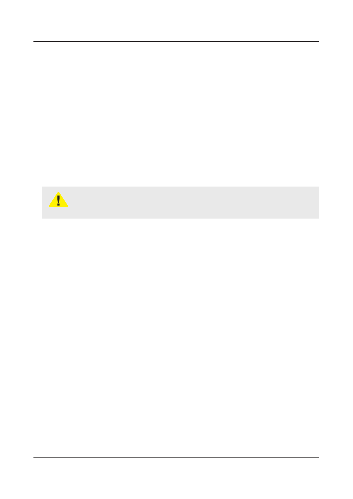
Model UA22F5000AR / UA22F5100AR
2. Product specications
W
Front View
D
Detail View
Front Color Black (Panel)
Set with
Dimensions
(W x H x D)
Weight 22"
Panel Type Anti Glare
22"
Stand
Set without
Stand
Set with
Stand
Set without
Stand
513.1 x 366.5 x 169.6 mm / 20.2 x 14.4 x 6.7 inches
513.1 x 321.5 x 43.8 mm / 20.2 x 12.7 x 1.7 inches
* W : Width H : High D : Depth
H
2.9 kg / 6.4 lbs
2.6 kg / 5.7 lbs
Internal Memory 128 Mbyte
DDR 256 Mbyte
Feature Media Play, Magic Angle
2-1
2-2
2. Product specications
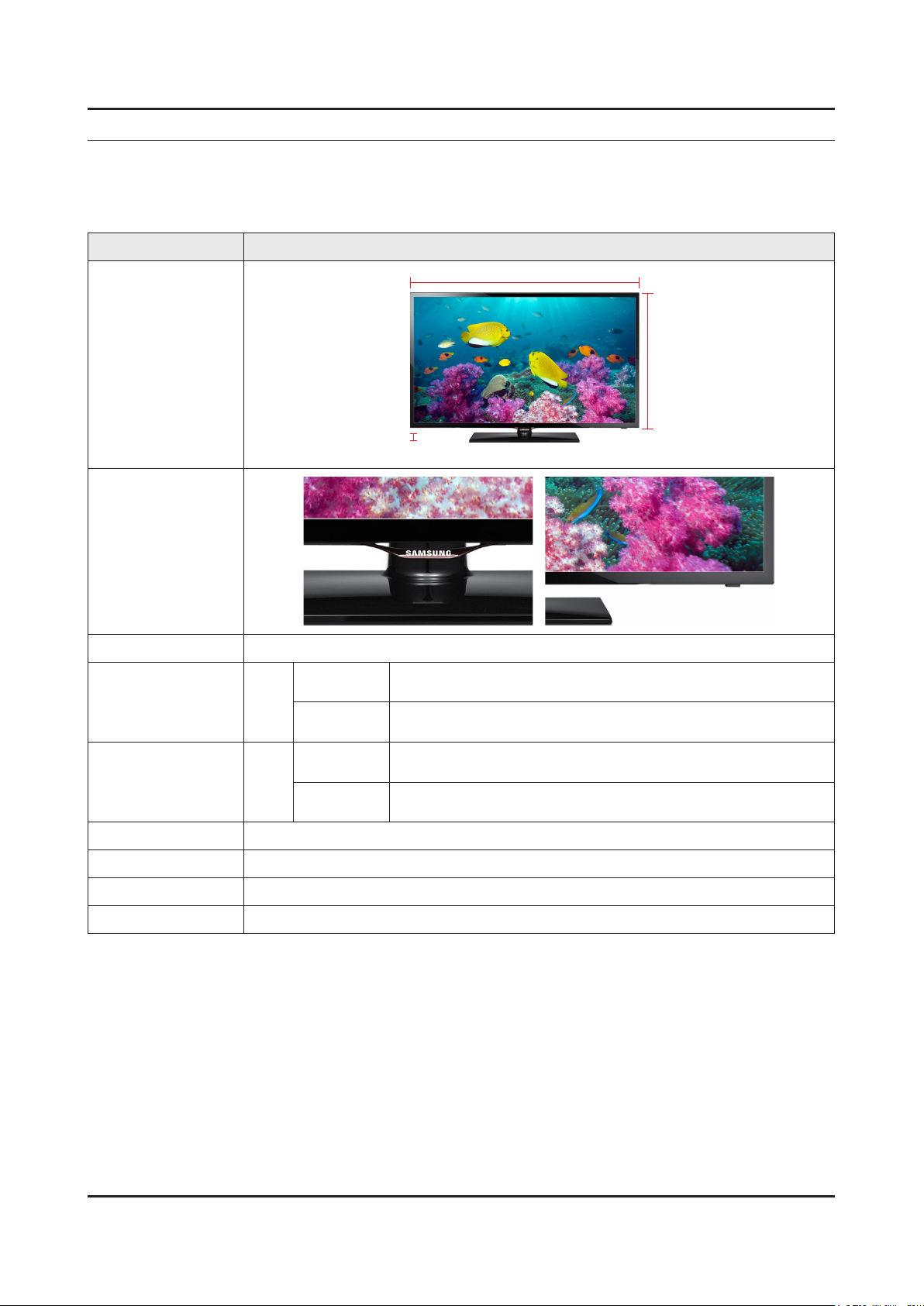
Model UA**F4000AR / UA**F4100AR
W
Front View
D
* W : Width H : High D : Depth
Detail View
Front Color Black (Panel)
Dimensions
(W x H x D)
19"
28"
Set with
Stand
Set without
Stand
Set with
Stand
Set without
Stand
Set with
Stand
453.7 x 314.2 x 151.4 mm / 17.9 x 12.4 x 6.0 inches
453.7 x 281.3 x 49.5 mm / 17.9 x 11.1 x 1.9 inches
645.0 x 435.6 x 252.6 mm / 25.4 x 17.1 x 9.9 inches
645.0 x 384.9 x 49.5 mm / 25.4 x 15.2 x 1.9 inches
2.6 kg / 5.7 lbs
19"
Set without
Stand
2.5 kg / 5.5 lbs
Weight
Set with
Stand
4.7 kg / 10.4 lbs
28"
Set without
Stand
4.2 kg / 9.3 lbs
H
Panel Type Anti Glare
Internal Memory 128 Mbyte
DDR 256 Mbyte
Feature Media Play, Magic Angle(19")
2-3
2. Product specications
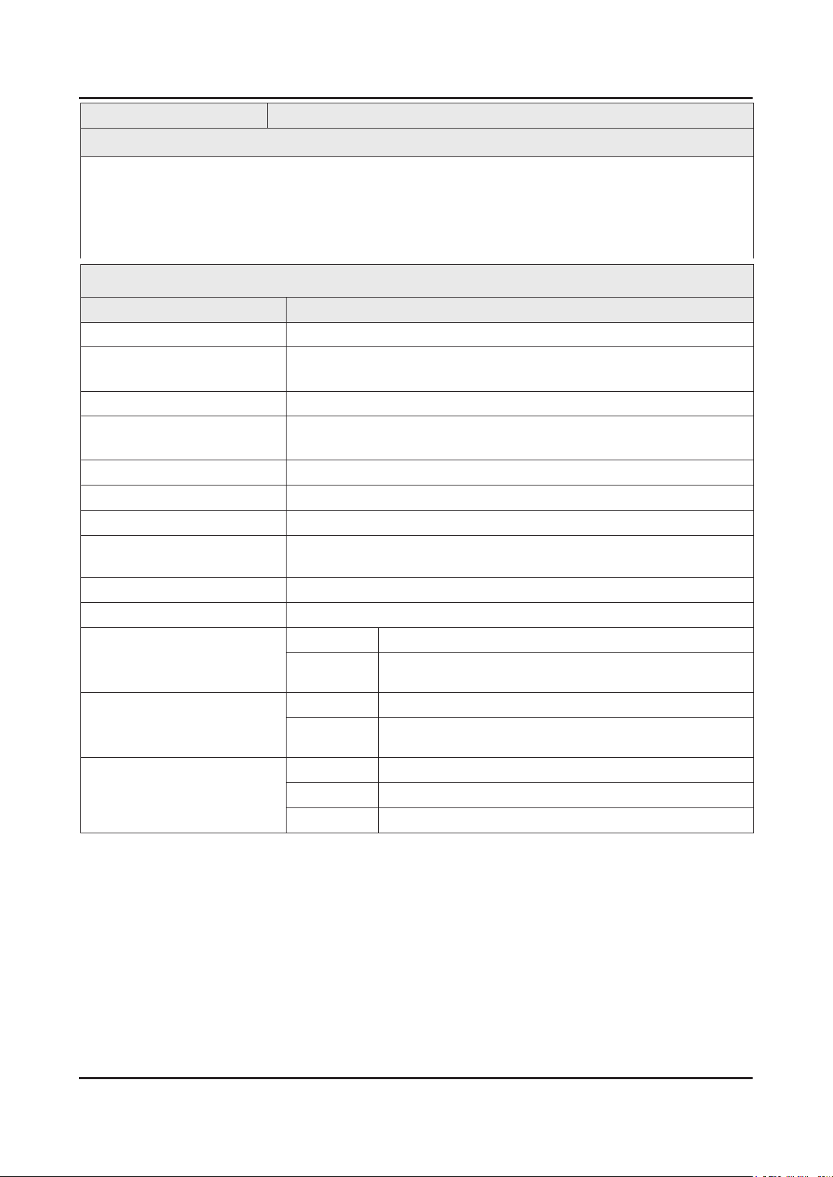
2-1-2. Feature & Specications
Model UA22F5000AR / UA22F5100AR
Feature
Digital-TV, RF, 2-HDMI, 1-Component, 1-A/V(Common Use for Component Y), 1-USB2.0, Headphone•
Brightness : 250 cd/m•
Dynamic Contrast Ratio : Mega DCR•
Response Time : 6.5 ms•
CMR : 100•
Item Description
LCD Panel 21.5 inch FHD 60Hz
Scanning Frequency Horizontal : 60 kHz ~ 73 kHz (Automatic)
Display Colors 16.7M colors
Maximum Resolution Horizontal : 1920 Pixels
2
Specications
Vertical : 47 Hz ~ 63 Hz (Automatic)
Vertical : 1080 Pixels
Input Signal Analog 0.7 Vp-p ± 5% positive at 75Ω, internally terminated
Input Sync Signal H/V Separate, TTL, P. or N.
Maximum Pixel Clock Rate 74.25 MHz
Active Display (H x V)*
* Horizontal x Vertical
476.6(H) X 268.1(V) (mm) / 18.8(H) X 10.6(V) (inches)
AC Power Voltage & Frequency AC 110V ~ 240V, 50/60 Hz
Power Consumption 35 W (Under 0.3 W, Stand by), (DC 14V)
Dimensions Set (W x H x D)*
* Width x High x Depth
Set with Stand 513.1 x 366.5 x 169.6 mm / 20.2 x 14.4 x 6.7 inches
Set without
Stand
513.1 x 321.5 x 43.8 mm / 20.2 x 12.7 x 1.7 inches
Weight Set with Stand 2.9 kg / 6.4 lbs
Set without
Stand
2.6 kg / 5.7 lbs
TV System Tuning Frequency Synthesize (Refer to detailed Frequency Table)
System PAL , SECAM , NT4.43, NT3.58
Sound PAL-B/G/I/D/K, Dolby Digital Plus/Pulse
2-4
2. Product specications
Specications
Item Description
Environmental Considerations Operating Temperature : 50˚F ~ 104˚F (10˚C ~ 40˚C)
Operating Humidity : 10% ~ 80%, non-condensing
Storage Temperature : -4˚F ~ 113˚F (-20˚C ~ 45˚C)
Storage Humidity : 5% ~ 95%, non-condensing
Audio Specications MAX Internal Audio Output Power : Each 3 W(Left/Right)
Equalizer : 5 Band
Output Frequency :
RF : 20 Hz ~ 15.4 kHz•
AV/Componet/HDMI : 20 Hz ~ 20 kHz•
Note : Dolby Digital Plus/Pulse, USB2.0, Film mode, Energy Saving, Eco sensor, Magic Angle
2-5
2. Product specications
Model UA19F4000AR
Feature
Digital-TV, RF, 2-HDMI, 1-Component, 1-A/V(Common Use for Component Y), 1-USB2.0, Headphone•
Brightness : 250 cd/m•
2
Dynamic Contrast Ratio : Mega DCR•
Response Time : 6.5 ms•
CMR : 100•
Specications
Item Description
LCD Panel 18.5 inch HD 60Hz
Scanning Frequency Horizontal : 60 kHz ~ 73 kHz (Automatic)
Vertical : 47 Hz ~ 63 Hz (Automatic)
Display Colors 16.7M colors
Maximum Resolution Horizontal : 1366 Pixels
Vertical : 768 Pixels
Input Signal Analog 0.7 Vp-p ± 5% positive at 75Ω, internally terminated
Input Sync Signal H/V Separate, TTL, P. or N.
Maximum Pixel Clock Rate 74.25 MHz
Active Display (H x V)*
* Horizontal x Vertical
409.8(H) X 230.4(V) (mm) / 16.1(H) X 9.1(V) (inches)
AC Power Voltage & Frequency AC 110V ~ 240V, 50/60 Hz
Power Consumption 35 W (Under 0.3 W, Stand by), (DC 14V)
Dimensions Set (W x H x D)*
* Width x High x Depth
Set with Stand 453.7 x 314.2 x 151.4 mm / 17.9 x 12.4 x 6.0 inches
Set without
Stand
453.7 x 281.3 x 49.5 mm / 29.1 x 11.1 x 1.9 inches
Weight Set with Stand 2.6 kg / 5.7 lbs
Set without
Stand
2.5 kg / 5.5 lbs
TV System Tuning Frequency Synthesize (Refer to detailed Frequency Table)
System PAL , SECAM , NT4.43, NT3.58
Sound PAL-B/G/I/D/K, Dolby Digital Plus/Pulse

2-6
2. Product specications
Specications
Item Description
Environmental Considerations Operating Temperature : 50˚F ~ 104˚F (10˚C ~ 40˚C)
Operating Humidity : 10% ~ 80%, non-condensing
Storage Temperature : -4˚F ~ 113˚F (-20˚C ~ 45˚C)
Storage Humidity : 5% ~ 95%, non-condensing
Audio Specications MAX Internal Audio Output Power : Each 3 W(Left/Right)
Equalizer : 5 Band
Output Frequency :
RF : 20 Hz ~ 15.4 kHz•
AV/Componet/HDMI : 20 Hz ~ 20 kHz•
Note : Dolby Digital Plus/Pulse, USB2.0, Film mode, Energy Saving, Magic Angle
2-7
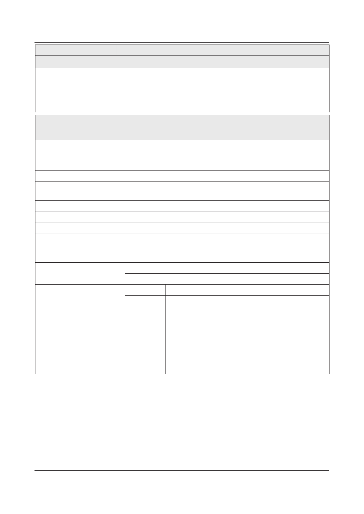
2. Product specications
Model UA28F4000AR / UA28F4100AR
Feature
Digital-TV, RF, 2-HDMI, 1-Component, 1-A/V(Common Use for Component Y), 1-USB2.0, Headphone•
Brightness : 250 cd/m•
2
Dynamic Contrast Ratio : Mega DCR•
Response Time : 6.5 ms•
CMR : 100•
Specications
Item Description
LCD Panel 27.5 inch HD 60Hz
Scanning Frequency Horizontal : 60 kHz ~ 73 kHz (Automatic)
Vertical : 47 Hz ~ 63 Hz (Automatic)
Display Colors 16.7M colors
Maximum Resolution Horizontal : 1366 Pixels
Vertical : 768 Pixels
Input Signal Analog 0.7 Vp-p ± 5% positive at 75Ω, internally terminated
Input Sync Signal H/V Separate, TTL, P. or N.
Maximum Pixel Clock Rate 74.25 MHz
Active Display (H x V)*
* Horizontal x Vertical
607.5(H) X 345.0(V) (mm) / 23.9(H) X 14.1(V) (inches)
AC Power Voltage & Frequency AC 110V ~ 240V, 50/60 Hz
Power Consumption 46 W (Under 0.3 W, Stand by), (AC 220-240V, 50/60Hz)
47 W (Under 0.3 W, Stand by), (AC 100-240V, 50/60Hz)
Dimensions Set (W x H x D)*
* Width x High x Depth
Set with Stand 645.0 x 435.6 x 252.6 mm / 25.4 x 17.1 x 9.9 inches
Set without
Stand
645.0 x 384.9 x 49.5 mm / 25.4 x 15.2 x1.9 inches
Weight Set with Stand 4.7 kg / 10.4 lbs
Set without
Stand
4.2 kg / 9.3 lbs
TV System Tuning Frequency Synthesize (Refer to detailed Frequency Table)
System PAL , SECAM , NT4.43, NT3.58
Sound PAL-B/G/I/D/K, Dolby Digital Plus/Pulse
2-8
2. Product specications
Specications
Item Description
Environmental Considerations Operating Temperature : 50˚F ~ 104˚F (10˚C ~ 40˚C)
Operating Humidity : 10% ~ 80%, non-condensing
Storage Temperature : -4˚F ~ 113˚F (-20˚C ~ 45˚C)
Storage Humidity : 5% ~ 95%, non-condensing
Audio Specications MAX Internal Audio Output Power : Each 3 W(Left/Right)
Equalizer : 5 Band
Output Frequency :
RF : 20 Hz ~ 15.4 kHz•
AV/Componet/HDMI : 20 Hz ~ 20 kHz•
Note : Dolby Digital Plus/Pulse, USB2.0, Film mode, Energy Saving
2-9
2. Product specications
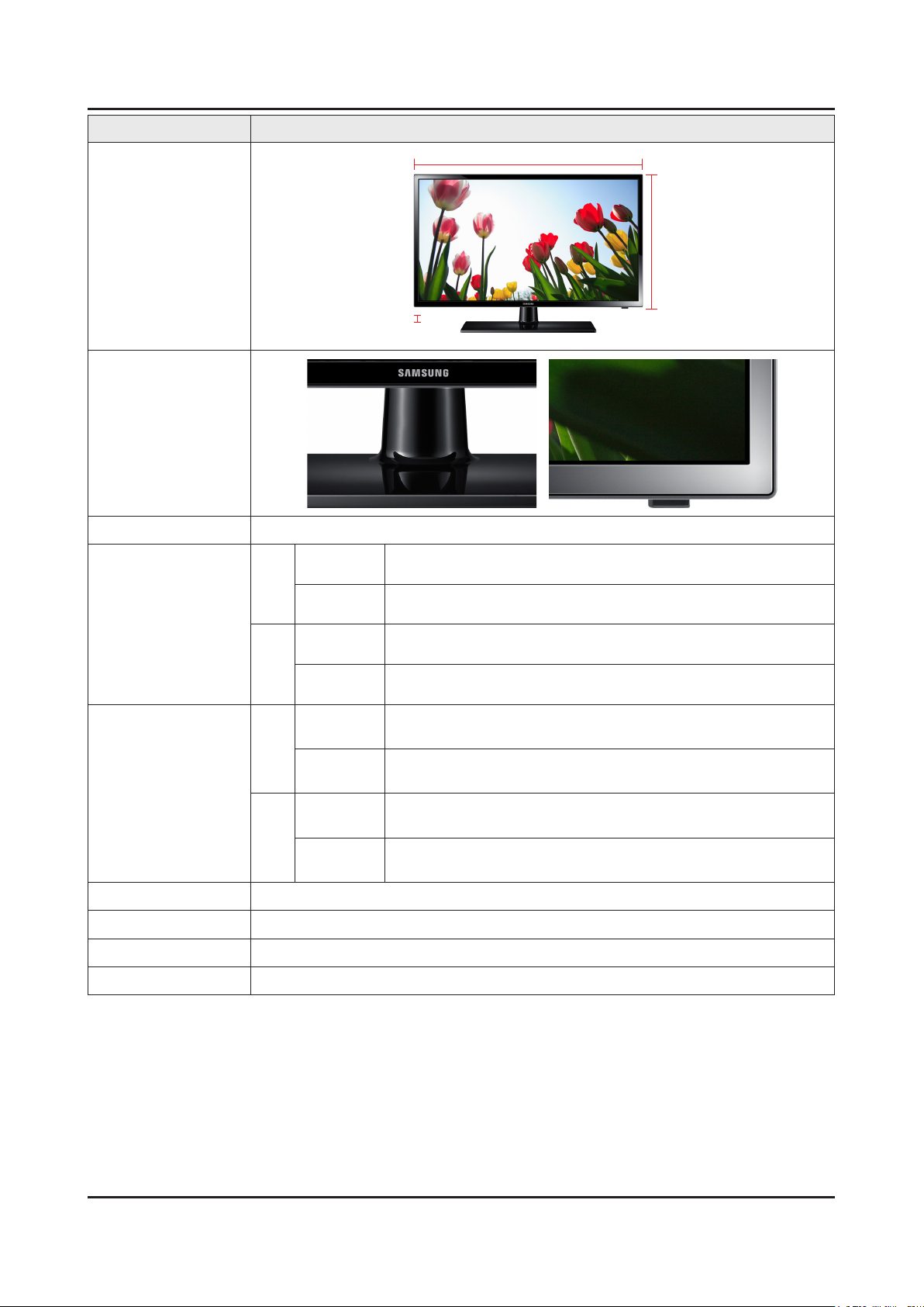
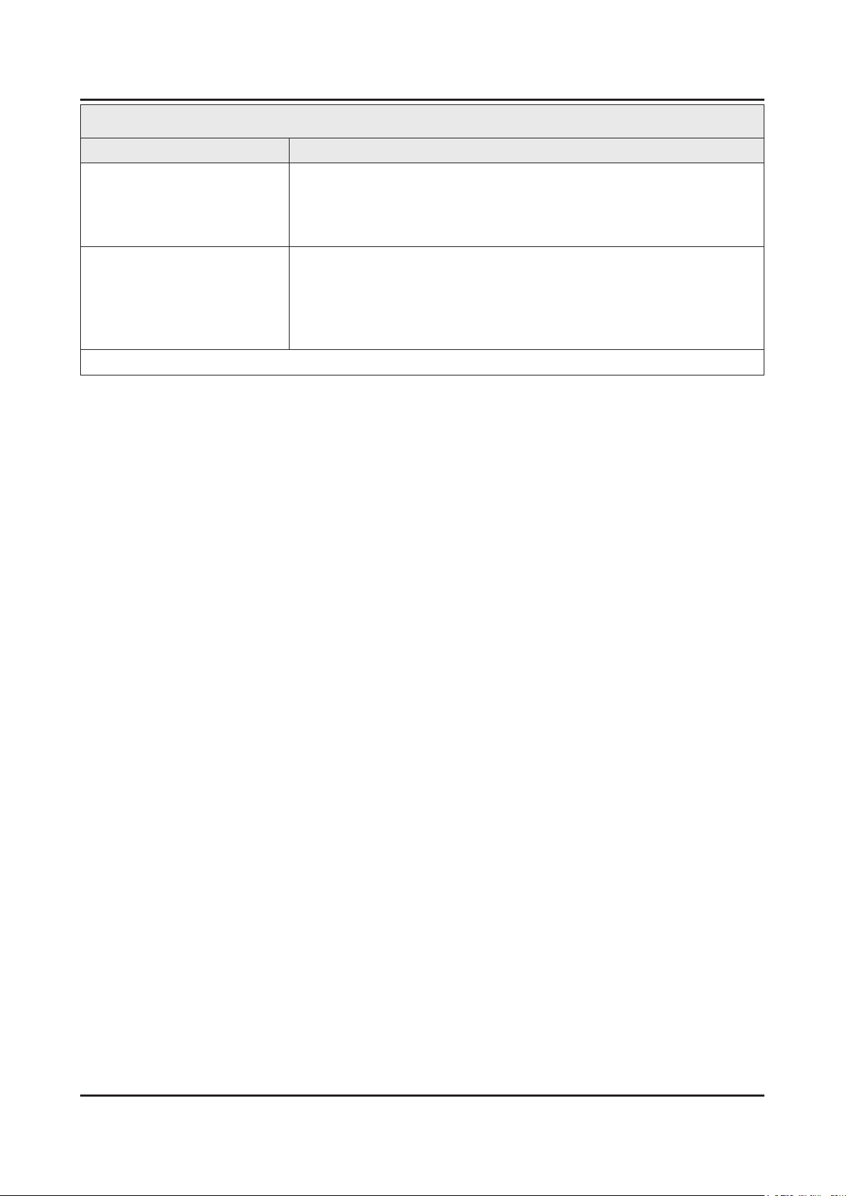
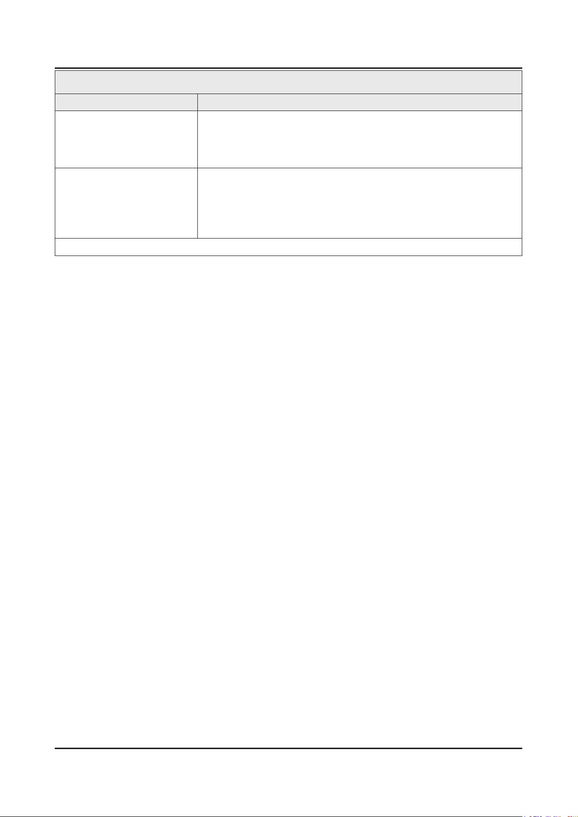
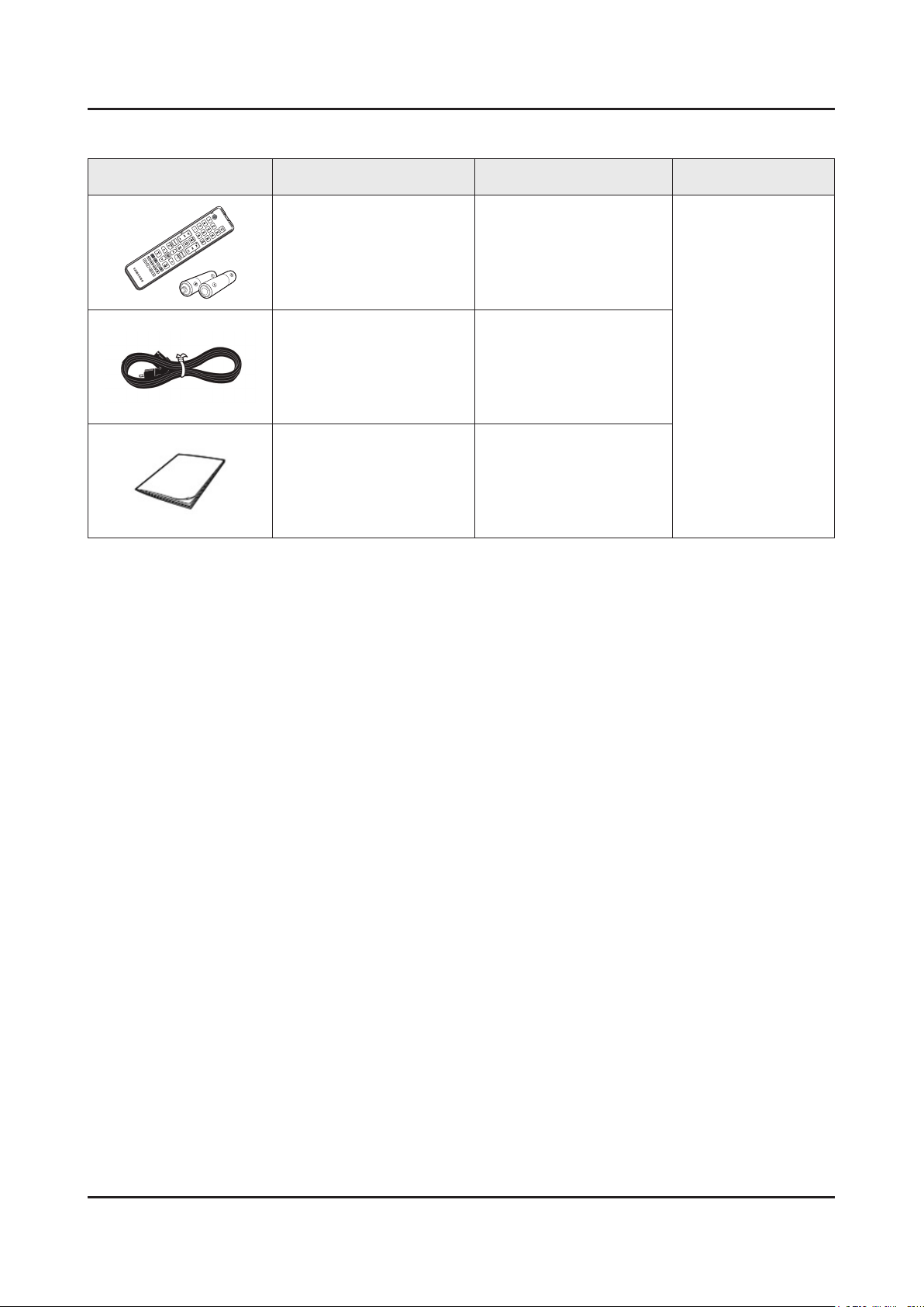
2-2. Accessories
Product Description Code. No Remark
Remote Control & Batteries
(AAA x 2)
Power Cord 3903-000843
Owners Manual BN68-04789A
AA59-00802A
Samsung Electronics
Service center
3. Disassembly and Reassemble
3. Disassembly and Reassembly
This section of the service manual describes the disassembly and reassembly procedures for the LED TV.
This LED TV contains electrostatically sensitive devices. Use caution when handling these components.
WARNING
3-1. Disassembly and Reassembly
Disconnect the LED TV from the power source before disassembly.1.
Follow these directions carefully; never use metal instruments to pry apart the cabinet.2.
CAUTION
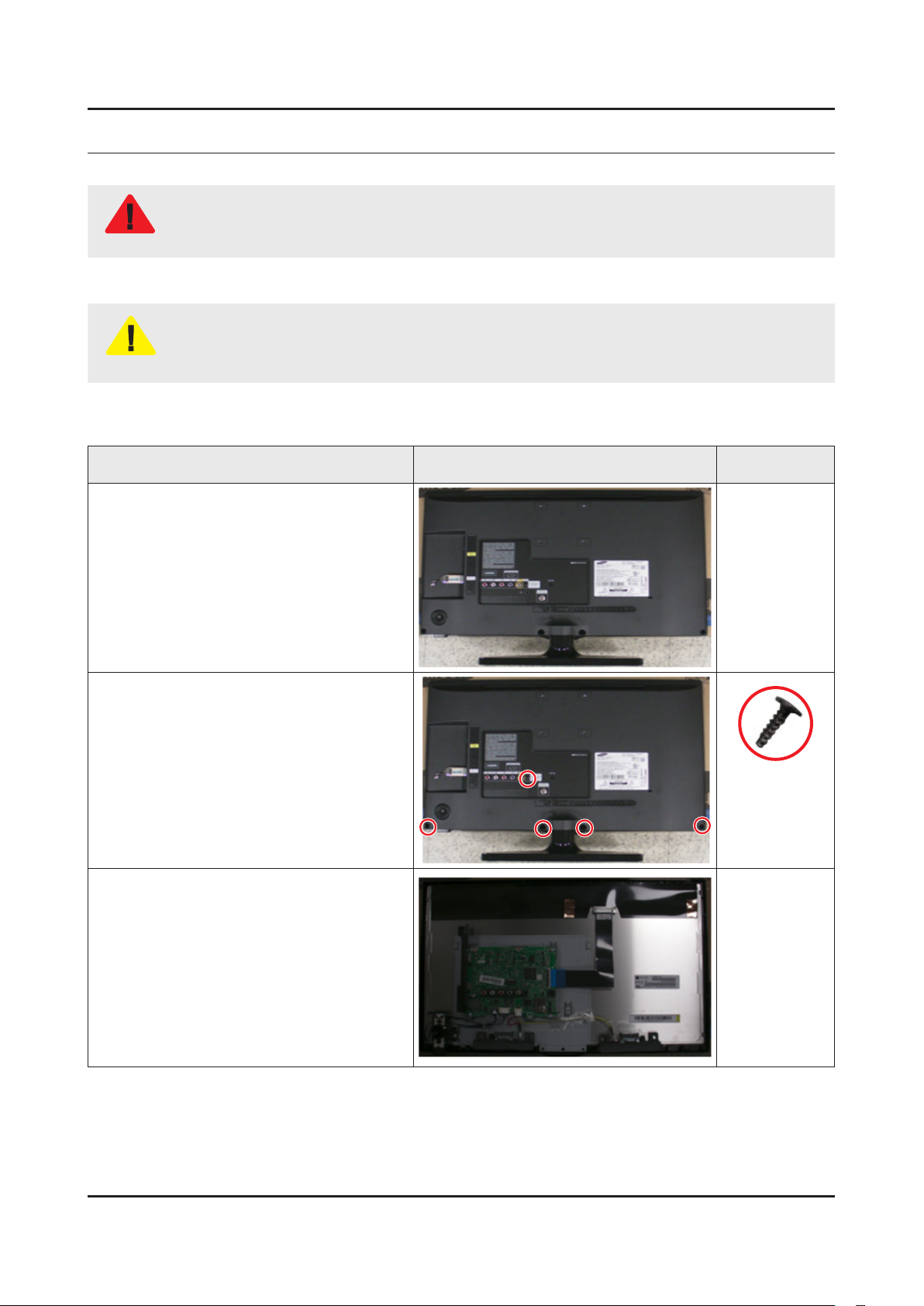
UA22F5000AR
Place TV face down on cushioned table.
If there is no additional coment, it is same for all inches.3.
Description Picture Description Screws
1
Remove 5 screws of Rear Cover.
2
Remove the Rear Cover.
3
6003-001782
3-1
3-2
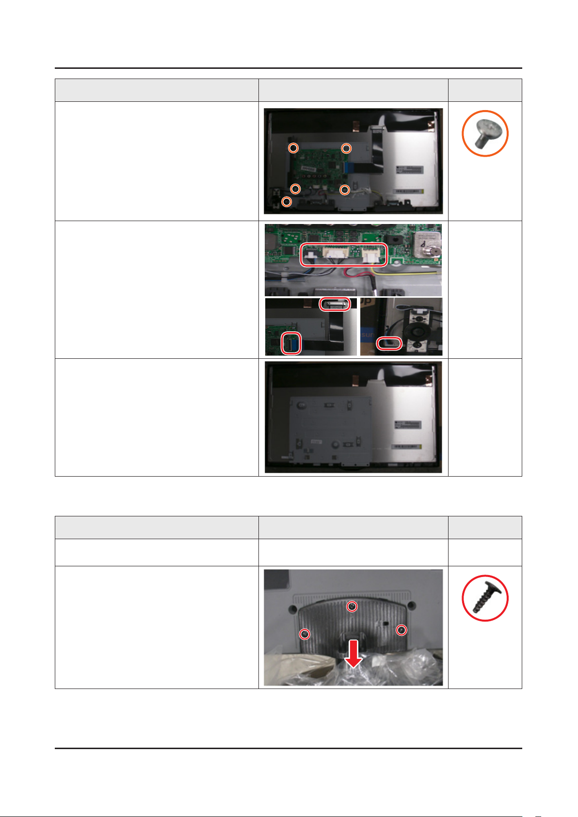
3. Disassembly and Reassemble
Description Picture Description Screws
Remove 5 screws of Main Board and
4
Function Assy.
Remove the Speakers, Function Assy
5
Cable, LVDS Cable and BackLight Cable.
6001-003016
Completed disassembly.
6
UA28F4000AR
Description Picture Description Screws
Place TV face down on cushioned table.
1
Remove 3 screws from the Stand and
2
Remove Stand.
6003-001782
3-3
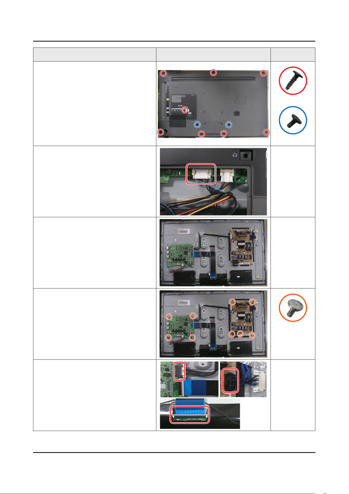
3. Disassembly and Reassemble
Description Picture Description Screws
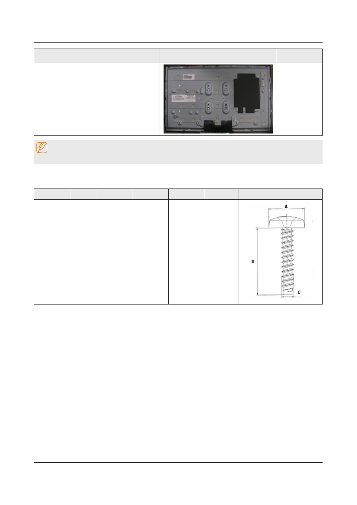
Remove 10 screws of Rear Cover.
3
Remove the Cover Jack and Function
4
Assy Cable
6003-001782
6003-002755
Remove the Rear Cover.
5
Remove 9 screws of Main Board and
6
Power Board.
Remove the Speakers, Power Cables,
7
LVDS Cable and Panel Drive Cable.
6001-003016
3-4
3. Disassembly and Reassemble
Description Picture Description Screws
Completed disassembly.
8
NOTE
Reassembly procedures are in the reverse order of disassembly procedures.
Screw Size
Code No. COLOR A (mm) B (mm) C (mm) Q'ty Screw Image
6003-001782 BLACK 7.80~8.30 11.20~12.00 3.81~3.91
6001-003016
6003-000115 BLACK 5.8~6.3 5.5~6.0 2.95~3.05
WHITE 7.1~7.5
4.7~5.0 2.92 ~ 2.98
19" : 5EA
22" : 5EA
28" : 7EA
19" : 4EA
22" : 5EA
28" : 9EA
19" : 2EA
28" : 2EA
3-5
3. Disassembly and Reassemble
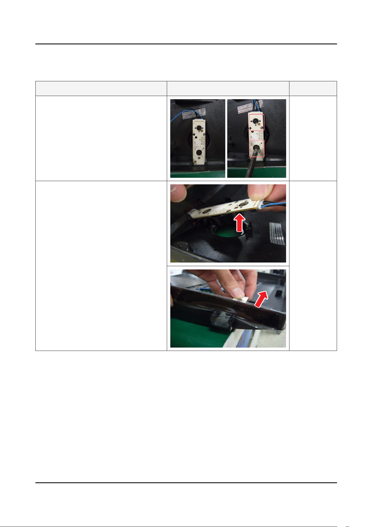
3-2. Assy Board P-Jog Switch & Ir
How to disassembly
Description Picture Description Refer
Loosen 2 screws.
1
Pull out a jog function.
2
3-6
3. Disassembly and Reassemble
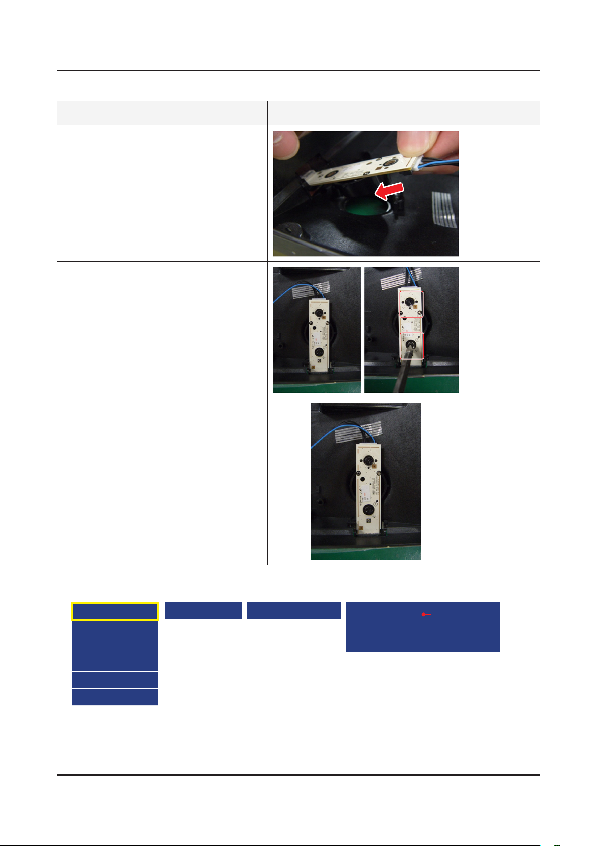
How to assembly
Description Picture Description Refer
Insert a jog function.
1
Put 2 screws.
2
Press the function assy into the cabinet
3
until locked
When you want to ignore the funtion key actions
Option
Control
Debug
SVC
ADC/WB
Advanced
Engineer Option Type of PANEL KEY
5 way : IR + Key
Old : Touch Function (C model) Key
IR Only : Do not work Function key
[ Default ]
3-7
3. Disassembly and Reassemble
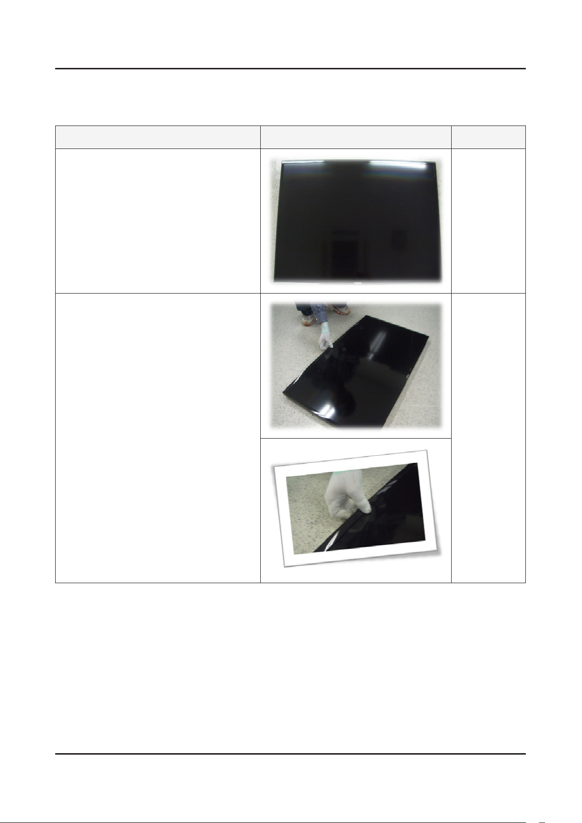
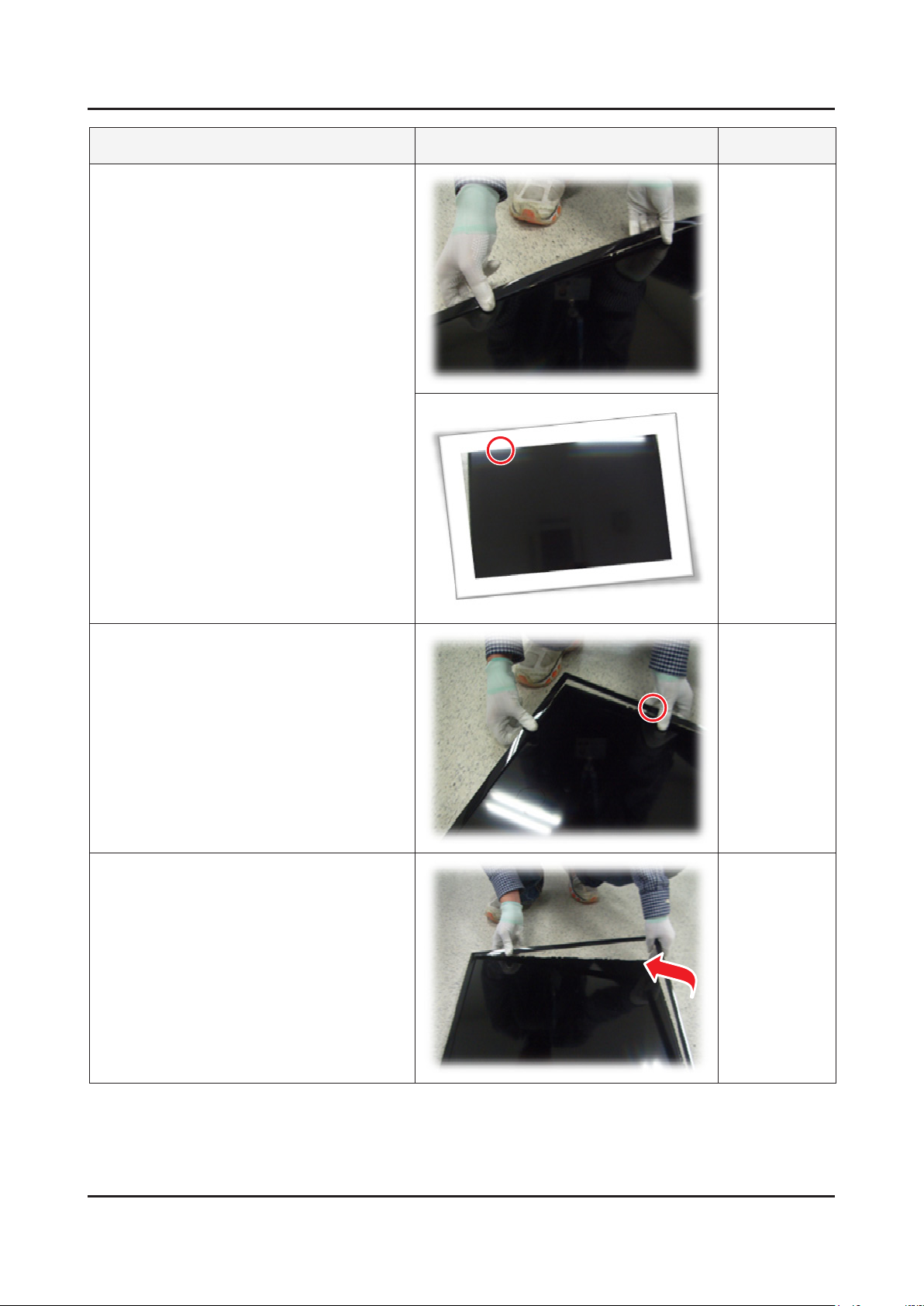
3-3. Disassembly(PTC)
How to disassembly
Description Picture Description Refer
Place TV face up on cushioned table.
1
Products at the top of the central TOP-
2
CHASSIS is rotated by 45 degrees outward
and pulls.
3-8
3. Disassembly and Reassemble
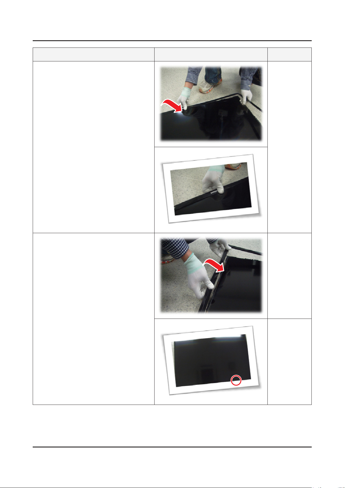
Description Picture Description Refer
Pull in the same way from the center of the
3
top.
Pull the left part of the product as shown
4
while holding the raised portion on gure 3.
Pull the bottom part of the product as
5
gure 2 while holding the raised portion on
gure 4.
3-9
3. Disassembly and Reassemble
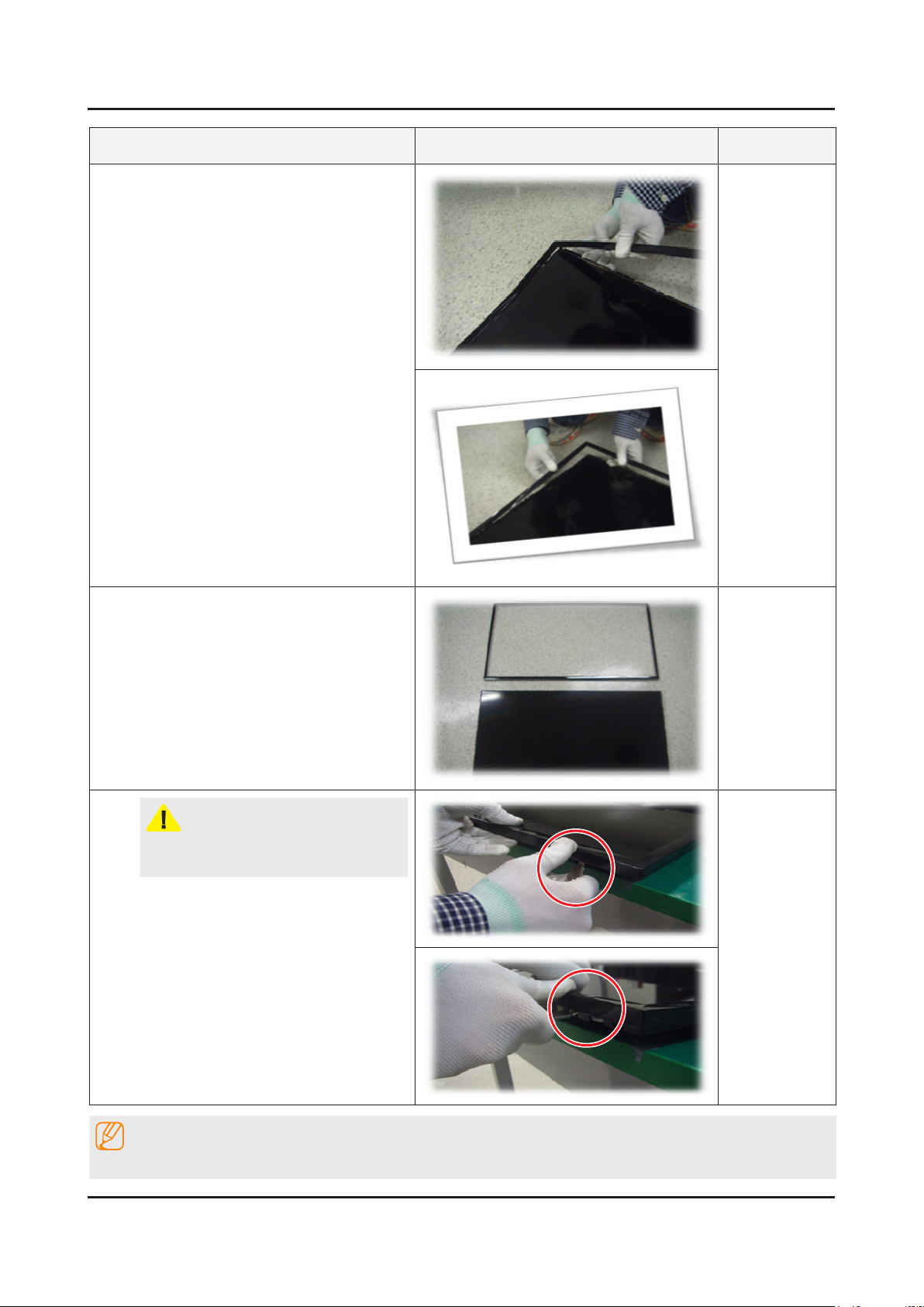
Description Picture Description Refer
As shown in the picture, Lift the bottom of
6
the TOP-CHASSIS.
Pull the products at the bottom of the right
7
side of the chassis.
3. Disassembly and Reassemble
Description Picture Description Refer
Lift the bottom of the chassis with one
8
hand and holding the bottom of the product
after you pull the right side of the product
chassis.
Disassembly is complete.
9
CAUTION
To use JIG : Does not lift the chassis by
hand, JIG using the lift.
NOTE
Reassembly procedures are in the reverse order of disassembly procedures.
3-10
4. Troubleshooting
4-1. Troubleshooting
Previous Check
Check the various cable connections rst.1.
Check to see if there is a burnt or damaged cable. -
Check to see if there is a disconnected or loose cable connection. -
Check to see if the cables are connected according to the connection diagram. -
Check the power input to the Main Board.2.
SMPS Model (UA28F4000A) -
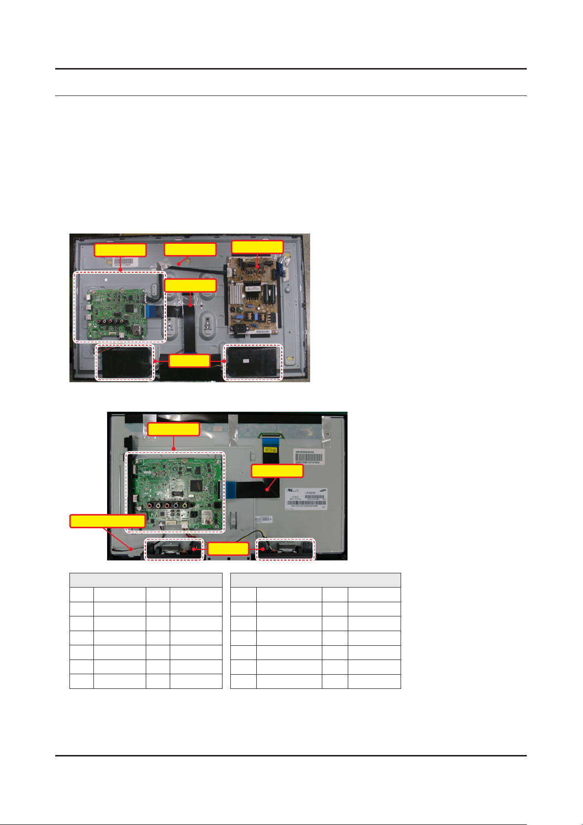
4. Troubleshooting
Main Ass’y
Adaptor Model (UA19F4000A/UA22F5000A) -
BackLight Cable
14P Cable
LVDS Cable
Speaker
Main Ass’y
Power Ass’y
LVDS Cable
Speaker
Main Board Assy (CN201)
13 B13V 14 PWM_DIM
11 B13V 12 B13V
9 B13VS 10 SW_INV
7 B13VS 8 GND
5 GND 6 GND
3 B5.3V 4 A5.3V
1 B5.3V 2 SW_PW
* Change the 14Pin to PWM_DIM(2013 years) from B13V(2012 years)
Check the power in & output between IP & Main Board, Main Board & Panel, IP & Panel.3.
Power Board Assy (CNM803)
14 PS ON/OFF 13 B5V
12 A5V 11 B5V
10 GND 9 GND
8 GND 7 Vamp
6 BLU_ON/OFF 5 Vamp
4 ECO_ON/OFF 3 B13V
2 PWM_DIM 1 B13V
4-1
4-2
4. Troubleshooting
How to know it is from Main Board or T-Con when some problems happen
No Picture : Backlight is on, but there is no picture and LED indicator in front of TV is blinking.1.
Check the LVDS Cable connection. If still problems, change the T-Con Board and then Main Board step by step. -
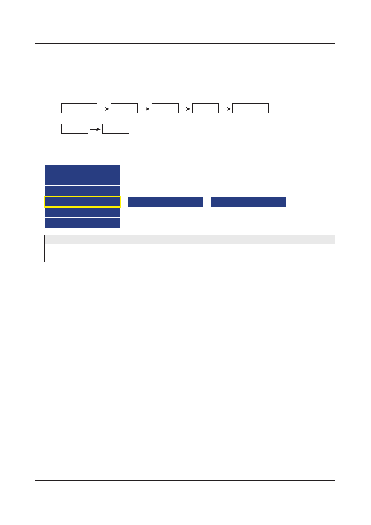
Picture distortion : Enter the service mode 2. ⇢ Choose ‘SVC’ ⇢ Check the ‘internal pattern.’
Enter ‘Service Mode.’ -
If you do not have Factory remote control•
Power OFF Info MENU Mute Power On
If you have Factory remote control•
INFO Factory
Choose ‘SVC.’3.
Choose ‘Test pattern.’4.
Select the each pattern and then check all pattern is ok or not.5.
Option
Control
Debug
SVC
ADC/WB
Advanced
Pattern Status is Change the Test Pattern is made by the MSTAR IC
OK Main Board We guess front of MSTAR IC has problem.
NG Panel and T-Con Board We guess back of MSATR IC has problem.
Test Pattern Mstar Test Pattern
4-3
4. Troubleshooting
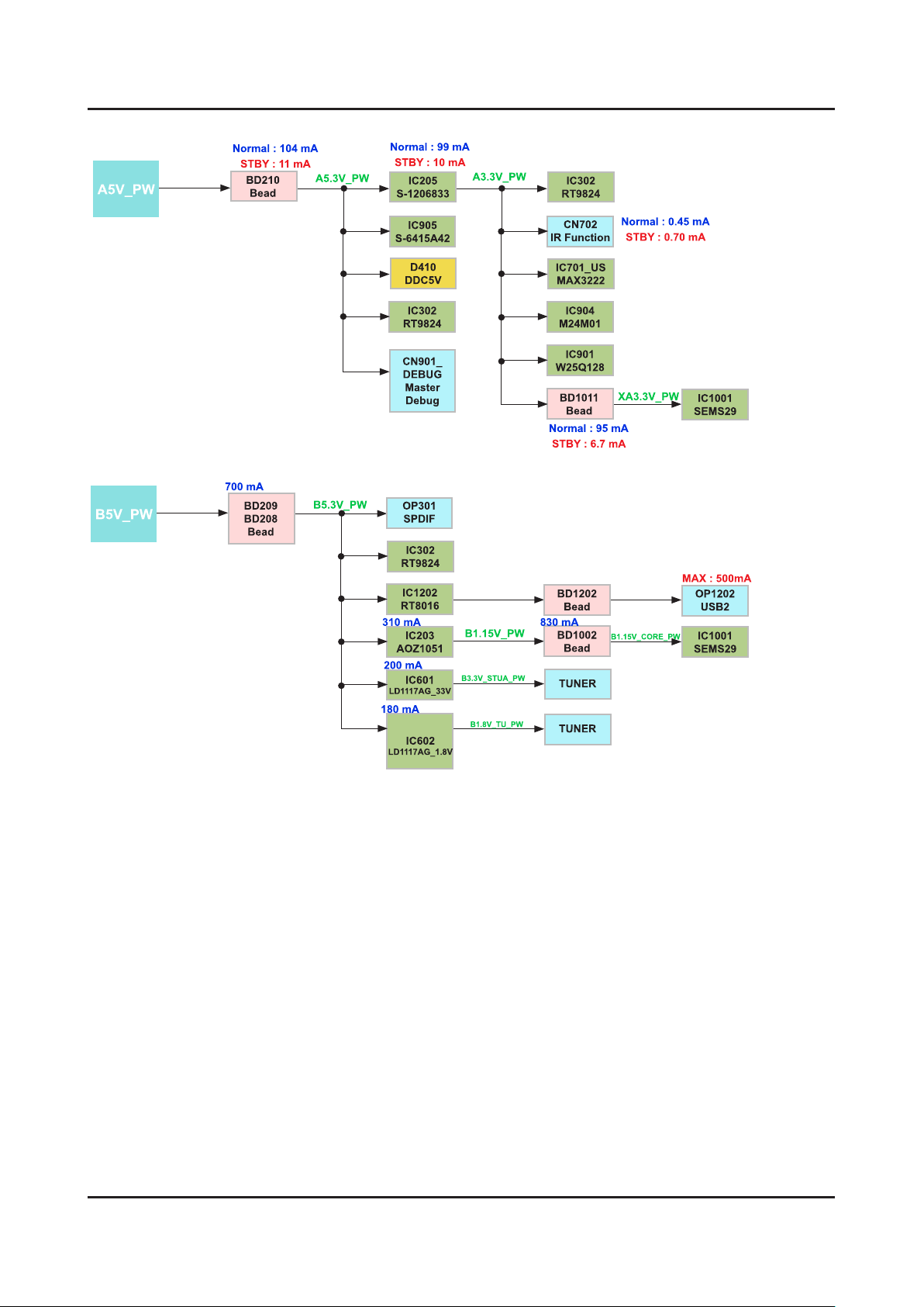
Power-Tree
 Loading...